JP4498174B2 - Image area information generating apparatus, image area information generating method, and program - Google Patents
Image area information generating apparatus, image area information generating method, and program Download PDFInfo
- Publication number
- JP4498174B2 JP4498174B2 JP2005064402A JP2005064402A JP4498174B2 JP 4498174 B2 JP4498174 B2 JP 4498174B2 JP 2005064402 A JP2005064402 A JP 2005064402A JP 2005064402 A JP2005064402 A JP 2005064402A JP 4498174 B2 JP4498174 B2 JP 4498174B2
- Authority
- JP
- Japan
- Prior art keywords
- image
- image data
- destination
- unit
- area information
- Prior art date
- Legal status (The legal status is an assumption and is not a legal conclusion. Google has not performed a legal analysis and makes no representation as to the accuracy of the status listed.)
- Active
Links
Images


Classifications
-
- H—ELECTRICITY
- H04—ELECTRIC COMMUNICATION TECHNIQUE
- H04N—PICTORIAL COMMUNICATION, e.g. TELEVISION
- H04N1/00—Scanning, transmission or reproduction of documents or the like, e.g. facsimile transmission; Details thereof
- H04N1/32—Circuits or arrangements for control or supervision between transmitter and receiver or between image input and image output device, e.g. between a still-image camera and its memory or between a still-image camera and a printer device
- H04N1/333—Mode signalling or mode changing; Handshaking therefor
- H04N1/33307—Mode signalling or mode changing; Handshaking therefor prior to start of transmission, input or output of the picture signal only
-
- A—HUMAN NECESSITIES
- A47—FURNITURE; DOMESTIC ARTICLES OR APPLIANCES; COFFEE MILLS; SPICE MILLS; SUCTION CLEANERS IN GENERAL
- A47L—DOMESTIC WASHING OR CLEANING; SUCTION CLEANERS IN GENERAL
- A47L1/00—Cleaning windows
- A47L1/06—Hand implements
- A47L1/08—Hand implements with provision for supplying liquids, e.g. cleaning agents
-
- A—HUMAN NECESSITIES
- A47—FURNITURE; DOMESTIC ARTICLES OR APPLIANCES; COFFEE MILLS; SPICE MILLS; SUCTION CLEANERS IN GENERAL
- A47L—DOMESTIC WASHING OR CLEANING; SUCTION CLEANERS IN GENERAL
- A47L1/00—Cleaning windows
- A47L1/06—Hand implements
- A47L1/15—Cloths, sponges, pads, or the like, e.g. containing cleaning agents
-
- H—ELECTRICITY
- H04—ELECTRIC COMMUNICATION TECHNIQUE
- H04N—PICTORIAL COMMUNICATION, e.g. TELEVISION
- H04N2201/00—Indexing scheme relating to scanning, transmission or reproduction of documents or the like, and to details thereof
- H04N2201/32—Circuits or arrangements for control or supervision between transmitter and receiver or between image input and image output device, e.g. between a still-image camera and its memory or between a still-image camera and a printer device
- H04N2201/333—Mode signalling or mode changing; Handshaking therefor
- H04N2201/33307—Mode signalling or mode changing; Handshaking therefor of a particular mode
- H04N2201/33342—Mode signalling or mode changing; Handshaking therefor of a particular mode of transmission mode
- H04N2201/33357—Compression mode
Description
本発明は、画像形成装置およびデータ処理方法に関し、より詳細には、画像データ処理を効率的に行う画像形成装置およびデータ処理方法に関する。 The present invention relates to an image forming apparatus and a data processing method, and more particularly to an image forming apparatus and a data processing method for efficiently performing image data processing.
近年メモリやハードディスクの低価格化、CPUの高性能化に伴い、一台の画像入出力装置で複数の機能を同時に実行できる機器が普及してきている。またコンピュータとネットワークの普及に伴い画像入出力装置にネットワークインターフェースを接続して、ネットワークを介して画像データの送受信が行われている。具体的には原稿を光学系読み取り装置により読み取り、アナログ−デジタル変換を施した画像データをハードディスクに蓄積し、ハードディスクに蓄積した画像データを、ユーザーの指定した宛先にFAX送信したり、ユーザーの指定した複写動作や印刷動作をしたりする多機能複写機が提案されている。また多機能複写機はネットワークインターフェースを備える場合があり、この場合には蓄積した画像データをネットワーク経由で指定したコンピュータに送信したり、逆にコンピュータから出力されたプリンタ記述言語に従って画像データを生成して出力したりするなどの機能をもつことが可能である。 In recent years, with the lower prices of memory and hard disks and higher performance of CPUs, devices that can simultaneously execute multiple functions with a single image input / output device have become widespread. Also, with the spread of computers and networks, a network interface is connected to an image input / output device, and image data is transmitted and received via the network. Specifically, the original is read by an optical reader, the analog-digital converted image data is stored on the hard disk, and the image data stored on the hard disk is faxed to a destination specified by the user, or specified by the user. Multifunctional copiers that perform the above-described copying and printing operations have been proposed. Multi-function copiers may be equipped with a network interface. In this case, the stored image data is sent to a specified computer via the network, or image data is generated according to the printer description language output from the computer. It is possible to have functions such as
このような多機能複写機で扱う画像データは、多機能複写機の光学系読取装置で読み込まれる原稿や、コンピュータから送られてくるプリンタ記述言語によるものなど多数あるが、近年はコンピュータの低価格化、パフォーマンスの向上によりカラーデータをユーザーが容易に作成できるようになってきているため、多機能複写機の扱う画像データは白黒の画像データからカラーの画像データに移りつつある。 There are many types of image data handled by such multi-function copiers, such as originals read by the optical system readers of multi-function copiers and printer description languages sent from computers. Since the color data can be easily created by the user due to the increase in performance and performance, the image data handled by the multi-function copying machine is moving from the monochrome image data to the color image data.
一般に、カラーの画像データは、白黒の画像データと比較してデータ量で倍以上のデータ量になる。このため、これを多機能複写機で扱う場合には非常にデータ量が多くなることから、通常は画像データを非可逆圧縮しながらメモリに格納し、ネットワークを介してのコンピュータに対して送信する際や印刷の際に圧縮された画像データを伸張して処理することが行われる。また、カラー画像を印刷するときに最適な画像処理を行うため、画像データの各ページごとの色や文字などの像域情報を判別して、印刷するときの画像処理を調整するようなことも行われている(例えば、特許文献1参照)。 In general, color image data has a data amount more than double that of black and white image data. For this reason, when this is handled by a multi-function copying machine, the amount of data becomes very large. Therefore, image data is usually stored in memory while being irreversibly compressed and transmitted to a computer via a network. The image data compressed at the time of printing or printing is decompressed and processed. In addition, in order to perform optimal image processing when printing a color image, it is possible to determine image area information such as color and characters for each page of image data and adjust the image processing when printing. (For example, refer to Patent Document 1).
これらの処理はユーザーの指定で一度に複数の処理を実行させることも可能である。具体的には多機能複写機の光学系読取装置で読み取った画像データを、ハードディスクに保存するとともにネットワーク上のコンピュータに送信し、ハードディスクに保存されている画像データをユーザーが後に印刷指示をすることにより、ハードディスクにある非可逆圧縮された画像データを伸張して印刷することも可能である。通常、このとき保存されている非可逆圧縮された画像データは1種類であり、非可逆圧縮された画像データを伸張するときに各用途ごとに色空間変換や画像フォーマット変換を行って送信や印刷を行う。これは各用途ごとに画像データを生成して記憶しようとすると、各用途ごとに複数の画像データを生成することになり、一度のユーザー指定で大量の画像用メモリが消費され、他のユーザーの処理を中断する可能性があるためである。 These processes can be executed at a time by a user's specification. Specifically, image data read by an optical reader of a multi-function copier is stored on a hard disk and transmitted to a computer on a network, and the user later instructs the image data stored on the hard disk to print. Thus, it is possible to decompress and print the irreversibly compressed image data in the hard disk. Normally, there is only one type of irreversibly compressed image data stored at this time, and when decompressing the irreversibly compressed image data, color space conversion or image format conversion is performed for each application, and transmission or printing is performed. I do. This means that if image data is generated and stored for each application, multiple image data are generated for each application, and a large amount of image memory is consumed by a single user specification. This is because the processing may be interrupted.
しかしながら、上述のようにカラー画像の非可逆圧縮を使用するとカラー画像データの画像容量は小さくなるが、伸張したときには元の画像データと比較して画質が劣化するという問題が発生する。このような画像データをプリントアウトした場合には、プリント時に画像データに対してスクリーン処理などが施されるため画質の劣化は目立たないが、画像データをネットワーク経由または公衆回線経由でデジタルデータとしてコンピュータやFAXに送信した場合には、スクリーン処理などが施されていないデータを送信するため、受信側の機器で画像を閲覧したときに画質の劣化が目立つことになる。特にカラー画像の非可逆圧縮として一般に用いられるJPEGなどでは、圧縮の工程でブロック単位で処理を行っている関係上、ブロックノイズが発生しやすい。 However, when irreversible compression of a color image is used as described above, the image capacity of the color image data is reduced. However, when decompressed, there is a problem that the image quality is deteriorated as compared with the original image data. When such image data is printed out, image processing is not noticeable because screen processing is performed on the image data at the time of printing, but the image data is converted into digital data via a network or public line as a computer. When the data is transmitted to a fax, data that has not been subjected to screen processing is transmitted, so that when the image is viewed on the receiving device, the image quality is noticeably deteriorated. In particular, in JPEG or the like generally used for irreversible compression of a color image, block noise is likely to occur because the processing is performed in units of blocks in the compression process.
一方、このような画質の劣化を抑えるためには、上述の非可逆圧縮時の圧縮率を低くすることが有効であるがその場合には圧縮後のメモリ容量が大きくなってしまうという問題がある。 On the other hand, in order to suppress such deterioration of image quality, it is effective to reduce the compression rate at the time of irreversible compression, but in that case, there is a problem that the memory capacity after compression becomes large. .
本発明は、上記課題に鑑みてなされたものであり、ユーザーが設定した処理内容に従って、効率的に画像メモリ領域を使用することを可能とする画像形成装置および画像データ処理方法を提供することを目的とする。 The present invention has been made in view of the above problems, and provides an image forming apparatus and an image data processing method that can efficiently use an image memory area in accordance with the processing content set by a user. Objective.
このような目的を達成するために、本発明の像域情報生成装置は、画像データを読み取る読取手段と、画像データから像域情報を生成する像域情報生成手段と、生成した画像データを圧縮する圧縮手段と、圧縮された画像データを記憶する記憶手段と、記憶された画像データを送信する宛先を設定する設定手段と、設定された宛先がプリンタの宛先であるか、コンピュータの宛先であるかを判定する判定手段と、判定手段により宛先が印刷する可能性がない装置の宛先であると判定した場合、宛先プリンタの宛先であると判定した場合の圧縮率よりも低い圧縮率で圧縮手段が画像データを圧縮し、および像域生成手段が、像域情報を生成しないように制御する制御手段とを備えたことを特徴とする。 In order to achieve such an object, an image area information generation apparatus according to the present invention includes a reading unit that reads image data, an image area information generation unit that generates image area information from image data, and compresses the generated image data. Compression means for storing, storage means for storing the compressed image data, setting means for setting a destination for transmitting the stored image data, and the set destination is a printer destination or a computer destination Determining means for determining whether or not the destination is a destination of a device that is unlikely to be printed by the determining means, and the compression means at a compression rate lower than the compression rate when the destination is determined to be the destination of the destination printer Is characterized by compressing the image data, and the image area generating means includes control means for controlling so as not to generate image area information.
また、本願発明の像域情報生成方法は、画像データを読み取る読取ステップと、画像データから像域情報を生成する像域情報生成ステップと、生成した画像データを圧縮する圧縮ステップと、圧縮された画像データを記憶する記憶ステップと、記憶された画像データを送信する宛先を設定する設定ステップと、設定された宛先がプリンタの宛先であるか、コンピュータの宛先であるかを判定する判定ステップと、判定ステップにおいて宛先がコンピュータの宛先であると判定した場合、圧縮ステップにおいて、宛先がプリンタの宛先であると判定した場合の圧縮率よりも低い圧縮率で画像データを圧縮し、および像域情報生成ステップにおいて、像域情報を生成しないように制御する制御ステップとを備えたことを特徴とする。さらに、本願発明のプログラムは、コンピュータに、像域情報生成方法を実行させるプログラムであって、像域情報生成方法は、画像データを読み取る読取ステップと、画像データから像域情報を生成する像域情報生成ステップと、生成した画像データを圧縮する圧縮ステップと、圧縮された画像データを記憶する記憶ステップと、記憶された画像データを送信する宛先を設定する設定ステップと、設定された宛先がプリンタの宛先であるか、コンピュータの宛先であるかを判定する判定ステップと、判定ステップにおいて宛先がコンピュータの宛先であると判定した場合、圧縮ステップにおいて、宛先がプリンタの宛先であると判定した場合の圧縮率よりも低い圧縮率で画像データを圧縮し、および像域情報生成ステップにおいて、像域情報を生成しないように制御する制御ステップとを備えたことを特徴とする。
The image area information generation method of the present invention includes a reading step for reading image data, an image area information generation step for generating image area information from the image data, a compression step for compressing the generated image data, and a compression step. A storage step for storing image data; a setting step for setting a destination for transmitting the stored image data; a determination step for determining whether the set destination is a printer destination or a computer destination; When it is determined that the destination is a computer destination in the determination step, the image data is compressed at a compression rate lower than the compression rate when the destination is determined to be the printer destination in the compression step, and image area information generation is performed. And a control step for controlling so as not to generate image area information. Furthermore, the program of the present invention is a program that causes a computer to execute an image area information generation method, and the image area information generation method includes a reading step for reading image data, and an image area for generating image area information from the image data. An information generation step, a compression step for compressing the generated image data, a storage step for storing the compressed image data, a setting step for setting a destination to which the stored image data is transmitted, and the set destination is a printer A determination step for determining whether the destination is a computer destination, and a determination step in which it is determined in the determination step that the destination is a computer destination, and a determination in the compression step that the destination is a printer destination The image data is compressed at a compression rate lower than the compression rate, and the image area information is generated in the image area information generation step. Characterized by comprising a control step of controlling so as not to generate.
以上説明したように、本発明によれば、読取手段により読み取られた画像データにいずれの処理を行うかの設定を行なう設定手段と、設定された処理に基づいて像域情報を生成するか否かを判定する判定手段と、像域情報を生成しないと判定した場合、像域情報生成手段に像域情報の生成を行なわせず、および圧縮手段に像域情報を生成する場合の圧縮率よりも低い圧縮率により画像データを圧縮させて記憶手段に記憶する制御手段とを備えているので、ユーザーが設定した処理内容に従って、効率的に画像メモリ領域を使用することを可能とする画像形成装置および画像データ処理方法を提供することができる。 As described above, according to the present invention, the setting means for setting which process is performed on the image data read by the reading means, and whether or not the image area information is generated based on the set process. If it is determined that the image area information is not generated by the determination means for determining whether the image area information is not generated by the image area information generation means, and the compression ratio when the image area information is generated by the compression means And an image forming apparatus capable of efficiently using the image memory area in accordance with the processing content set by the user. In addition, an image data processing method can be provided.
以下、図面を参照して本発明の実施形態について説明する。
(第1実施形態)
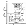
図1は、本発明の一実施形態の装置の全体構成を示すブロック図である。読取手段であるリーダー部(画像入力装置)200は、原稿画像を光学的に読み取って画像データに変換し、原稿を読取るための機能を持つスキャナユニット210と、原稿用紙を搬送するための機能を持つ原稿給紙ユニット250とを備える。
Hereinafter, embodiments of the present invention will be described with reference to the drawings.
(First embodiment)
FIG. 1 is a block diagram showing the overall configuration of an apparatus according to an embodiment of the present invention. A reader unit (image input device) 200 serving as a reading unit optically reads a document image and converts it into image data, and has a function of conveying a document sheet and a
画像形成手段であるプリンタ部(画像出力装置)300は、記録紙を搬送しつつ、その上に画像データを可視画像として形成し装置外に排紙する。プリンタ部300はまた、複数種類の記録紙カセットを持つ給紙ユニット310と、画像データを記録紙に転写および定着させる機能を持つマーキングユニット320と、印字された記録紙をソートしまたはステイプルを行なって機外へ出力する機能を持つ排紙ユニット330とを備える。
A printer unit (image output device) 300 serving as an image forming unit conveys a recording sheet, forms image data on the recording sheet as a visible image, and discharges the image data outside the apparatus. The
制御装置110は、リーダー部200、プリンタ部300と電気的に接続され、さらにネットワーク400を介して、ホストコンピュータ411、412と接続される。制御装置110は、リーダー部200を制御して原稿の画像データを読込み、プリンタ部300を制御して画像データを記録用紙に出力することによってコピー機能を提供する。また、リーダー部200から読取った画像データをコードデータに変換し、ネットワーク400を介してホストコンピュータへ送信するスキャナ機能、ホストコンピュータからネットワーク400を介し受信したコードデータを画像データに変換してプリンタ部300に出力するプリンタ機能を提供する。
The
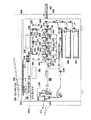
指定受付け手段である操作部150は、液晶タッチパネルを備え、画像入出力システムを操作するためのユーザーI/Fを提供し、制御装置110に接続される。図2は、本実施形態のリーダー部200及びプリンタ部300の概観図である。リーダー部の原稿給送ユニット250は原稿を先頭順に1枚ずつプラテンガラス211上へ給送して原稿の読み取り動作終了後、プラテンガラス211上の原稿を排出するものである。原稿がプラテンガラス211上に搬送されると、ランプ212を点灯して光学ユニット213の移動が開始されて原稿が露光走査される。この時の原稿からの反射光は、ミラー214、215、216及びレンズ217によってCCDイメージセンサ(以下CCDという)218へ導かれる。このように、走査された原稿の画像はCCD218によって読み取られる。
The
リーダー画像処理回路部222は、CCD218から出力される画像データに所定の処理を施し、スキャナI/F140を介して制御装置110へと出力する。プリンタ画像処理回路部352は、プリンタI/F145を介して制御装置110から送られる画像信号をレーザドライバへと出力する。プリンタ部300のレーザドライバ317は、レーザ発光部313、314、315、316を駆動し、プリンタ画像処理部352から出力された画像データに応じたレーザ光をレーザ発光部313、314、315、316を用いて発光させる。このレーザ光がミラー340、341、342、343、344、345、346、347、348、349、350、351によって感光ドラム325、326、327、328に照射されると、感光ドラム325、326、327、328にはレーザ光に応じた潜像が形成される。現像器321、322、323、324は、それぞれ潜像をブラック(Bk)、イエロー(Y)、シアン(C)、マゼンダ(M)のトナーによって、現像し、現像された各色のトナーを用紙に転写してフルカラーのプリントアウトがなされる。
The reader image
用紙カセット360、361及び手差しトレイ362のいずれかより、レーザ光の照射開始と同期したタイミングで給紙された用紙は、レジストローラ333を経て、転写ベルト334上に吸着され、搬送される。そして、感光ドラム325、326、327、328に付着された現像剤を記録紙に転写する。現像剤が転写された記録紙は定着部335に搬送され、定着部335の熱と圧力により現像剤は記像紙に定着される。定着部335を通過した記録紙は排出ローラ336によって排出され、排紙ユニット370は排出された記録紙を束ねて記録紙の仕分けをしたり、仕分けされた記録紙にステイプル処理を行ったりする。
A sheet fed from one of the
また、両面記録が設定されている場合、排出ローラ336のところまで記録紙を搬送した後、排出ローラ336の回転方向を逆転させ、フラッパ337によって再給紙搬送路338へ導く。再給紙搬送路338へ導かれた記録紙は上述したタイミングで転写ベルト334へ給紙される。
When double-sided recording is set, after the recording paper is conveyed to the
<リーダー画像処理部の説明>
図3は、本発明の一実施形態のリーダー画像処理部222の詳細な構成を示すブロック図である。このリーダー画像処理部222は、プラテンガラス211上の原稿からCCD218により読み取られた信号の処理を行って所定の電気信号に変換する(CCD218はカラーセンサの場合、RGBのカラーフィルタが1ラインCCD上にRGB順にインラインに乗ったものでも、3ラインCCDで、それぞれRフィルタ・Gフィルタ・BフィルタをそれぞれのCCDごとに並べたものでも構わないし、フィルタがオンチップ化、またはフィルタがCCDと別構成になったものでも構わない)。この電気信号(アナログ画像信号)は画像処理部222に入力され、クランプ&Amp.&S/H&A/D部401でサンプルホールド(S/H)され、アナログ画像信号のダークレベルを基準電位にクランプし、所定量に増幅され(上記処理順番は表記順とは限らない)、A/D変換されて、例えばRGB各8ビットのデジタル信号に変換される。そして、RGB信号はシェーディング部402で、シェーディング補正及び黒補正が施された後、制御装置110へと出力される。
<Explanation of Reader Image Processing Unit>
FIG. 3 is a block diagram illustrating a detailed configuration of the reader
<制御装置の説明>
制御装置110の機能を、図4に示すブロック図をもとに説明する。メインコントローラ111は、主にCPU112と、バスコントローラ113、各種I/Fコントローラ回路とから構成される。CPU112とバスコントローラ113は制御装置110全体の動作を制御するものであり、CPU112はROM114からROM I/F115を経由して読込んだプログラムに基づいて動作する。また、ホストコンピュータから受信したPDL(ページ記述言語)コードデータを解釈し、ラスターイメージデータに展開する動作も、このプログラムに記述されており、ソフトウェアによって処理される。バスコントローラ113は各I/Fから入出力されるデータ転送を制御するものであり、バス競合時の調停やDMAデータ転送の制御を行う。
<Description of control device>
The function of the
DRAM116はDRAM I/F117によってメインコントローラ111と接続されており、CPU112が動作するためのワークエリアや、画像データを蓄積するためのエリアとして使用される。Codec118は、DRAM116に蓄積されたラスターイメージデータをMH/MR/MMR/JBIG/JPEG等の方式で圧縮し、また逆に圧縮され蓄積されたコードデータをラスターイメージデータに伸長する。SRAM119はCodec118の一時的なワーク領域として使用される。Codec118はI/F120を介してメインコントローラ111と接続され、DRAM116との間のデータの転送は、バスコントローラ113によって制御されDMA転送される。
The
Graphic Processor135は、DRAM116に蓄積されたラスターイメージデータに対して、画像回転、画像変倍、色空間変換、二値化の処理を行う。SRAM136はGraphic Processor135の一時的なワーク領域として使用される。Graphic Processor135は、I/F137を介してメインコントローラ111と接続され、DRAM116との間のデータの転送は、バスコントローラ113によって制御されDMA転送される。
The
Network Contorller121は、I/F122によってメインコントローラ111と接続され、コネクタ122によって外部ネットワークと接続される。ネットワークとしては一般的にイーサネット(登録商標)があげられる。汎用高速バス125には、拡張ボードを接続するための拡張コネクタ124とI/O制御部126とが接続される。汎用高速バスとしては、一般にPCIバスがあげられる。
The
I/O制御部126には、リーダー部200、プリンタ部300の各CPUと制御コマンドを送受信するための調歩同期シリアル通信コントローラ127が2チャンネル装備されており、I/Oバス128によって外部I/F回路140,145に接続されている。
The I /
パネルI/F132は、LCDコントローラ131に接続され、操作部150上の液晶画面に表示を行うためのI/Fと、ハードキーやタッチパネルキーの入力を行うためのキー入力I/F130とを備える。操作部150は、液晶表示部と液晶表示部上に張り付けられたタッチパネル入力装置、および複数個のハードキーを有する。タッチパネルまたはハードキーにより入力された信号は上述したパネルI/F132を介してCPU112に伝えられ、液晶表示部はパネルI/F520から送られてきた画像データを表示するものである。液晶表示部には、本画像形成装置の操作における機能表示や画像データ等を表示する。
The panel I /
リアルタイムクロックモジュール133は、機器内で管理する日付と時刻を更新/保存するためのもので、バックアップ電池134によってバックアップされている。E-IDEインタフェース161は、外部記憶装置を接続するためのものである。本実施形態においては、このI/Fを介してハードディスクドライブ160を接続し、ハードディスク162へ画像データを記憶させたり、ハードディスク162から画像データを読み込む動作を行う。
The real-
コネクタ142および147は、それぞれリーダー部200およびプリンタ部300に接続され、調歩同期シリアルI/F143、148とビデオI/F144、149とから構成される。スキャナI/F140は、コネクタ142を介してリーダー部200と接続され、またスキャナバス141によってメインコントローラ111と接続されており、リーダー部200から受け取った画像に対して所定の処理を施す機能を有し、さらに、リーダー部200から送られたビデオ制御信号をもとに生成した制御信号を、スキャナバス141に出力する機能も有する。スキャナバス141からDRAM116へのデータ転送は、バスコントローラ113によって制御される。
The
プリンタI/F145は、コネクタ147を介してプリンタ部300と接続され、またプリンタバス146によってメインコントローラ111と接続されており、メインコントローラ111から出力された画像データに所定の処理を施して、プリンタ部300へ出力する機能を有し、さらに、プリンタ部300から送られたビデオ制御信号をもとに生成した制御信号を、プリンタバス146に出力する機能も有する。
DRAM116上に展開されたラスターイメージデータのプリンタ部への転送は、バスコントローラ113によって制御され、プリンタバス146、ビデオI/F149を経由して、プリンタ部300へDMA転送される。
The printer I /
Transfer of raster image data developed on the
<スキャナI/Fの画像処理部の説明>
スキャナI/F140の画像処理を担う部分についての詳細な説明を行う。図5は、本発明の一実施形態のスキャナI/F140の画像処理を担う部分の詳細な構成を示すブロック図である。リーダー部200からコネクタ142を介して送られる画像信号に対し、つなぎ&MTF補正部601において、CCD218が3ラインCCDの場合、つなぎ処理はライン間の読取位置が異なるため、読取速度に応じてライン毎の遅延量を調整し、3ラインの読取位置が同じになるように信号タイミングを補正し、MTF補正は読取速度によって読取のMTFが変るため、その変化を補正する。読取位置タイミングが補正されたデジタル信号は入力マスキング部602によって、CCD218の分光特性及びランプ212及びミラー214、215、216の分光特性を補正する。入力マスキング部602の出力はACSカウント部603及びメインコントローラ111へと送られる。
<Description of scanner I / F image processing unit>
A detailed description will be given of a portion responsible for image processing of the scanner I /
<ACSカウント部の説明>
ACS(オートカラーセレクト)カウント部の説明を図6を参照して行う。オートカラーセレクト(以下ACS)は、原稿がカラーなのか白黒なのかを判断する。つまり画素ごとの彩度を求めてある閾値以上の画素がどれだけ存在するかにより、カラー判定を行うものである。しかし、白黒原稿であっても、MTF等の影響により、ミクロ的に見るとエッジ周辺に色画素が多数存在し、単純に画素単位でACS判定を行うのは難しい。
<Description of ACS count part>
The ACS (auto color select) counting unit will be described with reference to FIG. Auto color select (hereinafter, ACS) determines whether a document is color or monochrome. That is, color determination is performed based on the number of pixels that are equal to or greater than a threshold value for which the saturation of each pixel is obtained. However, even for a black and white original, due to the influence of MTF and the like, when viewed microscopically, there are a large number of color pixels around the edge, and it is difficult to simply perform ACS determination on a pixel basis.
このACS手法はさまざまな方法が提供されているが、本実施形態ではACSの方法の詳細にはふれず、ごく一般的な手法を用いて説明を行う。上述したように、白黒画像でもミクロ的に見ると色画素が多数存在するわけであるから、その画素が本当に色画素であるかどうかは、注目画素に対して周辺の色画素の情報で判定する必要がある。そのためのフィルタ501は、注目画素に対して周辺画素を参照するためにFIFOの構造をとる。回路502は、メインコントローラ111からセットされたレジスタ507〜510に設定された値と、リーダー部200から送られたビデオ制御信号512とに基づいてACSをかける領域信号505を作成する回路である。
Various methods are provided for this ACS method. In this embodiment, details of the ACS method will not be described, and a description will be given using a very general method. As described above, even in a black and white image, there are many color pixels when viewed microscopically. Therefore, whether or not the pixel is really a color pixel is determined based on information on surrounding color pixels with respect to the target pixel. There is a need. Therefore, the
色判定部503は、ACSをかける領域信号505に基づき、注目画素に対して501のフィルタ内のメモリ内の周辺画素を参照し、注目画素が色画素か白黒画素かを決定するためのものである。カウンタ504は、色判定部503が出力した色判定信号の個数を数えるためのものである。メインコントローラ111は、読み込み範囲に対してACSをかける領域を決定し、レジスタ507〜510に設定する(本実施形態では、原稿に対して独立で範囲を決める構成をとる)。また、メインコントローラ111は、ACSをかける領域内での色判定信号の個数を計数するカウンタの値を、所定の閾値と比較し、当該原稿がカラーなのか白黒なのかを判断する。
The
レジスタ507〜510には、主走査方向、副走査方向それぞれについて、色判定部503が判定を開始する位置、判定を終了する位置を、リーダー部200から送られたビデオ制御信号512に基づいて設定しておく。本実施形態では、実際の原稿の大きさよりもそれぞれ10mm程度小さめに設定している。
In the
<プリンタI/Fの画像処理部の説明>
プリンタI/F145の画像処理を担う部分についての詳細な説明を行う。図7は、 本発明の一実施形態のプリンタI/F145の画像処理を担う部分の詳細な構成を示すブロック図である。メインコントローラ111から、プリンタバス146を介して送られる画像信号は、まずLOG変換部701に入力される。LOG変換部701では、LOG変換でRGB信号からCMY信号に変換する。次にモアレ除去部702でモアレが除去される。UCR&マスキング部703は、モアレ除去処理されたCMY信号をUCR処理してCMYK信号を生成し、マスキング処理部でプリンタの出力にあった信号に補正される。UCR&マスキング部703で処理された信号はγ補正部704で濃度調整された後フィルタ部705でスムージング又はエッジ処理される。これらの処理を経て、コネクタ147を介しプリンタ部300へと画像が送られる。
<Description of printer I / F image processing unit>
A detailed description will be given of the portion of the printer I /
<Graphic Processorの説明>
Graphic Processor135についての詳細な説明を行う。図8は、本発明の一実施形態のGraphic Processor135の詳細な構成を示すブロック図である。Graphic Processor135は、画像回転部801、画像変倍部802、色空間変換部803、二値化処理部805といったモジュールを有する。SRAM136はGraphic Processor135の各々のモジュールの一時的なワーク領域として使用される。各々のモジュールが用いるSRAM136のワーク領域が競合しないよう、あらかじめ各々のモジュールごとにワーク領域が静的に割り当てられているものとする。Graphic Processor135は、I/F137を介してメインコントローラ111と接続され、DRAM116との間のデータの転送は、バスコントローラ113によって制御されてDMA転送される。
<Description of Graphic Processor>
The
バスコントローラ113は、GraphicProcessor135の各々のモジュールにモード等を設定する制御及び、各々のモジュールに画像データを転送するためのタイミング制御を行う。
The
<画像回転部の説明>
以下に画像回転部801における処理手順を示す。I/F137を介して、CPU112からバスコントローラ113に画像回転制御のための設定を行う。この設定によりバスコントローラ113は、画像回転部801に対して画像回転に必要な設定(たとえば画像サイズや回転方向・角度等)を行う。必要な設定を行った後に、再度CPU112からバスコントローラ113に対して画像データ転送の許可を行う。この許可に従い、バスコントローラ113はDRAM116もしくは各I/Fを介して接続されているデバイスから画像データの転送を開始する。なお、ここでは回転を行う画像サイズを32画素×32ラインとし、また画像バス146上に画像データを転送させる際に24byte(RGB各々8bitで1画素分)を単位とする画像転送を行うものとする。
<Description of image rotation unit>
The processing procedure in the
上述のように、32画素×32ラインの画像を得るためには、上述の単位データ転送を32×32回行う必要があり、かつ不連続なアドレスから画像データを転送する必要がある(図9参照)。不連続アドレッシングにより転送された画像データは、読み出し時に所望の角度に回転されているように、SRAM136に書き込まれる。例えば、90度反時計方向回転であれば、転送される画像データを、図10のようにY方向に書き込んでいく。読み出し時にX方向に読み出すことで、画像が回転される。32画素×32ラインの画像回転(SRAM136への書き込み)が完了した後、画像回転部801はSRAM136から上述した読み出し方法で画像データを読み出し、バスコントローラ113に画像を転送する。
As described above, in order to obtain an image of 32 pixels × 32 lines, it is necessary to transfer the unit data described above 32 × 32 times, and it is necessary to transfer image data from discontinuous addresses (FIG. 9). reference). The image data transferred by the discontinuous addressing is written in the
回転処理された画像データを受け取ったバスコントローラ113は、連続アドレッシングを以て、DRAM116もしくはI/F上の各デバイスにデータを転送する。こうした一連の処理は、CPU112からの処理要求が無くなるまで(必要なページ数の処理が終わったとき)繰り返される。
The
<画像変倍部の説明>
以下に画像変倍部802における処理手順を示す。
I/F137を介して、CPU112からバスコントローラ113に画像変倍制御のための設定を行う。この設定によりバスコントローラ113は、画像変倍部802に対して画像変倍に必要な設定(主走査方向の変倍率、副走査方向の変倍率、変倍後の画像サイズ等)を行う。必要な設定を行った後に、再度CPU112からバスコントローラ113に対して画像データ転送の許可を行う。この許可に従い、バスコントローラ113は、DRAM116もしくは各I/Fを介して接続されているデバイスから画像データの転送を開始する。画像変倍部802は、受け取った画像データを一時SRAM136に格納し、これを入力バッファとして用いて、格納したデータに対して主走査、副走査の変倍率に応じて必要な画素数、ライン数の分の補間処理を行って画像を拡大もしくは縮小することにより、変倍処理とする。変倍後のデータは、再度SRAM136へ書き戻し、これを出力バッファとして画像変倍部802はSRAM136から画像データを読み出し、バスコントローラ113に転送する。変倍処理された画像データを受け取ったバスコントローラ113は、DRAM116もしくはI/F上の各デバイスにデータを転送する。
<Explanation of image scaling unit>
The processing procedure in the
Setting for image scaling control is performed from the
<色空間変換部の説明>
以下に色空間変換部803における処理手順を示す。I/F137を介して、CPU112からバスコントローラ113に色空間変換制御のための設定を行う。この設定によりバスコントローラ113は色空間変換部803およびLUT(ルック・アップ・テーブル)804に対して色空間変換処理に必要な設定(後述のマトリックス演算の係数、LUT804のテーブル値等)を行う。必要な設定を行った後に、再度CPU112からバスコントローラ113に対して画像データ転送の許可を行う。この許可に従い、バスコントローラ113はDRAM116もしくは各I/Fを介して接続されているデバイスから画像データの転送を開始する。
<Description of color space converter>
The processing procedure in the color
色空間変換部803は、受け取った画像データの1画素ごとに対して、まず下記の式で表される3×3のマトリックス演算を施す。
The color

上式において、R、G、Bが入力、X、Y、Zが出力、a11、a12、a13、a21、a22、a23、a31、a32、a33、b1、b2、b3、c1、c2、c3がそれぞれ係数である。上式の演算によって、例えばRGB色空間からYuv色空間への変換など、各種の色空間変換を行うことができる。 In the above formula, R, G, B are input, X, Y, Z are output, a11, a12, a13, a21, a22, a23, a31, a32, a33, b1, b2, b3, c1, c2, c3 are Each is a coefficient. Various color space conversions such as conversion from the RGB color space to the Yuv color space can be performed by the calculation of the above equation.
次に、マトリックス演算後のデータに対しLUT804による変換を行うことによって、非線形の変換をも行うことができるが、当然、(入力値をそのまま出力する)スルーのテーブルを設定することにより、実質的にLUT変換を行わないようにすることもできる。その後、色空間変換部803は、色空間変換処理された画像データをバスコントローラ113に転送する。色空間変換処理された画像データを受け取ったバスコントローラ113は、DRAM116もしくはI/F上の各デバイスにデータを転送する。
Next, non-linear conversion can also be performed by performing conversion by the LUT804 on the data after the matrix operation, but of course, by setting a through table (outputting the input value as it is) It is also possible not to perform LUT conversion. Thereafter, the color
<画像二値化部の説明>
以下に画像二値化部805における処理手順を示す。I/F137を介して、CPU112からバスコントローラ113に二値化制御のための設定を行う。この設定によりバスコントローラ113は、画像二値化部805に対して二値化処理に必要な設定(変換方法に応じた各種パラメータ等)を行う。必要な設定を行った後に、再度CPU112からバスコントローラ113に対して画像データ転送の許可を行う。この許可に従い、バスコントローラ113はDRAM116もしくは各I/Fを介して接続されているデバイスから画像データの転送を開始する。
<Description of image binarization unit>
The processing procedure in the
画像二値化部805は、受け取った画像データに対して二値化処理を施す。本実施形態における二値化の手法は、画像データを所定の閾値と比較して単純に二値化するものを用いる。もちろん、ディザ法、誤差拡散法、誤差拡散法を改良したものなど、いずれの手法によってもかまわない。その後、画像二値化部805は二値化処理された画像データをバスコントローラ113に転送する。
The
二値化処理された画像データを受け取ったバスコントローラ113は、DRAM116もしくはI/F上の各デバイスにデータを転送する。
The
<PDL画像出力時のシーケンス>
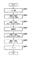
図11は、本実施形態におけるPDL画像出力の手順を示すフローチャートである。なお、図中のS3001〜S3008は各処理のステップを示す。PDL画像を出力する場合、ステップS3001において、PC411上でユーザーが当該PDL画像出力ジョブのプリント設定を行う。プリント設定内容は、部数、用紙サイズ、片面/両面、ページ出力順序、ソート出力、ステイプル止めの有無等である。
<PDL image output sequence>
FIG. 11 is a flowchart showing a PDL image output procedure in the present embodiment. Note that S3001 to S3008 in the figure indicate steps of each process. When outputting a PDL image, in step S3001, the user performs print settings for the PDL image output job on the
ステップS3002において、PC411上で印刷指示を与え、それと共にPC411上にインストールされているドライバソフトウェアが印刷対象となるPC411上のコードデータをPDLデータに変換して、ステップS3001で設定したプリント設定パラメータとともに、本画像入出力装置の制御装置110に、ネットワーク400を介してPDLデータを転送する。
In step S3002, a print instruction is given on the
ステップS3003において、制御装置110のメインコントローラ111のCPU112は、コネクタ122およびNetworkController121を介して転送されたPDLデータを前記プリント設定パラメータに基づいて、画像データに展開(ラスタライズ)する。画像データの展開は、DRAM116上で行われる。画像データの展開が完了するとステップS3004へ進む。
In step S3003, the
ステップS3004において、メインコントローラ111がDRAM116上に展開された画像データを、Graphic Processor135に転送する。ステップS3005において、Graphic Processor135が、前記プリント設定パラメータとは独立に画像処理を行う。例えば、前記プリント設定パラメータで指定された用紙サイズがA4であるにもかかわらず、プリンタ部300の給紙ユニット360にはA4R用紙しかない場合、Graphic Processor135で画像を90度回転することによって、出力用紙にあわせた画像出力を行うことができる。画像データの画像処理が完了するとステップS3006へ進む。
In step S3004, the
ステップS3006において、Graphic Processor135はメインコントローラ111へ画像処理後の画像データを転送する。メインコントローラ111は転送されてきた画像データをDRAM116上に記憶する。ステップS3007において、メインコントローラ111は、プリンタI/F145およびコネクタ147を介して、プリンタ部300を制御しつつ、適切なタイミングでDRAM116上の画像データを、プリンタ部300へと転送する。
In step S3006, the
ステップS3008において、制御装置110は、プリンタ部300を制御して画像データをプリント出力する。画像データの転送が完了すると、すなわち当該PDLジョブが終了すると、プリント出力を終了する。
In step S3008,
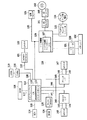
図13は、図3のリーダー画像処理部222で読み込まれRGB信号に変換された画像データを像域判定(文字判定)、カラー判定を行うスキャナI/Fの回路構成を示す図である。リーダー部1302で読み込まれたデジタル画像データは画像データ信号線1303を介してスキャナI/F1301に送られる。
FIG. 13 is a diagram showing a circuit configuration of a scanner I / F that performs image area determination (character determination) and color determination on image data read by the reader
画像データ信号1303を送られてきたデジタル画像データは、リーダー部1302からの制御信号線1306により同期を取りながら、画像データ信号線1303で像域分離(文字判定)部1309に入力される。ここで、像域分離(文字判定)部1309は画像データ信号線1303を介して入力された画像データが原稿の文字部分を読み込んだものか、写真または絵の部分を読み込んだものかを判定する。原稿の文字部分の画像データである場合には像域分離(文字判定)部1309は文字判定信号線1316を「真」にする。
The digital image data sent with the image data signal 1303 is input to the image area separation (character determination)
上記の処理と同時に画像データ信号線1303を介して入力された画像データは、つなぎ&MTF補正部1304で補正処理された後、入力マスキング部1305で強調処理などをかけられると同時にフィルタ1307を介して色判定部1308に入力され、レジスタ1(1310)、レジスタ2(1311)、レジスタ3(1312)、レジスタ4(1313)に設定されたACS判定領域に従ってACS判定領域検出回路1314がACS判定領域であると判断した領域の色判定が行われる。色判定部1308で入力された画素が有彩色であると判定された場合、色判定部1308はACSカウンタ1315をカウントアップし、同時に色判定信号線1317を「真」にする。
The image data input through the image
上述の文字判定信号線1316と、色判定信号線1317の情報が画像データ信号線1303とで入力された画像に対しての像域情報として処理される。
Information on the character
図14は、図3のリーダー画像処理部222で読み込まれRGB信号に変換された画像データと像域分離部1309で生成された文字判定信号線1316、および色判定部1308で生成された色判定信号線1317の情報を像域情報として圧縮し、図4のDRAM116に保存する処理を示す図である。上述のリーダー部1302から入力された画像データは、スキャナI/F1301の像域分離部1309で像域判定判定(文字判定)が行われた後、バスコントローラ部1318(図14のバスコントローラ1426)を介して、像域分離部1309における処理結果として文字判定信号線1316と色判定信号線1317との情報を制御信号1319とともに、画像圧縮伸張部1405に入力される。制御信号1319の信号と同期を取りながら、画像データは画像データバッファ1418へ入力され、文字判定信号線1316と色判定信号線1317の情報は像域データバッファ1417に入力される。画像データバッファ1418、および像域データバッファ1417に32ライン分の画像データおよび像域情報がそれぞれ蓄積された時点で、圧縮回路1406により画像データと像域情報とは、SRAM1404を使用して圧縮される。この圧縮されたデータは、バスコントローラ1426を介してDRAM1403に一時格納され、CPU1401によりバスコントローラ1426を介してI/O制御部1427に送られ、I/O制御部1427にコネクタ1428で接続されているHDドライブ1429を介してHD1430に転送され格納される。
FIG. 14 shows the image data read by the reader
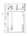
次に図20のフローチャートを用いて本発明の制御を説明する。ユーザーが原稿を読み込み送信または読み込み画像の格納処理を行う場合、操作部150に表示されている基本画面1501の「送信」ボタン1502を押下して送信設定画面1601を表示させ、送信方法などの諸設定を行う必要がある。送信設定画面1601の「電子メール」ボタン1602を押下した場合、電子メールアドレス設定画面1701が表示され、送信設定画面1601の「ボックスに保管」ボタン1603を押下した場合、ボックス保存設定画面1801が表示される。各設定画面で設定を行うと、送信設定画面1601の宛先表示1604は図19の宛先表示1902にように表示される(S2001)。
Next, the control of the present invention will be described using the flowchart of FIG. When the user scans and sends a document or stores a scanned image, the user presses the “Send”
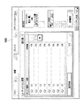
ここでユーザーが操作部150のスタートボタンを押下すると(S2002)、CPU1401は設定されている宛先を順番に検索し、プリンタ部300で出力する可能性のある画像を生成する宛先、すなわち像域情報が必要な宛先を検索する像域情報作成判定(S2003)を各々の宛先に対して行う。すべての宛先に対して像域情報作成判定(S2003)が終了したら(S2004)、CPU1401は最終的に像域情報を作成する必要があるかどうかを判断し(S2005)、像域情報を作成する必要があると判断したときは、画像圧縮伸張部1405の圧縮伸張回路1406の設定を圧縮率が高くなるように行い(S2006)、同時に像域データバッファの出力を有効にする(S2007)。像域情報を作成する必要が無いと判断した場合には画像圧縮伸張部1405の圧縮伸張回路1406の設定を圧縮率が低くなるようにし(S2008)、同時に像域データバッファの出力を無効にする(S2009)。上記の処理を行った後CPU1401は原稿読み取り動作(S2010)を行い、次に画像蓄積処理(S2011)を行い、ユーザーの設定した宛先から判断した圧縮率と像域情報の可否の設定を反映した画像データをHD1430に蓄積する。
When the user presses the start button of the operation unit 150 (S2002), the
HD1430に格納された画像データをプリンタ装置300に出力する場合、HD1430に格納された圧縮画像データと像域情報をバスコントローラ1426を介してDRAM1403に転送し、DRAM1403から画像圧縮伸張部1405を介して画像データと像域情報を伸張し、GraphicProcessor1419の画像回転部1421、画像変倍部1422、色空間変換部1423を介して画像処理を行う。さらに、プリンタI/F145のLOG変換部701、モアレ除去部702、UCR&マスキング部703、γ補正部704、フィルタ部705でプリントに最適な処理を施した上でコネクタ147を介してプリンタ部300へ出力する。このとき像域情報はUCR&マスキング部703とフィルタ部705で参照され、画像データに最適な処理が施される。
When outputting the image data stored in the
HD1430に格納された画像データをLAN400を介して、LAN400に接続されているPC411、PC412に送信する場合、HD1430に格納された圧縮画像データをバスコントローラ1426を介してDRAM1403に転送する。その後DRAM1403から画像圧縮伸張部1405を介して画像データを伸張し、GraphicProcessor1419の画像回転部1421、画像変倍部1422、色空間変換部1423、画像二値化部1425において画像処理を行った後、再度画像圧縮伸張回路1405で圧縮を行い、Network Controller121を介してLAN400に接続されているPC411、PC412に送信する。
When transmitting the image data stored in the
以上により、ユーザーが設定した処理内容に従って、効率的に画像メモリ領域を使用することが可能となる。
(第2実施形態)
次にLAN400上のPC411、またはPC412からの画像読み取り要求を受けて、画像データを生成、送信する場合の処理について、図22に示すフローチャートを用いて説明する。PC411またはPC412からの画像読み取りの要求はLAN400上からNetwork Controller121を介してCPU1401で受信される。CPU1401はLAN400上のPC411またはPC412からの画像読み取り要求を検知した場合(S2201)、操作部150上に表示されている操作画面1501の「リモートスキャナ」ボタン1503が押下されており、かつ「リモートスキャナ」ボタン1503が押下されることにより操作部150上に表示される操作画面2101の「オンライン」ボタン2102が押下されていることを確認する(S2202)。「オンライン」ボタン2102が押下されている場合、CPU1401は画像圧縮伸張部1405の像域データバッファ1417の出力を無効にし(S2203)、同時に圧縮伸張回路1406の圧縮率の設定を圧縮率が低くなるように設定する(S2204)。
As described above, the image memory area can be efficiently used in accordance with the processing content set by the user.
(Second Embodiment)
Next, a process for generating and transmitting image data in response to an image reading request from
上記の処理を行った後、CPU1401は原稿読み取り動作(S2205)を行い、次に画像蓄積処理(S2206)を行い、HD1430に圧縮された画像データが保存された後、NetworkController121を用いてHD1430に蓄積されている圧縮された画像データをLAN400上のPC411、PC412に送信する(S2207)。
After performing the above processing, the
以上により、LANに接続したPC等から送信を指示された画像データにおいては、像域情報を生成しないことが自動的に判断されるので、より低い圧縮率で圧縮されてより良好なデータを提供するようにすることができる。 As described above, in image data instructed to be transmitted from a PC connected to the LAN, it is automatically determined that image area information is not generated, so that it is compressed at a lower compression rate to provide better data. To be able to.
110 制御装置
140 スキャナI/F
145 プリンタI/F
150 操作部
200 リーダー部(画像入力装置)
210 スキャナユニット
211 プラテンガラス
212 ランプ
213 光学ユニット
214、215、216 ミラー
217 レンズ
218 CCDイメージセンサ
222 画像処理部
250 原稿給紙ユニット
300 プリンタ部(画像出力装置)
310 給紙ユニット
313、314、315、316 レーザ発光部
317 レーザドライバ
320 マーキングユニット
330 排紙ユニット
333 レジストローラ
335 定着部
336 排出ローラ
352 プリンタ画像処理部
360、361 用紙カセット
400 ネットワーク
401 クランプ&Amp.&S/H&A/D部
402 シェーディング部
411、412ホストコンピュータ
501 フィルタ
502 回路
503 色判定部
504 カウンタ
507〜510 レジスタ
601 つなぎ&MTF補正部
602 入力マスキング部
603 ACSカウント部
701 LOG変換部
702 モアレ除去部
703 UCR&マスキング部
704 γ補正部704
705 フィルタ部
1301 スキャナI/F
1302 リーダー部
1303 画像データ信号線
1304 つなぎ&MTF補正部
1305 入力マスキング部
1307 フィルタ
1308 色判定部
1309 像域分離部
1314 ACS判定領域検出回路
1315 ACSカウンタ
1401 CPU
1403 DRAM
1404 SRAM
1405 画像圧縮伸張部
1406 圧縮回路
1417 像域データバッファ
1418 画像データバッファ
1426 バスコントローラ
1427 I/O制御部
1428 コネクタ
1429 HDドライブ
1430 HD
110
145 Printer I / F
150
210
310
705
1302
1403 DRAM
1404 SRAM
1405 Image compression /
Claims (5)
前記画像データから像域情報を生成する像域情報生成手段と、
前記生成した画像データを圧縮する圧縮手段と、
前記圧縮された画像データを記憶する記憶手段と、
前記記憶された画像データを送信する宛先を設定する設定手段と、
前記設定された宛先がプリンタの宛先であるか、コンピュータの宛先であるかを判定する判定手段と、
前記判定手段により宛先がコンピュータの宛先であると判定した場合、宛先がプリンタの宛先であると判定した場合の圧縮率よりも低い圧縮率で前記圧縮手段が画像データを圧縮し、および前記像域生成手段が、前記像域情報を生成しないように制御する制御手段と
を備えたことを特徴とする像域情報生成装置。 Reading means for reading image data;
Image area information generating means for generating image area information from the image data;
Compression means for compressing the generated image data;
Storage means for storing the compressed image data;
Setting means for setting a destination for transmitting the stored image data;
Determination means for determining whether the set destination is a printer destination or a computer destination ;
When the determination unit determines that the destination is a computer destination, the compression unit compresses the image data at a compression rate lower than the compression rate when the destination is determined to be a printer destination , and the image area An image area information generating apparatus comprising: control means for controlling the generating means so as not to generate the image area information .
前記画像データから像域情報を生成する像域情報生成ステップと、
前記生成した画像データを圧縮する圧縮ステップと、
前記圧縮された画像データを記憶する記憶ステップと、
前記記憶された画像データを送信する宛先を設定する設定ステップと、
前記設定された宛先がプリンタの宛先であるか、コンピュータの宛先であるかを判定する判定ステップと、
前記判定ステップにおいて宛先がコンピュータの宛先であると判定した場合、前記圧縮ステップにおいて、宛先がプリンタの宛先であると判定した場合の圧縮率よりも低い圧縮率で画像データを圧縮し、および前記像域情報生成ステップにおいて、該像域情報を生成しないように制御する制御ステップと
を備えたことを特徴とする像域情報生成方法。 A reading step for reading image data;
An image area information generating step for generating image area information from the image data;
A compression step of compressing the generated image data;
A storage step of storing the compressed image data;
A setting step for setting a destination to which the stored image data is transmitted;
A determination step of determining whether the set destination is a printer destination or a computer destination ;
If the destination in the determination step has determined that the computer destination, in said compression step, to compress the image data at a low compression ratio than the compression rate when the destination is determined to be the destination of the printer, and the image An image area information generation method comprising: a control step for controlling not to generate the image area information in the area information generation step .
画像データを読み取る読取ステップと、
前記画像データから像域情報を生成する像域情報生成ステップと、
前記生成した画像データを圧縮する圧縮ステップと、
前記圧縮された画像データを記憶する記憶ステップと、
前記記憶された画像データを送信する宛先を設定する設定ステップと、
前記設定された宛先がプリンタの宛先であるか、コンピュータの宛先であるかを判定する判定ステップと、
前記判定ステップにおいて宛先がコンピュータの宛先であると判定した場合、前記圧縮ステップにおいて、宛先がプリンタの宛先であると判定した場合の圧縮率よりも低い圧縮率で画像データを圧縮し、および前記像域情報生成ステップにおいて、前記像域情報を生成しないように制御する制御ステップと
を備えたことを特徴とするプログラム。 A computer, a program for executing the image area information generating method, the image region information generation method,
A reading step for reading image data;
An image area information generating step for generating image area information from the image data;
A compression step of compressing the generated image data;
A storage step of storing the compressed image data;
A setting step for setting a destination to which the stored image data is transmitted;
A determination step of determining whether the set destination is a printer destination or a computer destination ;
If the destination in the determination step has determined that the computer destination, in said compression step, to compress the image data at a low compression ratio than the compression rate when the destination is determined to be the destination of the printer, and the image And a control step for controlling not to generate the image area information in an area information generating step .
Priority Applications (5)
| Application Number | Priority Date | Filing Date | Title |
|---|---|---|---|
| JP2005064402A JP4498174B2 (en) | 2005-03-08 | 2005-03-08 | Image area information generating apparatus, image area information generating method, and program |
| KR1020060021273A KR100790664B1 (en) | 2005-03-08 | 2006-03-07 | Image processing apparatus and method |
| EP06110793.4A EP1701221B1 (en) | 2005-03-08 | 2006-03-07 | Image processing apparatus and method |
| US11/368,613 US7679768B2 (en) | 2005-03-08 | 2006-03-07 | Image processing apparatus and method |
| CNB2006100581772A CN100446537C (en) | 2005-03-08 | 2006-03-08 | Image processing apparatus and method |
Applications Claiming Priority (1)
| Application Number | Priority Date | Filing Date | Title |
|---|---|---|---|
| JP2005064402A JP4498174B2 (en) | 2005-03-08 | 2005-03-08 | Image area information generating apparatus, image area information generating method, and program |
Publications (3)
| Publication Number | Publication Date |
|---|---|
| JP2006253840A JP2006253840A (en) | 2006-09-21 |
| JP2006253840A5 JP2006253840A5 (en) | 2008-04-24 |
| JP4498174B2 true JP4498174B2 (en) | 2010-07-07 |
Family
ID=36764263
Family Applications (1)
| Application Number | Title | Priority Date | Filing Date |
|---|---|---|---|
| JP2005064402A Active JP4498174B2 (en) | 2005-03-08 | 2005-03-08 | Image area information generating apparatus, image area information generating method, and program |
Country Status (5)
| Country | Link |
|---|---|
| US (1) | US7679768B2 (en) |
| EP (1) | EP1701221B1 (en) |
| JP (1) | JP4498174B2 (en) |
| KR (1) | KR100790664B1 (en) |
| CN (1) | CN100446537C (en) |
Families Citing this family (6)
| Publication number | Priority date | Publication date | Assignee | Title |
|---|---|---|---|---|
| JP5139716B2 (en) * | 2007-05-16 | 2013-02-06 | キヤノン株式会社 | Image search apparatus and image search method |
| US8218467B2 (en) | 2008-09-15 | 2012-07-10 | Qualcomm Incorporated | Method and apparatus for optimizing idle mode stand-by time in a multicast system |
| JP2014197740A (en) * | 2013-03-29 | 2014-10-16 | セイコーエプソン株式会社 | Print control device and print control program |
| EP3063874B1 (en) | 2013-10-31 | 2018-10-10 | Thorlabs, Inc. | Multiple channel matching method |
| CN104089575B (en) * | 2014-07-02 | 2018-05-11 | 北京东方迈视测控技术有限公司 | Intelligent plane detector and detection method |
| KR102301940B1 (en) * | 2017-12-01 | 2021-09-14 | 삼성전자주식회사 | Method and apparatus for image fusion |
Citations (2)
| Publication number | Priority date | Publication date | Assignee | Title |
|---|---|---|---|---|
| JPH08317232A (en) * | 1995-05-22 | 1996-11-29 | Ricoh Co Ltd | Color image communication device |
| JP2004193721A (en) * | 2002-12-09 | 2004-07-08 | Sharp Corp | Read data transmission apparatus |
Family Cites Families (8)
| Publication number | Priority date | Publication date | Assignee | Title |
|---|---|---|---|---|
| US6041144A (en) * | 1991-09-17 | 2000-03-21 | Canon Kabushiki Kaisha | Image processing apparatus |
| US5566003A (en) * | 1992-01-21 | 1996-10-15 | Canon Kabushiki Kaisha | Image processing system in which the transmitter and receiver have different data resolutions and data is transmitted at the receiver resolution |
| JPH0916149A (en) * | 1995-04-28 | 1997-01-17 | Canon Inc | Character processor, character processing method, and memory |
| JP3526255B2 (en) | 1997-02-07 | 2004-05-10 | キヤノン株式会社 | Information processing apparatus, print control method, print control system, and storage medium |
| JP3865169B2 (en) * | 1997-11-28 | 2007-01-10 | ソニー株式会社 | COMMUNICATION TERMINAL DEVICE AND COMMUNICATION TERMINAL DEVICE CONTROL METHOD |
| JP3509767B2 (en) * | 2001-03-29 | 2004-03-22 | ミノルタ株式会社 | E-mail transmission device, method, program, and recording medium |
| JP4087256B2 (en) * | 2003-01-09 | 2008-05-21 | 株式会社リコー | Network facsimile apparatus, distribution method in network facsimile apparatus, and computer-readable recording medium storing program for executing the method |
| JP4001284B2 (en) * | 2003-03-11 | 2007-10-31 | 株式会社リコー | Image processing apparatus and image processing method |
-
2005
- 2005-03-08 JP JP2005064402A patent/JP4498174B2/en active Active
-
2006
- 2006-03-07 US US11/368,613 patent/US7679768B2/en active Active
- 2006-03-07 EP EP06110793.4A patent/EP1701221B1/en active Active
- 2006-03-07 KR KR1020060021273A patent/KR100790664B1/en active IP Right Grant
- 2006-03-08 CN CNB2006100581772A patent/CN100446537C/en active Active
Patent Citations (2)
| Publication number | Priority date | Publication date | Assignee | Title |
|---|---|---|---|---|
| JPH08317232A (en) * | 1995-05-22 | 1996-11-29 | Ricoh Co Ltd | Color image communication device |
| JP2004193721A (en) * | 2002-12-09 | 2004-07-08 | Sharp Corp | Read data transmission apparatus |
Also Published As
| Publication number | Publication date |
|---|---|
| KR20060099431A (en) | 2006-09-19 |
| EP1701221A3 (en) | 2006-09-27 |
| US7679768B2 (en) | 2010-03-16 |
| EP1701221A2 (en) | 2006-09-13 |
| CN1832529A (en) | 2006-09-13 |
| KR100790664B1 (en) | 2008-01-02 |
| JP2006253840A (en) | 2006-09-21 |
| CN100446537C (en) | 2008-12-24 |
| US20060203284A1 (en) | 2006-09-14 |
| EP1701221B1 (en) | 2017-05-31 |
Similar Documents
| Publication | Publication Date | Title |
|---|---|---|
| JP2004074561A (en) | Color image processing apparatus and image outputting method | |
| JP4498174B2 (en) | Image area information generating apparatus, image area information generating method, and program | |
| JP2004153638A (en) | Copying apparatus | |
| JP2004080601A (en) | Device, system, and method for processing image and control program | |
| JP2004094731A (en) | Image forming apparatus and its method | |
| JP2007166516A (en) | Operation display for multi-function system | |
| JP2004129067A (en) | Image forming method | |
| JP2004153568A (en) | Image forming device | |
| JP2005027037A (en) | Format conversion method and image processing apparatus | |
| JP2004153567A (en) | Image input/output device and control method therefor, image input/output system and control program | |
| JP2008022082A (en) | Image forming apparatus and control method thereof | |
| JP2007025255A (en) | Image forming apparatus | |
| JP2006224595A (en) | Printing system | |
| JP2003023537A (en) | Image processor | |
| JP2008017121A (en) | Image input and output device | |
| JP3720674B2 (en) | Image processing apparatus, image processing apparatus control method, and storage medium | |
| JP2004032256A (en) | Image processor, control method therefor, program and storage medium | |
| US20100321707A1 (en) | Image forming apparatus, method of controlling the same, and storage medium | |
| JP2004349858A (en) | Image processor and document duplicating apparatus using the same | |
| JP2007108942A (en) | Image processor | |
| JP2006116758A (en) | Image processor, image processing method, storage medium with computer readable program stored, and program | |
| JP2004128808A (en) | Method and apparatus for image processing | |
| JP2006159729A (en) | Image processing system | |
| JP2004214957A (en) | Image input/output device | |
| JP2007096695A (en) | Method and device for image processing, and computer program |
Legal Events
| Date | Code | Title | Description |
|---|---|---|---|
| A521 | Written amendment |
Free format text: JAPANESE INTERMEDIATE CODE: A523 Effective date: 20080310 |
|
| A621 | Written request for application examination |
Free format text: JAPANESE INTERMEDIATE CODE: A621 Effective date: 20080310 |
|
| A977 | Report on retrieval |
Free format text: JAPANESE INTERMEDIATE CODE: A971007 Effective date: 20100104 |
|
| A131 | Notification of reasons for refusal |
Free format text: JAPANESE INTERMEDIATE CODE: A131 Effective date: 20100108 |
|
| A521 | Written amendment |
Free format text: JAPANESE INTERMEDIATE CODE: A523 Effective date: 20100309 |
|
| TRDD | Decision of grant or rejection written | ||
| A01 | Written decision to grant a patent or to grant a registration (utility model) |
Free format text: JAPANESE INTERMEDIATE CODE: A01 Effective date: 20100409 |
|
| A01 | Written decision to grant a patent or to grant a registration (utility model) |
Free format text: JAPANESE INTERMEDIATE CODE: A01 |
|
| A61 | First payment of annual fees (during grant procedure) |
Free format text: JAPANESE INTERMEDIATE CODE: A61 Effective date: 20100413 |
|
| FPAY | Renewal fee payment (event date is renewal date of database) |
Free format text: PAYMENT UNTIL: 20130423 Year of fee payment: 3 |
|
| R150 | Certificate of patent or registration of utility model |
Ref document number: 4498174 Country of ref document: JP Free format text: JAPANESE INTERMEDIATE CODE: R150 Free format text: JAPANESE INTERMEDIATE CODE: R150 |
|
| FPAY | Renewal fee payment (event date is renewal date of database) |
Free format text: PAYMENT UNTIL: 20130423 Year of fee payment: 3 |
|
| FPAY | Renewal fee payment (event date is renewal date of database) |
Free format text: PAYMENT UNTIL: 20140423 Year of fee payment: 4 |