JP4494902B2 - Sound playback device - Google Patents
Sound playback device Download PDFInfo
- Publication number
- JP4494902B2 JP4494902B2 JP2004232905A JP2004232905A JP4494902B2 JP 4494902 B2 JP4494902 B2 JP 4494902B2 JP 2004232905 A JP2004232905 A JP 2004232905A JP 2004232905 A JP2004232905 A JP 2004232905A JP 4494902 B2 JP4494902 B2 JP 4494902B2
- Authority
- JP
- Japan
- Prior art keywords
- frequency
- information
- acoustic information
- low
- circuit
- Prior art date
- Legal status (The legal status is an assumption and is not a legal conclusion. Google has not performed a legal analysis and makes no representation as to the accuracy of the status listed.)
- Active
Links
- 230000006866 deterioration Effects 0.000 description 6
- 241000282412 Homo Species 0.000 description 4
- 230000007423 decrease Effects 0.000 description 4
- 238000010586 diagram Methods 0.000 description 4
- 230000035559 beat frequency Effects 0.000 description 3
- 230000000593 degrading effect Effects 0.000 description 2
- 230000015572 biosynthetic process Effects 0.000 description 1
- 238000006243 chemical reaction Methods 0.000 description 1
- 230000000694 effects Effects 0.000 description 1
- 238000009434 installation Methods 0.000 description 1
- 239000004973 liquid crystal related substance Substances 0.000 description 1
- 238000005070 sampling Methods 0.000 description 1
- 230000005236 sound signal Effects 0.000 description 1
- 238000003786 synthesis reaction Methods 0.000 description 1
- 230000002123 temporal effect Effects 0.000 description 1
Images


Description
この発明は、小口径のスピーカを用いて音響情報を再生する音響再生装置に関し、特にスピーカの最低共振周波数以下の音響情報を改善する音響再生装置に関する。 The present invention relates to an acoustic reproduction apparatus that reproduces acoustic information using a small-diameter speaker, and more particularly to an acoustic reproduction apparatus that improves acoustic information below the lowest resonance frequency of the speaker.
近年、テレビジョン受像器、ラジオカセットあるいはノート型パーソナルコンピュータ(PC)等の小型化に伴い、これら機器に取り付けられるスピーカも小型化が進んでいる。ここで、これらスピーカは、口径が小さく最低共振周波数が高いものとなる。そして、この最低共振周波数が人間の可聴域に含まれる場合には、その最低共振周波数以下の低域部分の音響情報に劣化が生じ、忠実な音響情報の再生が困難となる。 In recent years, with the miniaturization of television receivers, radio cassettes, notebook personal computers (PCs), etc., the speakers attached to these devices have also been miniaturized. Here, these speakers have a small diameter and a high minimum resonance frequency. When this lowest resonance frequency is included in the human audible range, the acoustic information in the low frequency region below the lowest resonance frequency is deteriorated, making it difficult to reproduce the faithful acoustic information.
他方、この低音域の音響情報の劣化を防止する為に、ラウドネス補償回路あるいはトーンコントロール回路と言った電気的に低音域を増幅する回路が用いられる。また、低音域の音響情報の周波数を2逓倍して最低共振周波数を越える周波数とし、この2逓倍された音響情報を低音域の音響情報と模擬することも行われる(例えば、特許文献1参照)。
しかしながら、上記背景技術によれば、低音域の音響情報を、良好な状態で再生することができない。すなわち、ラウドネス補償回路あるいはトーンコントロール回路と言った電気的に低音域を増幅する場合には、スピーカの低音域での出力音圧の低下を或る程度補償できるものの、著しい音圧の低下に対応するには困難が伴い、さらには音圧波形の歪みが不可避的に生じる。 However, according to the above background art, it is not possible to reproduce low-frequency acoustic information in a good state. In other words, when electrically amplifying the low frequency range, such as a loudness compensation circuit or tone control circuit, it is possible to compensate for a decrease in the output sound pressure in the low frequency range of the speaker to some extent, but it corresponds to a significant decrease in sound pressure. It is difficult to do so, and distortion of the sound pressure waveform inevitably occurs.
また、低音域の音響情報の周波数を2逓倍する場合には、最低共振周波数による劣化は受けないものの、2逓倍される音響情報を、低音域の音響情報と模擬しているだけなので正確な再生とは異なる。 In addition, when the frequency of the low-frequency sound information is doubled, the deterioration is not caused by the lowest resonance frequency, but the doubled sound information is only simulated with the low-frequency sound information, so that accurate reproduction is possible. Is different.
なお、携帯化のための小型化が著しい液晶テレビ、ラジオカセットおよびPC等では、スピーカの小型化が著しく、この低音域の音響情報の劣化は、特に目立つものとなる。
これらのことから、小口径のスピーカを用いる際にも、低音域の音響情報の劣化が生じない音響再生装置をいかに実現するかが重要となる。
Note that, in liquid crystal televisions, radio cassettes, PCs, and the like that are remarkably miniaturized for portability, the speakers are remarkably miniaturized, and the deterioration of the low-frequency acoustic information becomes particularly noticeable.
For these reasons, it is important how to realize a sound reproducing apparatus that does not cause deterioration of low-frequency sound information even when a small-diameter speaker is used.
この発明は、上述した背景技術による課題を解決するためになされたものであり、小口径のスピーカを用いる際にも、低音域の音響情報の劣化が生じない音響再生装置を提供することを目的とする。 The present invention has been made to solve the above-described problems caused by the background art, and an object of the present invention is to provide a sound reproducing device that does not cause deterioration of low-frequency sound information even when a small-diameter speaker is used. And
上述した課題を解決し、目的を達成するために、請求項1に記載の発明にかかる音響再生装置は、入力音響情報を入力する入力手段と、出力音響情報を音波に変換する小口径のスピーカと、前記入力音響情報から、前記スピーカの最低共振周波数を超える周波数の高域音響情報を抽出する高域通過フィルタと、前記入力音響情報から、前記最低共振周波数を越えない基本周波数からなる低域音響情報を抽出するバンドパスフィルタと、前記低域音響情報から、前記最低共振周波数を超える周波数で変調された前記基本周波数に相当する周期のうなりを発生させるうなり発生回路と、前記うなりの情報および前記高域音響情報を加算し、前記出力音響情報として前記スピーカに出力する加算出力手段と、を備える。 In order to solve the above-described problems and achieve the object, the sound reproducing apparatus according to the first aspect of the present invention includes an input means for inputting input sound information, and a small-diameter speaker for converting the output sound information into sound waves. A high-pass filter for extracting high-frequency acoustic information having a frequency exceeding the lowest resonance frequency of the speaker from the input acoustic information, and a low-frequency band consisting of a fundamental frequency not exceeding the minimum resonance frequency from the input acoustic information. A band-pass filter for extracting acoustic information; a beat generating circuit for generating a beat of a period corresponding to the fundamental frequency modulated at a frequency exceeding the lowest resonance frequency from the low-frequency acoustic information; Addition means for adding the high-frequency acoustic information and outputting the high-frequency acoustic information to the speaker as the output acoustic information.
この請求項1に記載の発明では、入力音響情報から、高域通過フィルタを用いてスピーカの最低共振周波数を超える周波数の高域音響情報を抽出し、また同じく入力音響情報から、バンドパスフィルタを用いて最低共振周波数を越えない基本周波数からなる低域音響情報を抽出し、この低域音響情報から、うなり発生回路を用いて最低共振周波数を超える周波数で変調された基本周波数に相当する周期のうなりを発生させ、加算出力手段を用いてうなりの情報および高域音響情報を加算し、出力音響情報としてスピーカに出力させる。 In the first aspect of the present invention, high-frequency acoustic information having a frequency exceeding the lowest resonance frequency of the speaker is extracted from the input acoustic information using a high-pass filter, and a band-pass filter is similarly extracted from the input acoustic information. The low frequency acoustic information consisting of the fundamental frequency not exceeding the lowest resonance frequency is extracted, and the period corresponding to the fundamental frequency modulated at a frequency exceeding the lowest resonance frequency using the beat generation circuit is extracted from this low frequency acoustic information. The beat is generated, the beat information and the high frequency sound information are added using the addition output means, and output as the output sound information to the speaker.
また、この発明にかかる音響再生装置は、前記うなり発生回路が、Nを2以上の整数として、前記低域音響情報を前記基本周波数のN逓倍にするN逓倍回路、前記低域音響情報を前記基本周波数のN+1逓倍にするN+1逓倍回路、並びに、前記N逓倍回路および前記N+1逓倍回路の出力を加算あるいは減算する加減算回路を備えることを特徴とする。 Also, the sound reproducing apparatus according to this invention, the beat generation circuit, as two or more integer N, N multiplying circuits for the low-frequency audio information to N multiplying said fundamental frequency, said low frequency acoustic information An N + 1 multiplication circuit for multiplying the fundamental frequency by N + 1, and an addition / subtraction circuit for adding or subtracting outputs of the N multiplication circuit and the N + 1 multiplication circuit are provided.
この発明では、うなり発生回路は、N逓倍回路により、低域音響情報を基本周波数のN逓倍にし、N+1逓倍回路により、低域音響情報を基本周波数のN+1逓倍にし、並びに、加減算回路により、N逓倍回路およびN+1逓倍回路の出力を加算あるいは減算する。 In this invention, beat generation circuit, the N multiplying circuit, a low-frequency acoustic information into N multiple of the fundamental frequency, the N + 1 multiplier circuit, the low frequency sound information to the (N + 1) multiplying the fundamental frequency, as well as, the addition and subtraction circuit, The outputs of the N multiplier circuit and the N + 1 multiplier circuit are added or subtracted.
また、請求項2に記載の発明にかかる音響再生装置は、請求項1において、前記N逓倍回路および前記N+1逓倍回路が、前記N逓倍された低域音響情報および前記N+1逓倍された低域音響情報を増幅する増幅器を備えることを特徴とする。 According to a second aspect of the present invention, there is provided the sound reproducing device according to the first aspect , wherein the N multiplication circuit and the N + 1 multiplication circuit are the N-multiplied low-frequency sound information and the N + 1-multiplied low-frequency sound. An amplifier for amplifying information is provided.
この請求項2に記載の発明では、N逓倍回路およびN+1逓倍回路は、増幅器により、N逓倍およびN+1逓倍された低域音響情報を増幅する。
また、請求項3に記載の発明にかかる音響再生装置は、請求項1または2おいて、前記加算出力手段が、前記加減算回路を含むことを特徴とする。
According to the second aspect of the present invention, the N multiplier circuit and the N + 1 multiplier circuit amplify the low frequency sound information that has been multiplied by N and N + 1 by the amplifier.
According to a third aspect of the present invention, there is provided the sound reproducing device according to the first or second aspect , wherein the addition output means includes the addition / subtraction circuit.
この請求項3に記載の発明では、加算出力手段に加減算回路を含ませる。
また、請求項4に記載の発明にかかる音響再生装置は、請求項1ないし3のいずれか1つにおいて、前記最低共振周波数が前記基本周波数の2倍を越えない際に、前記Nが2とされることを特徴とする。
この請求項4に記載の発明では、Nを2とする。
According to the third aspect of the present invention, the addition output means includes an addition / subtraction circuit.
The acoustic reproducing apparatus according to the invention of claim 4, in any one of
In the invention described in claim 4 , N is set to 2.
以上説明したように、請求項1に記載の発明によれば、入力音響情報から、高域通過フィルタを用いてスピーカの最低共振周波数を超える周波数の高域音響情報を抽出し、また同じく入力音響情報から、バンドパスフィルタを用いて最低共振周波数を越えない基本周波数からなる低域音響情報を抽出し、この低域音響情報から、うなり発生回路を用いて最低共振周波数を超える周波数で変調された基本周波数に相当する周期のうなりを発生させ、加算出力手段を用いてうなりの情報および高域音響情報を加算し、出力音響情報としてスピーカに出力させることとしているので、スピーカで低域音響情報を劣化させることなく、しかも基になる低域音響情報の音の高さおよび強さと同等の知覚を人間に生じさせる忠実な音響再生を行い、ひいてはスピーカの設置面積が小さい携帯用の音響機器等で、低音域で歪みの少ない品質の良い音を発生させることができる。
As described above, according to the invention described in
また、この発明によれば、うなり発生回路は、N逓倍回路により、低域音響情報を基本周波数のN逓倍にし、N+1逓倍回路により、低域音響情報を基本周波数のN+1逓倍にし、並びに、加減算回路により、N逓倍回路およびN+1逓倍回路の出力を加算あるいは減算することとしているので、低域音響情報を、基本周波数と一致するうなりを有し、また同時に最低共振周波数を越える周波数に変調させたものとすることができる。 Further, according to this invention, beat generation circuit, the N multiplying circuit, a low-frequency acoustic information into N multiple of the fundamental frequency, the N + 1 multiplier circuit, the low frequency sound information to the (N + 1) multiplying the fundamental frequency, and, Since the adder / subtracter circuit adds or subtracts the output of the N multiplier circuit and the N + 1 multiplier circuit, the low frequency sound information has a beat that matches the fundamental frequency and simultaneously modulates the frequency to a frequency exceeding the lowest resonance frequency. Can be.
請求項2に記載の発明によれば、N逓倍回路およびN+1逓倍回路は、増幅器により、N逓倍およびN+1逓倍された低域音響情報を増幅することとしているので、加算あるいは減算を行う際の逓倍波形の合成比率を制御し、同時に発生されるうなりの最大振幅を最適なものとすることができる。 According to the second aspect of the invention, the N multiplier circuit and the N + 1 multiplier circuit amplify the low frequency sound information multiplied by N and N + 1 by the amplifier. By controlling the waveform synthesis ratio, the maximum amplitude of beats generated simultaneously can be optimized.
請求項3に記載の発明によれば、加算出力手段に加減算回路を含ませることとしているので、簡易な回路構成とすることができる。
請求項4に記載の発明によれば、Nを2にすることとしているので、最低共振周波数を越えない範囲で、しかもこの最低共振周波数近傍に存在する低域音響情報のうなりを発生させることができる。
According to the third aspect of the present invention, since the addition / subtraction circuit is included in the addition output means, a simple circuit configuration can be achieved.
According to the invention described in claim 4 , since N is set to 2, it is possible to generate a beat of low-frequency acoustic information existing in the vicinity of the lowest resonance frequency in a range not exceeding the lowest resonance frequency. it can.
以下に添付図面を参照して、この発明にかかる音響再生装置を実施するための最良の形態について説明する。なお、これにより本発明が限定されるものではない。
まず、本実施の形態にかかる音響再生装置の全体構成について図1を用いて説明する。図1は、音響再生装置の全体構成を示すブロック図である。音響再生装置は、入力手段10、高域通過フィルタ1、バンドパスフィルタ2、うなり発生回路20、電力増幅器8およぼスピーカ9を含む。そして、さらにうなり発生回路20は、2逓倍回路3、増幅器4、3逓倍回路5、増幅器6および加算出力手段7を含む。
The best mode for carrying out a sound reproducing apparatus according to the present invention will be described below with reference to the accompanying drawings. Note that the present invention is not limited thereby.
First, the overall configuration of the sound reproducing device according to the present embodiment will be described with reference to FIG. FIG. 1 is a block diagram showing the overall configuration of the sound reproducing apparatus. The sound reproduction device includes an input means 10, a high-
入力手段10は、テーププレーヤ、CDプレーヤあるいはFMチューナ等のオーディオソースから出力されるオーディオ信号を含む入力音響情報を入力する手段である。この入力音響情報には、人間の可聴範囲に相当する概ね20〜20KHzの信号が含まれている。 The input means 10 is means for inputting input acoustic information including an audio signal output from an audio source such as a tape player, a CD player, or an FM tuner. This input acoustic information includes a signal of approximately 20 to 20 kHz corresponding to the human audible range.
スピーカ9は、電気信号として入力される出力音響情報を、音波に変換する小口径のスピーカである。スピーカ9は、小型のテレビジョン受像器、携帯型のラジオカセットあるいはPC等の、スピーカ部分に大きな設置面積の確保が困難な機器で用いられる。 The speaker 9 is a small-diameter speaker that converts output acoustic information input as an electrical signal into a sound wave. The speaker 9 is used in a device in which it is difficult to secure a large installation area in the speaker portion, such as a small television receiver, a portable radio cassette, or a PC.
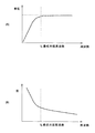
ここで、スピーカ9は、図2に示す音響特性を有する。図2(A)は、縦軸を出力音圧、横軸を入力信号の周波数とする音圧周波数特性である。ここで、スピーカ9の出力音圧は、最低共振周波数f0以下の周波数で急激に低下する。また、図2(B)は、縦軸を出力波形の歪み、横軸を入力信号の周波数とする歪み周波数特性である。図2(A)と同様に、スピーカ9の出力波形の歪みは、最低共振周波数f0以下の周波数で急激に増加する。 Here, the speaker 9 has the acoustic characteristics shown in FIG. FIG. 2A shows sound pressure frequency characteristics where the vertical axis represents the output sound pressure and the horizontal axis represents the frequency of the input signal. Here, the output sound pressure of the speaker 9 rapidly decreases at a frequency equal to or lower than the lowest resonance frequency f 0 . FIG. 2B shows distortion frequency characteristics in which the vertical axis indicates distortion of the output waveform and the horizontal axis indicates the frequency of the input signal. Similar to FIG. 2A, the distortion of the output waveform of the speaker 9 increases rapidly at a frequency equal to or lower than the lowest resonance frequency f 0 .
また、図2で示される最低共振周波数f0は、スピーカ9で使用される振動板の口径が小さくなるとf0が高くなる傾向を有する。ここで、小口径のスピーカの場合には、最低共振周波数f0は、100Hz程度の大きさのものとなり、人間の可聴範囲の下限である20Hzを越えるものとなる。なお、この場合、入力音響情報をスピーカ9に直接入力すると、入力音響情報の低域部分は、図2(A)および(B)で示す音圧の低下および歪みの影響により劣化した形で出力される。 Moreover, the lowest resonance frequency f 0 shown in FIG. 2, has a tendency to diameter of the diaphragm used in the speaker 9 is higher f 0 becomes smaller. Here, in the case of a small-diameter speaker, the minimum resonance frequency f 0 has a magnitude of about 100 Hz and exceeds 20 Hz, which is the lower limit of the human audible range. In this case, when the input sound information is directly input to the speaker 9, the low frequency portion of the input sound information is output in a form deteriorated due to the decrease in sound pressure and the influence of distortion shown in FIGS. Is done.
高域通過フィルタ1は、カットオフ周波数を上述した最低共振周波数f0の近傍に有する、高域通過型のフィルタである。これにより、入力手段10に入力された入力音響情報から、スピーカ9の音響特性による劣化を受けない高域音響情報のみを抽出する。
The high-
バンドパスフィルタ2は、バンドパス部が上述した最低共振周波数f0を越えない範囲に存在するバンドパス型のフィルタである。これにより、入力手段10に入力された入力音響情報から、特にスピーカ9の音響特性による劣化を受ける低域音響情報のみを抽出する。なお、バンドパス部の中心周波数を基本周波数と称し、低域音響情報は主としてこの基本周波数成分から構成される。
The
うなり発生回路20は、低域音響情報から、低域音響情報の基本周波数と一致する周波数のうなりを発生する。ここで、うなり発生回路20の2逓倍回路3および3逓倍回路5は、バンドパスフィルタ2により抽出された低域音響情報の基本周波数を2逓倍および3逓倍とする2逓倍波形および3逓倍波形を形成する。図3は、この逓倍回路の一例を示すブロック図である。なお、図3では2逓倍回路3を用いて説明しているが、3逓倍回路、さらにはNを2以上の整数として、N逓倍回路の場合も全く同様である。
The beat generation circuit 20 generates a beat of a frequency that matches the fundamental frequency of the low-frequency acoustic information from the low-frequency acoustic information. Here, the
図3の2逓倍回路3は、A/D変換器31、書き込み部32、波形メモリ33、読み出し部34およびD/A変換器35を含む。A/D変換器31は、バンドパスフィルタ2からの低域音響情報をA/D(Analog To Digital)変換する。この際、サンプリング周期tは、基本周波数の低域音響情報を忠実に再現するように、基本周波数をf1として、t≦1/(2f1)となるように設定される。
3 includes an A /
書き込み部32は、A/D変換された低域音響情報を、波形メモリ33に読み込む。ここで、波形メモリ33は、低域音響情報の2周期分に相当する波形情報の格納領域を有し、書き込み部32は、この格納領域に繰り返し低域音響情報を書き込む。
The
読み出し部34は、波形メモリ33から低域音響情報を読み出し、D/A変換器35に出力する。ここで、読み出し部34は、書き込み速度の2倍速での読み出しを、低域音響情報をなす基本波形の1周期ごとに2度の読み出しを繰り返しつつ行う。なお、同等の効果は、書き込み速度と同一の速度での読み出しを、波形メモリ33からの基本波形の読み出しを1つおきに間引いて行うことによっても得ることができる。
The reading unit 34 reads the low-frequency acoustic information from the
D/A変換器35は、読み出し部34から読み出された低域音響情報をD/A変換し、アナログ情報として増幅器4へ出力する。この際、読み出し部34は、書き込み部32の2倍速で読み出しを行っているので、低域音響情報は基本周波数の2倍となる。なお、読み出し部34を書き込み部32のN倍速で読み出すことにより、N逓倍波形の生成を行うN逓倍回路も同様に構成することができる。
The D / A converter 35 D / A converts the low frequency sound information read from the reading unit 34 and outputs the analog information to the amplifier 4. At this time, since the reading unit 34 performs reading at twice the speed of the
図1に戻り、増幅器4および6は、2逓倍回路3および3逓倍回路5の出力を増幅する。これにより、2逓倍回路3および3逓倍回路5の出力波形の振幅を微調節し、後述するうなりの最大振幅を調節する。
Returning to FIG. 1, the amplifiers 4 and 6 amplify the outputs of the
加算出力手段7は、高域通過フィルタ1からの高域音響情報、2逓倍回路3からの2逓倍波形および3逓倍回路5からの3逓倍波形を加算し、電力増幅器8に出力する。ここで、加算出力手段7は、機能的には、うなり発生回路20に属する2逓倍波形および3逓倍波形を加算あるいは減算してうなりを発生する加減算回路部と、このうなりの情報をさらに高域音響情報に加算する部分とからなる。なお、このうなりの情報については、後に詳述する。
The addition output means 7 adds the high-frequency acoustic information from the high-
電力増幅器8は、加算出力手段7で再合成された高域音響情報および低域音響情報を、電力増幅してスピーカ9が音波を発するに適したパワーとし、スピーカ9に出力する。
つづいて、本実施の形態にかかる音響再生装置の動作について説明する。入力手段10から入力された人間の可聴範囲の周波数帯域を有する音響情報は、高域通過フィルタ1およびバンドパスフィルタ2により、スピーカ9により劣化されない高域音響情報およびスピーカ9により劣化する低域音響情報に分離される。
The power amplifier 8 amplifies the high frequency sound information and the low frequency sound information re-synthesized by the addition output means 7 to a power suitable for the speaker 9 to emit sound waves, and outputs the power to the speaker 9.
Next, the operation of the sound reproduction device according to this embodiment will be described. The acoustic information having the frequency band of the human audible range input from the input means 10 is high-frequency acoustic information that is not deteriorated by the speaker 9 and low-frequency sound that is deteriorated by the speaker 9 by the high-
図4(A)は、バンドパスフィルタ2により分離される、概ね単一の基本周期Tあるいはこの基本周期の逆数である基本周波数f1の基本波よりなる低域音響情報の例である。なお、図4(A)〜(D)は、横軸が時間、縦軸が音圧の振幅を現す。ここで、図4(A)に示す基本波の最大振幅aは、周期ごとに変化しうるものであり、低域音響情報の時間的変化を現す。
FIG. 4A shows an example of low-frequency acoustic information composed of a fundamental wave having a fundamental frequency f 1 which is separated by the
その後、低域音響情報は、2逓倍回路3および3逓倍回路5により、周波数が2逓倍および3逓倍される。図4(B)および(C)は、図4(A)に示す基本波から派生される2逓倍波形および3逓倍波形の例であり、各々周期がT/2およびT/3となる。ここで、これら2逓倍波形および3逓倍波形は、増幅器4および6で振幅調整された後に加算あるいは減算される。
Thereafter, the frequency of the low-frequency acoustic information is doubled and tripled by the
その後、2逓倍波形および3逓倍波形は、加算出力手段7により、加算あるいは減算される。図4(D)は、図4(B)および(C)に示す2逓倍波形および3逓倍波形を、加算して生成されるうなり波形の例である。 Thereafter, the doubled waveform and the tripled waveform are added or subtracted by the addition output means 7. FIG. 4D is an example of a beat waveform generated by adding the doubled waveform and the tripled waveform shown in FIGS. 4B and 4C.
ここで、うなり現象について若干の説明を行う。周波数が近似して異なる2つの音波が加算あるいは減算されると、相互の振幅関係の変化によりうなりを生じる。この異なる2つの音波の周波数をfa並びにfbとすると、うなりの周波数fは、
f=|fa−fb|
で表される。
Here, the beat phenomenon will be described briefly. When two sound waves with different frequencies are added or subtracted, a beat is caused by a change in the mutual amplitude relationship. If the frequencies of the two different sound waves are fa and fb, the beat frequency f is
f = | fa−fb |
It is represented by
従って、図4(B)に示す2逓倍波形の周波数をfa、図4(C)に示す3逓倍波形の周波数をfbとすると、図4(D)に示されるうなり波形のうなり周波数fは、
f=|fa−fb|=|2f1−3f1|=f1
となり、低域音響情報を形成する基本波の基本周波数f1と一致する。言い換えれば、うなり周期は、基本波の基本周期Tと一致する。なお、このうなり波形は、スピーカ9の最低共振周波数f0を超えるfaおよびfbで構成されているので、スピーカ9により劣化されることはない。
Therefore, if the frequency of the double waveform shown in FIG. 4B is fa and the frequency of the triple waveform shown in FIG. 4C is fb, the beat frequency f of the beat waveform shown in FIG.
f = | fa−fb | = | 2f 1 -3f 1 | = f 1
And coincides with the fundamental frequency f 1 of the fundamental wave forming the low-frequency acoustic information. In other words, the beat period coincides with the fundamental period T of the fundamental wave. Since the beat waveform is composed of fa and fb exceeding the lowest resonance frequency f 0 of the speaker 9, the beat waveform is not deteriorated by the speaker 9.
また、図4(D)に示すうなり波形のうなりの最大振幅hは、このうなり波形が低域音響情報である図4(A)の基本波から形成されたものであるので、基本波の最大振幅aと、
h∝a
の関係にある。従って、最大振幅aの時間変化に伴い、最大振幅hも変化し、最大振幅hは低域音響情報を反映したものとなる。
Further, the maximum amplitude h of the beat waveform shown in FIG. 4 (D) is formed from the fundamental wave of FIG. 4 (A), which is the low-frequency acoustic information, and thus the maximum of the fundamental wave. Amplitude a;
h∝a
Are in a relationship. Therefore, the maximum amplitude h also changes with the time change of the maximum amplitude a, and the maximum amplitude h reflects the low-frequency acoustic information.
その後、このうなり波形は、高域音響情報と加算された後に、スピーカ9で劣化を生じることなく音波として出力される。
なお、図4(D)に示すうなり波形は、図4(A)の示す様な正弦波状の基本波と同等の低音音響情報を、人間に知覚させると考えられる。すなわち、低音音響情報の音の高さは、物理的には正弦波状の基本波の基本周波数で示されるが、人間が知覚する音の高さは、高調波成分も含むうなりの周波数に比例する(非特許文献1)。従って、うなりの周期を基本波の基本周期と一致させることで、実質的に同じ音の高さとして人間に知覚させることができる。また、音の強さも、うなりの最大振幅hが基本波の最大振幅aの変化に連動して変化するので、基本波と同様に時間変化するものとして人間に知覚させることができる。
Thereafter, this beat waveform is output as a sound wave without being deteriorated by the speaker 9 after being added to the high frequency sound information.
Note that the beat waveform shown in FIG. 4D is considered to cause a human to perceive bass acoustic information equivalent to the sinusoidal fundamental wave as shown in FIG. That is, the pitch of the bass acoustic information is physically indicated by the fundamental frequency of the sinusoidal fundamental wave, but the pitch of the sound perceived by humans is proportional to the beat frequency including harmonic components. (Non-Patent Document 1). Therefore, by making the beat period coincide with the fundamental period of the fundamental wave, it is possible for humans to perceive it as substantially the same pitch. Also, since the maximum amplitude h of the beat changes in conjunction with the change of the maximum amplitude a of the fundamental wave, the intensity of the sound can be made to be perceived by humans as being changed with time similarly to the fundamental wave.
上述してきたように、本実施の形態では、入力音響情報から、スピーカ9により劣化される低域音響情報をバンドパスフィルタ2により分離抽出し、うなり発生回路20により、この低域音響情報の基本周波数を2倍および3倍した2逓倍波形および3逓倍波形の生成、並びに、加算あるいは減算を行い基本周波数に一致する周波数のうなりを生成し、低域の出力音響情報としてスピーカ9に出力することとしているので、スピーカ9で低域音響情報を劣化させることなく、しかも基になる低域音響情報の音の高さおよび強さと同等の知覚を人間に生じさせることができる。
As described above, in the present embodiment, the low-frequency acoustic information deteriorated by the speaker 9 is separated and extracted from the input acoustic information by the band-
1 高域通過フィルタ
2 バンドパスフィルタ
3 2逓倍回路
4、6 増幅器
5 3逓倍回路
7 加算出力手段
8 電力増幅器
9 スピーカ
10 入力手段
20 うなり発生回路
31 A/D変換器
32 書き込み部
33 波形メモリ
34 読み出し部
35 D/A変換器
DESCRIPTION OF
Claims (4)
出力音響情報を音波に変換する小口径のスピーカと、
前記入力音響情報から、前記スピーカの最低共振周波数を超える周波数の高域音響情報を抽出する高域通過フィルタと、
前記入力音響情報から、前記最低共振周波数を越えない基本周波数からなる低域音響情報を抽出するバンドパスフィルタと、
前記低域音響情報から、前記最低共振周波数を超える周波数で変調された前記基本周波数に相当する周期のうなりを発生させるうなり発生回路と、
前記うなりの情報および前記高域音響情報を加算し、前記出力音響情報として前記スピーカに出力する加算出力手段と、
を備え、
前記うなり発生回路は、Nを2以上の整数として、前記低域音響情報を前記基本周波数のN逓倍にするN逓倍回路、前記低域音響情報を前記基本周波数のN+1逓倍にするN+1逓倍回路、並びに、前記N逓倍回路および前記N+1逓倍回路の出力を加算あるいは減算する加減算回路を備えることを特徴とする音響再生装置。 An input means for inputting input acoustic information;
A small-diameter speaker that converts output acoustic information into sound waves;
A high-pass filter for extracting high-frequency acoustic information having a frequency exceeding the lowest resonance frequency of the speaker from the input acoustic information;
A bandpass filter for extracting low-frequency acoustic information consisting of a fundamental frequency not exceeding the lowest resonance frequency from the input acoustic information;
From the low-frequency acoustic information, a beat generating circuit for generating a beat of a period corresponding to the fundamental frequency modulated at a frequency exceeding the lowest resonance frequency,
An addition output means for adding the beat information and the high frequency sound information and outputting the information as the output sound information to the speaker;
Equipped with a,
The beat generating circuit is configured such that N is an integer equal to or greater than 2, and the low frequency acoustic information is multiplied by N of the fundamental frequency, an N multiplication circuit, and the low frequency acoustic information is multiplied by N + 1 of the fundamental frequency. and, an audio reproducing device you further comprising a subtracting circuit for adding or subtracting an output of said N multiplying circuit and the (N + 1) multiplying circuit.
Priority Applications (1)
| Application Number | Priority Date | Filing Date | Title |
|---|---|---|---|
| JP2004232905A JP4494902B2 (en) | 2004-08-10 | 2004-08-10 | Sound playback device |
Applications Claiming Priority (1)
| Application Number | Priority Date | Filing Date | Title |
|---|---|---|---|
| JP2004232905A JP4494902B2 (en) | 2004-08-10 | 2004-08-10 | Sound playback device |
Publications (2)
| Publication Number | Publication Date |
|---|---|
| JP2006054524A JP2006054524A (en) | 2006-02-23 |
| JP4494902B2 true JP4494902B2 (en) | 2010-06-30 |
Family
ID=36031731
Family Applications (1)
| Application Number | Title | Priority Date | Filing Date |
|---|---|---|---|
| JP2004232905A Active JP4494902B2 (en) | 2004-08-10 | 2004-08-10 | Sound playback device |
Country Status (1)
| Country | Link |
|---|---|
| JP (1) | JP4494902B2 (en) |
Families Citing this family (3)
| Publication number | Priority date | Publication date | Assignee | Title |
|---|---|---|---|---|
| JP4923939B2 (en) * | 2006-10-18 | 2012-04-25 | ソニー株式会社 | Audio playback device |
| US10805700B2 (en) | 2018-07-19 | 2020-10-13 | Lenovo (Singapore) Pte Ltd | Expansion device having a speaker |
| JP7379988B2 (en) * | 2019-09-20 | 2023-11-15 | 株式会社ソシオネクスト | Fundamental frequency determining device, pseudo bass processing device, fundamental frequency determining method, and acoustic processing method |
Citations (7)
| Publication number | Priority date | Publication date | Assignee | Title |
|---|---|---|---|---|
| JPH01186008A (en) * | 1988-01-20 | 1989-07-25 | Matsushita Electric Ind Co Ltd | Low frequency sound emphasis circuit |
| JPH08237800A (en) * | 1995-02-27 | 1996-09-13 | Matsushita Electric Ind Co Ltd | Low tone intensifying circuit |
| JPH11220793A (en) * | 1998-02-02 | 1999-08-10 | Matsushita Electric Ind Co Ltd | Low tone reinforcing circuit |
| JPH11234788A (en) * | 1998-02-10 | 1999-08-27 | Alpine Electron Inc | Audio equipment |
| JP2001245400A (en) * | 2000-03-01 | 2001-09-07 | Rohm Co Ltd | Ultralow frequency sound compensation system and acoustic device using it |
| JP2001306085A (en) * | 2000-04-25 | 2001-11-02 | Kyocera Corp | Device and method for reproduced sound generation |
| JP2004101797A (en) * | 2002-09-09 | 2004-04-02 | Matsushita Electric Ind Co Ltd | Sound signal processor and method therefor |
-
2004
- 2004-08-10 JP JP2004232905A patent/JP4494902B2/en active Active
Patent Citations (7)
| Publication number | Priority date | Publication date | Assignee | Title |
|---|---|---|---|---|
| JPH01186008A (en) * | 1988-01-20 | 1989-07-25 | Matsushita Electric Ind Co Ltd | Low frequency sound emphasis circuit |
| JPH08237800A (en) * | 1995-02-27 | 1996-09-13 | Matsushita Electric Ind Co Ltd | Low tone intensifying circuit |
| JPH11220793A (en) * | 1998-02-02 | 1999-08-10 | Matsushita Electric Ind Co Ltd | Low tone reinforcing circuit |
| JPH11234788A (en) * | 1998-02-10 | 1999-08-27 | Alpine Electron Inc | Audio equipment |
| JP2001245400A (en) * | 2000-03-01 | 2001-09-07 | Rohm Co Ltd | Ultralow frequency sound compensation system and acoustic device using it |
| JP2001306085A (en) * | 2000-04-25 | 2001-11-02 | Kyocera Corp | Device and method for reproduced sound generation |
| JP2004101797A (en) * | 2002-09-09 | 2004-04-02 | Matsushita Electric Ind Co Ltd | Sound signal processor and method therefor |
Also Published As
| Publication number | Publication date |
|---|---|
| JP2006054524A (en) | 2006-02-23 |
Similar Documents
| Publication | Publication Date | Title |
|---|---|---|
| US20060159283A1 (en) | Method and apparatus for audio bass enhancement | |
| JP4371268B2 (en) | Directional speaker driving method and directional speaker | |
| US8873763B2 (en) | Perception enhancement for low-frequency sound components | |
| KR101310231B1 (en) | Apparatus and method for enhancing bass | |
| JP4668415B2 (en) | Low frequency audio enhancement system | |
| US8000824B2 (en) | Audio reproducing apparatus | |
| US8204239B2 (en) | Audio processing method and audio processing apparatus | |
| JP5074115B2 (en) | Acoustic signal processing apparatus and acoustic signal processing method | |
| JP2002524996A5 (en) | ||
| JP2008085412A (en) | Audio reproducing device | |
| US20080267426A1 (en) | Device for and a Method of Audio Data Processing | |
| KR101329308B1 (en) | Method for enhancing Bass of Audio signal and apparatus therefore, Method for calculating fundamental frequency of audio signal and apparatus therefor | |
| JP3386618B2 (en) | Sound reproduction device | |
| JP4494902B2 (en) | Sound playback device | |
| WO2010090228A1 (en) | Sound reproduction device and sound reproduction system | |
| JP2008236198A (en) | Modulator for super-directional speaker | |
| WO2000002416A1 (en) | Sound reproducing device | |
| KR100556870B1 (en) | Mobile communication terminal included low-pitched sound boost circuit | |
| JPS62232298A (en) | Very low-frequency sound reproducing device | |
| JP2008304670A (en) | Electronic sound source device | |
| JP3155287U (en) | Audio FM modulation amplifier | |
| JP5697921B2 (en) | Demagnetizer and degaussing method | |
| JP2001036984A (en) | Acoustic reproducing device | |
| JP2012160811A (en) | Audio apparatus | |
| Aarts | Methods to improve the sound reproduction of limited size systems |
Legal Events
| Date | Code | Title | Description |
|---|---|---|---|
| A621 | Written request for application examination |
Free format text: JAPANESE INTERMEDIATE CODE: A621 Effective date: 20070724 |
|
| A131 | Notification of reasons for refusal |
Free format text: JAPANESE INTERMEDIATE CODE: A131 Effective date: 20090512 |
|
| A521 | Request for written amendment filed |
Free format text: JAPANESE INTERMEDIATE CODE: A523 Effective date: 20090713 |
|
| TRDD | Decision of grant or rejection written | ||
| A01 | Written decision to grant a patent or to grant a registration (utility model) |
Free format text: JAPANESE INTERMEDIATE CODE: A01 Effective date: 20100406 |
|
| A01 | Written decision to grant a patent or to grant a registration (utility model) |
Free format text: JAPANESE INTERMEDIATE CODE: A01 |
|
| A61 | First payment of annual fees (during grant procedure) |
Free format text: JAPANESE INTERMEDIATE CODE: A61 Effective date: 20100408 |
|
| R150 | Certificate of patent or registration of utility model |
Free format text: JAPANESE INTERMEDIATE CODE: R150 Ref document number: 4494902 Country of ref document: JP Free format text: JAPANESE INTERMEDIATE CODE: R150 |
|
| FPAY | Renewal fee payment (event date is renewal date of database) |
Free format text: PAYMENT UNTIL: 20130416 Year of fee payment: 3 |
|
| FPAY | Renewal fee payment (event date is renewal date of database) |
Free format text: PAYMENT UNTIL: 20140416 Year of fee payment: 4 |
|
| S531 | Written request for registration of change of domicile |
Free format text: JAPANESE INTERMEDIATE CODE: R313531 |
|
| R350 | Written notification of registration of transfer |
Free format text: JAPANESE INTERMEDIATE CODE: R350 |
|
| R250 | Receipt of annual fees |
Free format text: JAPANESE INTERMEDIATE CODE: R250 |
|
| R250 | Receipt of annual fees |
Free format text: JAPANESE INTERMEDIATE CODE: R250 |
|
| R250 | Receipt of annual fees |
Free format text: JAPANESE INTERMEDIATE CODE: R250 |
|
| R250 | Receipt of annual fees |
Free format text: JAPANESE INTERMEDIATE CODE: R250 |
|
| R250 | Receipt of annual fees |
Free format text: JAPANESE INTERMEDIATE CODE: R250 |
|
| R250 | Receipt of annual fees |
Free format text: JAPANESE INTERMEDIATE CODE: R250 |
|
| R250 | Receipt of annual fees |
Free format text: JAPANESE INTERMEDIATE CODE: R250 |
|
| R250 | Receipt of annual fees |
Free format text: JAPANESE INTERMEDIATE CODE: R250 |