JP4490619B2 - Polarization-maintaining fiber, fiber laser, and fiber amplifier - Google Patents
Polarization-maintaining fiber, fiber laser, and fiber amplifier Download PDFInfo
- Publication number
- JP4490619B2 JP4490619B2 JP2002072975A JP2002072975A JP4490619B2 JP 4490619 B2 JP4490619 B2 JP 4490619B2 JP 2002072975 A JP2002072975 A JP 2002072975A JP 2002072975 A JP2002072975 A JP 2002072975A JP 4490619 B2 JP4490619 B2 JP 4490619B2
- Authority
- JP
- Japan
- Prior art keywords
- fiber
- cladding
- polarization
- mode
- laser
- Prior art date
- Legal status (The legal status is an assumption and is not a legal conclusion. Google has not performed a legal analysis and makes no representation as to the accuracy of the status listed.)
- Expired - Fee Related
Links
Images


Classifications
-
- H—ELECTRICITY
- H01—ELECTRIC ELEMENTS
- H01S—DEVICES USING THE PROCESS OF LIGHT AMPLIFICATION BY STIMULATED EMISSION OF RADIATION [LASER] TO AMPLIFY OR GENERATE LIGHT; DEVICES USING STIMULATED EMISSION OF ELECTROMAGNETIC RADIATION IN WAVE RANGES OTHER THAN OPTICAL
- H01S3/00—Lasers, i.e. devices using stimulated emission of electromagnetic radiation in the infrared, visible or ultraviolet wave range
- H01S3/05—Construction or shape of optical resonators; Accommodation of active medium therein; Shape of active medium
- H01S3/06—Construction or shape of active medium
- H01S3/063—Waveguide lasers, i.e. whereby the dimensions of the waveguide are of the order of the light wavelength
- H01S3/067—Fibre lasers
- H01S3/06708—Constructional details of the fibre, e.g. compositions, cross-section, shape or tapering
- H01S3/06712—Polarising fibre; Polariser
-
- H—ELECTRICITY
- H01—ELECTRIC ELEMENTS
- H01S—DEVICES USING THE PROCESS OF LIGHT AMPLIFICATION BY STIMULATED EMISSION OF RADIATION [LASER] TO AMPLIFY OR GENERATE LIGHT; DEVICES USING STIMULATED EMISSION OF ELECTROMAGNETIC RADIATION IN WAVE RANGES OTHER THAN OPTICAL
- H01S3/00—Lasers, i.e. devices using stimulated emission of electromagnetic radiation in the infrared, visible or ultraviolet wave range
- H01S3/05—Construction or shape of optical resonators; Accommodation of active medium therein; Shape of active medium
- H01S3/06—Construction or shape of active medium
- H01S3/063—Waveguide lasers, i.e. whereby the dimensions of the waveguide are of the order of the light wavelength
- H01S3/067—Fibre lasers
- H01S3/06708—Constructional details of the fibre, e.g. compositions, cross-section, shape or tapering
- H01S3/06729—Peculiar transverse fibre profile
-
- H—ELECTRICITY
- H01—ELECTRIC ELEMENTS
- H01S—DEVICES USING THE PROCESS OF LIGHT AMPLIFICATION BY STIMULATED EMISSION OF RADIATION [LASER] TO AMPLIFY OR GENERATE LIGHT; DEVICES USING STIMULATED EMISSION OF ELECTROMAGNETIC RADIATION IN WAVE RANGES OTHER THAN OPTICAL
- H01S3/00—Lasers, i.e. devices using stimulated emission of electromagnetic radiation in the infrared, visible or ultraviolet wave range
- H01S3/09—Processes or apparatus for excitation, e.g. pumping
- H01S3/091—Processes or apparatus for excitation, e.g. pumping using optical pumping
- H01S3/094—Processes or apparatus for excitation, e.g. pumping using optical pumping by coherent light
- H01S3/094003—Processes or apparatus for excitation, e.g. pumping using optical pumping by coherent light the pumped medium being a fibre
- H01S3/094019—Side pumped fibre, whereby pump light is coupled laterally into the fibre via an optical component like a prism, or a grating, or via V-groove coupling
-
- H—ELECTRICITY
- H01—ELECTRIC ELEMENTS
- H01S—DEVICES USING THE PROCESS OF LIGHT AMPLIFICATION BY STIMULATED EMISSION OF RADIATION [LASER] TO AMPLIFY OR GENERATE LIGHT; DEVICES USING STIMULATED EMISSION OF ELECTROMAGNETIC RADIATION IN WAVE RANGES OTHER THAN OPTICAL
- H01S3/00—Lasers, i.e. devices using stimulated emission of electromagnetic radiation in the infrared, visible or ultraviolet wave range
- H01S3/10—Controlling the intensity, frequency, phase, polarisation or direction of the emitted radiation, e.g. switching, gating, modulating or demodulating
- H01S3/11—Mode locking; Q-switching; Other giant-pulse techniques, e.g. cavity dumping
- H01S3/1106—Mode locking
- H01S3/1112—Passive mode locking
- H01S3/1115—Passive mode locking using intracavity saturable absorbers
- H01S3/1118—Semiconductor saturable absorbers, e.g. semiconductor saturable absorber mirrors [SESAMs]; Solid-state saturable absorbers, e.g. carbon nanotube [CNT] based
Description
【0001】
【産業上の利用分野】
本発明の分野及び概説
本発明は、単一偏光光ファイバ、すなわち、強い偏光保持あるいは偏光保持特性を備えている光ファイバと、希土類をドープした同じものの変形で形成されるファイバレーザと、に関する。
【0002】
本発明によれば、理想的な偏光保持光ファイバは、様々な代替技術で作られる。一実施形態によれば、ファイバは、ファイバコア内の応力の減少を通しての偏光モード結合を最小にするべくファイバ径の増加による外面的曲げ及び温度変化に対して、偏光不感受性にされる。あるいは、偏光モード結合は、ファイバ−クラッド界面での応力を最小にするべく特殊なクラッド技術によって減らされる。応力誘起技術は、ファイバの複屈折を最適にするためにクラッド内に使われる。
【0003】
そのような偏光保持ファイバの希土類ドープ多重クラッド変形物は、高パワーレーザ光源として理想的であり,高パワーレーザダイオードによる有効なポンピングを可能にする。ファイバレーザは,連続波モードあるいはパルスモードのいずれでも動作することができ、偏光の安定性が最重要である場合はいつでもファイバレーザ及び増幅器のデザインに大きな優位性を与える。特に,そのようなファイバの有益な応用は、高パワー単一周波数ファイバ増幅器,高パワーパルスファイバ増幅器あるいはモードロックファイバレーザを含んでいる。
【0004】
これらデバイスの非線形性は、ファイバコアを囲む円形内部クラッドを合体させることで、良好な偏光保持特性を維持しながら最小化される。内部クラッドは,ファイバの最初の短い区間での大きなポンプ吸収を起こさせ、ファイバの次の長い区間でのポンプ吸収を減少させる端面ポンプ増幅器構成におけるファイバの長さ方向の非均一なポンプ吸収を規定する。その結果として,最初の短いファイバ区間の利得は最大化され、反面ファイバの非線形性は最小化される。非均一なポンプ吸収の有効性は、中心コアがコア径と内部クラッド径を増加させる多モードの伝播を可能にすることでさらに最大化され、第一内部クラッドに結合されたポンプ光に対する捕獲割合を増大させる。
【0005】
内部コアは,高レベルのリン,ゲルマニウム,あるいはアルミニウムドーパントを加えるプリフォーム生成過程を通して直接成長させられる。円形内部クラッドは、プリフォームの濃度減少ドーピング領域から形成される。プリフォームの2番目の非ドープ領域は2番目の外部クラッドになる。円形内部クラッドは,内部クラッドに比べ低い屈折率の適当なチューブで覆うことでも形成される。その付加されたチューブは、外側の2番目のクラッドになる。一般に、この2番目のクラッドの外形は、ポンプ光の全体にわたる有効な吸収を与えるために非円形あるいは非均一である。
【0006】
有効なポンプ吸収は、外側被覆と単一非円形クラッドを合体させることによっても達成される。ここで、被覆の屈折率は、クラッドの屈折率より低い。特に、非円形クラッドは、例えば5角形あるいは7角形を含む非対称等辺多角形をした外形線を持っている。あるいは、非円形クラッドは例えば6角形あるいは8角形を含む非対称非等辺多角形をした外形線を持っている。そのような形状はクラッド内での反射をランダムにし、規則的な繰り返し時間及び距離での反射を強化しないながらも、それによってクラッド内でのモードミキシングを増進する。
このクラッド構造内の円形あるいは非円形応力生成領域は、偏光保持動作を達成するために、そのようなファイバに組み入れらる。
【0007】
モードロックファイバレーザの場合,偏光安定動作は,中間の複屈折をもつファイバで,すなわちそのファイバの二つの偏光軸の間の群速度ウオークオフがパルス幅に比べ小さい場合に達成され,パルスの安定性を非常に高める。結果として、特に小型の偏光不感の受動型モードロックファイバレーザは、ファイバレーザ共振器内に可飽和吸収体を用いることで作られる。
【0008】
モードロックレーザの偏光安定動作も高複屈折ファイバ区間を有する単一偏光ファイバ共振器で達成され、ここで、各ファイバ区間での二つの偏光軸間の群速度ウオークオフは、パルス幅に比べて大きい。この場合、パルスの安定性は、可飽和吸収体の主キャリア寿命が各高複屈折ファイバ区間での群速度ウオークオフ時間より小さい時に、保証される。
【0009】
より一般的に、受動モードロックレーザ共振器内に漏れ反射がある場合、パルスの安定性は、主パルスと漏れ反射で発生される’漏れ’パルスの間の時間遅れが共振器内可飽和吸収体の寿命より長い時、保証される。受動モードロックマルチモードファイバレーザの場合、パルスの安定性は、基本モードと次の高次モードの間の群速度ウオークオフ時間が共振器内可飽和吸収体の寿命より長い時、達成される。
【0010】
一層より一般的に、少なくとも共振器内パルス幅に匹敵する寿命をもつ可飽和吸収体と共振器内フィルタとを用いることで、チャープパルスを持つ受動モードロックファイバレーザの高パワー動作が達成される。チャープパルスは、減少したピークパワーと広がった時間幅とをもつ。ファイバレーザの出力部で、パルスは、大きく増加したピークパワーと大きく減少した時間幅とを持つバンド幅限界まで時間的に再圧縮される。レーザの安定性は、共振器内ファイバの分散が正であることを要求し、共振器内フィルタは、利得媒質のバンド幅より小さいバンド幅を持たなければならない。可飽和吸収体の主寿命は、最大共振器内パルス幅の約5倍より短い必要があり、可飽和吸収体は、飽和の2倍以上で動作する必要がある(可飽和吸収体に衝突するパルスエネルギーは、可飽和吸収体の飽和エネルギーより少なくとも2倍高くなければならない)。そのようなレーザでのチャープ再圧縮可能パルスの安定な発振は、容易にπを超える大きな共振器内自己位相変調の値で特徴付けらる。結果として,発生したパルスの光学バンド幅は,共振器内フィルタのバンド幅を超える。したがって、共振器内パルスの形は、ソリトンあるいはガウシアン型で近似することができず、むしろ放物線あるいはガウシアンパルスに比べ大きく減少したパルスウイングをもつパルスに似ている。この共振器デザインは,中複屈折の低偏光モード結合ファイバデザインと両立でき、さらにマルチモードファイバの使用は、出力パワーを増大させる。
【0011】
【従来の技術】
本発明の背景
最近の数年間における先進光学技術の開発は、通常の固体レーザの一般的な代替としてのファイバレーザの使用を大いに推奨した。固体レーザに比べて,ファイバレーザは,性能の妥協なしに集積化と小型化のための特殊なポテンシャルを提供し,以前は固体レーザに近づけなかった実世界の応用に複雑なレーザ処理機能を用いることを可能にする。
これらの進歩における最も重要な面の一つは,2重クラッドファイバ増幅器デザインを用いることであり,このデザインは,広範なパワー拡大可能ダイオードレーザでファイバレーザをポンピングすることを可能にし、出力パワーが連続波動作で100W域までなるファイバレーザを提供する(V.Dominicほか’110Wファイバレーザ’,Conf. on Lasers and Electro-Optics, CLEO, 1999, paper,CPD11)。
【0012】
しかしながら、これら高出力パワーは、現在まで固体レーザとは著しく異なり、ランダム偏光の出力ビームで得られただけである。固体レーザでは、はっきりと定められた偏光状態をもつ出力ビームの発生は問題がない。明らかに、固体レーザを完全に置き換えるためのファイバレーザあるいは特に2重クラッドファイバレーザに対して、制御できる偏光出力状態をもつファイバレーザの製作が求められる。
【0013】
これまで、はっきりと定められた偏光状態が2重クラッドファイバレーザから発生可能ないくつかの方法が提案されてきた。一つの研究では、楕円ファイバコアの使用あるいはファイバクラッドへの応力生成領域の導入による高複屈折増幅ファイバの使用が開示された(M.E.Fermann 他 ’シングルモード増幅器と圧縮器’、米国特許第5,818,630号, M.E.Fermann 他 ’マルチモードファイバのモードロック技術と小型高パワーファイバレーザパルス光源の製作’、USAN 09/199,728 filed November 25,1998、これら両方はここに参考文献として組み入れられている)。2重クラッドファイバへの応力生成領域の導入は、後にDiGiovanniによって米国特許第5,949,941号に繰り返された。しかしながら、DiGiovanniは、非対称形の外側クラッドの中への応力生成領域の使用を明細書に記載している。非円形応力生成領域は、一般的に作ることが難しく、且つ非対称クラッド形状はそのようなファイバの劈開の可能性と他の円形ファイバに融着させる可能性を阻害する。
【0014】
最近、偏光保持ファイバ増幅器がKlinerらによって説明された(D.A.V.Kliner 他 ’2重クラッド蝶タイ状ファイバを使った偏光保持増幅器’Opt. Lett.,Vol.26.,pp.184−186(2001))。Kliner他による後の研究で、Fermann他による’630号特許でのデザインの暗示の特殊な実施が議論された。Klinerらは、応力生成領域が内径20μmに及ぶ150μmのクラッド径をもつファイバを用いており、このことは、応力生成領域がファイバの複屈折を最大にするためコアに非常に接近していることを暗示している。この研究では、1.2×10⁻⁴(波長1000nmで8mmのビート長に相当する)と同じくらい高い複屈折が偏光保持動作を達成するために必要とされた。 さらに、二つの応力生成領域だけがクラッドに組み入れられ、2重クラッドファイバは、円形ガラスファイバクラッドと円形ポリマクラッドからなるだけである。
【0015】
しかしながら、Klinerらによって議論されたような応力生成領域を2重クラッドに使用することは問題である。なぜなら、ファイバプリフォームの複雑さを増大させ、プリフォーム表面の加工が必要なときは常に応力のかかったプリフォームがだめになりやすいからである。この一例は、吸収を最大にするために使用された矩形状クラッド(Snitzer 他 ’光ファイバレーザと増幅器’ 米国特許第4,815,079号参照)である。しかしながら、応力生成領域は、クラッドを伝搬するモードを混合する有益な効果をもっており、ポンプ吸収の増大をもたらす。
【0016】
次に、ポンプモードとしてクラッドを伝搬するモードに言及する。ポンプモードのモード混合を最大にし且つポンプ吸収を最適化するために、ファイバの外径に近接する応力生成領域は、最適化される。反面、ファイバコアから離れた応力生成領域は、より小さな複屈折を生成し、ファイバの偏光保持能を低下させる。一般的に、最適ポンプモード混合と最適偏光保持とに必要なことは異なり、最適なポンプモード混合の存在下で良好な偏光保持を達成する技術は記載されていない。
【0017】
同様に、楕円コアの使用は、一般的に安定な偏光状態を維持するための十分な複屈折をいつも生成しない。さらに、楕円ファイバコアの使用により誘起される複屈折の量は、基本モードサイズの増加と共に減少する、ここで、大きな基本モードサイズは高パワー応用に向いている。
【0018】
また別の提案では、非対称空気孔(A.Ortigossa 他 ’高複屈折フォトニック結晶ファイバ’、Opt. Lett.,25,1325−1327(2000))が偏光保持効果を得るために使用されてきた。しかしながら、このようなデザインは、63μmの外側ファイバ径に関して使用されただけである。したがって、偏光安定動作を達成するためには、波長1.54μmでは1mm未満の偏光ビート長が必要とされた。外側ファイバ径あるいはファイバ被覆の最適化、あるいは偏光保持ファイバ増幅器としてのそのようなファイバの使用については何も記載されていない。
【0019】
偏光安定出力を発生させるための別の取り組みとして、小さなドラムに巻き付けたファイバの使用が提案された(ME.Fermann 他 ’集積化受動モードロックファイバレーザとその製作法’、米国特許第6,072,811号,Koplow 他 ’外部供給の応力誘起複屈折を用いた偏光保持2重クラッドファイバ増幅器’、Opt. Lett.,vol.25,pp.387(2000))。しかしながら、きついコイルはファイバの寿命を減少させるので問題である。寿命問題のために、制御して曲げることは小さい外径(≒<200μm)のファイバに限定される。明らかに、きつく巻かれたファイバは、長く延びるファイバのリード部を経由しての信号のファイバ供給を許容しない。さらに、高パワーファイバレーザを本当に発生させるためには、より大きな径のファイバの使用が、半導体レーザからのより多くのパワーをファイバに結合させることができるので、明らかに有利である。
【0020】
ファイバコア内でのモード制御を単純化するためと、光ファイバのコア内のモード結合を減少させるために、これまでに大きな外径ファイバの使用が提案された(M.E.Fermann及びD.Harter ’マルチモード光ファイバに基づくシングルモード増幅器及び圧縮器’米国特許第5,818,630号)。この取り組みの限界は、典型的なファイバレーザと増幅器の閾値がポンプ強度に直接比例するということである。このように、より大きな外側のファイバ径は、議論されているファイバ増幅器あるいはレーザのより高い閾値と低効率動作とを引き起こす。
【0021】
ファイバコア内でのモード結合を減らすための提案された別の方法は、二つのタイプの被覆を用いることである。ファイバのガラス表面を囲む最初の被覆は、相応して減少したヤング率と小さなポアッソン比をもつ軟らかい被覆であると提案された。二番目の硬い被覆は外側からファイバを保護するために提案され、二番目の被覆は増加したヤング率と大きなポアッソン比をもつ(S.T.Shiue ’長時間の静水圧誘起微少曲げ損失を最小にするための2重被覆光ファイバのデザイン’、Opt. Lett.,26,128−130(2001))。しかしながら、そのようなファイバの希土類ドーピングは考えられていないし、さらに、ファイバの偏光保持能を最適化するための被覆デザインは何も与えられていない。
【0022】
一般的に,これまでの方法はどれも、複屈折ファイバにおける偏光モード結合の量を最小にする方法を暗示していない。複屈折ファイバにおける偏光モード結合の量を減少させることが出来る現在までの唯一の技術は,ファイバ複屈折の最大化であった。対照的に、偏光モード結合の量と偏光モード分散とを減らすためと,小さな複屈折の値で光ファイバの偏光保持能を増やすために、我々はここに大きいファイバ径あるいは最適ファイバ被覆の使用を開示する。さらに,我々は、外側のガラスクラッドを相対的に小さな内側円形クラッドに付加することで、大きな外側クラッドがファイバコア内モード結合の減少を確実にしながらポンプ光が内側クラッド内を導波されるような偏光保持大外径ファイバ増幅器あるいはレーザの効率を改善することを開示する。偏光保持光ファイバの効率の類似の改善は、最適化されたファイバ被覆と共に,相対的に小さいファイバクラッド径を使用することで達成される。
【0023】
高パワーファイバ増幅器の非線形性を最小化するために、マルチモードファイバ増幅器の使用が提案された(米国特許第5,818,630号とM.E.Fermann他,米国特許第.5,880,877号、参照)。これら両特許には、偏光保持ファイバと2重クラッドファイバの使用が開示されている。ここに参照された’877号には、ファイバコアを囲む内側クラッドの使用も開示されている。しかしながら,これらの特許はクラッド形状を制御して高パワーファイバ増幅器の非線形性を最小化する方法を開示していない。
【0024】
クラッド形状は,ファイバの長さに沿う均一なポンプ吸収率を作り出すために、一般に最適化される(Snitzer他、米国特許第4,815,079号、Martin H,Muendel他、米国特許第5,533,163号、D.J.DiGiovanni他、米国特許第5,966,491号、及びS.Grubb他、米国特許第6,157,763号、参照)。Snitzer他にはシングルモードコアをもつ矩形クラッドが開示されており、Muendel他には平面を張る多角形がクラッド形状に対して開示されており,Grubb他では、内側ファイバクラッドの外側の二つの垂直面が均一なポンプ吸収を与える。D.J.DiGiovanni他では、3重クラッドが均一なポンプ吸収を与えており、ここで、最初のクラッドは非対称形状をしており、2番目のクラッドは円形で、3番目のクラッド材はポリマ被覆材である。さらに、DiGiovanniは、最初のクラッドに非円形の応力生成領域を用いることも提案している。
【0025】
これらの特許はいずれも、クラッド内でのポンプ吸収を最適化するため、あるいはそのようなファイバを真直ぐ融着できるようにするための5角形,7角形あるいは歪んだ6角形のような対称クラッド形状の使用を、開示していない。さらに、DiGiovanniは、クラッド内への円形応力生成領域の使用を開示していない。
さらに,これら参考特許のどれも、非均一なポンプ吸収率を与えるための円形内側クラッドを開示していない。同様に、これら特許のどれも、非均一なポンプ吸収を与えるための円形内側クラッドをもつマルチモードコアを開示していない。
【0026】
モードロックファイバレーザの分野では、高複屈折ファイバの区間で安定な動作をするために、いくつかの技術が開示されている。一つのアプローチでは、偏光依存損失の導入が、一つの偏光軸に沿って確実に動作するために、提案された(M.E.Fermann他、米国特許第5,627,848号;M.E.Fermann他、米国特許第6,072,811号と一緒に、類似技術としてのH.Lin他、米国特許第6,097,741号も参照のこと)。最初の’848号特許には、フィルタあるいはバルクの回折格子のような波長調節要素の使用が開示されている。しかしながら、中複屈折ファイバのファイバ区間をもつモードロックレーザを安定に動作させることができるファイバデザインは,全然開示されていない。Fermannの’811号特許には、安定モードロック動作は、波長1.55μmで<4mmの偏光ビート長をもつ高複屈折ファイバ区間を必要とすることが開示されている。そこで議論された例では、波長1.55μmで<4mmのビート長が偏光安定動作を得るために使われた。さらに,上記3つの特許のいずれも、いくつかの区間の高複屈折ファイバをもつファイバレーザでパルスの安定を達成する具体的な可飽和吸収体を記述していない。
【0027】
モードロックファイバレーザにおいて、取得可能な出力パワーを増大させるためにいくつかの技術が同様に提案されてきた。(好ましくない)高い偏光感受性の共振器と関連して、異なる値の分散をもつファイバの使用が記述されている(田村,他’拡張パルスファイバレーザ、米国特許第5,513,194号)。別の技術は、大きな値の負(ソリトン−支持)分散をもつシステムを動作させるための高チャープファイバ回折格子の使用を暗示している(M.E.Fermann、他’モードロックレーザにおいて発振パルス幅の分散制御によって高パワー光パルスを発生させる技術’、米国特許第5,450,427号参照)。高チャープファイバ回折格子の使用の欠点は、発生したパルス長が全誘起負分散の平方根に比例して増加するということであり、このことは、明らかに達成可能な短パルスに役立たない。
【0028】
最後に,別の方法は、基本モードサイズの増加と可能な出力発振パワーの増加とのために、マルチモードファイバの使用を必要とする(M.E.Fermann,USAN09/199,728,filed November 25,1998)。しかしながら、非均一なポンプ吸収の使用はこの点について暗示されなかった。さらに、そのようなレーザの安定性を最適化するための具体的な可飽和吸収体のザインは全然開示されなかったし、偏光補償素子なしでレーザの安定性を最適化するための具体的なファイバデザインは開示されなかった。
【0029】
さらに、今日までに実証された全てのモードロック技術(例えば,Fermnn他6,072,811;Lin他6,097,741;田村 他5,513,194;Fermann他5,450,427;Fermann他USAN09/199,728)は、共振器内の自己位相変調の最大値を約πにするだけのように、制限される。レーザ共振器内の自己位相変調の量が、発生した光パルスのピークパワーに直接比例するので、少量の許容できる自己位相変調は明らかに制限要因である。そのようなレーザシステムの別の特徴は,少量の自己位相変調により,発振スペクトルパルス幅がどんな共振器内フィルタのバンド幅より小さい、ということである(田村 他,’ソリトンファイバレーザでのフィルタリングの最適化’IEEE Photonics Techn.Lett.,6,1433−1435,(1994)参照)。大きな自己位相変調量が存在するとき、光パルスのバンド幅は、どんな共振器内光学要素のバンド幅限界よりも大きい、レーザ動作を可能にする具体的な可飽和吸収体デザインは全然開示されなかった。
【0030】
モードロックレーザの分野外では、放物線パルスの使用が、ファイバ増幅器からの取出し可能な出力パワーの増大のために、提案された(M.E.Fermann他、’モジュール化、波長可変,高エネルギ超短パルスファイバ光源’USAN09/576,772,filed May23,2000)。しかしながら,放物線パルスのファイバ共振器への使用は開示されなかったし、さらにモードロックファイバ共振器の出力パワーの最適化のための放物線パルスの有効な使用方法は、今日までぜんぜん開示されなかった。さらに,放物線パルスが、>πの共振器内自己位相変調の値をもつモードロックファイバレーザの製作を可能にし、その結果、光出力パルスのバンド幅が、任意の共振器内バンド幅制限光学要素のバンド幅限界より大きくなる、ということは開示されなかった。
【0031】
【発明が解決しようとする課題】
上記従来の技術の問題点を解決する単一偏光高パワーファイバレーザ及び増幅器を提供することを課題とする。
【0032】
【課題を解決するための手段】
発明の要旨
本発明は、理想的な偏光保持光ファイバに関する。このファイバでは、偏光モード結合と偏光モード分散が、いくつかの技術で、特にファイバ径の増加によるファイバコア応力の減少で、制限される。結果として,多くのより小さい次元のモード結合とモード分散が、小さい径のファイバに比べ達成される。一般に、応力生成領域は、そのようなファイバに偏光保持動作を最適にするために導入される。これら応力生成領域は円形形状である。
【0033】
そのようなファイバに希土類をドープすることで、高パワーで良好な偏光ファイバレーザ及び増幅器が偏光補償素子なしで作られる。そのようなファイバレーザのレーザあるいは増幅器閾値と効率は、少なくとも一つの’ソフト’及び一つの’ハード’被覆層と共に小さな内側クラッド径を使用することで最適化され、ここで、最初の被覆が’ソフト’で2番目の’ハード’被覆は拡大した径をもつ。
【0034】
レーザあるいは増幅器の閾値も、5角形、7角形あるいは歪んだ6角形のような非円形で面をはらない対称なクラッド形状を用いることで、最小化される。
そのようなファイバレーザ及び増幅器の連続波、パルス、あるいはモードロック動作のいずれも可能である。そのようなファイバレーザの非線形性は、ファイバコアを囲む小さな円形内側クラッドを追加することによる、非均一なポンプ吸収を与えることで、最小化される。そのようなクラッド構造でのラセン状光線の減少された吸収は、ファイバの長さに沿ってのポンプ吸収の減少をもたらす。結果として、大きな利得が、高いポンプ吸収をもつ短い区間のファイバで生成されるだけである。デバイスの総合効率は、ファイバコアサイズに関して内側クラッドのサイズを制限することで保証される。大きな量のポンプ光は、マルチモードコアが使用されるとき内側クラッドに結合される。
【0035】
ファイバレーザがモードロックモードで動作するとき、偏光安定動作は、中複屈折ファイバで達成される。この場合、ファイバの二つの偏光固有モード間の偏光ウオークオフは、発生したパルス幅に比べて小さいということが保証される。任意の径のファイバでは、偏光安定モードロック動作は、高複屈折ファイバ区間をもつファイバ共振器で可能である。受動モードロックは、共振器内に可飽和吸収体を導入することで可能にされる。モードロックの安定性は、可飽和吸収体の寿命が各ファイバ区間での偏光固有モード間のシングル−パス群遅延より小さい時に保証される。
【0036】
より一般的には、受動モードロックレーザ共振器で漏れ反射がある場合、パルスの安定性は、主パルスと漏れ反射で発生した’漏れ’パルスとの間の時間遅延が共振器内可飽和吸収体の寿命より長い時、保証される。特に、安定な受動モードロックマルチモードファイバレーザは、可飽和吸収体の寿命がファイバ内の最初のモードと次の高次モードとの間のシングル−パス群遅延より短い時に、作られる。
【0037】
代替として、高パワーのファイバレーザは、強く吸収する可飽和吸収体はもちろん、正分散の希土類ドープ増幅器ファイバと狭バンドパスフィルタとを使用して作られる。この条件では,厳密に放物線に近づく共振器内での生成パルス(以下では放物線パルスと呼ぶ)は安定で、共振器内での自己位相変調の大きな増大を可能にし、反面、ガウシアンあるいはsech2型パルスに基づく共振器に比べパワーの増大を可能にする。そのような共振器デザインは、中複屈折低偏光モード結合ファイバのデザイン及び出力パワーの更なる増大のためのマルチモードファイバと両立もできる。ファイバレーザ共振器内での高エネルギ放物線パルスの生成は、共振器内利得媒質のバンド幅あるいは共振器内フィルタバンド幅より大きい光パルスのバンド幅で、一般的に特徴づけられる。さらに、共振器内での高エネルギ放物線パルスの安定性は、可飽和吸収体の寿命が共振器内での最大パルス幅の約5倍より短い時に保証される。共振器の安定性は,可飽和吸収体を深い飽和状態で動作させることによって、すなわち、飽和エネルギの少なくとも2倍のパルスエネルギを吸収体に照射することによって、さらに高められる。可飽和吸収体の最適な位置は、共振器内フィルタの後で、これら両方の素子は、共振器の出力端に位置する。共振器内の分散素子による部分的な分散補償の付加は、パルスの安定性をさらに高める。これらの分散素子は,理想的には可飽和吸収体の前に配置される。可飽和吸収体の線形損失は、吸収体への光照射の光吸収を用いての可飽和吸収体の光学的加熱によってさらに増大される。
【0038】
【発明の実施の形態】
好ましい実施形態の詳細説明
偏光保持型で大きな径のファイバの模式図が図1に示されている。ファイバコアは,ファイバの偏光軸を決めるために楕円形をしている。ファイバは、円形(あるいは非均一)の内側第1クラッドと非均一(あるいは円形)の外側第2クラッドとを有する。ここで,括弧は円形と非均一クラッドの位置が置き換え可能であることを示している。第2クラッドの屈折率は第1クラッドの屈折率より低い。原理的には、どんなクラッド形状でも、非均一なクラッドが第1クラッドであろうと第2クラッドであろうと、非均一なクラッドに使用することが出来る。適当な屈折率差をもつ任意のガラス組成も使用できるが、第1クラッドはゲルマニウムドープシリカからなり、第2クラッドは最大屈折率差を得るためにフッ素化ガラスからなる。
【0039】
ファイバは円形プリフォームから出発して作られ、そのときプリフォームは両側が楕円形に加工される。加熱といくつかの付加的な引き伸ばしにより、表面張力を利用して、プリフォームは円形に戻り、円形の内側クラッドを形成する。結果として、ファイバコアは楕円であり、内側クラッドは円形である。第2クラッドは、適当な第2クラッド材料(弗化あるいは硼化珪酸塩)の基体チューブを円形プリフォームに被せ、そのあと元のファイバプリフォームにそのチューブを融着することで作られる。第2クラッドは第2クラッドの外側を任意の形状にするために加工される。低屈折率をもつ3番目のクラッド(被覆)は、適当なポリマ材料で第2クラッドを被覆することで作られる。そのようなファイバの屈折率分布が図2aに示されている。
【0040】
あるいは、第1クラッドは,プリフォームの作製中、ゲルマニウム,アルミニウムあるいはリン珪酸塩を大量にドープしたファイバコアの回りに直接堆積される。この第1クラッドはコアに比べドーピングレベルを減らして作られる。クラッドの開口数は大量のポンプ光を結合出来るようにするため大きく(0.15より大きく)あるべきであり、円形あるいは楕円形(図示せず)の断面を持つことが出来る。外側クラッドはプリフォーム基体材料を適当に加工することで作られ、その後に上述のように被覆される。そのようなファイバの屈折率分布が図2bに示される。
【0041】
図1に示すファイバの中央部あるいはファイバコアは、偏光保持増幅器としてファイバを使用できるようにするため任意の希土類ドープ材料でドープされる。この場合、上で議論したような円形の内側クラッドをもつファイバデザインは,図3aに示すように、ファイバ増幅器の出力端からの端面ポンピングが実施される時、ファイバの長さに沿う非均一な吸収係数を保証する。ここで、信号光は左側から注入され、ポンプ光は右側のファイバ増幅器の出力端から注入される。内側クラッド内でのラセン光線の減少した吸収のため、ポンプ光の有効吸収係数はファイバに沿って減少する。結果として、単位長さ当たりの有効信号利得は、増幅器の出力端に向かって大きく増大し、図3bに図解するように増幅器の出力端区間でのみ大きな利得をもつ構造を作る。長さLのファイバ増幅器で達成できるピークパワーは、一般に、Leff=[1−exp(−gL)]/g(一定利得gの場合)で与えられる有効増幅器長に反比例し、増幅器の出力端での大きな利得は、短い有効増幅器長を作り出し、相応して大きなピークパワーをもつ光信号の発生を可能にする。非均一な2番目のクラッドは、第1と第2クラッドの界面間での散乱はもちろん、2番目のクラッドを伝搬する光線に対して有効な吸収を与える。
【0042】
2番目のファイバクラッドは取り除くことが出来るが、その時ファイバはファイバ内での偏光モード結合を最小にするために>150μmの外径を持つべきである。ファイバの外側は任意の形状を持つことが出来る。図4aと図4bに示すように、最適な複屈折の度合いを得るために、任意の応力生成領域(図4a)あるいは選択的なファイバ孔(図4b)がファイバクラッドに導入される。内側のクラッド内の応力生成領域(あるいは空気孔)は、図4bに示すように異なる形状を持つことが出来る。応力生成領域あるいは空気孔がないと、ファイバコアの主/副軸の比は1.1より大きくなければならない。応力生成領域があると、円形のファイバコアを使用できる。2番目のクラッドの中に含まれるものがあってもなくても、ファイバの全外径は、150μmより大きくなければならず、ファイバ複屈折は1×10-6より大きくなければならない。ファイバの外側は、ファイバの保護のためにポリマ被覆で囲まれる。ファイバの偏光保持能をさらに増大させるために、ソフトな内側被覆とハードな外側被覆がファイバの外側に用いられる。そのような被覆材の可能な選択は、シリコーン内側被覆とアクリル外側被覆との使用である。この場合、任意のファイバ径が使用でき、2番目のクラッドは取り除くことができる。そのような偏光保持ファイバの二つの例が図5に示されており、ここで、図5aは楕円コアを有し、図5bは僅かに非対称な空気孔で囲まれた円形コアを有している。図4と5に示されたファイバの中央部あるいはファイバコアは、偏光保持増幅器としてファイバを使用できるようにするために任意の希土類ドーピング材でドープされる。
【0043】
図4aに示すデザインのファイバの典型的な偏光保持能が下の表1に記載されている。ファイバは近似的に円形コアをもち、ファイバ1以外のすべてはクラッド内に応力生成領域が導入されている。ファイバは2mの長さで、10cmの径のリールに巻かれている。ファイバは”2重クラッド”で、1番目のクラッドと低屈折率のポリマ被覆とを有する。本当の2番目のクラッドはない。ファイバはYbで約2モル%のドーピングレベルにドープされた。偏光消光比は、光がファイバの第1偏光軸の入力端に結合される時、ファイバの第2偏光軸(ファイバ出力端で測定された)に結合される光の量である。
【0044】
ファイバ3と4を比較することによっても、ファイバ5と6を比較することによっても、ファイバでの偏光消光比は、同じ偏光ビート長の場合、単純にファイバの外径を増大させることで、一般的に改善されることがわかる。ここでコア径の変化は全体のファイバ径に比例し、偏光保持能に直接影響することはない。偏光消光比はファイバの偏光保持能の測定値であるので、ファイバ径のわずかな増加が偏光保持能を一桁増大させる。この利点はファイバ複屈折の任意の値に対して持続するが、外径が125μmの通常のファイバが、中間値で明らかに最も有利であり、与えられた大きさの複屈折の場合偏光保持動作をさせない。この中間値は1×10⁻⁶から1×10⁻⁴の複屈折の値を含む。ここでは、この範囲の複屈折をもつファイバを中複屈折ファイバと呼ぶことにする。1μmの波長で、中複屈折に対して相当する偏光ビート長は、それぞれ100cmと1.0cmの間である。
【0045】
【表1】

有効な2重クラッドファイバは、一つの内側クラッドとポリマ被覆の形の外側クラッドとだけをもつファイバの実装によっても作られる。この場合、5角形の内側クラッドは図6a)に示すように実装される。ここでコアはマルチモードあるいはシングルモードである。そのようなクラッド形状は、ポンプモード結合を最適にし、ファイバ内でのポンプ吸収を最適にする小さな内角をもつ。大きなポンプ吸収は、高パワーパルス増幅器としてのそのようなファイバの応用にとって、明らかに有益である。
7角形のクラッド形状は、図6b)に示すように同様に可能である。7角形はクラッド面間の内角がより小さいためにより少ないポンプモード結合をもたらすが、そのような構造の完全な円への非常な近接のためにそのようなファイバは融着が容易で、多くの応用に望ましい。
【0047】
これら二つのクラッドは対称であるが、平面を張ることはないということを忘れないで欲しい。しかしながら、そのようなクラッドは、ラセン光線の有効な吸収をもたらすファイバ内ポンプモードのモード結合を可能にする。結果として生じる均一なポンプ吸収により、そのようなファイバは、高ピークパワーパルス用増幅器として使われたとき、最も高い可能なパワーを得るために使われる必要がない。代わりに、9辺あるいは11あるいは、一般的に(2n−1)辺の多角形、ここでn>4、も実装される(図示せず)。
【0048】
ラセン光線の改善された吸収は、図6c)に示すような径的に非対称で非等辺の6角形を使うことで達成される。そのようなクラッド形状の対称性の減少レベルのために、よりよいポンプモード結合が得られ、ポンプモード結合の最大化をもたらす。多重被覆と2番目の非円形内側クラッドを合体させるこれらのクラッドデザインの変更も可能であるということを忘れないで欲しい(図示せず)。
【0049】
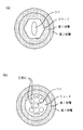
図7に示すファイバデザインの偏光保持動作を可能にするために、非円形の応力生成領域が追加される。例えば、図7aに示すように、非円形(あるいは円形)の応力生成領域が図6aからのファイバ断面に追加される。5角形ファイバと一緒の円形応力生成領域は別々に示されない。そのようなファイバは、シングルモードあるいはマルチモードコアをもつことができる。円形の応力生成領域は7角形ファイバと共に図7bに示されている。一般に、円形の応力生成は、任意の2重クラッドあるいは3重クラッドファイバに合体され、ここで、1番目の内側及び/あるいは2番目の内側クラッドの両者は、非均一である。図7cは偏光保持ファイバの別の実施であり、径的に対称で非等辺の6角形を合体させている。図6と図7における本発明の形態の各々で、ファイバコアは、マルチモードあるいはシングルモードでよい。
【0050】
表1に挙げられたファイバは、受動モードロックYbファイバレーザの共振器の一部としても試験された。本発明のモードロックシステムの一般化された図解が図8に示されている。ファイバは、クラッドに結合された高パワーポンプレーザからの空間的にインコヒーレントな光で側方ポンプされた。バンドパスフィルター(F)は、中心波長1040nmで3nmのスペクトルバンド幅をもっていた。偏光子(P)はファイバの偏光軸の一つに調整された。可飽和吸収体は、ヒートシンクに取り付けられた金フィルムの上に堆積された0.64μmの厚さと1040nmのバンドエッジをもつAlInGaAsのフィルムであった。その吸収体のキャリア寿命は、1psのオーダであった。4%反射の垂直に劈開された共振器内ファイバ端は、出力結合ミラーとして役立った。ファイバ長さが2mの場合、レーザは、ファイバのコアサイズに依存する平均パワー10−40mWで、繰り返し≒50MHzのパルスを発生した。発生したパルス幅は典型的に2psであった。
【0051】
しかしながら、低複屈折と相応して長いビート長とをもつファイバだけが安定なモードロックを起こした。その理由は、小さい値の複屈折の場合、第1偏光軸を伝搬する主信号と第2偏光軸を伝搬する任意の2番目の信号は、一緒にロックし、共振器内で発振できる単一結合偏光状態を発生するからである。ファイバの複屈折が高すぎると、主信号と2番目の信号がロックしなくなり、モードロック過程の不安定で時間的に変化する動作をもたらす。単一偏光状態で安定なモードロックパルスを得るためには、外径が>125μmの中複屈折ファイバの使用で可能になるように、小さい複屈折の値に対しては大きな偏光消光比が必要とされる。さらに、径が>125μmのファイバの使用は、ファイバをより曲がり難くくし、ファイバの曲がりがある場合偏光モード結合を小さくもする、すなわち、大きな径のファイバは、小さな径のファイバに比べ偏光消光比の低下が小さいコイルを可能にする。偏光モード結合を最適化するために、二つのファイバクラッド及び/あるいは二つ(あるいはそれ以上)の適当に選定された被覆材層も実装される。
【0052】
図8に示す共振器も、横モードを1以上維持するコア径11μm(ファイバ#4)のマルチモードファイバで、安定なパルスを発生した。安定なパルス動作を可能にするためのファイバテーパが、モードフィルタとしてファイバ端近くのファイバに合体された。そのテーパは、個別には示されてない。外径を200μmから100μmにテーパ化することで、コア径は同様に11μmから5.5μmにテーパ化され、シングルモード動作を可能にする。結果として、ファイバ内の基本モードが99%の効率で一般的に励起された。この場合に安定なモードロックを確実にするために、可飽和吸収体の寿命は、ファイバ内の基本モードと次の高次モードの間のシングルパス群遅延より短くなければならなかった。その理由は、次の高次モードが共振器の各端部でファイバの基本モードに小さなパルスを結合させるためである。この小さなパルスは、主パルスに関して遅延した時間を得る。しかしながら、その小さなパルスは、2番目の時間遅延パルスの成長のために注入信号を発生する。別のパスの後で、さらに別の時間遅延パルスが発生される。以下同様に発生される。任意の副次的パルスの成長は防止されるが、副次的パルスが可飽和吸収体に強く吸収されるなら、可飽和吸収体の寿命が基本モードと次の高次モードとの間のシングルパス群遅延より短くなければならない。
【0053】
一般に、共振器内部の疑似反射があると、可飽和吸収体の寿命は、疑似パルス(疑似反射で発生された)と共振器内の主パルスとの間の時間遅延より小さくなければならない。
例えば、共振器内に二つの高複屈折ファイバ区間を組み入れたモードロックファイバレーザが図9に示されている。そのファイバ区間の偏光軸は、当然互いに平行あるいは反平行であると考えられる。偏光軸の小さな避けがたい調整ミスにより、”間違った”偏光軸を伝搬する小さなパルスがファイバ区間の間の各接続部で発生される。したがってパルスの安定性は、各ファイバ区間での偏光固有モード間のシングルパス群遅延が、発生したパルス幅より大きいことを必要とする。例えば、ファイバ区間が波長1.55μmで3mmの偏光ビート長と相応する5×10⁻⁴の複屈折をもつとすると、偏光群遅延は2mのファイバ区間で≒3.5psである。長さ2mのファイバ区間の場合、可飽和吸収体は、モードロックレーザの最適な安定化を確実にするために3.5ps以下の寿命をもたなければならなかった。
【0054】
多層被覆ファイバあるいは外径が>125μmのファイバのモード結合の減少度合も、Fermann他の米国特許第6,072,811号に開示されているように、等方的にきつく張力のかかったファイバコイルの偏光保持能の改善を可能にする。そのようなファイバは、微少曲げが誘導するモード結合にもっと少なく感じるので、改善された偏光消光比が得られる。そのようなファイバは、図8の中あるいは高複屈折ファイバの直接の代替として使用される。近似的に等方的な張力コイルファイバを組み入れたモードロックファイバレーザ共振器が図10に示されている。最適なレーザの安定性のためにファイバコイル内で偏光状態が近似的に直線であることを確実にするため、ここで、追加の波長板(w1、w2)が共振器の各端部に組み入れられる。
【0055】
側方ポンプよりむしろ2色ビームスプリッタを通しての端面ポンプモードロック発振器が、図11に示されるように用いられる。利得ファイバは、中複屈折、高複屈折あるいはマルチモードファイバを組み入れることができる。真っ直ぐ劈開したファイバ端は、出力結合の量を減らすために誘電体ミラーでコートされる。あるいは、外部ミラーも出力結合器として使用された。一つあるいは二つのバルク回折格子対、プリズム対あるいはグリズム(grism)対、のような分散補償素子(DC)も、より短いパルスを発生させるためとモードロック動作を簡単にするために共振器内に組み入れられる。さらに、可飽和吸収体ミラー(SA)は標準ミラーで置き換えられ、追加の光変調器が能動型モードロックを通しての短パルスの発生を可能にするために共振器(個々に示されない)内に組み入れられる。光学フィルタ(F)もそのような共振器の一部である。
【0056】
モードロック発振器も、図12に示すように共振器構成部品のさらなる集積化のために利得ファイバに直接描画されたファイバ回折格子を使うことで作られる。また、利得ファイバは、中複屈折、高複屈折、あるいはマルチモード(MM)ファイバを組み入れることができる。回折格子は、必要な出力特性のレーザに応じてチャープあるいはアンチャープされる。ポンプ光が可飽和吸収体のファイバ端から注入されるか、あるいは、側方ポンプの形が用いられるとすると、付加的な信号増幅のための付加的な増幅器ファイバが、共振器のファイバ回折格子端に融着され、その結果、非常にコンパクトな高パワーファイバレーザがもたらされる。そのようなシステム構成は、個別には示されていない。
【0057】
モードロックファイバレーザの一実施形態が図13に示されている。分散補償素子(DC)の組入れは選択性であるが、分散補償素子が負分散を与え、全(正)ファイバ分散の約50%補償するなら最良のシステム性能が得られる。フィルタ(F)は、ファイバの利得バンド幅(FWHM)以下のバンド幅(FWHM)をもつ。NdあるいはYbファイバレーザの場合、最適なフィルタバンド幅は、1−30nmの範囲である。その利得ファイバは、正分散をもつ。そのファイバは、偏光保持型で中複屈折型であり、高複屈折ファイバあるいはMMファイバが用いられる。偏光子はファイバの一つの偏光軸に調節される。放物線型パルスの生成は、高吸収性の可飽和吸収体を使用するときに可能になる。その可飽和吸収体の線形吸収は90%である。可飽和吸収体も深い飽和状態で動作すると、共振器内で高パワーパルスが分解する傾向が抑制される。結果として、線形にチャープした高パワーの放物線型パルスが発生される。放物線型パルスは相対的に自己位相変調に不感であるので、放物線型パルスのエネルギは、ソリトンやガウシアン型パルスに比べ非常に高い。放物線型パルスを得るためのキーパラメータは、発生した出力パルスのスペクトルバンド幅で、これは共振器内のフィルタのバンド幅より大きく、その特徴は、他のモードロック技術では得られない。モードロックYb発振器の場合に得られるパルススペクトルの典型的な例を共振器内のフィルタのバンド幅と比較して図14に示す。共振器内のフィルタのバンド幅に比べて増加したそのスペクトルバンド幅は、理想的な度合いであり、それによって共振器内のパルスは放物線型のパルス形状になる。高パワーの放物線型パルスの発生は示されるようなファブリ−ペロ型共振器に限定されないが、共振器内の正分散増幅導波路や狭いバンドパスフィルタをもつ任意の導波路型レーザ共振器デザインが実施される。パルスのバンド幅が、共振器内のフィルタのバンド幅を越えるときはいつでも、近似的な放物線型パルスの生成が起こる。放物線型パルスの発生の最適な安定性は、吸収体の寿命が発生したパルスの最大幅の5倍より短い時に保証され、発生したパルスの1倍以下の寿命の可飽和吸収体が望ましい。
【0058】
図13に示す放物線型パルス発振器の特定のデザイン例では、共振器内のYbファイバ長が4mで、光学フィルタは10nmのバンド幅をもち、吸収体の非飽和損失が90%で、可飽和吸収体が分散補償素子を有する共振器内の端部に配置された。その可飽和吸収体は4psの寿命をもっていた。分散補償素子は、正のファイバ分散の50%を補償するように調整された。出力結合ミラーは1.05μmの信号波長に対して80%の反射率をもっていた。レーザは、20nJのパルスエネルギに相当する500mW以上の平均パワーをもつパルスを発生した。そのパルスは近似的に線形チャープしており、別の分散補償素子(図示せず)のセットで近似的にバンド幅限界まで再圧縮された。
【0059】
上のシステムは、正分散増幅導波路をもつユニット、部分的な分散補償、光学バンドパスフィルタ及び振幅変調機構を有する正分散体制で動作する図15に示すような一般的な光学システムの一表示である。一般に、部分的な分散補償、すなわちフィルタリング機能と振幅変調機能も導波路素子で与えられる。そのような光学システムは、ファブリ−ペロレーザ共振器、リングレーザ共振器の一部、あるいは電気通信で用いられるような長距離光伝送システムの一部である。
【0060】
偏光保持の中複屈折ファイバは、他のファイバレーザあるいは増幅器の応用にも使用される。そのようなファイバの偏光保持増幅器としての一般的な例が図16に示されている。この例では、信号光が偏光保持ファイバと偏光保持融着を通してPM増幅器に結合される。そのような融着は、融着前に二つのファイバを適切に回転させることで達成される。その増幅器は端面ポンプあるいは側方ポンプされる。ポンプ光は、増幅器ファイバの端部か増幅器ファイバ内のどこかを通して注入される。
【0061】
本発明に対する修正や変更は、前述の開示や教示からその技術に熟練した人には明らかであり、本発明は(後続の)請求項で判断されるということを意図している。
【図面の簡単な説明】
【図1】本発明による大きな径の偏光保持ファイバを図式的に例証している。
【図2】aは本発明によるファイバの典型的な屈折率分布を図解している。
bは別のプリフォーム作製技術で作製されたファイバの屈折率分布を図解している。
【図3】aは出力端ポンピングを用いた本発明によるファイバレーザの構成を図解している。
bは図3aのファイバレーザの利得分布を図解している。
【図4】aは第1クラッドに導入された応力ロッドを持つ本発明による円形コアファイバを図解している。
bは複屈折を最適化するために第1クラッドに空気孔が導入された図4aの代替物を図解している。
【図5】aはソフトな内側被覆とハードな外側被覆を用いる楕円コアファイバの実施形態を図解している。
bは空気孔を有するクラッドで囲まれた円形コアを用いているが,図5aに似ているファイバを図解している。
【図6】aはポリマ被覆の形の外側クラッドで囲まれた5角形の外形線を持つ内側クラッドを備えたファイバを図解している。
bは7角形の外形線とポリマで被覆の形の外側クラッドを持つ内側クラッドを備えたファイバを図解している。
cは、非対称形状の外形線の非等辺6角形、すなわち一辺が短くポリマ被覆の形の外側クラッドを持つ6角形をした内側クラッドを備えたファイバを図解している。
【図7】aは、非円形の応力生成領域とポリマ被覆の形の外側クラッドと合体した5角形の外形線を持つ内側クラッドを備えた偏光保持ファイバを図解している。
bは、円形応力生成領域とポリマ被覆の形の外側クラッドと合体した7角形の外形線をもつ内側クラッドを備えた偏光保持ファイバを図解している。
cは、非対称形状の外形線の非等辺6角形、すなわち円形応力生成領域とポリマ被覆の形の外側クラッドと合体した一辺が短い6角形をした内側クラッドを備えた偏光保持ファイバを図解している。
【図8】マルチモードコアを含むことができる側方ポンプのモードロックファイバ増幅器を図解している。
【図9】共振器内に高複屈折ファイバ区間を有するファイバレーザへの本発明の応用を図解している。
【図10】きつく巻きつけられた近似的に等方性のファイバを有するファイバレーザへの本発明の応用を図解している。
【図11】分散補償を備えた端面ポンプのモードロックファイバレーザを図解している。
【図12】図9に類似の実施形態を図解しており,ここでは、分散補償がファイバ内回折格子である。
【図13】放物線パルスの生成を可能にするために出力のバンド幅が共振器内フィルタのバンド幅より大きいファイバレーザの実施形態を図解している。
【図14】図11のレーザにおけるフィルタの透過スペクトルと出力パルスのスペクトルの比較をしている。
【図15】正分散で動作する導波路型増幅器システムの一般化された描写である。
【図16】偏光保持ファイバレーザシステムの一般的な例を図解している。[0001]
[Industrial application fields]
Field of the invention and overview
The present invention relates to a single polarization optical fiber, i.e., an optical fiber having strong polarization maintaining or polarization maintaining properties, and a fiber laser formed by a modification of the same doped with a rare earth.
[0002]
In accordance with the present invention, an ideal polarization maintaining optical fiber can be made with various alternative technologies. According to one embodiment, the fiber is polarization insensitive to external bending and temperature changes due to increased fiber diameter to minimize polarization mode coupling through a decrease in stress in the fiber core. Alternatively, polarization mode coupling is reduced by special cladding techniques to minimize stress at the fiber-cladding interface. Stress induction techniques are used in the cladding to optimize the birefringence of the fiber.
[0003]
Such rare earth doped multi-clad variants of polarization maintaining fibers are ideal as high power laser light sources and enable effective pumping with high power laser diodes. Fiber lasers can operate in either continuous wave mode or pulsed mode, giving great advantages to fiber laser and amplifier designs whenever polarization stability is paramount. In particular, useful applications of such fibers include high power single frequency fiber amplifiers, high power pulsed fiber amplifiers or mode-locked fiber lasers.
[0004]
The nonlinearity of these devices is minimized while maintaining good polarization maintaining properties by combining the circular inner cladding surrounding the fiber core. The inner cladding defines non-uniform pump absorption along the length of the fiber in an end-face pump amplifier configuration that causes large pump absorption in the first short section of the fiber and reduces pump absorption in the next long section of the fiber. To do. As a result, the gain of the first short fiber section is maximized while the nonlinearity of the fiber is minimized. The effectiveness of non-uniform pump absorption is further maximized by allowing multimode propagation where the central core increases the core diameter and inner cladding diameter, and the capture ratio for pump light coupled to the first inner cladding Increase.
[0005]
The inner core is grown directly through a preform formation process that adds high levels of phosphorus, germanium, or aluminum dopants. A circular inner cladding is formed from the reduced concentration doping region of the preform. The second undoped region of the preform becomes the second outer cladding. A circular inner cladding can also be formed by covering with a suitable tube having a lower refractive index than the inner cladding. The added tube becomes the outer second cladding. In general, the outer shape of this second cladding is non-circular or non-uniform to provide effective absorption throughout the pump light.
[0006]
Effective pump absorption is also achieved by combining the outer coating with a single non-circular cladding. Here, the refractive index of the coating is lower than the refractive index of the cladding. In particular, the non-circular cladding has a contour line having an asymmetric equilateral polygon including, for example, a pentagon or a heptagon. Alternatively, the non-circular cladding has an outline with an asymmetrical non-equal polygon including, for example, a hexagon or an octagon. Such a shape randomizes reflections within the cladding and does not enhance reflections at regular repetition times and distances, but thereby enhances mode mixing within the cladding.
Circular or non-circular stress producing regions within this cladding structure are incorporated into such fibers to achieve polarization maintaining operation.
[0007]
In the case of a mode-locked fiber laser, polarization stable operation is achieved with a fiber with intermediate birefringence, i.e., when the group velocity walk-off between the two polarization axes of the fiber is small compared to the pulse width, Increases sex very much. As a result, particularly small polarization-insensitive passive mode-locked fiber lasers are made by using a saturable absorber in the fiber laser resonator.
[0008]
Polarization stable operation of a mode-locked laser is also achieved with a single polarization fiber resonator with a high birefringence fiber section, where the group velocity walk-off between the two polarization axes in each fiber section is compared to the pulse width. large. In this case, pulse stability is ensured when the main carrier lifetime of the saturable absorber is less than the group velocity walk-off time in each high birefringent fiber section.
[0009]
More generally, if there is a leaky reflection in a passively mode-locked laser resonator, the stability of the pulse is determined by the time delay between the main pulse and the 'leakage' pulse generated by the leaky reflection, and the saturable absorption in the resonator. Guaranteed when longer than the life of the body. In the case of a passively mode-locked multimode fiber laser, pulse stability is achieved when the group velocity walk-off time between the fundamental mode and the next higher order mode is longer than the lifetime of the intracavity saturable absorber.
[0010]
Even more generally, high power operation of a passively mode-locked fiber laser with a chirped pulse is achieved by using a saturable absorber and an intracavity filter that have a lifetime at least comparable to the intracavity pulse width. . The chirp pulse has a reduced peak power and an extended time width. At the output of the fiber laser, the pulses are recompressed in time to a bandwidth limit with a greatly increased peak power and a greatly reduced time width. Laser stability requires that the dispersion of the intracavity fiber is positive, and the intracavity filter must have a bandwidth that is less than the bandwidth of the gain medium. The main lifetime of the saturable absorber needs to be shorter than about 5 times the maximum intracavity pulse width, and the saturable absorber needs to operate at more than twice the saturation (impacts the saturable absorber). The pulse energy must be at least twice as high as the saturation energy of the saturable absorber). The stable oscillation of a chirped recompressible pulse in such a laser is easily characterized by a large intracavity self-phase modulation value exceeding π. As a result, the optical bandwidth of the generated pulse exceeds the bandwidth of the intracavity filter. Therefore, the intracavity pulse shape cannot be approximated by a soliton or Gaussian type, but rather resembles a pulse with a greatly reduced pulse wing compared to a parabolic or Gaussian pulse. This resonator design is compatible with a medium birefringence low polarization mode coupled fiber design, and the use of a multimode fiber increases the output power.
[0011]
[Prior art]
Background of the invention
The development of advanced optical technology in recent years has greatly encouraged the use of fiber lasers as a common alternative to conventional solid state lasers. Compared to solid-state lasers, fiber lasers offer a special potential for integration and miniaturization without compromising performance, and use complex laser processing capabilities for real-world applications that were not previously accessible to solid-state lasers Make it possible.
One of the most important aspects of these advances is the use of a double-clad fiber amplifier design, which allows the fiber laser to be pumped with a wide range of power expandable diode lasers, and the output power is A fiber laser with a continuous wave operation up to 100 W is provided (V. Dominic et al. '110 W Fiber Laser', Conf. On Lasers and Electro-Optics, CLEO, 1999, paper, CPD11).
[0012]
However, these high output powers differ significantly from solid state lasers to date and have only been obtained with randomly polarized output beams. For solid-state lasers, the generation of an output beam with a well-defined polarization state is not a problem. Clearly, there is a need for a fiber laser with a controllable polarization output state for a fiber laser to replace the solid state laser completely, or in particular a double clad fiber laser.
[0013]
So far, several methods have been proposed in which a well-defined polarization state can be generated from a double clad fiber laser. One study disclosed the use of an elliptical fiber core or a high birefringence amplifying fiber by introducing a stress generation region into the fiber cladding (ME Fermann et al. 'Single Mode Amplifier and Compressor', US Patent). 5,818,630, ME Fermann et al. 'Mode-locking technology of multimode fiber and fabrication of small high power fiber laser pulse source', USA 09 / 199,728 filled November 25, 1998, both here Are incorporated as references). The introduction of stress-generating regions into the double clad fiber was later repeated by DiGiovanni in US Pat. No. 5,949,941. However, DiGiovanni describes in the specification the use of a stress generating region in an asymmetric outer cladding. Non-circular stress-generating regions are generally difficult to make and the asymmetric cladding shape hinders the possibility of such fibers to be cleaved and fused to other circular fibers.
[0014]
Recently, a polarization-maintaining fiber amplifier was described by Kliner et al. (D.A.V.Kliner et al. 'Polarization-maintaining amplifier using double-clad butterfly-like fiber' Opt. Lett., Vol. 26, pp. 184 -186 (2001)). Later work by Kliner et al. Discussed the specific implementation of design implied in the '630 patent by Fermann et al. Kliner et al. Uses a fiber with a cladding diameter of 150 μm, where the stress generating region extends to an inner diameter of 20 μm, which means that the stress generating region is very close to the core to maximize fiber birefringence. Is implied. In this study, 1.2 × 10-FourA birefringence as high as (corresponding to a beat length of 8 mm at a wavelength of 1000 nm) was required to achieve a polarization maintaining operation. In addition, only two stress generation regions are incorporated into the cladding, and the double-clad fiber only consists of a circular glass fiber cladding and a circular polymer cladding.
[0015]
However, it is problematic to use a stress generating region as discussed by Kliner et al. This is because the complexity of the fiber preform is increased and a stressed preform is likely to fail whenever processing of the preform surface is required. An example of this is a rectangular cladding (Snitzer et al. 'Optical fiber laser and amplifier' used in US Pat. No. 4,815,079) used to maximize absorption. However, the stress generating region has the beneficial effect of mixing the modes propagating through the cladding, resulting in increased pump absorption.
[0016]
Next, a mode that propagates through the cladding will be referred to as a pump mode. In order to maximize pump mode modal mixing and optimize pump absorption, the stress generation region proximate to the outer diameter of the fiber is optimized. On the other hand, the stress generating region away from the fiber core generates smaller birefringence and reduces the polarization maintaining ability of the fiber. In general, the requirements for optimal pump mode mixing and optimal polarization maintenance are different, and no technique has been described that achieves good polarization maintenance in the presence of optimal pump mode mixing.
[0017]
Similarly, the use of an elliptical core generally does not always produce sufficient birefringence to maintain a stable polarization state. Furthermore, the amount of birefringence induced by the use of an elliptical fiber core decreases with increasing fundamental mode size, where large fundamental mode sizes are suitable for high power applications.
[0018]
In another proposal, asymmetric air holes (A. Ortigossa et al. 'Highly Birefringent Photonic Crystal Fiber', Opt. Lett., 25, 1325-1327 (2000)) have been used to obtain a polarization maintaining effect. . However, such a design was only used for an outer fiber diameter of 63 μm. Therefore, in order to achieve polarization stable operation, a polarization beat length of less than 1 mm was required at a wavelength of 1.54 μm. There is no mention of optimizing the outer fiber diameter or fiber coating, or the use of such fibers as polarization maintaining fiber amplifiers.
[0019]
As another approach to generate a polarization stable output, the use of a fiber wrapped around a small drum has been proposed (ME. Fermann et al. 'Integrated Passive Mode-Locked Fiber Laser and its Fabrication', US Pat. No. 6,072). , 811, Koplow et al. 'Polarization-maintaining double clad fiber amplifier using externally supplied stress-induced birefringence', Opt. Lett., Vol. 25, pp. 387 (2000)). However, tight coils are problematic because they reduce the lifetime of the fiber. Due to lifetime issues, controlled bending is limited to small outer diameter (≈ <200 μm) fibers. Obviously, tightly wound fibers do not allow the fiber delivery of signals via long fiber leads. Furthermore, in order to truly generate a high power fiber laser, the use of a larger diameter fiber is clearly advantageous because more power from the semiconductor laser can be coupled into the fiber.
[0020]
In order to simplify mode control within the fiber core and to reduce mode coupling within the core of the optical fiber, the use of large outer diameter fibers has been proposed (ME Fermann and D. Harter 'single mode amplifier and compressor based on multimode optical fiber' (US Pat. No. 5,818,630). The limitation of this approach is that typical fiber laser and amplifier thresholds are directly proportional to pump intensity. Thus, a larger outer fiber diameter causes a higher threshold and less efficient operation of the fiber amplifier or laser being discussed.
[0021]
Another proposed method for reducing mode coupling within the fiber core is to use two types of coatings. The initial coating surrounding the glass surface of the fiber was proposed to be a soft coating with a correspondingly reduced Young's modulus and a small Poisson's ratio. The second hard coating is proposed to protect the fiber from the outside, the second coating has an increased Young's modulus and a large Poisson's ratio (ST Shiue 'minimizes long-term hydrostatic pressure induced microbending losses Design of a double-coated optical fiber to achieve the above ', Opt. Lett., 26, 128-130 (2001)). However, rare earth doping of such fibers is not considered, and furthermore, no coating design is given to optimize the polarization maintaining ability of the fiber.
[0022]
In general, none of the previous methods imply a way to minimize the amount of polarization mode coupling in a birefringent fiber. The only technology to date that can reduce the amount of polarization mode coupling in birefringent fibers is maximization of fiber birefringence. In contrast, to reduce the amount of polarization mode coupling and polarization mode dispersion, and to increase the optical fiber's polarization holding capacity with small birefringence values, we use the use of large fiber diameters or optimal fiber coatings here. Disclose. In addition, we add the outer glass cladding to the smaller inner circular cladding so that the large outer cladding guides the pump light through the inner cladding while ensuring reduced mode coupling in the fiber core. An improved polarization maintaining large outer diameter fiber amplifier or laser efficiency is disclosed. Similar improvements in the efficiency of polarization maintaining optical fibers are achieved by using a relatively small fiber cladding diameter with an optimized fiber coating.
[0023]
In order to minimize the nonlinearity of high power fiber amplifiers, the use of multimode fiber amplifiers has been proposed (US Pat. No. 5,818,630 and ME Fermann et al., US Pat. No. 5,880, 877). Both of these patents disclose the use of polarization maintaining fibers and double clad fibers. Reference here to '877 also discloses the use of an inner cladding surrounding the fiber core. However, these patents do not disclose how to control the cladding shape to minimize the nonlinearity of high power fiber amplifiers.
[0024]
The cladding shape is generally optimized to create a uniform pump absorption along the length of the fiber (Snitzer et al., US Pat. No. 4,815,079, Martin H, Muendel et al., US Pat. 533, 163, DJ DiGiovanni et al., US Pat. No. 5,966,491, and S. Grubb et al., US Pat. No. 6,157,763). Snitzer et al. Disclose a rectangular cladding with a single mode core, Muendel et al. Disclose a planar polygon for the cladding shape, and Grubb et al. Disclose two verticals outside the inner fiber cladding. The surface provides uniform pump absorption. D. J. et al. In DiGiovanni et al., The triple cladding provides uniform pump absorption, where the first cladding is asymmetrical, the second cladding is circular, and the third cladding is a polymer coating. . In addition, DiGiovanni has also proposed using a non-circular stress generating region for the initial cladding.
[0025]
All of these patents are symmetrical clad shapes such as pentagons, heptagons or distorted hexagons to optimize pump absorption in the clad or to allow such fibers to be fused straight. The use of is not disclosed. Further, DiGiovanni does not disclose the use of a circular stress generating region in the cladding.
Furthermore, none of these reference patents disclose a circular inner cladding to provide non-uniform pump absorption. Similarly, none of these patents disclose a multimode core with a circular inner cladding to provide non-uniform pump absorption.
[0026]
In the field of mode-locked fiber lasers, several techniques have been disclosed for stable operation in the section of a high birefringence fiber. In one approach, the introduction of polarization dependent loss has been proposed to ensure that it operates along one polarization axis (ME Fermann et al., US Pat. No. 5,627,848; See also H. Lin et al., US Pat. No. 6,097,741 as a similar technique, together with Fermann et al., US Pat. The first '848 patent discloses the use of wavelength tuning elements such as filters or bulk diffraction gratings. However, no fiber design that can stably operate a mode-locked laser having a fiber section of a medium birefringence fiber is disclosed. The Fermann '811 patent discloses that stable mode-locking requires a high birefringent fiber section with a polarization beat length of <4 mm at a wavelength of 1.55 μm. In the example discussed there, a beat length of <4 mm at a wavelength of 1.55 μm was used to obtain a polarization stable operation. Furthermore, none of the above three patents describes a specific saturable absorber that achieves pulse stability in a fiber laser with several sections of highly birefringent fiber.
[0027]
Several techniques have also been proposed to increase the available output power in mode-locked fiber lasers. In connection with (unfavorable) highly polarization-sensitive resonators, the use of fibers with different values of dispersion has been described (Tamura, et al. 'Extended pulsed fiber laser, US Pat. No. 5,513,194). Another technique has implied the use of high chirped fiber gratings to operate systems with large values of negative (soliton-supported) dispersion (ME Fermann, et al. 'Oscillating pulses in mode-locked lasers. (Technique for generating high-power optical pulse by dispersion control of width ', see US Pat. No. 5,450,427). The disadvantage of using high chirped fiber gratings is that the generated pulse length increases in proportion to the square root of the total induced negative dispersion, which clearly does not help with the short pulses that can be achieved.
[0028]
Finally, another method requires the use of multimode fiber due to the increase in fundamental mode size and possible output oscillation power (ME Fermann, USA 09/199, 728, filled November). 25, 1998). However, the use of non-uniform pump absorption was not implied in this regard. Furthermore, no specific saturable absorber design for optimizing the stability of such a laser was disclosed, and no specific satisfiable absorber design for optimizing the stability of the laser without a polarization compensator. The fiber design was not disclosed.
[0029]
In addition, all mode-locking techniques that have been demonstrated to date (eg, Fermnn et al. 6,072,811; Lin et al. 6,097,741; Tamura et al. 5,513,194; Fermann et al. 5,450,427; Fermann et al. USAN09 / 199,728) is limited so that the maximum value of self-phase modulation in the resonator is only about π. A small amount of acceptable self-phase modulation is clearly a limiting factor because the amount of self-phase modulation in the laser cavity is directly proportional to the peak power of the generated optical pulse. Another feature of such laser systems is that, due to the small amount of self-phase modulation, the oscillation spectral pulse width is smaller than the bandwidth of any intracavity filter (Tamura et al., 'Filtering with soliton fiber lasers. Optimized 'IEEE Photonics Techn. Lett., 6, 1433-1435, (1994)). When a large amount of self-phase modulation is present, the optical pulse bandwidth is greater than the bandwidth limit of any intracavity optical element, and no specific saturable absorber design is disclosed that allows laser operation. It was.
[0030]
Outside the field of mode-locked lasers, the use of parabolic pulses has been proposed to increase the output power that can be extracted from fiber amplifiers (ME Fermann et al., 'Modular, tunable, high energy super Short pulse fiber light source 'USAN09 / 576, 772, filled May 23, 2000). However, the use of parabolic pulses in fiber resonators has not been disclosed, and further, no effective use of parabolic pulses for optimizing the output power of mode-locked fiber resonators has been disclosed to date. In addition, parabolic pulses allow the fabrication of mode-locked fiber lasers with intra-cavity self-phase modulation values> π, so that the bandwidth of the optical output pulse can be reduced to any intra-cavity bandwidth-limited optical element. It was not disclosed that it would be greater than the bandwidth limit.
[0031]
[Problems to be solved by the invention]
It is an object of the present invention to provide a single-polarization high-power fiber laser and an amplifier that solve the above-mentioned problems of the prior art.
[0032]
[Means for Solving the Problems]
Summary of the Invention
The present invention relates to an ideal polarization maintaining optical fiber. In this fiber, polarization mode coupling and polarization mode dispersion are limited by several techniques, particularly with a decrease in fiber core stress with increasing fiber diameter. As a result, many smaller dimensions of mode coupling and mode dispersion are achieved compared to small diameter fibers. In general, a stress generating region is introduced to optimize polarization maintaining behavior in such a fiber. These stress generation regions have a circular shape.
[0033]
By doping such fibers with rare earths, high power and good polarization fiber lasers and amplifiers can be made without polarization compensation elements. The laser or amplifier threshold and efficiency of such a fiber laser is optimized by using a small inner cladding diameter with at least one 'soft' and one 'hard' coating layer, where the initial coating is' The 'soft' and second 'hard' coating has an enlarged diameter.
[0034]
The laser or amplifier threshold is also minimized by using a non-circular, non-planar symmetrical cladding shape such as a pentagon, heptagon, or distorted hexagon.
Either continuous wave, pulse, or mode-locked operation of such fiber lasers and amplifiers is possible. Such fiber laser nonlinearity is minimized by providing non-uniform pump absorption by adding a small circular inner cladding surrounding the fiber core. Reduced absorption of helical rays in such cladding structures results in reduced pump absorption along the length of the fiber. As a result, large gains are only generated with short-section fibers with high pump absorption. The overall efficiency of the device is guaranteed by limiting the size of the inner cladding with respect to the fiber core size. A large amount of pump light is coupled to the inner cladding when a multimode core is used.
[0035]
When the fiber laser operates in mode-locked mode, polarization stable operation is achieved with a medium birefringent fiber. In this case, it is guaranteed that the polarization walk-off between the two polarization eigenmodes of the fiber is small compared to the generated pulse width. For fibers of any diameter, polarization stable mode-locking is possible with a fiber resonator with a high birefringence fiber section. Passive mode locking is made possible by introducing a saturable absorber in the resonator. Mode-locked stability is ensured when the lifetime of the saturable absorber is less than the single-pass group delay between polarization eigenmodes in each fiber section.
[0036]
More generally, when there is a leaky reflection in a passively mode-locked laser resonator, the stability of the pulse is determined by the time delay between the main pulse and the 'leakage' pulse generated by the leaky reflection, and the saturable absorption in the resonator. Guaranteed when longer than the life of the body. In particular, stable passive mode-locked multimode fiber lasers are made when the lifetime of the saturable absorber is shorter than the single-pass group delay between the first mode and the next higher order mode in the fiber.
[0037]
Alternatively, high power fiber lasers are made using positive dispersion rare earth doped amplifier fibers and narrow bandpass filters as well as saturable absorbers that absorb strongly. Under this condition, the generated pulse in the resonator that closely approaches the parabola (hereinafter referred to as a parabolic pulse) is stable, allowing a large increase in self-phase modulation in the resonator, while it is Gaussian or sech.2The power can be increased compared to a resonator based on a type pulse. Such a resonator design is compatible with the design of medium birefringence low polarization mode coupled fiber and multimode fiber for further increase of output power. Generation of high energy parabolic pulses in a fiber laser resonator is generally characterized by a bandwidth of the optical pulse that is greater than the bandwidth of the intracavity gain medium or the intracavity filter bandwidth. Furthermore, the stability of high energy parabolic pulses within the resonator is ensured when the lifetime of the saturable absorber is less than about 5 times the maximum pulse width within the resonator. The stability of the resonator is further enhanced by operating the saturable absorber in deep saturation, i.e. irradiating the absorber with pulse energy at least twice the saturation energy. The optimum position of the saturable absorber is after the intra-resonator filter, and both these elements are located at the output of the resonator. The addition of partial dispersion compensation by the dispersive element in the resonator further increases the stability of the pulse. These dispersive elements are ideally placed in front of the saturable absorber. The linear loss of the saturable absorber is further increased by optical heating of the saturable absorber using light absorption of light irradiation to the absorber.
[0038]
DETAILED DESCRIPTION OF THE INVENTION
Detailed Description of the Preferred Embodiment
A schematic diagram of a polarization maintaining and large diameter fiber is shown in FIG. The fiber core is elliptical to determine the polarization axis of the fiber. The fiber has a circular (or non-uniform) inner first cladding and a non-uniform (or circular) outer second cladding. Here, the parentheses indicate that the positions of circular and non-uniform cladding can be interchanged. The refractive index of the second cladding is lower than the refractive index of the first cladding. In principle, any cladding shape can be used for a non-uniform cladding, whether the non-uniform cladding is the first cladding or the second cladding. Any glass composition with an appropriate refractive index difference can be used, but the first cladding is made of germanium-doped silica and the second cladding is made of fluorinated glass to obtain the maximum refractive index difference.
[0039]
The fiber is made starting from a circular preform, at which time the preform is processed into an ellipse on both sides. By heating and some additional stretching, the surface tension is utilized to return the preform to a circular shape, forming a circular inner cladding. As a result, the fiber core is elliptical and the inner cladding is circular. The second cladding is made by placing a substrate tube of a suitable second cladding material (fluorinated or borosilicate) over a circular preform and then fusing the tube to the original fiber preform. The second clad is processed to make the outer side of the second clad an arbitrary shape. A third cladding having a low refractive index is made by coating the second cladding with a suitable polymer material. The refractive index profile of such a fiber is shown in FIG.
[0040]
Alternatively, the first cladding is deposited directly around the fiber core heavily doped with germanium, aluminum or phosphosilicate during fabrication of the preform. This first cladding is made with a lower doping level than the core. The numerical aperture of the cladding should be large (greater than 0.15) to allow coupling of large amounts of pump light and can have a circular or elliptical (not shown) cross section. The outer cladding is made by suitable processing of the preform substrate material and then coated as described above. The refractive index profile of such a fiber is shown in FIG.
[0041]
The center or fiber core of the fiber shown in FIG. 1 is doped with any rare earth doped material to allow the fiber to be used as a polarization maintaining amplifier. In this case, a fiber design with a circular inner cladding, as discussed above, is non-uniform along the length of the fiber when end-face pumping from the output end of the fiber amplifier is performed, as shown in FIG. 3a. Guarantee absorption coefficient. Here, the signal light is injected from the left side, and the pump light is injected from the output end of the right fiber amplifier. Due to the reduced absorption of the helical rays within the inner cladding, the effective absorption coefficient of the pump light decreases along the fiber. As a result, the effective signal gain per unit length increases greatly towards the amplifier output, creating a structure with a large gain only in the amplifier output end section as illustrated in FIG. 3b. The peak power achievable with a length L fiber amplifier is generally Leff= [1−exp (−gL)] / g (in the case of constant gain g), the large gain at the output of the amplifier is inversely proportional to the effective amplifier length given by Enables generation of optical signals with peak power. The non-uniform second cladding provides effective absorption for light rays propagating through the second cladding as well as scattering between the first and second cladding interfaces.
[0042]
The second fiber cladding can be removed, but the fiber should then have an outer diameter of> 150 μm to minimize polarization mode coupling within the fiber. The outside of the fiber can have any shape. As shown in FIGS. 4a and 4b, in order to obtain an optimum degree of birefringence, an optional stress generating region (FIG. 4a) or an optional fiber hole (FIG. 4b) is introduced into the fiber cladding. The stress generating regions (or air holes) in the inner cladding can have different shapes as shown in FIG. 4b. Without a stress generating region or air holes, the fiber core major / minor axis ratio must be greater than 1.1. If there is a stress generating region, a circular fiber core can be used. Whether or not any of the second cladding is included, the total outer diameter of the fiber must be greater than 150 μm and the fiber birefringence is 1 × 10⁻⁶Must be bigger. The outside of the fiber is surrounded by a polymer coating for fiber protection. In order to further increase the polarization maintaining ability of the fiber, a soft inner coating and a hard outer coating are used on the outer side of the fiber. A possible choice of such a dressing is the use of a silicone inner coating and an acrylic outer coating. In this case, any fiber diameter can be used and the second cladding can be removed. Two examples of such polarization maintaining fibers are shown in FIG. 5, where FIG. 5a has an elliptical core and FIG. 5b has a circular core surrounded by slightly asymmetric air holes. Yes. The center or fiber core of the fiber shown in FIGS. 4 and 5 is doped with any rare earth doping material to allow the fiber to be used as a polarization maintaining amplifier.
[0043]
A typical polarization maintaining capability of the fiber of the design shown in FIG. 4a is listed in Table 1 below. The fiber has an approximately circular core, and all but fiber 1 has a stress generation region in the cladding. The fiber is 2 m long and wound on a 10 cm diameter reel. The fiber is "double clad" and has a first clad and a low refractive index polymer coating. There is no real second cladding. The fiber was doped with Yb to a doping level of about 2 mol%. The polarization extinction ratio is the amount of light that is coupled to the second polarization axis of the fiber (measured at the fiber output end) when light is coupled to the input end of the first polarization axis of the fiber.
[0044]
Whether comparing fibers 3 and 4, or comparing fibers 5 and 6, the polarization extinction ratio in the fiber can be increased by simply increasing the outer diameter of the fiber for the same polarization beat length. It can be seen that this is improved. Here, the change in the core diameter is proportional to the entire fiber diameter and does not directly affect the polarization holding ability. Since the polarization extinction ratio is a measurement of the polarization holding ability of the fiber, a slight increase in fiber diameter increases the polarization holding ability by an order of magnitude. This advantage persists for any value of fiber birefringence, but a normal fiber with an outer diameter of 125 μm is clearly the most advantageous at intermediate values, and polarization maintaining operation for a given size of birefringence I will not let you. This intermediate value is 1 × 10⁻⁶To 1 × 10-FourIncluding the birefringence value. Here, a fiber having a birefringence in this range is referred to as a medium birefringence fiber. At a wavelength of 1 μm, the corresponding polarization beat length for medium birefringence is between 100 cm and 1.0 cm, respectively.
[0045]
[Table 1]
Effective double-clad fibers can also be made by mounting a fiber with only one inner cladding and an outer cladding in the form of a polymer coating. In this case, the pentagonal inner cladding is mounted as shown in FIG. 6a). Here, the core is in multimode or single mode. Such a cladding shape has a small interior angle that optimizes pump mode coupling and optimizes pump absorption in the fiber. Large pump absorption is clearly beneficial for such fiber applications as high power pulse amplifiers.
A heptagonal cladding shape is possible as shown in FIG. 6b). The heptagon provides less pump mode coupling due to the smaller internal angle between the cladding faces, but because of the close proximity of such a structure to a perfect circle, such fibers are easy to fuse and have many Desirable for application.
[0047]
Remember that these two clads are symmetrical, but do not stretch flat. However, such a cladding allows mode coupling in an intra-fiber pump mode that results in effective absorption of helical light. Due to the resulting uniform pump absorption, such a fiber need not be used to obtain the highest possible power when used as a high peak power pulse amplifier. Instead, 9 or 11 or generally (2n-1) side polygons, where n> 4, are also implemented (not shown).
[0048]
Improved absorption of the helical rays is achieved by using a radially asymmetric and unequal hexagon as shown in FIG. 6c). Such a reduced level of symmetry of the cladding shape results in better pump mode coupling, resulting in maximization of pump mode coupling. Keep in mind that these cladding designs can be modified to incorporate multiple coatings and a second non-circular inner cladding (not shown).
[0049]
A non-circular stress generating region is added to allow polarization maintaining operation of the fiber design shown in FIG. For example, as shown in FIG. 7a, a non-circular (or circular) stress generating region is added to the fiber cross section from FIG. 6a. The circular stress producing region with pentagonal fiber is not shown separately. Such fibers can have single mode or multimode cores. A circular stress generating region is shown in FIG. 7b with a heptagonal fiber. In general, the circular stress generation is merged into any double or triple clad fiber, where both the first inner and / or the second inner cladding are non-uniform. FIG. 7c is another implementation of a polarization-maintaining fiber that combines radially symmetric and unequal hexagons. In each of the embodiments of the invention in FIGS. 6 and 7, the fiber core may be multimode or single mode.
[0050]
The fibers listed in Table 1 were also tested as part of a passive mode-locked Yb fiber laser resonator. A generalized illustration of the mode-locking system of the present invention is shown in FIG. The fiber was laterally pumped with spatially incoherent light from a high power pump laser coupled to the cladding. The bandpass filter (F) had a spectral bandwidth of 3 nm at a center wavelength of 1040 nm. The polarizer (P) was adjusted to one of the polarization axes of the fiber. The saturable absorber was an AlInGaAs film with a thickness of 0.64 μm and a band edge of 1040 nm deposited on a gold film attached to a heat sink. The carrier lifetime of the absorber was on the order of 1 ps. The 4% reflective vertically cleaved intracavity fiber end served as the output coupling mirror. For a fiber length of 2 m, the laser repeatedly generated pulses of ≈50 MHz with an average power of 10-40 mW depending on the fiber core size. The generated pulse width was typically 2 ps.
[0051]
However, only fibers with low birefringence and correspondingly long beat lengths caused stable modelock. The reason is that for small values of birefringence, the main signal propagating on the first polarization axis and the arbitrary second signal propagating on the second polarization axis are locked together and can oscillate in the resonator. This is because a combined polarization state is generated. If the birefringence of the fiber is too high, the main signal and the second signal will not lock, resulting in an unstable and time-varying operation of the mode-locking process. To obtain a stable mode-locked pulse in a single polarization state, a large polarization extinction ratio is required for small birefringence values, as is possible with the use of medium birefringence fibers with an outer diameter> 125 μm. It is said. In addition, the use of a fiber with a diameter> 125 μm makes the fiber more difficult to bend and also reduces the polarization mode coupling if there is a bend in the fiber, i.e. the larger diameter fiber has a lower polarization extinction ratio than the smaller diameter fiber. Enables coils with low drop in In order to optimize polarization mode coupling, two fiber claddings and / or two (or more) appropriately selected coating layers are also implemented.
[0052]
The resonator shown in FIG. 8 is also a multimode fiber having a core diameter of 11 μm (fiber # 4) that maintains one or more transverse modes, and generates stable pulses. A fiber taper to enable stable pulse operation was incorporated into the fiber near the fiber end as a mode filter. The taper is not shown individually. By tapering the outer diameter from 200 μm to 100 μm, the core diameter is similarly tapered from 11 μm to 5.5 μm, enabling single mode operation. As a result, the fundamental mode in the fiber was generally excited with 99% efficiency. In this case, the lifetime of the saturable absorber had to be shorter than the single path group delay between the fundamental mode and the next higher order mode in the fiber to ensure stable mode locking. The reason is that the next higher order mode couples a small pulse to the fundamental mode of the fiber at each end of the resonator. This small pulse gets a delayed time with respect to the main pulse. However, the small pulse generates an injection signal for the growth of the second time delay pulse. After another pass, another time delay pulse is generated. The same applies to the following. The growth of any secondary pulse is prevented, but if the secondary pulse is strongly absorbed by the saturable absorber, the lifetime of the saturable absorber is a single between the fundamental mode and the next higher mode. Must be shorter than the path group delay.
[0053]
In general, if there is a pseudo reflection inside the resonator, the lifetime of the saturable absorber must be less than the time delay between the pseudo pulse (generated by the pseudo reflection) and the main pulse in the resonator.
For example, a mode-locked fiber laser incorporating two high birefringent fiber sections in the resonator is shown in FIG. The polarization axes of the fiber section are naturally considered to be parallel or antiparallel to each other. Due to the small unavoidable misalignment of the polarization axis, small pulses propagating on the “wrong” polarization axis are generated at each connection between the fiber sections. Thus, pulse stability requires that the single-pass group delay between polarization eigenmodes in each fiber section is greater than the generated pulse width. For example, the fiber section is 5 × 10 corresponding to a polarization beat length of 3 mm at a wavelength of 1.55 μm.-FourThe birefringence of the polarization group delay is approximately 3.5 ps in a 2 m fiber section. For a 2 m long fiber section, the saturable absorber had to have a lifetime of 3.5 ps or less to ensure optimal stabilization of the mode-locked laser.
[0054]
The degree of reduction in mode coupling of multi-layer coated fibers or fibers with outer diameters> 125 μm is also known to be isotropically tensioned fiber coils as disclosed in Fermann et al. US Pat. No. 6,072,811. This makes it possible to improve the polarization maintaining ability. Such fibers are less sensitive to mode coupling induced by microbending, resulting in an improved polarization extinction ratio. Such fibers are used as a direct alternative to the middle or high birefringent fibers in FIG. A mode-locked fiber laser resonator incorporating an approximately isotropic tension coil fiber is shown in FIG. Here, additional wave plates (w1, w2) are incorporated at each end of the resonator to ensure that the polarization state is approximately linear in the fiber coil for optimal laser stability. It is done.
[0055]
An end face pump mode-locked oscillator through a dichroic beam splitter rather than a side pump is used as shown in FIG. The gain fiber can incorporate medium birefringence, high birefringence or multimode fiber. The straight-cleaved fiber end is coated with a dielectric mirror to reduce the amount of output coupling. Alternatively, an external mirror was also used as the output coupler. Dispersion compensation elements (DC), such as one or two bulk diffraction grating pairs, prism pairs or grism pairs, are also included in the resonator to generate shorter pulses and to simplify mode-lock operation. Is incorporated into. In addition, the saturable absorber mirror (SA) is replaced with a standard mirror and an additional light modulator is incorporated in the resonator (not shown individually) to allow generation of short pulses through active mode-locking. It is done. The optical filter (F) is also part of such a resonator.
[0056]
A mode-locked oscillator is also created by using a fiber grating drawn directly on the gain fiber for further integration of the resonator components as shown in FIG. The gain fiber can also incorporate medium birefringence, high birefringence, or multimode (MM) fiber. The diffraction grating is chirped or unchirped depending on the laser with the required output characteristics. If the pump light is injected from the fiber end of the saturable absorber, or if a lateral pump shape is used, then an additional amplifier fiber for additional signal amplification is provided in the resonator fiber grating. Fused to the end, resulting in a very compact high power fiber laser. Such a system configuration is not shown individually.
[0057]
One embodiment of a mode-locked fiber laser is shown in FIG. The incorporation of a dispersion compensation element (DC) is selective, but the best system performance is obtained if the dispersion compensation element provides negative dispersion and compensates for about 50% of the total (positive) fiber dispersion. The filter (F) has a bandwidth (FWHM) that is less than or equal to the gain bandwidth (FWHM) of the fiber. For Nd or Yb fiber lasers, the optimum filter bandwidth is in the range of 1-30 nm. The gain fiber has positive dispersion. The fiber is a polarization maintaining type and a medium birefringence type, and a high birefringence fiber or an MM fiber is used. The polarizer is adjusted to one polarization axis of the fiber. Generation of parabolic pulses is possible when using highly absorbing saturable absorbers. The linear absorption of the saturable absorber is 90%. When the saturable absorber also operates in a deep saturated state, the tendency of the high power pulse to decompose in the resonator is suppressed. As a result, a linearly chirped high power parabolic pulse is generated. Since parabolic pulses are relatively insensitive to self-phase modulation, the energy of parabolic pulses is much higher than soliton and Gaussian pulses. The key parameter for obtaining a parabolic pulse is the spectral bandwidth of the generated output pulse, which is larger than the bandwidth of the filter in the resonator, and its characteristics cannot be obtained with other mode-locking techniques. A typical example of a pulse spectrum obtained in the case of a mode-locked Yb oscillator is shown in FIG. 14 in comparison with the filter bandwidth in the resonator. Its spectral bandwidth, which is increased compared to the bandwidth of the filter in the resonator, is an ideal degree, whereby the pulses in the resonator have a parabolic pulse shape. The generation of high power parabolic pulses is not limited to Fabry-Perot resonators as shown, but any waveguide laser resonator design with a positive dispersion amplifier waveguide or narrow bandpass filter in the resonator can be used. To be implemented. Whenever the pulse bandwidth exceeds the filter bandwidth in the resonator, the generation of an approximate parabolic pulse occurs. Optimal stability for the generation of parabolic pulses is guaranteed when the lifetime of the absorber is less than 5 times the maximum width of the generated pulse, and a saturable absorber with a lifetime of less than 1 time of the generated pulse is desirable.
[0058]
In the specific design example of the parabolic pulse oscillator shown in FIG. 13, the Yb fiber length in the resonator is 4 m, the optical filter has a bandwidth of 10 nm, the desaturation loss of the absorber is 90%, and the saturable absorption. The body was placed at the end in a resonator with a dispersion compensation element. The saturable absorber had a lifetime of 4 ps. The dispersion compensation element was adjusted to compensate 50% of the positive fiber dispersion. The output coupling mirror had a reflectivity of 80% for a signal wavelength of 1.05 μm. The laser generated a pulse with an average power of 500 mW or more, corresponding to a pulse energy of 20 nJ. The pulse was approximately linearly chirped and recompressed approximately to the bandwidth limit with another set of dispersion compensation elements (not shown).
[0059]
The above system is a representation of a typical optical system as shown in FIG. 15 that operates in a positive dispersion regime with a unit having a positive dispersion amplification waveguide, partial dispersion compensation, an optical bandpass filter and an amplitude modulation mechanism. It is. In general, partial dispersion compensation, i.e. filtering and amplitude modulation functions, are also provided by the waveguide element. Such optical systems are Fabry-Perot laser resonators, part of ring laser resonators, or part of long-haul optical transmission systems such as those used in telecommunications.
[0060]
Polarization-maintaining medium birefringent fibers are also used in other fiber laser or amplifier applications. A general example of such a fiber as a polarization maintaining amplifier is shown in FIG. In this example, signal light is coupled to the PM amplifier through a polarization maintaining fiber and polarization maintaining fusion. Such fusing is accomplished by appropriately rotating the two fibers prior to fusing. The amplifier is end pumped or side pumped. The pump light is injected through the end of the amplifier fiber or somewhere in the amplifier fiber.
[0061]
Modifications and variations to the present invention will be apparent to those skilled in the art from the foregoing disclosure and teachings, and the present invention is intended to be determined by the (subsequent) claims.
[Brief description of the drawings]
FIG. 1 schematically illustrates a large diameter polarization maintaining fiber according to the present invention.
FIG. 2a illustrates a typical refractive index profile of a fiber according to the present invention.
b illustrates the refractive index profile of a fiber fabricated with another preform fabrication technique.
FIG. 3a illustrates the configuration of a fiber laser according to the present invention using output end pumping.
b illustrates the gain distribution of the fiber laser of FIG. 3a.
FIG. 4a illustrates a circular core fiber according to the invention with a stress rod introduced into the first cladding.
b illustrates the alternative of FIG. 4a in which air holes are introduced into the first cladding to optimize birefringence.
FIG. 5a illustrates an embodiment of an elliptical core fiber using a soft inner coating and a hard outer coating.
b uses a circular core surrounded by a cladding with air holes, but illustrates a fiber similar to FIG. 5a.
FIG. 6a illustrates a fiber with an inner cladding having a pentagonal outline surrounded by an outer cladding in the form of a polymer coating.
b illustrates a fiber with an inner cladding having a heptagonal outline and an outer cladding in the form of a polymer coating.
c illustrates a fiber with an inner cladding having an asymmetrical outer shape non-equilateral hexagon, ie, a hexagon with an outer cladding in the form of a polymer coating that is short on one side.
FIG. 7a illustrates a polarization maintaining fiber with an inner cladding having a pentagonal outline merged with a non-circular stress generating region and an outer cladding in the form of a polymer coating.
b illustrates a polarization maintaining fiber with an inner cladding having a heptagonal outline merged with a circular stress generating region and an outer cladding in the form of a polymer coating.
c illustrates a polarization-maintaining fiber with an asymmetrical outline non-isolateral hexagon, i.e., an inner cladding with a short hexagonal side combined with a circular stress generating region and an outer cladding in the form of a polymer coating. .
FIG. 8 illustrates a side-pump mode-locked fiber amplifier that can include a multimode core.
FIG. 9 illustrates the application of the present invention to a fiber laser having a high birefringence fiber section in the resonator.
FIG. 10 illustrates the application of the present invention to a fiber laser having a tightly wound approximately isotropic fiber.
FIG. 11 illustrates an end-pump mode-locked fiber laser with dispersion compensation.
FIG. 12 illustrates an embodiment similar to FIG. 9, where the dispersion compensation is an in-fiber diffraction grating.
FIG. 13 illustrates an embodiment of a fiber laser in which the output bandwidth is greater than the bandwidth of the intracavity filter to allow generation of parabolic pulses.
FIG. 14 compares the transmission spectrum of the filter and the spectrum of the output pulse in the laser of FIG.
FIG. 15 is a generalized depiction of a waveguide amplifier system operating with positive dispersion.
FIG. 16 illustrates a general example of a polarization maintaining fiber laser system.
Claims (10)
前記ファイバコアを囲む第1クラッドと、
前記第1クラッド内に設けられた応力生成領域と、
前記第1クラッドを囲む被覆と、
を有し、少なくとも前記ファイバコアが希土類ドープ材料でドープされ、前記第1クラッドが、5角形、7角形、非対称非等辺6角形、非対称非等辺8角形、あるいはn>4で(2n−1)の辺をもつ多角形の断面形状をもち、前記ファイバコアにシングルモードの光を伝搬させることを特徴とする偏光保持ファイバ。A multimode fiber core having a birefringence between 1 × 10 −6 and 1 × 10 −4 for the fundamental mode;
A first cladding surrounding the fiber core;
A stress generating region provided in the first cladding;
A coating surrounding the first cladding;
And at least the fiber core is doped with a rare earth doped material, and the first cladding is pentagonal, heptagonal, asymmetrical isosceles hexagonal, asymmetrical isosceles octagonal, or n> 4 (2n-1) A polarization-maintaining fiber characterized by having a polygonal cross-sectional shape with sides of the single-mode light propagating through the fiber core.
Applications Claiming Priority (2)
| Application Number | Priority Date | Filing Date | Title |
|---|---|---|---|
| US09/809248 | 2001-03-16 | ||
| US09/809,248 US6954575B2 (en) | 2001-03-16 | 2001-03-16 | Single-polarization high power fiber lasers and amplifiers |
Related Child Applications (3)
| Application Number | Title | Priority Date | Filing Date |
|---|---|---|---|
| JP2005074104A Division JP4348309B2 (en) | 2001-03-16 | 2005-03-15 | Mode-locked fiber laser |
| JP2008040435A Division JP2008158547A (en) | 2001-03-16 | 2008-02-21 | Polarization maintaining fiber, polarization maintaining fiber laser, passive mode-locking fiber laser, fiber amplifier and optical fiber |
| JP2009142237A Division JP2009205174A (en) | 2001-03-16 | 2009-06-15 | Polarization maintaining fiber, fiber amplifier, and fiber laser |
Publications (2)
| Publication Number | Publication Date |
|---|---|
| JP2002323636A JP2002323636A (en) | 2002-11-08 |
| JP4490619B2 true JP4490619B2 (en) | 2010-06-30 |
Family
ID=25200876
Family Applications (6)
| Application Number | Title | Priority Date | Filing Date |
|---|---|---|---|
| JP2002072975A Expired - Fee Related JP4490619B2 (en) | 2001-03-16 | 2002-03-15 | Polarization-maintaining fiber, fiber laser, and fiber amplifier |
| JP2005074104A Expired - Fee Related JP4348309B2 (en) | 2001-03-16 | 2005-03-15 | Mode-locked fiber laser |
| JP2008040435A Pending JP2008158547A (en) | 2001-03-16 | 2008-02-21 | Polarization maintaining fiber, polarization maintaining fiber laser, passive mode-locking fiber laser, fiber amplifier and optical fiber |
| JP2009096761A Expired - Fee Related JP4994415B2 (en) | 2001-03-16 | 2009-04-13 | Passive mode-locked fiber laser |
| JP2009142237A Pending JP2009205174A (en) | 2001-03-16 | 2009-06-15 | Polarization maintaining fiber, fiber amplifier, and fiber laser |
| JP2012181613A Expired - Fee Related JP5899084B2 (en) | 2001-03-16 | 2012-08-20 | Polarization-maintaining mode-locked fiber laser oscillator |
Family Applications After (5)
| Application Number | Title | Priority Date | Filing Date |
|---|---|---|---|
| JP2005074104A Expired - Fee Related JP4348309B2 (en) | 2001-03-16 | 2005-03-15 | Mode-locked fiber laser |
| JP2008040435A Pending JP2008158547A (en) | 2001-03-16 | 2008-02-21 | Polarization maintaining fiber, polarization maintaining fiber laser, passive mode-locking fiber laser, fiber amplifier and optical fiber |
| JP2009096761A Expired - Fee Related JP4994415B2 (en) | 2001-03-16 | 2009-04-13 | Passive mode-locked fiber laser |
| JP2009142237A Pending JP2009205174A (en) | 2001-03-16 | 2009-06-15 | Polarization maintaining fiber, fiber amplifier, and fiber laser |
| JP2012181613A Expired - Fee Related JP5899084B2 (en) | 2001-03-16 | 2012-08-20 | Polarization-maintaining mode-locked fiber laser oscillator |
Country Status (3)
| Country | Link |
|---|---|
| US (3) | US6954575B2 (en) |
| JP (6) | JP4490619B2 (en) |
| DE (2) | DE10211352A1 (en) |
Families Citing this family (164)
| Publication number | Priority date | Publication date | Assignee | Title |
|---|---|---|---|---|
| WO2005022705A2 (en) * | 1997-03-21 | 2005-03-10 | Imra America, Inc. | High energy optical fiber amplifier for picosecond-nanosecond pulses for advanced material processing applications |
| US7656578B2 (en) | 1997-03-21 | 2010-02-02 | Imra America, Inc. | Microchip-Yb fiber hybrid optical amplifier for micro-machining and marking |
| US7576909B2 (en) * | 1998-07-16 | 2009-08-18 | Imra America, Inc. | Multimode amplifier for amplifying single mode light |
| US6275512B1 (en) | 1998-11-25 | 2001-08-14 | Imra America, Inc. | Mode-locked multimode fiber laser pulse source |
| US7068900B2 (en) * | 1999-12-24 | 2006-06-27 | Croteau Andre | Multi-clad doped optical fiber |
| US6885683B1 (en) | 2000-05-23 | 2005-04-26 | Imra America, Inc. | Modular, high energy, widely-tunable ultrafast fiber source |
| US7190705B2 (en) | 2000-05-23 | 2007-03-13 | Imra America. Inc. | Pulsed laser sources |
| FR2811437A1 (en) * | 2000-07-06 | 2002-01-11 | Cit Alcatel | SHEATH PUMPED OPTICAL FIBER AND METHOD FOR MANUFACTURING SUCH FIBER |
| US7567596B2 (en) | 2001-01-30 | 2009-07-28 | Board Of Trustees Of Michigan State University | Control system and apparatus for use with ultra-fast laser |
| US7973936B2 (en) | 2001-01-30 | 2011-07-05 | Board Of Trustees Of Michigan State University | Control system and apparatus for use with ultra-fast laser |
| US8208505B2 (en) | 2001-01-30 | 2012-06-26 | Board Of Trustees Of Michigan State University | Laser system employing harmonic generation |
| US7450618B2 (en) | 2001-01-30 | 2008-11-11 | Board Of Trustees Operating Michigan State University | Laser system using ultrashort laser pulses |
| US7583710B2 (en) | 2001-01-30 | 2009-09-01 | Board Of Trustees Operating Michigan State University | Laser and environmental monitoring system |
| US6954575B2 (en) | 2001-03-16 | 2005-10-11 | Imra America, Inc. | Single-polarization high power fiber lasers and amplifiers |
| US6816513B2 (en) * | 2001-04-02 | 2004-11-09 | Apollo Instruments, Inc. | High power high efficiency cladding pumping fiber laser |
| US6825974B2 (en) * | 2001-11-06 | 2004-11-30 | Sandia National Laboratories | Linearly polarized fiber amplifier |
| US6707957B1 (en) * | 2001-12-18 | 2004-03-16 | Nortel Networks Limited | Compensating for polarisation mode dispersion in optical transmission fibers |
| US7068896B1 (en) | 2002-02-07 | 2006-06-27 | Northwestern University | Method and system for the controlled production of polarization mode dispersion |
| US7116887B2 (en) * | 2002-03-19 | 2006-10-03 | Nufern | Optical fiber |
| JP2003283016A (en) * | 2002-03-25 | 2003-10-03 | Aisin Seiki Co Ltd | Passive type mode-locked fiber laser |
| US6842570B2 (en) * | 2002-12-11 | 2005-01-11 | Northrop Grumman Corporation | Method for coupling diode array light into an optical fiber |
| US7110647B2 (en) * | 2003-01-17 | 2006-09-19 | Nufern | Multimode polarization maintaining double clad fiber |
| JP4301822B2 (en) * | 2003-01-24 | 2009-07-22 | 富士通株式会社 | Optical amplifier with polarization mode dispersion compensation function |
| WO2004066457A1 (en) | 2003-01-24 | 2004-08-05 | Trumpf, Inc. | Side-pumped fiber laser |
| EP1586144B1 (en) * | 2003-01-24 | 2016-05-11 | Trumpf, Inc. | Fiber laser |
| US6959022B2 (en) * | 2003-01-27 | 2005-10-25 | Ceramoptec Gmbh | Multi-clad optical fiber lasers and their manufacture |
| US7414780B2 (en) | 2003-06-30 | 2008-08-19 | Imra America, Inc. | All-fiber chirped pulse amplification systems |
| US7257302B2 (en) * | 2003-06-03 | 2007-08-14 | Imra America, Inc. | In-line, high energy fiber chirped pulse amplification system |
| US7120340B2 (en) * | 2003-06-19 | 2006-10-10 | Corning Incorporated | Single polarization optical fiber laser and amplifier |
| GB0314817D0 (en) * | 2003-06-25 | 2003-07-30 | Southampton Photonics Ltd | Apparatus for providing optical radiation |
| US7113327B2 (en) * | 2003-06-27 | 2006-09-26 | Imra America, Inc. | High power fiber chirped pulse amplification system utilizing telecom-type components |
| US7280730B2 (en) * | 2004-01-16 | 2007-10-09 | Imra America, Inc. | Large core holey fibers |
| US7724422B2 (en) * | 2004-01-30 | 2010-05-25 | Nufern | Method and apparatus for providing light having a selected polarization with an optical fiber |
| WO2005074573A2 (en) | 2004-01-30 | 2005-08-18 | Nufern | Method and apparatus for providing light having a selected polarization with an optical fiber |
| KR100617713B1 (en) | 2004-02-12 | 2006-08-28 | 삼성전자주식회사 | Method for fabricating holey fiber |
| WO2005082801A2 (en) | 2004-02-20 | 2005-09-09 | Corning Incorporated | Optical fiber and method for making such fiber |
| JP4451696B2 (en) * | 2004-03-30 | 2010-04-14 | 富士通株式会社 | Device for canceling wavelength dependence of nonlinear coefficient of microstructured fiber |
| US7804864B2 (en) | 2004-03-31 | 2010-09-28 | Imra America, Inc. | High power short pulse fiber laser |
| US20050226580A1 (en) * | 2004-04-08 | 2005-10-13 | Samson Bryce N | Optical fiber for handling higher powers |
| US7483610B2 (en) * | 2004-05-03 | 2009-01-27 | Nufern | Optical fiber having reduced defect density |
| US7317857B2 (en) * | 2004-05-03 | 2008-01-08 | Nufem | Optical fiber for delivering optical energy to or from a work object |
| US6970632B2 (en) * | 2004-05-03 | 2005-11-29 | Corning Incorporated | Solid type single polarization fiber and apparatus |
| CA2466970A1 (en) * | 2004-05-12 | 2005-11-12 | Coractive High-Tech Inc. | Double-clad optical fibers |
| DE102004027625A1 (en) | 2004-06-05 | 2006-01-05 | Trumpf Laser Gmbh + Co. Kg | High power fiber laser amplifier and fiber laser oscillator |
| KR100678889B1 (en) * | 2004-08-05 | 2007-02-07 | 삼성전자주식회사 | Electric program guide providing device and method for video on demand service |
| WO2006017802A2 (en) * | 2004-08-05 | 2006-02-16 | Nufern | Fiber optic article |
| US7062137B2 (en) * | 2004-08-05 | 2006-06-13 | Nufern | Fiber optic article including fluorine |
| US7050686B2 (en) * | 2004-08-05 | 2006-05-23 | Nufern | Fiber optic article with inner region |
| US7924892B2 (en) * | 2004-08-25 | 2011-04-12 | Kla-Tencor Technologies Corporation | Fiber amplifier based light source for semiconductor inspection |
| US7203407B2 (en) * | 2004-10-21 | 2007-04-10 | Corning Incorporated | Rare earth doped single polarization double clad optical fiber and a method for making such fiber |
| US7280728B2 (en) * | 2004-10-22 | 2007-10-09 | Corning Incorporated | Rare earth doped single polarization double clad optical fiber with plurality of air holes |
| US7508853B2 (en) | 2004-12-07 | 2009-03-24 | Imra, America, Inc. | Yb: and Nd: mode-locked oscillators and fiber systems incorporated in solid-state short pulse laser systems |
| US20060139727A1 (en) * | 2004-12-28 | 2006-06-29 | Rachid Gafsi | Hybrid fiber polarization dependent isolator, and laser module incorporating the same |
| US7209619B2 (en) * | 2004-12-30 | 2007-04-24 | Imra America, Inc. | Photonic bandgap fibers |
| FR2881845B1 (en) * | 2005-02-04 | 2007-06-01 | Centre Nat Rech Scient | COMPOSITE OPTICAL FIBER FOR PUMP AND LASER WAVE CONTAINING LASER, LASER APPLICATIONS |
| US8633437B2 (en) | 2005-02-14 | 2014-01-21 | Board Of Trustees Of Michigan State University | Ultra-fast laser system |
| US7787729B2 (en) * | 2005-05-20 | 2010-08-31 | Imra America, Inc. | Single mode propagation in fibers and rods with large leakage channels |
| GB2427910B (en) * | 2005-07-02 | 2008-03-12 | Sensor Highway Ltd | Fiber optic temperature and pressure sensor and system incorporating same |
| US7391561B2 (en) * | 2005-07-29 | 2008-06-24 | Aculight Corporation | Fiber- or rod-based optical source featuring a large-core, rare-earth-doped photonic-crystal device for generation of high-power pulsed radiation and method |
| DE102005042073B4 (en) * | 2005-08-31 | 2010-11-11 | Fraunhofer-Gesellschaft zur Förderung der angewandten Forschung e.V. | fiber laser |
| US7778290B2 (en) * | 2005-10-02 | 2010-08-17 | Elbit Systems Electro-Optics Elop Ltd. | Fiber lasers |
| US7809222B2 (en) * | 2005-10-17 | 2010-10-05 | Imra America, Inc. | Laser based frequency standards and their applications |
| US8618470B2 (en) | 2005-11-30 | 2013-12-31 | Board Of Trustees Of Michigan State University | Laser based identification of molecular characteristics |
| US7570856B1 (en) * | 2005-12-07 | 2009-08-04 | Lockheed Martin Corporation | Apparatus and method for an erbium-doped fiber for high peak-power applications |
| GB2434483A (en) * | 2006-01-20 | 2007-07-25 | Fianium Ltd | High-Power Short Optical Pulse Source |
| US7382957B2 (en) * | 2006-01-30 | 2008-06-03 | Corning Incorporated | Rare earth doped double clad optical fiber with plurality of air holes and stress rods |
| US8120778B2 (en) | 2009-03-06 | 2012-02-21 | Imra America, Inc. | Optical scanning and imaging systems based on dual pulsed laser systems |
| US8571075B2 (en) | 2010-11-29 | 2013-10-29 | Imra America, Inc. | Frequency comb source with large comb spacing |
| JP2007273600A (en) * | 2006-03-30 | 2007-10-18 | Furukawa Electric Co Ltd:The | Optical fiber laser |
| WO2007145702A2 (en) | 2006-04-10 | 2007-12-21 | Board Of Trustees Of Michigan State University | Laser material processing systems and methods with, in particular, use of a hollow waveguide for broadening the bandwidth of the pulse above 20 nm |
| US7658514B2 (en) * | 2006-04-13 | 2010-02-09 | Lg Electronics Inc. | Light guide, method and apparatus for manufacturing the same, and illuminating system having the same |
| CA2652006C (en) | 2006-05-11 | 2017-05-30 | Spi Lasers Uk Limited | Apparatus for providing optical radiation |
| US7768700B1 (en) | 2006-11-30 | 2010-08-03 | Lockheed Martin Corporation | Method and apparatus for optical gain fiber having segments of differing core sizes |
| US20070280304A1 (en) * | 2006-06-05 | 2007-12-06 | Jochen Deile | Hollow Core Fiber Laser |
| GB2444091A (en) * | 2006-11-24 | 2008-05-28 | Gsi Group Ltd | A Laser Amplifier |
| FR2903817B1 (en) * | 2006-07-13 | 2010-06-25 | Femlight | FIBER OPTIC POWER LASER DEVICE |
| US7289263B1 (en) | 2006-08-02 | 2007-10-30 | Coherent, Inc. | Double-pass fiber amplifier |
| GB0623835D0 (en) * | 2006-11-29 | 2007-01-10 | Cascade Technologies Ltd | Multi mode fibre perturber |
| FR2909776B1 (en) * | 2006-12-12 | 2009-06-05 | Centre Nat Rech Scient | DOPED OPTICAL FIBER WITH BROKEN SPACE SYMMETRY |
| US7437046B2 (en) * | 2007-02-12 | 2008-10-14 | Furukawa Electric North America, Inc. | Optical fiber configuration for dissipating stray light |
| US7496260B2 (en) * | 2007-03-27 | 2009-02-24 | Imra America, Inc. | Ultra high numerical aperture optical fibers |
| EP2179312A1 (en) * | 2007-07-20 | 2010-04-28 | Corning Incorporated | Large-mode-area optical fiber |
| US7876495B1 (en) | 2007-07-31 | 2011-01-25 | Lockheed Martin Corporation | Apparatus and method for compensating for and using mode-profile distortions caused by bending optical fibers |
| US7924500B1 (en) * | 2007-07-21 | 2011-04-12 | Lockheed Martin Corporation | Micro-structured fiber profiles for mitigation of bend-loss and/or mode distortion in LMA fiber amplifiers, including dual-core embodiments |
| US7983312B2 (en) | 2007-08-09 | 2011-07-19 | Raytheon Company | Method and apparatus for generation and amplification of light in a semi-guiding high aspect ratio core fiber |
| JPWO2009028614A1 (en) * | 2007-08-28 | 2010-12-02 | 株式会社フジクラ | Rare earth doped core multi-clad fiber, fiber amplifier and fiber laser |
| WO2009042347A1 (en) | 2007-09-26 | 2009-04-02 | Imra America, Inc. | Glass large-core optical fibers |
| US7593435B2 (en) * | 2007-10-09 | 2009-09-22 | Ipg Photonics Corporation | Powerful fiber laser system |
| US8311069B2 (en) | 2007-12-21 | 2012-11-13 | Board Of Trustees Of Michigan State University | Direct ultrashort laser system |
| US7991022B1 (en) * | 2008-01-16 | 2011-08-02 | Calmar Optcom, Inc. | Optical pulse amplification based on stimulated Raman scattering |
| US8731358B2 (en) * | 2008-01-17 | 2014-05-20 | Claude Pare | Multi-cladding fiber |
| US8213077B2 (en) * | 2008-04-22 | 2012-07-03 | Imra America, Inc. | Multi-clad optical fibers |
| US9063289B1 (en) | 2008-06-30 | 2015-06-23 | Nlight Photonics Corporation | Multimode fiber combiners |
| US9857536B2 (en) * | 2008-07-14 | 2018-01-02 | Chiral Photonics, Inc. | Optical component assembly for use with an optical device |
| US20170191314A1 (en) * | 2008-08-20 | 2017-07-06 | Foro Energy, Inc. | Methods and Systems for the Application and Use of High Power Laser Energy |
| CA2734492C (en) * | 2008-08-20 | 2016-05-17 | Foro Energy Inc. | Method and system for advancement of a borehole using a high power laser |
| US9285541B2 (en) | 2008-08-21 | 2016-03-15 | Nlight Photonics Corporation | UV-green converting fiber laser using active tapers |
| US9158070B2 (en) * | 2008-08-21 | 2015-10-13 | Nlight Photonics Corporation | Active tapers with reduced nonlinearity |
| DK2451031T3 (en) * | 2008-11-17 | 2019-07-29 | Raytheon Co | Method and apparatus for generating and amplifying light in a semiconducting high aspect ratio fiber |
| US8675699B2 (en) | 2009-01-23 | 2014-03-18 | Board Of Trustees Of Michigan State University | Laser pulse synthesis system |
| JP2010177469A (en) * | 2009-01-29 | 2010-08-12 | Furukawa Electric Co Ltd:The | Optical fiber laser and optical fiber amplifier |
| WO2010141128A2 (en) | 2009-03-05 | 2010-12-09 | Board Of Trustees Of Michigan State University | Laser amplification system |
| JP2010258120A (en) * | 2009-04-23 | 2010-11-11 | Fujifilm Corp | Ultrashort pulse light source, and two-photon absorption recording medium recording apparatus having the same |
| US9494738B1 (en) | 2009-05-28 | 2016-11-15 | Nlight, Inc. | Single mode fiber combiners |
| WO2011041472A1 (en) | 2009-10-02 | 2011-04-07 | Imra America, Inc. | Optical signal processing with modelocked lasers |
| WO2011060817A1 (en) * | 2009-11-19 | 2011-05-26 | Vrije Universiteit Brussel | Optical fiber structure for sensors |
| US8503840B2 (en) * | 2010-08-23 | 2013-08-06 | Lockheed Martin Corporation | Optical-fiber array method and apparatus |
| EP2526592B1 (en) * | 2010-01-22 | 2021-06-23 | Newport Corporation | Broadly tunable optical parametric oscillator |
| JP2011171619A (en) * | 2010-02-22 | 2011-09-01 | Fujikura Ltd | Optical fiber for amplification and optical fiber amplifier using the same |
| US8630322B2 (en) | 2010-03-01 | 2014-01-14 | Board Of Trustees Of Michigan State University | Laser system for output manipulation |
| JP2011203544A (en) * | 2010-03-26 | 2011-10-13 | Fujikura Ltd | Method and structure for connecting optical fiber |
| CN101853301A (en) | 2010-05-25 | 2010-10-06 | 华为技术有限公司 | Regular expression matching method and system |
| JP5478443B2 (en) * | 2010-09-17 | 2014-04-23 | 日本電信電話株式会社 | Number mode fiber |
| JP5710935B2 (en) * | 2010-10-26 | 2015-04-30 | ソニー株式会社 | Semiconductor optical amplifier assembly |
| US8787410B2 (en) | 2011-02-14 | 2014-07-22 | Imra America, Inc. | Compact, coherent, high brightness light sources for the mid and far IR |
| DE102011000905A1 (en) * | 2011-02-24 | 2012-08-30 | Leica Microsystems Cms Gmbh | Pulse combiner for the different spectral colors of a supercontinuum laser |
| CN103891064A (en) | 2011-03-07 | 2014-06-25 | Imra美国公司 | Optical pulse source with increased peak power |
| JP2014512019A (en) | 2011-03-14 | 2014-05-19 | イムラ アメリカ インコーポレイテッド | Broadband generation of mid-infrared coherent continuum using optical fiber |
| JP5930316B2 (en) * | 2011-03-31 | 2016-06-08 | 国立大学法人大阪大学 | Optical fiber, fiber laser, and optical fiber manufacturing method |
| US8787411B2 (en) | 2011-06-21 | 2014-07-22 | Cornell University | Mode-locked fiber laser based on narrowband optical spectral filtering and amplifier similaritons |
| US8811784B2 (en) * | 2011-10-04 | 2014-08-19 | Furukawa Electric Co., Ltd. | Optical fiber and optical transmission system |
| US9484706B1 (en) | 2012-06-12 | 2016-11-01 | Nlight, Inc. | Tapered core fiber manufacturing methods |
| DE102012012982A1 (en) * | 2012-06-29 | 2014-01-02 | Fraunhofer-Gesellschaft zur Förderung der angewandten Forschung e.V. | Laser array, has fiber amplifier comprising laser source that exhibits specific beam parameter product, where laser radiation emitted by laser source couples into core of multi-mode fiber of fiber amplifier |
| JP2014053346A (en) | 2012-09-05 | 2014-03-20 | Seiko Epson Corp | Short optical pulse generator, terahertz wave generator, camera, imaging device, and measuring device |
| DE102012113029A1 (en) * | 2012-12-21 | 2014-06-26 | Fraunhofer-Gesellschaft zur Förderung der angewandten Forschung e.V. | Short-pulse laser system |
| WO2014105756A1 (en) | 2012-12-31 | 2014-07-03 | Nlight Photonics Corporation | Spatially stable high brightness fiber |
| WO2014105757A1 (en) | 2012-12-31 | 2014-07-03 | Nlight Photonics Corporation | All fiber low dynamic pointing high power lma fiber amplifier |
| US8995487B1 (en) * | 2013-02-11 | 2015-03-31 | Nlight Photonics Corporation | Laser driver subsystem |
| DE102013102891B4 (en) * | 2013-03-21 | 2016-09-15 | Laserline Gesellschaft für Entwicklung und Vertrieb von Diodenlasern mbH | laser assembly |
| DE102013102880B4 (en) * | 2013-03-21 | 2016-09-15 | Laserline Gesellschaft für Entwicklung und Vertrieb von Diodenlasern mbH | laser assembly |
| US9031099B2 (en) * | 2013-04-19 | 2015-05-12 | Ipg Photonics Corporation | Fiber with asymmetrical core and method for manufacturing same |
| US10564348B2 (en) * | 2013-06-14 | 2020-02-18 | Chiral Photonics, Inc. | Passive aligning optical coupler array |
| US10914891B2 (en) * | 2013-06-14 | 2021-02-09 | Chiral Photonics, Inc. | Multichannel optical coupler |
| US10838155B2 (en) | 2013-06-14 | 2020-11-17 | Chiral Photonics, Inc. | Multichannel optical coupler |
| US11966091B2 (en) * | 2013-06-14 | 2024-04-23 | Chiral Photonics, Inc. | Multichannel optical coupler array |
| US10101536B2 (en) * | 2013-06-14 | 2018-10-16 | Chiral Photonics, Inc. | Multichannel optical coupler array |
| US10126494B2 (en) * | 2013-06-14 | 2018-11-13 | Chiral Photonics, Inc. | Configurable polarization mode coupler |
| US11156781B2 (en) * | 2013-06-14 | 2021-10-26 | Chiral Photonics, Inc. | Passive aligning optical coupler array |
| US9817191B2 (en) * | 2013-06-14 | 2017-11-14 | Chiral Photonics, Inc. | Multichannel optical coupler array |
| DE112014005158B4 (en) | 2013-11-12 | 2022-02-17 | Imra America, Inc. | Compact fiber-based short-pulse laser sources |
| EP3072002A1 (en) | 2013-11-22 | 2016-09-28 | IMRA America, Inc. | Polarizing and polarization maintaining leakage channel fibers |
| US9341761B2 (en) | 2014-03-18 | 2016-05-17 | Kla-Tencor Corporation | Switchable laser and fiber based lamphouse for optimal power output in different wavelength bands and pixel sizes |
| US9557625B2 (en) | 2014-05-20 | 2017-01-31 | The United States Of America, As Represented By The Secretary Of Commerce | Fiber frequency comb article |
| CN104158080A (en) * | 2014-08-22 | 2014-11-19 | 穆林冉 | Fiber laser and seed source thereof |
| LT3202001T (en) * | 2014-10-02 | 2019-09-10 | ETH ZĆ¼rich | Pulsed laser |
| CZ201572A3 (en) * | 2015-02-05 | 2016-04-20 | Ăšstav fotoniky a elektroniky AV ÄŚR, v. v. i. | Amplification module, process of its production and cladding-pumped optical device comprising thereof |
| US10359563B2 (en) | 2015-03-20 | 2019-07-23 | Corning Incorporated | Few-mode optical fiber |
| EP3173747A1 (en) * | 2015-11-25 | 2017-05-31 | Nederlandse Organisatie voor toegepast- natuurwetenschappelijk onderzoek TNO | Cryogenic fiber optic sensor device |
| CN105571750A (en) * | 2016-03-08 | 2016-05-11 | 武汉理工大学 | Distributed pressure sensing system |
| KR101796997B1 (en) * | 2016-03-14 | 2017-11-13 | 서울시립대학교 산학협력단 | Method of manufacturing saturable absorber |
| CN106199826B (en) * | 2016-08-03 | 2019-04-23 | 清华大学 | Polarization-maintaining annular core fibre |
| DE102016118391B4 (en) * | 2016-09-28 | 2019-03-14 | Fraunhofer-Gesellschaft zur Förderung der angewandten Forschung e.V. | Short-pulse laser system |
| US10490966B1 (en) * | 2016-12-27 | 2019-11-26 | Northrop Grumman Systems Corporation | Optical fiber device |
| WO2019032227A2 (en) * | 2017-07-06 | 2019-02-14 | Lawrence Livermore National Security, Llc | Non-circular optical fiber and mode shape converter and method |
| US10530114B2 (en) * | 2017-08-31 | 2020-01-07 | United States Of America As Represented By The Administrator Of Nasa | Polarization maintaining, large mode area (PMVLMA) erbium-doped optical fiber and amplifier |
| CN108761631B (en) * | 2018-05-03 | 2020-06-23 | 烽火通信科技股份有限公司 | Ytterbium-doped optical fiber and manufacturing method thereof |
| EP3788423A4 (en) | 2018-05-04 | 2022-02-09 | Nuburu, Inc. | Triple clad fiber |
| US10490968B1 (en) * | 2018-05-18 | 2019-11-26 | Ofs Fitel, Llc | Self-starting, passively modelocked figure eight fiber laser |
| JP2020194014A (en) * | 2019-05-24 | 2020-12-03 | 株式会社フジクラ | Optical fiber and laser device |
| CN110346865B (en) * | 2019-06-12 | 2020-09-15 | 烽火通信科技股份有限公司 | Polarization maintaining optical fiber used in multiple bands |
| CN110165531A (en) * | 2019-06-27 | 2019-08-23 | 深圳市创鑫激光股份有限公司 | A kind of large mode field triple clad passive fiber, mode stripper and optical fiber laser |
| JP2023521934A (en) * | 2020-01-29 | 2023-05-25 | アンプリコニックス オイ | Low birefringence active optical fiber |
| JP2022189265A (en) * | 2021-06-11 | 2022-12-22 | 三菱重工業株式会社 | Laser amplification medium and manufacturing method of laser amplification medium |
| CN115072987B (en) * | 2022-08-22 | 2023-01-03 | 中国电子科技集团公司第四十六研究所 | Preparation method of active optical fiber with octagonal inner cladding structure |
Citations (7)
| Publication number | Priority date | Publication date | Assignee | Title |
|---|---|---|---|---|
| JPS5816203A (en) * | 1981-06-30 | 1983-01-29 | Hitachi Cable Ltd | Constant polarization type optical fiber |
| JPS5992929A (en) * | 1982-11-17 | 1984-05-29 | Nippon Telegr & Teleph Corp <Ntt> | Preparation of optical fiber maintaining polarization |
| JPS6136134A (en) * | 1984-07-30 | 1986-02-20 | Nippon Telegr & Teleph Corp <Ntt> | Method and apparatus for producing preform for stress-imparted polarization-keeping optical fiber |
| JPS63297247A (en) * | 1987-05-29 | 1988-12-05 | Toshiba Silicone Co Ltd | Coating agent for glass fiber for optical communication |
| JPH10503885A (en) * | 1994-07-29 | 1998-04-07 | ポラロイド コーポレイション | Optical fiber structure for effective use of pump power |
| JPH1174593A (en) * | 1997-06-25 | 1999-03-16 | Imra America Inc | Optical amplifier |
| JPH11223734A (en) * | 1997-11-21 | 1999-08-17 | Lucent Technol Inc | Cladding excitation fiber |
Family Cites Families (54)
| Publication number | Priority date | Publication date | Assignee | Title |
|---|---|---|---|---|
| US622916A (en) * | 1899-04-11 | Grinding-mill | ||
| US4558921A (en) * | 1982-02-25 | 1985-12-17 | At&T Bell Laboratories | Soliton fiber telecommunication systems |
| US5363463A (en) * | 1982-08-06 | 1994-11-08 | Kleinerman Marcos Y | Remote sensing of physical variables with fiber optic systems |
| JPS638706A (en) * | 1986-06-30 | 1988-01-14 | Nippon Telegr & Teleph Corp <Ntt> | Polarization maintaining optical fiber |
| JP2579484B2 (en) * | 1987-05-22 | 1997-02-05 | 日本電信電話株式会社 | Rare earth doped optical fiber laser |
| JPS6461076A (en) * | 1987-09-01 | 1989-03-08 | Fujikura Ltd | Optical fiber laser |
| US4815079A (en) * | 1987-12-17 | 1989-03-21 | Polaroid Corporation | Optical fiber lasers and amplifiers |
| JPH01314209A (en) * | 1988-06-14 | 1989-12-19 | Sumitomo Electric Ind Ltd | Constant polarization optical fiber |
| US4896942A (en) * | 1989-02-03 | 1990-01-30 | Minnesota Mining And Manufacturing Company | Polarization-maintaining optical fiber |
| JP3011286B2 (en) * | 1991-06-04 | 2000-02-21 | 日本電信電話株式会社 | Mode-locked optical fiber laser device |
| JP2563697B2 (en) * | 1991-08-30 | 1996-12-11 | 日本電信電話株式会社 | Fiber laser equipment |
| JP2579394B2 (en) * | 1991-09-13 | 1997-02-05 | 日本電信電話株式会社 | WDM mode-locked laser device |
| FR2685795B1 (en) | 1991-12-26 | 1994-02-25 | Thomson Csf | POLYTOMIC SEGMENTATION PROCESS. |
| DE4203918A1 (en) | 1992-02-11 | 1993-08-12 | Basf Ag | METHOD FOR THE PRODUCTION OF FLUOROCHLORINE-HYDROGEN-FREE POLYURETHANE SOFT FOAMS USING POLYISOCYANATE MIXTURES ON DIPHENYLMETHANE DIISOCYANIZATE POLYISOCYANIZED ASYANIZED ASYANIZED ASYANIZED ASYANATE BASE |
| US5477375A (en) | 1993-04-30 | 1995-12-19 | At&T Corp. | Optical soliton generator |
| US5689519A (en) * | 1993-12-20 | 1997-11-18 | Imra America, Inc. | Environmentally stable passively modelocked fiber laser pulse source |
| US5513194A (en) * | 1994-06-30 | 1996-04-30 | Massachusetts Institute Of Technology | Stretched-pulse fiber laser |
| EP0777925B1 (en) * | 1994-08-23 | 2000-12-27 | BRITISH TELECOMMUNICATIONS public limited company | Dark pulse generation |
| JPH0870151A (en) * | 1994-08-30 | 1996-03-12 | Fujitsu Ltd | Mode-locked laser |
| JP3314379B2 (en) * | 1994-09-29 | 2002-08-12 | 日本電信電話株式会社 | Laser pulse oscillator |
| US5450427A (en) | 1994-10-21 | 1995-09-12 | Imra America, Inc. | Technique for the generation of optical pulses in modelocked lasers by dispersive control of the oscillation pulse width |
| US5473458A (en) * | 1994-12-27 | 1995-12-05 | At&T Corp. | Soliton data transmission using non-soliton transmitter |
| US5627848A (en) * | 1995-09-05 | 1997-05-06 | Imra America, Inc. | Apparatus for producing femtosecond and picosecond pulses from modelocked fiber lasers cladding pumped with broad area diode laser arrays |
| US5949491A (en) | 1995-10-24 | 1999-09-07 | Dicomit Imaging Systems Corp. | Ultrasound image management system |
| JP3350874B2 (en) * | 1995-11-15 | 2002-11-25 | 日本電信電話株式会社 | Laser pulse oscillator |
| JP3298799B2 (en) | 1995-11-22 | 2002-07-08 | ルーセント テクノロジーズ インコーポレイテッド | Cladding pump fiber and its manufacturing method |
| JP3484648B2 (en) * | 1996-03-07 | 2004-01-06 | 日本電信電話株式会社 | Optical transmission line and optical transmission system |
| US5790722A (en) * | 1996-04-16 | 1998-08-04 | Hughes Electronics | High power optical fiber amplifier/laser system |
| JP3444464B2 (en) * | 1996-05-27 | 2003-09-08 | 日本電信電話株式会社 | Short pulse light source |
| JP3503795B2 (en) * | 1996-09-18 | 2004-03-08 | 三菱電線工業株式会社 | Supersaturated absorber, optical amplifier and optical fiber laser using the same |
| US5880877A (en) | 1997-01-28 | 1999-03-09 | Imra America, Inc. | Apparatus and method for the generation of high-power femtosecond pulses from a fiber amplifier |
| US7576909B2 (en) | 1998-07-16 | 2009-08-18 | Imra America, Inc. | Multimode amplifier for amplifying single mode light |
| US6208458B1 (en) * | 1997-03-21 | 2001-03-27 | Imra America, Inc. | Quasi-phase-matched parametric chirped pulse amplification systems |
| US6181463B1 (en) * | 1997-03-21 | 2001-01-30 | Imra America, Inc. | Quasi-phase-matched parametric chirped pulse amplification systems |
| WO2005022705A2 (en) * | 1997-03-21 | 2005-03-10 | Imra America, Inc. | High energy optical fiber amplifier for picosecond-nanosecond pulses for advanced material processing applications |
| GB9713422D0 (en) * | 1997-06-26 | 1997-08-27 | Secr Defence | Single mode optical fibre |
| US6097741A (en) * | 1998-02-17 | 2000-08-01 | Calmar Optcom, Inc. | Passively mode-locked fiber lasers |
| US5907652A (en) * | 1997-09-11 | 1999-05-25 | Lucent Technologies Inc. | Article comprising an air-clad optical fiber |
| US6157763A (en) | 1998-01-28 | 2000-12-05 | Sdl, Inc. | Double-clad optical fiber with improved inner cladding geometry |
| US6072811A (en) | 1998-02-11 | 2000-06-06 | Imra America | Integrated passively modelocked fiber lasers and method for constructing the same |
| US6288659B1 (en) * | 1998-02-27 | 2001-09-11 | The Regents Of The University Of California | Data conversion using time manipulation |
| KR100269040B1 (en) * | 1998-04-28 | 2000-10-16 | 서원석 | Wavelength-swept laser and method for its operation |
| US6275512B1 (en) | 1998-11-25 | 2001-08-14 | Imra America, Inc. | Mode-locked multimode fiber laser pulse source |
| JP2000187108A (en) * | 1998-12-22 | 2000-07-04 | Toshiba Corp | Small-sized laser |
| ATE316516T1 (en) * | 1999-02-19 | 2006-02-15 | Crystal Fibre As | PRODUCTION PROCESS OF A PHOTONIC CRYSTAL FIBER |
| WO2000060390A1 (en) * | 1999-03-30 | 2000-10-12 | Crystal Fibre A/S | Polarisation preserving optical fibre |
| CN1192261C (en) * | 1999-04-01 | 2005-03-09 | Nkt研究及创新公司 | Photonic crystal fibre and method for its production |
| US6097870A (en) * | 1999-05-17 | 2000-08-01 | Lucent Technologies Inc. | Article utilizing optical waveguides with anomalous dispersion at vis-nir wavelenghts |
| GB9929344D0 (en) * | 1999-12-10 | 2000-02-02 | Univ Bath | Improvements in or relating to photonic crystal fibres |
| US6804471B1 (en) * | 2000-01-05 | 2004-10-12 | Hrl Laboratories Llc | Apparatus and method of pulsed frequency modulation for analog optical communication |
| AU2001251214A1 (en) * | 2000-03-30 | 2001-10-15 | National Institute Of Standards And Technology ("Nist") | Mode-locked pulsed laser system and method |
| US6885683B1 (en) | 2000-05-23 | 2005-04-26 | Imra America, Inc. | Modular, high energy, widely-tunable ultrafast fiber source |
| JP3486612B2 (en) * | 2001-01-30 | 2004-01-13 | 日本電信電話株式会社 | Ultrashort pulse fiber laser light source |
| US6954575B2 (en) * | 2001-03-16 | 2005-10-11 | Imra America, Inc. | Single-polarization high power fiber lasers and amplifiers |
-
2001
- 2001-03-16 US US09/809,248 patent/US6954575B2/en not_active Expired - Lifetime
-
2002
- 2002-03-14 DE DE10211352A patent/DE10211352A1/en not_active Ceased
- 2002-03-14 DE DE10262414.3A patent/DE10262414B3/en not_active Expired - Lifetime
- 2002-03-15 JP JP2002072975A patent/JP4490619B2/en not_active Expired - Fee Related
-
2005
- 2005-03-15 JP JP2005074104A patent/JP4348309B2/en not_active Expired - Fee Related
- 2005-04-20 US US11/109,711 patent/US7782910B2/en not_active Expired - Fee Related
-
2008
- 2008-02-21 JP JP2008040435A patent/JP2008158547A/en active Pending
-
2009
- 2009-04-13 JP JP2009096761A patent/JP4994415B2/en not_active Expired - Fee Related
- 2009-06-15 JP JP2009142237A patent/JP2009205174A/en active Pending
-
2010
- 2010-06-15 US US12/815,588 patent/US8135048B2/en not_active Expired - Fee Related
-
2012
- 2012-08-20 JP JP2012181613A patent/JP5899084B2/en not_active Expired - Fee Related
Patent Citations (7)
| Publication number | Priority date | Publication date | Assignee | Title |
|---|---|---|---|---|
| JPS5816203A (en) * | 1981-06-30 | 1983-01-29 | Hitachi Cable Ltd | Constant polarization type optical fiber |
| JPS5992929A (en) * | 1982-11-17 | 1984-05-29 | Nippon Telegr & Teleph Corp <Ntt> | Preparation of optical fiber maintaining polarization |
| JPS6136134A (en) * | 1984-07-30 | 1986-02-20 | Nippon Telegr & Teleph Corp <Ntt> | Method and apparatus for producing preform for stress-imparted polarization-keeping optical fiber |
| JPS63297247A (en) * | 1987-05-29 | 1988-12-05 | Toshiba Silicone Co Ltd | Coating agent for glass fiber for optical communication |
| JPH10503885A (en) * | 1994-07-29 | 1998-04-07 | ポラロイド コーポレイション | Optical fiber structure for effective use of pump power |
| JPH1174593A (en) * | 1997-06-25 | 1999-03-16 | Imra America Inc | Optical amplifier |
| JPH11223734A (en) * | 1997-11-21 | 1999-08-17 | Lucent Technol Inc | Cladding excitation fiber |
Also Published As
| Publication number | Publication date |
|---|---|
| JP4348309B2 (en) | 2009-10-21 |
| JP4994415B2 (en) | 2012-08-08 |
| US20020172486A1 (en) | 2002-11-21 |
| JP5899084B2 (en) | 2016-04-06 |
| US20100260214A1 (en) | 2010-10-14 |
| JP2009205174A (en) | 2009-09-10 |
| JP2005203809A (en) | 2005-07-28 |
| US8135048B2 (en) | 2012-03-13 |
| US20050232313A1 (en) | 2005-10-20 |
| JP2002323636A (en) | 2002-11-08 |
| US7782910B2 (en) | 2010-08-24 |
| US6954575B2 (en) | 2005-10-11 |
| JP2008158547A (en) | 2008-07-10 |
| JP2009158983A (en) | 2009-07-16 |
| DE10262414B3 (en) | 2019-07-04 |
| DE10211352A1 (en) | 2002-09-26 |
| JP2012253378A (en) | 2012-12-20 |
Similar Documents
| Publication | Publication Date | Title |
|---|---|---|
| JP4490619B2 (en) | Polarization-maintaining fiber, fiber laser, and fiber amplifier | |
| US6072811A (en) | Integrated passively modelocked fiber lasers and method for constructing the same | |
| JP5487213B2 (en) | Highly rare earth doped optical fiber for use in fiber lasers and amplifiers. | |
| US8873134B2 (en) | Hybrid laser amplifier system including active taper | |
| US7496244B2 (en) | Method for generating a linear single polarization output beam | |
| US9285541B2 (en) | UV-green converting fiber laser using active tapers | |
| US8761211B2 (en) | Multi-mode fiber amplifier | |
| US7088756B2 (en) | Polarization maintaining dispersion controlled fiber laser source of ultrashort pulses | |
| US20060171426A1 (en) | Fiber-laser with intracavity polarization maintaining coupler providing plane polarized output | |
| WO2010039310A1 (en) | Skin securable drug delivery device with a shock absorbing protective shield | |
| WO2012146912A1 (en) | Laser with a tailored axially symmetric pump beam profile by mode conversion a waveguide | |
| JP2009506560A (en) | Fiber laser | |
| CA2779573C (en) | Optical source implementing a doped fiber, fiber for such an optical source and method for manufacturing such a fiber | |
| JP2001326404A (en) | Rare earth element doped optical fiber | |
| Schülzgen et al. | Recent advances in phosphate glass fiber and its application to compact high-power fiber lasers | |
| Li et al. | Fiber laser with in-cavity polarization switching |
Legal Events
| Date | Code | Title | Description |
|---|---|---|---|
| A621 | Written request for application examination |
Free format text: JAPANESE INTERMEDIATE CODE: A621 Effective date: 20050315 |
|
| A131 | Notification of reasons for refusal |
Free format text: JAPANESE INTERMEDIATE CODE: A131 Effective date: 20070821 |
|
| RD02 | Notification of acceptance of power of attorney |
Free format text: JAPANESE INTERMEDIATE CODE: A7422 Effective date: 20070914 |
|
| RD04 | Notification of resignation of power of attorney |
Free format text: JAPANESE INTERMEDIATE CODE: A7424 Effective date: 20070919 |
|
| A601 | Written request for extension of time |
Free format text: JAPANESE INTERMEDIATE CODE: A601 Effective date: 20071120 |
|
| A602 | Written permission of extension of time |
Free format text: JAPANESE INTERMEDIATE CODE: A602 Effective date: 20071126 |
|
| A521 | Request for written amendment filed |
Free format text: JAPANESE INTERMEDIATE CODE: A523 Effective date: 20080221 |
|
| A131 | Notification of reasons for refusal |
Free format text: JAPANESE INTERMEDIATE CODE: A131 Effective date: 20080819 |
|
| A521 | Request for written amendment filed |
Free format text: JAPANESE INTERMEDIATE CODE: A523 Effective date: 20081119 |
|
| A02 | Decision of refusal |
Free format text: JAPANESE INTERMEDIATE CODE: A02 Effective date: 20090317 |
|
| A521 | Request for written amendment filed |
Free format text: JAPANESE INTERMEDIATE CODE: A523 Effective date: 20090615 |
|
| A911 | Transfer to examiner for re-examination before appeal (zenchi) |
Free format text: JAPANESE INTERMEDIATE CODE: A911 Effective date: 20090825 |
|
| A131 | Notification of reasons for refusal |
Free format text: JAPANESE INTERMEDIATE CODE: A131 Effective date: 20091215 |
|
| A521 | Request for written amendment filed |
Free format text: JAPANESE INTERMEDIATE CODE: A523 Effective date: 20100303 |
|
| TRDD | Decision of grant or rejection written | ||
| A01 | Written decision to grant a patent or to grant a registration (utility model) |
Free format text: JAPANESE INTERMEDIATE CODE: A01 Effective date: 20100330 |
|
| A01 | Written decision to grant a patent or to grant a registration (utility model) |
Free format text: JAPANESE INTERMEDIATE CODE: A01 |
|
| A61 | First payment of annual fees (during grant procedure) |
Free format text: JAPANESE INTERMEDIATE CODE: A61 Effective date: 20100402 |
|
| FPAY | Renewal fee payment (event date is renewal date of database) |
Free format text: PAYMENT UNTIL: 20130409 Year of fee payment: 3 |
|
| R150 | Certificate of patent or registration of utility model |
Free format text: JAPANESE INTERMEDIATE CODE: R150 |
|
| FPAY | Renewal fee payment (event date is renewal date of database) |
Free format text: PAYMENT UNTIL: 20140409 Year of fee payment: 4 |
|
| R250 | Receipt of annual fees |
Free format text: JAPANESE INTERMEDIATE CODE: R250 |
|
| R250 | Receipt of annual fees |
Free format text: JAPANESE INTERMEDIATE CODE: R250 |
|
| LAPS | Cancellation because of no payment of annual fees |