JP4485345B2 - Exhaust gas analyzer - Google Patents
Exhaust gas analyzer Download PDFInfo
- Publication number
- JP4485345B2 JP4485345B2 JP2004379610A JP2004379610A JP4485345B2 JP 4485345 B2 JP4485345 B2 JP 4485345B2 JP 2004379610 A JP2004379610 A JP 2004379610A JP 2004379610 A JP2004379610 A JP 2004379610A JP 4485345 B2 JP4485345 B2 JP 4485345B2
- Authority
- JP
- Japan
- Prior art keywords
- exhaust gas
- exhaust
- sensor
- hole
- light
- Prior art date
- Legal status (The legal status is an assumption and is not a legal conclusion. Google has not performed a legal analysis and makes no representation as to the accuracy of the status listed.)
- Expired - Fee Related
Links
Images


Description
本発明は、自動車等の排気ガスの分析装置に係り、特に、エンジンの排気経路中に取り付けることで、排気経路中を通過する排気ガスの成分濃度や温度を計測可能な排気ガス分析装置に関する。 The present invention relates to an exhaust gas analyzer for automobiles and the like, and more particularly to an exhaust gas analyzer capable of measuring the component concentration and temperature of exhaust gas passing through the exhaust path by being mounted in the exhaust path of an engine.
従来、この種の排気ガス分析装置として、例えば、特開2001−124674号公報(特許文献1)に記載のような、車載可能な排ガス分析計が知られている。この排ガス分析計は、エンジンの排気管内を流れる排ガスの濃度を測定するガス分析部と、排ガス濃度の測定部分よりも上流側の排気管に取り付けられて前記ガス分析部にて濃度測定可能であるトレーサガスを注入するトレーサガス注入部と、ガス分析部によって測定されたトレーサガスの測定濃度およびトレーサガスの注入濃度およびトレーサガスの注入流量から排ガス流量を求め、この排ガス流量とガス分析部によって同時に測定した測定対象成分の濃度とから排ガス中の測定対象成分の排出重量を連続的に求める演算処理部とを車内に搭載している。 2. Description of the Related Art Conventionally, as this type of exhaust gas analyzer, an on-vehicle exhaust gas analyzer as described in, for example, Japanese Patent Application Laid-Open No. 2001-124673 (Patent Document 1) is known. This exhaust gas analyzer is attached to a gas analyzer for measuring the concentration of exhaust gas flowing in the exhaust pipe of the engine, and an exhaust pipe upstream of the exhaust gas concentration measurement part, and the concentration can be measured by the gas analyzer. The exhaust gas flow rate is obtained from the tracer gas injection unit for injecting the tracer gas, the measured concentration of the tracer gas measured by the gas analysis unit, the injection concentration of the tracer gas, and the injection flow rate of the tracer gas. An arithmetic processing unit for continuously obtaining the discharge weight of the measurement target component in the exhaust gas from the measured concentration of the measurement target component is mounted in the vehicle.
また、他の排気ガス分析装置として、特開2004−117259号公報(特許文献2)に記載の車載型HC測定装置がある。この車載型HC測定装置は、エンジンに連なる排気管を流れる排ガス中のHC(炭化水素)濃度を連続的に測定するためのNDIR(非分散型赤外分光法)型ガス分析計と、排気管を流れる排ガスの流量を連続的に測定する排ガス流量計と、NDIR型ガス分析計および排ガス流量計のそれぞれの出力を演算処理して、排ガス中のTHC(全炭化水素)量を連続的に算出する演算処理回路を車両内に搭載可能としている。 As another exhaust gas analyzer, there is an in-vehicle HC measuring device described in Japanese Patent Application Laid-Open No. 2004-117259 (Patent Document 2). This in-vehicle HC measuring device includes an NDIR (non-dispersive infrared spectroscopy) type gas analyzer for continuously measuring HC (hydrocarbon) concentration in exhaust gas flowing through an exhaust pipe connected to an engine, an exhaust pipe The exhaust gas flow meter that continuously measures the flow rate of exhaust gas flowing through the gas, the NDIR gas analyzer, and the exhaust gas flow meter output are processed to calculate the amount of THC (total hydrocarbons) in the exhaust gas continuously. It is possible to mount an arithmetic processing circuit to the vehicle.
さらに、NDIR(Non−Dispertive Infrared Analyzer)非分散型赤外分光法や、FID(Flame Ionization Detector)法や、CLD(Chemical Luminescence Detector)法等を用いた各種の排気ガスの計測装置や分析装置がある。これらの測定法は、すべての測定原理において、基準ガスが必要である。 Further, various exhaust gas measuring devices and analyzers using NDIR (Non-Dispersive Infrared Analyzer) non-dispersive infrared spectroscopy, FID (Frame Ionization Detector) method, CLD (Chemical Luminescence Detector) method, etc. is there. These measurement methods require a reference gas in all measurement principles.
一般に排気ガス測定装置は、測定に際して基準ガスが必要であり、多大なランニングコストが必要である。また、これらの化学分析を実施するには、排気ガス中の水分や汚れ(すす)を除去した後に測定を行う必要があり、分析する排気ガスをサンプリングし、希釈等の処置を施して分析を行う。このため、基準ガス、水分除去フィルタ、希釈ガスといった設備を含める必要があり、分析装置全体が大掛かりとなる。さらに、排気ガスをサンプリングするため時間遅れが生じ、排気ガスのリアルタイム分析ができない。 In general, an exhaust gas measuring device requires a reference gas for measurement and requires a large running cost. In addition, in order to carry out these chemical analyses, it is necessary to perform measurements after removing moisture and dirt (soot) in the exhaust gas. The exhaust gas to be analyzed is sampled and subjected to measures such as dilution. Do. For this reason, it is necessary to include equipment such as a reference gas, a moisture removal filter, and a dilution gas, and the entire analyzer becomes large. Furthermore, since the exhaust gas is sampled, a time delay occurs, and real time analysis of the exhaust gas is not possible.
そして、前記特許文献1に記載の排ガス分析計は、前述のような課題を解決するものではなく、測定対象成分として、例えばCO/CO2/NO/NO2/H2O/NH3/HCHO等の濃度を測定し、測定濃度から瞬時排出重量を算出するものであり、排気ガス成分を分析するものではない。
The exhaust gas analyzer described in
また、前記特許文献2に記載の排気ガス分析装置は、実際の道路を走行中の車両において、その排ガス中のTHCを簡易に測定できるものであるが、エンジンの排気経路から排気ガスを分析部まで配管を通して移動させ、ガス成分の分析を行っているため、リアルタイムの分析が行えず、また、前述の設備等を小さく抑えるために、THCなどの限られた成分しか分析することができない。このため、排ガス中の炭化水素以外の成分、例えば窒素酸化物や一酸化炭素等についても簡易に測定できる排気ガス分析装置が望まれている。また、エンジンや、エンジンに付属する排気ガス浄化装置等の機器の開発段階において、排気ガスの成分やガス濃度等のリアルタイムでの測定が求められている。
The exhaust gas analyzer described in
本発明は、このような事情に鑑みてなされたものであって、その目的とするところは、測定に際して基準ガス、水分や汚れを除去するフィルタ、希釈ガス等の設備が不要であり、排気ガス分析が低コストで行える排気ガス分析装置を提供することにある。また、排気ガス中の例えば窒素酸化物や一酸化炭素等の多数の排気ガス成分についても、簡易にリアルタイムで測定できる排気ガス分析装置を提供することにある。さらに、構成が簡単であり、センサ部が小型であり、車両に容易に搭載できる排気ガス分析装置を提供することにある。 The present invention has been made in view of such circumstances, and an object of the present invention is to eliminate the need for equipment such as a reference gas, a filter for removing moisture and dirt, a dilution gas, and the like for measurement. An object of the present invention is to provide an exhaust gas analyzer that can perform analysis at low cost. Another object of the present invention is to provide an exhaust gas analyzer that can easily measure a large number of exhaust gas components such as nitrogen oxide and carbon monoxide in exhaust gas in real time. It is another object of the present invention to provide an exhaust gas analyzer that has a simple structure, a small sensor unit, and can be easily mounted on a vehicle.
前記目的を達成すべく、本発明に係る排気ガス分析装置は、エンジンから排出される排気ガスの流通する排気経路中に複数箇所取り付けられ、前記排気ガス中の成分濃度を測定する複数のセンサ部を備えた排気ガス分析装置であって、前記センサ部が、前記排気ガスの通過する貫通孔と、前記貫通孔内にレーザ光を照射するレーザ光照射部と、前記レーザ光照射部から照射された光を受光する受光部と、を有しており、前記センサ部は、排気経路中を通過する排気ガスが前記貫通孔を通過するように取り付け可能であることを特徴としている。すなわち、貫通孔を通過する排気ガスにレーザ光を照射し、排気ガス中を透過したレーザ光を受光して排気ガス成分の濃度を算出し、排気ガスを分析する。 In order to achieve the above object, an exhaust gas analyzer according to the present invention is attached to a plurality of locations in an exhaust path through which exhaust gas exhausted from an engine flows, and a plurality of sensor units for measuring component concentrations in the exhaust gas. The sensor unit is irradiated with a through hole through which the exhaust gas passes, a laser beam irradiation unit that irradiates laser light into the through hole, and the laser beam irradiation unit. A light receiving portion for receiving the light, and the sensor portion can be attached so that the exhaust gas passing through the exhaust passage passes through the through hole. That is, the exhaust gas passing through the through hole is irradiated with laser light, the laser light transmitted through the exhaust gas is received, the concentration of the exhaust gas component is calculated, and the exhaust gas is analyzed.
前記のごとく構成された本発明の排気ガス分析装置は、排気ガスが通過する貫通孔にレーザ光を照射し、排気ガス中を透過したレーザ光を受光部で受光し、受光されたレーザ光を基に排気ガス濃度を測定するため、基準ガス、水分や汚れを除去するフィルタ、希釈ガス等の設備を必要とせず、低コストで排気ガス分析を行うことができる。また、レーザ光を照射して排気ガス濃度を測定するため、高温での測定が可能となり、排気バルブから排出された直後の高温でのガス濃度の測定が可能となる。さらに、複数のセンサ部により測定するため、排気経路中の成分の濃度の変化や温度変化も合わせて測定することができる。 The exhaust gas analyzer of the present invention configured as described above irradiates a through-hole through which exhaust gas passes with a laser beam, receives the laser beam transmitted through the exhaust gas with a light receiving unit, and receives the received laser beam. Since the exhaust gas concentration is measured based on this, exhaust gas analysis can be performed at low cost without the need for equipment such as a reference gas, a filter for removing moisture and dirt, and a dilution gas. Further, since the exhaust gas concentration is measured by irradiating the laser beam, the measurement can be performed at a high temperature, and the gas concentration can be measured at a high temperature immediately after being discharged from the exhaust valve. Furthermore, since the measurement is performed by a plurality of sensor units, it is also possible to measure the concentration change and temperature change of the components in the exhaust path.
本発明に係る排気ガス分析装置の好ましい具体的な態様としては、前記レーザ光照射部は、複数種類の単波長レーザ光を合波したレーザ光を照射するものであることを特徴としている。このように構成された排気ガス分析装置は、複数の排気ガス成分に合わせて複数種類の単波長レーザ光を合波したレーザ光を用いているため、複数の排気ガス成分の濃度を同時に測定することができる。 A preferred specific aspect of the exhaust gas analyzer according to the present invention is characterized in that the laser beam irradiation unit irradiates a laser beam obtained by combining a plurality of types of single wavelength laser beams. The exhaust gas analyzer configured in this manner uses laser light obtained by combining a plurality of types of single-wavelength laser light according to a plurality of exhaust gas components, and therefore simultaneously measures the concentration of a plurality of exhaust gas components. be able to.
また、本発明に係る排気ガス分析装置の好ましい具体的な他の態様としては、前記排気経路は、複数の管部材を接合して形成されており、前記センサ部の貫通孔の径が、前記管部材の内径と略等しい大きさに構成されるとともに、前記センサ部が、前記複数の管部材の接合部に取り付けられることを特徴としている。 In another preferred embodiment of the exhaust gas analyzer according to the present invention, the exhaust path is formed by joining a plurality of pipe members, and the diameter of the through hole of the sensor unit is The sensor unit is configured to have a size substantially equal to the inner diameter of the tube member, and the sensor unit is attached to a joint portion of the plurality of tube members.
このように構成された排気ガス分析装置は、排気経路を形成する複数の管部材を接合するときに、センサ部を管部材の接合部に取り付けることができるため、複数のセンサ部の取り付けが容易に行える。特に、管部材をフランジ部で接合すると、センサ部をフランジ部で挟んで取り付けることができて好ましい。また、管部材の内径とセンサ部の貫通孔の径が略等しいため、排気ガス流を乱すことがなく、圧力損失が少なく、円滑に排気することができる。 Since the exhaust gas analyzer configured in this way can attach the sensor part to the joint part of the pipe member when joining the multiple pipe members forming the exhaust path, it is easy to attach the multiple sensor parts. Can be done. In particular, it is preferable to join the pipe member at the flange portion because the sensor portion can be sandwiched and attached by the flange portion. Further, since the inner diameter of the pipe member and the diameter of the through hole of the sensor portion are substantially equal, the exhaust gas flow is not disturbed, and pressure can be exhausted smoothly without exhaustion.
本発明の排気ガス分析装置は、測定時に、基準ガス、フィルタ、希釈ガス等の設備が必要でなく、装置構成を簡単にでき、排気ガス分析のコストを低減できる。また、排気ガス分析装置を構成するセンサ部の構成が簡単であり、排気管や触媒装置、マフラー等の排気経路を構成する複数の管部材の接合部に、複数のセンサ部を容易に設置することができる。さらに、精度の良いガス濃度測定がリアルタイムで行え、高温状態の排気ガスの分析が可能となる。 The exhaust gas analyzer of the present invention does not require equipment such as a reference gas, a filter, and a dilution gas at the time of measurement, can simplify the device configuration, and can reduce the cost of exhaust gas analysis. Moreover, the structure of the sensor part which comprises an exhaust-gas analyzer is simple, and a several sensor part is easily installed in the junction part of several pipe members which comprise exhaust paths, such as an exhaust pipe, a catalyst apparatus, and a muffler. be able to. Furthermore, accurate gas concentration measurement can be performed in real time, and exhaust gas at a high temperature can be analyzed.
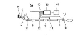
以下、本発明に係る排気ガス分析装置の一実施形態を図面に基づき詳細に説明する。図1は、本実施形態に係る排気ガス分析装置を自動車に搭載した要部構成図、図2は、図1の排気ガス分析装置をエンジンベンチに設置した状態の要部構成図、図3は、排気ガス分析装置のセンサ部の要部を示す斜視図と、センサ部の縦断面図、図4は、センサ部の断面図を含む排気ガス分析装置の要部構成図、図5は、レーザ発振・受光コントローラの要部構成および分析装置を含む排気ガス分析装置の全体構成を示すブロック図である。 Hereinafter, an embodiment of an exhaust gas analyzer according to the present invention will be described in detail with reference to the drawings. FIG. 1 is a main part configuration diagram in which the exhaust gas analyzer according to the present embodiment is mounted on an automobile, FIG. 2 is a main part configuration diagram in a state where the exhaust gas analyzer of FIG. 1 is installed on an engine bench, and FIG. FIG. 4 is a perspective view showing the main part of the sensor part of the exhaust gas analyzer, a longitudinal sectional view of the sensor part, FIG. 4 is a configuration diagram of the main part of the exhaust gas analyzer including the cross-sectional view of the sensor part, and FIG. It is a block diagram which shows the principal part structure of an oscillation and light reception controller, and the whole structure of the exhaust-gas analyzer containing an analyzer.
図1〜5において、本実施形態の排気ガス分析装置は、自動車1に設置されたエンジン2から排出される排気ガスを分析する装置である。また、図2に示すように、エンジンベンチ1Aに設置されたエンジン2の排気ガスを分析する装置である。エンジン2の各気筒から排出される排気ガスは、エキゾーストマニホルド3で合流され、排気管4を通して触媒装置5に導入され、さらにサブマフラー6に導入され、そのあとメインマフラー7を通して排気パイプ8から大気中に放出される。排気経路は、エキゾーストマニホルド3、排気管4、触媒装置5、サブマフラー6、メインマフラー7、排気パイプ8を接合して形成され、エンジン1から排出された排気ガスを触媒装置5で浄化し、サブマフラー6、メインマフラー7により消音、減圧して大気中に放出する。
1 to 5, the exhaust gas analyzer of this embodiment is an apparatus that analyzes exhaust gas discharged from an
排気経路を構成する複数の部材は基本的にはパイプ状の管部材であり、フランジ部同士を対接させてボルト等で接続されている。例えば、触媒装置5は大径の本体部の上流、下流側に排気パイプ部が連結され、これらの排気パイプ部の端部にフランジ部F,Fが溶接等により固着されている。また、サブマフラー6は大径の本体部の上流、下流側に排気パイプ部が連結され、これらの排気パイプ部の端部にフランジ部F,Fが固着されている。なお、末端の排気パイプ8はメインマフラー7に直接溶接等により固着されている。
The plurality of members constituting the exhaust path are basically pipe-like tube members, and are connected by bolts or the like with the flange portions in contact with each other. For example, the
本実施形態の排気ガス分析装置10は、前記の排気経路中の複数箇所に取り付けられた複数のセンサ部11〜14を備えて構成される。第1のセンサ部11は触媒装置5より上流側のエンジン側の排気管4との間に設置され、第2のセンサ部12は触媒装置5の下流側に設置され、第3のセンサ部13はサブマフラー6の下流側に設置されている。そして、第4のセンサ部14はメインマフラー7の下流の排気パイプ8に設置されている。センサ部14は排気パイプの途中に設置されても、排気パイプの末端の開口部に挿入して設置するものでもよい。
The
排気管4や触媒装置5、サブマフラー6、メインマフラー7はフランジ部F,Fをボルトで締め付けることで連結されており、排気経路を構成する部材の間に設置されるセンサ部11,12,13は、フランジ部F,Fで挟まれた状態で設置されている。フランジ部F,Fは、排気経路を構成する部材の両端部に形成され、フランジ部同士の接合面は排気経路の中心線に対して直角に交差している。この結果、センサ部11〜13はフランジ部F,Fに挟まれて排気経路を横切るように設置される。第4のセンサ部14は排気ガスが大気中に放出される直前の分析を行うものであり、メインマフラー7から突出する排気パイプ8の中間部にフランジ部F,Fで挟んで設置してもよい。なお、センサ部の設置数は任意に設定すればよい。
The
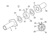
各センサ部11〜14は同一構成であり、1つのセンサ部11について図3,4を参照して説明する。センサ部11は厚さが10〜20mm程度の板材から形成されたセンサベース20を有し、中心部に排気パイプ部の内径と略同じ直径の貫通孔21が形成されている。貫通孔21は排気経路中を通過する排気ガスが通過する。貫通孔21の形状は、排気流れを乱さないように排気パイプ部の内径と同じ直径の円形が好ましい。板材としては金属板材やセラミック製の板材を用いているが、材質については特に問わない。板材には、板厚の中央を端面から貫通孔に向けて貫通する2つのセンサ孔22,23が形成されている。センサ孔は入口側が大径で、貫通孔側は小径となっており、貫通孔21に向けて開口している。
Each sensor part 11-14 is the same structure, and demonstrates the one
また、板状のセンサベース20に形成された貫通孔21の内面に反射面24が形成されている。したがって、円形の貫通孔の直径は排気パイプ部の直径と同じに形成され、円周面の内面が反射面24となっている。貫通孔21の内面を反射面とすることで、センサベースと別の反射部材としてミラー等が不要となり、構成を簡単にすることができると共に、貫通孔の形状が排気パイプ部の断面形状と同じにできるため、排気ガスの流れを乱すことがなく、圧力損失が少なく円滑に排気することができる。
A
貫通孔21の内面に形成された反射面24は鏡面仕上げされた円周面に形成され、この円周面に金やプラチナの薄膜が形成され、その上に保護層として、MgF2やSiO2の薄膜が形成されている。反射面24は、赤外レーザ光を効率良く反射できるように反射率が高いことが望ましい。反射面はエンジンの起動中は排気ガスに晒され、汚れが付着するため、必要に応じてフランジ部F,Fからセンサベース20を取外して清掃することが好ましい。反射面24を覆う保護層を拭くことにより、付着した汚れを容易に清掃することができ、反射率を向上させることができる。
The
センサ部11はレーザ光を照射する照射部として光ファイバ25がセンサ孔22に固定され、光ファイバ25から照射され貫通孔21内に存在する排気ガス中を透過したレーザ光を受光する受光部として、光ファイバ26がセンサ孔23に固定されている。すなわち、センサベース20には照射側の光ファイバ25と受光側の光ファイバ26が固定され、照射側の光ファイバ25から出射された赤外レーザ光は貫通孔21の内面に形成された反射面24で反射され、複数回の反射を繰り返したあと受光側の光ファイバ26に受光される構成となっている。この構成により、照射側の光ファイバ25から照射された赤外レーザ光は、貫通孔21内で反射面24により複数回反射され、長い光路長を経由して受光側の光ファイバ26で受光されるように構成され、貫通孔21内に位置する排気ガス中を長い透過距離で透過する構成となっている。なお、照射側の光ファイバ25と受光側の光ファイバ26とを直径方向に対向させ、光ファイバ25から照射されたレーザ光を反射させずに光ファイバ26で直接受光する構成でもよい。
The
センサベース20はフランジ部F,Fに挟まれた状態で固定され、フランジ部Fとセンサベース20との間にはガスケット27,27が挟まれた状態で図示していないボルト、ナット等により固定される。ガスケット27は石綿等で形成され、排気管の内径と同じ直径の貫通孔が開けられている。この構成により、フランジ部F,Fの間にセンサベース20を挟んで排気経路を接続しても、排気ガスが途中で漏れることはなく、排気経路の長さの増加も少ない。図3,4では、排気管4の下流端に溶接されたフランジ部Fと、触媒装置5の上流側の排気パイプ部5aの端部に溶接されたフランジ部Fとの間に、ガスケット27,27を挟んでセンサベース20が固定される構成である。
The
光ファイバ25,26はレーザ発振・受光コントローラ30に接続され、レーザ発振・受光コントローラ30から出射される赤外レーザ光が光ファイバ25を通してセンサベース20の貫通孔21内に照射され、反射面24で反射された赤外レーザ光が受光側の光ファイバ26で受光され、レーザ発振・受光コントローラ30に入力される構成となっている。レーザ発振・受光コントローラ30から出射された発光強度と、受光された受光強度等がフォトダイオードで検出され、分析装置であるパーソナルコンピュータ40に供給される。このように、排気ガス分析装置10は、複数のセンサ部11〜14と、レーザ発振・受光コントローラ30と、パーソナルコンピュータ40とを備えて構成される。
The
ここで、レーザ発振・受光コントローラ30について、図5を参照して説明する。レーザ発振・受光コントローラ30は、複数の波長の赤外レーザ光を照射する照射装置として、複数のレーザダイオードLD1〜LD5にファンクションジェネレータ等の信号発生器31から複数の周波数の信号を供給し、レーザダイオードLD1〜LD5は各周波数に対応してそれぞれ複数の波長の赤外レーザ光を照射する。レーザ発振・受光コントローラ30の信号発生器31から出力される複数の周波数の信号がレーザダイオードLD1〜LD5に供給されて発光し、例えば波長が1300〜1700nm程度の赤外レーザ光が用いられる。
Here, the laser oscillation /
排気ガス中を透過させる赤外レーザ光の波長は、検出する排気ガス成分に合わせて設定され、一酸化炭素(CO)、二酸化炭素(CO2)、アンモニア(NH3)、メタン(CH4)、水(H2O)を検出する場合は、5つの波長の赤外レーザ光を使用する。例えば、アンモニアを検出するのに適した波長は1530nmであり、一酸化炭素を検出するのに適した波長は1560nmであり、二酸化炭素を検出するのに適した波長は1570nmである。また、メタンを検出するのに適した波長は1680nmであり、水を検出するのに適した波長は1350nmである。このように、排気ガス中を透過させる赤外レーザ光は、複数種類の単波長レーザ光を合波したレーザ光を使用することが好ましい。さらに、他の排気ガス成分のガス濃度を検出する場合は、排気ガス成分の数に合わせて異なる波長の赤外レーザ光を使用する。 The wavelength of the infrared laser beam transmitted through the exhaust gas is set according to the exhaust gas component to be detected, and is carbon monoxide (CO), carbon dioxide (CO 2 ), ammonia (NH 3 ), methane (CH 4 ). When detecting water (H 2 O), infrared laser beams having five wavelengths are used. For example, the wavelength suitable for detecting ammonia is 1530 nm, the wavelength suitable for detecting carbon monoxide is 1560 nm, and the wavelength suitable for detecting carbon dioxide is 1570 nm. The wavelength suitable for detecting methane is 1680 nm, and the wavelength suitable for detecting water is 1350 nm. As described above, it is preferable to use a laser beam obtained by combining a plurality of types of single wavelength laser beams as the infrared laser beam transmitted through the exhaust gas. Furthermore, when detecting the gas concentrations of other exhaust gas components, infrared laser beams having different wavelengths are used in accordance with the number of exhaust gas components.
各レーザダイオードLD1〜LD5から照射されたレーザ光は光ファイバ32…により分波器33…を通して、参照光と測定光に分けられる。そして、5つの分波器33…で分けられた測定光は光ファイバ34Aを通して合波器35で合波され、光ファイバ25を通してセンサ部11〜14の照射部に導光される。照射側の光ファイバ25に入射されるレーザ光は、排気ガスの複数の成分に合わせて複数の波長のレーザ光を合波した赤外レーザ光となっている。また、5つの分波器33…で分けられた参照光は光ファイバ34Bを通して合波器36で合波される。
Laser light emitted from each of the laser diodes LD1 to LD5 is divided into reference light and measurement light by
センサ部11〜14の受光部に接続された受光側の光ファイバ26は分波器37に接続され、光ファイバ38を通して複数の波長に分けられて受光装置としてのフォトダイオードPD1〜PD5に導光され、排気ガス中を透過して減衰した赤外レーザ光を受光する構成となっている。フォトダイオードPD1〜PD5の出力は、例えば図示していないプリアンプで増幅され、A/D変換器を介して分析装置であるパーソナルコンピュータ40に入力される。また、5つの分波器33…で分けられた参照用レーザ光は合波器36で合波され、光ファイバ39を通してフォトダイオードPD6に導光されパーソナルコンピュータ40に入力される。なお、フォトダイオードPD1〜PD5を使用せず、受光された赤外レーザ光は1つのフォトダイオードに導光され、フォトダイオードの出力がパーソナルコンピュータにて複数の波長に分けられて演算を行うように構成してもよい。
The
本発明の排気ガス分析装置10は、例えば赤外レーザ光を排気ガス中に透過させ、入射光の強度と排気ガス中を透過したあとの透過光の強度に基づいて排気ガスの濃度を算出し、排気ガスを分析するものである。すなわち、排気ガスの濃度Cは、以下の数式(1)から算出される。
C=−ln(I/I0)/kL…(1)
The
C = −ln (I / I 0 ) / kL (1)
この数式(1)において、Iは透過光強度、I0は入射光強度、kは吸収率、Lは透過距離である。したがって、参照光である入射光強度(I0)に対する透過光強度(I)の比、シグナル強度(I/I0)に基づいてガス濃度Cは算出される。透過光強度Iは、光ファイバ26を通してフォトダイオードPD1〜PD5から出力され、入射光強度I0は、光ファイバ39を通してフォトダイオードPD6から出力される。
In Equation (1), I is the transmitted light intensity, I 0 is the incident light intensity, k is the absorptance, and L is the transmission distance. Therefore, the gas concentration C is calculated based on the ratio of the transmitted light intensity (I) to the incident light intensity (I 0 ), which is the reference light, and the signal intensity (I / I 0 ). Transmitted light intensity I is output from the photodiode PD1~PD5 through the
前記の如く構成された本実施形態の排気ガス分析装置10の動作について以下に説明する。排気ガスのガス濃度を測定するときは、レーザ発振・受光コントローラ30の信号発生器31を作動させて各レーザダイオードLD1〜LD5に信号を供給して各レーザダイオードLD1〜LD5から所定の波長の赤外レーザ光を発光させる。各レーザダイオードLD1〜LD5から発光された赤外レーザ光は、光ファイバ32…を通して分波器33…に至り、ここで測定光と参照光に分波される。各分波器で分波された測定光は光ファイバ34Aを通して合波器35で合波されて測定用レーザ光となり、センサ部11〜14の照射部に光ファイバ25を通して導光される。また、各分波器で分波された参照光は光ファイバ34Bを通して合波器36で合波されて参照用レーザ光となる。
The operation of the
そして、センサ部の光ファイバ25から照射された測定用レーザ光は、排気ガスが通過している貫通孔21内に照射される。測定用レーザ光は反射面24で反射されることを繰り返して受光部に到達する。なお、図5では、測定用レーザ光が反射面で反射され、光路長が長くなることを示しておらず、破線で略記している。排気ガス中を通り減衰して受光部に到達した測定用レーザ光は光ファイバ26を通って分波器37に導入され、複数の波長成分に合わせて分波される。そして、分波されたあと光ファイバ38を通して測定用フォトダイオードPD1〜PD5に特定の波長に合わせて受光される。また、参照用レーザ光は光ファイバ39を通して参照用フォトダイオードPD6に受光される。このようにして、フォトダイオードPD1〜PD6の出力が分析装置であるパーソナルコンピュータ40に入力される。パーソナルコンピュータ40は、入力されたフォトダイオードPD1〜PD6の出力に基づいて、排気ガスの濃度測定や温度測定を実施して分析する。
And the laser beam for measurement irradiated from the
センサ部11〜14から照射された測定用の赤外レーザ光は、貫通孔21内の排気ガス中を透過して減衰され、反射面24で反射されて再度排気ガス中を透過することでさらに減衰される。このように反射が繰り返されることで光路長が長くなり、排気ガス中の透過距離が長くなることで減衰量が大きくなるため、精度の良い瞬時のガス濃度測定が可能となる。このように参照レーザ光の光強度I0と、測定用レーザ光の透過光強度Iとの比(I/I0)であるシグナル強度を算出し、このシグナル強度比に基づいてガス濃度を算出する。シグナル強度は30%以上となることが好ましい。
The measurement infrared laser light emitted from the
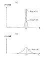
気体は、それぞれ固有の吸収波長帯を持っており、その吸収波長帯には、例えば図6に示すように、多くの吸収線が存在している。図6aは低温のときのシグナル強度(=分子数割合)を示しており、図6bは高温のときのシグナル強度を示している。このように、シグナル強度は温度に依存して変化するため、シグナル強度比を計測することにより、測定時の排気ガスの温度を算出することができる。 Each gas has its own absorption wavelength band, and many absorption lines exist in the absorption wavelength band, for example, as shown in FIG. FIG. 6a shows the signal intensity at the low temperature (= number of molecules), and FIG. 6b shows the signal intensity at the high temperature. Thus, since the signal intensity changes depending on the temperature, the temperature of the exhaust gas at the time of measurement can be calculated by measuring the signal intensity ratio.
そして、図7に示すように、吸収線のうちの1本、例えば波長λ1に対してレーザ光の発振波長を掃引することによって吸収を測定する。この波形と参照レーザ光の波形との比をとることによって、スペクトルプロファイルを測定する。また、温度計測は、前記のスペクトルプロファイルを異なる2つの吸収線λ1、λ2について計測し、それらの面積比A1/A2(またはピークの高さの比P1/P2)をとることにより求めることができる。従来の波長変調法では、図7aに示すように、吸収スペクトルピークの先端の曲率により濃度を算出していたが、本発明では、図7bに示すように、吸収スペクトルの面積により濃度を算出するため、圧力の影響を受けにくいガス濃度の算出が可能となる。 Then, as shown in FIG. 7, the absorption is measured by sweeping the oscillation wavelength of the laser light with respect to one of the absorption lines, for example, the wavelength λ1. The spectrum profile is measured by taking the ratio between this waveform and the waveform of the reference laser beam. Further, the temperature measurement can be obtained by measuring the spectrum profile for two different absorption lines λ1 and λ2 and taking the area ratio A1 / A2 (or the peak height ratio P1 / P2). . In the conventional wavelength modulation method, the concentration is calculated based on the curvature of the tip of the absorption spectrum peak as shown in FIG. 7a. In the present invention, the concentration is calculated based on the area of the absorption spectrum as shown in FIG. 7b. Therefore, it is possible to calculate a gas concentration that is not easily affected by pressure.
本実施形態の排気ガス分析装置10では、エンジン2の排気経路の複数箇所で排気ガスのガス濃度や温度をリアルタイムで測定することができ、エンジンから排出された直後の排気ガスの温度やガス濃度、触媒装置5、サブマフラー6、メインマフラー7を通過したあとの排気ガスの温度やガス濃度、排気パイプ8から大気中に放出される直前の排気ガスの状態等を瞬時に測定できる装置である。このため、エンジンの開発や、エンジンに付属する浄化装置等の開発において、排気経路の途中個所での排気ガス濃度を測定できるため、タイムリーな測定ができて開発期間を大幅に短縮できる。そして、測定に際して基準ガスが必要なく、低コストで排気ガス分析が行える。
In the
また、本実施形態の排気ガス分析装置10は小型で、排気経路に容易に設置できるため、自動車等に容易に車載することができる。すなわち、排気経路に固定されるセンサ部11〜14は板状のセンサベース20が薄型に構成されており、排気経路の流体抵抗等の変化がほとんど無い状態で設置できる。この排気ガス分析装置10は高温状態でも測定できるため、エンジン2から排出された直後の排気ガスの温度やガス濃度を測定して、排気ガスを分析することができる。また、レーザ光の波長を増やすことにより、さらに排気ガス中に含まれる多成分の分析が容易に行える。
Moreover, since the
本発明の他の実施形態を図8に基づき詳細に説明する。図8は本発明に係る排気ガス分析装置に使用するセンサ部の他の実施形態の要部断面図である。なお、この実施形態は前記した実施形態に対し、センサ部の赤外レーザ光を反射する反射面が異なることを特徴とする。すなわち、赤外レーザ光を反射する反射面は、対向して配置した2枚の反射板から構成され、2枚の反射板間で反射を繰り返すように構成している。そして、他の実質的に同等の構成については同じ符号を付して詳細な説明は省略する。 Another embodiment of the present invention will be described in detail with reference to FIG. FIG. 8 is a cross-sectional view of the main part of another embodiment of the sensor unit used in the exhaust gas analyzer according to the present invention. This embodiment is characterized in that the reflecting surface for reflecting the infrared laser beam of the sensor unit is different from the above-described embodiment. That is, the reflecting surface that reflects the infrared laser light is composed of two reflecting plates arranged opposite to each other, and is configured to repeat reflection between the two reflecting plates. Other substantially equivalent configurations are denoted by the same reference numerals, and detailed description thereof is omitted.
図8において、この実施形態では、センサ部15のセンサベース50には、その中心部に排気ガスを通過させる貫通孔51が形成され、貫通孔51内には、対向して上下2枚の反射板52,53が固定されている。2枚の反射板は平行状態に固定され、照射側の光ファイバ25から出射される赤外レーザ光が先ず下方の反射板53により上方に向けて反射され、次いで上方の反射板52により下方に向けて反射され、2枚の反射板52,53により交互に反射されることで、受光側の光ファイバ26に到達するように構成されている。センサベース50の厚さは、前記の実施形態と同様に10〜20mmの薄い板材が使用されており、材質は金属あるいはセラミックが好ましい。このセンサベース50は、図示していないフランジ部F,Fに挟まれて固定されるものであり、外形の左右の半円状の切欠きはフランジ部同士を接続するボルトに対応している。
In FIG. 8, in this embodiment, a
照射側の光ファイバ25は、反射板の垂直線に対して、例えば6度程度外側に傾斜して固定され、受光側の光ファイバ26も同様に6度程度外側に傾斜して固定されている。2つの光ファイバ25,26と2枚の反射板52,53が傾斜状態に配置されることで、照射側の光ファイバ25から出射された赤外レーザ光は上下の反射板で交互に反射されることを繰り返し、最終的に赤外レーザ光は排気ガス中を長い光路長で透過して受光側の光ファイバ26に受光されるように構成されている。この結果、中央の貫通孔の直径が50mm程度とすると、赤外レーザ光は9回反射を繰り返して光路長は約450mm程度の長いものとなり、排気ガス中を透過して減衰量が大きくなる。
The
反射板52,53は長方形状の平板に形成され、ベースとなる基板は熱膨張の小さいSiCあるいはSiO2が用いられる。この基板に反射面として金やプラチナの薄膜が形成され、その上に保護層として、MgF2やSiO2の薄膜が形成されている。本実施形態では、反射板52,53はセンサベース50に接着等により固定されているが、反射板はエンジンの起動中は排気ガスに晒され汚れが付着するため、取外して清掃できるように、ねじ止め、あるいはばね等による固定で着脱可能に固定すると好適である。
The reflecting
この実施形態に示すセンサ部15では、照射部である光ファイバ25から照射された赤外レーザ光は対向する反射板52,53で交互に反射が繰り返され、光路長が長くなって排気ガス中のレーザ光の透過距離を大きくすることができる。この構成によれば、赤外レーザ光は排気ガス中を透過する距離が長くなり減衰を大きくできるため、精度の良いガス濃度測定が瞬時に行える。また、反射板が平板であり、作製が容易で、センサベースからの着脱や交換が容易に行える。
In the
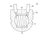
本発明の排気ガス分析装置のセンサ部は、図9に示すセンサ部16のように、エンジン2のシリンダヘッド2aとエキゾーストマニホルド3との間に、設置することができる。なお、図9では1つのセンサ部16のみを拡大して示しているが、4気筒の場合は4つの排気孔2bに対して4つのセンサ部16を設置する。センサ部16のセンサベース55は、その両面にガスケットが対接した状態でシリンダヘッド2aとエキゾーストマニホルド3との間に挟まれて固定される。エキゾーストマニホルド3はエンジン2の各気筒から排出される排気ガスを合流して排気管4に送る機能を有している。
The sensor unit of the exhaust gas analyzer of the present invention can be installed between the
エキゾーストマニホルド3は、シリンダヘッド2aにボルト等により上流側のフランジ部3aが固定される。また、エキゾーストマニホルド3の他端側は排気管4に連結するためのフランジ部3bが形成されている。センサ部16のセンサベース55には照射側の光ファイバ25と受光側の光ファイバ26が固定され、光ファイバ25,26はレーザ発振・受光コントローラ30に接続される。センサ部16を構成する長方形のセンサベース55には長方形の貫通孔56が形成され、貫通孔の上下面に形成された反射面で測定用の赤外レーザ光が交互に反射され、光路長が長くなるように構成されている。
In the
前記した排気ガス分析装置のセンサ部11〜14と別のセンサ部16は、エキゾーストマニホルド3の上流側のフランジ部3aと、シリンダブロック2aとの間に挟まれた状態で設置される。このように設置されたセンサ部16によれば、エンジン2から排出された直後の排気ガスがエキゾーストマニホルド3で合流される前の段階で、排気ガスの温度やガス濃度を測定することができる。このようにセンサ部16を設置すると、エンジン2の各気筒から排出される排気ガスの温度やガス濃度を直接測定することができ、気筒ごとに排出される排気ガスを分析できるため、エンジンの燃焼状態を気筒ごとに確認することができる。
The
また、センサ部のセンサベースに形成された貫通孔の形状は円形や長方形に限らず、図10に示すように多角形状でもよい。この場合は、センサ部17を構成するセンサベース60には5角形の貫通孔61が形成され、5角形を構成する各平面に形成された反射面62で順次、赤外レーザ光を反射して、排気ガス中を透過するレーザ光の透過距離を長くすることができる。貫通孔の形状は図示の5角形に限らず、さらに面数を増やして排気ガス中の透過距離を増加させることができる。センサベースの外形は円形に限らず、長方形等、適宜の形状とすることができる。また、レーザ光の反射面による反射回数は限定されず、多角形で形成された貫通孔の内面で多数回反射させて、透過距離を長くすることができる。
Further, the shape of the through hole formed in the sensor base of the sensor unit is not limited to a circle or a rectangle, but may be a polygon as shown in FIG. In this case, a pentagonal through-
以上、本発明の実施形態について詳述したが、本発明は、前記の実施形態に限定されるものではなく、特許請求の範囲に記載された本発明の精神を逸脱しない範囲で、種々の設計変更を行うことができるものである。例えば、排気ガスの成分として、窒素酸化物(NOx)の測定を行うこともできる。この場合は、排気ガス中を透過させる赤外レーザ光として、NOxに適した波長(例えば1800nm)を用いることは勿論である。また、照射部から照射されるレーザ光は赤外レーザ光に限られず、可視レーザ光や紫外レーザ光でもよい。 Although the embodiments of the present invention have been described in detail above, the present invention is not limited to the above-described embodiments, and various designs can be made without departing from the spirit of the present invention described in the claims. It can be changed. For example, nitrogen oxide (NOx) can be measured as an exhaust gas component. In this case, as a matter of course, a wavelength (for example, 1800 nm) suitable for NOx is used as the infrared laser beam that passes through the exhaust gas. The laser light emitted from the irradiation unit is not limited to infrared laser light, and may be visible laser light or ultraviolet laser light.
センサ部のセンサベースに光ファイバを介してレーザ光の照射部と受光部を備える例を示したが、センサベースに直接レーザダイオード等の照射部やフォトダイオード等の受光部を装着してレーザ光の照射部および受光部としてもよい。この場合は、光ファイバが不要となり、レーザダイオードに信号を入力する入力信号線と、フォトダイオードから出力される出力信号線が必要となる。また、反射面として、金やプラチナの薄膜を形成する例を示したが、酸化チタン等の薄膜を形成してもよく、耐熱性に優れ、鏡面加工できるものであれば材質は特定されない。 Although an example in which the sensor base of the sensor unit is provided with a laser beam irradiation unit and a light receiving unit via an optical fiber has been shown, a laser beam is directly attached to the sensor base and a light receiving unit such as a photodiode is attached to the laser beam. It is good also as an irradiation part and light-receiving part. In this case, an optical fiber is unnecessary, and an input signal line for inputting a signal to the laser diode and an output signal line output from the photodiode are required. Moreover, although the example which forms the thin film of gold | metal | money or platinum as a reflective surface was shown, thin films, such as a titanium oxide, may be formed, and if it is excellent in heat resistance and can be mirror-finished, a material will not be specified.
本発明の活用例として、この排気ガス分析装置を用いてボイラー等の燃焼装置の排気ガス分析を行うことができ、自動車の排気ガス分析の他に船舶等で使用する内燃機関の排気ガス分析の用途にも適用できる。 As an application example of the present invention, it is possible to perform an exhaust gas analysis of a combustion apparatus such as a boiler using this exhaust gas analysis apparatus. In addition to an automobile exhaust gas analysis, an exhaust gas analysis of an internal combustion engine used in a ship etc. It can also be applied to applications.
1:自動車、1A:エンジンベンチ、2:エンジン、2a:シリンダヘッド、3:エキゾーストマニホルド(排気経路)、3a:フランジ部、4:排気管(排気経路)、5:触媒装置(排気経路)、6:サブマフラー(排気経路)、7:メインマフラー(排気経路)、8:排気パイプ(排気経路)、10:排気ガス分析装置、11〜17:センサ部、20,50,55,60:センサベース、21,51,56,61:貫通孔、24,62:反射面、25:光ファイバ(発光部)、26:光ファイバ(受光部)、30:レーザ発振・受光コントローラ、31:信号発生器、35,36:合波器、37:分波器、40:パーソナルコンピュータ(分析装置)、52,53:反射板、LD1〜LD5:レーザダイオード(発光部)、PD1〜PD6:フォトダイオード(受光部)、F:フランジ部
1: automobile, 1A: engine bench, 2: engine, 2a: cylinder head, 3: exhaust manifold (exhaust path), 3a: flange, 4: exhaust pipe (exhaust path), 5: catalyst device (exhaust path), 6: sub muffler (exhaust path), 7: main muffler (exhaust path), 8: exhaust pipe (exhaust path), 10: exhaust gas analyzer, 11-17: sensor unit, 20, 50, 55, 60: sensor Base, 21, 51, 56, 61: Through hole, 24, 62: Reflecting surface, 25: Optical fiber (light emitting part), 26: Optical fiber (light receiving part), 30: Laser oscillation / light receiving controller, 31:
Claims (3)
前記センサ部が、前記排気ガスの通過する貫通孔と、前記貫通孔内にレーザ光を照射するレーザ光照射部と、前記レーザ光照射部から照射された光を反射する反射面又は反射板を前記貫通孔の内周に設け、前記反射面又は反射板で反射された光を受光する受光部と、を有しており、
前記センサ部は、排気経路中を通過する排気ガスが前記貫通孔を通過するように取り付け可能であり、前記排気経路は、複数の管部材を接合して形成されており、前記センサ部の貫通孔の径が、前記管部材の内径と略等しい大きさに構成されるとともに、前記センサ部が、前記複数の管部材の端部に設けられたフランジ部に挟まれて取付けられる排気ガス分析装置。 An exhaust gas analyzer that is attached to a plurality of locations in an exhaust path through which exhaust gas discharged from an engine flows, and includes a plurality of sensor units that measure component concentrations in the exhaust gas,
The sensor unit includes a through-hole through which the exhaust gas passes, a laser beam irradiation unit that irradiates laser light into the through-hole, and a reflective surface or a reflection plate that reflects light emitted from the laser beam irradiation unit. A light receiving portion that is provided on an inner periphery of the through hole and receives light reflected by the reflection surface or the reflection plate;
The sensor section, Ri can der mounted so that the exhaust gas passing through the exhaust path passes through the through-hole, the exhaust path is formed by joining a plurality of tubular members, said sensor portion the diameter of the through hole, while being configured to substantially equal size as the inner diameter of the pipe member, wherein the sensor unit is provided that the exhaust gas attached sandwiched flange portion provided at an end portion of said plurality of tubular members Analysis equipment.
Priority Applications (1)
| Application Number | Priority Date | Filing Date | Title |
|---|---|---|---|
| JP2004379610A JP4485345B2 (en) | 2004-12-28 | 2004-12-28 | Exhaust gas analyzer |
Applications Claiming Priority (1)
| Application Number | Priority Date | Filing Date | Title |
|---|---|---|---|
| JP2004379610A JP4485345B2 (en) | 2004-12-28 | 2004-12-28 | Exhaust gas analyzer |
Publications (2)
| Publication Number | Publication Date |
|---|---|
| JP2006184180A JP2006184180A (en) | 2006-07-13 |
| JP4485345B2 true JP4485345B2 (en) | 2010-06-23 |
Family
ID=36737405
Family Applications (1)
| Application Number | Title | Priority Date | Filing Date |
|---|---|---|---|
| JP2004379610A Expired - Fee Related JP4485345B2 (en) | 2004-12-28 | 2004-12-28 | Exhaust gas analyzer |
Country Status (1)
| Country | Link |
|---|---|
| JP (1) | JP4485345B2 (en) |
Families Citing this family (17)
| Publication number | Priority date | Publication date | Assignee | Title |
|---|---|---|---|---|
| US8208143B2 (en) | 2005-04-28 | 2012-06-26 | Toyota Jidosha Kabushiki Kaisha | Exhaust gas analyzer |
| JP4199766B2 (en) | 2005-12-16 | 2008-12-17 | トヨタ自動車株式会社 | Exhaust gas analysis method and exhaust gas analyzer |
| JP4594277B2 (en) | 2006-05-31 | 2010-12-08 | トヨタ自動車株式会社 | Sensor unit in exhaust gas analyzer |
| JP4732277B2 (en) * | 2006-08-23 | 2011-07-27 | トヨタ自動車株式会社 | Gas analyzer and gas analysis method |
| JP4906477B2 (en) * | 2006-11-06 | 2012-03-28 | トヨタ自動車株式会社 | Gas analyzer and gas analysis method |
| JP5259950B2 (en) * | 2006-12-14 | 2013-08-07 | 三菱重工業株式会社 | Processing device for exhaust gas analysis and exhaust gas analysis method |
| JP4879053B2 (en) * | 2007-03-20 | 2012-02-15 | トヨタ自動車株式会社 | Exhaust gas analyzer |
| JP4949999B2 (en) * | 2007-11-05 | 2012-06-13 | トヨタ自動車株式会社 | Exhaust gas analyzer |
| JP5339179B2 (en) * | 2008-06-20 | 2013-11-13 | 住友電気工業株式会社 | Infrared detection type gas sensor and exhaust gas purification apparatus using the same |
| JP2010174863A (en) * | 2009-02-02 | 2010-08-12 | Yamaha Motor Co Ltd | Internal combustion engine, transport equipment, and ring-shaped member |
| JP5270455B2 (en) * | 2009-05-29 | 2013-08-21 | トヨタ自動車株式会社 | Exhaust gas analyzer |
| JP2014032068A (en) * | 2012-08-02 | 2014-02-20 | Koptic Inc | Gas concentration measuring device |
| JP2014163237A (en) * | 2013-02-21 | 2014-09-08 | Kobelco Contstruction Machinery Ltd | Exhaust pipe structure of construction machine |
| KR101518968B1 (en) * | 2014-03-28 | 2015-05-11 | (주)켄텍 | Real time Measurement Device in the Exhaust gas of the Motor Vehicle on the Move |
| CN110553986A (en) * | 2019-08-26 | 2019-12-10 | 国网吉林省电力有限公司四平供电公司 | Multifunctional comprehensive analyzer for each component of decomposition product in SF6 gas |
| JP7357918B2 (en) | 2019-10-28 | 2023-10-10 | ゼネラルパッカー株式会社 | Gas concentration measuring device inside packaging bag |
| CN114324191A (en) * | 2022-01-07 | 2022-04-12 | 柳州职业技术学院 | Smell survey system based on intelligent control |
Citations (7)
| Publication number | Priority date | Publication date | Assignee | Title |
|---|---|---|---|---|
| JPH02280032A (en) * | 1989-04-20 | 1990-11-16 | Agency Of Ind Science & Technol | Continuous evaluation device for exhaust smoke processor |
| JPH0843305A (en) * | 1994-07-29 | 1996-02-16 | Nippon Kagaku Kogyo Kk | Smoke density measuring device |
| JP2001066250A (en) * | 1999-08-30 | 2001-03-16 | Toyota Central Res & Dev Lab Inc | Gas detection apparatus |
| JP2001159605A (en) * | 1999-12-01 | 2001-06-12 | Nippon Sanso Corp | Laser spectroscopic analyzer and analyzing method |
| JP2003014637A (en) * | 2001-06-29 | 2003-01-15 | Ishikawajima Harima Heavy Ind Co Ltd | So3 densitometer |
| JP2003042950A (en) * | 2001-07-25 | 2003-02-13 | Oyo Kogaku Kenkyusho | Instrument for measuring gas component |
| JP2003232731A (en) * | 2002-02-06 | 2003-08-22 | Horiba Ltd | Smoke measuring system |
-
2004
- 2004-12-28 JP JP2004379610A patent/JP4485345B2/en not_active Expired - Fee Related
Patent Citations (7)
| Publication number | Priority date | Publication date | Assignee | Title |
|---|---|---|---|---|
| JPH02280032A (en) * | 1989-04-20 | 1990-11-16 | Agency Of Ind Science & Technol | Continuous evaluation device for exhaust smoke processor |
| JPH0843305A (en) * | 1994-07-29 | 1996-02-16 | Nippon Kagaku Kogyo Kk | Smoke density measuring device |
| JP2001066250A (en) * | 1999-08-30 | 2001-03-16 | Toyota Central Res & Dev Lab Inc | Gas detection apparatus |
| JP2001159605A (en) * | 1999-12-01 | 2001-06-12 | Nippon Sanso Corp | Laser spectroscopic analyzer and analyzing method |
| JP2003014637A (en) * | 2001-06-29 | 2003-01-15 | Ishikawajima Harima Heavy Ind Co Ltd | So3 densitometer |
| JP2003042950A (en) * | 2001-07-25 | 2003-02-13 | Oyo Kogaku Kenkyusho | Instrument for measuring gas component |
| JP2003232731A (en) * | 2002-02-06 | 2003-08-22 | Horiba Ltd | Smoke measuring system |
Also Published As
| Publication number | Publication date |
|---|---|
| JP2006184180A (en) | 2006-07-13 |
Similar Documents
| Publication | Publication Date | Title |
|---|---|---|
| JP4673887B2 (en) | Exhaust gas analyzer | |
| JP4227991B2 (en) | Exhaust gas analyzer and exhaust gas analysis method | |
| JP4485345B2 (en) | Exhaust gas analyzer | |
| JP4199766B2 (en) | Exhaust gas analysis method and exhaust gas analyzer | |
| JP4713227B2 (en) | Exhaust gas analyzer and exhaust gas analysis method | |
| JP4732277B2 (en) | Gas analyzer and gas analysis method | |
| JP4781039B2 (en) | Gas analyzer | |
| JP4566070B2 (en) | Exhaust gas analyzer | |
| JP2009243968A (en) | Exhaust gas analyzer and analyzing method | |
| JP5038923B2 (en) | Exhaust gas analyzer | |
| JP2013061358A (en) | Exhaust gas analyzer and exhaust gas analyzing method | |
| JP4490333B2 (en) | Exhaust gas analyzer | |
| WO2007119872A1 (en) | Exhaust gas analyzer | |
| JP4949999B2 (en) | Exhaust gas analyzer | |
| JP4878981B2 (en) | Gas analyzer |
Legal Events
| Date | Code | Title | Description |
|---|---|---|---|
| A621 | Written request for application examination |
Free format text: JAPANESE INTERMEDIATE CODE: A621 Effective date: 20070301 |
|
| A977 | Report on retrieval |
Free format text: JAPANESE INTERMEDIATE CODE: A971007 Effective date: 20090417 |
|
| A131 | Notification of reasons for refusal |
Free format text: JAPANESE INTERMEDIATE CODE: A131 Effective date: 20090428 |
|
| A521 | Written amendment |
Free format text: JAPANESE INTERMEDIATE CODE: A523 Effective date: 20090629 |
|
| A131 | Notification of reasons for refusal |
Free format text: JAPANESE INTERMEDIATE CODE: A131 Effective date: 20091027 |
|
| A521 | Written amendment |
Free format text: JAPANESE INTERMEDIATE CODE: A523 Effective date: 20091224 |
|
| TRDD | Decision of grant or rejection written | ||
| A01 | Written decision to grant a patent or to grant a registration (utility model) |
Free format text: JAPANESE INTERMEDIATE CODE: A01 Effective date: 20100316 |
|
| A01 | Written decision to grant a patent or to grant a registration (utility model) |
Free format text: JAPANESE INTERMEDIATE CODE: A01 |
|
| A61 | First payment of annual fees (during grant procedure) |
Free format text: JAPANESE INTERMEDIATE CODE: A61 Effective date: 20100324 |
|
| R151 | Written notification of patent or utility model registration |
Ref document number: 4485345 Country of ref document: JP Free format text: JAPANESE INTERMEDIATE CODE: R151 |
|
| FPAY | Renewal fee payment (event date is renewal date of database) |
Free format text: PAYMENT UNTIL: 20130402 Year of fee payment: 3 |
|
| FPAY | Renewal fee payment (event date is renewal date of database) |
Free format text: PAYMENT UNTIL: 20130402 Year of fee payment: 3 |
|
| FPAY | Renewal fee payment (event date is renewal date of database) |
Free format text: PAYMENT UNTIL: 20140402 Year of fee payment: 4 |
|
| R250 | Receipt of annual fees |
Free format text: JAPANESE INTERMEDIATE CODE: R250 |
|
| R250 | Receipt of annual fees |
Free format text: JAPANESE INTERMEDIATE CODE: R250 |
|
| R250 | Receipt of annual fees |
Free format text: JAPANESE INTERMEDIATE CODE: R250 |
|
| R250 | Receipt of annual fees |
Free format text: JAPANESE INTERMEDIATE CODE: R250 |
|
| R250 | Receipt of annual fees |
Free format text: JAPANESE INTERMEDIATE CODE: R250 |
|
| S111 | Request for change of ownership or part of ownership |
Free format text: JAPANESE INTERMEDIATE CODE: R313117 |
|
| R350 | Written notification of registration of transfer |
Free format text: JAPANESE INTERMEDIATE CODE: R350 |
|
| LAPS | Cancellation because of no payment of annual fees |