JP4467727B2 - Electronic device connection method, electronic device, and storage medium storing operation processing program thereof - Google Patents
Electronic device connection method, electronic device, and storage medium storing operation processing program thereof Download PDFInfo
- Publication number
- JP4467727B2 JP4467727B2 JP2000222193A JP2000222193A JP4467727B2 JP 4467727 B2 JP4467727 B2 JP 4467727B2 JP 2000222193 A JP2000222193 A JP 2000222193A JP 2000222193 A JP2000222193 A JP 2000222193A JP 4467727 B2 JP4467727 B2 JP 4467727B2
- Authority
- JP
- Japan
- Prior art keywords
- electronic device
- control signal
- input
- output
- command
- Prior art date
- Legal status (The legal status is an assumption and is not a legal conclusion. Google has not performed a legal analysis and makes no representation as to the accuracy of the status listed.)
- Expired - Fee Related
Links
Images


Classifications
-
- G—PHYSICS
- G06—COMPUTING; CALCULATING OR COUNTING
- G06F—ELECTRIC DIGITAL DATA PROCESSING
- G06F12/00—Accessing, addressing or allocating within memory systems or architectures
- G06F12/02—Addressing or allocation; Relocation
- G06F12/06—Addressing a physical block of locations, e.g. base addressing, module addressing, memory dedication
- G06F12/0646—Configuration or reconfiguration
- G06F12/0653—Configuration or reconfiguration with centralised address assignment
- G06F12/0661—Configuration or reconfiguration with centralised address assignment and decentralised selection
-
- G—PHYSICS
- G05—CONTROLLING; REGULATING
- G05B—CONTROL OR REGULATING SYSTEMS IN GENERAL; FUNCTIONAL ELEMENTS OF SUCH SYSTEMS; MONITORING OR TESTING ARRANGEMENTS FOR SUCH SYSTEMS OR ELEMENTS
- G05B19/00—Programme-control systems
- G05B19/02—Programme-control systems electric
- G05B19/04—Programme control other than numerical control, i.e. in sequence controllers or logic controllers
- G05B19/042—Programme control other than numerical control, i.e. in sequence controllers or logic controllers using digital processors
- G05B19/0423—Input/output
-
- H—ELECTRICITY
- H04—ELECTRIC COMMUNICATION TECHNIQUE
- H04N—PICTORIAL COMMUNICATION, e.g. TELEVISION
- H04N23/00—Cameras or camera modules comprising electronic image sensors; Control thereof
- H04N23/60—Control of cameras or camera modules
- H04N23/66—Remote control of cameras or camera parts, e.g. by remote control devices
-
- H—ELECTRICITY
- H04—ELECTRIC COMMUNICATION TECHNIQUE
- H04N—PICTORIAL COMMUNICATION, e.g. TELEVISION
- H04N7/00—Television systems
- H04N7/18—Closed-circuit television [CCTV] systems, i.e. systems in which the video signal is not broadcast
- H04N7/181—Closed-circuit television [CCTV] systems, i.e. systems in which the video signal is not broadcast for receiving images from a plurality of remote sources
-
- G—PHYSICS
- G05—CONTROLLING; REGULATING
- G05B—CONTROL OR REGULATING SYSTEMS IN GENERAL; FUNCTIONAL ELEMENTS OF SUCH SYSTEMS; MONITORING OR TESTING ARRANGEMENTS FOR SUCH SYSTEMS OR ELEMENTS
- G05B2219/00—Program-control systems
- G05B2219/20—Pc systems
- G05B2219/21—Pc I-O input output
- G05B2219/21028—Address of module determined by position
-
- G—PHYSICS
- G05—CONTROLLING; REGULATING
- G05B—CONTROL OR REGULATING SYSTEMS IN GENERAL; FUNCTIONAL ELEMENTS OF SUCH SYSTEMS; MONITORING OR TESTING ARRANGEMENTS FOR SUCH SYSTEMS OR ELEMENTS
- G05B2219/00—Program-control systems
- G05B2219/20—Pc systems
- G05B2219/21—Pc I-O input output
- G05B2219/21033—Serial transfer address to each module, decrement, if zero module found
-
- G—PHYSICS
- G05—CONTROLLING; REGULATING
- G05B—CONTROL OR REGULATING SYSTEMS IN GENERAL; FUNCTIONAL ELEMENTS OF SUCH SYSTEMS; MONITORING OR TESTING ARRANGEMENTS FOR SUCH SYSTEMS OR ELEMENTS
- G05B2219/00—Program-control systems
- G05B2219/20—Pc systems
- G05B2219/21—Pc I-O input output
- G05B2219/21035—Identification with serial header
-
- G—PHYSICS
- G05—CONTROLLING; REGULATING
- G05B—CONTROL OR REGULATING SYSTEMS IN GENERAL; FUNCTIONAL ELEMENTS OF SUCH SYSTEMS; MONITORING OR TESTING ARRANGEMENTS FOR SUCH SYSTEMS OR ELEMENTS
- G05B2219/00—Program-control systems
- G05B2219/20—Pc systems
- G05B2219/21—Pc I-O input output
- G05B2219/21039—Slaves, modules in daisy chain, each handles control data, transmits to next
Landscapes
- Engineering & Computer Science (AREA)
- Multimedia (AREA)
- Signal Processing (AREA)
- Physics & Mathematics (AREA)
- General Physics & Mathematics (AREA)
- Theoretical Computer Science (AREA)
- General Engineering & Computer Science (AREA)
- Automation & Control Theory (AREA)
- Selective Calling Equipment (AREA)
- Studio Devices (AREA)
- Small-Scale Networks (AREA)
Description
【0001】
【発明の属する技術分野】
本発明は、例えば、カメラなどの複数の電子機器を統括的に制御する電子機器の接続方法に関するものである。
【0002】
【従来の技術】
従来、RS−232Cなどの規格を用いて、パーソナルコンピュータ(PC)からカメラなどの電子機器を制御する技術が知られている。
【0003】
このようなRS−232Cの規格を用いた場合、PCに複数のコネクタを有さなければ複数の電子機器の制御に対応することができなかった。
【0004】
このような問題を解決するため、特許番号第2867649号では、複数の電子機器をシリアルに接続して制御する方法が開示されている。
【0005】
【発明が解決しようとする課題】
しかしながら、特許番号第2867649号では、電子機器に対する制御信号を送受信する信号線の他に、後段に他の接続装置が接続されているかどうかを判定するための端子「3f」が必要となる。本発明では、このような問題を解決するため、信号線を増加させずに複数の電子機器をシリアルに接続して制御可能な電子機器の制御方法を提供することを目的とする。
【0006】
【課題を解決するための手段】
上記の目的を達成するため、本発明の電子機器は、コンピュータよりシリアルに接続され、制御コマンドおよび第1の制御信号、第2の制御信号を互いに送受信することができ、該制御コマンドの送受信が統括的に制御される電子機器であって、前段の電子機器に接続される第1の入出力手段と、後段の電子機器に接続される第2の入出力手段と、前段の電子機器から前記第1の入出力手段を介して第1の制御信号が入力されたことに応じて、前記第2の入出力手段を介して後段に接続される電子機器に新たに第1の制御信号を出力し、後段に接続される電子機器への前記第1の制御信号の出力に対して第2の制御信号が入力されたかどうかを判断し、第2の制御信号が入力されなかったと判断された場合、前記電子機器が末端に接続されていることを前記第1の入出力手段を介して前記コンピュータに出力する処理手段を有し、所定の周期ごとに前記コンピュータより第1の制御信号が出力されることを特徴としている。
また、本発明のコンピュータは、電子機器がシリアルに接続され、該電子機器に対して制御コマンドおよび所定の制御信号を送受信することにより、前記電子機器を統括的に制御するコンピュータであって、前記コンピュータのID番号を付加した所定の制御信号を出力し、該所定の制御信号に対応するコマンドが入力されたかどうかを確認し、前記コマンドが入力されたことが確認された場合、該コマンドに基づいて前記電子機器の接続状態を認識する処理手段を有し、所定の周期ごとに前記所定の制御信号を出力することを特徴としている。
また、本発明の電子機器の接続方法は、コンピュータよりシリアルに接続され、制御コマンドおよび第1の制御信号、第2の制御信号を互いに送受信することができ、該制御コマンドの送受信が統括的に制御される電子機器の接続方法であって、前記コンピュータより前記第1の制御信号が出力され、前記電子機器において、前記コンピュータまたは前段の電子機器から第1の制御信号が入力されたことに応じて、前記第1の制御信号のID番号に基づいて前記電子機器のID番号を設定し、後段に接続されるべき電子機器に新たに第1の制御信号を出力し、後段に接続されるべき電子機器への前記第1の制御信号の出力に対して第2の制御信号が入力されたかどうかを判断し、第2の制御信号が入力されなかった場合、前記コンピュータに前記電子機器のID番号を出力して、前記電子機器が接続の末端であることを前記コンピュータに出力することにより、前記コンピュータに電子機器の接続状態を認識させることを特徴としている。
【0013】
【発明の実施の形態】
以下、添付の図面に沿って本発明の実施の形態を説明する。
【0014】
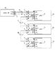
図1は、本実施の形態のパーソナルコンピュータ(PC)からRS−232Cによってシリアルに接続された電子機器を制御するシステムの一例を示す図である。本実施の形態では、電子機器としてパン,チルト制御可能なカメラを例にあげる。
【0015】
カメラ50,60,70は、パン,チルト制御可能なカメラである。HOSTPC40は、パーソナルコンピュータなどによって構成され、直接接続されているカメラ50に対して後述の制御コマンドおよびカスケード接続コマンドを出力する。
【0016】
カメラ50,60,70は、制御コマンドおよびカスケード接続コマンドを入出力する第1の入出力端子3,第2の入出力端子5をそれぞれ有する。第1の入出力端子3は、出力ポート3a,入力ポート3bを有する。また、第2の入出力端子5は、出力ポート5a,入力ポート5bを有する。
【0017】
また、カメラ50,60,70は、バッファメモリ(不図示)を有するCPUを有する。CPU9は、第1の入出力端子3および第2の入出力端子5に対してコマンドを授受するためのポート(端子)9a〜dを有する。また、カメラ50,60,70は、ポート9cの信号に基づいて切り換えを行なうスイッチ11を有する。
【0018】
また、HOST PC40は、制御コマンドおよびカスケード接続コマンドを入出力する入出力端子4を有する。入出力端子4は、出力ポート4a,入力ポート4bを有する。
【0019】
ケーブル10は、HOST PC40およびカメラ50とのコマンドの授受を行なうためのものである。また、ケーブル20は、カメラ50およびカメラ60とのコマンドの授受を行なうためのものである。また、ケーブル30は、カメラ60およびカメラ50とのコマンドの授受を行なうためのものである。
【0020】
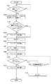
図8は、RS−232Cによってシリアル接続されたカメラにおいて、カメラの接続状態をHOST PC40が認識するためのカスケード接続コマンドが入力された場合のCPU9の動作処理フローチャートである。カスケード接続コマンドとは、HOST PC40が接続されるカメラに対してIDを設定させ、設定させたカメラのIDを認識するためのものである。
【0021】
S101において、ポート3b,9bを介してカスケード接続コマンドが受信されたかどうかを判断する。カスケード接続コマンドが受信された場合、S102に進む。
【0022】
S102において、受信されたカスケード接続コマンドを確認し、「送信元の機器(カメラもしくはHOST PC40)のID番号+1」を自分のID番号に設定して、不図示のバッファメモリに格納する。
【0023】
S103において、ポート3aとポート9aとが接続されるようにスイッチ11が切り換えられているかどうか確認する。ポート3aとポート9aとが接続されている場合、S105に進む。ポート3aとポート9aとが接続されていない場合、S104に進み、ポート9cから制御信号を出力することにより、スイッチ11を切り換えてポート3aとポート9aとを接続させる。
【0024】
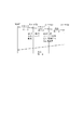
S105において、カスケード接続コマンドの送信元の機器に対してポート9aを介してポート3aからAckコマンドを出力する。なお、図2に示すように、Ackコマンドは、ヘッダー,S102において設定された送信元機器ID番号,送信先ID番号,送信元機器に関する情報を示すステータス情報,ターミネーターによってパケット構成されている。
【0025】
Ackコマンド出力後、S106において、ポート9cから制御信号を出力することにより、スイッチ11を切り換えてポート3aとポート5bとを接続させる。さらに、S107において、‘送信元機器ID番号“xx”cascade “ON”’ というカスケード接続コマンドを9aを介して5aから出力する。そして、S108に進み、カスケード接続コマンド出力後、ポート9cから制御信号を出力することにより、スイッチ11を切り換えてポート3aとポート9aとを接続させる。
【0026】
S109において、自分のID番号+1の送信元機器ID番号を有するAckコマンドが5bを介して9dから入力されたかどうかを確認する。Ackコマンドが入力された場合、S110に進み、ポート9cから制御信号を出力することにより、スイッチ11を切り換えてポート3aとポート5bとを接続させたのち動作処理を終了する。
【0027】
Ackコマンドがまだ入力されていない場合、S111において所定時間が経過したかどうかを判断する。所定時間が経過していない場合、S109に戻り、Ackコマンドの入力を待つ。一方、所定時間が経過してもAckコマンドが入力されなかった場合、自分が末端に接続されたカメラであると判断し、S112に進む。S110において、自身の機器が末端の接続である旨の情報をステータス情報に付加し、HOST PC40に対してAck信号を出力する。
【0028】
図9は、カメラの接続状態をHOST PC40が認識するためのカスケード接続コマンドを出力するときのHOST PC40の動作処理フローチャートである。
【0029】
まず、S201において、‘送信機器ID番号“00”cascade “ON”’ なるカスケード接続コマンドを出力する。S202に進み、末端に接続されたカメラのAck信号が受信された場合、当該カメラのID番号,ステータス情報を取得したのち、処理を終了する。末端に接続されたカメラのAck信号が受信されていない場合、S204に進む。S204において、カスケード接続コマンドを出力してから所定時間が経過したかどうかを判断し、所定時間経過していない場合S202に戻り、所定時間が経過した場合、HOST PC40においてエラーメッセージを出力し、処理を終了する。
【0030】
このように、カメラを制御するにあたり、カスケード接続コマンドを出力することにより、HOST PC40側でカメラの接続状態を把握することができる。さらに、各カメラにおける内部の端子の接続を予め適切に切り換えておくことができるので、各カメラを接続する信号線は最小限で済む。
【0031】
ここで、図3〜図5を用いて図1の電子機器の接続構成において、HOST PC40からカスケード接続信号が出力されたときの動作処理を具体的に説明する。
【0032】
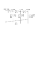
まず、図3の状態において、各カメラ50,60,70の電源投入時の初期化設定において、各カメラ50,60,70のID番号がクリアされ、予めポート3aおよびポート9aを短絡するようにスイッチ11が切り換えられる。
【0033】
そして、HOST PC40のポート4aから直接接続されているカメラ50に対して‘送信機器ID番号“00”cascade “ON”’ なるカスケード接続コマンドを出力する。
【0034】
カメラ50において、上記カスケード接続コマンドが入力されると、自身の機器のID番号を0+1=1すなわちID番号を‘01’にセットし、バッファメモリに記憶させる。(図3および図5において、カメラ50は直接HOST PC40に接続されるものであり、かつ接続の末端ではないのでHOST PC40にAckコマンドは出力していないが、設定されたID番号を付加してHOST PC40にAckコマンドを出力してもよい)。Ack出力コマンド後、出力ポート9cから制御信号を出力することにより、スイッチ11を切り換えてポート3aとポート5aとを接続させる。続いて、‘送信元機器ID番号“01”cascade “ON”’ というカスケード接続コマンドが9aを介して5aからカメラ60に対して出力される。その後、出力ポート9cから制御信号をカメラ60へ出力することにより、スイッチ11を切り換えてポート3aとポート9aとを接続させる。その後、カメラ60からAckコマンドが入力された場合、カメラ50における動作処理が終了される。
【0035】
次に、カメラ60において、カメラ50から出力されたカスケード接続コマンドが入力されると、自身の機器のID番号を1+1=2すなわちID番号を‘02’にセットし、バッファメモリに記憶させる。そして、設定されたID番号を付加してカメラ50にAckコマンドを出力する。Ackコマンド出力後、出力ポート9cから制御信号を出力することにより、スイッチ11を切り換えてポート3aとポート5aとを接続させる。続いて、‘送信元機器ID番号“02”cascade “ON”’ というカスケード接続コマンドが9aを介して5aからカメラ70に対して出力される。その後、出力ポート9cから制御信号を出力することにより、スイッチ11を切り換えてポート3aとポート9aとを接続させる。その後、カメラ70からAckコマンドが入力された場合、カメラ60における動作処理が終了される。
【0036】
次に、カメラ70において、カメラ60から出力されたカスケード接続コマンドが入力されると、自身の機器のID番号を2+1=3すなわちID番号を‘02’にセットし、バッファメモリに記憶させる。そして、設定されたID番号を付加してカメラ60にAckコマンドを出力する。Ackコマンド出力後、出力ポート9cから制御信号を出力することにより、スイッチ11を切り換えてポート3aとポート5aとを接続させる。続いて、‘送信元機器ID番号“03”cascade “ON”’ というカスケード接続コマンドが5aから9aを介して出力される。図4に示されるように、カメラ70は、接続の末端であるので当然のことながらAckコマンドは入力されない。カメラ70は、所定時間(例えば1秒)経過後、Ackコマンドが入力されなかったのを確認し、自身のカメラが末端の接続である旨の情報をステータス情報に付加し、HOST PC40に対してAck信号を出力することになる。
【0037】
HOST PC40は、カスケード接続コマンドを送信してから最大5秒後までにカメラ70から出力されたID“03”のAckを受信し、3台のカメラが接続されていることを把握する。
【0038】
このようにHOST PC40側で接続されているカメラの台数を把握した後、後述する処理に従って接続されているカメラの制御を実行することができる。なお、上述した実施の形態では接続システムの起動時にカスケード接続コマンドを出力したが、周期的にカスケード接続コマンドをHOST PC40側から出力してもよい。このような処理の場合、カメラの接続状態が変更したとしても現在の接続状態を正しく把握することができる。
【0039】
ここで、図6を用い、カスケード接続コマンドを出力することによってHOST PC40側でカメラの接続状態を認識したあと、接続されているカメラに対する制御コマンドを出力したときの動作処理例を説明する(図6は、HOST PC40からカメラ60に対して制御コマンドを発信したときの動作処理例である)。
【0040】
なお、HOST PC40側から制御コマンドが接続されているカメラに対して出力される場合、既にカスケード接続コマンドが出力された後であるので、各カメラのスイッチ11は、制御コマンドが入力されたときに対応可能なように図4に示すようにすでに切り換えられている。すなわち、末端に接続されているカメラ70のみポート3aと9aとが短絡するようにスイッチ11が切り換えられ、後段にも前段にも機器が接続されているカメラ50,60においてはポート3aと5bとが短絡するようにスイッチ11が切り換えられている。
【0041】
まず、HOST PC40から制御コマンドがカメラ50に出力される。制御コマンドは、図2に示すように、ヘッダー,送信先機器ID番号(図6の場合、カメラ60に対する制御コマンドであるので“02”である),コマンド(パン,チルト命令など),パラメーター(コマンドに対する駆動量),ターミネーターなどのパケット構成からなる。
【0042】
カメラ50において、ポート3bを介して9bに制御コマンドが入力されると、カメラ50のCPU9は、入力された制御コマンドの送信先ID番号を確認する。カメラ50のID番号は“01”であるので自身に対する制御コマンドではないと判断し、カメラ60に制御コマンドを転送する。
【0043】
カメラ60において、ポート3bを介して9bに制御コマンドが入力されると、カメラ60のCPU9は、入力された制御コマンドの送信先ID番号を確認する。カメラ60のID番号は“02”であるので自身に対する制御コマンドであると判断し、その制御コマンドに基づいてカメラ60の制御を行なう。カメラ制御終了後、ポート9aを介して5aより送信先のID番号(HOST PC40のID番号“00”)および送信元のID番号(カメラ60のID番号“02”)が付加されたAckコマンドが出力される。
【0044】
カメラ70において、ポート3bを介して9bにAckコマンドが入力されると、カメラ60のCPU9は、入力されたAckコマンドの送信先ID番号を確認する。カメラ50のID番号は“03”であるので自身に対する制御コマンドではないと判断し、HOST PC40にカメラ60にAckコマンドを転送する。
【0045】
HOST PC40は、Ackコマンドをポート4bより受け取り、制御が行なわれたことを確認し、動作を終了させる。
【0046】
図6では、カメラ60に対する制御命令がHOST PC40から出力されたときのコマンド処理を説明したが、制御コマンドおよびAckコマンドに送信先のID番号にカメラ50,70のID番号を書き込むことによって同様の処理を実行することができる。
【0047】
次に、図7を用い、制御コマンドの送信先機器ID番号に“00”を付加して出力した場合の動作処理例を説明する。
【0048】
送信先機器ID番号に“00”が付加されて制御コマンドがHOST PC40から出力されると、各カメラにおいて、このID番号“00”を認識すると各カメラにおいてこの制御コマンドに基づく制御が実行される。そして、末端のカメラ70の制御実行終了後、カメラ70からAckコマンドがHOST PC40に出力され、処理が終了する。
【0049】
すなわち、制御コマンドの送信先機器ID番号に“00”が付加されて出力された場合、接続されている全ての電子機器においてその制御コマンドに基づく制御が実行されることとなる。
【0050】
なお上述した実施の形態では、各カメラ50,60,70に入出力端子3,5およびCPU9が設置される構成となっているが、入出力端子3,5およびCPU9を接続装置として各カメラ50,60,70とは別体に設けてもよい。
【0051】
以上説明したように、上述の実施形態によれば、HOST PC40からシリアルに接続されたカメラを必要最低限の信号線を用いて制御することができる。
【0052】
本発明は、一例として、前述した実施形態の機能を実現するソフトウェアのプログラムコードを記録した記録媒体を、システムあるいは装置に供給し、そのシステムあるいは装置のコンピュータ(またはCPUやMPU)が記憶媒体に格納されたプログラムコードを読み出し実行することによって達成できる。
【0053】
この場合、記憶媒体から読み出されたプログラムコード自体が前述した実施形態の機能を実現することになり、そのプログラムコードを記憶した記憶媒体は本発明を構成することになる。
【0054】
プログラムコードを供給するための記憶媒体としては、例えば、フロッピーディスク、ハードディスク、光ディスク、光磁気ディスク、CD−ROM、CD−R、磁気テープ、不揮発性のメモリカード、ROMなどを用いることができる。
【0055】
また、コンピュータが読み出したプログラムコードを実行することにより、前述した実施形態の機能が実現されるだけでなく、そのプログラムコードの指示に基づき、コンピュータ上で稼動しているOS(オペレーティングシステム)などが実際の処理の一部または全部を行い、その処理によって前述した実施形態の機能が実現される場合も含まれる。
【0056】
さらに、記憶媒体から読み出されたプログラムコードが、コンピュータに挿入された機能拡張ボードやコンピュータに接続された機能拡張ユニットに備わるメモリに書き込まれた後、そのプログラムコードの指示にもとづき、その機能拡張ボードや機能拡張ユニットに備わるCPUなどが実際の処理の一部または全部を行い、その処理によって前述した実施形態の機能が実現される。
【0057】
本発明を上記記憶媒体に適用する場合、その記憶媒体には、先に説明したフローチャートに対応するプログラムコードを格納することになるが、簡単に説明すると、本実施の形態の電子機器接続システムに不可欠なモジュールを、記憶媒体に格納することになる。
【0058】
【発明の効果】
以上説明したように本発明によれば、最低限の信号線を用いてシリアルに接続された複数の電子機器の制御を統括的に実行することできる。
【図面の簡単な説明】
【図1】本発明の実施の形態における電子機器の接続構成の一例を示す図。
【図2】本発明の実施の形態における電子機器間を送受信されるコマンドの一例を示す図。
【図3】本発明の実施の形態における電子機器の接続構成における制御方法の一例を説明する図。
【図4】本発明の実施の形態における電子機器の接続構成における制御方法の一例を説明する図。
【図5】本発明の実施の形態における電子機器の接続構成におけるカスケード接続コマンドの送受信の一例を示す図。
【図6】本発明の実施の形態における電子機器の接続構成における制御コマンドの送受信の一例を示す図。
【図7】本発明の実施の形態における電子機器の接続構成における制御コマンドの送受信の一例を示す図。
【図8】本発明の実施の形態における電子機器の動作処理フローチャートを示す図。
【図9】本発明の実施の形態におけるHOST PCの動作処理フローチャートを示す図。
【符号の説明】
3,4,5 入出力端子
40 HOST PC
50,60,70 カメラ
9 CPU[0001]
BACKGROUND OF THE INVENTION
The present invention relates to a method for connecting electronic devices that collectively control a plurality of electronic devices such as cameras.
[0002]
[Prior art]
Conventionally, a technique for controlling an electronic device such as a camera from a personal computer (PC) using a standard such as RS-232C is known.
[0003]
When such RS-232C standard is used, it is impossible to control a plurality of electronic devices unless the PC has a plurality of connectors.
[0004]
In order to solve such a problem, Japanese Patent No. 2867649 discloses a method of controlling a plurality of electronic devices connected in series.
[0005]
[Problems to be solved by the invention]
However, in Japanese Patent No. 2867649, in addition to a signal line for transmitting and receiving a control signal for an electronic device, a terminal “3f” for determining whether or not another connection device is connected in the subsequent stage is required. In order to solve such a problem, an object of the present invention is to provide a method for controlling an electronic device that can be controlled by serially connecting a plurality of electronic devices without increasing the number of signal lines.
[0006]
[Means for Solving the Problems]
In order to achieve the above object, the electronic device of the present invention is serially connected from a computer, and can transmit / receive a control command, a first control signal, and a second control signal to / from each other. An electronic device controlled in an integrated manner, comprising: a first input / output unit connected to a preceding electronic device; a second input / output unit connected to a subsequent electronic device; In response to the input of the first control signal via the first input / output means, a new first control signal is output to the electronic device connected to the subsequent stage via the second input / output means. When it is determined whether the second control signal is input with respect to the output of the first control signal to the electronic device connected to the subsequent stage, and it is determined that the second control signal is not input The electronic device is connected to the end Includes a processing means for outputting to said computer via said first input-output means Rukoto, is characterized in that the first control signal from said computer for every predetermined period is output.
Further, the computer according to the present invention is a computer that generally controls the electronic device by serially connecting the electronic device and transmitting / receiving a control command and a predetermined control signal to / from the electronic device. A predetermined control signal to which the computer ID number is added is output, whether or not a command corresponding to the predetermined control signal is input, and when it is confirmed that the command is input, And processing means for recognizing the connection state of the electronic device, and outputting the predetermined control signal at predetermined intervals.
The electronic device connection method of the present invention is serially connected from a computer, and can transmit and receive a control command, a first control signal, and a second control signal to each other. A method of connecting an electronic device to be controlled, wherein the first control signal is output from the computer, and the electronic device responds to the input of the first control signal from the computer or the preceding electronic device. The ID number of the electronic device is set based on the ID number of the first control signal, the first control signal is newly output to the electronic device to be connected to the subsequent stage, and should be connected to the subsequent stage. It is determined whether or not the second control signal is input with respect to the output of the first control signal to the electronic device, and when the second control signal is not input, And outputs the ID number of the serial electronic apparatus, by outputting said electronic device is a terminal connection to the computer, is characterized in that to recognize the connection state of the electronic device to the computer.
[0013]
DETAILED DESCRIPTION OF THE INVENTION
Hereinafter, embodiments of the present invention will be described with reference to the accompanying drawings.
[0014]
FIG. 1 is a diagram illustrating an example of a system that controls an electronic device serially connected by RS-232C from a personal computer (PC) according to the present embodiment. In this embodiment, a camera capable of panning and tilting control is exemplified as an electronic device.
[0015]
The
[0016]
The
[0017]
The
[0018]
The HOST PC 40 has an input /
[0019]
The
[0020]
FIG. 8 is an operation process flowchart of the CPU 9 when a cascade connection command for the HOST PC 40 to recognize the connection state of the camera is input to the camera serially connected by the RS-232C. The cascade connection command is used to set an ID for the camera to which the HOST PC 40 is connected and to recognize the set camera ID.
[0021]
In S101, it is determined whether or not a cascade connection command has been received via the
[0022]
In S102, the received cascade connection command is confirmed, and “ID number + 1 of the transmission source device (camera or HOST PC 40) +1” is set as its own ID number and stored in a buffer memory (not shown).
[0023]
In S103, it is confirmed whether or not the
[0024]
In S105, the Ack command is output from the
[0025]
After outputting the Ack command, in step S106, a control signal is output from the
[0026]
In S109, it is confirmed whether or not an Ack command having a transmission source device ID number of own ID number + 1 is input from 9d via 5b. When the Ack command is input, the process proceeds to S110, and a control signal is output from the
[0027]
If the Ack command has not been input, it is determined in S111 whether a predetermined time has elapsed. If the predetermined time has not elapsed, the process returns to S109 to wait for input of an Ack command. On the other hand, if the Ack command is not input even after the predetermined time has elapsed, it is determined that the camera is connected to the end, and the process proceeds to S112. In S110, information indicating that the device is the terminal connection is added to the status information, and an Ack signal is output to the
[0028]
FIG. 9 is an operational process flowchart of the
[0029]
First, in S201, a cascade connection command of 'transmitting device ID number “00” cascade “ON” ”is output. In step S202, when the Ack signal of the camera connected to the terminal is received, the ID number and status information of the camera are acquired, and then the process ends. If the Ack signal of the camera connected to the end is not received, the process proceeds to S204. In S204, it is determined whether or not a predetermined time has elapsed since the cascade connection command was output. If the predetermined time has not elapsed, the process returns to S202. If the predetermined time has elapsed, an error message is output in the
[0030]
In this way, when controlling the camera, the connection state of the camera can be grasped on the
[0031]
Here, using FIG. 3 to FIG. 5, an operation process when a cascade connection signal is output from the
[0032]
First, in the state of FIG. 3, in the initialization setting when the
[0033]
Then, a cascade connection command of 'transmitting device ID number “00” cascade “ON” ”is output to the
[0034]
In the
[0035]
Next, when the cascade connection command output from the
[0036]
Next, when the cascade connection command output from the
[0037]
The
[0038]
Thus, after grasping the number of cameras connected on the
[0039]
Here, FIG. 6 is used to explain an example of operation processing when a control command for a connected camera is output after the connection state of the camera is recognized on the
[0040]
Note that when the control command is output from the
[0041]
First, a control command is output from the
[0042]
In the
[0043]
In the
[0044]
In the
[0045]
The
[0046]
In FIG. 6, the command processing when the control command for the
[0047]
Next, an example of operation processing when “00” is added to the transmission destination device ID number of the control command and output will be described with reference to FIG.
[0048]
When “00” is added to the transmission destination device ID number and a control command is output from the
[0049]
That is, when “00” is added to the transmission destination device ID number of the control command and output, control based on the control command is executed in all connected electronic devices.
[0050]
In the above-described embodiment, the input /
[0051]
As described above, according to the above-described embodiment, it is possible to control a camera serially connected from the
[0052]
As an example, the present invention supplies a recording medium that records software program codes for realizing the functions of the above-described embodiments to a system or apparatus, and the computer (or CPU or MPU) of the system or apparatus stores the recording medium. This can be achieved by reading and executing the stored program code.
[0053]
In this case, the program code itself read from the storage medium realizes the functions of the above-described embodiments, and the storage medium storing the program code constitutes the present invention.
[0054]
As a storage medium for supplying the program code, for example, a floppy disk, a hard disk, an optical disk, a magneto-optical disk, a CD-ROM, a CD-R, a magnetic tape, a nonvolatile memory card, a ROM, or the like can be used.
[0055]
Further, by executing the program code read by the computer, not only the functions of the above-described embodiments are realized, but also an OS (operating system) operating on the computer based on the instruction of the program code. A case where part or all of the actual processing is performed and the functions of the above-described embodiments are realized by the processing is also included.
[0056]
Further, after the program code read from the storage medium is written to the memory provided in the function expansion board inserted into the computer or the function expansion unit connected to the computer, the function expansion is performed based on the instruction of the program code. The CPU or the like provided in the board or the function expansion unit performs part or all of the actual processing, and the functions of the above-described embodiments are realized by the processing.
[0057]
When the present invention is applied to the above-described storage medium, the storage medium stores program codes corresponding to the flowcharts described above, but briefly, the electronic apparatus connection system of the present embodiment will be described. Indispensable modules are stored in the storage medium.
[0058]
【The invention's effect】
As described above, according to the present invention, it is possible to comprehensively execute control of a plurality of electronic devices connected serially using a minimum number of signal lines.
[Brief description of the drawings]
FIG. 1 illustrates an example of a connection configuration of an electronic device according to an embodiment of the present invention.
FIG. 2 is a diagram showing an example of a command transmitted / received between electronic devices in the embodiment of the present invention.
FIG. 3 is a diagram illustrating an example of a control method in a connection configuration of an electronic device according to an embodiment of the present invention.
FIG. 4 is a diagram illustrating an example of a control method in a connection configuration of an electronic device according to an embodiment of the present invention.
FIG. 5 is a diagram showing an example of transmission / reception of a cascade connection command in the connection configuration of the electronic device according to the embodiment of the present invention.
FIG. 6 is a diagram showing an example of transmission / reception of control commands in the connection configuration of the electronic device according to the embodiment of the present invention.
FIG. 7 is a diagram showing an example of transmission / reception of control commands in the connection configuration of the electronic device according to the embodiment of the present invention.
FIG. 8 is a diagram showing an operation processing flowchart of the electronic device in the embodiment of the present invention.
FIG. 9 is a diagram showing an operation processing flowchart of the HOST PC in the embodiment of the present invention.
[Explanation of symbols]
3, 4, 5 I /
50, 60, 70 Camera 9 CPU
Claims (3)
Priority Applications (4)
| Application Number | Priority Date | Filing Date | Title |
|---|---|---|---|
| JP2000222193A JP4467727B2 (en) | 2000-07-24 | 2000-07-24 | Electronic device connection method, electronic device, and storage medium storing operation processing program thereof |
| US09/907,673 US6834321B2 (en) | 2000-07-24 | 2001-07-19 | Communication method of a serially connected electronic apparatus |
| DE60118668T DE60118668T2 (en) | 2000-07-24 | 2001-07-20 | Communication method of an electronic device |
| EP01306273A EP1176484B1 (en) | 2000-07-24 | 2001-07-20 | Communication method of an electronic apparatus |
Applications Claiming Priority (1)
| Application Number | Priority Date | Filing Date | Title |
|---|---|---|---|
| JP2000222193A JP4467727B2 (en) | 2000-07-24 | 2000-07-24 | Electronic device connection method, electronic device, and storage medium storing operation processing program thereof |
Related Child Applications (1)
| Application Number | Title | Priority Date | Filing Date |
|---|---|---|---|
| JP2009272568A Division JP5059086B2 (en) | 2009-11-30 | 2009-11-30 | Electronic device and method of connecting electronic device |
Publications (3)
| Publication Number | Publication Date |
|---|---|
| JP2002044089A JP2002044089A (en) | 2002-02-08 |
| JP2002044089A5 JP2002044089A5 (en) | 2007-09-20 |
| JP4467727B2 true JP4467727B2 (en) | 2010-05-26 |
Family
ID=18716466
Family Applications (1)
| Application Number | Title | Priority Date | Filing Date |
|---|---|---|---|
| JP2000222193A Expired - Fee Related JP4467727B2 (en) | 2000-07-24 | 2000-07-24 | Electronic device connection method, electronic device, and storage medium storing operation processing program thereof |
Country Status (4)
| Country | Link |
|---|---|
| US (1) | US6834321B2 (en) |
| EP (1) | EP1176484B1 (en) |
| JP (1) | JP4467727B2 (en) |
| DE (1) | DE60118668T2 (en) |
Families Citing this family (23)
| Publication number | Priority date | Publication date | Assignee | Title |
|---|---|---|---|---|
| US7203728B2 (en) * | 1993-01-26 | 2007-04-10 | Logic Controls, Inc. | Point-of-sale system and distributed computer network for same |
| US6928501B2 (en) * | 2001-10-15 | 2005-08-09 | Silicon Laboratories, Inc. | Serial device daisy chaining method and apparatus |
| CN1708949A (en) * | 2002-10-25 | 2005-12-14 | 西铁城时计株式会社 | Electronic device system |
| US20050050063A1 (en) * | 2003-08-26 | 2005-03-03 | Haas William Robert | Data management system and method with multi-port processor |
| US7984195B2 (en) * | 2006-07-07 | 2011-07-19 | Logic Controls, Inc. | Hybrid industrial networked computer system |
| JP2006133996A (en) * | 2004-11-04 | 2006-05-25 | Canon Inc | System and method for serial communication |
| KR100643380B1 (en) * | 2004-11-17 | 2006-11-10 | 삼성전자주식회사 | Communication apparatus |
| EP1667374B1 (en) | 2004-12-03 | 2011-09-21 | Sony Corporation | Apparatus connection interface, apparatus control system and method of controlling apparatus control system |
| JP2006201964A (en) * | 2005-01-19 | 2006-08-03 | Fuji Xerox Co Ltd | Computer system and image formation apparatus |
| FR2901211B1 (en) * | 2006-05-17 | 2008-08-22 | Valeo Systemes Thermiques | AUTOMATIC ADDRESSING SYSTEM FOR ACTUATORS IN A MOTOR VEHICLE. |
| TW200922377A (en) * | 2007-11-14 | 2009-05-16 | Arc Solid State Lighting Corp | Light driving device and light system thereof |
| TW201012130A (en) * | 2008-09-08 | 2010-03-16 | Brainchild Electronic Co Ltd | Remote communication method of a network and system thereof |
| US8296488B2 (en) | 2009-04-27 | 2012-10-23 | Abl Ip Holding Llc | Automatic self-addressing method for wired network nodes |
| JP5879706B2 (en) * | 2011-03-15 | 2016-03-08 | オムロン株式会社 | Control system, operation terminal and program |
| US8705967B2 (en) * | 2011-07-28 | 2014-04-22 | Motorola Solutions, Inc. | Serially-distributed access points in a communication network |
| US10311010B2 (en) * | 2011-10-05 | 2019-06-04 | Analog Devices, Inc. | Two-wire communication systems and applications |
| US10649948B2 (en) * | 2011-10-05 | 2020-05-12 | Analog Devices, Inc. | Two-wire communication systems and applications |
| JP5930767B2 (en) | 2012-02-23 | 2016-06-08 | キヤノン株式会社 | Electronic device, communication control method |
| JP5968119B2 (en) * | 2012-06-27 | 2016-08-10 | キヤノン株式会社 | Communication system with cascade connection |
| JP5661702B2 (en) | 2012-08-23 | 2015-01-28 | キヤノン株式会社 | Electronic system and communication control method |
| KR101552255B1 (en) * | 2014-03-20 | 2015-09-09 | 김관석 | Block toy |
| JP2016096493A (en) * | 2014-11-17 | 2016-05-26 | 富士ゼロックス株式会社 | Communication system and image forming device |
| CN114554037B (en) * | 2020-11-26 | 2023-04-18 | 华为技术有限公司 | Data transmission method and electronic equipment |
Family Cites Families (12)
| Publication number | Priority date | Publication date | Assignee | Title |
|---|---|---|---|---|
| US4443866A (en) * | 1975-08-27 | 1984-04-17 | Corning Glass Works | Automatic device selection circuit |
| FR2691558B1 (en) * | 1992-05-21 | 1997-08-01 | Sextant Avionique | DEVICE FOR MANAGING THE PRIORITY OF ACCESS TO COMMON RESOURCES, OF FUNCTIONAL MODULES DISTRIBUTED IN A PLURALITY OF LOCAL UNITS BY FORMING IN EACH OF THESE, A LOCAL "DAISY CHAIN". |
| US6272529B1 (en) * | 1993-01-26 | 2001-08-07 | Logic Controls, Inc. | Point-of-sale system and distributed computer network for same |
| JP3224326B2 (en) * | 1994-06-24 | 2001-10-29 | 富士通株式会社 | Disk device and disk subsystem |
| JPH08106413A (en) * | 1994-10-06 | 1996-04-23 | Fujitsu Ltd | Data processor, data transfer method and memory device |
| DE19513747B4 (en) | 1995-04-11 | 2004-12-09 | Trieschmann, Olaf, Dr. | Method and device for controlling systems using a control computer |
| JPH09179810A (en) * | 1995-12-25 | 1997-07-11 | Matsushita Electric Works Ltd | Unit selecting device |
| DE19624528B4 (en) * | 1996-06-20 | 2009-05-20 | Robert Bosch Gmbh | Method for controlling information transmission between components and component for carrying out the method |
| EP0854609A3 (en) * | 1997-01-21 | 1999-12-22 | Nittan Company, Limited | Transmitting system |
| US5933656A (en) * | 1997-06-18 | 1999-08-03 | Raytheon Company | System for interfacing host computer to multiple peripheral devices using daisy-chainable bus and federated computational input/output circuit card assemblies |
| DE19740306A1 (en) | 1997-09-13 | 1999-03-18 | Dornier Gmbh Lindauer | Loom control |
| JP2000067352A (en) | 1998-06-16 | 2000-03-03 | Pittway Corp | Method and device for address allocation |
-
2000
- 2000-07-24 JP JP2000222193A patent/JP4467727B2/en not_active Expired - Fee Related
-
2001
- 2001-07-19 US US09/907,673 patent/US6834321B2/en not_active Expired - Fee Related
- 2001-07-20 EP EP01306273A patent/EP1176484B1/en not_active Expired - Lifetime
- 2001-07-20 DE DE60118668T patent/DE60118668T2/en not_active Expired - Lifetime
Also Published As
| Publication number | Publication date |
|---|---|
| US6834321B2 (en) | 2004-12-21 |
| US20020016875A1 (en) | 2002-02-07 |
| JP2002044089A (en) | 2002-02-08 |
| EP1176484A3 (en) | 2003-11-12 |
| DE60118668D1 (en) | 2006-05-24 |
| EP1176484A2 (en) | 2002-01-30 |
| DE60118668T2 (en) | 2006-10-05 |
| EP1176484B1 (en) | 2006-04-12 |
Similar Documents
| Publication | Publication Date | Title |
|---|---|---|
| JP4467727B2 (en) | Electronic device connection method, electronic device, and storage medium storing operation processing program thereof | |
| US20010013540A1 (en) | An ic card reading/writing apparatus and an ic card system | |
| CN101673202A (en) | Program writing method and system, pre-writing device and writing device | |
| JP3028815B2 (en) | Transmission method of portable electronic device and portable electronic device | |
| JPH0824320B2 (en) | Method and device for buffer chaining in communication control device | |
| KR100919159B1 (en) | Multimedia card interface method, computer program product and apparatus | |
| EP0886410A2 (en) | Data communication method, data communication apparatus, and data communication program recording medium | |
| US6977901B2 (en) | Packet transmission/reception processor | |
| US6058440A (en) | Programmable and adaptive resource allocation device and resource use recorder | |
| JP5059086B2 (en) | Electronic device and method of connecting electronic device | |
| JPH01135150A (en) | Node address setting system for network | |
| CN100517377C (en) | Multifunctional IC card and control method thereof | |
| JPWO2005066745A1 (en) | Bus share adapter | |
| JP2748253B2 (en) | IC card information processing system | |
| EP1179907A2 (en) | Data communication apparatus and method with error correction mode | |
| US20030093642A1 (en) | Systems and methods for controlling communication with nonvolatile memory devices | |
| CN100527113C (en) | Multimedia card interface method, computer program product and apparatus | |
| JP2006127128A (en) | Slave apparatus of information processing system, operation control program for slave apparatus and operation control method for slave apparatus | |
| JPH03276383A (en) | Communication system for ic card | |
| JP2006031235A (en) | Information processor, external device, host device, and communication method | |
| CN115243127A (en) | Stereo set firmware upgrading circuit and electronic equipment | |
| JPH05292146A (en) | Discrimination method for communication protocol | |
| JP2004252499A (en) | Reader/writer and communication system | |
| JPH05292141A (en) | Communication connector | |
| CN115599721A (en) | Port switching method, system, computing device and chip |
Legal Events
| Date | Code | Title | Description |
|---|---|---|---|
| A521 | Request for written amendment filed |
Free format text: JAPANESE INTERMEDIATE CODE: A523 Effective date: 20070724 |
|
| A621 | Written request for application examination |
Free format text: JAPANESE INTERMEDIATE CODE: A621 Effective date: 20070724 |
|
| A977 | Report on retrieval |
Free format text: JAPANESE INTERMEDIATE CODE: A971007 Effective date: 20090910 |
|
| A131 | Notification of reasons for refusal |
Free format text: JAPANESE INTERMEDIATE CODE: A131 Effective date: 20090929 |
|
| A521 | Request for written amendment filed |
Free format text: JAPANESE INTERMEDIATE CODE: A523 Effective date: 20091130 |
|
| RD04 | Notification of resignation of power of attorney |
Free format text: JAPANESE INTERMEDIATE CODE: A7424 Effective date: 20100201 |
|
| TRDD | Decision of grant or rejection written | ||
| A01 | Written decision to grant a patent or to grant a registration (utility model) |
Free format text: JAPANESE INTERMEDIATE CODE: A01 Effective date: 20100223 |
|
| A01 | Written decision to grant a patent or to grant a registration (utility model) |
Free format text: JAPANESE INTERMEDIATE CODE: A01 |
|
| A61 | First payment of annual fees (during grant procedure) |
Free format text: JAPANESE INTERMEDIATE CODE: A61 Effective date: 20100224 |
|
| R150 | Certificate of patent or registration of utility model |
Free format text: JAPANESE INTERMEDIATE CODE: R150 |
|
| FPAY | Renewal fee payment (event date is renewal date of database) |
Free format text: PAYMENT UNTIL: 20130305 Year of fee payment: 3 |
|
| FPAY | Renewal fee payment (event date is renewal date of database) |
Free format text: PAYMENT UNTIL: 20140305 Year of fee payment: 4 |
|
| LAPS | Cancellation because of no payment of annual fees |