JP4454837B2 - Image processing device - Google Patents
Image processing device Download PDFInfo
- Publication number
- JP4454837B2 JP4454837B2 JP2000374233A JP2000374233A JP4454837B2 JP 4454837 B2 JP4454837 B2 JP 4454837B2 JP 2000374233 A JP2000374233 A JP 2000374233A JP 2000374233 A JP2000374233 A JP 2000374233A JP 4454837 B2 JP4454837 B2 JP 4454837B2
- Authority
- JP
- Japan
- Prior art keywords
- pixels
- memory
- circuit
- image signal
- image
- Prior art date
- Legal status (The legal status is an assumption and is not a legal conclusion. Google has not performed a legal analysis and makes no representation as to the accuracy of the status listed.)
- Expired - Fee Related
Links
Images


Classifications
-
- H—ELECTRICITY
- H04—ELECTRIC COMMUNICATION TECHNIQUE
- H04N—PICTORIAL COMMUNICATION, e.g. TELEVISION
- H04N5/00—Details of television systems
- H04N5/76—Television signal recording
- H04N5/765—Interface circuits between an apparatus for recording and another apparatus
- H04N5/77—Interface circuits between an apparatus for recording and another apparatus between a recording apparatus and a television camera
- H04N5/772—Interface circuits between an apparatus for recording and another apparatus between a recording apparatus and a television camera the recording apparatus and the television camera being placed in the same enclosure
-
- H—ELECTRICITY
- H04—ELECTRIC COMMUNICATION TECHNIQUE
- H04N—PICTORIAL COMMUNICATION, e.g. TELEVISION
- H04N23/00—Cameras or camera modules comprising electronic image sensors; Control thereof
-
- H—ELECTRICITY
- H04—ELECTRIC COMMUNICATION TECHNIQUE
- H04N—PICTORIAL COMMUNICATION, e.g. TELEVISION
- H04N23/00—Cameras or camera modules comprising electronic image sensors; Control thereof
- H04N23/80—Camera processing pipelines; Components thereof
- H04N23/84—Camera processing pipelines; Components thereof for processing colour signals
-
- H—ELECTRICITY
- H04—ELECTRIC COMMUNICATION TECHNIQUE
- H04N—PICTORIAL COMMUNICATION, e.g. TELEVISION
- H04N25/00—Circuitry of solid-state image sensors [SSIS]; Control thereof
- H04N25/10—Circuitry of solid-state image sensors [SSIS]; Control thereof for transforming different wavelengths into image signals
- H04N25/11—Arrangement of colour filter arrays [CFA]; Filter mosaics
- H04N25/13—Arrangement of colour filter arrays [CFA]; Filter mosaics characterised by the spectral characteristics of the filter elements
- H04N25/135—Arrangement of colour filter arrays [CFA]; Filter mosaics characterised by the spectral characteristics of the filter elements based on four or more different wavelength filter elements
- H04N25/136—Arrangement of colour filter arrays [CFA]; Filter mosaics characterised by the spectral characteristics of the filter elements based on four or more different wavelength filter elements using complementary colours
-
- H—ELECTRICITY
- H04—ELECTRIC COMMUNICATION TECHNIQUE
- H04N—PICTORIAL COMMUNICATION, e.g. TELEVISION
- H04N5/00—Details of television systems
- H04N5/76—Television signal recording
- H04N5/907—Television signal recording using static stores, e.g. storage tubes or semiconductor memories
-
- H—ELECTRICITY
- H04—ELECTRIC COMMUNICATION TECHNIQUE
- H04N—PICTORIAL COMMUNICATION, e.g. TELEVISION
- H04N9/00—Details of colour television systems
- H04N9/79—Processing of colour television signals in connection with recording
- H04N9/7921—Processing of colour television signals in connection with recording for more than one processing mode
Landscapes
- Engineering & Computer Science (AREA)
- Multimedia (AREA)
- Signal Processing (AREA)
- Physics & Mathematics (AREA)
- Spectroscopy & Molecular Physics (AREA)
- Television Signal Processing For Recording (AREA)
- Signal Processing For Digital Recording And Reproducing (AREA)
Description
【0001】
【発明の属する技術分野】
本発明は画像処理装置関し、特に、メモリを用いて異なる画素数の画像信号を処理する装置に関する。
【0002】
【従来の技術】
従来、ビデオカメラにより撮影された画像信号をデジタル信号として磁気テープに記録するビデオカメラ一体型デジタルVTRが知られている。また、近年では、メモリカードスロットを備え、動画像データについては従来通り磁気テープに記録し、メモリカードに対して静止画像を記録可能なデジタルVTRも開発されている。
【0003】
【発明が解決しようとする課題】
一方、近年の半導体技術の向上により、CCDの画素数が飛躍的に増加しており、前記のデジタルVTRにおいても従来のものより多画素のCCDを用いて静止画像を撮影、記録することが考えられる。
【0004】
しかし、従来のデジタルでは、動画像データと静止画像データとが同一の画素数の信号であることを前提として設計されている。そのため、このようにCCDの画素数が増加し、その結果、静止画像データの画素数が増加した場合に、容易に対応することができない。
【0005】
また、近年では、回路特性の安定化や消費電力の削減のため、メモリを含めた動画像処理回路、静止画像処理回路などの各回路を同一の集積回路上に配置するのが一般的である。
【0006】
しかし、画像信号の画素数が増加した場合、特に静止画処理については画像データの画素数に対応した記憶容量のメモリが必要となるが、静止画処理用のメモリまでもが同一の集積回路上に配置されている場合、メモリ回路のみを増設、あるいはより大容量のものに交換することができない。そのため、画像信号の画素数が増加する度に新たに集積回路を設計しなおす必要があり、大変な労力、コストがかかっていた。
【0007】
本発明は、前述の如き問題を解決することを目的とする。
【0008】
本発明の他の目的は、画像信号の画素数が変更した場合であっても容易に動画像、静止画像データの処理を可能とする処にある。
【0009】
本発明の更に他の目的は、画像信号の画素数が変更された場合であっても集積回路の設計を変更することなく容易に静止画像データの処理を可能とする処にある。
【0010】
【課題を解決するための手段】
本発明は、所定の記録フォーマットに対応した所定の画素数よりも多い第1の画素数の画像信号を出力する撮像手段と、前記撮像手段から出力された前記第1の画素数の画像信号を前記所定の画素数の画像信号に変換する変換手段と、前記所定の画素数に対応した記憶容量を持ち、前記変換手段から出力される前記所定の画素数の画像信号を記憶する第1のメモリと、前記第1の画素数に対応した記憶容量を持ち、前記撮像手段より出力された前記第1の画素数の画像信号を記憶する第2のメモリと、前記第2のメモリのアドレスを発生し、前記撮像手段より出力された前記第1の画素数の画像信号を前記第2のメモリに書き込むと共に前記第2のメモリより前記第1の画素数の画像信号を読み出すメモリインターフェイスと、前記第1のメモリに記憶されている前記所定の画素数の画像信号を、前記所定の記録フォーマットに従って動画像データとして記録媒体に記録する記録手段と、前記第2のメモリから読み出された前記第1の画素数の画像信号を静止画像データとして出力する静止画処理手段とを備え、前記変換手段、前記第1のメモリ、前記メモリインターフェイス及び前記静止画処理手段を同一の集積回路上に配置し、前記撮像手段、前記記録手段及び前記第2のメモリを前記集積回路とは独立した回路として構成した。
【0011】
【発明の実施の形態】
以下、本発明の実施形態について説明する。
【0012】
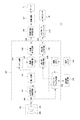
図1は本発明が適用されるカメラ一体型デジタルVTR100の構成を示すブロック図である。本形態のデジタルVTRは、メモリカードを装着するカードスロットを備え、動画像データを磁気テープに記録する動画モードと、静止画像データをメモリカードに記録する静止画モードとを持つ。まず、動画モード時の動作について説明する。
【0013】
図1において、101は撮像回路であり、レンズ、絞り等を含む光学系103と、CCDとその駆動回路やA/D変換器等を含む撮像素子105からなる。図1の装置では、撮像素子として、一般的な補色フィルタを配した単版のCCDを用いており、CCDの画素数は約200万画素、1フレームの有効画素数が水平1600画素×垂直1200画素のUXGAサイズの画像データを出力するものである。本形態では、CCDの色フィルタはシアン(Cy)、イエロー(Y)、グリーン(G)、マゼンタ(Mg)で構成され、図2に示す配列となっている。
【0014】
CCDから画像データを読み出す際、動画モードにおいては、隣接する2ラインの画素を加算して読み出すのが一般的である。撮像回路101は、不図示の制御回路によりその読み出し動作が制御され、操作スイッチ143により動画記録モードに設定されると、以下のように画像信号を読み出す。
【0015】
例えば、図2の配列の場合、1フレームの画像データのうち、第1フィールドの画像信号はNライン+(N+1)ライン、(N+2)ライン+(N+3)ラインの順に読み出し、第2フィールドの画像信号は(N+1)ライン+(N+2)ライン、(N+3)ライン+(N+4)ラインの順に読み出す。
【0016】
撮像回路101から出力されたデジタル画像信号は入力端子109を介してカメラ信号処理回路111に出力される。カメラ信号処理回路111は、入力端子109を介して出力された画像データに対してクランプ処理、ホワイトバランス処理の後色分離処理を行う。更に、輪郭補正処理、γ補正処理の後、マトリクス回路により輝度信号Yと色差信号Cr,Cb信号に変換し、動画モードにおいては、変換された画像信号を縮小回路113に出力する。
【0017】
縮小回路113は、カメラ信号処理回路111から出力された画像信号に対して、LPFにより垂直・水平方向の2次元に帯域制限をかける。そして、この帯域制限された画像信号をITU−R601に準拠したサンプリング構造でサブサンプルすることで、カメラ信号処理回路111から出力される画像信号の1フレームの画素数をテープTに記録する上で規定されたフォーマットに従う所定の画素数、例えば本形態では、図3に示すように水平720画素×垂直480画素となるように変換し、そのサイズを縮小する。
【0018】
縮小回路113により処理された画像信号はメモリ回路115に書き込まれる。メモリ回路115は1フレーム分の前記所定の画素数、例えば720×480画素の画像信号をベースバンドのまま、即ち圧縮・符号化処理していない状態で記憶可能な容量を持つ。
【0019】
メモリ回路115に記憶された画像信号は、その出力するべきタイミングに同期して映像処理回路117により読み出される。映像処理回路117はメモリ回路115から読み出した画像信号に対し、電子ズーム処理やワイプ、フェード等の周知の合成処理や特殊効果処理を施し、映像出力回路119に出力する。映像出力回路119は映像処理回路117からの画像信号に対して水平、垂直同期信号を付加し、基準規格のITU−R601/R656に準拠したデジタル映像信号に変換して出力端子121を介して映像記録処理回路135に出力する。
【0020】
映像記録処理回路135は出力端子121を介して出力されたデジタル画像信号に対して周知のブロック符号化処理を施してその情報量を圧縮する。そして、圧縮符号化された画像データに対して、同期、IDデータの付加、あるいはエラー訂正符号化等の処理を施し、記録データ列を生成して記録回路137に出力する。記録回路137は映像記録処理回路135から出力された記録データ列に対してデジタル変調等の処理を施すと共に、回転ヘッドによりテープT上に多数のトラックを形成して記録する。
【0021】
次に、静止画モードについて説明する。静止画モードとは、操作スイッチ143の静止画記録用シャッタボタンが操作されたことに応じて撮像回路101から出力される画像信号のうちの1フレームを抽出し、静止画像データとしてメモリカードMに記録するモードである。
【0022】
操作スイッチ143の静止画記録スイッチが操作されると、撮像回路101は静止画記録スイッチの操作タイミングに応じた1フレームの画像信号を非加算読み出しにてCCDより読み出し、入力端子109に出力する。
【0023】
即ち、撮像回路101は静止画記録スイッチが操作されていない状態では前述のように加算読み出しにより画像信号を読み出し、不図示のモニタに出力している。従って、ユーザは静止画像の記録待機状態ではこのモニタにより通常の動画像データを確認することができる。そこで、ユーザが静止画記録スイッチを操作すると、撮像回路101はその操作タイミングに応じた1フレームの画像信号のみ非加算読み出しにてCCDより読み出す。
【0024】
例えば、図2に示すフィルタ配列の場合、非加算読み出し時においては、第1フィールドの画像信号はNライン、(N+2)ラインの順に読み出し、第2フィールドの画像信号は(N+1)ライン、(N+3)ラインの順に、隣接ラインの画素が加算されない状態で読み出される。
【0025】
このように入力端子109より入力された1フレームの画像信号は一旦メモリインターフェイス回路123に出力され、静止画メモリ回路141に記憶される。
【0026】
メモリインターフェイス回路123は操作スイッチ143の指示を受けた制御CPU133により制御され、静止画メモリ回路141に対して画像データの書き込み、読み出しを行う回路である。静止画メモリ回路141は撮像回路101のCCDの有効画素数に対応する画素数の1フレームの画像データを縮小することなく記憶可能な容量を持つものである。
【0027】
また、本形態では、静止画メモリ回路125として、汎用のSDRAM(Synchronous Dynamic RAM)を使用している。従って、メモリインターフェイス回路123は静止画メモリ回路125として使用される汎用SDRAMの規格に準拠してカメラ信号処理回路111からの画像データをパケット化し、コマンドを付加して静止画メモリ回路125にアクセスする。更に、メモリインターフェイス回路123にて発生する汎用DRAMアドレスに関しては、メモリの拡張性を考慮し、十分な本数を確保している。また、本形態では、例えば、静止画メモリ回路125として、記憶容量が64Mビット程度以上の汎用のSDRAMを用いることができる。
【0028】
静止画メモリ回路125に書き込まれた1フレームの画像データは、メモリインテーフェイス回路123により順次(ノンインターレース)走査にて読み出され、カメラ信号処理回路111に出力される。
【0029】
カメラ信号処理回路111は動画モードと同様、メモリインターフェイス回路123より出力される画像信号に対し、クランプ処理、ホワイトバランス処理の後色分離処理を行い、更に、輪郭補正処理、γ補正処理の後、マトリクス回路により輝度信号Yと色差信号Cr,Cb信号に変換する。カメラ信号処理回路111により処理された1フレームの画像信号は再びメモリインターフェイス回路123に出力され、静止画メモリ回路125に記憶される。
【0030】
輝度信号と色差信号に変換されて静止画メモリ141に書き込まれた1フレームの画像信号は、メモリインターフェイス回路123により、静止画処理回路127による処理に適した順序で読み出され、静止画処理回路127に出力される。
【0031】
静止画処理回路127はメモリインターフェイス回路123から出力される画像信号をJPEG規格に従って符号化し、静止画像データとして静止画出力回路129に出力する。静止画出力回路129はメモリカードインターフェイス139にて扱うファイルフォーマットに従う形態に変換し、出力端子131を介してメモリカードインターフェイス139に出力する。メモリカードインターフェイス139はメモリカードM上の書き込みアドレスを指定し、出力端子131から出力された1フレームの符号化された静止画像データを一つのファイルとしてメモリカードMに記録する。メモリカードMはVTR100に設けられたメモリカードスロットを介してVTR100本体に着脱可能に構成される。
【0032】
ここで、図1において、カメラ信号処理回路111、縮小回路113、メモリ回路115、映像処理回路117、映像出力回路119、メモリインターフェイス回路123、静止画処理回路127、静止画出力回路及び、制御CPU133は同一の集積回路107上に構成されている。そして、静止画メモリ回路125はこれら集積回路107とは別の回路として構成される。
【0033】
即ち、本形態では、動画処理と静止画処理に係る回路の大部分は同一の集積回路上に置くことで回路特性の均一化、消費電力の抑制を図っている。そして、動画処理と静止画素処理に係る回路のうち、静止画メモリ回路125については集積退路とは別の回路構成とすることで、撮像回路101にて用いるCCDの画素数がより多くなった場合にも、容易に対応できるようにした。
【0034】
即ち、撮像回路101にて用いるCCDの画素数がより多くなった場合、縮小回路113による縮小処理を撮像回路101からの画像信号のサイズに応じて変更し、静止画メモリ125を撮像回路101からの画像信号のサイズに応じた容量を持つ、例えば、128Mビットの汎用SDRAMや64Mビットの汎用SDRAMを複数設けることで容易に対応可能となる。
【0035】
また、動画像処理用のメモリ115については、動画像処理にて扱う画像信号の画素数が、テープTに対する記録フォーマットにて規定された所定の画素数、即ち720画素×480画素と決まっているため、CCDの画素数が変更してもそれに応じてメモリ回路115の容量を変更する必要がない。
【0036】
このように画像信号の画素数が増加することを考慮し、前述のように、メモリインターフェイス回路123にて発生するアドレスを予め十分確保しておくことが望ましい。
【0037】
また、静止画メモリ回路125の記憶容量については、連写機能を考慮して複数フレーム分の容量を持つメモリを使用することも可能である。
【0038】
図1の装置では、動画処理用のメモリ回路115を集積回路107上に配置したが、この動画処理用のメモリ回路も静止画メモリ回路125と同様、汎用のSDRAMを使い、別の回路として構成することも可能である。
【0039】
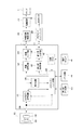
図4はこのように動画処理用のメモリ回路も汎用のSDRAMを用いた場合のカメラ一体型VTR100の構成を示す図である。図4において、図1と同様の構成については同一番号を付し、その詳細な説明は省略する。
【0040】
図4において、動画モードにおいては、縮小回路113により縮小された画像信号がメモリインターフェイス回路123に出力される。メモリインターフェイス回路123は制御CPU133からの制御信号に応じて書き込みアドレスを発生し、縮小回路113から出力された画像信号をメモリ回路143に書き込む。そして、メモリインターフェイス回路123はメモリ回路143に記憶された画像信号を所定の出力タイミングに同期して読み出し、映像処理回路117に出力する。
【0041】
また、静止画モード時の動作は図1の装置と同様である。
【0042】
本形態では、メモリ回路143も汎用のSDRAMとすることで、更に使い勝手が向上する。
【0043】
即ち、撮像回路101にて用いられるCCDの画素数が36万画素程度の場合、メモリ回路143を32Mビット程度の汎用SDRAMとし、メモリ回路143の記憶領域を動画処理用領域と静止画処理用領域とに分けて使用することで、特に静止画メモリ回路125を設けることなく動画像データの処理と静止画像データの処理を実現することが可能となる。
【0044】
一方、CCDの画素数が増えた場合には、メモリ回路143に加え、新たに静止画メモリ回路125を追加することで、動画像データよりも画素数の多い静止画像データの処理を行うことが可能となる。
【0045】
このように、動画像処理用のメモリ回路143と静止画メモリ回路125のメモリインターフェイスを共通の汎用のSDRAM用インターフェイスとすることで、回路の大幅な設計変更することなく画素数が36万画素程度の画像信号から、100万画素を超えるような多画素の画像信号まで処理可能となる。
【0046】
なお、前述の実施形態では、静止画メモリ回路125として汎用のSDRAMを使っていたが、勿論これ以外のメモリを使用することも可能である。
【0047】
【発明の効果】
以上述べたように、本発明によれば、画像信号の画素数が変更した場合であっても容易に動画像、静止画像データの処理が可能となる。また、撮像された画像信号の画素数が変更された場合であっても集積回路の設計を変更することなく容易に静止画像データの処理を行うことが可能となる。
【図面の簡単な説明】
【図1】本発明が適用されるカメラ一体型VTRの構成を示す図である。
【図2】図1の装置にて用いる撮像素子のフィルタ構成を示す図である。
【図3】図1の装置による縮小処理を示す図である。
【図4】本発明が適用されるカメラ一体型VTRの他の構成を示す図である。[0001]
BACKGROUND OF THE INVENTION
The present invention relates to an image processing apparatus, and more particularly to an apparatus for processing image signals having different numbers of pixels using a memory.
[0002]
[Prior art]
2. Description of the Related Art Conventionally, a video camera integrated digital VTR that records an image signal taken by a video camera on a magnetic tape as a digital signal is known. In recent years, a digital VTR that has a memory card slot, records moving image data on a magnetic tape as usual, and can record a still image on the memory card has been developed.
[0003]
[Problems to be solved by the invention]
On the other hand, with the recent improvement in semiconductor technology, the number of CCD pixels has increased dramatically, and it is considered that still images can be taken and recorded using a CCD with a larger number of pixels than the conventional digital VTR. It is done.
[0004]
However, the conventional digital is designed on the assumption that moving image data and still image data are signals having the same number of pixels. Therefore, when the number of pixels of the CCD increases as a result and as a result, the number of pixels of still image data increases, it cannot be easily handled.
[0005]
In recent years, in order to stabilize circuit characteristics and reduce power consumption, it is common to arrange each circuit such as a moving image processing circuit including a memory and a still image processing circuit on the same integrated circuit. .
[0006]
However, when the number of pixels of an image signal increases, a memory having a storage capacity corresponding to the number of pixels of image data is required especially for still image processing. However, even the memory for still image processing is on the same integrated circuit. In this case, only the memory circuit cannot be expanded or replaced with one having a larger capacity. For this reason, it is necessary to redesign an integrated circuit each time the number of pixels of the image signal is increased, which requires great labor and cost.
[0007]
An object of the present invention is to solve the above-described problems.
[0008]
Another object of the present invention is to make it possible to easily process moving images and still image data even when the number of pixels of the image signal is changed.
[0009]
Still another object of the present invention is to make it possible to easily process still image data without changing the design of the integrated circuit even when the number of pixels of the image signal is changed.
[0010]
[Means for Solving the Problems]
The present invention provides an image pickup means for outputting an image signal having a first pixel number larger than a predetermined number of pixels corresponding to a predetermined recording format, and an image signal having the first number of pixels output from the image pickup means. Conversion means for converting the image signal with the predetermined number of pixels, and a first memory having a storage capacity corresponding to the predetermined number of pixels and storing the image signal with the predetermined number of pixels output from the conversion means And a second memory having a storage capacity corresponding to the first number of pixels and storing an image signal of the first number of pixels output from the imaging means, and generating an address of the second memory A memory interface for writing the image signal of the first number of pixels output from the imaging means into the second memory and reading the image signal of the first number of pixels from the second memory; 1 me Recording means for recording the image signal of the predetermined number of pixels stored in the recording medium on the recording medium as moving image data in accordance with the predetermined recording format; and the first pixel read from the second memory A still image processing means for outputting a number of image signals as still image data, the conversion means, the first memory, the memory interface and the still image processing means are arranged on the same integrated circuit, and the imaging The means, the recording means, and the second memory are configured as circuits independent of the integrated circuit.
[0011]
DETAILED DESCRIPTION OF THE INVENTION
Hereinafter, embodiments of the present invention will be described.
[0012]
FIG. 1 is a block diagram showing the configuration of a camera-integrated
[0013]
In FIG. 1,
[0014]
When reading out image data from the CCD, in the moving image mode, it is common to read out pixels by adding two adjacent pixels. When the readout operation of the
[0015]
For example, in the arrangement of FIG. 2, the image signal of the first field is read out in the order of N lines + (N + 1) lines, (N + 2) lines + (N + 3) lines, and the image of the second field. The signals are read in the order of (N + 1) line + (N + 2) line, (N + 3) line + (N + 4) line.
[0016]
The digital image signal output from the
[0017]
The
[0018]
The image signal processed by the
[0019]
The image signal stored in the
[0020]
The video
[0021]
Next, the still image mode will be described. In the still image mode, one frame of the image signal output from the
[0022]
When the still image recording switch of the
[0023]
That is, the
[0024]
For example, in the case of the filter arrangement shown in FIG. 2, in the non-addition readout, the image signal of the first field is read in the order of N lines and (N + 2) lines, and the image signal of the second field is (N + 1) lines, (N + 3). ) In the order of the lines, the pixels in the adjacent lines are read without being added.
[0025]
Thus, the image signal of one frame input from the
[0026]
The
[0027]
In this embodiment, a general-purpose SDRAM (Synchronous Dynamic RAM) is used as the still
[0028]
One frame of image data written in the still
[0029]
Similarly to the moving image mode, the camera
[0030]
The image signal of one frame converted into the luminance signal and the color difference signal and written in the
[0031]
The still
[0032]
Here, in FIG. 1, the camera
[0033]
In other words, in this embodiment, most of the circuits related to moving image processing and still image processing are placed on the same integrated circuit, thereby achieving uniform circuit characteristics and suppressing power consumption. Of the circuits related to moving image processing and still pixel processing, the still
[0034]
That is, when the number of CCD pixels used in the
[0035]
In the moving
[0036]
In consideration of the increase in the number of pixels of the image signal as described above, it is desirable to secure a sufficient address in advance in the
[0037]
As for the storage capacity of the still
[0038]
In the apparatus of FIG. 1, the moving image
[0039]
FIG. 4 is a diagram showing the configuration of the camera-integrated
[0040]
In FIG. 4, in the moving image mode, the image signal reduced by the
[0041]
The operation in the still image mode is the same as that of the apparatus in FIG.
[0042]
In this embodiment, the
[0043]
That is, when the number of CCD pixels used in the
[0044]
On the other hand, when the number of pixels of the CCD increases, a still
[0045]
As described above, the memory interface of the moving image
[0046]
In the above-described embodiment, a general-purpose SDRAM is used as the still
[0047]
【The invention's effect】
As described above, according to the present invention, it is possible to easily process moving images and still image data even when the number of pixels of the image signal is changed. In addition, even when the number of pixels of the captured image signal is changed, still image data can be easily processed without changing the design of the integrated circuit.
[Brief description of the drawings]
FIG. 1 is a diagram showing a configuration of a camera-integrated VTR to which the present invention is applied.
FIG. 2 is a diagram illustrating a filter configuration of an image sensor used in the apparatus of FIG.
FIG. 3 is a diagram illustrating a reduction process performed by the apparatus of FIG. 1;
FIG. 4 is a diagram showing another configuration of a camera-integrated VTR to which the present invention is applied.
Claims (1)
前記撮像手段から出力された前記第1の画素数の画像信号を前記所定の画素数の画像信号に変換する変換手段と、
前記所定の画素数に対応した記憶容量を持ち、前記変換手段から出力される前記所定の画素数の画像信号を記憶する第1のメモリと、
前記第1の画素数に対応した記憶容量を持ち、前記撮像手段より出力された前記第1の画素数の画像信号を記憶する第2のメモリと、
前記第2のメモリのアドレスを発生し、前記撮像手段より出力された前記第1の画素数の画像信号を前記第2のメモリに書き込むと共に前記第2のメモリより前記第1の画素数の画像信号を読み出すメモリインターフェイスと、
前記第1のメモリに記憶されている前記所定の画素数の画像信号を、前記所定の記録フォーマットに従って動画像データとして記録媒体に記録する記録手段と、
前記第2のメモリから読み出された前記第1の画素数の画像信号を静止画像データとして出力する静止画処理手段とを備え、
前記変換手段、前記第1のメモリ、前記メモリインターフェイス及び前記静止画処理手段を同一の集積回路上に配置し、前記撮像手段、前記記録手段及び前記第2のメモリを前記集積回路とは独立した回路として構成したことを特徴とする画像処理装置。Imaging means for outputting an image signal having a first number of pixels larger than a predetermined number of pixels corresponding to a predetermined recording format;
Conversion means for converting the image signal of the first number of pixels output from the imaging means into the image signal of the predetermined number of pixels;
A first memory having a storage capacity corresponding to the predetermined number of pixels and storing the image signal of the predetermined number of pixels output from the conversion unit;
A second memory having a storage capacity corresponding to the first number of pixels and storing an image signal of the first number of pixels output from the imaging means;
An address of the second memory is generated, the image signal of the first number of pixels output from the imaging means is written into the second memory, and the image of the first number of pixels from the second memory A memory interface for reading signals;
Recording means for recording the image signal of the predetermined number of pixels stored in the first memory on a recording medium as moving image data according to the predetermined recording format;
Still image processing means for outputting the image signal of the first number of pixels read from the second memory as still image data;
The converting means, the first memory, the memory interface, and the still image processing means are arranged on the same integrated circuit, and the imaging means, the recording means, and the second memory are independent of the integrated circuit. An image processing apparatus configured as a circuit.
Priority Applications (2)
| Application Number | Priority Date | Filing Date | Title |
|---|---|---|---|
| JP2000374233A JP4454837B2 (en) | 2000-12-08 | 2000-12-08 | Image processing device |
| US10/000,087 US7317477B2 (en) | 2000-12-08 | 2001-12-04 | Image pickup apparatus for processing an image signal by using memory |
Applications Claiming Priority (1)
| Application Number | Priority Date | Filing Date | Title |
|---|---|---|---|
| JP2000374233A JP4454837B2 (en) | 2000-12-08 | 2000-12-08 | Image processing device |
Publications (3)
| Publication Number | Publication Date |
|---|---|
| JP2002176611A JP2002176611A (en) | 2002-06-21 |
| JP2002176611A5 JP2002176611A5 (en) | 2008-01-24 |
| JP4454837B2 true JP4454837B2 (en) | 2010-04-21 |
Family
ID=18843463
Family Applications (1)
| Application Number | Title | Priority Date | Filing Date |
|---|---|---|---|
| JP2000374233A Expired - Fee Related JP4454837B2 (en) | 2000-12-08 | 2000-12-08 | Image processing device |
Country Status (2)
| Country | Link |
|---|---|
| US (1) | US7317477B2 (en) |
| JP (1) | JP4454837B2 (en) |
Families Citing this family (9)
| Publication number | Priority date | Publication date | Assignee | Title |
|---|---|---|---|---|
| US5914787A (en) * | 1992-11-19 | 1999-06-22 | Olympus Optical Co., Ltd. | Electronic imaging apparatus |
| US6961083B2 (en) * | 2001-12-21 | 2005-11-01 | Hewlett-Packard Development Company, L.P. | Concurrent dual pipeline for acquisition, processing and transmission of digital video and high resolution digital still photographs |
| JP3902525B2 (en) * | 2002-09-05 | 2007-04-11 | 三洋電機株式会社 | Image signal processing device |
| US20040051793A1 (en) * | 2002-09-18 | 2004-03-18 | Tecu Kirk S. | Imaging device |
| JP4902136B2 (en) * | 2005-04-28 | 2012-03-21 | キヤノン株式会社 | Imaging apparatus, imaging method, and program |
| JP4911619B2 (en) * | 2007-09-11 | 2012-04-04 | 三洋電機株式会社 | Image data processing device |
| US20090066808A1 (en) * | 2007-09-11 | 2009-03-12 | Sanyo Electric Co., Ltd. | Image-data processing apparatus and data-processing circuit |
| CN104869381B (en) * | 2014-02-25 | 2017-07-25 | 炬芯(珠海)科技有限公司 | A kind of image processing system, method and device |
| JP6205654B2 (en) * | 2015-04-07 | 2017-10-04 | エスゼット ディージェイアイ テクノロジー カンパニー リミテッドSz Dji Technology Co.,Ltd | Image processing method and image processing apparatus |
Family Cites Families (7)
| Publication number | Priority date | Publication date | Assignee | Title |
|---|---|---|---|---|
| JP2525385B2 (en) * | 1986-12-18 | 1996-08-21 | キヤノン株式会社 | Imaging device |
| US5262871A (en) * | 1989-11-13 | 1993-11-16 | Rutgers, The State University | Multiple resolution image sensor |
| US6085348A (en) * | 1990-10-17 | 2000-07-04 | Canon Kabushiki Kaisha | Error correction code encoder and decoder |
| JP3266932B2 (en) * | 1992-05-18 | 2002-03-18 | キヤノン株式会社 | Reproduction apparatus and method |
| JPH10108121A (en) * | 1996-09-25 | 1998-04-24 | Nikon Corp | Electronic camera |
| JP2000023079A (en) * | 1998-07-03 | 2000-01-21 | Sony Corp | Image recording and reproducing device |
| JP2000115790A (en) * | 1998-09-30 | 2000-04-21 | Fuji Photo Optical Co Ltd | Image pickup device |
-
2000
- 2000-12-08 JP JP2000374233A patent/JP4454837B2/en not_active Expired - Fee Related
-
2001
- 2001-12-04 US US10/000,087 patent/US7317477B2/en not_active Expired - Fee Related
Also Published As
| Publication number | Publication date |
|---|---|
| US7317477B2 (en) | 2008-01-08 |
| US20020081104A1 (en) | 2002-06-27 |
| JP2002176611A (en) | 2002-06-21 |
Similar Documents
| Publication | Publication Date | Title |
|---|---|---|
| US5444483A (en) | Digital electronic camera apparatus for recording still video images and motion video images | |
| US7432958B2 (en) | Image pickup apparatus with function of adjusting incident light quantity | |
| JP3822380B2 (en) | Image signal processing device | |
| JP3348917B2 (en) | Image signal processing device | |
| JP4454837B2 (en) | Image processing device | |
| US7688361B2 (en) | Image processor including memory controller which starts reading image data before writing screenful of image data is completed | |
| US7064780B2 (en) | Image recording apparatus with selection of still image to be recorded from multi-picture display | |
| JP4027122B2 (en) | Imaging apparatus and control method thereof | |
| KR20090064278A (en) | Recording apparatus, replaying apparatus, recording method, replaying method and program recording medium | |
| JPH0549000A (en) | Electronic camera | |
| JP3679592B2 (en) | Signal processing apparatus and imaging apparatus | |
| JP2000115693A (en) | Image data recording method and device, image data reproducing method and device, information recording medium and computer-readable recording medium | |
| JP2732941B2 (en) | Image signal processing device | |
| JPH01218188A (en) | Image signal recorder | |
| JP3484928B2 (en) | Video signal recording and playback device | |
| JP4428801B2 (en) | Signal processing apparatus and method | |
| JP4298935B2 (en) | Digital still camera and operation control method thereof | |
| JP2001057647A (en) | Device and method for image pickup | |
| JP3846733B2 (en) | Image shooting device | |
| JP3745605B2 (en) | Electronic still camera | |
| JPH08298644A (en) | Picture data recording device and its method | |
| JP2001218165A (en) | Device and method for recording digital signal, and recording medium | |
| JP3647102B2 (en) | Imaging device | |
| JP3768987B2 (en) | Imaging device | |
| JPH0292181A (en) | Image pickup and reproducing system for electronic camera |
Legal Events
| Date | Code | Title | Description |
|---|---|---|---|
| A521 | Request for written amendment filed |
Free format text: JAPANESE INTERMEDIATE CODE: A523 Effective date: 20071204 |
|
| A621 | Written request for application examination |
Free format text: JAPANESE INTERMEDIATE CODE: A621 Effective date: 20071204 |
|
| A977 | Report on retrieval |
Free format text: JAPANESE INTERMEDIATE CODE: A971007 Effective date: 20091111 |
|
| A131 | Notification of reasons for refusal |
Free format text: JAPANESE INTERMEDIATE CODE: A131 Effective date: 20091117 |
|
| A521 | Request for written amendment filed |
Free format text: JAPANESE INTERMEDIATE CODE: A523 Effective date: 20100108 |
|
| TRDD | Decision of grant or rejection written | ||
| RD04 | Notification of resignation of power of attorney |
Free format text: JAPANESE INTERMEDIATE CODE: A7424 Effective date: 20100201 |
|
| A01 | Written decision to grant a patent or to grant a registration (utility model) |
Free format text: JAPANESE INTERMEDIATE CODE: A01 Effective date: 20100202 |
|
| A01 | Written decision to grant a patent or to grant a registration (utility model) |
Free format text: JAPANESE INTERMEDIATE CODE: A01 |
|
| A61 | First payment of annual fees (during grant procedure) |
Free format text: JAPANESE INTERMEDIATE CODE: A61 Effective date: 20100203 |
|
| FPAY | Renewal fee payment (event date is renewal date of database) |
Free format text: PAYMENT UNTIL: 20130212 Year of fee payment: 3 |
|
| R150 | Certificate of patent or registration of utility model |
Free format text: JAPANESE INTERMEDIATE CODE: R150 |
|
| FPAY | Renewal fee payment (event date is renewal date of database) |
Free format text: PAYMENT UNTIL: 20140212 Year of fee payment: 4 |
|
| LAPS | Cancellation because of no payment of annual fees |