JP4442338B2 - Wireless communication system, wireless communication apparatus, wireless communication method, and computer program - Google Patents
Wireless communication system, wireless communication apparatus, wireless communication method, and computer program Download PDFInfo
- Publication number
- JP4442338B2 JP4442338B2 JP2004195932A JP2004195932A JP4442338B2 JP 4442338 B2 JP4442338 B2 JP 4442338B2 JP 2004195932 A JP2004195932 A JP 2004195932A JP 2004195932 A JP2004195932 A JP 2004195932A JP 4442338 B2 JP4442338 B2 JP 4442338B2
- Authority
- JP
- Japan
- Prior art keywords
- station
- communication
- beacon
- time synchronization
- communication station
- Prior art date
- Legal status (The legal status is an assumption and is not a legal conclusion. Google has not performed a legal analysis and makes no representation as to the accuracy of the status listed.)
- Expired - Fee Related
Links
Images


Classifications
-
- H—ELECTRICITY
- H04—ELECTRIC COMMUNICATION TECHNIQUE
- H04W—WIRELESS COMMUNICATION NETWORKS
- H04W56/00—Synchronisation arrangements
- H04W56/001—Synchronization between nodes
- H04W56/002—Mutual synchronization
-
- H—ELECTRICITY
- H04—ELECTRIC COMMUNICATION TECHNIQUE
- H04W—WIRELESS COMMUNICATION NETWORKS
- H04W84/00—Network topologies
- H04W84/18—Self-organising networks, e.g. ad-hoc networks or sensor networks
Description
本発明は、無線LAN(Local Area Network)のように複数の無線局間で相互に通信を行なう無線通信システム、無線通信装置及び無線通信方法、並びにコンピュータ・プログラムに係り、特に、通信局同士が直接通信(ランダム・アクセス)を行なうことにより無線ネットワークが運営される無線通信システム、無線通信装置及び無線通信方法、並びにコンピュータ・プログラムに関する。 The present invention relates to a wireless communication system, a wireless communication apparatus, a wireless communication method, and a computer program for performing mutual communication between a plurality of wireless stations such as a wireless LAN (Local Area Network). The present invention relates to a wireless communication system, a wireless communication apparatus, a wireless communication method, and a computer program in which a wireless network is operated by performing direct communication (random access).
さらに詳しくは、本発明は、制御局と被制御局の関係を有しないで各通信局が自律分散的にネットワーク動作を行なう無線通信システム、無線通信装置及び無線通信方法、並びにコンピュータ・プログラムに係り、特に、自律的に動作する通信局が同期をとり合いながら干渉し合うことなく自律分散的な無線ネットワークを形成する無線通信システム、無線通信装置及び無線通信方法、並びにコンピュータ・プログラムに関する。 More specifically, the present invention relates to a radio communication system, a radio communication apparatus and a radio communication method, and a computer program in which each communication station performs network operation in an autonomous and distributed manner without having a relationship between a control station and a controlled station. In particular, the present invention relates to a wireless communication system, a wireless communication apparatus, a wireless communication method, and a computer program that form an autonomously distributed wireless network without causing interference between communication stations that operate autonomously while synchronizing.
複数のコンピュータを接続してLANを構成することにより、ファイルやデータなどの情報の共有化、プリンタなどの周辺機器の共有化を図ったり、電子メールやデータ・コンテンツの転送などの情報の交換を行なったりすることができる。 By connecting multiple computers and configuring a LAN, you can share information such as files and data, share peripheral devices such as printers, and exchange information such as e-mail and data / content transfer Can be done.
従来、光ファイバーや同軸ケーブル、あるいはツイストペア・ケーブルを用いて、有線でLAN接続することが一般的であったが、この場合、回線敷設工事が必要であり、手軽にネットワークを構築することが難しいとともに、ケーブルの引き回しが煩雑になる。また、LAN構築後も、機器の移動範囲がケーブル長によって制限されるため、不便である。そこで、有線方式によるLAN配線からユーザを解放するシステムとして、無線LANが注目されている。無線LANによれば、オフィスなどの作業空間において、有線ケーブルの大半を省略することができるので、パーソナル・コンピュータ(PC)などの通信端末を比較的容易に移動させることができる。 Conventionally, it has been common to use an optical fiber, a coaxial cable, or a twisted pair cable to connect to a wired LAN. In this case, however, a line laying work is required, and it is difficult to construct a network easily. The cable routing becomes complicated. In addition, even after LAN construction, the movement range of the device is limited by the cable length, which is inconvenient. Therefore, a wireless LAN has attracted attention as a system that releases users from wired LAN connection. According to the wireless LAN, most of the wired cables can be omitted in a work space such as an office, so that a communication terminal such as a personal computer (PC) can be moved relatively easily.
近年では、無線LANシステムの高速化、低価格化に伴い、その需要が著しく増加してきている。特に最近では、人の身の回りに存在する複数の電子機器間で小規模な無線ネットワークを構築して情報通信を行なうために、パーソナル・エリア・ネットワーク(PAN)の導入の検討が行なわれている。例えば、2.4GHz帯や、5GHz帯など、監督官庁の免許が不要な周波数帯域を利用して、異なった無線通信システムが規定されている。 In recent years, the demand for wireless LAN systems has increased remarkably with the increase in speed and cost. In particular, recently, in order to establish a small-scale wireless network between a plurality of electronic devices existing around a person and perform information communication, introduction of a personal area network (PAN) has been studied. For example, different wireless communication systems are defined using frequency bands that do not require a license from a supervisory authority, such as 2.4 GHz band and 5 GHz band.
無線ネットワークに関する標準的な規格として、IEEE(The Institute of Electrical and Electronics Engineers)802.11(例えば、非特許文献1を参照のこと)や、HiperLAN/2(例えば、非特許文献2又は非特許文献3を参照のこと)、IEEE802.15.3、Bluetooth通信などを挙げることができる。また、IEEE802.11規格については、無線通信方式や使用する周波数帯域の違いなどにより、IEEE802.11a(例えば、非特許文献4を参照のこと),b,gといった拡張規格が存在する。
As a standard for wireless networks, IEEE (The Institute of Electrical and Electronics Engineers) 802.11 (for example, refer to Non-Patent Document 1), HiperLAN / 2 (for example, Non-Patent
一般的には、無線技術を用いてローカル・エリア・ネットワークを構成するために、エリア内に「アクセス・ポイント」又は「コーディネータ」と呼ばれる制御局となる装置を1台設けて、この制御局の統括的な制御下でネットワークを形成する方法が用いられている。 In general, in order to configure a local area network using wireless technology, a device serving as a control station called an “access point” or “coordinator” is provided in the area. A method of forming a network under comprehensive control is used.
アクセス・ポイントを配置した無線ネットワークでは、ある通信装置から情報伝送を行なう場合に、まずその情報伝送に必要な帯域をアクセス・ポイントに予約して、他の通信装置における情報伝送と衝突が生じないように伝送路の利用を行なうという、帯域予約に基づくアクセス制御方法が広く採用されている。すなわち、アクセス・ポイントを配置することによって、無線ネットワーク内の通信装置が互いに同期をとるという同期的な無線通信を行なう。 In a wireless network in which an access point is arranged, when information is transmitted from a certain communication device, a bandwidth necessary for the information transmission is first reserved in the access point so that there is no collision with information transmission in another communication device. In this way, an access control method based on bandwidth reservation that uses a transmission line is widely adopted. That is, by arranging access points, synchronous wireless communication is performed in which communication devices in a wireless network are synchronized with each other.
ところが、アクセス・ポイントが存在する無線通信システムで、送信側と受信側の通信装置間で非同期通信を行なう場合には、必ずアクセス・ポイントを介した無線通信が必要になるため、伝送路の利用効率が半減してしまうという問題がある。 However, when asynchronous communication is performed between the communication device on the transmission side and the reception side in a wireless communication system in which an access point exists, wireless communication via the access point is always required. There is a problem that the efficiency is halved.
これに対し、無線ネットワークを構成する他の方法として、端末同士が直接非同期的に無線通信を行なう「アドホック(Ad−hoc)通信」が考案されている。とりわけ近隣に位置する比較的少数のクライアントで構成される小規模無線ネットワークにおいては、特定のアクセス・ポイントを利用せずに、任意の端末同士が直接すなわちランダムな無線通信を行なうことができるアドホック通信が適当であると思料される。 On the other hand, as another method of configuring a wireless network, “ad-hoc communication” in which terminals perform wireless communication directly and asynchronously has been devised. In particular, in a small-scale wireless network composed of a relatively small number of clients located in the vicinity, ad hoc communication that allows arbitrary terminals to perform direct or random wireless communication without using a specific access point Is considered appropriate.
アドホック型無線通信システムには中央制御局が存在しないので、例えば家庭用電気機器からなるホーム・ネットワークを構成するのに適している。アドホック・ネットワークには、1台が故障又は電源オフになってもルーティングを自動的に変更するのでネットワークが破綻しにくい、移動局間でパケットを複数回ホップさせることにより高速データレートを保ったままで比較的遠くまでデータを伝送することができる、といった特徴がある。アドホック・システムにはいろいろな開発事例が知られている(例えば、非特許文献5を参照のこと)。 Since an ad hoc wireless communication system does not have a central control station, it is suitable for configuring a home network made up of household electrical devices, for example. In an ad hoc network, even if one unit fails or power is turned off, the routing is automatically changed so that the network is unlikely to break down. The high data rate can be maintained by hopping packets between mobile stations multiple times. There is a feature that data can be transmitted to a relatively long distance. Various development cases are known for ad hoc systems (for example, see Non-Patent Document 5).
例えば、IEEE802.11系の無線LANシステムでは、IEEE802.11におけるネットワーキングは、BSS(Basic Service Set)の概念に基づいている。BSSは、アクセス・ポイント (Access Point:制御局)のようなマスタが存在する「インフラ・モード」で定義されるBSSと、複数のMT(Mobile Terminal:移動局)のみにより構成される「アドホック・モード」で定義されるIBSS(Independent BSS)の2種類で構成される。後者のアドホック・モードでは、制御局を配さなくとも自律分散的にピア・ツウ・ピア(Peer to Peer)で動作する。そして、ビーコン送信時間になると各端末がランダムな期間をカウントし、その期間が終わるまでに他の端末のビーコンを受信しなかった場合に、自分がビーコンを送信する。 For example, in an IEEE802.11 wireless LAN system, networking in IEEE802.11 is based on the concept of BSS (Basic Service Set). The BSS is an “ad hoc network” composed of only a BSS defined in an “infrastructure mode” in which a master such as an access point (Access Point) exists and a plurality of MTs (Mobile Terminals). It consists of two types of IBSS (Independent BSS) defined in “Mode”. In the latter ad hoc mode, operation is performed in a peer-to-peer manner in an autonomous and distributed manner without providing a control station. When the beacon transmission time is reached, each terminal counts a random period, and when it does not receive a beacon of another terminal by the end of the period, it transmits a beacon.
ここで、IEEE802.11を例にとって、従来の無線ネットワーキングの詳細について説明する。 Here, details of the conventional wireless networking will be described using IEEE 802.11 as an example.
インフラ・モード:
インフラ・モードのBSSにおいては、無線通信システム内にコーディネイションを行なうアクセス・ポイントが必須である。すなわち、アクセス・ポイントは、自局周辺で電波の到達する範囲をBSSとしてまとめ、いわゆるセルラ・システムで言うところの「セル」を構成する。アクセス・ポイント近隣に存在する移動局は、アクセス・ポイントに収容され、BSSのメンバとしてネットワークに参入する。
Infrastructure mode:
In the infrastructure mode BSS, an access point for coordinating in the wireless communication system is essential. That is, the access point collects the range where radio waves reach around its own station as a BSS, and constitutes a “cell” in what is called a cellular system. A mobile station existing in the vicinity of the access point is accommodated in the access point and enters the network as a member of the BSS.
アクセス・ポイントは、適当な時間間隔でビーコンと呼ばれる制御信号を送信する。このビーコンを受信可能である移動局は、アクセス・ポイントが近隣に存在することを認識し、さらにアクセス・ポイントとの間でコネクション確立を行なう。 The access point transmits control signals called beacons at appropriate time intervals. A mobile station that can receive this beacon recognizes that an access point exists in the vicinity, and establishes a connection with the access point.
また、アクセス・ポイント周辺の移動局は、ビーコンを受信することにより、内部のTBTTフィールドをデコードすることにより次回のビーコン送信時刻を認識することが可能であるから、場合によっては(受信の必要がない場合には)、次回あるいは複数回先のTBTTまで受信機の電源を落としスリープ状態(後述)に入ることもある。 Also, mobile stations around the access point can recognize the next beacon transmission time by decoding the internal TBTT field by receiving a beacon. If not, the receiver may be turned off and enter a sleep state (described later) until the next time or a plurality of TBTTs ahead.
インフラ・モード時には、アクセス・ポイントのみが所定フレーム周期でビーコンを送信する。他方、周辺移動局はアクセス・ポイントからのビーコンを受信することでネットワークへの参入を果たし、自らはビーコンを送信しない。なお、本発明は、アクセス・ポイントのようなマスタ制御局の介在なしでネットワークを動作させることを主眼とし、インフラ・モードとは直接関連しないことから、インフラ・モードに関してはこれ以上説明を行なわない。 In the infrastructure mode, only the access point transmits a beacon at a predetermined frame period. On the other hand, neighboring mobile stations enter the network by receiving beacons from access points, and do not transmit beacons themselves. Note that the present invention focuses on operating the network without the intervention of a master control station such as an access point, and since it is not directly related to the infrastructure mode, no further explanation will be given regarding the infrastructure mode. .
アドホック・モード:
もう一方のアドホック・モード時のIEEE802.11の動作について、図27を参照しながら説明する。
Ad hoc mode:
The operation of IEEE 802.11 in the other ad hoc mode will be described with reference to FIG.
アドホック・モードのIBSSにおいては、移動局は複数の移動局同士でネゴシエーションを行なった後に自律的にIBSSを定義する。IBSSが定義されると、移動局群は、ネゴシエーションの末に、一定間隔毎にTBTTを定める。各移動局は自局内のクロックを参照することによりTBTTが到来したことを認識すると、ランダム時間の遅延の後、未だ誰もビーコンを送信していないと認識した場合にはビーコンを送信する。 In IBSS in ad hoc mode, a mobile station autonomously defines an IBSS after negotiating with a plurality of mobile stations. When IBSS is defined, the mobile station group determines TBTT at regular intervals at the end of the negotiation. When each mobile station recognizes that the TBTT has arrived by referring to the clock in its own station, it transmits a beacon when it recognizes that no one has yet transmitted a beacon after a random time delay.
図27に示す例では、2台の移動局がIBBSを構成する様子を示している。この場合、IBSSに属するいずれか一方の移動局が、TBTTが到来する毎にビーコンを送信することになる。また、各移動局から送出されるビーコンが衝突する場合も存在している。 In the example shown in FIG. 27, two mobile stations form an IBBS. In this case, any one of the mobile stations belonging to the IBSS transmits a beacon every time a TBTT arrives. In some cases, beacons sent from mobile stations collide.
また、IBSSにおいても、移動局は必要に応じて送受信機の電源を落とすスリープ状態(後述)に入ることがある。 Also in IBSS, the mobile station may enter a sleep state (described later) in which the power of the transceiver is turned off as necessary.
IEEE802.11における送受信手順:
アドホック環境の無線LANネットワークにおいては、一般的に隠れ端末問題が生じることが知られている。隠れ端末とは、ある特定の通信局間で通信を行なう場合、通信相手となる一方の通信局からは聞くことができるが他方の通信局からは聞くことができない通信局のことであり、隠れ端末同士ではネゴシエーションを行なうことができないため、送信動作が衝突する可能性がある。
Transmission / reception procedure in IEEE 802.11:
In a wireless LAN network in an ad hoc environment, it is generally known that a hidden terminal problem occurs. A hidden terminal is a communication station that can be heard from one communication station that is a communication partner but cannot be heard from the other communication station when communicating between specific communication stations. Since terminals cannot negotiate with each other, there is a possibility that transmission operations may collide.
隠れ端末問題を解決する方法論として、RTS/CTS手順によるCSMA/CAが知られている。IEEE802.11においてもこの方法論が採用されている。 As a methodology for solving the hidden terminal problem, CSMA / CA by the RTS / CTS procedure is known. This methodology is also adopted in IEEE 802.11.
ここで、CSMA(Carrier Sense Multiple Access with Collision Avoidance:搬送波感知多重アクセス)とは、キャリア検出に基づいて多重アクセスを行なう接続方式である。無線通信では自ら情報送信した信号を受信することが困難であることから、CSMA/CD(Collision Detection)ではなくCSMA/CA(Collision Avoidance)方式により、他の通信装置の情報送信がないことを確認してから、自らの情報送信を開始することによって、衝突を回避する。 Here, CSMA (Carrier Sense Multiple Access with Collision Avidance) is a connection method for performing multiple access based on carrier detection. Since it is difficult to receive a signal transmitted by itself in wireless communication, it is confirmed that there is no information transmission of other communication devices by CSMA / CA (Collision Aidance) method instead of CSMA / CD (Collision Detection). Then, the collision is avoided by starting the transmission of its own information.
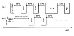
また、RTS/CTS方式では、データ送信元の通信局が送信要求パケットRTS(Request To Send)を送信し、データ送信先の通信局から確認通知パケットCTS(Clear To Send)を受信したことに応答してデータ送信を開始する。そして、隠れ端末はRTS又はCTSのうち少なくとも一方を受信すると、RTS/CTS手続に基づくデータ伝送が行なわれると予想される期間だけ自局の送信停止期間を設定することにより、衝突を回避することができる。送信局にとっての隠れ端末は、CTSを受信して送信停止期間を設定し、データ・パケットとの衝突を回避し、受信局にとっての隠れ端末は、RTSを受信して送信期間を停止し、ACKとの衝突を回避する。 Further, in the RTS / CTS system, the data transmission source communication station transmits a transmission request packet RTS (Request To Send) and responds to reception of the confirmation notification packet CTS (Clear To Send) from the data transmission destination communication station. To start data transmission. When the hidden terminal receives at least one of RTS and CTS, it avoids a collision by setting its own transmission stop period only during a period in which data transmission based on the RTS / CTS procedure is expected to be performed. Can do. The hidden terminal for the transmitting station receives the CTS and sets the transmission stop period to avoid collision with the data packet, the hidden terminal for the receiving station receives the RTS and stops the transmission period, and the ACK To avoid collisions.
スリープ状態での信号送受信手順:
IEEE802.11におけるネットワーキングでは、アドホック・モード時のIBSSにおいても、移動局は必要に応じて送受信機の電源を落とすスリープ状態に入ることがある。
Signal transmission / reception procedure in sleep mode:
In networking in IEEE802.11, even in IBSS in ad hoc mode, the mobile station may enter a sleep state in which the power of the transceiver is turned off as necessary.
IEEE802.11においてIBSSでスリープ・モードが適用されている場合には、TBTTからしばらくの時間帯がATIM(Announcement Traffic Indication Message)ウィンドウとして定義されている。このATIMウィンドウの時間帯は、IBSSに属するすべての移動局は受信機を動作させており、この時間帯であれば、基本的にはスリープ・モードで動作している移動局も受信が可能である。 When the sleep mode is applied by IBSS in IEEE802.11, a time zone from TBTT for a while is defined as an ATN (Announcement Traffic Indication Message) window. During this time period of the ATIM window, all mobile stations belonging to the IBSS operate the receiver, and in this time period, basically, the mobile stations operating in the sleep mode can also receive. is there.
各移動局は、自局が誰か宛ての情報を有している場合には、このATIMウィンドウの時間帯において、上記の通信相手宛にATIMパケットを送信することにより、自局が送信情報を保持していることを受信側に通達する。ATIMパケットを受信した移動局は、ATIMパケットを送信した局からの受信が終了するまで、受信機を動作させておく。 When each mobile station has information addressed to who it is, the mobile station holds transmission information by transmitting an ATIM packet to the communication partner in the time zone of this ATIM window. Notify the receiver that you are doing. The mobile station that has received the ATIM packet operates the receiver until reception from the station that has transmitted the ATIM packet is completed.
図28に示す例では、STA1、STA2、STA3の3台の移動局がIBSS内に存在している場合を例示している。TBTTが到来すると、STA1、STA2、STA3の各移動局はランダム時間にわたりメディア状態を監視しながらバックオフのタイマーを動作させる。同図に示す例では、STA1のタイマーが最も早期に消滅し、STA1がビーコンを送信している。STA1がビーコンを送信したため、これを受信したSTA2並びSTA3はビーコンを送信しない。 In the example shown in FIG. 28, a case where three mobile stations STA1, STA2, and STA3 exist in the IBSS is illustrated. When the TBTT arrives, the mobile stations STA1, STA2, and STA3 operate a back-off timer while monitoring the media state over a random time. In the example shown in the figure, the timer of STA1 disappears earliest and STA1 transmits a beacon. Since STA1 has transmitted a beacon, STA2 and STA3 that have received the beacon do not transmit a beacon.
また、図28に示す例では、STA1がSTA2宛の情報を保持しており、且つSTA2がSTA3への情報を保持している。このとき、STA1とSTA2は、ビーコンを送信/受信した後に、再度ランダム時間にわたり各々メディア状態を監視しながらバックオフのタイマーを動作させる。同図に示す例では、STA2のタイマーが先に消滅したため、まずSTA2からATIMメッセージがSTA3に宛てに送信される。STA3はATIMメッセージを受信すると、受信した旨をACK(Acknowledge)パケットを送信することによりSTA2にフィードバックする。 In the example shown in FIG. 28, STA1 holds information addressed to STA2, and STA2 holds information addressed to STA3. At this time, after transmitting / receiving the beacon, STA1 and STA2 operate the back-off timer while monitoring the media state again for a random time. In the example shown in the figure, since the timer of STA2 has disappeared first, an ATIM message is first transmitted from STA2 to STA3. When the STA3 receives the ATIM message, the STA3 feeds back the message to the STA2 by transmitting an ACK (Acknowledge) packet.
STA3からのACKが送信し終えると、STA1はさらにランダム時間にわたり各々メディア状態を監視しながらバックオフのタイマーを動作させる。タイマーが消滅すると、STA1はATIMパケットをSTA2に宛てて送信する。STA2はこれを受信した旨のACKパケットを返送することによりSTA1にフィードバックする。
When the transmission of the ACK from the
このようなATIMパケットとACKパケットのやり取りがATIMウィンドウ内で行なわれると、その後の区間においても、STA3はSTA2からの情報を受信するために受信機を動作させ、同様に、STA2はSTA1からの情報を受信するために受信機を動作させる。 When such an exchange between the ATIM packet and the ACK packet is performed within the ATIM window, STA3 operates the receiver to receive information from STA2 in the subsequent interval, and similarly, STA2 receives information from STA1. Operate the receiver to receive the information.
送信情報を保持しているSTA1並びSTA2は、ATIMウィンドウの終了とともに、ランダム時間にわたり各々メディア状態を監視しながらバックオフのタイマーを動作させる。図示の例では、STA2のタイマーが先に消滅したため、STA2からSTA3宛ての情報が先に伝送されている。この伝送終了の後、STA1は、再度ランダム時間にわたり各々メディア状態を監視しながらバックオフのタイマーを動作させ、タイマーが消滅したらSTA2宛のパケットを送信する。 The STA1 and the STA2 holding the transmission information operate a back-off timer while monitoring the media state for each random time as the ATIM window ends. In the illustrated example, since the timer of STA2 disappears first, information addressed to STA3 from STA2 is transmitted first. After the end of the transmission, STA1 operates the back-off timer again while monitoring each media state over a random time. When the timer expires, STA1 transmits a packet addressed to STA2.
上記の手順において、ATIMウィンドウ内でATIMパケットを受信しない通信局や、誰宛てにも情報を保持していない通信局は、次のTBTTまで送受信機の電源を落とし、消費電力を削減することが可能となる。 In the above procedure, a communication station that does not receive an ATIM packet within the ATIM window or a communication station that does not hold information for anyone can turn off the power of the transceiver until the next TBTT to reduce power consumption. It becomes possible.
上述したように、制御局と被制御局の関係を有しないで各通信局が自律分散的にネットワーク動作を行なう無線通信システムでは、各通信局はチャネル上で周期的にビーコン情報を報知することにより、近隣(すなわち通信可能範囲内)の他の通信局に自己の存在を知らしめるとともに、ネットワーク構成を通知する。通信局は伝送フレーム周期の先頭でビーコンを送信するので、伝送フレーム周期はビーコン間隔によって定義される。また、各通信局は、伝送フレーム周期に相当する期間だけチャネル上をスキャン動作することにより、周辺局から送信されるビーコン信号を発見し、ビーコンに記載されている情報を解読することによりネットワーク構成を知る(又はネットワークに参入する)ことができる。 As described above, in a wireless communication system in which each communication station performs network operation in an autonomous and distributed manner without having a relationship between a control station and a controlled station, each communication station periodically broadcasts beacon information on the channel. By notifying the other communication stations in the vicinity (that is, within the communicable range) of the existence of the self, the network configuration is notified. Since the communication station transmits a beacon at the beginning of the transmission frame period, the transmission frame period is defined by the beacon interval. In addition, each communication station scans the channel for a period corresponding to the transmission frame period, thereby discovering a beacon signal transmitted from a peripheral station and decoding the information described in the beacon. (Or enter the network).
このような無線通信システムでは、各通信局において周辺局との時間の同期を確保しながら、上述のようなビーコン情報の報知やビーコン情報の管理などを周期的に行なう必要がある。また、通信局がフレーム周期内で帯域を予約する、あるいは優先利用期間を設定するなど時間同期をベースにしたアクセス方式においては、通信局同士で時間の同期を確保することは極めて重要な問題である。 In such a wireless communication system, it is necessary to periodically perform notification of beacon information, management of beacon information, and the like as described above while ensuring time synchronization with peripheral stations in each communication station. Also, in an access method based on time synchronization, such as when a communication station reserves a bandwidth within a frame period or sets a preferential use period, ensuring time synchronization between communication stations is a very important issue. is there.
従来の時間同期が必要となる無線通信システムの多くは、制御局の介在により、各通信局がそれぞれ制御局と時間の同期を確保し、同一ネットワークに存在する各通信局間の時間の同期を確保することが可能である。 Many conventional wireless communication systems that require time synchronization ensure that each communication station ensures time synchronization with the control station through the intervention of the control station, and synchronizes time between each communication station in the same network. It is possible to secure.
これに対し、各通信局が自律分散的にネットワーク動作を行なう無線通信システムでは、制御局と被制御局の関係を有しないことから、従来のような時間同期を確保する方法は適用することができない。例えば、自律分散型の無線通信システムにおいて、マスタ及びスレーブとなる関係を通信局間で一時的に定義し、一時的に制御局となるような通信局を同一ネットワーク内において作ることで従来の方法を適用し時間同期を確保するという方法も考えられる。しかしながら、どのようにしてマスタとスレーブを決定するか、マスタがネットワークから消滅した場合にどのようにマスタを再設定するかなどの処理が複雑である。 On the other hand, in a wireless communication system in which each communication station performs network operation in an autonomous and distributed manner, since there is no relationship between a control station and a controlled station, a conventional method of ensuring time synchronization can be applied. Can not. For example, in an autonomous decentralized wireless communication system, the relationship between a master and a slave is temporarily defined between communication stations, and a communication station that temporarily becomes a control station is created in the same network. A method is also conceivable in which time synchronization is ensured by applying. However, the process of determining the master and the slave and how to reset the master when the master disappears from the network is complicated.
また、アクセス・ポイントなどを経由して通信が行なわれるインフラストラクチャ通信と比較して、アドホック通信では各通信局の処理が大きいことから、処理がさらに増大することは好ましくない。このことから、自律分散型の通信システムでは、比較的単純な処理で各通信局間との時間同期が確保できる技術が必要である。 Further, since the processing of each communication station is larger in ad hoc communication than in infrastructure communication in which communication is performed via an access point or the like, it is not preferable to further increase the processing. For this reason, an autonomous distributed communication system requires a technique that can ensure time synchronization with each communication station by a relatively simple process.
本発明は上述したような技術的課題を勘案したものであり、その主な目的は、制御局と被制御局の関係を有しないで各通信局が自律分散的にネットワーク動作を好適に行なうことができる、優れた無線通信システム、無線通信装置及び無線通信方法、並びにコンピュータ・プログラムを提供することにある。 The present invention takes into account the technical problems as described above, and its main purpose is that each communication station suitably performs network operations in an autonomous and distributed manner without having a relationship between the control station and the controlled station. It is an object to provide an excellent wireless communication system, wireless communication apparatus, wireless communication method, and computer program capable of performing the above.
本発明のさらなる目的は、自律的に動作する通信局が同期をとり合いながら干渉し合うことなく自律分散的な無線ネットワークを形成することができる、優れた無線通信システム、無線通信装置及び無線通信方法、並びにコンピュータ・プログラムを提供することにある。 A further object of the present invention is to provide an excellent wireless communication system, wireless communication device, and wireless communication capable of forming an autonomously distributed wireless network without interfering with each other while the autonomously operating communication stations maintain synchronization. It is to provide a method and a computer program.
本発明のさらなる目的は、自律分散的な無線ネットワークにおいて、通信局が比較的単純で負荷の低い処理により他の通信局との間で時間同期をとることができる、優れた無線通信システム、無線通信装置及び無線通信方法、並びにコンピュータ・プログラムを提供することにある。 A further object of the present invention is to provide an excellent radio communication system and radio in which a communication station can perform time synchronization with other communication stations by a relatively simple and low-load process in an autonomous distributed wireless network. To provide a communication device, a wireless communication method, and a computer program.
本発明は、上記課題を参酌してなされたものであり、その第1の側面は、制御局と被制御局の関係を有しないで各通信局の自律分散的な動作により構築される無線通信システムであって、
各通信局は、周辺局との時間同期状況を確認し、時間同期の修正が必要かどうかを判別し、時間同期の修正が必要な場合には、時間同期の修正処理を必ず実行するか又は所定の確率で修正処理を実行する、
ことを特徴とする無線通信システムである。時間同期の修正を行なう場合、通信局は、周辺局との同期タイミングの相違を示すパラメータの推定を行ない、該推定パラメータに基づいて時間同期の基準とする通信局を決定し、該基準となる通信局との時間同期を図る。
The present invention has been made in consideration of the above-mentioned problems, and a first aspect thereof is wireless communication constructed by autonomously distributed operation of each communication station without having a relationship between the control station and the controlled station. A system,
Each communication station checks the time synchronization status with surrounding stations, determines whether it is necessary to correct time synchronization, and if correction of time synchronization is required, always execute the correction processing of time synchronization or Execute the correction process with a predetermined probability,
This is a wireless communication system. When correcting time synchronization, the communication station estimates a parameter indicating a difference in synchronization timing with the peripheral station, determines a communication station as a reference for time synchronization based on the estimated parameter, and becomes the reference Time synchronization with the communication station is planned.
但し、ここで言う「システム」とは、複数の装置(又は特定の機能を実現する機能モジュール)が論理的に集合した物のことを言い、各装置や機能モジュールが単一の筐体内にあるか否かは特に問わない。 However, “system” here refers to a logical collection of a plurality of devices (or functional modules that realize specific functions), and each device or functional module is in a single housing. It does not matter whether or not.
但し、ここで言う「システム」とは、複数の装置(又は特定の機能を実現する機能モジュール)が論理的に集合した物のことを言い、各装置や機能モジュールが単一の筐体内にあるか否かは特に問わない。 However, “system” here refers to a logical collection of a plurality of devices (or functional modules that realize specific functions), and each device or functional module is in a single housing. It does not matter whether or not.
本発明に係る無線通信システムにおいては、コーディネータを特に配置しない。各通信局はビーコン情報を報知することにより、近隣(すなわち通信範囲内)の他の通信局に自己の存在を知らしめるとともに、ネットワーク構成を通知する。また、ある通信局の通信範囲に新規に参入する通信局は、ビーコン信号を受信することにより、通信範囲に突入したことを検知するとともに、ビーコンに記載されている情報を解読することによりネットワーク構成を知ることができる。 In the wireless communication system according to the present invention, no coordinator is particularly arranged. Each communication station notifies the beacon information to notify other communication stations in the vicinity (that is, within the communication range) of its own existence and notifies the network configuration. In addition, a communication station that newly enters the communication range of a certain communication station detects that it has entered the communication range by receiving a beacon signal, and decodes information described in the beacon to configure the network configuration Can know.
周辺に通信局がいない場合、通信局は適当なタイミングでビーコンを送信し始めることができる。以降、通信範囲内に新規に参入する通信局は、既存のビーコン配置と衝突しないように、自己のビーコン送信タイミングを設定する。このとき、各通信局は、例えば、ビーコン送信の直後に優先利用領域を獲得することから、既存の通信局が設定したビーコン間隔のほぼ真中のタイミングで新規参入局のビーコン送信タイミングを順次設定していくというアルゴリズムに従って、ビーコン配置が行なわれる。 If there is no communication station in the vicinity, the communication station can start transmitting a beacon at an appropriate timing. Thereafter, the communication station that newly enters the communication range sets its own beacon transmission timing so as not to collide with the existing beacon arrangement. At this time, for example, each communication station acquires a priority use area immediately after beacon transmission, so that the beacon transmission timings of new entry stations are sequentially set at almost the middle of the beacon interval set by the existing communication stations. The beacon placement is performed according to the algorithm of going.
ここで、無線通信システムでは、各通信局において周辺局との時間の同期を確保しながら、上述のようなビーコン情報の報知やビーコン情報の管理などを周期的に行なう必要がある。例えば、各通信局がフレーム周期内で帯域を予約する、あるいは優先利用期間を設定するなど時間同期をベースにしたアクセス方式においては、時間の同期確保は重要な問題である。 Here, in the wireless communication system, it is necessary to periodically perform notification of beacon information, management of beacon information, and the like as described above while ensuring time synchronization with peripheral stations in each communication station. For example, in an access method based on time synchronization such that each communication station reserves a bandwidth within a frame period or sets a preferential use period, ensuring time synchronization is an important issue.
特定の制御局の管理下に置かれる無線通信システムでは、制御局の介在により、各通信局がそれぞれ制御局と時間の同期を確保し、同一ネットワークに存在する各通信局間の時間の同期を確保することが可能である。これに対し、制御局と被制御局の関係を有しない自律分散型の無線通信システムでは、制御局となる通信局が存在しないことから、このような時間同期を確保する方法は適用することができない、という問題がある。 In a wireless communication system placed under the control of a specific control station, each communication station ensures time synchronization with the control station through the intervention of the control station, and time synchronization between communication stations existing in the same network is achieved. It is possible to secure. In contrast, in an autonomous distributed wireless communication system that does not have a relationship between a control station and a controlled station, there is no communication station that serves as a control station, and thus such a method for ensuring time synchronization can be applied. There is a problem that it is not possible.
そこで、本発明では、自律分散的に動作する各通信局が、周辺局との同期タイミングの相違を示すパラメータの推定を行ない、推定パラメータに基づいて時間同期の基準とする通信局を決定し、その基準となる通信局と時間同期を図ることにより、同一ネットワーク内に存在するすべての通信局間との時間同期の確保を実現するようにした。 Therefore, in the present invention, each communication station operating in an autonomous distributed manner estimates a parameter indicating a difference in synchronization timing with a peripheral station, determines a communication station to be a reference for time synchronization based on the estimated parameter, By ensuring time synchronization with the reference communication station, it is possible to ensure time synchronization with all communication stations existing in the same network.
すなわち、ビーコン信号などの各通信局間で周期的に交換されるパケットの受信時刻から自局の時間クロックのタイミングを基準として他局の時間スロットの先頭タイミングを推定する。そして、ある時間区間内において最も時間スロットの先頭タイミングが遅れている通信局に自局の時間スロットを合わせることにより、自律分散的に同一ネットワーク内の通信局間における時間同期を図る。 That is, the head timing of the time slot of the other station is estimated from the reception time of a packet periodically exchanged between the communication stations such as a beacon signal with reference to the timing of the time clock of the local station. Then, by synchronizing the time slot of the own station with the communication station having the most delayed time slot start timing within a certain time interval, time synchronization between communication stations in the same network is achieved in an autonomous and distributed manner.
また、別のネットワークとの交錯や新規通信局の参入などによりビーコンの予定していた送信タイミングに狂いが生じた場合において、周辺局はそのビーコンの受信時刻から他局の時間スロットの先頭タイミングを推定するため、実際とは異なる時間スロット・タイミングを推定し、その結果、時間同期にズレが生じる恐れがある。 Also, if the beacon transmission timing is incorrect due to crossing with another network or entering a new communication station, the peripheral station determines the start timing of the time slot of the other station from the beacon reception time. In order to estimate, a time slot timing different from the actual time is estimated, and as a result, there is a possibility that time synchronization will be shifted.
そこで、予定時刻に送出されたビーコンであるかどうかを通知するフラグをビーコン情報に追加しておくことようにしてもよい。このような場合、ビーコン受信局側では、フラグを参照することで、誤って推定された時間スロットに同期を合わせる頻度を減らし、信頼性の高いネットワーク内の時間同期を確保することができる。 Therefore, a flag for notifying whether the beacon is transmitted at the scheduled time may be added to the beacon information. In such a case, the beacon receiving station side can refer to the flag to reduce the frequency of synchronization with the time slot that has been estimated incorrectly, and to ensure time synchronization within the highly reliable network.
また、周辺局と時間の同期がとれていない通信局において、予定時刻にビーコンが送信できない状況が続いた場合には、上述したような周辺局との周期タイミングの相違の推定に基づく時間同期確保方法では、自局及び周辺局のどちらにおいても時間スロットの修正が行なわれず、その結果、いつまでも時間同期がずれた状況が続くという可能性がある。 In addition, if a communication station that is not synchronized with the surrounding station continues to transmit a beacon at the scheduled time, ensuring time synchronization based on the estimation of the difference in period timing with the surrounding station as described above In the method, the time slot is not corrected in either the local station or the peripheral station, and as a result, there is a possibility that the situation in which time synchronization is shifted indefinitely continues.
そこで、本発明では、自局において予定時刻にビーコンが送信できない状況が続いた場合であって、周辺局と時間同期にズレがあると検出された際には、自局の時間スロットの先頭タイミングがある時間区間内において周辺局に比べ最も遅れていたとしても、自局より他局に時間スロットのタイミングに合わせることで、時間同期ずれの状況が続くことを防ぐようにしてもよい。 Therefore, in the present invention, when a situation in which the beacon cannot be transmitted at the scheduled time continues in the own station, and when it is detected that there is a time synchronization deviation with the peripheral station, the start timing of the time slot of the own station Even if it is the most delayed compared to the peripheral stations within a certain time interval, it may be possible to prevent the situation of time synchronization deviation from continuing by adjusting the timing of the time slot from the own station to other stations.
また、上述したような時間同期の修正処理を適用した場合、複数の通信局間において、偶然に同一のタイミングで時間同期のずれを修正しようとすると、時間同期が収束しない可能性がある。それが、定常的なパターンで繰り返された場合には、いつまでも時間同期が収束しないという懸念がある。 In addition, when the time synchronization correction process as described above is applied, there is a possibility that the time synchronization may not converge if an attempt is made to correct the time synchronization deviation at the same timing between a plurality of communication stations. There is a concern that time synchronization will not converge indefinitely if it is repeated in a steady pattern.
そこで、本発明では、通信局は、時間同期にずれを検出した場合に、周辺局との時間同期の修正タイミングにある定常的なパターンが発生しないように確率的な処理を施すことにより、時間同期の修正が収束しない問題を回避するようにしてもよい。 Therefore, in the present invention, when a communication station detects a shift in time synchronization, the communication station performs a probabilistic process so as not to generate a steady pattern at the timing of correction of time synchronization with a peripheral station. The problem that the synchronization correction does not converge may be avoided.
また、消費電力の低減を目的として、周辺局とデータの送受信を行なっていない通信局において、ある一定区間のみデータの受信を行ない、それ以外の時間ではビーコンの送信のみを行なう間欠受信モードが多くの無線ネットワーク・システムで導入されている。しかしながら、上述したように、自局の時間スロット・タイミングの修正を確率的な処理で行なう場合、特に間欠受信する通信局においては次の時間同期処理までの間が間欠受信のために長時間になるため、時間同期の修正が行なわれるまでの時間が長時間化する恐れがある。 Also, for the purpose of reducing power consumption, there are many intermittent reception modes in which data is received only in a certain interval at a communication station that does not transmit / receive data to / from peripheral stations, and only beacon transmission is performed at other times. Introduced in wireless network systems. However, as described above, when correcting the time slot timing of its own station by stochastic processing, especially in a communication station receiving intermittently, the time until the next time synchronization processing is long because of intermittent reception. Therefore, there is a possibility that the time until the time synchronization is corrected becomes longer.
そこで、間欠受信する通信局を考慮した時間同期処理の方法として、確率α(0<α<1)で行なわれる自局の時間スロット・タイミングの修正において、間欠受信する通信局の方が通常の通信局よりも早期に時間同期処理が行なわれるように考慮する。さらに、時間同期ずれが検出されてから時間同期の修正が行なわれるまでの時間に閾値を設けることにより、特に間欠受信する通信局において問題となりうる時間同期ずれの検出から修正までの長時間化を防ぐようにしてもよい。 Therefore, as a method of time synchronization processing considering a communication station that receives intermittently, in the correction of the time slot timing of the own station performed with probability α (0 <α <1), the communication station that intermittently receives is more normal. Consider that time synchronization processing is performed earlier than the communication station. Furthermore, by setting a threshold for the time from when the time synchronization deviation is detected until the time synchronization correction is performed, it is possible to increase the time from detection to correction of the time synchronization deviation, which can be a problem particularly in intermittently receiving communication stations. You may make it prevent.
また、予定時刻以外のビーコンの送受信が継続している場合や、時間同期タイミングの誤差を推定し周辺局同士が互いに修正を続けている場合が発生したときには、いつまでも時間同期のずれが検出し続ける可能性が考えられる。また、周辺局との同期タイミングの相違を示すパラメータの推定に基づいて時間同期の基準とする通信局を決定して時間同期を図る場合、各通信局における同期タイミングの相違が基準局か否かを判断する値にちょうど一致するときには、いずれの通信局も時間同期の修正処理を実行しない可能性がある。 Also, when beacon transmission / reception other than the scheduled time continues, or when a time synchronization timing error is estimated and neighboring stations continue to correct each other, time synchronization deviation will continue to be detected forever. There is a possibility. In addition, when determining a communication station to be a reference for time synchronization based on estimation of a parameter indicating a difference in synchronization timing with a peripheral station and performing time synchronization, it is determined whether or not the difference in synchronization timing in each communication station is a reference station. When the values exactly match the value to be determined, there is a possibility that none of the communication stations executes the time synchronization correction process.
そこで、時間同期のずれが継続した場合、又は予定時刻以外のビーコンの送受信が継続した場合には、周辺局との同期タイミングの相違を示すパラメータの推定を行なった結果、周辺局との時間同期を図る必要がないと判断された場合であっても、時間同期の修正処理を所定の確率で実行するようにしてもよい。これによって、ネットワーク環境時や時間同期のずれが起こり続けるような定常的な時間同期の修正処理が発生時においても、時間同期の確保が可能となる。例えば、先に時間同期の修正処理が必要と判断された通信局が他方の通信局の時間スロットのタイミングに合わせて時間同期の修正を行なう。 Therefore, if the time synchronization gap continues, or if beacon transmission / reception other than the scheduled time continues, the parameter indicating the difference in synchronization timing with the peripheral station is estimated, and the time synchronization with the peripheral station is performed. Even when it is determined that it is not necessary to correct the time, the time synchronization correction process may be executed with a predetermined probability. As a result, time synchronization can be ensured even in a network environment or when a steady time synchronization correction process occurs such that time synchronization continues to shift. For example, a communication station that has previously been determined to require time synchronization correction processing corrects time synchronization in accordance with the timing of the time slot of the other communication station.
また、本発明の第2の側面は、特定の制御局を配置しない無線通信環境下で動作するための処理をコンピュータ・システム上で実行するようにコンピュータ可読形式で記述されたコンピュータ・プログラムであって、
周辺局との同期タイミングの相違を示すパラメータの推定を行なう推定ステップと、
該推定パラメータに基づいて時間同期の基準とする通信局を決定し、該基準となる通信局との時間同期を図る同期獲得ステップと、
を具備することを特徴とするコンピュータ・プログラムである。
A second aspect of the present invention is a computer program written in a computer-readable format so that processing for operating in a wireless communication environment in which no specific control station is arranged is executed on a computer system. And
An estimation step for estimating a parameter indicating a difference in synchronization timing with a peripheral station;
Determining a communication station as a reference for time synchronization based on the estimated parameter, and obtaining a synchronization to achieve time synchronization with the reference communication station;
A computer program characterized by comprising:
本発明の第2の側面に係るコンピュータ・プログラムは、コンピュータ・システム上で所定の処理を実現するようにコンピュータ可読形式で記述されたコンピュータ・プログラムを定義したものである。換言すれば、本発明の第2の側面に係るコンピュータ・プログラムをコンピュータ・システムにインストールすることによってコンピュータ・システム上では協働的作用が発揮され、無線通信装置として動作する。このような無線通信装置を複数起動して無線ネットワークを構築することによって、本発明の第1の側面に係る無線通信システムと同様の作用効果を得ることができる。 The computer program according to the second aspect of the present invention defines a computer program described in a computer-readable format so as to realize predetermined processing on a computer system. In other words, by installing the computer program according to the second aspect of the present invention in the computer system, a cooperative action is exhibited on the computer system, and it operates as a wireless communication device. By activating a plurality of such wireless communication devices to construct a wireless network, it is possible to obtain the same effects as the wireless communication system according to the first aspect of the present invention.
本発明によれば、特定の制御局を配置せずに各通信局が自律分散的にネットワーク動作を好適に行なうことができる、優れた無線通信システム、無線通信装置及び無線通信方法、並びにコンピュータ・プログラムを提供することができる。 According to the present invention, an excellent wireless communication system, wireless communication apparatus and wireless communication method, and computer / communication method that each communication station can suitably perform network operation in an autonomous and distributed manner without arranging a specific control station. A program can be provided.
また、本発明によれば、自律的に動作する通信局が同期をとり合いながら干渉し合うことなく自律分散的な無線ネットワークを形成することができる、優れた無線通信システム、無線通信装置及び無線通信方法、並びにコンピュータ・プログラムを提供することができる。 Further, according to the present invention, an excellent wireless communication system, wireless communication apparatus, and wireless communication device that can form an autonomously distributed wireless network without interfering with each other while autonomously operating communication stations maintain synchronization. A communication method and a computer program can be provided.
本発明によれば、自律分散的に動作する各通信局が、周辺局との同期タイミングの相違を示すパラメータの推定を行ない、推定パラメータに基づいて時間同期の基準とする通信局を決定し、その基準となる通信局と時間同期を図ることにより、同一ネットワーク内に存在するすべての通信局間との時間同期の確保を実現することができる。 According to the present invention, each communication station that operates in an autonomous and distributed manner estimates a parameter indicating a difference in synchronization timing with a peripheral station, determines a communication station that is a reference for time synchronization based on the estimated parameter, By achieving time synchronization with the reference communication station, it is possible to achieve time synchronization with all communication stations existing in the same network.
したがって、本発明によれば、アドホック・ネットワークにおいて時間同期をベースとしたアクセス方式を容易に採用することが可能となる。 Therefore, according to the present invention, it is possible to easily adopt an access method based on time synchronization in an ad hoc network.
また、本発明によれば、アクセス・ポイントや時間同期を管理する制御局などに依存した時間同期を必要とする無線通信システムとは異なり、アクセス・ポイントや制御局が消滅した際の処理を考慮したシステム設計を行なう必要がない。また、各通信局における同期処理の負荷を軽減することが可能であることから、同期処理に伴う消費電力の削減が可能である。 Further, according to the present invention, unlike a wireless communication system that requires time synchronization depending on an access point or a control station that manages time synchronization, the processing when the access point or control station disappears is considered. There is no need to design the system. In addition, since it is possible to reduce the load of synchronization processing in each communication station, it is possible to reduce power consumption accompanying the synchronization processing.
また、本発明によれば、複数のネットワークが交錯した場合においても、容易にネットワーク間での時間同期を確保することができることから、接続性に優れたアドホック・ネットワークの構築が可能となる。 In addition, according to the present invention, even when a plurality of networks are interlaced, time synchronization between the networks can be easily ensured, so that it is possible to construct an ad hoc network with excellent connectivity.
本発明のさらに他の目的、特徴や利点は、後述する本発明の実施形態や添付する図面に基づくより詳細な説明によって明らかになるであろう。 Other objects, features, and advantages of the present invention will become apparent from more detailed description based on embodiments of the present invention described later and the accompanying drawings.
以下、図面を参照しながら本発明の実施形態について詳解する。 Hereinafter, embodiments of the present invention will be described in detail with reference to the drawings.
本発明において想定している通信の伝搬路は無線であり、複数の通信局間でネットワークを構築する。本発明で想定している通信は蓄積交換型のトラヒックであり、パケット単位で情報が転送される。また、以下の説明では、各通信局は単一のチャネルを想定しているが、複数の周波数チャネルすなわちマルチチャネルからなる伝送媒体を用いた場合に拡張することも可能である。 The communication propagation path assumed in the present invention is wireless, and a network is constructed between a plurality of communication stations. The communication assumed in the present invention is a storage and exchange type traffic, and information is transferred in units of packets. In the following description, each communication station assumes a single channel. However, the communication station can be extended when a transmission medium including a plurality of frequency channels, that is, multi-channels is used.
本発明に係る無線ネットワークでは、各通信局は、CSMA(Carrier Sense Multiple Access:キャリア検出多重接続)に基づくアクセス手順に従い直接(ランダム)に情報を伝送し、自律分散型の無線ネットワークを構築することができる。 In the wireless network according to the present invention, each communication station transmits information directly (randomly) according to an access procedure based on CSMA (Carrier Sense Multiple Access) to construct an autonomous distributed wireless network. Can do.
また、本発明に係る無線ネットワークでは、緩やかな時分割多重アクセス構造を持った伝送(MAC)フレームによりチャネル・リソースを効果的に利用した伝送制御が行なわれる。この場合、各通信局は、帯域を予約する、あるいは優先利用期間を設定するなど時間同期をベースにしたアクセス方式を行なうことができる。 In the wireless network according to the present invention, transmission control using channel resources effectively is performed by a transmission (MAC) frame having a gradual time division multiple access structure. In this case, each communication station can perform an access method based on time synchronization, such as reserving a band or setting a priority use period.
本発明の一実施形態では、例えば、IEEE802.11の拡張規格であるIEEE802.11aに通信環境を想定している。 In one embodiment of the present invention, for example, a communication environment is assumed in IEEE802.11a which is an extension standard of IEEE802.11.
このように制御局と被制御局の関係を有しない無線通信システムでは、各通信局はビーコン情報を報知することにより、近隣(すなわち通信範囲内)の他の通信局に自己の存在を知らしめるとともに、ネットワーク構成を通知する。また、ある通信局の通信範囲に新規に参入する通信局は、ビーコン信号を受信することにより、通信範囲に突入したことを検知するとともに、ビーコンに記載されている情報を解読することによりネットワーク構成を知ることができる。 As described above, in a wireless communication system that does not have a relationship between a control station and a controlled station, each communication station informs other communication stations in the vicinity (that is, within the communication range) of its own by notifying beacon information. At the same time, the network configuration is notified. In addition, a communication station that newly enters the communication range of a certain communication station detects that it has entered the communication range by receiving a beacon signal, and decodes information described in the beacon to configure the network configuration Can know.
以下に説明する各通信局での処理は、基本的にはネットワークに参入するすべての通信局で実行される処理である。但し、場合によっては、ネットワークを構成するすべての通信局が、以下に説明する処理を実行するとは限らない。 The processing in each communication station described below is basically processing executed in all communication stations that enter the network. However, depending on the case, not all communication stations configuring the network execute the processing described below.
A.装置構成
図1には、本発明の一実施形態に係る無線ネットワークにおいて通信局として動作する無線通信装置の機能構成を模式的に示している。図示の無線通信装置100は、同じ無線システム内では効果的にチャネル・アクセスを行なうことにより、衝突を回避しながらネットワークを形成することができる。
A. Device Configuration FIG. 1 schematically shows a functional configuration of a wireless communication device that operates as a communication station in a wireless network according to an embodiment of the present invention. The illustrated
図示の通り、無線通信装置100は、インターフェース101と、データ・バッファ102と、中央制御部103と、送信データ生成部104と、無線送信部106と、タイミング制御部107と、アンテナ109と、無線受信部110と、受信データ解析部112と、情報記憶部113とで構成される。
As illustrated, the
インターフェース101は、この無線通信装置100に接続される外部機器(例えば、パーソナル・コンピュータ(図示しない)など)との間で各種情報の交換を行なう。
The interface 101 exchanges various types of information with an external device (for example, a personal computer (not shown)) connected to the
データ・バッファ102は、インターフェース101経由で接続される機器から送られてきたデータや、無線伝送路経由で受信したデータをインターフェース101経由で送出する前に一時的に格納しておくために使用される。
The
中央制御部103は、無線通信装置100における一連の情報送信並びに受信処理の管理と伝送路のアクセス制御を一元的に行なう。基本的には、CSMA手順に基づき、伝送路の状態を監視しながらランダム時間にわたりバックオフのタイマーを動作させ、この間に送信信号が存在しない場合に送信権を獲得するというアクセス制御を行なう。
Central control unit 103 centrally performs a series of information transmission and reception processing management and transmission path access control in
本実施形態では、中央制御部103は、ビーコン情報の報知やビーコン情報の管理などを周期的に行なうことにより、緩やかな時分割多重アクセス構造を持った伝送(MAC)フレームによりチャネル・リソースを効果的に利用した伝送制御を実現する。また、当該無線通信装置100が自律的な通信動作によりビーコンの衝突を回避するために、隣接局リスト(Neighboring List)に基づいてネットワークを管理する。また、中央制御部103は、スーパーフレーム内で帯域予約又は優先利用期間を設定するなど時間同期をベースにしたアクセス方式を実現するために、通信局間で時間の同期獲得の処理を行なう。この時間同期の獲得処理は、自局の時間クロックのタイミングを基準として各周辺局からのパケットの受信時刻から当該周辺局と時間スロットの先頭タイミングの推定し、この推定結果に基づいて時間同期の基準とする通信局を決定し、該基準となる通信局との時間同期を図ることにより行なわれる。時間の同期獲得に関しては、後に詳解する。
In the present embodiment, the central control unit 103 performs channel resource effect with a transmission (MAC) frame having a gradual time division multiple access structure by periodically performing notification of beacon information, management of beacon information, and the like. Realized transmission control. Further, in order for the
送信データ生成部104は、自局から周辺局宛てに送信されるパケット信号やビーコン信号を生成する。ここで言うパケットには、データ・パケットの他、受信先の通信局の送信要求パケットRTSや、RTSに対する確認応答パケットCTS、ACKパケットなどが挙げられる。例えばデータ・パケットは、データ・バッファ102に蓄積されている送信データを所定長だけ切り出し、これをペイロードとしてパケットが生成される。
The transmission
無線送信部106は、送信信号をOFDM(Orthogonal Frequency Division Multiplexing:直交周波数分割多重)など所定の変調方式で変調する変調器や、デジタル送信信号をアナログ信号に変換するD/A変換器、アナログ送信信号を周波数変換してアップコンバートするアップコンバータ、アップコンバートされた送信信号の電力を増幅するパワーアンプ(PA)など(いずれも図示しない)を含み、所定の伝送レートにてパケット信号の無線送信処理を行なう。 The wireless transmission unit 106 is a modulator that modulates a transmission signal with a predetermined modulation method such as OFDM (Orthogonal Frequency Division Multiplexing), a D / A converter that converts a digital transmission signal into an analog signal, and analog transmission Radio transmission processing of packet signals at a predetermined transmission rate, including an up-converter that converts the frequency of the signal and up-converts, and a power amplifier (PA) that amplifies the power of the up-converted transmission signal (not shown) To do.
無線受信部110は、アンテナ109を介して他局から受信した信号を電圧増幅する低雑音アンプ(LNA)や、電圧増幅された受信信号を周波数変換によりダウンコンバートするダウンコンバータ、自動利得制御器(AGC)、アナログ受信信号をデジタル変換するA/D変換器、同期獲得のための同期処理、チャネル推定、OFDMなどの復調方式により復調処理する復調器など(いずれも図示しない)で構成される。
The
アンテナ109は、他の無線通信装置宛に信号を所定の周波数チャネル上で無線送信し、あるいは他の無線通信装置から送られる信号を収集する。本実施形態では、単一のアンテナを備え、送受信をともに並行しては行なえないものとする。 The antenna 109 wirelessly transmits a signal addressed to another wireless communication device on a predetermined frequency channel, or collects a signal transmitted from the other wireless communication device. In this embodiment, it is assumed that a single antenna is provided and that transmission and reception cannot be performed in parallel.
タイミング制御部107は、無線信号を送信並びに受信するためのタイミングの制御を行なう。例えば、自己のパケット送信タイミングやRTS/CTS方式に則った各パケット(RTS、CTS、データ、ACKなど)の送信タイミングの制御(直前のパケット受信から自局がパケットを送信するまでのフレーム間隔IFSや、競合伝送時におけるバックオフの設定など)、他局宛てのパケット受信時におけるNAVの設定、ビーコンの送受信などのタイミング制御を行なう。
The
受信データ解析部112は、他局から受信できたパケット信号(RTS、CTS信号の解析を含む)や、ビーコン信号を解析する。
The reception
情報記憶部113は、中央制御部103において実行される一連のアクセス制御動作などの実行手順命令プログラムや、受信したパケットやビーコンの解析結果から得られる情報などを蓄えておく。例えばビーコンを解析して得られる近隣装置の情報(NBOI(後述)や隣接局リスト)は、情報記憶部113に格納され、送受信動作タイミングなどの通信動作制御やビーコン生成処理において適宜利用される。
The
B.ビーコン情報の交換に基づく自律分散ネットワークの構築
本実施形態に係る自律分散型ネットワークでは、各通信局は、所定のチャネル上で所定の時間間隔でビーコン情報を報知することにより、近隣(すなわち通信範囲内)の他の通信局に自己の存在を知らしめるとともに、ネットワーク構成を通知する。ビーコンを送信する伝送フレーム周期のことを、本明細書では「スーパーフレーム(Super Frame)」と定義し、1スーパーフレームを例えば40ミリ秒とする。
B. Construction of autonomous decentralized network based on exchange of beacon information In the autonomous decentralized network according to this embodiment, each communication station broadcasts beacon information at a predetermined time interval on a predetermined channel, so ) Notify other communication stations of their existence and notify the network configuration. In this specification, a transmission frame period for transmitting a beacon is defined as a “super frame”, and one super frame is, for example, 40 milliseconds.
新規に参入する通信局は、スキャン動作により周辺局からのビーコン信号を聞きながら、通信範囲に突入したことを検知するとともに、ビーコンに記載されている情報を解読することによりネットワーク構成を知ることができる。そして、ビーコンの受信タイミングと緩やかに同期しながら、周辺局からビーコンが送信されていないタイミングに自局のビーコン送信タイミングを設定する。 A newly entering communication station can detect that it has entered the communication range while listening to beacon signals from neighboring stations through a scanning operation, and know the network configuration by decoding the information described in the beacon. it can. Then, the beacon transmission timing of the local station is set to a timing at which the beacon is not transmitted from the peripheral station while being gently synchronized with the beacon reception timing.
本実施形態に係る無線ネットワークでは、各通信局は、CSMAに基づくアクセス手順に従い直接(ランダム)に情報を伝送する一方、ビーコンを報知し合うことにより互いの時間同期を図り、緩やかな時分割多重アクセス構造を持った伝送(MAC)フレームによりチャネル・リソースを効果的に利用した伝送制御を行なう。この場合、各通信局は、帯域を予約する、あるいは優先利用期間を設定するなど時間同期をベースにしたアクセス方式を行なうことができる。 In the wireless network according to the present embodiment, each communication station transmits information directly (randomly) according to an access procedure based on CSMA, while achieving time synchronization with each other by notifying beacons, and gradual time division multiplexing. Transmission control using channel resources effectively is performed by a transmission (MAC) frame having an access structure. In this case, each communication station can perform an access method based on time synchronization, such as reserving a band or setting a priority use period.
本実施形態に係る各通信局のビーコン送信手順について、図2を参照しながら説明する。 The beacon transmission procedure of each communication station according to the present embodiment will be described with reference to FIG.
各通信局は、周辺で発信されるビーコンを聞きながら、ゆるやかに同期する。新規に通信局が現われた場合、新規通信局は既存の通信局のビーコン送信タイミングと衝突しないように、自分のビーコン送信タイミングを設定する。 Each communication station synchronizes gently while listening to beacons transmitted in the vicinity. When a new communication station appears, the new communication station sets its own beacon transmission timing so that it does not collide with the beacon transmission timing of the existing communication station.
また、周辺に通信局がいない場合、通信局01は適当なタイミングでビーコンを送信し始めることができる。ビーコンの送信間隔は40ミリ秒である。図2中の最上段に示す例では、B01が通信局01から送信されるビーコンを示している。
Further, when there is no communication station in the vicinity, the
以降、通信範囲内に新規に参入する通信局は、既存のビーコン配置と衝突しないように、自己のビーコン送信タイミングを設定する。 Thereafter, the communication station that newly enters the communication range sets its own beacon transmission timing so as not to collide with the existing beacon arrangement.
例えば、図2中の最上段に示すように、通信局01のみが存在するチャネル上において、新たな通信局02が現われたとする。このとき、通信局02は、通信局01からのビーコンを受信することによりその存在とビーコン位置を認識し、図2の第2段目に示すように、通信局01のビーコンと衝突しないように自己のビーコン送信タイミングを設定して、ビーコンの送信を開始する。
For example, it is assumed that a new communication station 02 appears on a channel where only the
さらに、新たな通信局03が現われたとする。このとき、通信局03は、通信局01並びに通信局02のそれぞれから送信されるビーコンの少なくとも一方を受信し、これら既存の通信局の存在を認識する。そして、図2の第3段に示すように、通信局01及び通信局02から送信されるビーコンと衝突しないタイミングで送信を開始する。
Furthermore, it is assumed that a new communication station 03 appears. At this time, the communication station 03 receives at least one of the beacons transmitted from each of the
以下、同様のアルゴリズムに従って近隣で通信局が新規参入する度に、ビーコン間隔が狭まっていく。例えば、図2の最下段に示すように、次に現われる通信局04は、通信局01、通信局02及び通信局03それぞれが設定したビーコンの送信タイミングと重複しないように自己のビーコン送信タイミングを設定し、さらにその次に現われる通信局05は、通信局01、通信局02、通信局03及び通信局04それぞれが設定したビーコンの送信タイミングと重複しないようにビーコン送信タイミングを設定する。
Thereafter, the beacon interval is narrowed every time a communication station newly enters the neighborhood according to the same algorithm. For example, as shown at the bottom of FIG. 2, the communication station 04 that appears next sets its own beacon transmission timing so that it does not overlap with the beacon transmission timing set by each of the
但し、帯域(スーパーフレーム)内がビーコンで溢れないように、最小のビーコン間隔Bminを規定しておき、Bmin内に2以上のビーコン送信タイミングを配置することを許容しない。例えば、40ミリ秒のスーパーフレームでミニマムのビーコン間隔Bminを625ミリ秒に規定した場合、電波の届く範囲内では最大で64台の通信局までしか収容できないことになる。 However, as the band (superframe) is not flooded with beacons, leave defines the minimum beacon interval B min, do not allow the placement of two or more beacon transmission timings in B min. For example, when the minimum beacon interval B min is defined as 625 milliseconds in a superframe of 40 milliseconds, only a maximum of 64 communication stations can be accommodated within the reach of radio waves.
スーパーフレーム内に新規のビーコンを配置する際、各通信局はビーコン送信の直後に優先利用領域(TPP)を獲得することから(後述)、1つのチャネル上では各通信局のビーコン送信タイミングは密集しているよりもスーパーフレーム周期内で均等に分散している方が伝送効率上より好ましい。しかし、ビーコンの送信タイミングを均等に分散させるために、例えば、自身が聞こえる範囲でビーコン間隔が最も長い時間帯のほぼ真中でビーコンの送信を開始させるように自己のビーコンの送信タイミングを決めた場合、周辺局も同様な方法でビーコンの送信タイミングを決定するため、周辺局から送信されるビーコンと自己のビーコンが衝突する頻度が増大する可能性がある。したがって、本実施形態では、自己のビーコン送信タイミングは、周辺局から送信されるビーコンと重複しないように適当に配置する。 When a new beacon is placed in a superframe, each communication station acquires a preferential use area (TPP) immediately after beacon transmission (described later), and the beacon transmission timing of each communication station is dense on one channel. It is more preferable in terms of transmission efficiency that it is evenly distributed within the superframe period than that of the same. However, in order to evenly distribute the beacon transmission timing, for example, when the beacon transmission timing is determined so that the beacon transmission starts almost in the middle of the time zone in which the beacon interval is the longest in the range where it can be heard Since the peripheral station determines the beacon transmission timing in the same manner, there is a possibility that the frequency at which the beacon transmitted from the peripheral station collides with its own beacon increases. Therefore, in this embodiment, the own beacon transmission timing is appropriately arranged so as not to overlap with the beacon transmitted from the peripheral station.
図3には、スーパーフレーム内で配置可能なビーコン送信タイミング(TBTT)の構成例を示している。ビーコンを配置可能な位置のこと「スロット」とも呼ぶ。但し、同図に示す例では、40ミリ秒からなるスーパーフレームにおける時間の経過を、円環上で時針が右回りで運針する時計のように表している。 FIG. 3 shows a configuration example of beacon transmission timing (TBTT) that can be arranged in the superframe. A position where a beacon can be placed is also called a “slot”. However, in the example shown in the figure, the passage of time in a superframe of 40 milliseconds is represented as a clock in which the hour hand moves clockwise on the ring.
なお、図2並びに図3では明示されていないが、各々のビーコンは、各ビーコン送信時刻であるTBTT(Target Beacon Transmission Time)から故意に若干の時間オフセットを持った時刻で送信されている。これを「TBTTオフセット」と呼ぶ。本実施形態では、TBTTオフセット値は擬似乱数にて決定される。この擬似乱数は、一意に定められる擬似ランダム系列TOIS(TBTT Offset Indication Sequence)により決定され、TOISはスーパーフレーム毎に更新される。 Although not clearly shown in FIGS. 2 and 3, each beacon is intentionally transmitted at a time having a slight time offset from a TBTT (Target Beacon Transmission Time) that is each beacon transmission time. This is referred to as “TBTT offset”. In the present embodiment, the TBTT offset value is determined by a pseudo random number. This pseudorandom number is determined by a uniquely determined pseudorandom sequence TOIS (TBTT Offset Indication Sequence), and the TOIS is updated for each superframe.
TBTTオフセットを設けることにより、2台の通信局がスーパーフレーム上では同じスロットにビーコン送信タイミングを配置している場合であっても、実際のビーコン送信時刻がずらすことができ、あるスーパーフレームにはビーコンが衝突しても、別のスーパーフレームでは各通信局は互いのビーコンを聞き合う(あるいは、近隣の通信局は双方のビーコンを聞く)ことができる。通信局は、スーパーフレーム毎に設定するTOISをビーコン情報に含めて周辺局に報知する(後述)。 By providing a TBTT offset, the actual beacon transmission time can be shifted even if two communication stations have beacon transmission timing in the same slot on the superframe. Even if a beacon collides, in another superframe, each communication station can hear each other's beacons (or neighboring communication stations can hear both beacons). The communication station includes the TOIS set for each superframe in the beacon information and notifies the neighboring stations (described later).
また、本実施形態では、各通信局は、データの送受信を行なっていない場合には、自局が送信するビーコンの前後は受信動作を行なうことが義務付けられる。また、データ送受信を行なわない場合であっても、数秒に一度は1スーパーフレームにわたり連続して受信機を動作させてスキャン動作を行ない、周辺ビーコンのプレゼンスに変化がないか、あるいは各周辺局のTBTTがずれていないかを確認することも義務付けられる。そして、TBTTにずれを確認した場合には、自局の認識するTBTT群を基準に−Bmin/2ミリ秒以内をTBTTと規定しているものを「進んでいる」、+Bmin/2ミリ秒以内をTBTTと規定しているものを「遅れている」ものと定義し、最も遅れているTBTTに合わせて時刻を修正する。なお、このような周辺局との時間スロット・タイミングの同期獲得方法の詳細については、後述に譲る。 In this embodiment, each communication station is obliged to perform a reception operation before and after a beacon transmitted by the local station when data is not transmitted or received. Even when data transmission / reception is not performed, the receiver is continuously operated over one superframe once every few seconds to perform a scanning operation, and there is no change in the presence of the peripheral beacon or each peripheral station It is also obliged to confirm whether the TBTT is not deviated. When a deviation in TBTT is confirmed, “progress” is defined as TBTT within −B min / 2 milliseconds based on the TBTT group recognized by the own station, and + B min / 2 mm. The one that defines the TBTT within seconds is defined as “delayed”, and the time is corrected in accordance with the most delayed TBTT. The details of the method for acquiring the synchronization of the time slot and timing with the peripheral station will be described later.
図4には、本実施形態に係る自律分散型の無線通信システムにおいて送信されるビーコン・フレームのフォーマットの一例を示している。 FIG. 4 shows an example of the format of a beacon frame transmitted in the autonomous distributed wireless communication system according to the present embodiment.
図示の例では、ビーコンには、送信元局を一意に示すアドレスであるTA(Transmitter Address)フィールドと、当該ビーコンの種類を示すTypeフィールドと、周辺局から受信可能なビーコンの受信時刻情報であるNBOI/NBAI(Neighboring Beacon Offset Information/Neighboring Beacon Activity Information)フィールドと、当該ビーコンを送信したスーパーフレームにおけるTBTTオフセット値(前述)を示す情報であるTOIS(TBTT Offset Indication Sequence)フィールドと、TBTTの変更やその他各種の伝達すべき情報を格納するALERTフィールドと、当該通信局が優先的にリソースを確保している量を示すTxNumフィールドと、当該スーパーフレーム内で複数のビーコンを送信する場合に当該ビーコンに割り振られた排他的な一意のシリアル番号を示すSerialフィールドなどが含まれている。 In the illustrated example, the beacon includes a TA (Transmitter Address) field that is an address that uniquely indicates the transmission source station, a Type field that indicates the type of the beacon, and reception time information of a beacon that can be received from a peripheral station. NBOI / NBAI (Neighboring Beacon Offset Information / Neighboring Beacon Activity Information) field, and the TBTT offset value (described above) in the superframe that transmitted the beacon and TOIS (TBTTOffceTetTetTetTetTetTetTetTetTetTetTetTetTetTetTetTetTetTetTetTetTetTetTetTetTetTetTetTetTetTetTetTetTetTetTetTetTetTetTetTetTetTetTetTtTetTetTtTT ALERT field for storing various other information to be transmitted and the communication station has priority Includes a TxNum field indicating the amount of resources reserved, and a Serial field indicating an exclusive unique serial number assigned to the beacon when a plurality of beacons are transmitted in the superframe. .
Typeフィールドには、当該ビーコンの種類が8ビット長のビットマップ形式で記述される。本実施形態では、ビーコンが、各通信局が1スーパーフレーム毎のその先頭で1回だけ送信する「正規ビーコン」、あるいは優先的送信権を得るために送信されている「補助ビーコン」のいずれであるかを識別するための情報として、プライオリティを示す0から255までの値を用いて示される。具体的には、1スーパーフレーム毎に1回送信することが必須である正規ビーコンの場合は最大のプライオリティを示す255が割り当てられ、補助ビーコンに対してはトラフィックのプライオリティに相当する0から254までのいずれかの値が割り当てられる。 In the Type field, the type of the beacon is described in an 8-bit bitmap format. In this embodiment, a beacon is either a “regular beacon” that each communication station transmits only once at the head of each superframe, or an “auxiliary beacon” that is transmitted to obtain a preferential transmission right. As information for identifying whether or not there is, a value from 0 to 255 indicating the priority is used. Specifically, in the case of a regular beacon that must be transmitted once every superframe, 255 indicating the highest priority is assigned, and for auxiliary beacons, 0 to 254 corresponding to the priority of traffic. One of the values is assigned.
NBOIフィールドは、スーパーフレーム内において自局が受信可能な隣接局のビーコンの位置(受信時刻)を記述した情報である。本実施形態では、図3に示したように1スーパーフレーム内で最大64個のビーコンを配置なスロットが用意されていることから、受信できたビーコン・スロットの配置に関する情報を64ビット長のビットマップ形式で記述する。すなわち、自局の正規ビーコンの送信時刻TBTTをNBOIフィールドの先頭ビット(MSB)にマッピングするとともに、その他の各スロットを自局のTBTTを基準とした相対位置(オフセット)に対応するビット位置にそれぞれマッピングする。そして、自局の送信ビーコン並びに受信可能なビーコンの各スロットに割り当てられたビット位置に1を書き込み、それ以外のビット位置は0のままとする。 The NBOI field is information describing the position (reception time) of a beacon of an adjacent station that can be received by the own station in the super frame. In the present embodiment, as shown in FIG. 3, since a slot in which a maximum of 64 beacons are arranged in one superframe is prepared, information regarding the arrangement of received beacon slots can be expressed as 64-bit bits. Describe in map format. That is, the transmission time TBTT of the regular beacon of the local station is mapped to the first bit (MSB) of the NBOI field, and each other slot is set to a bit position corresponding to the relative position (offset) with reference to the local TBTT. Map. Then, 1 is written in the bit position assigned to each slot of the transmission beacon of the own station and the receivable beacon, and the other bit positions remain 0.
図5にはNBOIの記述例を示している。NBOIはスーパーフレーム内で配置可能なビーコン数に相当する64ビットで構成されるが、ここでは図面の簡素化のため、最大16局を収容可能な各スロットに通信局0〜FがそれぞれTBTTを設定しているものとする。同図に示す例では、通信局0が「1100,0000,0100,0000」のようなNBOIフィールドを作っている。これは、通信局0が、「通信局1並び通信局9からのビーコンが受信可能である」旨を伝えることになる。つまり、受信ビーコンの相対位置に対応するNBOIの各ビットに関し、ビーコンが受信可能である場合にはマーク、受信されてない場合にはスペースを割り当てる。また、MSBが1になっているのは自局がビーコンを送信しているためで、自局がビーコンを送信している時刻に相当する場所もマークする。
FIG. 5 shows a description example of the NBOI. The NBOI is composed of 64 bits corresponding to the number of beacons that can be placed in a superframe. Here, for simplification of the drawing, the
各通信局は、あるチャネル上でお互いのビーコン信号を受信すると、その中に含まれるNBOIの記述に基づいて、チャネル上でビーコンの衝突を回避しながら自己のビーコン送信タイミングを配置したり周辺局からのビーコン受信タイミングを検出したりすることができる。 When each communication station receives each other's beacon signal on a certain channel, based on the description of the NBOI included therein, each communication station arranges its own beacon transmission timing while avoiding a beacon collision on the channel, or a neighboring station. Beacon reception timing can be detected.
また、NBAIフィールドは、NBOIフィールドと同様のフォーマットで、自局が実際に受信処理を行なっているビーコンを特定する情報が記載される。 The NBAI field has information similar to the NBOI field and describes information for identifying the beacon that the local station is actually receiving.
TOISフィールドでは、上述のTBTTオフセットを決定する擬似ランダム系列が格納されており、当該ビーコンがどれだけのTBTTオフセットを以って送信されているかを示す。TBTTオフセットを設けることにより、2台の通信局がスーパーフレーム上では同じスロットにビーコン送信タイミングを配置している場合であっても、実際のビーコン送信時刻がずらすことができ、あるスーパーフレームにはビーコンが衝突しても、別のスーパーフレームでは各通信局は互いのビーコンを聞き合う(あるいは、近隣の通信局は双方のビーコンを聞く)ことができる。 The TOIS field stores a pseudo-random sequence for determining the above-described TBTT offset, and indicates how much TBTT offset the beacon is transmitted with. By providing a TBTT offset, the actual beacon transmission time can be shifted even if two communication stations have beacon transmission timing in the same slot on the superframe. Even if a beacon collides, in another superframe, each communication station can hear each other's beacons (or neighboring communication stations can hear both beacons).
図6には、TBTTと実際のビーコン送信時刻を示している。図示のように、TBTT、TBTT+20マイクロ秒、TBTT+40マイクロ秒、TBTT+60マイクロ秒、TBTT+80マイクロ秒、TBTT+100マイクロ秒、TBTT+120マイクロ秒のいずれかの時刻となるようTBTTオフセットを定義した場合、スーパーフレーム毎にどのTBTTオフセットで送信するかを決定し、TOISを更新する。また、送信局が意図した時刻に送信できない場合には、TOISにオールゼロなどを格納し、ビーコンを受信可能な周辺局に対し、今回のビーコン送信タイミングは意図した時刻に行なえなかった旨を伝達する。 FIG. 6 shows TBTT and actual beacon transmission time. As shown in the figure, if the TBTT offset is defined to be any one of TBTT, TBTT + 20 microseconds, TBTT + 40 microseconds, TBTT + 60 microseconds, TBTT + 80 microseconds, TBTT + 100 microseconds, TBTT + 120 microseconds, Decide whether to transmit at the TBTT offset and update the TOIS. If the transmitting station cannot transmit at the intended time, it stores all zeros in the TOIS and notifies the peripheral station that can receive the beacon that the current beacon transmission timing could not be performed at the intended time. .
ALERTフィールドには、異常状態において、周辺局に対して伝達すべき情報を格納する。例えば、ビーコンの衝突回避などのため自局の正規ビーコンのTBTTを変更する予定がある場合や、また周辺局に対し補助ビーコンの送信の停止を要求する場合には、その旨をALERTフィールドに記載する。 The ALERT field stores information to be transmitted to the peripheral station in an abnormal state. For example, if there is a plan to change the TBTT of the regular beacon of the local station to avoid beacon collision, or if the peripheral station is requested to stop transmission of the auxiliary beacon, this is described in the ALERT field. To do.
TxNumフィールドは、当該局がスーパーフレーム内で送信している補助ビーコンの個数が記載される。通信局はビーコン送信に続いてTPPすなわち優先送信権が与えられることから(後述)、スーパーフレーム内での補助ビーコン数は優先的にリソースを確保して送信を行なっている時間率に相当する。 The TxNum field describes the number of auxiliary beacons that the station is transmitting in the super frame. Since the communication station is given TPP, that is, priority transmission right after beacon transmission (described later), the number of auxiliary beacons in the superframe corresponds to the time rate in which resources are preferentially secured for transmission.
Serialフィールドには、当該スーパーフレーム内で複数のビーコンを送信する場合に当該ビーコンに割り振られた排他的な一意のシリアル番号が書き込まれる。当該ビーコンのシリアル番号として、スーパーフレーム内に送信する各々のビーコンに排他的な一意の番号が記載される。本実施形態では、自局の正規ビーコンを基準に、何番目のTBTTで送信している補助ビーコンであるかの情報が記載される。 In the Serial field, an exclusive unique serial number assigned to the beacon when a plurality of beacons are transmitted in the superframe is written. As the serial number of the beacon, a unique number exclusive to each beacon transmitted in the superframe is described. In the present embodiment, information on what number of TBTT is the auxiliary beacon is described with reference to the regular beacon of the own station.
また、上記以外の情報を記載するためのETCフィールドが用意されている。 Further, an ETC field for describing information other than the above is prepared.
通信局は電源投入後、まずスキャン動作すなわちスーパーフレーム長以上にわたり連続して信号受信を試み、周辺局の送信するビーコンの存在確認を行なう。この過程で、周辺局からビーコンが受信されなかった場合には、通信局は適当なタイミングをTBTTとして設定する。 After turning on the power, the communication station first attempts to receive a signal over a scanning operation, that is, over the superframe length, and confirms the presence of a beacon transmitted by the peripheral station. In this process, if a beacon is not received from a peripheral station, the communication station sets an appropriate timing as TBTT.
一方、周辺局から送信されるビーコンを受信した場合には、周辺局から受信した各ビーコンのNBOIフィールドを当該ビーコンの受信時刻に応じてシフトしながら論理和(OR)をとって参照することにより、最終的にマークされていないビット位置に相当するタイミングの中からビーコン送信タイミングを抽出する。 On the other hand, when a beacon transmitted from a peripheral station is received, the NBOI field of each beacon received from the peripheral station is referred to by taking a logical sum (OR) while shifting according to the reception time of the beacon. The beacon transmission timing is extracted from the timing corresponding to the bit positions that are not finally marked.
周辺局から受信したビーコンから得たNBOIのORをとった結果、スペースの部分からビーコン送信タイミングを定める。 As a result of ORing the NBOI obtained from the beacons received from the peripheral stations, the beacon transmission timing is determined from the space portion.
但し、スペースのランレングスが最長となるTBTT間隔が最小のTBTT間隔よりも小さい場合(すなわちBmin以下の場合)には、新規通信局はこの系に参入することができない。 However, if the TBTT interval at which the space run length is the longest is smaller than the minimum TBTT interval (that is, not more than B min ), the new communication station cannot enter this system.
図7には、新規に参入した通信局が周辺局から受信したビーコンから得た各ビーコンのNBOIに基づいて自局のTBTTを設定する様子を示している。但し、NBOIは、スーパーフレーム内に配置可能なビーコン数に相当する64ビットで構成されるが、ここでは図面の簡素化のためNBOIが16ビットで構成される(すなわち、1スーパーフレームが16スロットで構成される)例を用いて説明する。 FIG. 7 shows a state where the newly entered communication station sets its own TBTT based on the NBOI of each beacon obtained from the beacons received from the peripheral stations. However, the NBOI is composed of 64 bits corresponding to the number of beacons that can be arranged in the superframe, but here the NBOI is composed of 16 bits for simplification of the drawing (that is, one superframe has 16 slots). An example will be described.
通信局は電源投入後、まずスキャン動作すなわちスーパーフレーム長以上にわたり連続して信号受信を試み、周辺局の送信するビーコンの存在確認を行なう。この過程で、周辺局からビーコンが受信されなかった場合には、通信局は適当なタイミングをTBTTとして設定する。一方、周辺局から送信されるビーコンを受信した場合には、周辺局から受信した各ビーコンのNBOIフィールドを当該ビーコンの受信時刻に応じてシフトしながら論理和(OR)をとって参照することにより、最終的にマークされていないビット位置に相当するタイミングの中からビーコン送信タイミングを抽出する。 After turning on the power, the communication station first attempts to receive a signal over a scanning operation, that is, over the superframe length, and confirms the presence of a beacon transmitted by the peripheral station. In this process, if a beacon is not received from a peripheral station, the communication station sets an appropriate timing as TBTT. On the other hand, when a beacon transmitted from a peripheral station is received, the NBOI field of each beacon received from the peripheral station is referred to by taking a logical sum (OR) while shifting according to the reception time of the beacon. The beacon transmission timing is extracted from the timing corresponding to the bit positions that are not finally marked.
図7に示す例では、新規に登場した通信局Aに着目し、通信局Aの周辺には通信局0、通信局1、通信局2が存在しているという通信環境を想定している。そして、通信局Aは、スキャン動作によりスーパーフレーム内にこの3つの局0〜2からのビーコンが受信できたとする。
In the example illustrated in FIG. 7, attention is paid to the newly appearing communication station A, and a communication environment in which the
NBOIフィールドは、周辺局のビーコン受信時刻を自局の正規ビーコンに対する相対位置に対応するビット位置にマッピングしたビットマップ形式で記述している(前述)。そこで、通信局Aでは、周辺局から受信できた3つのビーコンのNBOIフィールドを各ビーコンの受信時刻に応じてシフトして時間軸上でビットの対応位置を揃えた上で、各タイミングのNBOIビットのORをとって参照する。 The NBOI field describes a beacon reception time of a peripheral station in a bit map format in which the time is mapped to a bit position corresponding to a relative position with respect to the regular beacon of the local station (described above). Therefore, the communication station A shifts the NBOI fields of the three beacons that can be received from the peripheral station according to the reception time of each beacon, aligns the corresponding positions of the bits on the time axis, and then sets the NBOI bits at each timing. Take the OR of
周辺局のNBOIフィールドを統合して参照した結果、得られている系列が図9中“OR of NBOIs”で示されている「1101,0001,0100,1000」であり、1はスーパーフレーム内で既にTBTTが設定されているタイミングの相対位置を、0はTBTTが設定されていないタイミングの相対位置を示している。この系列において、スペース(ゼロ)の最長ランレングスは3であり、候補が2箇所存在していることになる。図7に示す例では通信局Aは、このうち15ビット目を自局の正規ビーコンのTBTTに定めている。 As a result of integrating and referencing the NBOI fields of the peripheral stations, the obtained sequence is “1101,0001,0100,1000” indicated by “OR of NBOIs” in FIG. The relative position at the timing when TBTT has already been set, and 0 indicates the relative position at the timing when TBTT is not set. In this series, the longest run length of space (zero) is 3, and there are two candidates. In the example shown in FIG. 7, the communication station A defines the 15th bit as the TBTT of its own regular beacon.
通信局Aは、15ビット目の時刻を自局の正規ビーコンのTBTT(すなわち自局のスーパーフレームの先頭)として設定し、ビーコンの送信を開始する。このとき、通信局Aが送信するNBOIフィールドは、ビーコン受信可能な通信局0〜2のビーコンの各受信時刻を、自局の正規ビーコンの送信時刻からの相対位置に相当するビット位置をマークしたビットマップ形式で記載したものである、図7中の“NBOI for TX (1 Beacon TX)”で示す通りとなる。
The communication station A sets the 15th bit time as the TBTT of its own regular beacon (that is, the head of its own superframe), and starts transmitting a beacon. At this time, the NBOI field transmitted by the communication station A marks the reception time of the beacons of the
なお、通信局Aが帯域確保のために優先送信権を得るなどの目的で補助ビーコンを送信する際には、さらにこの後、周辺局のNBOIフィールドを統合した“OR of NBOIs”で示されている系列のスペース(ゼロ)の最長ランレングスを探し、探し当てたスペースの箇所に補助ビーコンの送信時刻を設定する。図7に示す例では、2つの補助ビーコンを送信する場合を想定しており,“OR of NBOIs”の6ビット目と11ビット目のスペースの時刻に補助ビーコンの送信タイミングを設定している。この場合、通信局Aが送信するNBOIフィールドは、自局の正規ビーコンと周辺局の受信ビーコンの相対位置に加え、さらに自局がビーコン送信を行なっている箇所(正規ビーコンに対する相対位置)にもマークされ、“NBOI for TX (3 Beacon TX)”で示されている通りとなる。 In addition, when the communication station A transmits an auxiliary beacon for the purpose of obtaining a priority transmission right in order to secure a band, it is further indicated by “OR of NBOIs” in which the NBOI fields of the peripheral stations are integrated. Find the longest run length of the space (zero) of the current series, and set the transmission time of the auxiliary beacon at the location of the found space. In the example illustrated in FIG. 7, it is assumed that two auxiliary beacons are transmitted, and the transmission timing of the auxiliary beacons is set at the time of the 6th and 11th bit spaces of “OR of NBOIs”. In this case, the NBOI field transmitted by the communication station A is not only in the relative position of the regular beacon of the local station and the reception beacon of the peripheral station, but also in the location where the local station is transmitting the beacon (relative position with respect to the regular beacon). Marked as “NBOI for TX (3 Beacon TX)”.
各通信局が上述したような処理手順で自局のビーコン送信タイミングTBTTを設定してビーコンの送信を行なう場合、各通信局が静止して電波の到来範囲が変動しないという条件下では、ビーコンの衝突を回避することができる。また、送信データの優先度に応じて(すなわち必要な帯域に応じて)、正規ビーコンの他に補助ビーコン(又は複数のビーコンに類する信号)をスーパーフレーム内で送信することにより、優先的にリソースを割り当て、QoS通信を提供することが可能である。また、周辺から受信したビーコン数(NBOIフィールド)を参照することにより、各通信局がシステムの飽和度を自律的に把握することができる。したがって、分散制御システムでありながら、通信局毎に系の飽和度を加味しつつ優先トラヒックの収容を行なうことが可能となる。さらに、各通信局が受信ビーコンのNBOIフィールドを参照することで、ビーコン送信時刻は衝突しないように配置されるので、複数の通信局が優先トラヒックを収容した場合であっても、衝突が多発するといった事態を避けることができる。 When each communication station performs beacon transmission by setting its own beacon transmission timing TBTT according to the processing procedure described above, under the condition that each communication station is stationary and the arrival range of radio waves does not vary, Collisions can be avoided. Further, according to the priority of transmission data (that is, according to a necessary band), an auxiliary beacon (or a signal similar to a plurality of beacons) is transmitted in a superframe in addition to a regular beacon, so that resources are given priority. Can be provided to provide QoS communication. Further, by referring to the number of beacons received from the periphery (NBOI field), each communication station can autonomously grasp the degree of system saturation. Therefore, although it is a distributed control system, it is possible to accommodate priority traffic while taking into account the degree of system saturation for each communication station. Furthermore, since each communication station is arranged so that the beacon transmission time does not collide by referring to the NBOI field of the received beacon, collisions occur frequently even when a plurality of communication stations accommodate priority traffic. Can be avoided.
C.自律分散型ネットワークにおけるアクセス手順
通信局として動作する無線通信装置100は、特定の制御局を配置しない通信環境下で、緩やかな時分割多重アクセス構造を持った伝送(MAC)フレームにより伝送チャネルを効果的に利用した伝送制御、あるいはCSMA/CAに基づくランダム・アクセスなどの通信動作を行なう。
C.
各通信局は、ビーコンを報知し合うことにより互いの時間同期を図り、緩やかな時分割多重アクセス構造を持った伝送(MAC)フレームによりチャネル・リソースを効果的に利用した伝送制御が行なわれる。この場合、各通信局は、帯域を予約する、あるいは優先利用期間を設定するなど時間同期をベースにしたアクセス方式を行なうことができる。 Each communication station broadcasts a beacon to synchronize each other and performs transmission control using channel resources effectively by a transmission (MAC) frame having a gradual time division multiple access structure. In this case, each communication station can perform an access method based on time synchronization, such as reserving a band or setting a priority use period.
本実施形態では、各通信局はビーコンを一定間隔で送信しているが、ビーコンを送信した後しばらくの間は、該ビーコンを送信した局に送信の優先権を与えることで、信号の往来を自律分散的に管理し、通信帯域(QoS)を確保するようにしている。図8には、ビーコン送信局に優先権が与えられる様子を示している。本明細書では、この優先送信区間のことを「Transmission Prioritized Period(TPP)」と定義する。 In this embodiment, each communication station transmits a beacon at regular intervals, but for a while after transmitting the beacon, by giving the transmission priority to the station that transmitted the beacon, the communication traffic is transmitted. It is managed in an autonomous and distributed manner to ensure a communication band (QoS). FIG. 8 shows a state in which priority is given to the beacon transmitting station. In this specification, this priority transmission section is defined as “Transmission Priority Period (TPP)”.
図9には、ビーコン送信局に優先送信期間TPPを与える場合のスーパーフレーム(T_SF)の構成例を示している。同図に示すように、各通信局からのビーコンの送信に続いて、そのビーコンを送信した通信局のTPPが割り当てられるが、TPPに続く区間を「Fairly Access Period(FAP)」と定義され、すべての通信局において通常のCSMA/CA方式により通信が行なわれる。そして、次の通信局からのビーコン送信タイミングでFAPが終わり、以降は同様にビーコン送信局のTPPとFAPが続く。 FIG. 9 shows a configuration example of a super frame (T_SF) when the priority transmission period TPP is given to the beacon transmission station. As shown in the figure, following the transmission of the beacon from each communication station, the TPP of the communication station that transmitted the beacon is assigned, but the section following the TPP is defined as “Fairly Access Period (FAP)”. All communication stations communicate with each other by the normal CSMA / CA method. Then, the FAP ends at the beacon transmission timing from the next communication station, and thereafter the TPP and the FAP of the beacon transmission station continue in the same manner.
各通信局は、基本的にはスーパーフレーム毎に1回のビーコンを送信するが、場合に応じて、複数個のビーコンあるいはビーコンに類する信号を送信することが許容され、ビーコンを送信する度にTPPを獲得することができる。言い換えれば、通信局は、スーパーフレーム毎に送信するビーコンの個数に応じて優先的な送信用のリソースを確保できることになる。ここで、通信局がスーパーフレームの先頭で必ず送信するビーコンのことを「正規ビーコン」、それ以外のタイミングでTPP獲得又はその他の目的で送信する2番目以降のビーコンのことを「補助ビーコン」と呼ぶ。 Each communication station basically transmits a beacon once per superframe, but depending on the case, it is allowed to transmit a plurality of beacons or a signal similar to a beacon. TPP can be acquired. In other words, the communication station can secure preferential transmission resources according to the number of beacons transmitted for each superframe. Here, the beacon that the communication station always transmits at the head of the superframe is “regular beacon”, and the second and subsequent beacons that are transmitted for other purposes for TPP acquisition or other purposes are referred to as “auxiliary beacons”. Call.
図10には、通信局がTPP区間及びFAP区間においてそれぞれ送信を開始するための動作を図解している。 FIG. 10 illustrates an operation for the communication station to start transmission in each of the TPP section and the FAP section.
TPP区間内では、通信局は、自局のビーコンを送信した後、より短いバケット間隔SIFSの後に送信を開始することができる。図示の例では、ビーコン送信局はSIFSの後にRTSパケットを送信する。そして、その後も、送信されるCTS、データ、ACKの各パケットも同様にSIFSのフレーム間スペースで送信することにより、近隣局に邪魔されず、一連の通信手順を実行することができる。 Within the TPP interval, the communication station can start transmission after a shorter bucket interval SIFS after transmitting its own beacon. In the illustrated example, the beacon transmission station transmits an RTS packet after SIFS. After that, the transmitted CTS, data, and ACK packets are similarly transmitted in the interframe space of SIFS, so that a series of communication procedures can be executed without being disturbed by neighboring stations.
これに対し、FAP区間では、ビーコン送信局は、他の周辺局と同様にLIFS+ランダム・バックオフだけ待機してから送信開始する。言い換えれば、すべての通信局にランダムなバックオフにより送信権が均等に与えられることになる。図示の例では、他局のビーコンが送信された後、まずLIFSだけメディア状態を監視し、この間にメディアがクリアすなわち送信信号が存在しなければ、さらにランダム・バックオフを行ない、この間にも送信信号が存在しない場合に、RTSパケットを送信する。なお、RTS信号に起因して送信されるCTS、データ、ACKなどの一連のパケットはSIFSのフレーム間スペースで送信することにより、近隣局に邪魔されず、一連の通信手順を実行することができる。 On the other hand, in the FAP period, the beacon transmitting station waits for LIFS + random backoff and starts transmission in the same manner as other peripheral stations. In other words, transmission rights are equally given to all communication stations by random backoff. In the illustrated example, after the beacon of the other station is transmitted, the media state is first monitored by LIFS, and if the media is cleared during this period, that is, if there is no transmission signal, further random backoff is performed, and transmission is also performed during this period. When there is no signal, an RTS packet is transmitted. A series of packets such as CTS, data, and ACK transmitted due to the RTS signal is transmitted in the interframe space of SIFS, so that a series of communication procedures can be executed without being disturbed by neighboring stations. .
上述した信号の往来管理方法によれば、優先度の高い通信局がより短いフレーム間スペースを設定することで優先的に送信権を獲得することができる。 According to the signal traffic management method described above, a communication station with a high priority can preferentially acquire a transmission right by setting a shorter interframe space.
但し、優先送信期間TPPは、最小ビーコン間隔以下の一定期間に固定され、その後はFAPというすべての通信局が共通のIFSとランダム・バックオフで均等な条件で通信権を得る期間へと移行する。このため、通信局が、上位レイヤからの要求により、スーパーフレーム毎に1回のビーコン送信で得られる優先送信期間TPPを超えた通信帯域が必要となった場合には、例えば正規ビーコン以外に補助ビーコンを送信し、さらにTPPの獲得を行なうことができるようになっている。 However, the priority transmission period TPP is fixed to a fixed period equal to or less than the minimum beacon interval, and thereafter, the communication station called FAP shifts to a period in which a communication right is obtained under a common IFS and random backoff under equal conditions. . For this reason, when the communication station needs a communication band exceeding the preferential transmission period TPP obtained by one beacon transmission for each superframe due to a request from an upper layer, for example, an auxiliary other than a regular beacon A beacon can be transmitted and TPP can be acquired.
図11には、通信局が補助ビーコンという仮想的なビーコンを複数送信して、この優先利用期間を増やす様子を示している。図示の例では、通信局#1は、上位レイヤから要求された通信帯域を確保するために、スーパーフレーム内で開いているビーコン・スロットを発見し、自局の補助ビーコンを配置することにより、1スーパーフレームで複数のTPPを得ている。NBOI情報の交換により自律分散的にスーパーフレームを構築するシステムにおいては、隠れ端末問題も考慮して空きビーコン・スロットを探索することができるので、補助ビーコンを利用した帯域の獲得方法は簡易である。
FIG. 11 shows a state where the communication station transmits a plurality of virtual beacons called auxiliary beacons to increase the priority use period. In the example shown in the figure, the
図12には、本実施形態において、通信局として動作する無線通信装置の状態遷移図を示している。図示の例では、自局が優先送信権を獲得しているTPP期間に相当する「優先送信モード」と、すべての通信局が優先送信権を得ていないFAP期間に相当する「通常送信モード」という2つの状態が定義されている。 FIG. 12 shows a state transition diagram of a wireless communication apparatus operating as a communication station in the present embodiment. In the illustrated example, “priority transmission mode” corresponding to the TPP period in which the local station has acquired the priority transmission right and “normal transmission mode” corresponding to the FAP period in which all communication stations have not obtained the priority transmission right. Two states are defined.
通信局は、通常動作モード下では、LIFS+ランダム・バックオフだけ待機してから送信開始する。 In the normal operation mode, the communication station waits for LIFS + random backoff and starts transmission.
ここで、自局のビーコン送信タイミングTBTTが到来し、ビーコンを送信した後、優先送信モードに遷移し、優先送信期間TPPを獲得する。 Here, after the beacon transmission timing TBTT of the local station arrives and a beacon is transmitted, the mobile station transits to the priority transmission mode and acquires the priority transmission period TPP.
優先送信モード下では、SIFSのフレーム間スペースで送信することにより、近隣局に邪魔されず、送信権を獲得することができる。 Under the priority transmission mode, the transmission right can be acquired without being disturbed by neighboring stations by transmitting in the space between SIFS frames.
通信局は、上位レイヤから要求される帯域量に相当する長さの優先送信期間TPPだけ優先送信モードを継続する。 The communication station continues the priority transmission mode only for the priority transmission period TPP having a length corresponding to the bandwidth amount requested from the upper layer.
そして、TPPが終了し、FAPへ移行したとき、あるいは他局のビーコンを受信したときには、優先送信モードから通常動作モードへ復帰する。 Then, when TPP ends and the process shifts to FAP or when a beacon of another station is received, the priority transmission mode returns to the normal operation mode.
また、図13には、通信局として動作する無線通信装置の状態遷移図についての他の例を示している。図示の例では、自局が優先送信権を獲得しているTPP期間に相当する「優先送信モード」と、すべての通信局が優先送信権を得ていないFAP期間に相当する「通常送信モード」に加え、他局の優先送信期間TPPに相当する「優先送信モード」という状態が定義されている。 FIG. 13 shows another example of a state transition diagram of a wireless communication apparatus that operates as a communication station. In the illustrated example, “priority transmission mode” corresponding to the TPP period in which the local station has acquired the priority transmission right and “normal transmission mode” corresponding to the FAP period in which all communication stations have not obtained the priority transmission right. In addition, a state called “priority transmission mode” corresponding to the priority transmission period TPP of another station is defined.
通信局は、通常動作モード下では、通常のフレーム間隔MIFSにランダム・バックオフを加えた期間だけ待機してから送信開始する。FAPの期間中はシステム内のすべての通信局は、MIFS+バックオフにて送信する In the normal operation mode, the communication station waits for a period in which random backoff is added to the normal frame interval MIFS and then starts transmission. During the FAP period, all communication stations in the system transmit with MIFS + backoff
ここで、自局のビーコン送信タイミングTBTTが到来し、ビーコンを送信した後、優先送信モードに遷移し、優先送信期間TPPを獲得する。 Here, after the beacon transmission timing TBTT of the local station arrives and a beacon is transmitted, the mobile station transits to the priority transmission mode and acquires the priority transmission period TPP.
優先送信モード下では、MIFSよりも短いフレーム間隔SIFSの待機時間だけで送信することにより、近隣局に邪魔されず、送信権を獲得することができる。通信局は、上位レイヤから要求される帯域量に相当する長さの優先送信期間TPPだけ優先送信モードを継続する。そして、TPPが終了し、FAPへ移行したときには、通常送信モードへ復帰する。 Under the priority transmission mode, transmission right can be acquired without being disturbed by neighboring stations by performing transmission only in the waiting time of the frame interval SIFS shorter than MIFS. The communication station continues the priority transmission mode only for the priority transmission period TPP having a length corresponding to the bandwidth amount requested from the upper layer. When TPP ends and the process shifts to FAP, the normal transmission mode is restored.
また、他局からのビーコンを受信し、当該他局の優先送信期間に突入したときには、非優先送信モードに遷移する。非優先送信モード下では、通常送信モード時のフレーム間隔MIFSよりもさらに長いフレーム間隔LIFSにランダム・バックオフを加えた期間だけ待機してから送信開始する。 Further, when a beacon from another station is received and the priority transmission period of the other station is entered, a transition is made to the non-priority transmission mode. Under the non-priority transmission mode, transmission is started after waiting for a period in which random backoff is added to the frame interval LIFS longer than the frame interval MIFS in the normal transmission mode.
そして、他局のTPPが終了し、FAPへ移行したときには、通常送信モードへ復帰する。 When the TPP of the other station is completed and the process shifts to FAP, the normal transmission mode is restored.
D.自律分散型ネットワークにおける時間同期の獲得
上述したように、制御局と被制御局の関係を有しない自律分散型の無線通信システムでは、各通信局はチャネル上で周期的にビーコン情報を報知することにより、近隣(すなわち通信可能範囲内)の他の通信局に自己の存在を知らしめるとともに、ネットワーク構成を通知する。通信局は伝送フレーム周期の先頭でビーコンを送信するので、伝送フレーム周期すなわちスーパーフレームはビーコン間隔によって定義される。また、各通信局は、スーパーフレームに相当する期間だけチャネル上をスキャン動作することにより、周辺局から送信されるビーコン信号を発見し、ビーコンに記載されている情報を解読することによりネットワーク構成を知る(又はネットワークに参入する)ことができる。
D. Acquisition of time synchronization in an autonomous distributed network As described above, in an autonomous distributed wireless communication system that does not have a relationship between a control station and a controlled station, each communication station periodically broadcasts beacon information on a channel. By notifying the other communication stations in the vicinity (that is, within the communicable range) of the existence of the self, the network configuration is notified. Since the communication station transmits a beacon at the beginning of the transmission frame period, the transmission frame period, that is, the superframe, is defined by the beacon interval. In addition, each communication station scans the channel for a period corresponding to a super frame, thereby discovering a beacon signal transmitted from a peripheral station and decoding the information described in the beacon to configure the network configuration. Know (or join the network).
各通信局は、ビーコンを報知し合うことにより互いの時間同期を図り、緩やかな時分割多重アクセス構造を持った伝送(MAC)フレームによりチャネル・リソースを効果的に利用した伝送制御を行なう。この場合、各通信局は、帯域を予約する、あるいは優先利用期間を設定することができる。 Each communication station performs time synchronization with each other by broadcasting a beacon, and performs transmission control using channel resources effectively by a transmission (MAC) frame having a gradual time division multiple access structure. In this case, each communication station can reserve a band or set a priority use period.
このように時間同期をベースにしたアクセス方式を採用する自律分散型の無線通信システムでは、各通信局において周辺局との時間の同期を確保しながら、上述のようなビーコン情報の報知やビーコン情報の管理などを周期的に行なう必要がある。また、各通信局がフレーム周期内で優先利用期間TPPを設定するなど時間同期をベースにしたアクセス方式においては、通信局同士で時間の同期を確保することは極めて重要な問題である。 In an autonomous distributed wireless communication system that employs an access method based on time synchronization in this manner, beacon information notification and beacon information as described above can be achieved while ensuring time synchronization with peripheral stations at each communication station. It is necessary to perform periodic management. Further, in an access method based on time synchronization such that each communication station sets a preferential use period TPP within a frame period, it is an extremely important issue to ensure time synchronization between communication stations.
ここで、自律分散型ネットワークにおいて通信局間で時間同期を図るための、簡単に思いつく方法として、各通信局において時間同期を図る通信局を適当(ランダム)に選択する方法が挙げられる。図29に示す例では、各通信局において時間同期を図るために基準となる通信局がそれぞれ、通信局#1→通信局#6(基準とする通信局)、通信局#2→通信局#1、通信局#3→通信局#2、通信局#4→通信局#3、通信局#5→通信局#4、通信局#6→通信局#5となっている。このような場合、各通信局において時間同期を図るタイミングによっては、同図に示すように同一ネットワーク内の時間同期が収束しない可能性が考えられる。
Here, as a simple method for achieving time synchronization between communication stations in an autonomous distributed network, there is a method of appropriately (randomly) selecting a communication station for which time synchronization is to be performed in each communication station. In the example shown in FIG. 29, the communication stations serving as the reference for time synchronization in each communication station are
また、別の方法として、アドホック・ネットワークにおいて時間同期の基準となる通信局を周辺局との情報交換(シグナリング)によって一意に決定した後、各通信局が自律分散的にその決定した基準となる通信局と時間同期を確保する方法が考えられる。具体的な方法としては、シグナリングにより同一ネットワーク内において各通信局においてそれぞれマスタ及びスレーブとなる関係を通信局間で一時的に定義し、一時的に制御局となるような通信局を同一ネットワーク内において作ることで従来の方法を適用し時間同期を確保するという方法である。 As another method, after a communication station that is a reference for time synchronization in an ad hoc network is uniquely determined by information exchange (signaling) with a peripheral station, each communication station becomes a reference that is determined in an autonomous and distributed manner. A method of ensuring time synchronization with the communication station can be considered. As a specific method, the relationship of becoming a master and a slave in each communication station in the same network by signaling is temporarily defined between the communication stations, and a communication station that temporarily becomes a control station is in the same network. In this method, the conventional method is applied to secure time synchronization.
しかしながら、自律分散型のネットワーク環境の場合、ある特定の通信局間で通信を行なう場合、通信相手となる一方の通信局からは聞くことができるが他方の通信局からは聞くことができない通信局が存在するという隠れ端末問題(前述)がある。このような場合、以下に示すような局面において、マスタとスレーブの決定の困難さや制御処理の複雑さが存在するとともに、また頻繁に発生する情報交換に伴うオーバーヘッドの増大が懸念される。 However, in the case of an autonomous distributed network environment, when communication is performed between specific communication stations, a communication station that can be heard from one communication station as a communication partner but cannot be heard from the other communication station. There is a hidden terminal problem (described above) that exists. In such a case, in the following situations, there are difficulties in determining the master and the slave and the complexity of the control processing, and there is a concern about an increase in overhead due to frequent information exchange.
(1)ネットワーク・トポロジの変化に伴うマスタとスレーブの切り替え
(2)マスタがネットワークから消滅した場合のマスタの再設定
(3)通信範囲が限定されることにより同一ネットワークに複数のマスタによる管理
(1) Master / slave switching due to changes in network topology (2) Master reconfiguration when master disappears from network (3) Management by multiple masters in the same network due to limited communication range
そこで、本発明者らは、各通信局が自律的に周辺局との時間同期状況を確認し、時間同期の状況に応じた同期獲得方法を提案する。通信局は、スーパーフレーム毎に時間同期の状況を確認し、時間同期の修正が必要であると判別した場合には、自局は時間同期の修正処理を行なわない(周辺局が修正処理を行なう)、時間同期の修正処理を必ず実行する、又は所定の確率で修正処理を実行する、のうちいずれかの方法を決定する(図30を参照のこと)。そして、この3つの処理を巧みに使い分けることにより、自律分散型の無線ネットワークで想定されるさまざまな状況下において周辺局との時間同期をとることが可能となる。 Therefore, the present inventors propose a synchronization acquisition method in which each communication station autonomously confirms the time synchronization state with the peripheral station and corresponds to the time synchronization state. The communication station checks the time synchronization status for each superframe, and if it determines that the time synchronization needs to be corrected, it does not perform the time synchronization correction process (the peripheral station performs the correction process). ), Either the time-synchronized correction process is necessarily executed or the correction process is executed with a predetermined probability (see FIG. 30). By skillfully using these three processes, time synchronization with peripheral stations can be achieved under various situations assumed in an autonomous distributed wireless network.
時間同期の修正処理を行なう場合、通信局が自律分散的に周辺局との同期タイミングの相違を示すパラメータの推定を行なう。そして、推定パラメータに基づいて時間同期の基準とする通信局を決定し、その基準となる通信局と時間同期を図ることにより、同一ネットワーク内に存在する通信局間との時間同期を確保する。以下で説明する時間同期の動作の流れは、以下に示す2つの手順に大別される。 When performing the time synchronization correction process, the communication station estimates parameters indicating the difference in synchronization timing with the neighboring stations in an autonomous and distributed manner. Then, a communication station as a reference for time synchronization is determined based on the estimated parameters, and time synchronization with the communication stations existing in the same network is ensured by time synchronization with the reference communication station. The flow of time synchronization operation described below is roughly divided into the following two procedures.
(1)周辺局との同期タイミングの相違を示すパラメータの推定
(2)推定パラメータに基づく時間同期の基準とする通信局の決定
(1) Estimating parameters indicating differences in synchronization timing with neighboring stations (2) Determining a communication station as a reference for time synchronization based on estimated parameters
以下では、1つの実施形態として、伝送フレーム周期で送信されるビーコンを利用することで、周辺局のスーパーフレームの先頭タイミングを推定し、周辺局の時間スロットのタイミングを推定することにより自局の時間スロットのタイミングと比較して時間のずれを修正する方法について、各手順に沿いながら説明する。 In the following, as one embodiment, the beacon transmitted in the transmission frame period is used to estimate the head timing of the superframe of the peripheral station, and by estimating the timing of the time slot of the peripheral station, A method of correcting the time lag compared to the timing of the time slot will be described along each procedure.
D−1.周辺局との同期タイミングの相違を示すパラメータの推定
図14には、各通信局のビーコン送信手順について図解している。各通信局は、周辺で発信されるビーコンを聞きながら、緩やかに同期する。新規に通信局が現れた場合、新規通信局は既存の通信局のビーコン送信タイミング(スーパーフレームの先頭タイミングと等価)と衝突しないように、自己のビーコン送信タイミングを設定する。
D-1. Estimation of parameters indicating differences in synchronization timing with peripheral stations FIG. 14 illustrates the beacon transmission procedure of each communication station. Each communication station synchronizes gently while listening to beacons transmitted in the vicinity. When a new communication station appears, the new communication station sets its own beacon transmission timing so that it does not collide with the beacon transmission timing of the existing communication station (equivalent to the start timing of the superframe).
ここで、周辺に通信局が存在しない場合、通信局#1は適当なタイミングでビーコンを送信し始めることができる。その後、通信局#1は、スーパーフレーム間隔でビーコンを送信する。以降、通信範囲内に新規に参入する通信局は、既存のビーコン配置と衝突しないように、自己のビーコン送信タイミングを決定する。
Here, when there is no communication station in the vicinity, the
但し、最小のビーコン間隔Bminを規定しておき、そのBminを時間スロットの最小単位とする。そして、帯域(スーパーフレーム)内がビーコンで溢れないように、各スロットに2以上のビーコン送信タイミングの配置を許容しないように規定しておく。また、1スーパーフレーム内に存在する時間スロットの数は、1スーパーフレーム時間をBmin時間で割った値となり、この値が同一ネットワークに存在することが可能な通信局数の上限となる(前述)。 However, advance to define the minimum beacon interval B min, is the B min as the minimum unit of the time slot. Then, it is defined that two or more beacon transmission timings are not allowed to be arranged in each slot so that the band (superframe) does not overflow with beacons. The number of time slots existing in one superframe is a value obtained by dividing one superframe time by Bmin time, and this value is the upper limit of the number of communication stations that can exist in the same network (described above). ).
図15には、周辺局に関するスーパーフレームの先頭タイミングの推定方法を示している。同図では、通信局#2において通信局#1のスーパーフレームの先頭タイミングを推定する場合の具体例を挙げている。
FIG. 15 shows a method for estimating the start timing of the superframe related to the peripheral station. In the figure, a specific example in which the head timing of the super frame of the
具体例1として、通信局#1のビーコンがスーパーフレームの先頭で送信される場合、通信局#2において推定される通信局#1のスーパーフレームの先頭タイミングはビーコンの受信時刻となる。また、具体例2として、通信局#1のビーコンがスーパーフレームの先頭からオフセット時間ずれた時刻で送信される場合、通信局#2において推定される通信局#1のスーパーフレームの先頭タイミングはビーコンの受信時刻から通信局#1のオフセット時間を引いた時刻となる。
As a specific example 1, when the beacon of the
但し、通信局#2において、通信局#1のオフセット時間を事前に把握しておく必要がある。その実施例として、自局のオフセット時間TBTTに関する情報をビーコン情報として付加する方法が考えられる。図4に示した例では、TBTTオフセットに関する情報をビーコン・フレーム内のTOISフィールドに記載している(前述)。なお、実施方法は、周辺局に自局のオフセット時間を事前に把握させることができれば、その限りではない。例えば、シグナリングにより互いのオフセット時間を交換する方法を用いて実施することも可能である。
However, the
D−2.推定パラメータに基づく時間同期の基準とする通信局の決定
時間同期の基準とする通信局を決定して時間同期を確保する手順について、図16及び図17を参照しながら説明する。
D-2. Determination of Communication Station as Time Synchronization Reference Based on Estimated Parameter A procedure for determining a communication station as a time synchronization reference and ensuring time synchronization will be described with reference to FIGS.
上述したように、通信局は、周辺局からのビーコンを受信し、推定したスーパーフレームの先頭タイミングからBmin間隔を考慮して、周辺局の時間スロット・タイミングを推定することができる。図16及び図17に示す例では、通信局#2において、受信したビーコンのタイミングに基づいて通信局#1の時間スロット・タイミングを推定することができ、その推定結果と自局の現在の時間スロット・タイミングとを比較することにより、通信局#2において、通信局#1と比較してどの程度時間の同期ずれが生じているかが判る。そして、各通信局において自律分散的に、同期ずれの程度より時間同期の基準とする通信局を決定する。
As described above, the communication station receives the beacon from the peripheral station, and can estimate the time slot timing of the peripheral station in consideration of the B min interval from the estimated head timing of the superframe. In the examples shown in FIGS. 16 and 17, the
図16及び図17に示す例では、時間同期の基準とする通信局は、周辺局の時間スロット・タイミングが自局の時間スロット・タイミングよりBmin/2以内に遅れている通信局としている。 In the examples shown in FIGS. 16 and 17, the communication station used as the reference for time synchronization is a communication station whose time slot timing of the peripheral station is delayed within B min / 2 from the time slot timing of the local station.
図16に示す例では、通信局#1が時間同期の基準とする通信局となり、通信局#2は時間スロット・タイミングを通信局#1と一致するようにスーパーフレームの先頭タイミングの再設定を行なっている。
In the example shown in FIG. 16, the
まず、通信局#2は、通信局#1のスーパーフレームの先頭(すなわち、通信局#1からのビーコンの受信タイミング)より、Bmin間隔の時間スロット・タイミングを推定する。次いで、通信局#1の時間スロット・タイミングが自局の時間スロット・タイミングよりBmin/2以内に遅れているので、自局の時間スロット・タイミングを通信局#1に合わせる。そして、通信局#2は、新しい時間スロット・タイミングを用いて、ビーコンの送信タイミング、すなわち自局のスーパーフレームの先頭を決定する。
First, the
一方、図17に示す例では、通信局#2にとって時間同期の基準とする通信局が存在しない(つまり、周辺局にとって自局が時間同期の基準となる通信局となる)ことになり、スーパーフレームの先頭タイミングの再設定は行なわない。このため、通信局#2がビーコンを送出した後、通信局#1が通信局#2との時間同期のずれを検出し、時間スロット・タイミングの修正を行なうことになる。
On the other hand, in the example shown in FIG. 17, there is no communication station as a reference for time synchronization for communication station # 2 (that is, the local station becomes a communication station that becomes a reference for time synchronization for peripheral stations). There is no reset of the start timing of the frame. For this reason, after the
この場合、通信局#2は、通信局#1のスーパーフレームの先頭(すなわち、通信局#1からのビーコンの受信タイミング)より、Bmin間隔の時間スロット・タイミングを推定する。図示の例では、通信局#1の時間スロット・タイミングが自局の時間スロット・タイミングよりBmin/2を超えて遅れているので、自局の時間スロット・タイミングを設定し直さない。その後、通信局#1は、通信局#2からのビーコンを受信し、通信局#1のスーパーフレームの先頭より、Bmin間隔の時間スロット・タイミングを推定する。そして、通信局#2の時間スロット・タイミングが自局の時間スロット・タイミングよりBmin/2以内に遅れているので、自局の時間スロット・タイミングを通信局#2に合わせる。そして、通信局#1は、新しい時間スロット・タイミングを用いて、ビーコンの送信タイミング、すなわち自局のスーパーフレームの先頭を決定する。
In this case, the
図18には、通信局において、推定した周辺局の時間スロット・タイミングより基準とする通信局を決定するまでの処理手順をフローチャートの形式で示している。この動作は、実際には通信局として動作する無線通信装置100内で中央制御部103が所定の実行手順命令プログラムを実行するという形態で実現される。
FIG. 18 shows a processing procedure in the form of a flowchart in the communication station until the communication station to be used as a reference is determined based on the estimated time slot timing of the peripheral station. This operation is realized in a form in which the central control unit 103 executes a predetermined execution procedure command program in the
当該処理手順において使用される各変数を初期化する(ステップS1)。すなわち、時間スロットの基準となる通信局を保持する変数BT、ビーコン送信元の通信局をインデックスiを用いて保持する配列方変数TX[i]、自局の時間スロットの先頭タイミングと比較して遅れている推定時間を保持する変数dtimeを定義する。 Each variable used in the processing procedure is initialized (step S1). That is, a variable BT that holds a communication station serving as a reference for a time slot, an array method variable TX [i] that holds a communication station that is a beacon transmission source using an index i, and the start timing of its own time slot Define a variable dtime that holds the estimated time of delay.
そして、受信したビーコンについての以下のチェックを、各周辺局TX[i]に対し順次行なう(ステップS2、S7)。 Then, the following check on the received beacon is sequentially performed on each peripheral station TX [i] (steps S2 and S7).
まず、自局の時間スロットの先頭タイミングと比較し、推定時間スロット・タイミングXがBmin/2以下の遅れであるかどうかをチェックする(ステップS3)。 First, it is compared with the head timing of its own time slot, and it is checked whether or not the estimated time slot timing X is delayed by B min / 2 or less (step S3).
推定時間スロット・タイミングXの遅れがBmin/2を超える場合には、ここでは何もしない。一方、推定時間スロット・タイミングXの遅れがBmin/2以下である場合には、続いて、時間スロットの基準となる通信局BTが決まっているかどうかをチェックする(ステップS4)。 If the estimated time slot timing X delay exceeds B min / 2, nothing is done here. On the other hand, if the delay of the estimated time slot timing X is B min / 2 or less, it is subsequently checked whether or not the communication station BT serving as a reference for the time slot is determined (step S4).
基準となる通信局BTがまだ決まっていない場合には、当該周辺局TX[i]を時間スロットの基準となる通信局BTと暫定的に決定する(ステップS5)。また、基準となる通信局BTが決まっている場合には、さらに、その基準となる通信局BTと、当該周辺局TX[i]とで、自局の時間スロットの先頭タイミングからの遅れの大小を比較する(ステップS6)。そして、当該周辺局TX[i]の方が自局の時間スロットの先頭タイミングからの遅れが大きい場合には、当該周辺局TX[i]を時間スロットの基準となる通信局BTと暫定的に決定する(ステップS5)。 If the communication station BT serving as the reference has not been determined yet, the peripheral station TX [i] is provisionally determined as the communication station BT serving as the reference for the time slot (step S5). If the reference communication station BT has been determined, the delay from the start timing of its own time slot between the reference communication station BT and the peripheral station TX [i] is further increased. Are compared (step S6). When the peripheral station TX [i] is more delayed from the start timing of its own time slot, the peripheral station TX [i] is tentatively connected to the communication station BT serving as the reference of the time slot. Determine (step S5).
そして、すべての周辺局に対し、これらの処理を行なった後、決定されたものを時間スロットの基準となる通信局BTとして決定する(ステップS8)。 Then, after performing these processes for all the peripheral stations, the determined one is determined as the communication station BT serving as a time slot reference (step S8).
ここで、BTがNULL、すなわち、いずれの周辺局も時間スロットの基準となる通信局BTとして決定することができなかった場合には(ステップS9)、自局を基準の通信局BTとして決定する(ステップS10)。 Here, when BT is NULL, that is, when any of the peripheral stations cannot be determined as the communication station BT serving as the time slot reference (step S9), the local station is determined as the reference communication station BT. (Step S10).
図19には、時間同期の基準とする通信局が複数存在する場合についての時間同期を確保する手順を図解している。この場合、最も遅れている通信局に時間同期を合わせるように動作する。図示の例では、通信局#1と通信局#2は時間同期がとれているため、通信局#3と通信局1及び通信局#2との同期ずれの程度はほとんど同じであるが、通信局#3は、推定した同期ずれの時間からその時間がより大きい通信局に時間スロット・タイミングを合わせることになる。図19に示す例では、通信局#3が同期ずれを修正することにより、通信局#1、通信局#2及び通信局#3の間で時間同期が確保されることになる。
FIG. 19 illustrates a procedure for securing time synchronization in the case where there are a plurality of communication stations serving as a reference for time synchronization. In this case, it operates to synchronize the time with the communication station that is most delayed. In the illustrated example, since the
また、時間同期の基準とする通信局を決定するための別の方法として、新規参入時に限り既存のネットワークの同期関係を確保しながら参入するという方法がある。この場合、自局の時間スロット・タイミングよりBmin/2以内に遅れている通信局を時間同期の基準局とするという上述のルールを適用する場合であっても、新規参入時に限り、時間同期の基準が自局であったとしても、他局に時間同期させることにより、既存のネットワークの同期関係を確保しながら参入する。 As another method for determining a communication station as a reference for time synchronization, there is a method of entering while securing the synchronization relationship of the existing network only at the time of new entry. In this case, even if the above-mentioned rule that the communication station that is delayed within B min / 2 from the time slot timing of its own station is used as the reference station for time synchronization, the time synchronization is limited only at the time of new entry. Even if the standard is the local station, it is time-synchronized with other stations to ensure entry of the existing network while ensuring synchronization.
つまり、図17に示した場面を想定する場合、通信局#1、通信局#2、通信局#3、…の順でネットワークに参入することから、通信局#2が通信局#1と時間スロット・タイミングを合わせた後、通信局#2はビーコンを送出することになるので、上記とは獲得された時間同期のスロット・タイミングが相違することになる。
That is, assuming the scene shown in FIG. 17, the
また、図20には、新規参入局が既存のネットワークの同期関係を確保しながら参入するというルールを適用した場合における、新規参入時における時間同期を確保する動作例を図解している。同図では、通信局#1と通信局#2の間で既に時間同期が確保されている状態で、通信局#3が新規に参入するという場面を想定している。
In addition, FIG. 20 illustrates an operation example in which time synchronization at the time of new entry is ensured in a case where a rule that a new entry station enters while securing the synchronization relationship of the existing network is applied. In the figure, it is assumed that the
通信局#1と通信局#2の間では、自局の時間スロット・タイミングよりBmin/2以内に遅れている通信局を時間同期の基準局とする、というルールに従って、両局間では時間スロット・タイミングが合わせられている。
Between the
ここで、通信局#3が新規に参入してきたとする。通信局#3にとっては、自局の時間スロット・タイミングよりBmin/2以内に遅れている通信局が存在しないので、通常であれば自局が基準局となる。ところが、新規参入局が既存のネットワークの同期関係を確保しながら参入するというルールを適用することにより、通信局#3は、通信局#1と通信局#2のうち最も遅れている時間スロット・タイミングに合わせることになる。図20に示した例では、通信局#1と通信局#2の間では既に時間同期が確保されているので、これらの時間スロット・タイミングに合わせることで、系内での時間同期が確保されたことになる。
Here, it is assumed that the
また、図21には、新規参入局が既存のネットワークの同期関係を確保しながら参入するというルールを適用した場合における、新規参入時における時間同期を確保する他の動作例を図解している。図示の例では、既存の通信局#1と通信局#2の間でまだ時間同期が確保されていない状態で、通信局#3が新規に参入する、という場面を想定している。
FIG. 21 illustrates another example of operation for securing time synchronization at the time of new entry in the case where a rule that a new entry station enters while securing the synchronization relationship of the existing network is applied. In the example shown in the figure, it is assumed that the
まず、新規参入した通信局#3は、通信局#1と通信局#2のうち最も遅れている時間スロット・タイミングに合わせる。図示の例では、通信局#3は通信局#2の時間スロット・タイミングに合わせることになる。
First, the newly entered
次いで、通信局#2は、自局の時間スロット・タイミングよりBmin/2以内に遅れている通信局を時間同期の基準局とする、というルールに従って、通信局#1の時間スロット・タイミングに合わせる。
Next, the
さらで、通信局#3は、今度は自局の時間スロット・タイミングよりBmin/2以内に遅れている通信局を時間同期の基準局とする、という通常のルールに従って、通信局#1(通信局#2)の時間スロット・タイミングに合わせる。この結果、系内のすべての通信局同士で時間同期が確保されたことになる。
Furthermore, the
このように既存のネットワークに存在する通信局が複数の場合には、新規参入局は、自局を除いて時間同期の基準となる通信局を決定した後、同様の方法により時間スロット・タイミングの修正を図ることができる。 When there are a plurality of communication stations in the existing network in this way, the new entry station determines the communication station to be a reference for time synchronization except for its own station, and then determines the time slot timing by the same method. Corrections can be made.
図22には、別のネットワークが交錯した場合において、各通信局の間での時間同期を確保する様子を示している。同図では、通信局#1〜通信局#4からなるネットワーク#1と、通信局#5〜通信局#8からなるネットワーク#2の2つのネットワークがそれぞれ存在している場面を想定している。
FIG. 22 shows a state in which time synchronization between the communication stations is ensured when different networks are interlaced. In the figure, it is assumed that there are two networks, a
これら各ネットワークは、初めは独立して存在している。その後、ネットワーク#2に存在している通信局#5が移動し、ネットワーク#1に存在している通信局#3と通信が可能な領域に達する。
Each of these networks initially exists independently. Thereafter, the
この結果、通信局#3と通信局#5の間において時間の同期確保が行なわれることになる。ここでは、通信局#5が通信局#3の時間スロット・タイミングに自局の時間スロット・タイミングを合わせるものとする。
As a result, time synchronization is ensured between the
すると、通信局#5〜通信局#8からなるネットワーク#2において、通信局#5を基準として時間同期がなされ、最終的にはネットワーク#1とネットワーク#2との間の時間同期が確保される。
Then, in the
図34には、通信局が基準局との時間同期のずれを修正するための処理手順をフローチャートの形式で示している。但し、最も遅いビーコン送信タイミングを持つ通信局を基準局として扱うものとする。通信局は、基準局との時間同期のずれ量αを算出し(ステップS41)、自局のTBTTタイミングをαだけ遅らせる(ステップS42)。 FIG. 34 shows, in the form of a flowchart, a processing procedure for the communication station to correct a time synchronization shift with the reference station. However, a communication station having the latest beacon transmission timing is assumed to be handled as a reference station. The communication station calculates a shift amount α of time synchronization with the reference station (step S41), and delays the TBTT timing of the own station by α (step S42).
D−3.推定誤差による時間同期ずれへの対応(1)
これまでの説明で、自局の時間スロット・タイミングよりBmin/2以内に遅れている通信局を時間同期の基準局とするというルール、さらには新規参入局が既存のネットワークの同期関係を確保しながら参入するというルールを適用することで、ネットワークを構成する通信局同士、あるいは交錯するネットワーク間の通信局同士で時間同期を確保することができることが理解できよう。
D-3. Responding to time synchronization shifts due to estimation errors (1)
In the explanation so far, the rule that the communication station that is delayed within B min / 2 from the time slot timing of its own station is used as the reference station for time synchronization, and the new entry station secures the synchronization relationship of the existing network. It will be understood that the time synchronization can be secured between the communication stations composing the network or between the communication stations in the interlaced network by applying the rule of entering while entering.
但し、これらは時間スロット・タイミングの推定に利用するパケット(本実施形態ではビーコン)の送信タイミングは、周辺局において既知であることを前提としている。つまり、ビーコンはスーパーフレームの先頭若しくはオフセット時間TBTTの後に送信されたものとして、周辺局のスーパーフレームの先頭及び時間スロット・タイミングの推定を行なっている。 However, these are based on the premise that the transmission timing of a packet (beacon in this embodiment) used for time slot timing estimation is known in the peripheral station. In other words, the beacon is transmitted at the beginning of the superframe or after the offset time TBTT, and estimates the beginning of the superframe and the time slot timing of the peripheral station.
しかしながら、現実のネットワークの運用上、他の通信局によってチャネルが使用されているなどの事象によって、ビーコン送信が送信元において予定しているタイミング以外で送信される可能性がある。この場合、上述した時間同期の獲得方法では推定誤差が生じるために時間同期ができない、という問題がある。 However, in actual network operation, beacon transmission may be transmitted at a timing other than that scheduled at the transmission source due to an event such as a channel being used by another communication station. In this case, the time synchronization acquisition method described above has a problem that time synchronization cannot be performed due to an estimation error.
さらに、周辺局の時間スロット・タイミングの推定誤差のために、各通信局において時間同期の基準となる通信局が自局であると誤って判断してしまい、この結果、推定誤差が連続して生じる場合には周辺局との時間同期がいつまでも確立できないという事態を招来しかねない。 Furthermore, due to the estimation error of the time slot timing of the peripheral station, each communication station erroneously determines that the communication station that is the reference for time synchronization is its own station, and as a result, the estimation error continues. If this happens, it may lead to a situation where time synchronization with the peripheral station cannot be established indefinitely.
そこで、本発明者らは、予定しているビーコン送信タイミングに送信されたか否かを示す情報(ここでは、INVALID TOISと定義する)をビーコンに付加しておくことにより、上記のような問題を回避する方法を提案する。 Therefore, the present inventors have added the information (defined here as INVALID TOIS) indicating whether or not it has been transmitted at the scheduled beacon transmission timing to the beacon. Suggest a workaround.
図23には、INVALID TOISを用いた時間同期の確保方法を示している。但し、以下の説明では、INVALID TOIS=0の場合、受信したビーコンは予定している送信タイミングにおいて送信されたものとし、INVALID TOIS=1の場合、このビーコンを受信した周辺局側では、受信したビーコンは予定している送信タイミングにおいて送信されなかったものとする。 FIG. 23 shows a method for ensuring time synchronization using INVALID TOIS. However, in the following explanation, when INVALID TOIS = 0, it is assumed that the received beacon was transmitted at the scheduled transmission timing, and when INVALID TOIS = 1, the peripheral station side that received this beacon received it. It is assumed that the beacon was not transmitted at the scheduled transmission timing.
図示の例では、通信局#1において、ビーコンの送信が何らかの理由により予定していた送信タイミングと異なるタイミングにおいてビーコンの送信がなされた場面を想定している。
In the illustrated example, it is assumed that the
ここで、INVALID TOISを用いない場合(W/O INVALID TOIS)には、偶発的なビーコンの送信タイミングの狂いによってネットワーク全体の時間同期のタイミングに変化を及ぼしてしまう。 Here, when the INVALID TOIS is not used (W / O INVALID TOIS), the time synchronization timing of the entire network is changed due to an accidental transmission timing of the beacon.
一方、INVALID TOISを用いた場合(W/ INVALID TOIS)には、このビーコンを受信した周辺局側では、受信したビーコンは予定している送信タイミングにおいて送信されなかったものとして扱う。この結果、偶発的なビーコンの送信タイミングの狂いによって生じた時間スロット・タイミングの誤差が時間同期に反映されないため、頻繁にビーコンの送信タイミングが狂うようなネットワーク環境においても、時間スロット・タイミングを頻繁に変化させなくて済む。 On the other hand, when INVALID TOIS is used (W / INVALID TOIS), the peripheral station that receives this beacon treats the received beacon as not being transmitted at the scheduled transmission timing. As a result, time slot timing errors caused by accidental beacon transmission timing errors are not reflected in time synchronization, so even in a network environment where beacon transmission timings frequently change, time slot timing is frequently set. There is no need to change it.
したがって、INVALID TOISを用いることにより、誤って推定された時間スロットに同期を合わせる頻度を減らし、時間同期に関して信頼性を有したアドホック・ネットワークの構築が可能となる。 Therefore, by using INVALID TOIS, it is possible to reduce the frequency of synchronization with a time slot that has been estimated incorrectly, and to construct an ad hoc network having reliability with respect to time synchronization.
D−4.推定誤差による時間同期ずれへの対応(2)
また、周辺局との時間スロット・タイミングの推定誤差により、各通信局において時間同期の基準となる通信局が自局であると誤って判断してしまい、その結果、推定誤差が連続して生じる場合には周辺局との時間同期がいつまでも確立できない可能性がある。
D-4. Responding to time synchronization shifts due to estimation errors (2)
Also, due to time slot timing estimation errors with peripheral stations, each communication station erroneously determines that the communication station that is the reference for time synchronization is its own station, resulting in continuous estimation errors. In some cases, time synchronization with peripheral stations may not be established indefinitely.
そこで、連続して予定している時刻にビーコンを送信できない通信局(つまり、INVALID TOIS=1が連続している通信局)では、周辺局との時間同期が確立されない状況が続いた場合、自局を除く時間同期の基準となる通信局を決定した後、時間スロット・タイミングの修正を図るようにする。これによって、連続して予定している時刻にビーコンを送信できない通信局が、いつまでも時間同期が確保できないという状況を回避することが可能となる。 Therefore, in a communication station that cannot transmit a beacon at a continuously scheduled time (that is, a communication station in which INVALID TOIS = 1 continues), if the situation where time synchronization with the peripheral station is not established continues, After determining the communication station as a reference for time synchronization excluding the station, the time slot timing is corrected. This makes it possible to avoid a situation in which a communication station that cannot transmit a beacon at a continuously scheduled time cannot secure time synchronization indefinitely.
D−5.時間同期の修正が収束しない問題への対応
上述したような通信局同士の時間同期の獲得方法における別の問題点として、時間同期の収束タイミングによってネットワーク内における時間同期の確立が収束しない場合がある。
D-5. Dealing with the problem that time synchronization correction does not converge Another problem in the method of acquiring time synchronization between communication stations as described above is that the establishment of time synchronization in the network may not converge due to the time synchronization convergence timing. .
図24には、周辺局との時間同期の修正タイミングにある定常的なパターンが発生するために時間同期の修正が収束しない様子を示している。図示のように、系内で、通信局#1→通信局#2、通信局#2→通信局#3、通信局#3→通信局#1という順で、時間同期の基準となる通信局が入れ替わるような場合、時間同期の修正タイミングによっては、基準局が順次入れ替わっていくだけで、時間同期の確立が収束しない可能性がある。
FIG. 24 shows a situation in which the correction of time synchronization does not converge because a steady pattern occurs at the time synchronization correction timing with the peripheral station. As shown in the figure, a communication station that becomes a reference for time synchronization in the order of
そこで、本発明者らは、上述した時間同期の獲得方法に加え、新たに時間同期の修正が必要だと判断した場合には、確率α(0<α<1)で自局の時間スロット・タイミングの修正を行なう方法を提案する。これにより、各通信局間において定常的な時間スロット・タイミングの修正が生じなくなることができる。これによって、図24に示すような時間同期が収束しないという事態を回避することができる。 Therefore, in the case where it is determined that a new time synchronization correction is necessary in addition to the above-described time synchronization acquisition method, the present inventors have a probability α (0 <α <1) of the time slot of the own station. A method to correct timing is proposed. As a result, it is possible to prevent regular correction of time slot timing between communication stations. As a result, it is possible to avoid a situation where time synchronization does not converge as shown in FIG.
図25には、周辺局との時間同期の修正タイミングにある定常的なパターンが発生しないように確率的な処理を施す同期獲得の処理手順をフローチャートの形式で示している。この動作は、実際には通信局として動作する無線通信装置100内で中央制御部103が所定の実行手順命令プログラムを実行するという形態で実現される。
FIG. 25 shows, in the form of a flowchart, a synchronization acquisition processing procedure for performing probabilistic processing so that a stationary pattern at the timing of correction of time synchronization with a peripheral station does not occur. This operation is realized in a form in which the central control unit 103 executes a predetermined execution procedure command program in the
ランダム処理が施される閾値X、すなわち何スーパーフレームだけ連続して時間同期のずれを検出したら以下の処理を起動すべきかを、決めておく(ステップS11)。 A threshold X for which random processing is performed, that is, how many super frames are detected in succession is determined in advance (step S11).
そして、Xスーパーフレームだけ連続して時間同期のずれを検出したら、確率α(0<α<1)によるランダム処理を適用する(ステップS13)。 When a time synchronization shift is detected continuously for only X superframes, random processing with probability α (0 <α <1) is applied (step S13).
この場合、当該通信局は時間の同期ずれが検出していると必ず時間同期ずれの修正を行なうのではなく、αの割合でしか時間同期ずれの修正処理を起動しない(ステップS14)。 In this case, the communication station does not always correct the time synchronization deviation when the time synchronization deviation is detected, but activates the time synchronization deviation correction processing only at the rate of α (step S14).
例えば、数スーパーフレーム(図25中ではXスーパーフレーム)だけ連続して時間同期のずれを検出した場合において、時間同期の修正が必要と判断するが、その際、直ちに時間同期の修正を行なうのではなく、確率αによるランダム処理により時間同期処理をするかどうかを決定する。 For example, when a time synchronization shift is detected continuously for several superframes (X superframes in FIG. 25), it is determined that the time synchronization needs to be corrected. At that time, the time synchronization is corrected immediately. Instead, it is determined whether to perform time synchronization processing by random processing based on the probability α.
D−6.間欠受信する通信局を考慮した同期処理
消費電力の低減を目的として、周辺局とデータの送受信を行なっていない通信局において、ある一定区間のみデータの受信を行ない、それ以外の時間ではビーコンの送信のみを行なう間欠受信モードが多くの無線ネットワークシステムで導入されている。
D-6. Synchronous processing considering intermittently receiving communication stations For the purpose of reducing power consumption, communication stations that are not transmitting / receiving data to / from peripheral stations receive data only for a certain interval, and transmit beacons at other times In many wireless network systems, an intermittent reception mode that performs only the above is introduced.
しかし、上述したように、自局の時間スロット・タイミングの修正を確率的な処理で行なう場合、特に間欠受信する通信局においては次の時間同期処理までの間が間欠受信のために長時間になるため、時間同期の修正が行なわれるまでの時間が長時間化する恐れがある。 However, as described above, when the time slot timing of the own station is corrected by stochastic processing, especially in a communication station that performs intermittent reception, the time until the next time synchronization processing is long because of intermittent reception. Therefore, there is a possibility that the time until the time synchronization is corrected becomes longer.
そこで、間欠受信する通信局を考慮した時間同期処理の方法として、確率α(0<α<1)で行なわれる自局の時間スロット・タイミングの修正において、間欠受信する通信局の方が通常の通信局よりも早期に時間同期処理が行なわれるように考慮する。さらに、時間同期ずれが検出されてから時間同期の修正が行なわれるまでの時間に閾値を設けることにより、特に間欠受信する通信局において問題となりうる時間同期ずれの検出から修正までの長時間化を防ぐ。 Therefore, as a method of time synchronization processing considering a communication station that receives intermittently, in the correction of the time slot timing of the own station performed with probability α (0 <α <1), the communication station that intermittently receives is more normal. Consider that time synchronization processing is performed earlier than the communication station. Furthermore, by setting a threshold for the time from when the time synchronization deviation is detected until the time synchronization correction is performed, it is possible to increase the time from detection to correction of the time synchronization deviation, which can be a problem particularly in intermittently receiving communication stations. prevent.
図26には、間欠受信する通信局を考慮した同期処理の手順をフローチャートの形式で示している。この動作は、実際には通信局として動作する無線通信装置100内で中央制御部103が所定の実行手順命令プログラムを実行するという形態で実現される。
FIG. 26 shows the procedure of the synchronization process in consideration of the communication station that receives intermittently in the form of a flowchart. This operation is realized in a form in which the central control unit 103 executes a predetermined execution procedure command program in the
ここで、ランダム処理が施される第1の閾値X、並びにランダム処理が施される第2の閾値Yを設定しておく(ステップS21)。なお、図中において、パラメータX及びY(0<X<Y、X,Y:整数)は、同期時間ずれが検出されてからの時間をスーパーフレーム単位で表したものである。但し、この値に関しては秒やミリ秒などの時間により行なわれてもよい。 Here, a first threshold value X on which random processing is performed and a second threshold value Y on which random processing is performed are set (step S21). In the figure, parameters X and Y (0 <X <Y, X, Y: integer) represent the time after detection of the synchronization time shift in units of superframes. However, this value may be performed according to a time such as second or millisecond.
まず、自局が間欠受信しているかどうかの判断を行なう(ステップS22)。 First, it is determined whether the local station is intermittently receiving (step S22).
自局が間欠受信していない場合は、あるスーパーフレーム時間(図中ではXスーパーフレーム)だけ連続して時間同期のずれを検出した場合において(ステップS23)、時間同期の修正が必要と判断し、ランダム処理を施すことになる。 If the own station is not receiving intermittently, it is determined that correction of time synchronization is necessary when a time synchronization shift is detected continuously for a certain superframe time (X superframe in the figure) (step S23). A random process is performed.
ここで、間欠受信していない場合においても、ランダム処理により同期ずれの検出から修正までの長時間化を防ぐため、あるスーパーフレーム時間(図中ではYスーパーフレーム)だけ連続して時間同期のずれを検出したかどうかをさらに判断する(ステップS24)。 Here, even when intermittent reception is not performed, in order to prevent a long time from detection of synchronization deviation to correction by random processing, a time synchronization deviation continuously for a certain super frame time (Y super frame in the figure). Is further determined (step S24).
そして、Yスーパーフレームだけ連続して時間同期のずれを検出している場合には、ステップS25をスキップし、ランダム処理を行なわずに直ちに時間同期の修正を行なう(ステップS26)。 If a time synchronization shift is detected continuously for the Y superframe, step S25 is skipped and the time synchronization is corrected immediately without performing random processing (step S26).
また、時間同期ずれをまだYスーパーフレームだけ連続して検出していない場合には、確率α(0<α<1)によるランダム処理を適用し(ステップS25)、時間同期ずれの修正処理を行なう(ステップS26)。 If the time synchronization shift has not been detected for only Y superframes, random processing based on the probability α (0 <α <1) is applied (step S25) to correct the time synchronization shift. (Step S26).
一方、自局が間欠受信をしている場合には、上述した通常動作時の場合とは異なり、直ちにランダム処理へと移行する。すなわち、あるスーパーフレーム時間(図中ではXスーパーフレーム)だけ連続して時間同期のずれを検出したかどうかをチェックする(ステップS27)。 On the other hand, when the local station is performing intermittent reception, the process immediately shifts to random processing, unlike the case of the normal operation described above. That is, it is checked whether or not a time synchronization shift has been detected continuously for a certain super frame time (X super frame in the figure) (step S27).
時間同期ずれをまだXスーパーフレームだけ連続して検出していない場合には、確率α(0<α<1)によるランダム処理を適用し(ステップS28)、時間同期ずれの修正処理を行なう(ステップS29)。 If the time synchronization deviation has not been detected continuously for X superframes yet, random processing based on the probability α (0 <α <1) is applied (step S28), and the time synchronization deviation correction processing is performed (step S28). S29).
また、Xスーパーフレームだけ連続して時間同期のずれを検出した場合には(ステップS27)、直ちに、時間同期の修正を行なうように処理する(ステップS29)。これによって、間欠受信している場合の方が通常の場合に比べて早期に時間同期の修正を行なうことが可能となり、特に間欠受信する通信局において問題となりうる時間同期ずれの検出から修正までの長時間化を防ぐことができる。 If a time synchronization shift is detected continuously for X super frames (step S27), processing is performed to immediately correct the time synchronization (step S29). This makes it possible to correct time synchronization earlier in the case of intermittent reception than in the normal case, especially from detection to correction of time synchronization deviation, which can be a problem in communication stations that receive intermittent reception. Prolonged time can be prevented.
D−7.時間同期の修正処理の短縮化
この項では、時間同期の修正までに要する時間の短縮化に重点を置いた同期獲得方法について説明する。
D-7. Reduction of time synchronization correction processing This section describes a synchronization acquisition method that focuses on shortening the time required to correct time synchronization.
上述した実施形態では、通信局は、周辺局との時間同期状況を確認し、時間同期のずれが検出された場合、自局の時間同期の修正が必要であれば直ちに確率による時間同期の修正を図る。 In the above-described embodiment, the communication station confirms the time synchronization status with the neighboring stations, and if a time synchronization shift is detected, if the time synchronization of the local station needs to be corrected, the time synchronization is corrected immediately by the probability. Plan.
ところが、予定しているビーコン送信タイミングに送信されなかったビーコン(INVALID TOIS=1)のみを受信し続けている場合や、時間同期タイミングの推定誤差をしている場合、周辺局同士が互いに修正を続けている場合などの事態が発生した際には、いつまでも時間同期のずれが検出し続ける可能性が考えられる。 However, if only beacons that have not been transmitted at the scheduled beacon transmission timing (INVALID TOIS = 1) are received, or if there is an estimation error in the time synchronization timing, neighboring stations correct each other. When a situation such as the case of continuing is generated, there is a possibility that a time synchronization shift may be detected indefinitely.
また、図31に示すように、時間同期のとれていない通信局それぞれのスーパーフレームの先頭タイミングが時間同期スロットのちょうど半分に位置する場合には、図18のS3の判定(前述)により、どちらの通信局も時間同期の修正処理が行なわれない可能性がある。 In addition, as shown in FIG. 31, when the head timing of each superframe of the communication station that is not time-synchronized is located at exactly half of the time-synchronization slot, depending on the determination of S3 in FIG. There is also a possibility that the time synchronization correction processing is not performed on the other communication stations.
そこで、このような場合を想定して、数スーパーフレームに渡り連続して時間同期のずれが検出された、あるいは予定しているビーコン送信タイミングに送信されなかったビーコン(INVALID TOIS=1)のみを受信し続けている場合、自局からの時間同期の修正が必要であるかどうかに関わらず、確率による時間同期の修正処理を適用する。図32には、この場合の処理手順をフローチャートの形式で示している。 Therefore, assuming such a case, only a beacon (INVALID TOIS = 1) in which a time synchronization shift is detected continuously over several superframes or is not transmitted at the scheduled beacon transmission timing is used. When the reception continues, the time synchronization correction processing based on the probability is applied regardless of whether or not the time synchronization correction from the own station is necessary. FIG. 32 shows a processing procedure in this case in the form of a flowchart.
まず、変数Xにランダム処理が施される第1の閾値(スーパーフレーム)を代入するとともに、変数count_cont_detectionに同期ずれ又はINVALIDTOIS=1となるビーコンを受信した連続SF回数を代入する(ステップS31)。 First, the first threshold value (superframe) on which random processing is performed is substituted for the variable X, and the number of consecutive SFs that have received a beacon that is out of synchronization or INVALIDTOIS = 1 is substituted for the variable count_cont_detection (step S31).
ここで、周辺局との同期ずれを検出し、又はINVALID TOIS=1のビーコンを受信した場合には(ステップS32)、変数count_cont_detectionを1だけインクリメントする(ステップS33)。 Here, when a synchronization error with a peripheral station is detected or a beacon of INVALID TOIS = 1 is received (step S32), the variable count_cont_detection is incremented by 1 (step S33).
そして、変数count_cont_detectionの値が第1の閾値Xを超えた場合(ステップS34)、あるいは第1の閾値Xを超えない場合であっても、自局が時間同期する必要がある場合には(ステップS35)、所定の確率α(但し、0<α<1)により通信局が実際に時間同期の修正処理を行なうかどうかを決定する(ステップS36)。 Then, when the value of the variable count_cont_detection exceeds the first threshold value X (step S34), or when the local station needs to synchronize with the time even if it does not exceed the first threshold value X (step S34). S35), it is determined whether or not the communication station actually performs the time synchronization correction process according to a predetermined probability α (where 0 <α <1) (step S36).
そして、時間同期のずれの修正処理を行なうと決定した場合には、当該処理を実行する(ステップS37)。修正処理については既に説明しているのでここでは省略する。 If it is determined that the time synchronization deviation correction process is to be performed, the process is executed (step S37). Since the correction process has already been described, it is omitted here.
ここで、通信局間で時間同期の修正処理を行なうためには、時間同期の基準となる通信局を決定する必要がある。ところが、図31に示したように、自局からの時間同期の修正が必要でない場合における時間同期処理の場合、「0<時間スロットの先頭タイミング<TBTT/2」に該当する通信局がないため、上述した方法では時間同期の基準となる通信局を決めることができない。 Here, in order to perform time synchronization correction processing between communication stations, it is necessary to determine a communication station that is a reference for time synchronization. However, as shown in FIG. 31, in the case of time synchronization processing when correction of time synchronization from the own station is not necessary, there is no communication station corresponding to “0 <first timing of time slot <TBTT / 2”. In the method described above, it is not possible to determine a communication station that is a reference for time synchronization.
そこで、その基準局の決定方法の一例として、最も遅れた通信局を基準局とする方法を適用する。それにより、図31に示した通信状況において、通信局#1が時間同期の修正処理を行なう場合、新たな基準局として通信局#2と決定することが可能となる。
Therefore, as an example of a method for determining the reference station, a method in which the most delayed communication station is used as the reference station is applied. Thereby, in the communication state shown in FIG. 31, when the
また、周辺に複数の通信局が存在する場合においては、時間同期の修正処理を行なう通信局にとって最も遅れた通信局を基準局とするようにする。例えば、図33に示すように、周辺に複数の通信局が存在する場合においては、通信局#1が時間同期の修正処理を行なう場合、新たな基準局は通信局#3(最も遅れた通信局)となる。
Further, when there are a plurality of communication stations in the vicinity, the communication station that is most delayed with respect to the communication station performing the time synchronization correction process is set as the reference station. For example, as shown in FIG. 33, when there are a plurality of communication stations in the vicinity, when
図23に示した例では、推定誤差を極力減らすことを目的として、時間同期タイミングの推定には、予定したビーコン送信タイミングで送信されたビーコン(INVALID TOIS=0)を用いる。この場合、予定したビーコン送信タイミングでは送信されなかったビーコン(INVLALID TOIS=1)のみが受信される環境では、時間同期のずれが検出された際、自局から修正を行なう必要がないと判断され、周辺局との時間同期がいつまでもとれない可能性がある。これに対し、図32に示した処理手順に従えば、自局からINVALID TOIS=0のビーコンが送信できておれば、そのような状況においても周辺局が時間同期の修正処理を実行した該の同期がとれることが期待できる。 In the example shown in FIG. 23, for the purpose of reducing the estimation error as much as possible, a beacon (INVALID TOIS = 0) transmitted at a scheduled beacon transmission timing is used for estimation of the time synchronization timing. In this case, in an environment where only beacons that are not transmitted at the scheduled beacon transmission timing (INVLALID TOIS = 1) are received, it is determined that there is no need to make corrections from the own station when a time synchronization shift is detected. , There is a possibility that time synchronization with peripheral stations may not be obtained. On the other hand, according to the processing procedure shown in FIG. 32, if a beacon of INVALID TOIS = 0 can be transmitted from its own station, the peripheral station has executed the time synchronization correction process even in such a situation. It can be expected to be synchronized.
以上、特定の実施形態を参照しながら、本発明について詳解してきた。しかしながら、本発明の要旨を逸脱しない範囲で当業者が該実施形態の修正や代用を成し得ることは自明である。 The present invention has been described in detail above with reference to specific embodiments. However, it is obvious that those skilled in the art can make modifications and substitutions of the embodiment without departing from the gist of the present invention.
本明細書では、自律分散型の無線ネットワークにおいて、各通信局が所定のフレーム周期毎にビーコンを報知し合うような通信環境下において本発明を適用した場合を主な実施形態として説明してきたが、本発明の要旨はこれに限定されるものではない。例えば、通信範囲内で複数の通信局からビーコンが送信されるような他の形態の通信システムに対しても、本発明を同様に適用することができる。 In the present specification, the case where the present invention is applied in a communication environment in which each communication station broadcasts a beacon every predetermined frame period in an autonomous distributed wireless network has been described as a main embodiment. However, the gist of the present invention is not limited to this. For example, the present invention can be similarly applied to other forms of communication systems in which beacons are transmitted from a plurality of communication stations within the communication range.
また、ビーコンを報知し合う通信環境以外であっても、緩やかな時分割多重アクセス構造を持った伝送(MAC)フレームによりチャネル・リソースを効果的に利用した伝送制御を行なう通信システムや、時間同期をベースにしてアクセス制御を行なう自律分散型の通信システムに対し、本発明を同様に適用することができる。 Moreover, even in a communication environment other than a communication environment in which beacons are broadcast, a communication system that performs transmission control using channel resources effectively by a transmission (MAC) frame having a gradual time division multiple access structure, and time synchronization The present invention can be similarly applied to an autonomous distributed communication system that performs access control based on the.
要するに、例示という形態で本発明を開示してきたのであり、本明細書の記載内容を限定的に解釈するべきではない。本発明の要旨を判断するためには、特許請求の範囲を参酌すべきである。 In short, the present invention has been disclosed in the form of exemplification, and the description of the present specification should not be interpreted in a limited manner. In order to determine the gist of the present invention, the claims should be taken into consideration.
100…無線通信装置
101…インターフェース
102…データ・バッファ
103…中央制御部
104…送信データ生成部
106…無線送信部
107…タイミング制御部
109…アンテナ
110…無線受信部
112…受信データ解析部
113…情報記憶部
DESCRIPTION OF
Claims (3)
各通信局は、周辺局との時間同期状況を確認し、時間同期の修正が必要かどうかを判別し、時間同期の修正が必要な場合には、時間同期の修正処理を必ず実行するか又は所定の確率で修正処理を実行する、
ことを特徴とする無線通信システム。 A wireless communication system constructed by autonomous distributed operation of each communication station,
Each communication station checks the time synchronization status with surrounding stations, determines whether it is necessary to correct time synchronization, and if correction of time synchronization is required, always execute the correction processing of time synchronization or Execute the correction process with a predetermined probability,
A wireless communication system.
無線データを送受信する通信手段と、A communication means for transmitting and receiving wireless data;
前記通信手段による無線データの送受信動作を制御する通信制御手段と、Communication control means for controlling transmission / reception operations of wireless data by the communication means;
周辺局との時間同期状況を確認する時間同期確認手段と、Time synchronization confirmation means for confirming the time synchronization status with peripheral stations,
前記時間同期確認手段による確認結果に基づいて時間同期の修正が必要かどうかを判別し、時間同期の修正が必要な場合には、時間同期の修正処理を必ず実行するか又は所定の確率で修正処理を実行する同期獲得手段と、It is determined whether correction of time synchronization is necessary based on the confirmation result by the time synchronization confirmation means. Synchronization acquisition means for executing processing;
を具備することを特徴とする無線通信装置。A wireless communication apparatus comprising:
周辺局との時間同期状況を確認する時間同期確認ステップと、A time synchronization confirmation step for confirming the time synchronization status with the peripheral station,
前記時間同期確認ステップにおける確認結果に基づいて時間同期の修正が必要かどうかを判別し、時間同期の修正が必要な場合には、時間同期の修正処理を必ず実行するか又は所定の確率で修正処理を実行する同期獲得ステップと、Based on the confirmation result in the time synchronization confirmation step, it is determined whether or not time synchronization correction is necessary. A synchronization acquisition step for executing the process;
を有することを特徴とする無線通信方法。A wireless communication method comprising:
Priority Applications (3)
| Application Number | Priority Date | Filing Date | Title |
|---|---|---|---|
| JP2004195932A JP4442338B2 (en) | 2004-02-06 | 2004-07-01 | Wireless communication system, wireless communication apparatus, wireless communication method, and computer program |
| US11/047,875 US7715337B2 (en) | 2004-02-06 | 2005-02-02 | Wireless communication system, wireless communication apparatus and wireless communication method, and computer program |
| TW94103870A TWI272785B (en) | 2004-02-06 | 2005-02-05 | Wireless communication system, wireless communication apparatus and wireless communication method, and recording medium |
Applications Claiming Priority (2)
| Application Number | Priority Date | Filing Date | Title |
|---|---|---|---|
| JP2004031414 | 2004-02-06 | ||
| JP2004195932A JP4442338B2 (en) | 2004-02-06 | 2004-07-01 | Wireless communication system, wireless communication apparatus, wireless communication method, and computer program |
Publications (3)
| Publication Number | Publication Date |
|---|---|
| JP2005253038A JP2005253038A (en) | 2005-09-15 |
| JP2005253038A5 JP2005253038A5 (en) | 2007-08-02 |
| JP4442338B2 true JP4442338B2 (en) | 2010-03-31 |
Family
ID=34863442
Family Applications (1)
| Application Number | Title | Priority Date | Filing Date |
|---|---|---|---|
| JP2004195932A Expired - Fee Related JP4442338B2 (en) | 2004-02-06 | 2004-07-01 | Wireless communication system, wireless communication apparatus, wireless communication method, and computer program |
Country Status (3)
| Country | Link |
|---|---|
| US (1) | US7715337B2 (en) |
| JP (1) | JP4442338B2 (en) |
| TW (1) | TWI272785B (en) |
Cited By (1)
| Publication number | Priority date | Publication date | Assignee | Title |
|---|---|---|---|---|
| TWI669977B (en) * | 2017-06-07 | 2019-08-21 | 日商歐姆龍股份有限公司 | Wireless communication device, wireless information collection system, and wireless communication method |
Families Citing this family (47)
| Publication number | Priority date | Publication date | Assignee | Title |
|---|---|---|---|---|
| DE10331313B3 (en) * | 2003-07-10 | 2005-01-05 | Siemens Ag | Method for synchronizing a radio communication system divided into radio cells |
| JP4396416B2 (en) * | 2003-10-24 | 2010-01-13 | ソニー株式会社 | Wireless communication system, wireless communication apparatus, wireless communication method, and computer program |
| JP4370944B2 (en) | 2004-03-08 | 2009-11-25 | 沖電気工業株式会社 | Communications system |
| US8483190B2 (en) | 2005-01-18 | 2013-07-09 | Marvell World Trade Ltd. | Wireless local area network (WLAN) time division multiplexed (TDM) interframe space (IFS) time selection protocol |
| US7751374B2 (en) * | 2005-01-18 | 2010-07-06 | Marvell World Trade Ltd. | WLAN TDM protocol |
| US7920530B2 (en) * | 2005-01-18 | 2011-04-05 | Marvell World Trade Ltd. | WLAN TDM IFS time selection protocol |
| US7768981B1 (en) | 2005-06-14 | 2010-08-03 | Marvell International Ltd. | Bluetooth coexistence timing synchronization |
| US7480515B2 (en) * | 2005-09-29 | 2009-01-20 | Tzero Technologies, Inc. | Synchronization of media access control (MAC) superframes |
| FR2895126B1 (en) * | 2005-12-15 | 2008-03-14 | Renault Sas | METHOD AND SYSTEM FOR TRANSMITTING IDENTIFIER OF WHEEL VALVE OF VEHICLE TO RECEIVER ON BOARD OF VEHICLE |
| US8811369B2 (en) | 2006-01-11 | 2014-08-19 | Qualcomm Incorporated | Methods and apparatus for supporting multiple communications modes of operation |
| CN101371503B (en) | 2006-01-11 | 2013-09-25 | 高通股份有限公司 | Method and apparatuses for sharing bandwidth between a wide area network and local area peer-to-peer network |
| JP4758778B2 (en) * | 2006-01-27 | 2011-08-31 | 矢崎総業株式会社 | Alarm device |
| JP4533342B2 (en) * | 2006-04-28 | 2010-09-01 | キヤノン株式会社 | COMMUNICATION DEVICE, ITS CONTROL METHOD, PROGRAM, AND STORAGE MEDIUM |
| US20080031220A1 (en) | 2006-08-03 | 2008-02-07 | Qualcomm Incorporated | Ofdm control signaling in the presence of timing asynchronization in a peer-to-peer network |
| US20080045158A1 (en) * | 2006-08-15 | 2008-02-21 | Samsung Electronics Co., Ltd. | Method And System For Transmitting A Beacon Signal In A Wireless Network |
| FI119712B (en) * | 2006-11-07 | 2009-02-13 | Timo D Haemaelaeinen | Energy efficient neighbors detection in mobile wireless sensor networks |
| US7983702B2 (en) * | 2007-07-09 | 2011-07-19 | Qualcomm Incorporated | Synchronization of a peer-to-peer communication network |
| US8811372B2 (en) | 2007-07-09 | 2014-08-19 | Qualcomm Incorporated | Synchronization of a peer-to-peer communication network |
| US8780885B2 (en) | 2007-07-09 | 2014-07-15 | Qualcomm Incorporated | Synchronization of a peer-to-peer communication network |
| JP4428415B2 (en) * | 2007-07-11 | 2010-03-10 | 株式会社デンソー | Wireless communication method and apparatus |
| JP5018360B2 (en) * | 2007-09-10 | 2012-09-05 | 株式会社豊田中央研究所 | Communication synchronization method and communication terminal |
| JP4933393B2 (en) * | 2007-10-03 | 2012-05-16 | キヤノン株式会社 | Communication apparatus and communication method thereof |
| US8493956B2 (en) | 2007-10-31 | 2013-07-23 | Qualcomm Incorporated | Methods and apparatus related to signaling request to transmit traffic in a wireless communications system |
| US8761082B2 (en) | 2008-02-14 | 2014-06-24 | Nokia Corporation | Apparatus, methods, and computer program products providing improved communication in decentralized wireless networks |
| CN102282787B (en) * | 2008-06-02 | 2015-01-14 | Tttech电脑技术股份公司 | Method for synchronizing local clocks in a distributed computer network |
| EP2139168A1 (en) * | 2008-06-25 | 2009-12-30 | Thomson Licensing, Inc. | Method and device for time synchronization in a TDMA multi-hop wireless network |
| EP2293627B1 (en) * | 2008-06-30 | 2018-04-18 | Panasonic Intellectual Property Management Co., Ltd. | Radio communication device, terminal, system, and program |
| US8315278B2 (en) * | 2008-12-23 | 2012-11-20 | Nokia Corporation | Network synchronization method |
| EP2425565B1 (en) * | 2009-04-29 | 2015-09-30 | Nokia Solutions and Networks Oy | Virtual timing indication |
| US8270342B2 (en) * | 2009-06-24 | 2012-09-18 | Intel Corporation | Avoiding beacon conflicts in multi-radio platforms |
| JP5321508B2 (en) * | 2010-03-11 | 2013-10-23 | ソニー株式会社 | COMMUNICATION DEVICE, COMMUNICATION CONTROL METHOD, AND COMMUNICATION SYSTEM |
| EP2369880B1 (en) * | 2010-03-23 | 2013-08-21 | Mitsubishi Electric Corporation | Method for synchronizing nodes of a mesh wireless network |
| JP5435427B2 (en) * | 2010-04-08 | 2014-03-05 | 国立大学法人電気通信大学 | Wireless communication apparatus, wireless communication system, and transmission timing control method |
| JP5650588B2 (en) * | 2011-05-31 | 2015-01-07 | 日本電信電話株式会社 | Wireless communication system, wireless communication apparatus, and synchronization signal transmitting apparatus |
| US8660111B2 (en) * | 2011-06-22 | 2014-02-25 | Motorola Solutions, Inc. | Method and apparatus for tracking a channel timing channel message and supporting channel scanning in a digital mobile radio system |
| US20120327829A1 (en) * | 2011-06-24 | 2012-12-27 | Broadcom Corporation | Method and System for Allocating Bandwidth for Data Transmissions Between High-Speed Wireless Devices |
| KR101769866B1 (en) * | 2011-07-22 | 2017-08-22 | 삼성전자주식회사 | A sharing method of radio resource for low level power radio device and a low level power radio device |
| JP5760847B2 (en) * | 2011-08-22 | 2015-08-12 | 日本電気株式会社 | Information processing apparatus, information processing system, abnormality sign detection method for information processing apparatus, and abnormality sign detection program |
| US9775171B2 (en) * | 2013-12-18 | 2017-09-26 | Futurewei Technologies, Inc. | System and method for speed frame exchange |
| WO2015094293A1 (en) * | 2013-12-19 | 2015-06-25 | Intel IP Corporation | Apparatus, system and method of rescheduling beacon transmissions |
| JP6257339B2 (en) * | 2014-01-15 | 2018-01-10 | キヤノン株式会社 | Power feeding system and information processing method |
| JP2015162884A (en) * | 2014-02-28 | 2015-09-07 | 国立大学法人信州大学 | Temporal synchronization establishment method |
| US20150373658A1 (en) * | 2014-06-19 | 2015-12-24 | Mediatek Inc. | Method for Deferring Beacon and Communication Device thereof |
| WO2016175435A1 (en) * | 2015-04-29 | 2016-11-03 | 엘지전자 주식회사 | Ul mu transmission method of sta operating in power save mode, and device for performing method |
| JP6594728B2 (en) * | 2015-10-08 | 2019-10-23 | ユーピーアール株式会社 | Wireless tag, pallet, pallet management device, and pallet management system |
| JP7335573B2 (en) * | 2018-06-29 | 2023-08-30 | 国立研究開発法人情報通信研究機構 | Distributed Synchronization Method and Distributed Synchronization Device |
| FR3087602B1 (en) * | 2018-10-18 | 2020-10-16 | Thales Sa | RADIO SYNCHRONIZATION FOR FREQUENCY JUMP SYSTEMS |
Family Cites Families (17)
| Publication number | Priority date | Publication date | Assignee | Title |
|---|---|---|---|---|
| JPH04287532A (en) | 1991-03-18 | 1992-10-13 | Res Dev Corp Of Japan | Communication network system using inter-synchronization system |
| JPH0690202A (en) | 1992-09-08 | 1994-03-29 | Nippon Telegr & Teleph Corp <Ntt> | Inter-base station frame synchronizing system |
| US5987024A (en) * | 1997-05-09 | 1999-11-16 | Motorola, Inc. | Self synchronizing network protocol |
| US7184413B2 (en) * | 1999-02-10 | 2007-02-27 | Nokia Inc. | Adaptive communication protocol for wireless networks |
| CA2277264A1 (en) * | 1999-07-09 | 2001-01-09 | Telecommunications Research Laboratories | A self-configuring radio network |
| US6894975B1 (en) * | 2000-01-15 | 2005-05-17 | Andrzej Partyka | Synchronization and access of the nodes in a communications network |
| US7047435B2 (en) * | 2000-12-19 | 2006-05-16 | Siemens Corporate Research, Inc. | System and method for clock-synchronization in distributed systems |
| US7190961B2 (en) * | 2001-10-18 | 2007-03-13 | Intel Corporation | Method for discovery and routing within mobile ad-hoc networks |
| JP2002350577A (en) | 2001-05-28 | 2002-12-04 | Sony Corp | Portable electronic device and time setting and correcting method |
| JP3877579B2 (en) * | 2001-11-26 | 2007-02-07 | 古野電気株式会社 | TDMA communication device |
| US7221686B1 (en) * | 2001-11-30 | 2007-05-22 | Meshnetworks, Inc. | System and method for computing the signal propagation time and the clock correction for mobile stations in a wireless network |
| US7151945B2 (en) * | 2002-03-29 | 2006-12-19 | Cisco Systems Wireless Networking (Australia) Pty Limited | Method and apparatus for clock synchronization in a wireless network |
| US7072432B2 (en) * | 2002-07-05 | 2006-07-04 | Meshnetworks, Inc. | System and method for correcting the clock drift and maintaining the synchronization of low quality clocks in wireless networks |
| EP1416648A1 (en) * | 2002-10-28 | 2004-05-06 | Siemens Aktiengesellschaft | Method for decentralized synchronization in a self-organizing radio communication system |
| KR100741213B1 (en) * | 2003-02-20 | 2007-07-19 | 자링크 세미컨덕터, 인크 | Alignment of Clock Domains in Packet Networks |
| US7366099B2 (en) * | 2003-12-01 | 2008-04-29 | Cisco Technology, Inc. | Method and apparatus for synchronizing a data communications network |
| US7529217B2 (en) * | 2004-03-27 | 2009-05-05 | Dust Networks, Inc. | Low-power autonomous node for mesh communication network |
-
2004
- 2004-07-01 JP JP2004195932A patent/JP4442338B2/en not_active Expired - Fee Related
-
2005
- 2005-02-02 US US11/047,875 patent/US7715337B2/en not_active Expired - Fee Related
- 2005-02-05 TW TW94103870A patent/TWI272785B/en not_active IP Right Cessation
Cited By (2)
| Publication number | Priority date | Publication date | Assignee | Title |
|---|---|---|---|---|
| TWI669977B (en) * | 2017-06-07 | 2019-08-21 | 日商歐姆龍股份有限公司 | Wireless communication device, wireless information collection system, and wireless communication method |
| US10681720B2 (en) | 2017-06-07 | 2020-06-09 | Omron Corporation | Wireless communication device, wireless information collection system, and wireless communication method |
Also Published As
| Publication number | Publication date |
|---|---|
| US20050185628A1 (en) | 2005-08-25 |
| JP2005253038A (en) | 2005-09-15 |
| TW200601725A (en) | 2006-01-01 |
| TWI272785B (en) | 2007-02-01 |
| US7715337B2 (en) | 2010-05-11 |
Similar Documents
| Publication | Publication Date | Title |
|---|---|---|
| JP4442338B2 (en) | Wireless communication system, wireless communication apparatus, wireless communication method, and computer program | |
| JP4379237B2 (en) | Wireless communication system, wireless communication apparatus, wireless communication method, and computer program | |
| JP4577019B2 (en) | Wireless communication system, wireless communication apparatus, wireless communication method, and computer program | |
| US7948939B2 (en) | Method and apparatus to perform synchronization in an AD-HOC network | |
| JP4622503B2 (en) | Wireless communication system, wireless communication apparatus, wireless communication method, and computer program | |
| JP4581996B2 (en) | Wireless communication system, wireless communication apparatus, wireless communication method, and computer program | |
| JP4710321B2 (en) | Wireless communication system, wireless communication apparatus, wireless communication method, and computer program | |
| US7817612B2 (en) | Decentralized wireless communication system, apparatus, and associated methodology | |
| US8228884B2 (en) | Wireless communication system, wireless communication apparatus, wireless communication method, and computer program | |
| JP4449588B2 (en) | Wireless communication system, wireless communication apparatus, wireless communication method, and computer program | |
| US20050089001A1 (en) | Wireless communication system, wireless communication apparatus, wireless communication method and computer program | |
| JP2005051523A (en) | Wireless communication system, wireless communication apparatus and wireless communication method, and computer program | |
| JP2006042076A (en) | Radio communication system, radio communication apparatus, radio communication method, and computer program | |
| JP4582098B2 (en) | Wireless communication system, communication apparatus, communication method, and program | |
| JP2005045637A (en) | System, equipment and method for radio communication, and computer program | |
| JP2005101756A (en) | Wireless communication system, wireless communication apparatus, wireless communications method, and computer program | |
| JP4345512B2 (en) | Wireless communication system, wireless communication apparatus, wireless communication method, and computer program | |
| JP4692017B2 (en) | Wireless communication system, wireless communication apparatus, wireless communication method, and computer program | |
| JP2005236819A (en) | Wireless communication system, device, and method, and computer program | |
| JP4333346B2 (en) | Wireless communication system, wireless communication apparatus, wireless communication method, and computer program | |
| JP4222143B2 (en) | Wireless communication system, wireless communication apparatus, wireless communication method, and computer program | |
| JP4385829B2 (en) | Wireless communication system, wireless communication apparatus, wireless communication method, and computer program | |
| JP4333347B2 (en) | Wireless communication system, wireless communication apparatus, wireless communication method, and computer program |
Legal Events
| Date | Code | Title | Description |
|---|---|---|---|
| A521 | Request for written amendment filed |
Free format text: JAPANESE INTERMEDIATE CODE: A523 Effective date: 20070614 |
|
| A621 | Written request for application examination |
Free format text: JAPANESE INTERMEDIATE CODE: A621 Effective date: 20070614 |
|
| A977 | Report on retrieval |
Free format text: JAPANESE INTERMEDIATE CODE: A971007 Effective date: 20091016 |
|
| A131 | Notification of reasons for refusal |
Free format text: JAPANESE INTERMEDIATE CODE: A131 Effective date: 20091027 |
|
| A521 | Request for written amendment filed |
Free format text: JAPANESE INTERMEDIATE CODE: A523 Effective date: 20091127 |
|
| TRDD | Decision of grant or rejection written | ||
| A01 | Written decision to grant a patent or to grant a registration (utility model) |
Free format text: JAPANESE INTERMEDIATE CODE: A01 Effective date: 20091222 |
|
| A01 | Written decision to grant a patent or to grant a registration (utility model) |
Free format text: JAPANESE INTERMEDIATE CODE: A01 |
|
| A61 | First payment of annual fees (during grant procedure) |
Free format text: JAPANESE INTERMEDIATE CODE: A61 Effective date: 20100104 |
|
| R151 | Written notification of patent or utility model registration |
Ref document number: 4442338 Country of ref document: JP Free format text: JAPANESE INTERMEDIATE CODE: R151 |
|
| FPAY | Renewal fee payment (event date is renewal date of database) |
Free format text: PAYMENT UNTIL: 20130122 Year of fee payment: 3 |
|
| FPAY | Renewal fee payment (event date is renewal date of database) |
Free format text: PAYMENT UNTIL: 20140122 Year of fee payment: 4 |
|
| R250 | Receipt of annual fees |
Free format text: JAPANESE INTERMEDIATE CODE: R250 |
|
| R250 | Receipt of annual fees |
Free format text: JAPANESE INTERMEDIATE CODE: R250 |
|
| R250 | Receipt of annual fees |
Free format text: JAPANESE INTERMEDIATE CODE: R250 |
|
| R250 | Receipt of annual fees |
Free format text: JAPANESE INTERMEDIATE CODE: R250 |
|
| R250 | Receipt of annual fees |
Free format text: JAPANESE INTERMEDIATE CODE: R250 |
|
| R250 | Receipt of annual fees |
Free format text: JAPANESE INTERMEDIATE CODE: R250 |
|
| R250 | Receipt of annual fees |
Free format text: JAPANESE INTERMEDIATE CODE: R250 |
|
| R250 | Receipt of annual fees |
Free format text: JAPANESE INTERMEDIATE CODE: R250 |
|
| LAPS | Cancellation because of no payment of annual fees |