JP4427553B2 - Video decoding device - Google Patents
Video decoding device Download PDFInfo
- Publication number
- JP4427553B2 JP4427553B2 JP2007027104A JP2007027104A JP4427553B2 JP 4427553 B2 JP4427553 B2 JP 4427553B2 JP 2007027104 A JP2007027104 A JP 2007027104A JP 2007027104 A JP2007027104 A JP 2007027104A JP 4427553 B2 JP4427553 B2 JP 4427553B2
- Authority
- JP
- Japan
- Prior art keywords
- prediction
- image
- unit
- region
- motion vector
- Prior art date
- Legal status (The legal status is an assumption and is not a legal conclusion. Google has not performed a legal analysis and makes no representation as to the accuracy of the status listed.)
- Expired - Lifetime
Links
Images


Landscapes
- Compression Or Coding Systems Of Tv Signals (AREA)
Description
本発明は、動画像復号化装置に関し、より詳細には、動画像符号化装置により適応的動き補償フレーム間予測方式を用いて符号化された画像フレームを復号化する動画像復号化装置に関するものである。 The present invention relates to a moving picture decoding apparatus, and more particularly to a moving picture decoding apparatus that decodes an image frame encoded by the moving picture encoding apparatus using an adaptive motion compensation interframe prediction method. It is.
従来では ISDN(Integrated Services Digital Network)網などの高速ディジタル網において、テレビ電話やテレビ会議システムなどの動画像通信が実現されていた。近年PHS(Personal Handyphone System)に代表される無線伝送網の進展、およびPSTN(Public Switching Telephone Network)網におけるデータ変調・復調技術の進展、さらに画像圧縮技術の進展に伴い、より低ビットレート網における動画像通信への要求が高まっている。 Conventionally, video communication such as a video phone and a video conference system has been realized in a high-speed digital network such as an ISDN (Integrated Services Digital Network) network. In recent years, wireless transmission networks represented by PHS (Personal Handyphone System), data modulation / demodulation techniques in PSTN (Public Switching Telephone Network) networks, and image compression techniques have been developed. There is an increasing demand for moving image communication.
一般にテレビ電話やテレビ会議システムのように、動画像情報を伝送する場合においては、動画像の情報量が膨大なのに対して、伝送に用いる回線の回線速度やコストの点から、伝送する動画像の情報量を圧縮符号化し、情報量を少なくして伝送することが必要となってくる。 In general, when transmitting moving picture information such as a videophone or a video conference system, the amount of moving picture information is enormous. It is necessary to compress and encode the amount of information and reduce the amount of information before transmission.
動画像情報を圧縮する符号化方式としては、H.261、MPEG−1(Moving Picture Coding Expert Group)、MPEG−2などがすでに国際標準化されている。さらに64kbps以下の超低ビットレートでの符号化方式としてMPEG−4の標準化活動が進められている。 As an encoding method for compressing moving image information, H.264 is available. 261, MPEG-1 (Moving Picture Coding Expert Group), MPEG-2, etc. have already been internationally standardized. Furthermore, MPEG-4 standardization activities are underway as an encoding method at an extremely low bit rate of 64 kbps or less.
現在標準化されている動画像映像符号化方式では、フレーム間予測符号化およびフレーム内符号化を組み合わせて行うハイブリッド映像符号化方式を採用している。フレーム間予測符号化は、動画像を符号化する際に参照画像から予測画像を生成し、現画像との差分を符号化することで符号量を減少させ伝送することで伝送路の効率的な利用を図るものである。 The currently standardized moving picture video coding scheme employs a hybrid video coding scheme that combines interframe predictive coding and intraframe coding. Inter-frame predictive coding generates a predicted image from a reference image when coding a moving image, and encodes the difference from the current image to reduce the amount of code and transmit it, thereby improving the efficiency of the transmission path. It is intended for use.
従来の動画像符号化装置の全体の動作を説明する。従来の動画像符号化装置の全体の構成例を図3に示す。ここで、動き補償フレーム間予測符号化を行っている場合の定常状態としてフレームメモリ部16に、予測画像を生成する際に使用される参照画像が記憶されているとする。入力画像が動画像符号化装置に入力され、減算部11および動き補償フレーム間予測部17に入力される。
The overall operation of the conventional moving image encoding apparatus will be described. An example of the overall configuration of a conventional video encoding apparatus is shown in FIG. Here, it is assumed that a reference image used when a predicted image is generated is stored in the
動き補償フレーム間予測部17では、フレームメモリ部16に記憶された参照画像と入力画像から動き予測を行い、減算部11に対して予測画像を出力する。また、予測の際に得られた動きベクトルなどのサイド情報を符号化し、符号化サイド情報を出力する。
The motion compensation inter-frame
減算部11は、入力画像から動き補償フレーム間予測部17より入力した予測画像を減算し、減算した結果(予測誤差情報)を画像符号化部12に出力する。
The
画像符号化部12は、入力された予測誤差信号をDCT(Discrete Cosine Transform)変換などの空間変換および量子化を行い、符号化画像情報として出力する。同時に、画像符号化部12から出力された符号化画像情報は、画像復号化部14によりローカル復号され、加算部15に出力される。
The
加算部15では動き補償フレーム間予測部17から出力された予測画像と画像復号化部14より出力された予測誤差情報を加算し、新たな参照画像を生成し、フレームメモリ部16へ出力する。
The adding
フレームメモリ部16は、加算部15より出力された新たな参照画像を記憶し、次の入力画像の符号化の際に前記動き補償フレーム間予測部17に出力される。以上、説明したような動作を繰り返すことにより、動画像符号化装置では連続した符号化画像情報(予測誤差情報)および符号化サイド情報の出力を行う。
The
次に、従来の動画像復号化装置の全体の動作を説明する。従来の動画像復号化装置の全体の構成例を図4に示す。ここで、動き補償フレーム間予測符号化を行っている場合の定常状態としてフレームメモリ部24に、予測画像を生成する際に使用される参照画像が記憶されているとする。動画像復号化装置に入力された符号化画像情報は、画像復号化部21に入力される。前記画像復号化部21では、画像符号化装置における画像復号化部14と同一で符号化画像情報を復号し、得られた誤差画像を加算部22に出力する。
Next, the overall operation of the conventional video decoding device will be described. An example of the overall configuration of a conventional video decoding device is shown in FIG. Here, it is assumed that a reference image used when a predicted image is generated is stored in the
一方、動画像復号化装置に入力された符号化サイド情報は、動き補償フレーム間予測部23に入力される。
On the other hand, the encoded side information input to the video decoding device is input to the motion compensation inter-frame
動き補償フレーム間予測部23は、入力された符号化サイド情報を復号し、動きベクトルなどのサイド情報を得る。さらに得たサイド情報とフレームメモリ部24から入力される参照画像より予測画像を生成し、加算部22に出力する。
The motion compensation inter-frame
加算部22は、画像復号化部21より出力された誤差画像と動き補償フレーム間予測部23より出力された予測画像の加算を行い、出力画像を得る。この出力画像は、出力画像として動画像復号化装置から出力され、同時にフレームメモリ部24に対しても出力される。
The adding
フレームメモリ部24は、加算部22より出力された新たな参照画像を記憶し、次の画像の復号化の際に動き補償フレーム間予測部23に出力される。以上、説明したような動作を繰り返すことにより、動画像復号化装置では連続した出力画像の出力を行う。
The
次に、動画像符号化装置および動画像復号化装置における動き補償フレーム間予測部の動作および各部で用いられる方式について説明する。まず、動画像符号化装置における動き補償フレーム間予測部17の構成例および動作を説明する。図5に示すように、動き補償フレーム間予測部17は、動きベクトル探索部41、予測フレーム生成部42、サイド情報符号化部43から構成されている。
Next, the operation of the motion compensated inter-frame prediction unit and the scheme used in each unit in the video encoding device and the video decoding device will be described. First, a configuration example and operation of the motion compensated
動きベクトル探索部41は、入力された入力画像とフレームメモリ部16から入力された参照画像より動きベクトルを探索し予測フレーム生成部42に出力する。予測フレーム生成部42は、入力された動きベクトルと参照画像よりブロック移動、アフィン変換、双線形変換などの予測方式のいずれか一つを用いて予測画像を生成する。
The motion
また、予測画像の生成の際には、領域情報、動きベクトルなどのサイド情報が得られる。生成された予測画像は、減算部11および加算部15に出力され、サイド情報は、サイド情報符号化部43に出力される。サイド情報符号化部43は予測フレーム生成部42より入力されたサイド情報を符号化し、符号化サイド情報として出力する。
In addition, when generating a predicted image, side information such as region information and motion vectors is obtained. The generated prediction image is output to the
次に、動画像復号化装置における動き補償フレーム間予測部23の構成および動作を説明する。図6に示すように、動き補償フレーム間予測部23は、予測フレーム生成部51、サイド情報復号化部52から構成されている。前記動き補償フレーム間予測部23に入力された符号化サイド情報は、サイド情報復号化部52に入力される。
Next, the configuration and operation of the motion compensated
サイド情報復号化部52では、入力された符号化サイド情報を復号し、領域情報、動きベクトルなどのサイド情報を得、予測フレーム生成部51に出力する。予測フレーム生成部51は、サイド情報復号化部52より入力されたサイド情報およびフレームメモリ部24より入力された参照画像よりフレーム間予測処理を行い、得られた予測画像を加算部22に出力する。
The side information decoding unit 52 decodes the input encoded side information, obtains side information such as region information and motion vectors, and outputs the side information to the predicted
次に、アフィン変換について説明する。アフィン変換は、ある画像フレームから別の画像フレームへの写像を6つのパラメータにより表現することにより行われる。一般的に、アフィンパラメータの計算の簡便化などの理由によりアフィン変換は、三角形領域を対象として行われる。 Next, affine transformation will be described. The affine transformation is performed by expressing a mapping from one image frame to another image frame by six parameters. In general, affine transformation is performed on a triangular region for reasons such as simplifying calculation of affine parameters.
前方向予測を行う場合のアフィン変換を用いたフレーム間予測の説明図を図10に示す。現画像フレームのコントロールグリッド点A,B,Cの動きベクトルを探索した結果、参照フレームのコントロールグリッド点A′,B′,C′が対応する位置であったとする。 FIG. 10 is an explanatory diagram of inter-frame prediction using affine transformation when performing forward prediction. As a result of searching for the motion vectors of the control grid points A, B, and C of the current image frame, it is assumed that the control grid points A ′, B ′, and C ′ of the reference frame are corresponding positions.
アフィンパラメータを求めるためには、まず、4つのコントロールグリッド点のうち3点を選択し領域の分割を行う。例えば、現画像フレームでは、A,B,CとB,C,Dのような領域の分割を行う。対応して参照画像フレームでは、A′,B′,C′とB′,C′,D′に分割される。領域を三角形に分割した後、各三角形の頂点の位置(一方が頂点の位置で、片方が動きベクトルでもよい)よりアフィンパラメータを計算する。 In order to obtain the affine parameters, first, three of the four control grid points are selected and the region is divided. For example, in the current image frame, areas such as A, B, C and B, C, D are divided. Correspondingly, the reference image frame is divided into A ′, B ′, C ′ and B ′, C ′, D ′. After dividing the region into triangles, affine parameters are calculated from the positions of the vertices of each triangle (one may be the position of the vertex and one may be a motion vector).
そして、求められたアフィンパラメータより分割された三角形領域の内部の画素全てを予測画像フレームに写像することにより予測画像フレームを生成する。この際、参照画像フレーム中で参照画像フレーム中で参照される画素位置が整数でなかった場合には、双線形内挿などの予測値の補間を行い予測画像フレームの画素値の決定を行う。以上の処理を行うことにより予測画像を生成する。 Then, a predicted image frame is generated by mapping all the pixels inside the triangular area divided by the obtained affine parameters to the predicted image frame. At this time, when the pixel position referred to in the reference image frame in the reference image frame is not an integer, prediction value interpolation such as bilinear interpolation is performed to determine the pixel value of the prediction image frame. A predicted image is generated by performing the above processing.
しかしながら、上述した従来の技術においては、動き補償フレーム間予測として用いられる方式が固定的に決められていたため、アフィン変換を用いた動き補償フレーム間予測方式を用いた場合に、ブロック移動を用いた動き補償フレーム間予測方式で予測を表現した方が、全体としての符号量が減少することがあるが対応できないという問題点があった。 However, in the above-described conventional technique, since the method used for motion compensation inter-frame prediction is fixedly determined, block motion is used when the motion compensation inter-frame prediction method using affine transformation is used. When the prediction is expressed by the motion compensation inter-frame prediction method, the code amount as a whole may be reduced, but there is a problem that it cannot be handled.
また、アフィン変換を用いた動き補償フレーム間予測方式において、領域を分割する際に、被写体の形状・大きさ・位置によって、予測効率が十分でないことがあるという問題点があった。 In addition, in the motion compensation inter-frame prediction method using affine transformation, there is a problem that when the region is divided, the prediction efficiency may not be sufficient depending on the shape, size, and position of the subject.
本願発明は、適応的動き補償フレーム間予測を行うことにより得た予測画像と、復号化された予測誤差情報とから画像を復元する動画像復号化装置であって、既に復号化された映像信号を記憶しておくためのフレームメモリと、予測モード情報および動きベクトルを含むサイド情報を復号するサイド情報復号化部と、画像フレームを複数の処理領域に分割し、前記動きベクトルを用いて前記処理領域毎に複数の動き補償フレーム間予測方式により、前記フレームメモリに記憶された映像信号から前記予測モード情報に応じて予測画像を生成する予測部とを備え、前記予測部は、前記処理領域に対し、ブロック移動による予測方式を用いて前記予測画像を生成する第1の予測モードと、前記処理領域に対し、アフィン変換による予測方式を用いて前記予測画像を生成する第2の予測モードと、を有し、所定の処理領域において前記第1の予測モードが用いられ、前記所定の処理領域に隣接する処理領域において前記第2の予測モードが用いられた場合に、前記隣接する処理領域の動きベクトルを用いることによって、前記所定の処理領域の動きベクトルを少ない情報量で復号することを特徴とする。
また、本願発明は、動画像符号化装置により符号化されたデータを入力し、複数の動き補償フレーム間予測方式を用いて画像フレームを復号化する動画像復号化装置であって、画像フレームの動きベクトルを復号化する動きベクトル復号化部と、前記画像フレームを複数の領域に分割した領域毎に、前記動きベクトルと前記複数の予測方式のそれぞれに対応する予測画像を生成する予測部と、前記複数の予測方式から一の予測方式を選択する情報および前記動きベクトルを示す情報を復号化するサイド情報復号化部とを備え、前記符号化されたデータは、前記動画像符号化装置に入力された画像フレームを複数の領域に分割した領域の動きベクトルと、該領域に対して複数の予測方式から選択した一の予測方式を示すサイド情報とを含み、前記サイド情報は、前記動画像符号化装置において、符号化対象領域に隣接する領域に対し該符号化対象領域とは異なる予測方式が決定された場合に、該隣接領域の動きベクトルを用いることによって、符号化対象領域の動きベクトルに要するサイド情報量を少なくしたものであり、前記サイド情報復号化部は、復号化対象領域に隣接する領域に対し該復号化対象領域とは異なる予測方式が決定された場合に、該隣接領域の動きベクトルを用いることによって、復号化対象領域の動きベクトルを復号化することを特徴とする。
The present invention is a moving picture decoding apparatus that restores an image from a prediction image obtained by performing adaptive motion compensation inter-frame prediction and decoded prediction error information, and an already decoded video signal A frame memory for storing image information, a side information decoding unit that decodes side information including prediction mode information and motion vectors, and an image frame is divided into a plurality of processing regions, and the processing is performed using the motion vectors. A prediction unit that generates a prediction image according to the prediction mode information from the video signal stored in the frame memory by a plurality of motion compensation inter-frame prediction methods for each region, and the prediction unit is provided in the processing region. On the other hand, a first prediction mode for generating the prediction image using a prediction method based on block movement and a prediction method based on affine transformation are used for the processing region. A second prediction mode for generating the predicted image, wherein the first prediction mode is used in a predetermined processing region, and the second prediction mode is in a processing region adjacent to the predetermined processing region. When used, the motion vector of the predetermined processing region is decoded with a small amount of information by using the motion vector of the adjacent processing region.
The invention of the present application is a moving picture decoding apparatus that inputs data encoded by a moving picture encoding apparatus and decodes an image frame using a plurality of motion compensation interframe prediction schemes. A motion vector decoding unit that decodes a motion vector; a prediction unit that generates a prediction image corresponding to each of the motion vector and the plurality of prediction methods for each region obtained by dividing the image frame into a plurality of regions; A side information decoding unit that decodes information indicating one prediction method from the plurality of prediction methods and information indicating the motion vector, and the encoded data is input to the video encoding device A motion vector of a region obtained by dividing the image frame into a plurality of regions, and side information indicating one prediction method selected from the plurality of prediction methods for the region, The side information is obtained by using the motion vector of the adjacent area when a prediction method different from the encoding target area is determined for the area adjacent to the encoding target area in the video encoding device. The amount of side information required for the motion vector of the encoding target region is reduced, and the side information decoding unit determines a prediction method different from the decoding target region for the region adjacent to the decoding target region. In this case, the motion vector of the decoding target area is decoded by using the motion vector of the adjacent area.
本発明の動画像復号化装置によれば、全体として少ない符号量で符号化された場合であっても、復号した予測モード情報に応じて、第1の予測モード、および第2の予測モードを用いることで十分な予測効率で動画像を復元することが可能である。 According to the moving picture decoding apparatus of the present invention, the first prediction mode and the second prediction mode are changed according to the decoded prediction mode information even when the coding is performed with a small amount of code as a whole. By using it, it is possible to restore a moving image with sufficient prediction efficiency.
以下、本発明の実施の形態について図面を参照して説明する。動画像符号化装置および動画像復号化装置の全体的な動作は、図3及び図4に示した従来の動画像符号化装置および動画像復号化装置で説明したものと同様である。動画像符号化装置の構成例を図3に、動画像復号化装置の構成例を図4に示す。ここでは、動画像符号化装置における動き補償フレーム間予測部および動画像復号化装置における動き補償フレーム間予測部に関する動作を説明する。 Hereinafter, embodiments of the present invention will be described with reference to the drawings. The overall operation of the moving picture coding apparatus and the moving picture decoding apparatus is the same as that described in the conventional moving picture coding apparatus and the moving picture decoding apparatus shown in FIGS. A configuration example of the moving image encoding device is shown in FIG. 3, and a configuration example of the moving image decoding device is shown in FIG. Here, operations related to the motion compensation inter-frame prediction unit in the video encoding device and the motion compensation inter-frame prediction unit in the video decoding device will be described.
まず始めに、動画像符号化装置における本発明の動き補償フレーム間予測部17の構成例を図1に示す。図1において、31は動きベクトル探索部、32a、32b、...、32nは、予測部1、予測部2、...、予測部n、33は領域予測決定部、34はサイド情報符号化部である。動きベクトル探索部31は、入力された入力画像フレームとフレームメモリ部16から入力された参照画像フレームより動きベクトルを探索し、予測部1〜n(32a〜32n)に出力する。
First, FIG. 1 shows a configuration example of the motion compensated
各予測部1〜n(32a〜32n)は、入力された動きベクトルおよびフレームメモリ部16より入力された参照画像フレームより、異なるn個の動き補償フレーム間予測方式を用いて予測画像を生成する。この際、各予測部1〜n(32a〜32n)は、入力された参照画像フレームを一つ以上の小領域に分割し、フレーム間予測処理を行う。このそれぞれの領域を、以後、処理小領域と呼ぶ。
Each of the prediction units 1 to n (32a to 32n) generates a prediction image by using different n motion compensation inter-frame prediction schemes from the input motion vector and the reference image frame input from the
そして、各予測部1〜n(32a〜32n)は、生成した予測画像1〜n(一つ以上の処理小領域)およびフレーム間予測処理で使用した動きベクトルを領域予測決定部33に出力する。
Then, each of the prediction units 1 to n (32a to 32n) outputs the generated prediction images 1 to n (one or more processing small regions) and the motion vector used in the inter-frame prediction processing to the region
領域予測決定部33は、予測部1〜n(32a〜32n)より入力された予測画像1〜nと入力画像フレームから差分を計算し、各処理小領域毎に誤差が最小となる予測画像を採用し、処理小領域を構成する動きベクトル、領域情報、予測モード情報などのサイド情報をサイド情報符号化部34に出力し、また、採用された各処理小領域をまとめて予測画像フレームとして出力する。
The region
サイド情報符号化部34は、領域予測決定部33より入力されたサイド情報(動きベクトル、領域情報、予測モード情報)を符号化し符号化サイド情報を出力する。
The side
次に、動画像復号化装置における本発明の動き補償フレーム間予測部23の構成例を図2に示す。図2において、35はサイド情報復号化部、36a、36b、...、36nは、予測部1、予測部2、...、予測部n、37は領域予測選択部である。
Next, FIG. 2 shows a configuration example of the motion compensation
動き補償フレーム間予測部23に入力された符号化サイド情報は、サイド情報復号化部35に入力される。サイド情報復号化部35では、入力された符号化サイド情報を復号し、動きベクトル、領域情報、予測モード情報を得、予測部1〜予測部n(36a〜36n)に動きベクトルを、領域予測選択部37に領域情報、予測モード情報を出力する。
The encoded side information input to the motion compensation
予測部1〜n(36a〜36n)は、サイド情報復号化部35より入力された動きベクトルとフレームメモリ部24より入力された参照画像フレームより、異なるn個の動き補償フレーム間予測方式を用いて予測画像を生成する。
The prediction units 1 to n (36a to 36n) use n motion compensation interframe prediction schemes different from the motion vector input from the side
この際、各予測部は、入力された参照画像フレームを一つ以上の処理小領域に分割し、フレーム間予測処理を行う。そして、各予測部1〜n(36a〜36n)は、生成した予測画像1〜n(一つ以上の処理小領域)を領域予測選択部37に出力する。
At this time, each prediction unit divides the input reference image frame into one or more processing small regions, and performs inter-frame prediction processing. Then, each of the prediction units 1 to n (36 a to 36 n) outputs the generated prediction images 1 to n (one or more processing small regions) to the region
領域予測選択部37は、サイド情報復号化部35からの領域情報、予測モード情報に従って、予測部1〜n(36a〜36n)より入力された予測画像1〜nを選択して、予測画像フレームを生成する。そして、得られた予測画像フレームを出力する。
The region
次に、予測部に関して説明する。図7に、本発明における予測方式の選択に関する例を示す。 Next, the prediction unit will be described. FIG. 7 shows an example related to selection of a prediction method in the present invention.
従来の予測方式では、画像のある領域に対してただ一つの動き補償フレーム間予測方式を用いていたため、図7−Aに示すように領域が細分化され、動きベクトルなどのサイド情報量が増加する傾向にあった。本発明による予測方式では、画像の領域を小領域に分割し、各小領域に対して異なる動き補償フレーム間予測方式を用いる。 In the conventional prediction method, since only one motion compensation interframe prediction method is used for a certain region of the image, the region is subdivided as shown in FIG. 7A, and the amount of side information such as motion vectors increases. Tended to be. In the prediction method according to the present invention, an image region is divided into small regions, and a different motion compensation interframe prediction method is used for each small region.
例えば、図7−Bに示すように、網で囲まれた小領域1と2つの三角形からなる小領域2を異なる動き補償フレーム間予測を用いた場合、小領域1は、ブロック移動による動き補償フレーム間予測方式を用い、小領域2は、アフィン変換による動き補償フレーム間予測方式を用いる。 For example, as shown in FIG. 7-B, when different motion compensation interframe prediction is used for a small region 1 surrounded by a network and a small region 2 composed of two triangles, the small region 1 is subjected to motion compensation by block movement. The inter-frame prediction method is used, and the small region 2 uses a motion compensation inter-frame prediction method based on affine transformation.
この例では、小領域1は、隣接する小領域2の左上の動きベクトルを用いる。上記のように小領域毎に異なる動き補償フレーム間予測方式を用いることにより予測処理の際に必要となる動きベクトルが7つから4つに減っていることが分かる。 In this example, the small region 1 uses the motion vector at the upper left of the adjacent small region 2. As described above, it can be seen that the motion vectors required for the prediction process are reduced from seven to four by using different motion compensation inter-frame prediction methods for each small area.
例では、16×16画素の単位領域を更に細かく小領域に分割し、予測部1(32a)がブロック移動による動き補償フレーム間予測方式を用いている場合を、また予測部2(32b)がアフィン変換による動き補償フレーム間予測方式を用いている場合を示した。 In the example, the unit area of 16 × 16 pixels is further divided into small areas, and the prediction unit 1 (32a) uses the motion compensation interframe prediction method by block movement, and the prediction unit 2 (32b) The case where the motion compensation interframe prediction method by affine transformation is used is shown.
本発明では、上記の例のように単位領域のみを対象とするのではなく、様々なサイズの領域を対象として、予測部1〜n(32a〜32n)において、オーバーラップ動き補償、双線形変換、バックグラウンド予測など他の動き補償フレーム間予測方式を用いることが例として考えられる。 In the present invention, not only the unit region as in the above example, but also in regions of various sizes, the prediction units 1 to n (32a to 32n) perform overlap motion compensation and bilinear transformation. For example, the use of another motion compensation inter-frame prediction method such as background prediction can be considered.
次に、アフィン変換による動き補償フレーム間予測方式を用いた予測部に関して説明する。図8にアフィン変換による動き補償フレーム間予測方式を用いた場合の領域分割の例を示す。アフィン変換による動き補償フレーム間予測では、三角形の領域を対象としているため、16×16画素の単位領域を複数の三角形に分割して処理を行う。 Next, a prediction unit using a motion compensation interframe prediction method by affine transformation will be described. FIG. 8 shows an example of region division in the case of using the motion compensation interframe prediction method by affine transformation. In motion compensation inter-frame prediction by affine transformation, a triangular region is targeted, so a unit region of 16 × 16 pixels is divided into a plurality of triangles for processing.
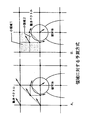
図9に16×16画素の単位領域を複数の三角形により分割した領域分割例を示す。図8に示すような被写体をアフィン変換による動き補償フレーム間予測方式を用いて予測する場合、図8−Aのように領域分割を5分割してもよいが、図8−Bに示すように、領域を斜め方向に4分割する分割方式をとると、予測処理の際に必要となる動きベクトルが7つから5つに減少することが分かる。 FIG. 9 shows an example of area division in which a unit area of 16 × 16 pixels is divided by a plurality of triangles. When a subject as shown in FIG. 8 is predicted using a motion compensation interframe prediction method based on affine transformation, the area may be divided into five as shown in FIG. 8-A, but as shown in FIG. 8-B. It can be seen that the motion vector required for the prediction process is reduced from seven to five when the division method of dividing the region into four in the diagonal direction is adopted.
上記のような分割数の少ない場合、例えば領域を斜め方向に2分割(図9において、“1,2”で示す分割方式)あるいは4分割(図9において、“27”で示す分割方式)する分割方式のように分割数の少ない場合でも、上記小領域毎に異なる予測方式を用いて複数の予測画像を生成する方式と組み合わせることにより、より動きベクトルなどのサイド情報が少なくても、予測効率を十分に上げることができる。 When the number of divisions is small as described above, for example, the region is divided into two diagonally (a division method indicated by “1, 2” in FIG. 9) or four divisions (a division method indicated by “27” in FIG. 9). Even when the number of divisions is small, as in the case of the division method, the prediction efficiency can be improved even when there is less side information such as motion vectors by combining with a method that generates multiple prediction images using different prediction methods for each small area. Can be raised sufficiently.
以上の説明から明らかなように、本発明によると、以下のような効果がある。 As is clear from the above description, the present invention has the following effects.
(1) 動き補償フレーム間予測処理の際に、可変サイズの小領域毎に異なる予測方式を用いて複数の予測画像を生成し、出力する予測部と、予測部からの複数の予測画像より最適な領域サイズおよび予測方式を決定し、領域情報、予測モード情報、動きベクトルなどから成るサイド情報と予測画像を出力する領域予測決定部と、領域予測決定部から出力される上記サイド情報を符号化するサイド情報符号化部を具備することで、複数の動き補償フレーム間予測方式の中で、動きベクトルなどのサイド情報量、もしくは、予測誤差が最も少なくなる予測方式を用いることが可能となる。 (1) In motion compensation inter-frame prediction processing, a prediction unit that generates and outputs a plurality of prediction images using different prediction methods for each small region of variable size, and a prediction unit that is more optimal than a plurality of prediction images from the prediction unit Region size and prediction method are determined, side information including region information, prediction mode information, motion vectors, and the like, a region prediction determination unit that outputs a prediction image, and the side information output from the region prediction determination unit are encoded By including the side information encoding unit that performs this, it is possible to use a prediction method that minimizes the amount of side information such as motion vectors or the prediction error among a plurality of motion compensation inter-frame prediction methods.
(2) 動き補償フレーム間予測処理の際に、符号化の単位となる領域、または前記単位領域を更に細かく分割した小領域毎に異なる予測方式を用いて複数の予測画像を生成し、出力する予測部と、予測部からの複数の予測画像より処理単位が単位領域または単位領域を更に分割した小領域であるかの情報(領域情報)および予測方式を決定し、領域情報、予測モード情報、動きベクトルなどから成るサイド情報と予測画像を出力する領域予測決定部と、領域予測決定部から出力される上記サイド情報を符号化するサイド情報符号化部を具備することで、複数の動き補償フレーム間予測方式の中で、動きベクトルなどのサイド情報量、もしくは、予測誤差が最も少なくなる予測方式を用いることが可能となる。 (2) In motion compensation inter-frame prediction processing, a plurality of prediction images are generated and output using different prediction methods for each region that is a unit of encoding or each small region obtained by further dividing the unit region. A prediction unit and information (region information) on whether the processing unit is a unit region or a small region obtained by further dividing the unit region from a plurality of prediction images from the prediction unit and a prediction method are determined, region information, prediction mode information, A plurality of motion compensation frames are provided by including a region prediction determination unit that outputs side information including a motion vector and the like and a predicted image, and a side information encoding unit that encodes the side information output from the region prediction determination unit. Among the inter prediction methods, a side information amount such as a motion vector or a prediction method with the smallest prediction error can be used.
(3) 動き補償フレーム間予測処理の際に、可変サイズの小領域毎にブロック移動(オーバーラップ動き補償)、アフィン変換、双線形変換、バックグラウンド予測などの予測方式を用いて複数の予測画像を生成し、出力する予測部と、予測部からの複数の予測画像より最適な領域サイズおよび予測方式を決定し、領域情報、予測モード情報、動きベクトルなどから成るサイド情報と予測画像を出力する領域予測決定部と、領域予測決定部から出力される上記サイド情報を符号化するサイド情報符号化部を具備することで、複数の動き補償フレーム間予測方式の中で、動きベクトルなどのサイド情報量、もしくは、予測誤差が最も少なくなる予測方式を用いることが可能となる。 (3) In motion compensation inter-frame prediction processing, a plurality of prediction images are used by using prediction methods such as block movement (overlapping motion compensation), affine transformation, bilinear transformation, and background prediction for each small region of variable size. Is determined and an optimal region size and prediction method is determined from a plurality of prediction images from the prediction unit, and side information and prediction images including region information, prediction mode information, motion vectors, and the like are output. By including a region prediction determination unit and a side information encoding unit that encodes the side information output from the region prediction determination unit, side information such as a motion vector in a plurality of motion compensation interframe prediction methods It is possible to use a prediction method that minimizes the amount or the prediction error.
(4) 動き補償フレーム間予測処理の際に、符号化の単位となる領域を斜め方向に2分割もしくは4分割した小領域毎にアフィン変換による予測を用いて予測画像を生成し、出力する予測部を具備することで、従来では不可能であった被写体の形状・大きさ・位置に対応し、動きベクトルなどのサイド情報、もしくは、予測誤差を減少させることが可能となる。 (4) Prediction that generates and outputs a prediction image using prediction based on affine transformation for each small region obtained by dividing an area that is a unit of coding into two or four in an oblique direction during motion compensation interframe prediction processing By providing the unit, it is possible to reduce side information such as a motion vector or a prediction error corresponding to the shape, size, and position of the subject, which has been impossible in the past.
(5) 動き補償フレーム間予測処理の際に、符号化の単位となる領域を斜め方向に2分割もしくは4分割した小領域毎にアフィン変換による予測を用いて予測画像を生成し、出力する予測部を具備することで、複数の動き補償フレーム間予測方式の中で、動きベクトルなどのサイド情報量、もしくは、予測誤差が最も少なくなる予測方式を用いること、および、従来では不可能であった被写体の形状・大きさ・位置に対応し、動きベクトルなどのサイド情報、もしくは、予測誤差を減少させることが可能となる。 (5) Prediction that generates and outputs a prediction image using prediction based on affine transformation for each small region obtained by dividing a region as a unit of coding into two or four in a diagonal direction during motion compensation interframe prediction processing By using this unit, it is impossible to use a prediction method that minimizes the side information amount such as a motion vector or a prediction error among a plurality of motion compensation inter-frame prediction methods. Corresponding to the shape, size, and position of the subject, side information such as motion vectors or prediction errors can be reduced.
(6) 符号化サイド情報を復号し、領域情報、予測モード情報、動きベクトルなどから成るサイド情報を復号し、出力するサイド情報符号化部と、動き補償フレーム間予測処理の際に、可変サイズの小領域毎に異なる予測方式を用いて複数の予測画像を生成し、出力する予測部と、サイド情報復号化部からの指示に従って予測部からの複数の予測画像の中で最適な予測画像を生成し、予測画像を出力する領域予測選択部を具備することで、複数の動き補償フレーム間予測方式の中で、動きベクトルなどのサイド情報量、もしくは、予測誤差が最も少なくなる予測方式を用いることが可能となる。 (6) Decode encoded side information, decode side information composed of region information, prediction mode information, motion vector, and the like, and output the side information encoding unit and variable size during motion compensation inter-frame prediction processing A prediction unit that generates and outputs a plurality of prediction images using different prediction methods for each of the small regions, and an optimal prediction image among the plurality of prediction images from the prediction unit according to an instruction from the side information decoding unit By including a region prediction selection unit that generates and outputs a predicted image, a prediction method that minimizes side information amount such as a motion vector or a prediction error is used among a plurality of motion compensation interframe prediction methods. It becomes possible.
(7) 符号化サイド情報を復号し、領域情報、予測モード情報、動きベクトルなどから成るサイド情報を復号し、出力するサイド情報符号化部と、動き補償フレーム間予測処理の際に、復号化の単位となる領域、または前記単位領域を更に細かく分割した小領域毎に異なる予測方式を用いて複数の予測画像を生成し、出力する予測部と、サイド情報復号化部からの指示に従って予測部からの複数の予測画像の中で最適な予測画像を生成し、予測画像を出力する領域予測選択部を具備することで、複数の動き補償フレーム間予測方式の中で、動きベクトルなどのサイド情報量、もしくは、予測誤差が最も少なくなる予測方式を用いることが可能となる。 (7) Decoding encoded side information, decoding side information consisting of region information, prediction mode information, motion vectors, etc., and outputting the decoded side information encoding unit and a motion compensation inter-frame prediction process A prediction unit that generates and outputs a plurality of prediction images using a different prediction method for each region that is a unit of the image, or for each small region obtained by further finely dividing the unit region, and a prediction unit according to an instruction from the side information decoding unit Side information such as motion vectors in a plurality of motion compensation inter-frame prediction schemes by generating an optimal prediction image among a plurality of prediction images from and generating a region prediction selection unit that outputs the prediction image It is possible to use a prediction method that minimizes the amount or the prediction error.
(8) 符号化サイド情報を復号し、領域情報、予測モード情報、動きベクトルなどから成るサイド情報を復号し、出力するサイド情報符号化部と、動き補償フレーム間予測処理の際に、復号化の単位となる領域、または前記単位領域を更に細かく分割した小領域毎にブロック移動(オーバーラップ動き補償)、アフィン変換、双線形変換、バックグラウンド予測などの予測方式を用いて複数の予測画像を生成し、出力する予測部と、サイド情報復号化部からの指示に従って予測部からの複数の予測画像の中で最適な予測画像を生成し、予測画像を出力する領域予測選択部を具備することで、複数の動き補償フレーム間予測方式の中で、動きベクトルなどのサイド情報量、もしくは、予測誤差が最も少なくなる予測方式を用いることが可能となる。 (8) Decoding encoded side information, decoding side information consisting of region information, prediction mode information, motion vectors, etc., and outputting the decoded side information encoding unit and a motion compensation inter-frame prediction process A plurality of prediction images using a prediction method such as block movement (overlap motion compensation), affine transformation, bilinear transformation, and background prediction for each region that is a unit of or a small region obtained by further finely dividing the unit region A prediction unit that generates and outputs, and an area prediction selection unit that generates an optimal prediction image among a plurality of prediction images from the prediction unit according to an instruction from the side information decoding unit and outputs the prediction image Therefore, among a plurality of motion compensation inter-frame prediction methods, it is possible to use a prediction method that minimizes side information amount such as a motion vector or a prediction error. .
(9) 動き補償フレーム間予測処理の際に、復号化処理の単位となる領域を斜め方向に2分割もしくは4分割した小領域毎にアフィン変換による予測を用いて予測画像を生成し、出力する予測部を具備することで、従来では不可能であった被写体の形状・大きさ・位置に対応し、動きベクトルなどのサイド情報、もしくは、予測誤差を減少させることが可能となる。 (9) At the time of motion compensation inter-frame prediction processing, a prediction image is generated and output using prediction by affine transformation for each small region obtained by dividing a region that is a unit of decoding processing into two or four in an oblique direction. By including the prediction unit, it is possible to reduce side information such as a motion vector or prediction error corresponding to the shape, size, and position of the subject, which has been impossible in the past.
(10) 動き補償フレーム間予測処理の際に、復号化処理の単位となる領域を斜め方向に2分割もしくは4分割した小領域毎にアフィン変換による予測を用いて予測画像を生成し、出力する予測部を具備することで、複数の動き補償フレーム間予測方式の中で、動きベクトルなどのサイド情報量、もしくは、予測誤差が最も少なくなる予測方式を用いること、および、従来では不可能であった被写体の形状・大きさ・位置に対応し、動きベクトルなどのサイド情報、もしくは、予測誤差を減少させることが可能となる。 (10) At the time of motion compensation inter-frame prediction processing, a prediction image is generated and output by using prediction based on affine transformation for each small region obtained by dividing a region that is a unit of decoding processing into two or four in an oblique direction. By including a prediction unit, it is impossible to use a prediction method that minimizes the amount of side information such as a motion vector or a prediction error among a plurality of motion compensation inter-frame prediction methods. The side information such as a motion vector or the prediction error can be reduced corresponding to the shape, size, and position of the subject.
11 減算部
12 画像符号化部
13 符号化制御部
14 画像復号化部
15 加算部
16 フレームメモリ部
17 動き補償フレーム間予測部
21 画像復号化部
DESCRIPTION OF
Claims (2)
既に復号化された映像信号を記憶しておくためのフレームメモリと、
予測モード情報および動きベクトルを含むサイド情報を復号するサイド情報復号化部と、
画像フレームを複数の処理領域に分割し、前記動きベクトルを用いて前記処理領域毎に複数の動き補償フレーム間予測方式により、前記フレームメモリに記憶された映像信号から前記予測モード情報に応じて予測画像を生成する予測部と
を備え、前記予測部は、
前記処理領域に対し、ブロック移動による予測方式を用いて前記予測画像を生成する第1の予測モードと、
前記処理領域に対し、アフィン変換による予測方式を用いて前記予測画像を生成する第2の予測モードと、
を有し、
所定の処理領域において前記第1の予測モードが用いられ、前記所定の処理領域に隣接する処理領域において前記第2の予測モードが用いられた場合に、前記隣接する処理領域の動きベクトルを用いることによって、前記所定の処理領域の動きベクトルを少ない情報量で復号することを特徴とする動画像復号化装置。 A video decoding device that restores an image from a prediction image obtained by performing adaptive motion compensation inter-frame prediction and decoded prediction error information,
A frame memory for storing already decoded video signals;
A side information decoding unit that decodes side information including prediction mode information and motion vectors;
An image frame is divided into a plurality of processing regions, and prediction is performed according to the prediction mode information from the video signal stored in the frame memory by using a plurality of motion compensation interframe prediction methods for each processing region using the motion vector. A prediction unit that generates an image, the prediction unit,
A first prediction mode for generating the predicted image using a prediction method based on block movement for the processing region;
A second prediction mode for generating the predicted image using a prediction method based on affine transformation for the processing region;
Have
When the first prediction mode is used in a predetermined processing region and the second prediction mode is used in a processing region adjacent to the predetermined processing region, the motion vector of the adjacent processing region is used. Thus, the moving picture decoding apparatus characterized in that the motion vector of the predetermined processing area is decoded with a small amount of information.
画像フレームの動きベクトルを復号化する動きベクトル復号化部と、A motion vector decoding unit for decoding a motion vector of an image frame;
前記画像フレームを複数の領域に分割した領域毎に、前記動きベクトルと前記複数の予測方式のそれぞれに対応する予測画像を生成する予測部と、A prediction unit that generates a prediction image corresponding to each of the motion vector and the plurality of prediction methods for each region obtained by dividing the image frame into a plurality of regions;
前記複数の予測方式から一の予測方式を選択する情報および前記動きベクトルを示す情報を復号化するサイド情報復号化部とを備え、A side information decoding unit that decodes information for selecting one prediction method from the plurality of prediction methods and information indicating the motion vector;
前記符号化されたデータは、前記動画像符号化装置に入力された画像フレームを複数の領域に分割した領域の動きベクトルと、該領域に対して複数の予測方式から選択した一の予測方式を示すサイド情報とを含み、The encoded data includes a motion vector of a region obtained by dividing an image frame input to the video encoding device into a plurality of regions, and one prediction method selected from a plurality of prediction methods for the region. Including side information to show,
前記サイド情報は、前記動画像符号化装置において、符号化対象領域に隣接する領域に対し該符号化対象領域とは異なる予測方式が決定された場合に、該隣接領域の動きベクトルを用いることによって、符号化対象領域の動きベクトルに要するサイド情報量を少なくしたものであり、The side information is obtained by using a motion vector of the adjacent region when a prediction method different from the encoding target region is determined for the region adjacent to the encoding target region in the moving image encoding device. , The amount of side information required for the motion vector of the encoding target area is reduced,
前記サイド情報復号化部は、復号化対象領域に隣接する領域に対し該復号化対象領域とは異なる予測方式が決定された場合に、該隣接領域の動きベクトルを用いることによって、復号化対象領域の動きベクトルを復号化することを特徴とする動画像復号化装置。When the prediction method different from the decoding target area is determined for the area adjacent to the decoding target area, the side information decoding unit uses the motion vector of the adjacent area to determine the decoding target area. A moving picture decoding apparatus characterized by decoding a motion vector of the video.
Priority Applications (1)
| Application Number | Priority Date | Filing Date | Title |
|---|---|---|---|
| JP2007027104A JP4427553B2 (en) | 2007-02-06 | 2007-02-06 | Video decoding device |
Applications Claiming Priority (1)
| Application Number | Priority Date | Filing Date | Title |
|---|---|---|---|
| JP2007027104A JP4427553B2 (en) | 2007-02-06 | 2007-02-06 | Video decoding device |
Related Parent Applications (1)
| Application Number | Title | Priority Date | Filing Date |
|---|---|---|---|
| JP2005086858A Division JP4134078B2 (en) | 2005-03-24 | 2005-03-24 | Video decoding device |
Publications (3)
| Publication Number | Publication Date |
|---|---|
| JP2007181226A JP2007181226A (en) | 2007-07-12 |
| JP2007181226A5 JP2007181226A5 (en) | 2009-05-07 |
| JP4427553B2 true JP4427553B2 (en) | 2010-03-10 |
Family
ID=38305824
Family Applications (1)
| Application Number | Title | Priority Date | Filing Date |
|---|---|---|---|
| JP2007027104A Expired - Lifetime JP4427553B2 (en) | 2007-02-06 | 2007-02-06 | Video decoding device |
Country Status (1)
| Country | Link |
|---|---|
| JP (1) | JP4427553B2 (en) |
Cited By (1)
| Publication number | Priority date | Publication date | Assignee | Title |
|---|---|---|---|---|
| WO2018131986A1 (en) * | 2017-01-16 | 2018-07-19 | 세종대학교 산학협력단 | Image encoding/decoding method and device |
Families Citing this family (3)
| Publication number | Priority date | Publication date | Assignee | Title |
|---|---|---|---|---|
| KR102121558B1 (en) | 2013-03-15 | 2020-06-10 | 삼성전자주식회사 | Method of stabilizing video image, post-processing device and video encoder including the same |
| CN109716763A (en) | 2016-09-26 | 2019-05-03 | 索尼公司 | Encoding device, coding method, decoding device, coding/decoding method, sending device and receiving device |
| JP7401246B2 (en) | 2019-10-08 | 2023-12-19 | キヤノン株式会社 | Imaging device, method of controlling the imaging device, and program |
-
2007
- 2007-02-06 JP JP2007027104A patent/JP4427553B2/en not_active Expired - Lifetime
Cited By (1)
| Publication number | Priority date | Publication date | Assignee | Title |
|---|---|---|---|---|
| WO2018131986A1 (en) * | 2017-01-16 | 2018-07-19 | 세종대학교 산학협력단 | Image encoding/decoding method and device |
Also Published As
| Publication number | Publication date |
|---|---|
| JP2007181226A (en) | 2007-07-12 |
Similar Documents
| Publication | Publication Date | Title |
|---|---|---|
| CN108848376B (en) | Video encoding method, video decoding method, video encoding device, video decoding device and computer equipment | |
| CN108769682B (en) | Video encoding method, video decoding method, video encoding apparatus, video decoding apparatus, computer device, and storage medium | |
| JP5081305B2 (en) | Method and apparatus for interframe predictive coding | |
| JP3277111B2 (en) | Video encoding device and video decoding device | |
| JP4501631B2 (en) | Image coding apparatus and method, computer program for image coding apparatus, and portable terminal | |
| JP2008154015A (en) | Decoding method and coding method | |
| CN104320664A (en) | Image processing device and method | |
| JP2006279573A (en) | Encoder and encoding method, and decoder and decoding method | |
| JP3637996B2 (en) | Video encoding / decoding device using motion-compensated interframe prediction method capable of region integration | |
| JP5560009B2 (en) | Video encoding device | |
| WO2012098845A1 (en) | Image encoding method, image encoding device, image decoding method, and image decoding device | |
| US20090028241A1 (en) | Device and method of coding moving image and device and method of decoding moving image | |
| JP2012080151A (en) | Method and apparatus for moving image encoding and moving image decoding using geometry-transformed/motion-compensated prediction | |
| JP4427553B2 (en) | Video decoding device | |
| JPH1093975A (en) | Motion compensation inter-frame predicting method in moving image encoder | |
| JP5571542B2 (en) | Video encoding method and video decoding method | |
| JP2914448B2 (en) | Motion vector prediction encoding method and motion vector decoding method, prediction encoding device and decoding device, and recording medium recording motion vector prediction encoding program and decoding program | |
| JP2006100871A (en) | Coder, coding method, program of coding method, and recording medium with the program recorded thereon | |
| JP3746708B2 (en) | Video encoding device | |
| JP5938424B2 (en) | Method for reconstructing and encoding image blocks | |
| KR100926752B1 (en) | Fine Motion Estimation Method and Apparatus for Video Coding | |
| JP2001224036A (en) | Moving picture coder | |
| JP4134078B2 (en) | Video decoding device | |
| JP5067471B2 (en) | Decoding method, decoding apparatus, and program | |
| JP3277116B2 (en) | Video encoding device and video decoding device |
Legal Events
| Date | Code | Title | Description |
|---|---|---|---|
| A521 | Written amendment |
Free format text: JAPANESE INTERMEDIATE CODE: A523 Effective date: 20090323 |
|
| TRDD | Decision of grant or rejection written | ||
| A01 | Written decision to grant a patent or to grant a registration (utility model) |
Free format text: JAPANESE INTERMEDIATE CODE: A01 Effective date: 20091208 |
|
| A01 | Written decision to grant a patent or to grant a registration (utility model) |
Free format text: JAPANESE INTERMEDIATE CODE: A01 |
|
| A61 | First payment of annual fees (during grant procedure) |
Free format text: JAPANESE INTERMEDIATE CODE: A61 Effective date: 20091214 |
|
| R150 | Certificate of patent or registration of utility model |
Free format text: JAPANESE INTERMEDIATE CODE: R150 |
|
| FPAY | Renewal fee payment (event date is renewal date of database) |
Free format text: PAYMENT UNTIL: 20121218 Year of fee payment: 3 |
|
| FPAY | Renewal fee payment (event date is renewal date of database) |
Free format text: PAYMENT UNTIL: 20121218 Year of fee payment: 3 |
|
| R250 | Receipt of annual fees |
Free format text: JAPANESE INTERMEDIATE CODE: R250 |
|
| EXPY | Cancellation because of completion of term |