JP7401246B2 - Imaging device, method of controlling the imaging device, and program - Google Patents
Imaging device, method of controlling the imaging device, and program Download PDFInfo
- Publication number
- JP7401246B2 JP7401246B2 JP2019185391A JP2019185391A JP7401246B2 JP 7401246 B2 JP7401246 B2 JP 7401246B2 JP 2019185391 A JP2019185391 A JP 2019185391A JP 2019185391 A JP2019185391 A JP 2019185391A JP 7401246 B2 JP7401246 B2 JP 7401246B2
- Authority
- JP
- Japan
- Prior art keywords
- image
- imaging
- parameter
- predicted
- recognition
- Prior art date
- Legal status (The legal status is an assumption and is not a legal conclusion. Google has not performed a legal analysis and makes no representation as to the accuracy of the status listed.)
- Active
Links
- 238000003384 imaging method Methods 0.000 title claims description 209
- 238000000034 method Methods 0.000 title claims description 146
- 238000012545 processing Methods 0.000 claims description 132
- 238000013528 artificial neural network Methods 0.000 claims description 39
- 239000013598 vector Substances 0.000 description 34
- 238000004364 calculation method Methods 0.000 description 31
- 230000006870 function Effects 0.000 description 20
- 238000010586 diagram Methods 0.000 description 18
- 230000009191 jumping Effects 0.000 description 13
- 239000011159 matrix material Substances 0.000 description 11
- 238000013527 convolutional neural network Methods 0.000 description 10
- 238000003672 processing method Methods 0.000 description 4
- 230000015654 memory Effects 0.000 description 3
- 238000012549 training Methods 0.000 description 3
- 238000012546 transfer Methods 0.000 description 3
- 210000000746 body region Anatomy 0.000 description 2
- 238000006243 chemical reaction Methods 0.000 description 2
- 238000001514 detection method Methods 0.000 description 2
- 230000003287 optical effect Effects 0.000 description 2
- 230000011218 segmentation Effects 0.000 description 2
- 206010000117 Abnormal behaviour Diseases 0.000 description 1
- 238000013459 approach Methods 0.000 description 1
- 230000006399 behavior Effects 0.000 description 1
- 230000000295 complement effect Effects 0.000 description 1
- 230000009977 dual effect Effects 0.000 description 1
- 238000000605 extraction Methods 0.000 description 1
- 238000010801 machine learning Methods 0.000 description 1
- 229910044991 metal oxide Inorganic materials 0.000 description 1
- 150000004706 metal oxides Chemical class 0.000 description 1
- 238000012986 modification Methods 0.000 description 1
- 230000004048 modification Effects 0.000 description 1
- 238000012806 monitoring device Methods 0.000 description 1
- 238000001556 precipitation Methods 0.000 description 1
- 239000004065 semiconductor Substances 0.000 description 1
- 230000006403 short-term memory Effects 0.000 description 1
Images


Landscapes
- Image Analysis (AREA)
- Exposure Control For Cameras (AREA)
- Studio Devices (AREA)
- Compression Or Coding Systems Of Tv Signals (AREA)
Description
本発明は、撮像時に用いられる撮像パラメータの制御技術に関する。 The present invention relates to a technique for controlling imaging parameters used during imaging.
撮像装置において、所望の画像を取得することを可能とする撮像パラメータを制御する技術として、画像に対して認識処理を実行し、得られた認識結果を基にして撮像パラメータを制御する技術が広く提案されている。特許文献1には、監視装置等のカメラが撮像した画像を用いた人物の顔認識結果を基に、その人物の顔を確認し易くするようにカメラの上下方向、水平方向、回転方向等の撮影方向、及び画角の少なくとも一つの撮像パラメータを決定する技術が開示されている。
As a technology for controlling imaging parameters that enables acquisition of a desired image in an imaging device, a technology that executes recognition processing on an image and controls imaging parameters based on the obtained recognition results is widely used. Proposed.
前述した画像認識結果に基づく撮像パラメータ制御技術の場合、認識処理を適用する対象となる画像は既に取得済みの画像である。このため、画像認識結果を基に撮像パラメータを制御した場合、当該撮像パラメータを反映した上で新たに取得した画像において、認識対象物の画像上の位置および画素レベルの輝度データは、既に変化している可能性が有る。この場合、顔画像のような所望の画像を取得するために制御した撮像パラメータの値は、その撮像パラメータを基に新たに撮像される画像に対して適当でない値となってしまってしまうことが有り得る。つまり、その撮像パラメータは、新たに撮像される画像に対して適合していない可能性がある。 In the case of the imaging parameter control technique based on the image recognition results described above, the image to which recognition processing is applied is an image that has already been acquired. Therefore, when the imaging parameters are controlled based on the image recognition results, the position of the recognition target on the image and the pixel-level brightness data have already changed in the newly acquired image after reflecting the imaging parameters. There is a possibility that In this case, the values of the imaging parameters controlled to obtain a desired image such as a face image may end up being inappropriate values for the newly captured image based on the imaging parameters. Possible. In other words, the imaging parameters may not be suitable for a newly captured image.
そこで、本発明は、撮像パラメータを基に撮像される画像に対して、より適合した撮像パラメータを決定可能にすることを目的とする。 Therefore, an object of the present invention is to make it possible to determine imaging parameters that are more suitable for an image that is captured based on the imaging parameters.
本発明の撮像装置は、画像の画素または領域毎に撮像パラメータを設定可能な撮像センサを備え、動く物体を撮像した画像を取得する撮像手段と、前記取得された画像を基に前記撮像手段によって、前記物体が動いた後に撮像される画像を予測した予測画像を生成する画像生成手段と、前記画像生成手段で生成された予測画像に対して画像認識処理を実行する画像認識手段と、前記画像認識処理によって得られる前記予測画像内の前記物体の位置に基づいて、前記画素または領域毎に前記撮像センサの前記撮像パラメータを決定するパラメータ決定手段と、前記決定した撮像パラメータを前記撮像センサに対して前記画素または領域毎に設定するパラメータ設定手段と、を有し、前記撮像手段は、前記パラメータ設定手段で設定されたパラメータに従って画像を取得することを特徴とする。 The imaging device of the present invention includes an imaging sensor capable of setting imaging parameters for each pixel or region of an image, an imaging means for acquiring an image of a moving object, and an imaging means for acquiring an image of a moving object based on the acquired image. , an image generation unit that generates a predicted image that predicts an image that will be captured after the object moves ; an image recognition unit that performs image recognition processing on the predicted image generated by the image generation unit ; parameter determining means for determining the imaging parameters of the imaging sensor for each pixel or region based on the position of the object in the predicted image obtained by recognition processing; and parameter setting means for setting each pixel or region , and the imaging means acquires an image according to the parameters set by the parameter setting means .
本発明によれば、撮像パラメータを基に撮像される画像に対して、より適合した撮像パラメータを決定することができる。 According to the present invention, it is possible to determine imaging parameters that are more suitable for an image that is captured based on the imaging parameters.
以下、本発明の実施形態を、添付の図面に基づいて詳細に説明する。なお、以下の実施形態において示す構成は一例にすぎず、本発明は図示された構成に限定されるものではない。
<実施形態1>
まず、本発明に係る実施形態1について説明する。図1は、本実施形態に係る撮像装置の構成例を示すブロック図である。
Hereinafter, embodiments of the present invention will be described in detail based on the accompanying drawings. Note that the configurations shown in the following embodiments are merely examples, and the present invention is not limited to the illustrated configurations.
<
First,
図1に示すように、本実施形態の撮像装置は、画像センサ部10、画像生成部20、画像認識部30、パラメータ決定部40、パラメータ設定部50、RAM80、画像バス120、およびCPUバス170を有する。さらに撮像装置は、ブリッジ130、DMAC(Direct Memory Access Controller)70、CPU(Central Processing Unit)140、ROM150、及びRAM160を有している。画像センサ部10、画像生成部20、画像認識部30、パラメータ決定部40、パラメータ設定部50及びDMAC70は、画像バス120を介して互いに接続されている。またCPU140、ROM150及びRAM160は、CPUバス170を介して互いに接続されている。ブリッジ130は、画像バス120とCPUバス170との間のデータ転送を可能にする。
As shown in FIG. 1, the imaging apparatus of this embodiment includes an
画像センサ部10は、光学系、撮像センサ、撮像センサを制御するドライバー回路、撮像センサにて取得された撮像信号をデジタル信号に変換するA/D変換回路、および、デジタル信号に変換された撮像信号を画像として現像する現像回路等を備えている。撮像センサは、例えばCMOS(Complementary Metal Oxide Semiconductor)センサからなる。
The
ここで、画像センサ部10は、撮像センサの動作特性を決定する撮像パラメータを制御する機能を有する。撮像パラメータを制御する機能は、画像センサ部10内の例えばドライバー回路が担っている。撮像パラメータは、露光パラメータ、フォーカスパラメータ、ダイナックレンジパラメータ、ゲインパラメータ、フレームレートパラメータ、撮像領域パラメータ、解像度パラメータ等からなる。露光パラメータは、撮像センサにおける露光時間等を制御するパラメータである。フォーカスパラメータは、撮像センサ上でフォーカス用の画素等の動作を制御するパラメータである。ゲインパラメータは、撮像センサにより撮像された信号のゲインを制御するパラメータである。フレームレートパラメータは、撮像センサにおける撮像時のフレームレートを制御するパラメータである。撮像領域パラメータは、撮像センサ上で撮像する領域を制御するパラメータである。解像度パラメータは、撮像センサの解像度を制御するパラメータである。撮像パラメータによる制御機能の具体例については後述する。
Here, the
画像生成部20は、画像センサ部10により取得された少なくとも1枚の画像データから、将来の画像として予測される予測画像を生成する機能を有する。画像生成部20における予測画像生成機能の詳細については後述する。
画像認識部30は、画像生成部20によって生成された予測画像に対して所定の画像認識処理を実行する機能を有する。なお実施形態1では、画像認識部30が画像認識処理として領域分割処理を実行する場合に関して説明する。画像認識部30における画像認識処理機能(領域分割処理機能)の詳細については後述する。
The
The
パラメータ決定部40は、画像認識部30による認識結果を基に、画像センサ部10の撮像センサを制御するための撮像パラメータの種類およびその値を決定する。パラメータ決定部40における撮像パラメータ決定機能の詳細については後述する。
パラメータ設定部50は、パラメータ決定部40により決定された撮像パラメータの値を、画像センサ部10に対して設定する。パラメータ設定部50における撮像パラメータ設定機能の詳細については後述する。
The
The
DMAC70は、画像センサ部10、画像生成部20、画像認識部30、パラメータ決定部40、パラメータ設定部50、及びCPUバス170との間のデータ転送を司る。
ROM(Read Only Memory)150は、CPU140が実行するプログラム、CPU140の動作を規定する命令、パラメータデータ、重み係数等を格納している。
CPU140は、ROM150から、それらプログラムや命令、パラメータデータ等を読み出しつつ、当該撮像装置の全体の動作を制御したり、様々な演算を行ったりする。なお、CPU140はブリッジ130を介して画像バス120上のRAM80にアクセスすることも可能である。
RAM160は、CPU140が撮像装置を制御等する際に、当該CPU140の作業領域として使用される。
The DMAC 70 controls data transfer between the
The ROM (Read Only Memory) 150 stores programs executed by the
The
The
次に、図1に示した構成を有する撮像装置の動作について説明する。
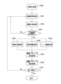
図2は、本実施形態に係る撮像装置の動作を示すフローチャートである。なお図2に示した処理フロー全体の制御は、事前に設定されたプログラムに基づいてCPU140により実行される。
Next, the operation of the imaging apparatus having the configuration shown in FIG. 1 will be described.
FIG. 2 is a flowchart showing the operation of the imaging device according to this embodiment. Note that control of the entire processing flow shown in FIG. 2 is executed by the
先ずステップS180において、CPU140は、撮像処理の開始に先立ち、撮像装置における各種初期化処理を実行する。例えば、CPU140は、画像認識部30および画像生成部20の動作に必要な重み係数をROM150からRAM160に転送すると共に、画像認識部30および画像生成部20の動作を定義する為の各種レジスタ設定を行う。具体的には、CPU140は、画像認識部30および画像生成部20内の制御部に存在する複数のレジスタに所定の値を設定する。同様に、CPU140は、画像センサ部10に対しても動作に必要な値を書き込む。この時、画像センサ部10の撮像センサを制御するための撮像パラメータの値としては、事前に決定された所定の初期値またはユーザが設定した初期値が設定される。
First, in step S180, the
次にステップS181において、画像センサ部10は、撮像処理を実行して撮像画像データを取得する。
続いてステップS182において、画像生成部20は、画像センサ部10にて取得された画像データを内部のフレームバッファにフレーム単位で格納する。ここで、本実施形態の場合、画像生成部20は、5フレーム分の画像データが入力されてから、1フレーム分の予測画像の生成および出力を開始するものとする。このため、画像生成部20は、画像センサ部10からフレーム単位で画像データを取得し、ステップS183において予測画像の生成を開始するか判定する。画像生成部20は、5フレーム分の画像データを取得できた場合には、ステップS183において予測画像の生成を開始し、1フレーム分の予測画像を生成して出力する。一方、画像生成部20は、5フレーム分の画像データが取得できていない場合には、予測画像の生成を開始せずに、画像センサ部10によるステップS181の画像取得処理に戻す。なお本実施形態において、画像生成部20は、次のフレームの画像データを取得するまでの間に、既にフレームバッファに格納された画像データに対して、所定の処理(特徴抽出処理など、予測画像生成に必要な各種の処理)を実行するものとする。画像生成部20における予測画像生成処理の詳細については後述する。
Next, in step S181, the
Subsequently, in step S182, the
ステップS183で予測画像の生成処理が開始されて予測画像が生成されると、CPU140は、画像認識部30にて行われるステップS184に処理を進める。
ステップS184に進むと、画像認識部30は、画像生成部20で生成された予測画像を用いた画像認識処理を行う。本実施形態の場合、画像認識部30は、画像認識処理を実行し、画像生成部20で生成された予測画像を複数の領域に分割した分割領域の単位で画像認識結果を出力する。そして、画像認識部30は、画像認識処理の結果として、画像(予測画像)上における、分割領域の座標値(画像上の画素の位置を示す座標値)を出力する。
When the predicted image generation process is started in step S183 and the predicted image is generated, the
Proceeding to step S184, the
次にステップS185の撮像パラメータ決定処理として、パラメータ決定部40は、画像センサ部10の動作特性を決定する前述した撮像パラメータの値を決定する。本実施形態の場合、パラメータ決定部40は、ステップS184の画像認識処理による認識結果として算出された、画像上における分割領域の座標値の情報と、ステップS182の画像生成処理で生成された予測画像とに基づいて、撮像パラメータの値を決定する。撮像パラメータ値の決定方法の具体例については後述する。
Next, as an imaging parameter determination process in step S185, the
次にステップS186の撮像パラメータ設定処理として、パラメータ設定部50は、ステップS185で決定された撮像パラメータの値を、画像センサ部10に対して設定する。
ステップS186による撮像パラメータの設定が完了すると、CPU140は、ステップS187において終了通知の発行(例えばユーザによる終了指示に基づく、CPU140に対する割り込み信号)を確認する。CPU140は、終了通知が発行されていない場合には撮像装置の処理をステップS181の画像取得処理に戻して、ステップS181以降の処理を継続させる。一方、CPU140は、終了通知の発行を確認すると、図2のフローチャートの処理を終了する。
Next, as imaging parameter setting processing in step S186, the
When the setting of the imaging parameters in step S186 is completed, the
なお前述の説明では、画像生成部20は、5フレーム分の画像データが入力されてから、1フレーム分の予測画像の出力を開始するものとしたが、この例に限定されるものではない。例えば、画像生成部20は、過去の任意のnフレーム分の画像データが入力されてから1フレーム分の予測画像の出力を開始するものであっても良い。この場合の過去の任意のnフレーム分の"n"は1以上の値である。例えば"n"が1である場合、画像生成部20は過去の1フレーム分の画像データを基に、予測画像を生成することになる。また本実施形態において、画像生成部20は、1フレーム分の予測画像を出力するものとしたが、複数フレーム分の予測画像を生成して出力するものであっても良い。複数フレーム分の予測画像は、時系列順の複数のフレームの予測画像であっても良いし、同フレーム時間に相当する複数の予測画像であっても良い。同フレーム時間に相当する複数の予測画像は、例えば撮像で取得された画像から予測される確率順(例えば予測される確率が高い順)の複数パターンの予測画像であっても良い。
Note that in the above description, the
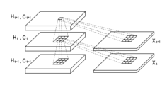
次に、前述した画像生成部20で実行される画像生成処理に関して、図3を用いて詳細に説明する。図3は、予測画像を生成する画像生成処理を実現するニューラルネットワーク(以下、NNと表記する)の構成を模式的に示した図である。
なお、本実施形態で用いるNN(ニューラルネットワーク)に関しては、下記の参考文献1において詳細に開示されているものを適用可能であり、画像生成部20は、当該NNを適用して、複数フレームの画像データを基に予測画像を生成する機能を有する。本実施形態では、画像生成処理の実現方法として、参考文献1に開示されている手法を適用することを想定しているが、この手法に限定されるものではない。例えば下記の参考文献2に開示されるような手法が用いられてもよい。また本実施形態における画像生成処理の実現方法は、それら参考文献1や参考文献2に開示された手法だけでなく、その他の手法を用いるものであっても構わない。
Next, the image generation process executed by the
Regarding the NN (neural network) used in this embodiment, the one disclosed in detail in
参考文献1:Xingjian Shi, Zhourong Chen, Hao Wang, Dit-Yan Yeung, "Convolutional LSTM Network: A Machine Learning Approach for Precipitation Nowcasting", arXiv 2015 Reference 1: Xingjian Shi, Zhourong Chen, Hao Wang, Dit-Yan Yeung, "Convolutional LSTM Network: A Machine Learning Approach for Precipitation Nowcasting", arXiv 2015
参考文献2:William Lotter, Gabriel Kreiman, David Cox, "Deep Predictive Coding Networks for Video Prediction and Unsupervised Learning", arXiv 2017 Reference 2: William Lotter, Gabriel Kreiman, David Cox, "Deep Predictive Coding Networks for Video Prediction and Unsupervised Learning", arXiv 2017
画像生成部20は、画像センサ部10から入力された画像データXtを、内部のフレームバッファに一旦格納した後、図3に示すように、畳み込みLSTMモジュールに入力する。畳み込みLSTMモジュールは、時系列データに対して、時系列情報を含んだ処理を実行するNNである。畳み込みLSTMモジュールは、広く利用されているLSTM(long short-term memory)を時系列画像データに拡張したものである。前述の参考文献1には、畳み込みLSTMに関して詳細に説明されている。
The
畳み込みLSTMにおける処理は、以下の式(1)で表される。前述したように、畳み込みLSTMは、時系列画像データを使用して事前に学習することにより、所望の出力を得ることが可能なNNある。本実施形態においては、式(1)に基づいて、過去の5フレーム分の時系列画像データX0~X4から次のフレームの予測画像X5を生成するように、事前に学習が行われる。 Processing in convolution LSTM is expressed by the following equation (1). As described above, convolutional LSTM is a neural network (NN) that can obtain a desired output by learning in advance using time-series image data. In this embodiment, learning is performed in advance to generate the predicted image X 5 of the next frame from the past five frames of time-series image data X 0 to X 4 based on equation (1). .

ここで、式(1)中の各記号が示す内容は以下の通りである。なお、アダマール積については式(1)中に記載している。
X:入力データ
C:セル出力データ
H:隠れ層の状態
i:入力ゲート
f:忘却ゲート
o:出力ゲート
t:時間(フレーム)
Wxo:入力荷重マトリクス(出力ゲート)
Who:状態荷重マトリクス(出力ゲート)
Wco:セル出力荷重マトリクス(出力ゲート)
bo:バイアス(出力ゲート)
Wxc:入力荷重マトリクス(セル出力)
Whc:状態荷重マトリクス(セル出力)
bc:バイアス(セル出力)
Wxf:入力荷重マトリクス(忘却ゲート)
Whf:状態荷重マトリクス(忘却ゲート)
Wcf:セル出力荷重マトリクス(忘却ゲート)
bf:バイアス(忘却ゲート)
Wxi:入力荷重マトリクス(入力ゲート)
Whi:状態荷重マトリクス(入力ゲート)
Wci:セル出力荷重マトリクス(入力ゲート)
bi:バイアス(入力ゲート)
*:畳み込み演算
Here, the contents indicated by each symbol in formula (1) are as follows. Note that the Hadamard product is described in equation (1).
X: Input data C: Cell output data H: Hidden layer state i: Input gate f: Forgetting gate o: Output gate t: Time (frame)
W xo : Input load matrix (output gate)
W ho : State load matrix (output gate)
W co : Cell output load matrix (output gate)
b o : Bias (output gate)
W xc : Input load matrix (cell output)
W hc : State weight matrix (cell output)
b c : Bias (cell output)
W xf : Input load matrix (forgetting gate)
W hf : state weight matrix (forgetting gate)
W cf : Cell output load matrix (forgetting gate)
b f : Bias (forgetting gate)
W xi : Input load matrix (input gate)
W hi : State weight matrix (input gate)
W ci : Cell output load matrix (input gate)
b i : Bias (input gate)
*: Convolution operation
本実施形態の画像生成部20は、前述したように畳み込みLSTMを用いて構成されているものとしたが、これに限るものではない。予測画像を生成する手法に関しては、前述の手法以外にも非特許文献2など様々な手法が提案されており、他の手法が用いられても構わない。
Although the
図3に示したNNの構成において、畳み込みLSTMは、過去の5フレーム分の画像を基にして1フレーム分の予測画像を出力する。なお図3の例においても、画像生成処理として、過去の任意のnフレーム分の画像を基にして1レーム分の予測画像を出力するものであっても良いし、複数フレーム分の予測画像を出力するものであっても良い。畳み込みLSTMによって生成された画像は、一旦フレームバッファに格納され、図2におけるステップS184の画像認識処理に入力される。 In the configuration of the NN shown in FIG. 3, the convolution LSTM outputs a predicted image for one frame based on images for five past frames. In the example of FIG. 3 as well, the image generation process may output a predicted image for one frame based on images for any n frames in the past, or may output a predicted image for multiple frames. It may be something that is output. The image generated by the convolution LSTM is temporarily stored in a frame buffer and input to the image recognition process in step S184 in FIG.
次に、前述した画像認識部30で実行されるステップS184の画像認識処理に関して、図4を用いて詳細に説明する。図4は、入力された予測画像に対して、所定の画像認識処理を実現するNNの構成例を模式的に示した図である。
図4に示すNNは、階層型畳み込みNN(ニューラルネットワーク)モジュール190と階層型逆畳み込みNNモジュール191とで構成され、各層は畳み込み演算素子401~408により構成されている。この図4に示したようなNNに関しては、下記の参考文献3に詳細に開示されているものである。画像認識部30は、図4のようなNNにより、入力された予測画像データに対して、画像内の物体毎の画像認識処理(認識結果として分割領域を得る処理)を実行する機能を有する。
Next, the image recognition process in step S184 executed by the
The NN shown in FIG. 4 is composed of a hierarchical convolutional NN (neural network)
参考文献3:Hyeonwoo Noh, Seunghoon Hong, Bohyung Han, "Learning Deconvolution Network for Semantic Segmentation", ICCV 2015 Reference 3: Hyeonwoo Noh, Seunghoon Hong, Bohyung Han, "Learning Deconvolution Network for Semantic Segmentation", ICCV 2015
画像認識部30は、入力された予測画像データを内部のフレームバッファに一旦格納した後、図4に示す階層型畳み込みNNモジュール190に入力し、更に階層型逆畳み込みNNモジュール191に入力する。階層型畳み込みNNモジュール190と階層型逆畳み込みNNモジュール191とから構成されるNNは、画像処理に広く利用されている。特に本実施形態のように、領域分割が適用される例は、参考文献3において詳細に説明されている。
The
階層型畳み込みNNモジュール190における処理は、以下の式(2)で表される。
The processing in the hierarchical
![]()
![]()
ここで式(2)中の各記号が示す内容は以下の通りである。
x:入力データ
y:出力データ
w:畳み込みフィルタ
v:畳み込みフィルタの高さ
h:畳み込みフィルタの幅
m:前段層特徴面インデックス
n:後段層特徴面インデックス
i:前段層演算位置y座標
j:前段層演算位置x座標
i':前段層演算位置y座標
j':後段層演算位置x座標
k:畳み込みフィルタy座標
l(t):畳み込みフィルタx座標
Here, the contents indicated by each symbol in formula (2) are as follows.
x: Input data y: Output data w: Convolution filter v: Height of convolution filter h: Width of convolution filter m: Previous layer feature surface index n: Later layer feature surface index i: Previous layer calculation position y-coordinate j: Previous layer Layer calculation position x-coordinate i': Previous layer calculation position y-coordinate j': Subsequent layer calculation position x-coordinate k: Convolution filter y-coordinate l(t): Convolution filter x-coordinate
また階層型逆畳み込みNNモジュール191は、式(3)で表される。
Furthermore, the hierarchical
![]()
![]()
ここで式(3)中の各記号が示す内容は以下の通りである。
x:入力データ(前段層特徴面にゼロ値を挿入して拡大したデータ)
y:出力データ
w:逆畳み込みフィルタ
v:逆畳み込みフィルタの高さ
h:逆畳み込みフィルタの幅
m:前段層特徴面インデックス
n:後段層特徴面インデックス
i:前段層演算位置y座標
j:前段層演算位置x座標
i':前段層演算位置y座標
j':後段層演算位置x座標
k:逆畳み込みフィルタy座標
l(t):逆畳み込みフィルタx座標
Here, the contents indicated by each symbol in formula (3) are as follows.
x: Input data (data expanded by inserting zero values into the feature plane of the previous layer)
y: Output data w: Deconvolution filter v: Height of deconvolution filter h: Width of deconvolution filter m: Previous layer feature surface index n: Later layer feature surface index i: Previous layer calculation position y-coordinate j: Previous layer Calculation position x-coordinate i': Previous layer calculation position y-coordinate j': Subsequent layer calculation position x-coordinate k: Deconvolution filter y-coordinate l(t): Deconvolution filter x-coordinate
本実施形態では、これら階層型畳み込みNNモジュール190と階層型逆畳み込みNNモジュール191から構成されるNNに対し、領域分割に関する教師データを有する画像データを用いた事前学習が行われることにより、所望の出力を得ることが可能となる。学習処理に関しては、一般的な学習手法を適用することが可能であり、詳細な学習手法に関する説明は省略する。
In this embodiment, the NN composed of the hierarchical
なお本実施形態における画像認識部30は、前述したように階層型畳み込みNNモジュール190と階層型逆畳み込みNNモジュール191とから構成されるNNを用いて構成するものとしたが、この例に限られるものではない。領域分割を伴う画像認識処理を実現する手法に関しては、これ以外にも参考文献3を含む様々な手法が提案されており、その他の手法を用いたものであっても構わない。
Although the
前述した図2のステップS184の画像認識処理において、画像認識部30は、入力された予測画像に対して領域分割処理を実行し、予測画像内の物体毎に定義される分割領域を認識結果として算出する処理を行う。具体的には、画像認識部30は、図5に示すように、予測画像500の中に含まれる物体の各領域の境界線510に相当する画素の座標を出力する。
In the image recognition process of step S184 in FIG. 2 described above, the
次に、前述したパラメータ決定部40で実行されるステップS185の撮像パラメータ決定処理に関して説明する。
パラメータ決定部40は、まず、予測画像内の物体毎に定義された領域情報と、予想画像のデータとを基にして、図5に示す予測画像500の中の各領域内の輝度値の平均値を算出する。
Next, the imaging parameter determination process in step S185 executed by the
The
ここで撮像パラメータとして例えば露光パラメータを決定する場合、パラメータ決定部40は、各領域内の輝度値の平均値のレンジに対応して事前に決定した適切な露光時間の値をLUT(ルックアップテーブル)として保持している。パラメータ決定部40は、このLUTを用い、算出された輝度値の平均値を基にして、画像センサ部10の撮像センサの各領域に対応する画素回路毎の露光時間を決める露光パラメータを決定する。
Here, when determining, for example, an exposure parameter as an imaging parameter, the
また撮像パラメータとして例えばダイナミックレンジパラメータを決定する場合、パラメータ決定部40は、前述のように算出した輝度値の平均値を基にして、画像センサ部10の撮像センサの各領域に対応する画素回路毎のダイナミックレンジを決定する。この場合、パラメータ決定部40は、各領域内の輝度値の平均値のレンジに対応して事前に決定した適切なダイナミックレンジの値をLUTとして保持している。そして、パラメータ決定部40は、そのLUTを用い、算出された輝度値の平均値を基にして、画像センサ部10の撮像センサの各領域に対応する画素回路毎のダイナミックレンジを決めるダイナミックレンジパラメータを決定する。
Furthermore, when determining, for example, a dynamic range parameter as an imaging parameter, the
また撮像パラメータとして例えばゲインパラメータを決定する場合、パラメータ決定部40は、前述のように算出した輝度値の平均値を基にして、画像センサ部10の撮像センサの出力値に対して各領域に対応する画素毎にゲイン値を決定する。この場合、パラメータ決定部40は、各領域内の輝度値の平均値のレンジに対応して事前に決定した適切なゲイン値をLUTとして保持している。そして、パラメータ決定部40は、そのLUTを用い、算出された輝度値の平均値を基にして、画像センサ部10の撮像センサの各領域に対応する画素毎にゲイン値を決めるゲインパラメータを決定する。
Further, when determining, for example, a gain parameter as an imaging parameter, the
その後、ステップS185の撮像パラメータ決定処理において、パラメータ決定部40は、前述したように決定した撮像パラメータをステップS186の撮像パラメータ設定処理に対して出力する。
なお、フォーカスパラメータ、フレームレートパラメータ、撮像領域パラメータ、解像度パラメータについては後述する他の実施形態において説明する。
After that, in the imaging parameter determination process of step S185, the
Note that the focus parameter, frame rate parameter, imaging area parameter, and resolution parameter will be explained in other embodiments to be described later.
また本実施形態では、前述したように分割領域毎に撮像パラメータを決定する例を挙げて説明したが、この例に限定されるものではない。撮像パラメータ決定処理は、特定の領域より決定された撮像パラメータを全領域に対して使用する撮像パラメータとして決定する処理でであっても良い。例えば図5において、予測画像500の中の自動車の領域から決定された撮像パラメータを全領域に対する撮像パラメータとするものであっても良い。また、前述した分割領域毎に撮像パラメータを決定する場合と、全領域について使用する撮像パラメータを決定する場合とを切り替えても良い。例えば、所定のフレーム周期のみで全領域について使用する撮像パラメータを決定し、それ以外では分割領域毎に撮像パラメータを決定しても良い。
Furthermore, although the present embodiment has been described using an example in which imaging parameters are determined for each divided region as described above, the present invention is not limited to this example. The imaging parameter determination process may be a process of determining imaging parameters determined for a specific area as imaging parameters to be used for the entire area. For example, in FIG. 5, the imaging parameters determined from the region of the car in the predicted
次に、パラメータ設定部50で実行されるステップS186の撮像パラメータ設定処理に関して説明する。
パラメータ設定部50は、パラメータ決定部40から入力された撮像パラメータを、画像センサ部10に対して設定するような撮像パラメータ設定機能を有する。
撮像パラメータとして露光パラメータが入力された場合、パラメータ設定部50は、露光パラメータによって領域毎に決定された露光時間を基にして、ドライバー回路の、撮像センサの画素毎の露光時間制御に関わるレジスタに、露光時間を設定する。
Next, the imaging parameter setting process in step S186 executed by the
The
When an exposure parameter is input as an imaging parameter, the
またダイナミックレンジパラメータが入力された場合、パラメータ設定部50は、領域毎に決定されたダイナミックレンジを基にして、ドライバー回路の、絶像センサの画素毎のダイナミックレンジ制御に関わるレジスタに、ダイナミックレンジの値を設定する。
Further, when a dynamic range parameter is input, the
またゲインパラメータが入力された場合、パラメータ設定部50は、領域毎に決定されたゲイン値を基にして、ドライバー回路の、画像センサの画素毎のゲイン値制御に関わるレジスタに、ゲイン値を設定する。
Further, when a gain parameter is input, the
そして画像センサ部10は、前述したようにレジスタに設定された値(露光時間を示す値、ダイナミックレンジの値、およびゲイン値)に基づいて、ドライバー回路が撮像センサの動作を制御する。
なお本実施形態における撮像センサは、画素毎に露光時間、ダイナミックレンジ、およびゲイン値を制御可能な構成を有しており、それら露光時間、ダイナミックレンジ、およびゲイン値の設定を行うことができるとする。すなわち本実施形態における撮像センサは、画素毎にフォトダイオードのリセットタイミングを設定可能な構成を取ることにより、画素毎に露光時間を制御することが可能である。また、撮像センサは、画素毎に独立したA/D変換回路を構成することにより、ダイナミックレンジおよびゲイン値を画素毎に制御することが可能である。
In the
Note that the image sensor in this embodiment has a configuration in which the exposure time, dynamic range, and gain value can be controlled for each pixel, and the exposure time, dynamic range, and gain value can be set. do. That is, the image sensor in this embodiment has a configuration in which the photodiode reset timing can be set for each pixel, thereby making it possible to control the exposure time for each pixel. Further, in the image sensor, by configuring an independent A/D conversion circuit for each pixel, it is possible to control the dynamic range and gain value for each pixel.
また撮像パラメータ決定処理において、例えば特定の領域より決定された撮像パラメータを全領域に対して使用する撮像パラメータとして決定された場合、パラメータ設定部50は、入力された撮像パラメータを撮像センサの全領域に対して設定する。具体的には、ドライバー回路の、撮像センサの全領域の制御に関わるレジスタに、それぞれの撮像パラメータを設定する。
In addition, in the imaging parameter determination process, for example, if an imaging parameter determined from a specific area is determined as an imaging parameter to be used for the entire area, the
以上説明したように、本実施形態の撮像装置は、過去の撮像画像から予測画像を生成し、その予測画像に対する画像認識処理結果を基にして撮像パラメータを制御する。これにより、実施形態の撮像装置によれば、過去の画像から推測した画像認識処理結果を基にして、将来の画像に対する撮像パラメータを制御する場合に生じ得る、撮像パラメータの不適合を防止することができる。すなわち本実施形態によれば、将来の画像に適合した撮像パラメータの制御を実現することが可能である。例えば、画像内の物体毎の領域が画像フレーム毎に変化する場合、過去の画像から得られる物体毎の領域は、将来の画像においてずれてしまう可能性があり、結果として撮像パラメータの調整領域もずれてしまうことが有り得る。これに対し、本実施形態の撮像装置では、予測画像の画像認識処理結果を基にして物体毎の領域の撮像パラメータを決定するため、画像内で物体毎の領域が画像フレーム毎に変化する場合でも、より適切な撮像パラメータを設定することが可能となる。 As described above, the imaging apparatus of this embodiment generates a predicted image from past captured images, and controls imaging parameters based on the image recognition processing result for the predicted image. As a result, according to the imaging device of the embodiment, it is possible to prevent mismatches in imaging parameters that may occur when controlling imaging parameters for future images based on image recognition processing results estimated from past images. can. That is, according to this embodiment, it is possible to realize control of imaging parameters suitable for future images. For example, if the area of each object in an image changes from image frame to image frame, the area of each object obtained from past images may shift in future images, and as a result, the adjustment area of imaging parameters may also change. It is possible that it will shift. In contrast, in the imaging device of this embodiment, the imaging parameters for each object area are determined based on the image recognition processing results of the predicted image, so if the area for each object changes in each image frame within the image, However, it becomes possible to set more appropriate imaging parameters.
なお前述したように、実施形態1では、予測画像に対する認識結果を基にして撮像センサの撮像パラメータを制御するが、予測画像の生成方法、予測画像に対する認識処理手法、認識処理結果に基づく撮像パラメータの決定および設定手法に特に限定はない。特に、認識処理結果に基づく撮像パラメータの決定および設定手法に関しては、下記の参考文献4のように認識処理結果に基づく手法が多数開示されており、それらは本実施形態における予測画像に対する認識処理結果に基づく手法に対しても同様に適用可能である。 As described above, in the first embodiment, the imaging parameters of the image sensor are controlled based on the recognition result for the predicted image, but the method for generating the predicted image, the recognition processing method for the predicted image, and the imaging parameter based on the recognition processing result There are no particular limitations on the determination and setting method. In particular, regarding the determination and setting method of imaging parameters based on the recognition processing results, many methods based on the recognition processing results are disclosed as in Reference 4 below, and these are the recognition processing results for the predicted image in this embodiment. It is also applicable to methods based on .
参考文献4:特開2011-130031号公報 Reference 4: Japanese Patent Application Publication No. 2011-130031
<実施形態2>
次に、実施形態2について説明する。
実施形態1では、画像認識処理の結果を基に分割領域(又は画像全体の領域)に対する撮像パラメータを設定する例を挙げた。これに対し、実施形態2の場合は、図1に示した画像認識部30が、画像認識処理として物体認識処理を実行する点と、パラメータ決定部40が、物体認識処理で決定された認識対象物体の領域に対して所定の撮像パラメータを決定する点が、実施形態1と相違する。以下、実施形態1と相違する部分についてのみ説明を行い、その他の部分に関しては実施形態1と同様であるため説明を省略する。
<Embodiment 2>
Next, a second embodiment will be described.
In the first embodiment, an example was given in which imaging parameters for divided regions (or regions of the entire image) are set based on the results of image recognition processing. On the other hand, in the case of the second embodiment, the
本実施形態の撮像装置において、図1の画像認識部30は、画像生成部20で生成された予測画像から、事前に設定された特定の物体を認識するような画像認識処理機能を有する。事前に設定された特定物体は、本実施形態では人体とするが、その他、自動車、自転車または信号機等、事前に学習した任意の物体を認識することが可能である。
In the imaging device of this embodiment, the
図6は、本実施形態における撮像装置の動作を示すフローチャートである。
図6において、ステップS180からステップS183の処理は、前述した実施形態1において述べた処理と同様であるため、それらの詳細な説明は省略する。
FIG. 6 is a flowchart showing the operation of the imaging device in this embodiment.
In FIG. 6, the processes from step S180 to step S183 are the same as those described in the first embodiment, so detailed description thereof will be omitted.
実施形態2の場合、ステップS183で予測画像の生成処理が開始されて予測画像が生成されると、CPU140は、画像認識部30にて行われるステップS188に処理を進める。
ステップS188の物体認識処理に進むと、画像認識部30は、画像生成部20にて生成された予測画像に対して、人体の認識処理を実行する。そして、画像認識部30は、画像認識処理の結果として、認識された人体に対して推定された矩形領域の画像上の座標値(左上画素位置と右下画素位置)を出力する。予測画像から人体を認識する処理の詳細は後述する。ステップS188の処理後は、ステップS185に進む。
In the case of the second embodiment, when the predicted image generation process is started in step S183 and the predicted image is generated, the
Proceeding to object recognition processing in step S188, the
ステップS185の撮像パラメータ決定処理に進むと、パラメータ決定部40は、ステップS188の物体認識処理で得られた人体の矩形領域の座標値の情報と、ステップS182の画像生成処理で生成された予測画像とを基に、撮像パラメータ値を決定する。撮像パラメータ値の決定方法の詳細は後述する。
Proceeding to the imaging parameter determination process in step S185, the
続いて、実施形態2の画像認識部30で実行されるステップS188の画像認識処理に関して、図7を用いて詳細に説明する。図7は、入力された予測画像(X)に対して、所定の画像認識処理を実現するNNの構成例を模式的に示した図である。
Next, the image recognition process in step S188 executed by the
本実施形態における画像認識処理は、認識処理技術として広く応用されている階層型畳み込みNNにより構成されており、前述の実施形態1で説明したNNに含まれる図4の階層型畳み込みNNモジュール190と同様の演算処理を実行する。階層型畳み込みNNモジュールの各層は畳み込み演算素子701~704により構成されている。
The image recognition process in this embodiment is configured by a hierarchical convolutional neural network that is widely applied as a recognition processing technology, and includes the hierarchical convolutional
画像認識部30は、入力された予測画像データを内部のフレームバッファに一旦格納した後、階層型畳み込みNNモジュールに入力し、人体を認識する処理を実行する。ここで、階層型畳み込みNNモジュールにおける処理は、一般的な物体認識処理と同様に、画像内の所定領域を順に走査することにより実行される。
The
階層型畳み込みNNにおける処理は、実施形態1における階層型畳み込みNNにおける処理と同様に式(2)で表される。実施形態2の場合、人体の画像上の位置およびサイズに関する教師データを有する画像データを使用して事前に学習することにより、画像中の人体を認識することが可能である。 Processing in the hierarchical convolutional NN is expressed by equation (2) similarly to the processing in the hierarchical convolutional NN in the first embodiment. In the case of the second embodiment, it is possible to recognize a human body in an image by performing prior learning using image data having training data regarding the position and size of the human body on the image.
なお本実施形態における画像認識部30は、階層型畳み込みNNモジュールを用いて構成するものとしたがこれに限るものではなく、特定の物体を認識する手法は、これ以外にも様々な手法が提案されており、他の手法が用いられても良い。
Although the
図6のステップS188の物体認識処理において、画像認識部30は、入力された予測画像に対して人体を認識する処理を実行し、その予測画像内の人体位置・サイズを推定する。具体的には、画像認識部30は、図8に示すように、予測画像800から、認識された人体に対して推定された矩形領域810の画像上の座標値(左上画素位置811と右下画素位置812)を出力する。
In the object recognition process of step S188 in FIG. 6, the
また、画像認識部30は、ステップS188の画像認識処理として、人体認識処理に加えて、さらに人体姿勢認識処理を実行することも可能である。人体姿勢認識処理は、前述した階層型畳み込みNNモジュールによって演算することが可能である。この場合、ステップS188の物体認識処理において、画像認識部30は、前述のように推定した矩形領域の画像上の座標値に加えて、図9に示すように予測画像900から人体各部位の位置910~915を示す各座標値を算出する。図9の例では、予測画像900の人体の頭部中心位置911、胴体中心位置910、左手位置912、右手位置913、左足位置914、右足位置915のぞれぞれの座標値が出力される。なお、認識する対象は人体の姿勢に限るものではなく、任意の物体の姿勢を認識する物体姿勢認識処理が実行されても良い。例えば自動車の姿勢を認識する場合は、ヘッドランプ位置、タイヤ位置、ルーフ位置等の各部位を認識することができる。
In addition to the human body recognition process, the
次に、実施形態2においてパラメータ決定部40で実行されるステップS185の撮像パラメータ決定処理に関して説明する。
パラメータ決定部40は、図8の予測画像800内の人体に関して推定された矩形領域810の画像上の座標値(左上画素位置811と右下画素位置812)の情報と、予測画像800のデータを基にして、各領域内の輝度値の平均値を算出する。
Next, the imaging parameter determination process in step S185 executed by the
The
露光パラメータを決定する場合、パラメータ決定部40は、各領域内の輝度値の平均値のレンジに対応して事前に決定した適切な露光時間をLUTとして保持している。そして、パラメータ決定部40は、そのLUTを用い、算出した輝度値の平均値を基にして、画像センサ部10の撮像センサの各領域に対応する画素回路毎の露光時間を決めることで露光パラメータを決定する。
When determining the exposure parameters, the
またダイナミックレンジパラメータを決定する場合、パラメータ決定部40は、前述のように算出した輝度値の平均値を基にして、画像センサ部10の撮像センサの各領域に対応する画素回路毎のダイナミックレンジを決定する。この場合、パラメータ決定部40は、各領域内の輝度値の平均値のレンジに対応して事前に決定した適切なダイナミックレンジをLUTとして保持している。そして、パラメータ決定部40は、そのLUTを用い、算出した輝度値の平均値を基にして、画像センサ部10の画像センサの各領域に対応する画素回路毎のダイナミックレンジを決めることでダイナミックレンジパラメータを決定する。
Further, when determining the dynamic range parameter, the
またゲインパラメータを決定する場合、パラメータ決定部40は、前述のように算出した輝度値の平均値を基にして、画像センサ部10の撮像センサの出力値に対して、各領域に対応する画素毎にゲイン値を決定する。この場合、パラメータ決定部40は、各領域内の輝度値の平均値のレンジに対応して事前に決定した適切なゲイン値をLUTとして保持している。パラメータ決定部40は、そのLUTを用い、算出した輝度値の平均値を基にして、画像センサ部10の撮像センサの各領域に対応する画素毎にゲイン値を決めることでゲインパラメータを決定する。
Further, when determining the gain parameter, the
実施形態2においても、パラメータ決定部40は、前述したようにして決定された各撮像パラメータを、ステップS186の撮像パラメータ設定処理として、パラメータ設定部50に送る。
Also in the second embodiment, the
また実施形態2の場合、パラメータ決定部40は、人体に対して推定された矩形領域の画像上の座標値(左上画素位置と右下画素位置)を基に、撮像パラメータとして、撮像領域パラメータ(撮像センサで撮像する領域)を決定することも出来る。そして、パラメータ設定部50によって撮像領域パラメータが設定された場合、画像センサ部10は、後述するように、その撮像領域パラメータにより定義される領域の画像のみを取得することになる。
In the case of the second embodiment, the
また実施形態2において、パラメータ決定部40は、人体に対して推定された矩形領域の画像上の座標値(左上画素位置と右下画素位置)を基にして、フォーカスを合わせる画素位置を算出することもできる。例えば、パラメータ決定部40は、人体頭部の中心位置、例えば図10に示すように人体に対して推定された矩形領域1011の上部から1/10で且つ左右の中心位置1010を算出し、それを基に、フォーカス位置を決めるフォーカスパラメータを決定する。そして、パラメータ設定部50によってフォーカスパラメータが設定された場合、画像センサ部10は、そのフォーカスパラメータにより設定されるフォーカス位置でフォーカスを合わせを行うことが可能となる。
Further, in the second embodiment, the
実施形態2において、画像認識部30は、人体認識処理に加えてさらに人体姿勢認識処理を実行した場合、事前に設定された部位、またはユーザに指定された部位に基づいて、入力された人体各部位の座標値の中から一つを選択することもできる。この場合、パラメータ決定部40は、事前に設定された部位、またはユーザに指定された部位(例えば人体頭部中心位置)を、フォーカス位置を決めるフォーカスパラメータとして決定することも可能である。
In the second embodiment, when performing human body posture recognition processing in addition to human body recognition processing, the
実施形態2の場合も、パラメータ設定部50は、図6のステップS186の撮像パラメータ設定処理として、パラメータ決定部40にて決定された撮像パラメータを、画像センサ部10に対して設定する。
In the case of the second embodiment as well, the
例えば撮像領域パラメータを設定する場合、パラメータ設定部50は、パラメータ決定部40にて決定された撮像領域パラメータに基づき、画像センサ部10のドライバー回路の、撮像センサの撮像領域制御に関わるレジスタに、撮像領域(ROI)を設定する。
For example, when setting imaging area parameters, the
またフォーカスパラメータを設定する場合、パラメータ設定部50は、パラメータ決定部40にて決定されたフォーカスパラメータに基づき、ドライバー回路の撮像センサのオートフォーカス制御に関わるレジスタに、フォーカスパラメータを設定する。
なお、パラメータ設定部50で実行される、これら以外の撮像パラメータ設定処理に関しては、前述の実施形態1と同様であるため、それらの説明は省略する。
Further, when setting a focus parameter, the
Note that imaging parameter setting processing other than these executed by the
そして画像センサ部10では、前述の実施形態1と同様に、レジスタに設定された値に基づいて、ドライバー回路が撮像センサの動作を制御する。
なお、本実施形態における撮像センサは、前述同様に、画素毎に露光時間、ダイナミックレンジ、およびゲイン値を制御することが可能な構成を有するものとする。また、本実施形態における撮像センサは、設定された撮像領域に基づき、当該領域のみ撮像する機能を有する。例えば図11に示すように、実施形態2おける撮像センサは、ドライバー回路の制御に基づき、予測画像から認識した人体領域(図11中の黒色矩形で囲まれた領域1110)のみを撮像し、画像データとして取得する。また本実施形態の撮像センサは、設定されたフォーカス位置に基づき、光学系の制御を含んだオートフォーカス処理を実現する機能を有する。
In the
Note that the image sensor in this embodiment has a configuration that allows the exposure time, dynamic range, and gain value to be controlled for each pixel, as described above. Furthermore, the image sensor in this embodiment has a function of capturing an image of only the set imaging area based on the set imaging area. For example, as shown in FIG. 11, the image sensor in Embodiment 2 images only the human body region (
以上説明したように、実施形態2の撮像装置は、過去の画像から生成した予測画像に対する画像認識結果を基に、将来の画像に対する撮像パラメータを制御する。これにより、前述の実施形態1同様に、過去の画像における認識結果を基にして将来の画像に対する撮像パラメータを制御する場合に生じ得る、撮像パラメータの不適合を防止することができる。実施形態2のように人物の画像認識を行う場合、人体等の物体の位置・サイズが画像フレーム毎に変化すると、過去の画像から推測される人体等の領域は、将来の画像においてずれてしまう可能性があり、撮像パラメータの調整範囲もずれる可能性がある。また、画像中の人体等のサイズおよび姿勢が変化する場合は、過去の画像から推定した領域に基づく特定部位の位置、および物体の姿勢に基づく特定部位の位置も、将来の画像においてずれてしまう可能性がある。これに対し、本実施形態では、予測画像を基にして将来の画像における人体等の領域および姿勢を推定できるため、人体等の位置・サイズおよび姿勢が画像フレーム毎に変化する場合でも、領域および姿勢に対して適切な撮像パラメータを設定可能となる。 As described above, the imaging apparatus of the second embodiment controls imaging parameters for future images based on image recognition results for predicted images generated from past images. Thereby, as in the first embodiment described above, it is possible to prevent mismatching of imaging parameters that may occur when controlling imaging parameters for future images based on recognition results for past images. When performing image recognition of a person as in Embodiment 2, if the position and size of an object such as a human body changes from image frame to image frame, the area of the human body etc. estimated from past images will shift in future images. There is a possibility that the adjustment range of the imaging parameters may also shift. In addition, if the size and posture of a human body etc. in an image change, the position of a specific part based on the area estimated from past images and the position of a specific part based on the posture of the object will also shift in future images. there is a possibility. In contrast, in this embodiment, the area and posture of the human body, etc. in future images can be estimated based on the predicted image, so even if the position, size, and posture of the human body, etc. change from image frame to image frame, the area and posture can be estimated. It becomes possible to set appropriate imaging parameters for the posture.
なお本実施形態では、予測画像に対する認識結果を基にして画像センサ部の撮像パラメータを制御するが、実施形態1と同様、予測画像の生成方法、予測画像に対する認識処理手法、認識処理結果に基づく撮像パラメータの決定および設定手法は限定されない。認識処理結果に基づく撮像パラメータの決定および設定手法に関しては、認識処理結果に基づく各種手法を、本実施形態における測画像の認識処理結果に基づく手法にも適用可能である。 Note that in this embodiment, the imaging parameters of the image sensor unit are controlled based on the recognition results for the predicted image, but as in the first embodiment, the method for generating the predicted image, the recognition processing method for the predicted image, and the recognition processing method for the predicted image are controlled based on the recognition processing results. The method for determining and setting imaging parameters is not limited. Regarding the imaging parameter determination and setting method based on the recognition processing result, various methods based on the recognition processing result can also be applied to the method based on the recognition processing result of the measured image in this embodiment.
<実施形態3>
次に実施形態3について説明する。実施形態3は、画像認識部30が、認識処理としてどのようなシーン(場面)か認識するシーン認識処理を実行する点と、パラメータ決定部40が、シーン認識処理で認識されたシーンに応じて所定の撮像パラメータを決定する点が実施形態2と相違する。以下、実施形態2と相違する部分についてのみ説明を行い、その他の構成等に関しては実施形態2と同様であるため説明を省略する。
<Embodiment 3>
Next, Embodiment 3 will be described. In the third embodiment, the
実施形態2の撮像装置は、図1の画像認識部30が、画像生成部20にて生成された予測画像から、事前に設定された特定のシーンを認識する。本実施形態の場合、事前に設定された特定のシーンは、例えば"歩行者の飛び出し"とするが、その他に"自動車の飛び出し"、"自転車の飛び出し"または"歩行者の転倒"等、事前に学習した任意のシーンでも良い。画像認識部30は、これら特定のシーンを認識する画像認識処理を行う。
In the imaging device of the second embodiment, the
図12は、本実施形態における撮像装置の動作を示すフローチャートである。
図12におけるステップS180からステップS183までの処理、およびステップS185からステップS187の処理は実施形態2と同様であるため、詳細な説明を省略する。
FIG. 12 is a flowchart showing the operation of the imaging device in this embodiment.
Since the processing from step S180 to step S183 and the processing from step S185 to step S187 in FIG. 12 are the same as those in the second embodiment, detailed description thereof will be omitted.
実施形態3の場合、ステップS183で予測画像の生成処理が開始されて予測画像が生成されると、CPU140は、画像認識部30にて行われるステップS189に処理を進める。
ステップS189のシーン認識処理に進むと、画像認識部30は、画像生成部20にて生成された予測画像に対して、"歩行者の飛び出し"シーンの認識処理を実行する。画像認識部30は、画像認識処理の結果として、"歩行者の飛び出し"シーンの画像認識について真/偽(True/False)フラグと、認識されたシーンに対して推定された矩形領域の画像上の座標値(左上画素位置と右下画素位置)とを出力する。ステップS189の処理後は、ステップS185に進む。
In the case of the third embodiment, when the predicted image generation process is started in step S183 and the predicted image is generated, the
Proceeding to the scene recognition process in step S189, the
ステップS185の撮像パラメータ決定処理に進むと、パラメータ決定部40は、ステップS189のシーン認識処理で算出された、特定のシーンの認識結果の情報(真/偽フラグ:True/Falseフラグ)に基づいて撮像パラメータ値を決定する。本実施形態における撮像パラメータ値は、画像センサ部10において取得する画像のフレームレートの値とする。フレームレートパラメータ値の決定方法の詳細は後述する。
Proceeding to the imaging parameter determination process in step S185, the
次に前述した画像認識部30で実行されるシーン認識処理に関して、詳細に説明する。
本実施形態におけるシーン認識処理は、認識処理技術として広く応用されている階層型畳み込みNNによって行われ、実施形態2で説明した図7に示す階層型畳み込みNNと同様の演算処理により実行される。
Next, the scene recognition process executed by the
The scene recognition process in this embodiment is performed by a hierarchical convolutional neural network that is widely applied as a recognition processing technique, and is executed by the same calculation process as the hierarchical convolutional neural network shown in FIG. 7 described in the second embodiment.
画像認識部30は、入力された予測画像のデータをフレームバッファに一旦格納した後、階層型畳み込みNNモジュールに入力し、"歩行者の飛び出し"シーンを認識する処理を実行する。階層型畳み込みNNモジュールにおける処理は、実施形態2における階層型畳み込みNNにおける処理と同様に、式(2)で表される。実施形態3の場合は、"歩行者の飛び出し"シーンに関する教師データを有する画像データを使用して事前に学習することにより、画像中の"歩行者の飛び出し"シーンを認識することが可能である。
The
なお本実施形態における画像認識部30は、階層型畳み込みNNモジュールを用いて構成するものとしたが、この例に限るものではなく、特定のシーンを認識する手法はこれ以外の様々な手法が用いられてもよい。
Although the
前述したようにステップS189のシーン認識処理において、画像認識部30は、入力された予測画像に対して"歩行者の飛び出し"シーンを認識する処理を実行し、予測画像内に当該シーンが存在するかどうかを推定する。画像認識部30は、図13に示すように予測画像1300内に"歩行者の飛び出し"シーンが存在するかを示す真/偽フラグと、認識されたシーンで推定された矩形領域1310の画像上の座標値(左上画素位置1311と右下画素位置1312)とを出力する。
As described above, in the scene recognition process of step S189, the
次に、パラメータ決定部40で実行される撮像パラメータ決定処理に関して説明する。
パラメータ決定部40は、予測画像内の"歩行者の飛び出し"シーンの有無に関して推定された真/偽フラグと、認識されたシーンに対して推定された矩形領域の画像上の座標値の情報とを基に、画像センサ部10で取得する画像のフレームレートを決定する。
Next, the imaging parameter determination process executed by the
The
パラメータ決定部40は、"歩行者の飛び出し"シーンの有無(真/偽フラグ)に対応して事前に決定した画像のフレームレートをLUTとして保持しており、シーンの有無を基にして、画像センサ部10の撮像センサのフレームレートを決定する。例えば、予測画像において"歩行者の飛び出し"シーンが認識された(真フラグが入力された)場合、パラメータ決定部40は、画像センサ部10の通常動作時のフレームレート(60fps)から240fpsへ変更することを決める。そして、パラメータ決定部40は、その変更後のフレームレートパラメータを決定する。
The
パラメータ設定部50は、前述のように決定された撮像パラメータ(フレームレートパラメータ)を、ステップS186の撮像パラメータ設定処理において画像センサ部10に設定する。
なお本実施形態では、撮像パラメータ決定処理で決定する撮像パラメータを画像センサ部10の撮像センサのフレームレートとした、これには限定されない。例えば"歩行者の飛び出し"シーンに対して推定された矩形領域の画像上の座標値の情報を基に、実施形態2と同様に、画像センサ部10の撮像センサの各領域に対応する画素回路毎の露光時間、ダイナミックレンジおよびゲイン値が決定されてもよい。
図12のステップS186においてパラメータ設定部で実行される撮像パラメータ設定処理に関しては、実施形態2と同様であるため、説明を省略する。
The
Note that in this embodiment, the imaging parameter determined in the imaging parameter determination process is the frame rate of the imaging sensor of the
The imaging parameter setting process executed by the parameter setting unit in step S186 in FIG. 12 is the same as that in the second embodiment, and therefore a description thereof will be omitted.
シーン認識処理の場合も、過去の画像から推定したシーンの有無およびシーンが認識された領域は、将来の画像におけるシーンの有無およびシーンの認識領域と異なる可能性が有り、その結果、撮像パラメータの調整が実際のシーンに適合しなくなることがある。これに対し、本実施形態の場合、予測画像を基にして特定のシーンの有無およびシーンの領域を決定するため、シーンが画像フレーム毎に変化する場合でも、より適切なシーンの有無および領域に対して、撮像パラメータを設定することが可能となる。また、パラメータ決定部40は、認識されたシーンに応じて、撮像パラメータの中の特定の撮像パラメータの値を制御するようなパラメータ決定処理を行っても良い。例えば、"歩行者の飛び出し"シーンが認識された場合に、前述のようにフレームレートを上げるフレームレートパラメータを決定する例の他に、歩行者の領域を読み出すような撮像領域パラメータを決定するようにしても良い。さらにその他にも、"歩行者の飛び出し"シーンが認識された場合に、撮像センサにおける解像度を上げるように制御する解像度パラメータを決定してもよい。
In the case of scene recognition processing, the presence or absence of a scene estimated from past images and the scene recognition area may be different from the presence or absence of a scene and the scene recognition area in future images, and as a result, the imaging parameters may be different. Adjustments may no longer fit the actual scene. In contrast, in the case of this embodiment, the presence or absence of a specific scene and the area of the scene are determined based on the predicted image, so even if the scene changes from image frame to image frame, the presence or absence of a more appropriate scene and the area of the scene are determined. In contrast, it becomes possible to set imaging parameters. Further, the
なお実施形態3においても、前述同様に、予測画像の生成方法、予測画像に対する認識処理手法、認識処理結果に基づく撮像パラメータの決定および設定手法は限定されない。特に、認識処理結果に基づく撮像パラメータの決定および設定手法、予測画像に対する認識処理結果に基づく手法は、実施形態2と同様に様々な手法を適用することが可能である。 Note that in the third embodiment, as described above, the method for generating a predicted image, the recognition processing method for the predicted image, and the method for determining and setting imaging parameters based on the recognition processing result are not limited. In particular, as in the second embodiment, various methods can be applied to determine and set imaging parameters based on recognition processing results, and as methods based on recognition processing results for predicted images.
<実施形態4>
次に実施形態4について説明する。
図14は、実施形態4に係る撮像装置の構成例を示したブロック図である。図1の構成例と比較してわかるように、図14に示した実施形態4の撮像装置は、図1の構成にベクトル算出部200が追加されている。
<Embodiment 4>
Next, Embodiment 4 will be described.
FIG. 14 is a block diagram showing a configuration example of an imaging device according to the fourth embodiment. As can be seen from the comparison with the configuration example of FIG. 1, the imaging device of the fourth embodiment shown in FIG. 14 has a
ここで、ベクトル算出部200は、画像センサ部10にて撮像された画像から、動きベクトルを検出(算出)する動きベクトル検出機能を有する。そして、実施形態4の画像生成部210は、入力された画像データと、その画像データからベクトル算出部200が検出(算出)した動きベクトルとを基に、予測画像を生成する機能を有する。ベクトル算出部200、および画像生成部210以外の他の各部に関しては、実施形態1と同様の機能を有するものとして詳細な説明を省略する。
Here, the
次に、図14に示した構成を有する実施形態4の撮像装置の動作について説明する。図15は、本実施形態に係る撮像装置の動作を示すフローチャートである。
図15のステップS180とステップS181、およびステップS183からステップS187までの各処理は、実施形態1と同様であるため、詳細な説明を省略する。
実施形態4の場合、ステップS181の処理後、CPU140は、ベクトル算出部200にて行われるステップS201に処理を進める。
Next, the operation of the imaging device according to the fourth embodiment having the configuration shown in FIG. 14 will be described. FIG. 15 is a flowchart showing the operation of the imaging device according to this embodiment.
Steps S180 and S181 in FIG. 15, and each process from step S183 to step S187 are the same as those in the first embodiment, so detailed explanations will be omitted.
In the case of the fourth embodiment, after the process of step S181, the
ステップS201に進むと、ベクトル算出部200は、動きベクトル算出処理として、画像センサ部10で取得された、時間的に連続した2フレーム分の画像データを基にして、動きベクトルを算出する処理を実行する。そして、ベクトル算出部200は、動きベクトル算出処理の結果として、画像の各画素位置における動きベクトル(動きの方向と、動きの大きさの情報を含む)を出力する。
Proceeding to step S201, the
続いてステップS202に進むと、画像生成部210は、まず画像センサ部10で取得された画像データ、およびベクトル算出部200で算出された動きベクトルデータとを、内部のフレームバッファにフレーム単位で格納する。そして、画像生成部21は、それら画像データと動きベクトルデータとを基に予測画像を生成する。
Next, proceeding to step S202, the image generation unit 210 first stores the image data acquired by the
以下、画像生成部210で実行されるステップS202の画像生成処理に関して説明する。画像生成部210は、画像センサ部10から入力された画像データと、ベクトル算出部200で算出された動きベクトルデータとを基に、予測画像を生成する点が、前述の実施形態1~3とは異なっている。
The image generation process in step S202 executed by the image generation unit 210 will be described below. The image generation unit 210 is different from the first to third embodiments described above in that it generates a predicted image based on the image data input from the
実施形態4の画像生成部210における画像生成処理は、実施形態1~3で説明した畳み込みLSTMを行うNNモジュールの入力端子を拡張することで容易に実現される。画像生成部210で実行される演算および学習処理は、実施形態1~3と同様である。なお本実施形態では、画像生成処理の実現方法として、前述の参考文献1に開示されている手法を用いることを想定しているが、これに限定するものではないことは実施形態1~3と同様である。
The image generation process in the image generation unit 210 of the fourth embodiment is easily realized by expanding the input terminal of the NN module that performs the convolution LSTM described in the first to third embodiments. The calculations and learning processing performed by the image generation unit 210 are the same as in the first to third embodiments. Note that in this embodiment, it is assumed that the method disclosed in the above-mentioned
実施形態4の場合、過去の画像および動きベクトルから予測画像を生成し、予測画像に対する認識結果を基にして、将来の画像に対する撮像パラメータを制御する。実施形態4の場合も、過去の画像から生成した認識結果を基にして、将来の画像に対する撮像パラメータを制御する場合に生じ得る、撮像パラメータの不適合を防止することができる。 In the case of the fourth embodiment, a predicted image is generated from past images and motion vectors, and imaging parameters for future images are controlled based on recognition results for the predicted image. In the case of the fourth embodiment as well, it is possible to prevent mismatches in imaging parameters that may occur when imaging parameters for future images are controlled based on recognition results generated from past images.
なお本実施形態では、実施形態1の構成に対して更にベクトル算出部(動きベクトル算出処理)が追加された例に関して説明を行ったが、実施形態2および実施形態3に対しても同様にベクトル算出部(動きベクトル算出処理)が追加されてもよい。これらの例に関しては、本実施形態から容易に拡張可能なものとして、詳細な説明を省略する。
In this embodiment, an example in which a vector calculation unit (motion vector calculation processing) is further added to the configuration of
また本実施形態では、ベクトル算出部200によって動きベクトルデータを算出し、画像生成部210の入力データとして与える例に関して説明を行ったが、画像生成部210において将来の画像における動きベクトルデータを予測(算出)することも可能である。参考文献5には、将来の画像における予測動きベクトルデータを算出する手法が開示されており、この手法を用いて本実施形態における画像生成部を実現することも可能である。
Furthermore, in this embodiment, an example has been described in which motion vector data is calculated by the
参考文献5:Xiaodan Liang, Lisa Lee, Wei Dai, Eric P. Xing, "Dual Motion GAN for Future-Flow Embedded Video Prediction", ICCV 2017 Reference 5: Xiaodan Liang, Lisa Lee, Wei Dai, Eric P. Xing, "Dual Motion GAN for Future-Flow Embedded Video Prediction", ICCV 2017
また本実施形態の変形例として、画像認識部30に対して、予測画像と共に予測した動きベクトルの情報を入力することも可能である。これは、実施形態1~3で説明した画像認識部30の入力端子をさらに予測動きベクトル情報の入力用に拡張することで容易に実現される。
Further, as a modification of the present embodiment, it is also possible to input information on the predicted motion vector together with the predicted image to the
本実施形態によれば、画像データに加えて動きベクトルデータを用いて予測画像を生成することにより、特に動きを伴う画像の予測画像精度が向上するため、より将来の画像に適合した撮像パラメータの設定が可能となる。 According to this embodiment, by generating a predicted image using motion vector data in addition to image data, the predicted image accuracy of images with movement is improved, so that imaging parameters that are more suitable for future images are improved. Settings are now possible.
<実施形態5>
次に実施形態5について説明する。図16は、実施形態5に係る撮像装置の構成例を示したブロック図である。
図1の構成例と比較してわかるように、図16に示した実施形態5の撮像装置は、実施形態1~3における画像認識部30とRAM80が複数設けられて構成されている。図16の画像認識部30Aは実施形態1で説明した画像認識処理(領域分割処理)を担当し、画像認識部30Bは実施形態2の画像認識処理(物体認識処理)を担当し、画像認識部30Cは実施形態3の画像認識処理(シーン認識処理)を担当する。
<Embodiment 5>
Next, Embodiment 5 will be described. FIG. 16 is a block diagram showing a configuration example of an imaging device according to the fifth embodiment.
As can be seen by comparison with the configuration example of FIG. 1, the imaging device of the fifth embodiment shown in FIG. 16 is configured by providing a plurality of
また、図17は、実施形態5の係る撮像装置の動作を示すフローチャートを示す。図17に示したフローチャートの場合、実施形態1~3において、画像認識処理として説明したステップS184の領域分割処理、ステップS188の物体認識処理、およびステップS189のシーン認識処理が全て含まれている。
Further, FIG. 17 shows a flowchart showing the operation of the imaging apparatus according to the fifth embodiment. In the case of the flowchart shown in FIG. 17, all of the region division processing in step S184, the object recognition processing in step S188, and the scene recognition processing in step S189, which were explained as image recognition processing in
図17において、ステップS183で予測画像が生成されると、CPU140は、ステップS184の画像認識処理(領域分割処理)、ステップS188の画像認識処理(物体認識処理)、ステップS189の画像認識処理(シーン認識処理)に処理を進める。
In FIG. 17, when a predicted image is generated in step S183, the
ステップS184では画像認識部30Aが画像認識処理(領域分割処理)を実行し、ステップS183では画像認識部30Bが画像認識処理(物体認識処理)を実行し、ステップS189では画像認識部30Cが画像認識処理(シーン認識処理)を実行する。そして、それらステップS184、ステップS188、およびステップS189の後、パラメータ決定部40にて行われるステップS185に処理が進められる。ステップS184、ステップS188、ステップS189の各画像認識処理は、前述の各実施形態でそれぞれ説明したのと同様の処理であるため、説明を省略する。なお、実施形態5において、ステップS188の物体認識処理に加えて、さらに物体姿勢認識処理を実行することが可能であることも実施形態2と同様である。
In step S184, the
また、図17のステップS185の撮像パラメータ決定処理及びステップS186の撮像パラメータ設定処理で行われる処理は、実施形態1~3で説明した処理から適宜一部の処理を実行する処理でも良いし、複数の処理を組み合わせた処理でも良い。例えば、背景領域(例えば空領域)のダイナミックレンジに関しては、実施形態1で説明した処理により撮像パラメータの値を決定してもよい。また例えば、人体領域のダイナミックレンジに関しては、実施形態2で説明した処理により撮像パラメータの値を決定してもよい。さらに、フレームレートに関しては、実施形態3で説明した手法により撮像パラメータの値を決定する処理でもよい。また、実施形態5の撮像装置においても、ベクトル算出部を追加して、実施形態4と同様に動きベクトルデータを基に処理を実行することも当然可能である。 Further, the processing performed in the imaging parameter determination processing in step S185 and the imaging parameter setting processing in step S186 in FIG. A combination of these processes may also be used. For example, regarding the dynamic range of a background region (for example, a sky region), values of imaging parameters may be determined by the processing described in the first embodiment. Further, for example, regarding the dynamic range of the human body region, the values of the imaging parameters may be determined by the processing described in the second embodiment. Furthermore, regarding the frame rate, the process of determining the value of the imaging parameter using the method described in the third embodiment may be used. Furthermore, in the imaging device of the fifth embodiment, it is also possible to add a vector calculation unit and perform processing based on motion vector data as in the fourth embodiment.
このように、実施形態5に係る撮像装置は、まず画像生成部20によって予測画像を生成し、その予測画像に対して画像認識部30A,30B,30Cがそれぞれ画像認識処理を実行する。そして、パラメータ決定部40が、それらの画像認識処理の実行結果に応じて撮像パラメータを決定する。また実施形態5の場合、画像認識処理として複数種類の処理が実行される。また実施形態5の場合は、一旦予測画像を生成すれば、その生成した予測画像に対して適用される画像認識処理が前述した実施形態1~4のようにそれぞれ限定されることはない。このため、実施形態5の場合は、実施形態1~4、さらには本実施形態における各画像認識処理以外の処理を実行することも可能となる。例えば、前述した画像認識処理とは異なる認識処理として、人物や自動車等の異常行動を検知する移動行動検知処理等を実行することも可能となる。また実施形態5においても、実行する画像認識処理に対応して、実施形態1~4で説明した撮像パラメータ、またはその他の撮像パラメータを制御することができる。この場合も、実施形態1~4で説明した撮像パラメータは一例であり、本発明は撮像パラメータの種類は特に限定されるものではない。
In this manner, in the imaging device according to the fifth embodiment, the
前述した各実施形態の画像処理装置の構成または各フローチャートの処理は、ハードウェア構成により実現されてもよいし、例えばCPUが本実施形態に係るプログラムを実行することによりソフトウェア構成により実現されてもよい。また、一部がハードウェア構成で残りがソフトウェア構成により実現されてもよい。ソフトウェア構成のためのプログラムは、予め用意されている場合だけでなく、不図示の外部メモリ等の記録媒体から取得されたり、不図示のネットワーク等を介して取得されたりしてもよい。 The configuration of the image processing device of each embodiment described above or the processing of each flowchart may be realized by a hardware configuration, or may be realized by a software configuration by, for example, a CPU executing a program according to the present embodiment. good. Further, a part may be realized by a hardware configuration and the rest by a software configuration. The program for the software configuration may not only be prepared in advance, but may also be obtained from a recording medium such as an external memory (not shown) or via a network (not shown).
本発明に係る制御処理における1以上の機能を実現するプログラムは、ネットワーク又は記憶媒体を介してシステム又は装置に供給可能であり、そのシステム又は装置のコンピュータの1つ以上のプロセッサにより読また出し実行されることで実現可能である。
前述の各実施形態は、何れも本発明を実施するにあたっての具体化の例を示したものに過ぎず、これらによって本発明の技術的範囲が限定的に解釈されてはならないものである。即ち、本発明は、その技術思想、又はその主要な特徴から逸脱することなく、様々な形で実施することができる。
A program for realizing one or more functions in the control processing according to the present invention can be supplied to a system or device via a network or a storage medium, and can be read and executed by one or more processors of a computer in the system or device. It is possible to achieve this by doing so.
The embodiments described above are merely examples of implementation of the present invention, and the technical scope of the present invention should not be construed as limited by these embodiments. That is, the present invention can be implemented in various forms without departing from its technical idea or main features.
10:画像センサ部、20:画像生成部、30:画像認識部、40:パラメータ決定部、50:パラメータ設定部、80,160:RAM、140:CPU、150:ROM 10: Image sensor section, 20: Image generation section, 30: Image recognition section, 40: Parameter determination section, 50: Parameter setting section, 80, 160: RAM, 140: CPU, 150: ROM
Claims (11)
前記取得された画像を基に前記撮像手段によって、前記物体が動いた後に撮像される画像を予測した予測画像を生成する画像生成手段と、
前記画像生成手段で生成された予測画像に対して画像認識処理を実行する画像認識手段と、
前記画像認識処理によって得られる前記予測画像内の前記物体の位置に基づいて、前記画素または領域毎に前記撮像センサの前記撮像パラメータを決定するパラメータ決定手段と、
前記決定した撮像パラメータを前記撮像センサに対して前記画素または領域毎に設定するパラメータ設定手段と、
を有し、
前記撮像手段は、前記パラメータ設定手段で設定されたパラメータに従って画像を取得することを特徴とする撮像装置。 an imaging means that is equipped with an imaging sensor that can set imaging parameters for each pixel or region of the image, and that captures an image of a moving object ;
an image generation unit that generates a predicted image that is a prediction of an image that will be captured after the object moves by the imaging unit based on the acquired image;
image recognition means for performing image recognition processing on the predicted image generated by the image generation means ;
Parameter determining means for determining the imaging parameters of the image sensor for each pixel or region based on the position of the object in the predicted image obtained by the image recognition process;
parameter setting means for setting the determined imaging parameters for each pixel or region for the imaging sensor ;
has
The image capturing device is characterized in that the image capturing means acquires an image according to parameters set by the parameter setting means .
前記パラメータ決定手段は、前記シーン認識処理で認識された前記特定のシーンにおける前記予測画像内の前記物体の位置に基づいて、前記画素または領域毎に前記撮像センサの前記撮像パラメータを決定することを特徴とする請求項1または2に記載の撮像装置。 The image recognition means executes scene recognition processing to recognize a specific scene in which the object makes a specific movement based on the predicted image ,
The parameter determining means determines the imaging parameters of the imaging sensor for each pixel or region based on the position of the object in the predicted image in the specific scene recognized by the scene recognition process. The imaging device according to claim 1 or 2.
前記取得された画像を基に前記撮像センサによって、前記物体が動いた後に撮像される画像を予測した予測画像を生成する画像生成工程と、
前記画像生成工程で生成された予測画像に対して画像認識処理を実行する画像認識工程と、
前記画像認識処理によって得られる前記予測画像内の前記物体の位置に基づいて、前記画素または領域毎に前記撮像センサの前記撮像パラメータを決定するパラメータ決定工程と、
前記決定した撮像パラメータを前記撮像センサに対して前記画素または領域毎に設定するパラメータ設定工程と、
を有し、
前記撮像工程では、前記パラメータ設定工程で設定されたパラメータに従って画像を取得することを特徴とする撮像装置の制御方法。 an imaging step of acquiring an image of a moving object using an imaging sensor that can set imaging parameters for each pixel or region of the image ;
an image generation step of generating a predicted image that is a prediction of an image to be captured by the image sensor after the object moves based on the acquired image;
an image recognition step of performing image recognition processing on the predicted image generated in the image generation step ;
a parameter determining step of determining the imaging parameters of the image sensor for each pixel or region based on the position of the object in the predicted image obtained by the image recognition process;
a parameter setting step of setting the determined imaging parameters for each pixel or region for the imaging sensor ;
has
A method for controlling an imaging apparatus, characterized in that, in the imaging step, an image is acquired according to the parameters set in the parameter setting step .
Priority Applications (1)
| Application Number | Priority Date | Filing Date | Title |
|---|---|---|---|
| JP2019185391A JP7401246B2 (en) | 2019-10-08 | 2019-10-08 | Imaging device, method of controlling the imaging device, and program |
Applications Claiming Priority (1)
| Application Number | Priority Date | Filing Date | Title |
|---|---|---|---|
| JP2019185391A JP7401246B2 (en) | 2019-10-08 | 2019-10-08 | Imaging device, method of controlling the imaging device, and program |
Publications (3)
| Publication Number | Publication Date |
|---|---|
| JP2021061546A JP2021061546A (en) | 2021-04-15 |
| JP2021061546A5 JP2021061546A5 (en) | 2022-10-17 |
| JP7401246B2 true JP7401246B2 (en) | 2023-12-19 |
Family
ID=75380558
Family Applications (1)
| Application Number | Title | Priority Date | Filing Date |
|---|---|---|---|
| JP2019185391A Active JP7401246B2 (en) | 2019-10-08 | 2019-10-08 | Imaging device, method of controlling the imaging device, and program |
Country Status (1)
| Country | Link |
|---|---|
| JP (1) | JP7401246B2 (en) |
Families Citing this family (2)
| Publication number | Priority date | Publication date | Assignee | Title |
|---|---|---|---|---|
| JP2023074056A (en) * | 2021-11-17 | 2023-05-29 | 株式会社日立製作所 | Image recognition system |
| CN114071024A (en) * | 2021-11-26 | 2022-02-18 | 北京百度网讯科技有限公司 | Image shooting method, neural network training method, device, equipment and medium |
Citations (7)
| Publication number | Priority date | Publication date | Assignee | Title |
|---|---|---|---|---|
| JP2001333329A (en) | 2000-03-17 | 2001-11-30 | Fuji Photo Film Co Ltd | Image pickup device |
| JP2007181226A (en) | 2007-02-06 | 2007-07-12 | Sharp Corp | Moving image decoding apparatus |
| JP2008136039A (en) | 2006-11-29 | 2008-06-12 | Fujifilm Corp | Camera device, and photographing mode selection support method in the camera device |
| WO2009142003A1 (en) | 2008-05-20 | 2009-11-26 | パナソニック株式会社 | Image coding device and image coding method |
| JP2012155391A (en) | 2011-01-24 | 2012-08-16 | Panasonic Corp | Posture state estimation device and posture state estimation method |
| JP2019124539A (en) | 2018-01-15 | 2019-07-25 | キヤノン株式会社 | Information processing device, control method therefor, and program |
| WO2019159419A1 (en) | 2018-02-16 | 2019-08-22 | パナソニックIpマネジメント株式会社 | Processing method and processing device using this |
-
2019
- 2019-10-08 JP JP2019185391A patent/JP7401246B2/en active Active
Patent Citations (7)
| Publication number | Priority date | Publication date | Assignee | Title |
|---|---|---|---|---|
| JP2001333329A (en) | 2000-03-17 | 2001-11-30 | Fuji Photo Film Co Ltd | Image pickup device |
| JP2008136039A (en) | 2006-11-29 | 2008-06-12 | Fujifilm Corp | Camera device, and photographing mode selection support method in the camera device |
| JP2007181226A (en) | 2007-02-06 | 2007-07-12 | Sharp Corp | Moving image decoding apparatus |
| WO2009142003A1 (en) | 2008-05-20 | 2009-11-26 | パナソニック株式会社 | Image coding device and image coding method |
| JP2012155391A (en) | 2011-01-24 | 2012-08-16 | Panasonic Corp | Posture state estimation device and posture state estimation method |
| JP2019124539A (en) | 2018-01-15 | 2019-07-25 | キヤノン株式会社 | Information processing device, control method therefor, and program |
| WO2019159419A1 (en) | 2018-02-16 | 2019-08-22 | パナソニックIpマネジメント株式会社 | Processing method and processing device using this |
Also Published As
| Publication number | Publication date |
|---|---|
| JP2021061546A (en) | 2021-04-15 |
Similar Documents
| Publication | Publication Date | Title |
|---|---|---|
| US9787905B2 (en) | Image processing apparatus, image display apparatus and imaging apparatus having the same, image processing method, and computer-readable medium storing image processing program for displaying an image having an image range associated with a display area | |
| JP4929109B2 (en) | Gesture recognition apparatus and method | |
| US8988529B2 (en) | Target tracking apparatus, image tracking apparatus, methods of controlling operation of same, and digital camera | |
| US8633994B2 (en) | Image pickup device, flash image generating method and computer-readable memory medium | |
| JP5704905B2 (en) | Image processing apparatus, image processing method, program, and storage medium | |
| JP2010118862A (en) | Image processor, imaging apparatus and image processing method | |
| US20100053358A1 (en) | Image capturing apparatus and method for controlling the same | |
| US10237488B2 (en) | Image capturing apparatus and image capturing method | |
| JP7401246B2 (en) | Imaging device, method of controlling the imaging device, and program | |
| JP2012164002A (en) | Imaging apparatus and imaging method | |
| JP5839796B2 (en) | Information processing apparatus, information processing system, information processing method, and program | |
| CN110297545B (en) | Gesture control method, gesture control device and system, and storage medium | |
| US9842260B2 (en) | Image processing apparatus and image processing method of performing image segmentation | |
| US11394870B2 (en) | Main subject determining apparatus, image capturing apparatus, main subject determining method, and storage medium | |
| JP2017098843A (en) | Imaging device, object tracking method and program | |
| JP5189913B2 (en) | Image processing device | |
| US10880457B2 (en) | Image processing apparatus, image capturing apparatus, image processing method, and storage medium | |
| JP2010079651A (en) | Movement recognition device, method and program | |
| JP2011071925A (en) | Mobile tracking apparatus and method | |
| KR20130098675A (en) | Face detection processing circuit and image pick-up device including the same | |
| JP6024135B2 (en) | Subject tracking display control device, subject tracking display control method and program | |
| JP6375131B2 (en) | Imaging apparatus, image processing method, and control program | |
| CN113099109A (en) | Snapshot control device and method, image pickup apparatus, and computer-readable storage medium | |
| KR101879580B1 (en) | Method and apparatus for calcurating vector of direction of feature point | |
| JP2005063036A (en) | Object-tracking device |
Legal Events
| Date | Code | Title | Description |
|---|---|---|---|
| A521 | Request for written amendment filed |
Free format text: JAPANESE INTERMEDIATE CODE: A523 Effective date: 20221006 |
|
| A621 | Written request for application examination |
Free format text: JAPANESE INTERMEDIATE CODE: A621 Effective date: 20221006 |
|
| A977 | Report on retrieval |
Free format text: JAPANESE INTERMEDIATE CODE: A971007 Effective date: 20230816 |
|
| A131 | Notification of reasons for refusal |
Free format text: JAPANESE INTERMEDIATE CODE: A131 Effective date: 20230822 |
|
| A521 | Request for written amendment filed |
Free format text: JAPANESE INTERMEDIATE CODE: A523 Effective date: 20231023 |
|
| TRDD | Decision of grant or rejection written | ||
| A01 | Written decision to grant a patent or to grant a registration (utility model) |
Free format text: JAPANESE INTERMEDIATE CODE: A01 Effective date: 20231107 |
|
| A61 | First payment of annual fees (during grant procedure) |
Free format text: JAPANESE INTERMEDIATE CODE: A61 Effective date: 20231207 |
|
| R151 | Written notification of patent or utility model registration |
Ref document number: 7401246 Country of ref document: JP Free format text: JAPANESE INTERMEDIATE CODE: R151 |