JP4409340B2 - Endoscope balloon control device - Google Patents
Endoscope balloon control device Download PDFInfo
- Publication number
- JP4409340B2 JP4409340B2 JP2004115849A JP2004115849A JP4409340B2 JP 4409340 B2 JP4409340 B2 JP 4409340B2 JP 2004115849 A JP2004115849 A JP 2004115849A JP 2004115849 A JP2004115849 A JP 2004115849A JP 4409340 B2 JP4409340 B2 JP 4409340B2
- Authority
- JP
- Japan
- Prior art keywords
- balloon
- endoscope
- state
- status information
- operation status
- Prior art date
- Legal status (The legal status is an assumption and is not a legal conclusion. Google has not performed a legal analysis and makes no representation as to the accuracy of the status listed.)
- Expired - Lifetime
Links
- 238000001514 detection method Methods 0.000 claims description 49
- 238000003780 insertion Methods 0.000 claims description 48
- 230000037431 insertion Effects 0.000 claims description 48
- 230000008602 contraction Effects 0.000 claims description 35
- 230000002093 peripheral effect Effects 0.000 claims description 14
- 210000001035 gastrointestinal tract Anatomy 0.000 description 24
- 238000000034 method Methods 0.000 description 21
- 238000010586 diagram Methods 0.000 description 14
- 230000001276 controlling effect Effects 0.000 description 8
- 238000003384 imaging method Methods 0.000 description 8
- 238000005452 bending Methods 0.000 description 7
- 230000000968 intestinal effect Effects 0.000 description 7
- 238000004891 communication Methods 0.000 description 6
- 238000005286 illumination Methods 0.000 description 6
- 238000012545 processing Methods 0.000 description 5
- 230000003287 optical effect Effects 0.000 description 4
- 238000012790 confirmation Methods 0.000 description 3
- 210000000936 intestine Anatomy 0.000 description 3
- 238000005259 measurement Methods 0.000 description 3
- 239000000203 mixture Substances 0.000 description 3
- 230000002265 prevention Effects 0.000 description 3
- 230000015572 biosynthetic process Effects 0.000 description 2
- 210000001198 duodenum Anatomy 0.000 description 2
- 238000001839 endoscopy Methods 0.000 description 2
- 230000002496 gastric effect Effects 0.000 description 2
- 239000007788 liquid Substances 0.000 description 2
- 239000004973 liquid crystal related substance Substances 0.000 description 2
- 238000003786 synthesis reaction Methods 0.000 description 2
- 230000004397 blinking Effects 0.000 description 1
- 239000003086 colorant Substances 0.000 description 1
- 239000002131 composite material Substances 0.000 description 1
- 230000000694 effects Effects 0.000 description 1
- 239000000463 material Substances 0.000 description 1
- 238000012986 modification Methods 0.000 description 1
- 230000004048 modification Effects 0.000 description 1
- 230000001151 other effect Effects 0.000 description 1
- 238000003825 pressing Methods 0.000 description 1
- 230000001105 regulatory effect Effects 0.000 description 1
- 210000000813 small intestine Anatomy 0.000 description 1
- 238000001356 surgical procedure Methods 0.000 description 1
- 230000002194 synthesizing effect Effects 0.000 description 1
Images


Classifications
-
- A—HUMAN NECESSITIES
- A61—MEDICAL OR VETERINARY SCIENCE; HYGIENE
- A61B—DIAGNOSIS; SURGERY; IDENTIFICATION
- A61B1/00—Instruments for performing medical examinations of the interior of cavities or tubes of the body by visual or photographical inspection, e.g. endoscopes; Illuminating arrangements therefor
- A61B1/00002—Operational features of endoscopes
- A61B1/00039—Operational features of endoscopes provided with input arrangements for the user
- A61B1/00042—Operational features of endoscopes provided with input arrangements for the user for mechanical operation
-
- A—HUMAN NECESSITIES
- A61—MEDICAL OR VETERINARY SCIENCE; HYGIENE
- A61B—DIAGNOSIS; SURGERY; IDENTIFICATION
- A61B1/00—Instruments for performing medical examinations of the interior of cavities or tubes of the body by visual or photographical inspection, e.g. endoscopes; Illuminating arrangements therefor
- A61B1/00064—Constructional details of the endoscope body
- A61B1/00071—Insertion part of the endoscope body
- A61B1/0008—Insertion part of the endoscope body characterised by distal tip features
- A61B1/00082—Balloons
-
- A—HUMAN NECESSITIES
- A61—MEDICAL OR VETERINARY SCIENCE; HYGIENE
- A61B—DIAGNOSIS; SURGERY; IDENTIFICATION
- A61B1/00—Instruments for performing medical examinations of the interior of cavities or tubes of the body by visual or photographical inspection, e.g. endoscopes; Illuminating arrangements therefor
- A61B1/00131—Accessories for endoscopes
- A61B1/00135—Oversleeves mounted on the endoscope prior to insertion
-
- A—HUMAN NECESSITIES
- A61—MEDICAL OR VETERINARY SCIENCE; HYGIENE
- A61B—DIAGNOSIS; SURGERY; IDENTIFICATION
- A61B1/00—Instruments for performing medical examinations of the interior of cavities or tubes of the body by visual or photographical inspection, e.g. endoscopes; Illuminating arrangements therefor
- A61B1/00147—Holding or positioning arrangements
- A61B1/00148—Holding or positioning arrangements using anchoring means
Landscapes
- Health & Medical Sciences (AREA)
- Life Sciences & Earth Sciences (AREA)
- Surgery (AREA)
- Engineering & Computer Science (AREA)
- Biomedical Technology (AREA)
- Molecular Biology (AREA)
- Pathology (AREA)
- Radiology & Medical Imaging (AREA)
- Nuclear Medicine, Radiotherapy & Molecular Imaging (AREA)
- Biophysics (AREA)
- Physics & Mathematics (AREA)
- Heart & Thoracic Surgery (AREA)
- Medical Informatics (AREA)
- Optics & Photonics (AREA)
- Animal Behavior & Ethology (AREA)
- General Health & Medical Sciences (AREA)
- Public Health (AREA)
- Veterinary Medicine (AREA)
- Mechanical Engineering (AREA)
- Endoscopes (AREA)
- Toys (AREA)
Description
本発明は、内視鏡バルーン制御装置に係り、さらに詳しくは、内視鏡の挿入部先端外周部に設けられたバルーン及びオーバーチューブの挿入部先端外周部に設けられたバルーンの状態を術者に認識させることのできる内視鏡バルーン制御装置に関する。 The present invention relates to an endoscope balloon control device, and more specifically, a balloon provided on an outer peripheral portion of an insertion portion of an endoscope and a balloon provided on an outer peripheral portion of an insertion portion of an overtube. The present invention relates to an endoscope balloon control device that can be recognized by the user.
一般に、消化管検査においては、内視鏡を用いることが知られている。このような内視鏡の挿入部を深部消化管、例えば小腸へ挿入する場合、単に前記挿入部を押し入れていくだけでは、複雑な腸管の屈曲のため前記挿入部先端に力が伝わりにくく、深部への挿入は困難である。
例えば、前記内視鏡は、深部挿入によりできた前記内視鏡の余分な屈曲や撓みを伸ばそうとして引き戻してくると、前記挿入部先端も抜けてくるため、屈曲や撓みが取れず、深部挿入が困難になってしまう。
In general, it is known to use an endoscope in a digestive tract examination. When inserting the insertion portion of such an endoscope into the deep digestive tract, for example, the small intestine, simply pushing the insertion portion makes it difficult for force to be transmitted to the distal end of the insertion portion due to a complicated bending of the intestinal tract. Is difficult to insert.
For example, when the endoscope is pulled back so as to extend the excessive bending or bending of the endoscope that has been made by deep insertion, the distal end of the insertion portion also comes out, so that bending or bending cannot be taken, Insertion becomes difficult.
そこで、前記内視鏡の前記挿入部先端外周部にバルーンを取り付け、このバルーンを膨らませて前記腸管に一時固定することにより、前記内視鏡にできた余分な屈曲や撓みを伸ばす際に、前記挿入部の先端が抜けてくるのを防止するようにした内視鏡装置が提案されている。 Therefore, when the balloon is attached to the distal end outer periphery of the insertion portion of the endoscope, and the balloon is inflated and temporarily fixed to the intestinal tract, the extra bending or bending of the endoscope is extended. An endoscope apparatus has been proposed that prevents the distal end of the insertion portion from coming off.
また、従来技術では、前記内視鏡の前記挿入部を挿通するオーバーチューブを設けるとともにこのオーバーチューブの先端外周部にバルーンを設け、このバルーンと前記内視鏡のバルーンとを適宜膨らませたり、しぼませたりするようにして前記内視鏡装置よりも手術性能の向上化を可能にした内視鏡装置が提案されている。
例えば、特開2002−301019号公報には、前記内視鏡の前記バルーンと前記オーバーチューブの前記バルーンに対し、制御手段で各バルーン内のエアの圧力を測定して前記各バルーン内の圧力を制御しながらポンプ装置からエアを供給するようにした内視鏡装置が開示されている。
For example, in Japanese Patent Application Laid-Open No. 2002-301019, the air pressure in each balloon is measured by the control means for the balloon in the endoscope and the balloon in the overtube, and the pressure in each balloon is measured. An endoscope apparatus in which air is supplied from a pump apparatus while being controlled is disclosed.
前記内視鏡装置は、前記各バルーンが患者の前記消化器管内に配されているため、術者には各バルーンの状態の認識ができない。このため、前記内視鏡装置は、術者によって送気ボタン等の操作が行われても各バルーンが所望の状態に膨らむに要すると予想される十分な時間、手技を中断する必要がある。あるいは各バルーンが不完全な状態で手技を継続してしまう。そのため、深部への挿入を効果的に行えない。したがって、前記内視鏡装置は、各バルーンの状態を術者に認識させる必要がある。 In the endoscope apparatus, since each balloon is arranged in the digestive tract of a patient, an operator cannot recognize the state of each balloon. For this reason, it is necessary for the endoscope apparatus to interrupt the procedure for a sufficient time expected to be required for each balloon to expand to a desired state even if the operator performs an operation such as an air supply button. Alternatively, the procedure is continued with each balloon incomplete. For this reason, the insertion into the deep portion cannot be performed effectively. Therefore, the endoscope apparatus needs to make the operator recognize the state of each balloon.
しかしながら、前記特開2002−301019号公報の従来例では、単に各バルーン内の圧力制御を行っているが、各バルーンの状態を認識するための手段を備えてないので、各バルーンの状態を術者に認識させることができないといった問題点があった。 However, in the conventional example of Japanese Patent Laid-Open No. 2002-301019, pressure control in each balloon is simply performed, but since there is no means for recognizing the state of each balloon, the state of each balloon is manipulated. There was a problem that the person could not be recognized.
そこで、本発明は前記問題点に鑑みてなされたもので、バルーンの拡張、収縮の状態だけではなく、その動作中の状態を術者に認識させることにより、内視鏡やオーバーチューブの深部への挿入を安全かつ速やかに行うことを可能とした内視鏡バルーン制御装置を提供することを目的とする。 Therefore, the present invention has been made in view of the above problems , and by allowing the surgeon to recognize not only the state of expansion and contraction of the balloon but also the state of operation thereof, it is possible to deepen the endoscope and the overtube. It is an object of the present invention to provide an endoscope balloon control device that can insert a needle safely and promptly .
前記目的を達成するために本発明の第1の内視鏡バルーン制御装置は、挿入部先端の外周部に固定用のバルーンを取り付けた内視鏡の前記バルーンにエアを供給するポンプを有し、前記ポンプを動作させてエアを供給制御する内視鏡バルーン制御装置であって、前記バルーンの拡張、収縮の状態を検出する状態検出手段と、この状態検出手段による検出結果に基づく表示を行うための状態情報を出力する状態情報出力手段と、前記バルーンの動作、非動作の動作状況を検出する動作状況検出手段と、この動作状況検出手段による検出結果に基づく表示を行うための動作状況情報を出力する動作状況情報出力手段と、を具備し、前記状態情報出力手段および動作状況情報出力手段は、前記内視鏡バルーン制御装置を操作するためのリモートコントローラに対し、このリモートコントローラに設けられた表示手段に前記状態情報に基づく表示を行うべく前記状態情報および前記動作状況情報に基づく表示を行うべく、前記情報状態情報および前記動作状況情報を出力することを特徴とする。 In order to achieve the above object, a first endoscope balloon control device according to the present invention has a pump for supplying air to the balloon of an endoscope in which a fixing balloon is attached to an outer peripheral portion of a distal end of an insertion portion. , an endoscope balloon control device for supplying control air by operating the pump, before Fang Rune extension, and state detecting means for detecting a state of contraction, a display based on the detection result by the state detecting means Status information output means for outputting status information for performing the operation, an operation status detection means for detecting the operation status of the balloon and the non-operation status, and an operation for performing display based on the detection result by the operation status detection means comprising the operation status information output means for outputting the status information, wherein the state information output means and the operation state information output means, remote con for operating the endoscope balloon control device The information status information and the operation status information are output to a roller to perform display based on the status information and the operation status information on the display means provided on the remote controller. It is characterized by that.
本発明の第2の内視鏡バルーン制御装置は、内視鏡を挿通させるオーバーチューブの先端外周部に設けられたバルーンにエアを供給するポンプを有し、前記ポンプを動作させてエアを供給制御する内視鏡バルーン制御装置において、前記バルーンの拡張、収縮の状態を検出する状態検出手段と、この状態検出手段による検出結果に基づく表示を行うための状態情報を出力する状態情報出力手段と、前記バルーンの動作、非動作の動作状況を検出する動作状況検出手段と、この動作状況検出手段による検出結果に基づく表示を行うための動作状況情報を出力する動作状況情報出力手段と、を具備し、前記状態情報出力手段および動作状況情報出力手段は、前記内視鏡バルーン制御装置を操作するためのリモートコントローラに対し、このリモートコントローラに設けられた表示手段に前記状態情報に基づく表示を行うべく前記状態情報および前記動作状況情報に基づく表示を行うべく、前記情報状態情報および前記動作状況情報を出力することを特徴とする。 The second endoscope balloon control device of the present invention has a pump that supplies air to a balloon provided on the outer periphery of the distal end of an overtube through which the endoscope is inserted, and supplies the air by operating the pump. In the endoscope balloon control apparatus to be controlled, a state detection unit that detects a state of expansion and contraction of the balloon, a state information output unit that outputs state information for performing display based on a detection result by the state detection unit, , including the operation of the balloon, and the operation state detecting means for detecting an operating condition of non-operation, the operation status information output means for outputting the operation state information for performing display based on the detection result by the operating condition detecting means, Then, the state information output means and the operation status information output means provide this remote control to the remote controller for operating the endoscope balloon control device. In order to perform the display based on the state information and the operation state information in order to perform the display based on the state information on the display means provided in the controller, and outputs the information status information and the operating status information.
本発明の第3の内視鏡バルーン制御装置は、挿入部先端の外周部に固定用のバルーンを取り付けた内視鏡のバルーン及び、先端外周部に固定用のバルーンを取り付け、前記内視鏡を挿通させるオーバーチューブの前記バルーンにエアを供給するポンプを有し、前記ポンプを動作させてエアを供給制御する内視鏡バルーン制御装置において、前記各バルーンの拡張、収縮の状態を検出する状態検出手段と、この状態検出手段による検出結果に基づく表示を行うための状態情報を出力する状態情報出力手段と、前記各バルーンの動作、非動作の動作状況を検出する動作状況検出手段と、この動作状況検出手段による検出結果に基づく表示を行うための動作状況情報を出力する動作状況情報出力手段と、を具備し、前記状態情報出力手段および動作状況情報出力手段は、前記内視鏡バルーン制御装置を操作するためのリモートコントローラに対し、このリモートコントローラに設けられた表示手段に前記状態情報に基づく表示を行うべく前記状態情報および前記動作状況情報に基づく表示を行うべく、前記情報状態情報および前記動作状況情報を出力することを特徴とする。 According to a third endoscope balloon control device of the present invention, an endoscope balloon having a fixing balloon attached to the outer peripheral portion of the insertion portion distal end, and a fixing balloon attached to the distal end outer peripheral portion, the endoscope In an endoscope balloon control apparatus that has a pump for supplying air to the balloon of an overtube through which a balloon is inserted, and that controls the supply of air by operating the pump, a state in which the state of expansion and contraction of each balloon is detected Detection means, status information output means for outputting status information for performing display based on the detection result by the status detection means, operation status detection means for detecting the operation status of each balloon and the non-operation status, comprising the operation status information output means for outputting the operation state information for performing display based on the detection result by the operating condition detecting means, wherein the state information output means and the operation The status information output means provides the status information and the operation status information to display on the display means provided on the remote controller based on the status information for a remote controller for operating the endoscope balloon control device. The information status information and the operation status information are output so as to perform display based on.
本発明の内視鏡バルーン制御装置は、バルーンの拡張、収縮の状態だけではなく、その動作中の状態を術者に認識させることにより、内視鏡やオーバーチューブの深部への挿入を安全かつ速やかに行うことが可能である。 The endoscope balloon control device according to the present invention allows an operator to recognize not only the state of expansion and contraction of a balloon but also the state of operation thereof, so that insertion of an endoscope and an overtube into a deep part can be performed safely and securely. It can be done quickly.
以下、図面を参照して本発明の実施例を説明する。 Embodiments of the present invention will be described below with reference to the drawings.
図1は本発明の第1実施例に係り、内視鏡バルーン制御装置を適用した内視鏡システムの全体構成を示す構成図である。 FIG. 1 is a configuration diagram showing an overall configuration of an endoscope system to which an endoscope balloon control device is applied according to a first embodiment of the present invention.
図1に示すように、本実施例の内視鏡バルーン制御装置を有する内視鏡システム1は、内視鏡2、オーバーチューブ3、光源装置4、ビデオプロセッサ5、モニター6、内視鏡バルーン制御装置7、リモートコントローラ8を有している。
As shown in FIG. 1, an
前記内視鏡2は、例えば消化管内内視鏡検査に用いられるもので、体腔内に挿入するための挿入部2Bと、この挿入部2Bの基端側に設けられた操作部2Aと、を有している。 また、前記挿入部2Bの先端部内には、図示しない照明光学系及び撮像素子(CCD)を含む観察光学系が設けられており、被検体の消化管内の観察部位を照明し、被検体の消化管内の観察像を得ることが可能である。
The
前記操作部2Aには、ユニバーサルコード2Cが延出されている。このユニバーサルコード2C内には、図示しない信号線及びライトガイドケーブルが設けられている。このユニバーサルコード2Cの基端部は、前記光源装置4のコネクタ4a、前記ビデオプロセッサ5のコネクタ5aに接続される。これにより、前記内視鏡2の前記照明光学系には、前記ユニバーサルコード2C内のライトガイドケーブルを介して光源装置4からの照明光が供給されて観察部位を照明し、前記CCDから出力される消化管内の撮像信号を前記ビデオプロセッサ5に出力する。
このような内視鏡2は、手術時、前記オーバーチューブ3に挿通されて用いられるようになっている。前記オーバーチューブ3の構成については後述する。
A universal cord 2C extends from the
Such an
前記光源装置4は、前記ライトガイドケーブル内のライトガイド(図示せず)を介して前記内視鏡2に設けられた照明光学系に対して照明光を供給するための光源装置である。
前記ビデオプロセッサ5は、前記内視鏡2の前記CCDからの撮像信号に信号処理を施し、撮像信号に基づく画像データ(例えば内視鏡ライブ画像データ)をモニター6に供給する。
前記モニター6は、接続ケーブル5Aにより前記ビデオプロセッサ5に接続されている。前記モニター6は、前記ビデオプロセッサ5からの画像データに基づく内視鏡画像を表示する。
The
The
The
本実施例の内視鏡システム1では、前記内視鏡2の前記挿入部2Bの先端外周部には、固定用のバルーン9が取り付けられている。このバルーン9には、前記挿入部2Bの基端部側から先端部側にかけて前記挿入部2Bに沿って設けたエア供給チューブ10が接続されている。
In the
前記エア供給チューブ10の前記操作部2A側基端部は、前記操作部2Aの下部に設けられたコネクタ2aに接続されている。このコネクタ2aには、一端を後述する内視鏡バルーン制御装置7に接続され内視鏡バルーン送気用チューブ(以下、第1送気用チューブと称す)13の他端に設けられたコネクタ13Aが接続される。これにより、前記内視鏡バルーン制御装置7からの送気により前記バルーン9内を膨らませて腸管などの消化管に一時固定する。
The
前記オーバーチューブ3は、前記内視鏡2を挿通させて前記挿入部2Bを、例えば、消化管に挿入する際のガイドを行うもので、前記内視鏡の前記挿入部2Bの外径よりも若干大きな内径を有している。また、このオーバーチューブ3は、前記内視鏡2の前記挿入部2Bと同様に可撓性を有する構成となっている。さらに、このオーバーチューブ3の先端外周部にはチューブ固定用のバルーン11が取り付けられている。
前記バルーン11には、前記オーバーチューブ3の基端部側から先端部側にかけて設けられたエア供給チューブ12が接続されている。
The
An
前記エア供給チューブ12の前記バルーン11とは逆側の基端部(前記オーバーチューブ3の内視鏡2を挿入する挿入口側)は、前記オーバーチューブ3の前記挿入口近傍に設けられたコネクタ3aに接続されている。このコネクタ3aには、一端を前記内視鏡バルーン制御装置7に接続されオーバーチューブバルーン送気用チューブ(以下、第2送気用チューブと称す)14の他端に設けられたコネクタ14Aが接続される。これにより、前記内視鏡バルーン制御装置7からの送気により前記バルーン11内を膨らませて腸管などの消化管に一時固定する。
The base end of the
前記内視鏡バルーン制御装置7は、前記内視鏡2のバルーン9及び前記オーバーチューブ3のバルーン11の送気流量等の各種動作を制御するものである。
図2は前記内視鏡バルーン制御装置の概略構成を示す構成図である。
図2に示すように、前記内視鏡バルーン制御装置7は、逆流防止用タンク15が設けられ、前面には圧力表示器16,電源スイッチ17が設けられている。
前記逆流防止用タンク15は、液体の逆流を防止可能に構成され、前記内視鏡2のバルーン9用のタンク15Aと、前記オーバーチューブ3のバルーン11用のタンク15Bとを有している。これらタンク15A、15Bにはそれぞれ対応する前記第1、第2送気用チューブ13、14が接続されている。
The endoscope
FIG. 2 is a configuration diagram showing a schematic configuration of the endoscope balloon control device.
As shown in FIG. 2, the endoscope
The
前記タンク15A、15Bは、それぞれ前記内視鏡バルーン制御装置7の制御によって後述する第1、第2ポンプ32a、32b(図4参照)を介して内部の圧力を増大させることにより、前記第1、第2送気用チューブ13、14を介して各バルーン9、11に送気する。この場合、前記タンク15A、15Bは、図示はしない逆流防止機構によって、前記第1、第2送気用チューブ13、14からの液体の逆流が防止されるようになっている。
The tanks 15A and 15B each increase the internal pressure via first and second pumps 32a and 32b (see FIG. 4) described later under the control of the endoscope
このように本実施例の前記内視鏡バルーン制御装置7には、前記内視鏡2のバルーン9に接続されるエア供給チューブ10、第1送気用チューブ13、前記タンク15Aを介する送気管路と、前記オーバーチューブ3のバルーン11に接続されるエア供給チューブ12、第2送気用チューブ14、前記タンク15Bを介する送気管路とが設けられている。
Thus, in the endoscope
また、前記圧力表示器16は、検出器(図示せず)を用いてバルーン9、11に接続されている管路の圧力値を表示するものである。この圧力表示器16は、前記内視鏡2のバルーン9用の表示器16Aと、前記オーバーチューブ3のバルーン11用の表示器16Bとを有している。
前記表示器16Aは前記内視鏡2のバルーン9用の管路内の圧力値を表示し、前記表示器16Bは前記オーバーチューブ3のバルーン11用の管路内の圧力値を表示する。
The
The indicator 16A displays the pressure value in the conduit for the
前記電源スイッチ17は、前記内視鏡バルーン制御装置7の電源をオン状態又はオフ状態に切り替えるスイッチである。
また、図1及び図2に示すように、前記内視鏡バルーン制御装置7の一面には、接続ケーブル8Aを介して、リモートコントローラ8が接続されている。このリモートコントローラ8は、前記接続ケープル8Aを介して、後述する前記内視鏡バルーン制御装置7の内部に設けられた制御部35に電気的に接続されている。
The
As shown in FIGS. 1 and 2, a
本実施例において、前記内視鏡バルーン制御装置7は、術中、術者による前記リモートコントローラ8の操作によって、前記各バルーン9、11の圧力制御及び送気量制御のための操作信号が供給されるようになっている。
In this embodiment, the endoscope
図3(A)及び図3(B)は前記リモートコントローラ8の構成例を説明するためのもので、図3(A)は上面図、図3(B)は側面図である。
図3(A)に示すように、前記リモートコントローラ8は、前記内視鏡2のバルーン9と前記オーバーチューブ3のバルーン11の状態を術者に認識させるための表示手段であるバルーン拡張/収縮表示部18a、18b及びバルーン動作中表示部19a、19bを有している。
3A and 3B are diagrams for explaining a configuration example of the
As shown in FIG. 3A, the
前記バルーン拡張/収縮表示部18a及びバルーン動作中表示部19aは、前記内視鏡側バルーン9の表示用であり、前記バルーン拡張/収縮表示部18b及びバルーン動作中表示部19bは、前記オーバーチューブ側バルーン11の表示用である。これらのバルーン拡張/収縮表示部18a、18b及びバルーン動作中表示部19a、19bは、術者が内視鏡側バルーン用とオーバーチューブ側バルーン用との識別を容易に行うために、例えばリモートコントローラ本体上に左右に分かれて配設されている。
The balloon expansion / deflation display unit 18a and the balloon operation display unit 19a are for displaying the
また、前記リモートコントローラ8は、術者が操作し易いように、内視鏡側バルーン制御用の各種ボタンとオーバーチューブ側バルーン制御用の各種ボタンとが例えばリモートコントローラ本体の左右に分かれて配設されている。
The
前記リモートコントローラ8の左側には、前記内視鏡側バルーン用の表示手段として前記バルーン拡張/収縮表示部18a及びバルーン動作中表示部19aと、前記内視鏡側バルーン制御用の操作ボタンとして拡張/収縮ボタン20a、停止ボタン21aとが設けられている。
On the left side of the
また、前記リモートコントローラ8の右側には、前記オーバーチューブ側バルーン用の表示手段として前記バルーン拡張/収縮表示部18b及びバルーン動作中表示部19bと、前記オーバーチューブ側バルーン制御用の操作ボタンとして、拡張/収縮ボタン20b、停止ボタン21bとが設けられている。
Further, on the right side of the
さらに、前記リモートコントローラ8の下部には、電源ボタン22、緊急停止ボタン23が設けられている。
Furthermore, a
前記バルーン拡張/収縮表示部18aは、術者の前記拡張/収縮ボタン20a又は前記停止ボタン21aによる操作に基づき駆動制御された際の前記内視鏡2のバルーン9の拡張状態、又は収縮状態を表示するものである。また、前記バルーン拡張/収縮表示部18aは、拡張状態時の表示と収縮状態時の表示とを識別するために、例えば拡張状態時には点灯表示し、一方、収縮状態時には消灯表示するようになっている。
The balloon expansion / contraction display unit 18a indicates an expanded state or a deflated state of the
前記バルーン動作中表示部19aは、前記内視鏡2のバルーン9が拡張中、あるいは収縮中などの動作中であることを表示して術者に認識させるためのものである。
The balloon in-motion display unit 19a is for displaying the fact that the
前記拡張/収縮ボタン20aは、前記内視鏡2のバルーン9内への送気/吸気開始を指示するためのボタンである。電源投入後の押下で拡張、その後の押下で収縮、以降、スイッチの押下毎に、バルーン9の拡張/収縮を交互に行う。前記停止ボタン21aは、前記内視鏡2のバルーン9内の管路の圧力保持を指示し、前記バルーン9の状態を保持する。
The expansion / contraction button 20a is a button for instructing start of air supply / intake into the
一方、前記バルーン拡張/収縮表示部18bは、術者の前記拡張/収縮ボタン20b又は前記停止ボタン21bによる操作に基づき駆動制御された際の前記オーバーチューブ3のバルーン11の拡張状態、又は収縮状態を表示するものである。また、前記バルーン拡張/収縮表示部18bは、拡張状態時の表示と収縮状態時の表示とを識別するために、例えば前記同様に拡張状態時には点灯表示し、一方、収縮状態時には消灯表示するようになっている。
On the other hand, the balloon expansion / deflation display unit 18b is in an expanded state or a deflated state of the
前記バルーン動作中表示部19bは、前記オーバーチューブ3のバルーン11が拡張中、あるいは収縮中などの動作中であることを表示して術者に認識させるためのものである。
The balloon operation in-progress display unit 19b is for displaying the fact that the
前記拡張/収縮ボタン20bは、前記オーバーチューブ3のバルーン11内への送気/吸気開始を指示するためのボタンである。電源投入後の押下で拡張、その後の押下で収縮、以降、スイッチの押下毎に、バルーン11の拡張/収縮を交互に行う。前記停止ボタン21bは、前記オーバーチューブ3のバルーン11内の管路の圧力保持を指示し、前記バルーン11の状態を保持する。
The expansion / contraction button 20b is a button for instructing start of air supply / intake into the
また、前記電源ボタン22は、前記内視鏡バルーン制御装置7の電源をオン状態又はオフ状態に切り替えるボタンである。
前記緊急停止ボタン23は、前記内視鏡バルーン制御装置7の後述する第1〜第3プレーカ31a〜31cを直接にオフして前記内視鏡バルーン制御装置7による各バルーン9、11の送気制御等を緊急停止するためのボタンである。
The
The
さらに、本実施例では、図3(A)に示すように、前記リモートコントローラ8の操作面上の上部及び下部には、誤操作防止用の突起部24が設けられている。これらの突起部24は、図3(B)に示すように、前記拡張開始ボタン20a、20bや収縮開始ボタン21a、21b等の各種ボタンの高さよりも高くなるように設けられている。これにより、術者が誤って前記リモートコントローラ8を落下させた場合でも前記突起部24によって前記拡張開始ボタン20a、20bや収縮開始ボタン21a、21b等の各種ボタンの誤操作を防止できるようになっている。
Further, in this embodiment, as shown in FIG. 3A,
なお、本実施例では、前記バルーン拡張/収縮表示部18a、18b及びバルーン動作中表示部19a、19bは、例えばLEDを用いて構成される。また、これに限定することなく、前記バルーン拡張/収縮表示部18a、18b及びバルーン動作中表示部19a、19bは、前記バルーン9、11の状態を術者に認識させるものであれば他の表示手段を用いて構成しても良い。
例えば前記バルーン拡張/収縮表示部18a、18b及びバルーン動作中表示部19a、19bは、状態に応じて色を変えて表示させても良い。また、前記バルーン拡張/収縮表示部18a、18b及びバルーン動作中表示部19a、19bは、液晶などで構成された液晶画面内に設けて、表示するようにしても良い。さらに、この場合、前記バルーン拡張/収縮表示部18a、18b及びバルーン動作中表示部19a、19bは、アイコンなどの図柄を用いて表示するようにしても良い。
In the present embodiment, the balloon expansion / deflation display units 18a and 18b and the balloon operating display units 19a and 19b are configured using LEDs, for example. Without being limited thereto, the balloon expansion / deflation display units 18a and 18b and the balloon operating display units 19a and 19b may display other states as long as they allow the operator to recognize the state of the
For example, the balloon expansion / deflation display units 18a and 18b and the balloon operation display units 19a and 19b may be displayed in different colors depending on the state. The balloon expansion / deflation display units 18a and 18b and the balloon operation display units 19a and 19b may be provided and displayed in a liquid crystal screen composed of liquid crystal or the like. Further, in this case, the balloon expansion / deflation display units 18a and 18b and the balloon operation display units 19a and 19b may be displayed using a symbol such as an icon.
また、前記バルーン拡張/収縮表示部18a、18b及びバルーン動作中表示部19a、19bは、前記リモートコントローラ8のみではなく、前記内視鏡バルーン制御装置7の前面に設けても良い。
The balloon expansion / deflation display units 18 a and 18 b and the balloon operation display units 19 a and 19 b may be provided not only on the
次に、前記内視鏡バルーン制御装置7の内部構成について図4を参照しながら説明する。図4は前記内視鏡バルーン制御装置の内部構成を示すブロック図である。
図4に示すように、前記内視鏡バルーン制御装置7は、スイッチング電源部30、第1〜第3プレーカ31a〜31c、第1、第2ポンプ32a、32b、第1、第2流量調整バルブ32c、32d、管路切替部33、第1、第2圧力センサ34a、34b、及び前記制御手段である制御部(制御ユニット)35を有している。
Next, the internal configuration of the endoscope
As shown in FIG. 4, the endoscope
前記スイッチング電源部30には、図示しない接続コードを介して外部の商用電源部から交流電源が供給されるようになっている。前記スイッチング電源部30は、供給された交流電源を直流電源に変換して前記第1〜第3プレーカ31a〜31c、制御部35、及び前記リモートコントローラ8に供給する。
The switching
前記第1プレーカ31aは、前記第1、第2ポンプ32a、32b及び前記リモートコントローラ8の緊急停止ボタン23に電気的に接続されている。前記第1プレーカ31aは、前記第1、第2ポンプ32a、32bに直流電源を供給しており、前記緊急停止ボタン23から操作信号が供給された場合には前記第1、第2ポンプ32a、32bへの直流電源の供給を停止するようになっている。
The first placer 31 a is electrically connected to the first and second pumps 32 a and 32 b and the
前記第2プレーカ31bは、前記管路切替部33及び前記リモートコントローラ8の緊急停止ボタン23に電気的に接続されている。前記第2プレーカ31bは、前記管路切替部33に直流電源を供給しており、前記緊急停止ボタン23から操作信号が供給された場合には前記管路切替部33への直流電源の供給を停止するようになっている。
The second placer 31 b is electrically connected to the
前記第3プレーカ31cは、前記第1、第2流量調整バルブ32c、32d及び前記リモートコントローラ8の緊急停止ボタン23に電気的に接続されている。前記第3プレーカ31cは、前記第1、第2流量調整バルブ32c、32d及に直流電源を供給しており、前記緊急停止ボタン23から操作信号が供給された場合には前記第1、第2流量調整バルブ32c、32dへの直流電源の供給を停止するようになっている。
The third placer 31 c is electrically connected to the first and second flow
前記第1、第2ポンプ32a、32bは、前記管路切替部33の入力側にそれぞれ空気ラインを介して接続されている。また、前記第1、第2ポンプ32a、32bは、前記制御部35からの制御信号に基づいて駆動制御されるようになっている。
The first and second pumps 32a and 32b are respectively connected to the input side of the
前記管路切替部33の出力側には、前記第1、第2流量調整バルブ32c、32dがそれぞれ空気ラインを介して接続されている。前記第1,第2流量調整バルブ32c、32dは、前記制御部35によって開閉調整可能なバルブであり、前記制御部35からの制御信号に基づいて出力する空気の流量調整を可能にする。
The first and second flow
前記第1、第2圧力センサ34a、34bは、前記第1、第2流量調整バルブ32c、32dと接続されている管路の圧力を計測する。なお、本実施例では、第1、第2圧力センサ34a、34bによる計測結果を前記制御部35に供給し、前記制御部35はそれぞれ供給された計測結果に基づき、所望する空気圧となるように前記第1、第2ポンプ32a、32b、管路切替部33,第1流量調整バルブ32c、第2流量調整バルブ32dを制御するように構成している。
The first and
前記第1、第2圧力センサ34a、34bは、それぞれ送気ライン、コネクタ7A、7B、13B、14Bを介して前記第1、第2送気用チューブ13、14と接続されている。
The first and
このように、前記内視鏡バルーン制御装置7は、前記第1ポンプ32a、前記管路切替部33を介して第1流量調整バルブ32c、第1圧力センサ34aで構成される送気管路と、前記第2ポンプ32b、前記管路切替部33を介して第2流量調整バルブ32d、第2圧力センサ34bで構成される送気管路と、を有している。
As described above, the endoscope
また、前記管路切替部33は、前記内視鏡バルーン制御装置7内の実行モードに応じた管路状態となるように、内部に設けられた管路を切換えることが可能であり、例えば前記実行モードとしては、図27に示すような管路系を用いて送気モード、吸気モード、保持モード、開放モードの4つの実行モードを実現している。
Further, the
第1吸引バルブ33a、第1吐出バルブ33b、第2吸引バルブ33c、第2吐出バルブ33d、第1流量調整バルブ32c、第2流量調整バルブ32dは、上下一方向のみの経路をONするバルブである。
第1ポンプ32aの管路を送気状態にするには、第1吸引バルブ33a、第1吐出バルブ33b、第1流量調整バルブ32cを、それぞれ下、上、上の経路をONさせる。
第1ポンプ32aの管路を吸気状態にするには、第1吸引バルブ33a、第1吐出バルブ33b、第1流量調整バルブ32cを、それぞれ上、下、上の経路をONさせる。
第1ポンプ32aの管路を保持状態にするには、第1吸引バルブ33a、第1吐出バルブ33b、第1流量調整バルブ32cを、それぞれ下、下、上の経路をONさせる。
第1ポンプ32aの管路を開放状態にするには、第1吸引バルブ33a、第1吐出バルブ33b、第1流量調整バルブ32cを、それぞれ下、下、下の経路をONさせる。
第2ポンプ32bの管路に関しても、同様に該バルブを設定することにより、同様の管路状態を実現させる。
The first suction valve 33a, the first discharge valve 33b, the second suction valve 33c, the second discharge valve 33d, the first flow
In order to bring the pipe line of the first pump 32a into the air supply state, the first suction valve 33a, the first discharge valve 33b, and the first flow
In order to bring the pipe line of the first pump 32a into the intake state, the first suction valve 33a, the first discharge valve 33b, and the first flow
In order to keep the pipe line of the first pump 32a in the holding state, the first, second, and upper flow paths of the first suction valve 33a, the first discharge valve 33b, and the first flow
In order to open the pipe line of the first pump 32a, the lower, lower, and lower paths of the first suction valve 33a, the first discharge valve 33b, and the first flow
With respect to the pipe line of the second pump 32b, the same pipe line state is realized by setting the valve in the same manner.
この切替は前記制御部35からの制御信号に基づいて制御されるようになっている。その結果、後段側に接続された前記内視鏡2のバルーン9側の管路と前記オーバーチューブ側3のバルーン11側の管路とをそれぞれ所望の実行モードに基づく管路状態にすることができるようになっている。
This switching is controlled based on a control signal from the
前記制御部35は、前記内視鏡バルーン制御装置7内のブロック全体を制御するもので、内部に前記状態検出手段及び前記状態情報出力手段である状態検出出力部35a、流量カウンタ35b、タイマカウンタ35c、記憶部35dを有している。
前記状態検出出力部35aは、例えば第1、第2ポンプ32a、32b、管路切替部33、第1、第2流量調整バルブ32c、32d及び第1、第2圧力センサ34a、34bの状態から該当するバルーン9、又はバルーン11の動作状態を検出し、この検出結果に基づき前記リモートコントローラ8の前記バルーン拡張/収縮表示部18a、18b及びバルーン動作中表示部19a、19bの表示を制御するための状態情報を出力する。
The
The state detection output unit 35a is, for example, from the states of the first and second pumps 32a and 32b, the
すなわち、前記制御部35は、前記状態検出出力部35aにより検出した状態情報に基づき、前記リモートコントローラ8の前記バルーン拡張/収縮表示部18a、18b及びバルーン動作中表示部19a、19bの表示を制御するようになっている。
That is, the
前記流量カウンタ35bは、前記内視鏡2のバルーン9及び前記オーバーチューブ3のバルーン11への送気/吸気流量をカウントする前記流量検出手段である。また、前記タイマカウンタ35cは、前記各バルーン9、11の各送気時間や吸気時間等をカウントするタイマカウンタであり、所定時間を測定するタイマを有している。
The flow rate counter 35b is the flow rate detection means for counting the air / intake flow rate to the
前記記憶部35dは、後述するメインプログラムや各種モジュールに基づくプログラムを記憶している。
The
前記制御部35は、前リモートコントローラ8からの操作信号に基づき前記プログラムを実行することで、前記流量カウンタ及びタイマカウンタを用いながら前記第1、第2ポンプ32a、32b、前記管路切替部33及び第1、第2流量調整バルブ32c、32dを制御するようになっている。
The
こうして、前記内視鏡バルーン制御装置7は、前記内視鏡2のバルーン9と前記オーバーチューブ3のバルーン11への送気時間や吸気時間、送気流量時間等を計測することができ、これらの計測結果を用いることで、前記内視鏡2のバルーン9と前記オーバーチューブ3のバルーン11とに対する送気/吸気流量を制御することができるようになっている。
Thus, the endoscope
また、本実施例では、前記内視鏡バルーン制御装置7は、前記制御部35による制御によって、各バルーン9、11の動作状態を前記リモートコントローラ8の前記バルーン拡張/収縮表示部18a、18b及びバルーン動作中表示部19a、19bに表示させることができるようになっている。
In the present embodiment, the endoscope
次に、前記内視鏡システム1の基本的な操作状態について図5乃至図11を参照しながら説明する。
Next, a basic operation state of the
図5乃至図11は前記内視鏡2のバルーンと前記オーバーチューブのバルーンとを用いて内視鏡及びオーバーチューブの操作状態を説明するための説明図である。図5は各バルーンをしぼませて内視鏡をオーバーチューブに挿通して腸管に挿入した状態を示し、図6はオーバーチューブのバルーンを膨らませて腸管に固定した状態を示し、図7は図6の状態からさらに内視鏡をオーバーチューブに挿入した状態を示し、図8は図7の状態で内視鏡のバルーンを膨らませて腸壁に固定した状態を示し、図9は図8の状態でオーバーチューブのバルーンをしぼませてさらにオーバーチューブを挿入した状態を示し、図10は図9の状態からオーバーチューブの先端が内視鏡先端部まで移動した状態を示し、図11は図10の状態でオーバーチューブのバルーンを膨らませて腸壁に固定した状態をそれぞれ示している。
FIGS. 5 to 11 are explanatory views for explaining the operation state of the endoscope and the overtube using the balloon of the
図5に示すように、術者は、オーバーチューブ3内に内視鏡2を挿通させる。この場合、前記内視鏡2のバルーン9及び前記オーバーチューブ3のバルーン11は、それぞれ内部のエアを抜いてしぼませた状態とし、この状態で術者は被験者に対する内視鏡2の挿入を開始する。
As shown in FIG. 5, the surgeon inserts the
次に、術者は内視鏡2及びオーバーチューブ3の先端を、例えば十二指腸下行脚まで挿入したところで、図6に示すように、リモートコントローラ8のオーバーチューブ側の拡張/収縮ボタン20b(図3参照)を押下して前記第2ポンプ32bから前記オーバーチューブ3の先端に取り付けた本体固定用の前記バルーン11にエアを供給し、このバルーン11を膨らませて前記オーバーチューブ3を腸管40に固定する。
次に、術者は、図7に示すように、前記オーバーチューブ3を腸管40に対して保持し、前記内視鏡2の前記挿入部2Bのみ深部に挿入させていく。
そして、術者は前記内視鏡2の前記挿入部2Bを所定距離挿入した状態で、図8に示すように、リモートコントローラ8の内視鏡側の拡張/収縮ボタン20a(図3参照)を押下して前記第1ポンプ32aから内視鏡2の先端に取り付けた本体固定用のバルーン9内にエアを供給し、このバルーン9を膨らませて腸管41に固定する。
Next, when the operator inserts the distal ends of the
Next, as shown in FIG. 7, the surgeon holds the
Then, with the
次に、術者は、前記リモートコントローラ8のオーバーチューブ側の拡張/収縮ボタン20b(図3参照)を押下して、前記管路切替部33により前記バルーン11内のエアを開放し、前記第2ポンプ32bから前記オーバーチューブ3の前記バルーン11内のエアを吸気して、前記バルーン11をしぼませる(図9参照)。
Next, the operator presses the expansion / contraction button 20b (see FIG. 3) on the overtube side of the
次いで、術者は、図9に示すように前記オーバーチューブ3を前記内視鏡2に沿わせて深部に挿入していき、前記内視鏡2の前記挿入部2Bの先端近くまで前記オーバーチューブ3の先端を挿入する。
Next, as shown in FIG. 9, the operator inserts the
そして、術者は、前記オーバーチューブ3の先端を前記挿入部2Bの先端近くまで挿入した状態で、図11に示すように、前記リモートコントローラ8のオーバーチューブ側の拡張/収縮ボタン20b(図3参照)を押下して前記第2ポンプ32bから前記オーバーチューブ3の前記バルーン11にエアを供給し、このバルーン11を膨らませて前記オーバーチューブ3を腸壁41に固定する。
Then, the surgeon inserts the distal end of the
また、術者は、前記リモートコントローラ8の内視鏡側の拡張/収縮ボタン20a(図3参照)を押下して、前記管路切替部33により前記バルーン9内のエアを開放し、前記第1ポンプ32aから前記内視鏡2の前記バルーン9内のエアを吸気して、前記バルーン9をしぼませて、さらに前記挿入部2Bを深部に挿入させる。
Further, the operator presses the expansion / contraction button 20a (see FIG. 3) on the endoscope side of the
以上のような図5乃至図11の操作を繰り返すことにより、前記内視鏡2及び前記オーバーチューブ3の深部挿入を進めていくことになり、前記内視鏡2の前記挿入部2Bを所望の位置に挿入させることができるようになっている。
By repeating the operations shown in FIGS. 5 to 11 as described above, deep insertion of the
次に、本実施例の前記内視鏡バルーン制御装置の作用について図12を参照しながら説明する。
図12は内視鏡バルーン制御装置の作用を説明するためのもので、制御部のメインプログラムを示すフローチャートである。
Next, the operation of the endoscope balloon control device of the present embodiment will be described with reference to FIG.
FIG. 12 is a flowchart for explaining the operation of the endoscope balloon control apparatus, and shows a main program of the control unit.
いま、術者が図1の内視鏡システム1を用いて消化管内内視鏡検査を行うものとする。そして、術者が図3に示すリモートコントローラ8の電源ボタン22(あるいは図2に示す電源スイッチ17)を押下すると、制御部35は内部の図示しない記憶部から図12に示すメインプログラムを読み込み起動させる。
Now, it is assumed that the surgeon performs gastrointestinal endoscopy using the
前記制御部35は、ステップS1の処理で電源のON状態を確認すると、ステップS2の処理で前記内視鏡バルーン制御装置7内の各種機器等の初期化を行う。この初期化としては、例えば前記制御部35は、前記第1、第2ポンプ32a、32bを始動させるとともに、前記管路切替部33によって管路開放状態となるように初期化行う。また、前記制御部35は、前記制御部35内の図示しないタイマカウンタ9等のリセットを行い初期化する。
When the
そして、前記制御部35は、続くステップS3の判断処理で20msecタイマ割り込みを判断し、あったと判断した場合には処理をステップS4に移行し、無かったと判断した場合には継続してこの判断処理を行う。
Then, the
なお、前記タイマは、図12に示す処理ルーチンを20msec毎に動作させるために20msecを計測するものを用いている。 The timer uses a timer that measures 20 msec in order to operate the processing routine shown in FIG. 12 every 20 msec.
そして、前記制御部35は、ステップS4の判断処理にて、前記タイマの20msec毎に1をカウントするタイマカウンタのカウンタ値が10と等しいか否かを判断し、等しいと判断した場合にはステップS5の処理にて前記タイマカウンタ9をリセットし、処理をステップS6に移行する。一方、前記カウンタ値が10と等しくないと判断した場合には、前記制御部35は、処理をステップS6に移行する。
The
なお、本実施例では、図12に示す処理ルーチンを10回、つまり、200msecの時間単位で前記術者のコントローラ8による各種ボタン操作に応じたバルーン制御を行うことを意味している。
In the present embodiment, the process routine shown in FIG. 12 is performed 10 times, that is, balloon control corresponding to various button operations by the operator's
次に、前記制御部35は、ステップS6の処理にて第1ポンプスイッチ状態確認モジュールを実行し、この処理によって前記リモートコントローラ8のスイッチ状態を確認して操作信号を取り込み、この取り込んだ操作信号に基づく管路状態となるように前記管路切替部33を制御すると同時に、前記操作信号に基づいて前記第1ポンプ32aに対する動作を制御する。
Next, the
そして、前記ステップS6の第1ポンプスイッチ状態確認モジュールに基づく処理完了後、前記制御部35は、ステップS7の処理にて第2ポンプスイッチ状態確認モジュールを実行し、この処理によって前記リモートコントローラ8のスイッチ状態を確認して操作信号を取り込み、この取り込んだ操作信号に基づく管路状態となるように前記管路切替部33を制御すると同時に、前記操作信号に基づいて前記第2ポンプ32bに対する動作を制御する。
After the completion of the process based on the first pump switch state confirmation module in step S6, the
その後、前記制御部35は、ステップS8の処理にて、動作状態表示モジュールの処理を実行して、前記ステップS2、ステップS6及びステップS7の処理で得られた各ブロック(各バルーン9、11の動作状態も含む)の動作状態に基づき、前記リモートコントローラ8の前記バルーン拡張/収縮表示部18a、18b及びバルーン動作中表示部19a、19bの表示制御を行う。なお、前記動作状態の検出は、前記したように状態検出出力部35aによって行われることになる。
前記制御部35による、動作状態に応じた表示制御例が下記の表1に示されている。

An example of display control according to the operation state by the
前記表1に示すように、本実施例において、内視鏡2のバルーン9について説明すると、前記制御部35は、バルーン9の動作状態が初期状態である場合には、前記バルーン拡張/収縮表示部18a及び前記バルーン動作中表示部19aをOFFさせるように表示制御する。この場合の管路状態は開放状態となっている。
As shown in Table 1, in this embodiment, the
前記制御部35は、バルーン9の動作状態が拡張状態であり拡張中である場合には、前記バルーン拡張/収縮表示部18a及び前記バルーン動作中表示部19aをONさせる。この場合の管路状態は送気状態となっている。
When the operation state of the
前記制御部35は、バルーン9の動作状態が拡張状態であり拡張終了である場合には、前記バルーン拡張/収縮表示部18aをONさせるが、前記バルーン動作中表示部19aについてはOFFさせる。この場合の管路状態は保持状態となっている。
When the operation state of the
前記制御部35は、バルーン9、11の動作状態が収縮状態であり収縮中である場合には、前記バルーン拡張/収縮表示部18aをOFFさせ、前記バルーン動作中表示部19aについてはONさせる。この場合の管路状態は吸気状態となっている。
When the operation state of the
前記制御部35は、バルーン9の動作状態が収縮状態で収縮終了である場合には、前記バルーン拡張/収縮表示部18a及び前記バルーン動作中表示部19aをOFFさせる。この場合の管路状態は開放状態となっている。
When the operation state of the
また、前記制御部35は、前記緊急停止ボタン23の押下によりバルーン9の動作状態が緊急停止状態である場合には、前記バルーン拡張/収縮表示部18a及び前記バルーン動作中表示部19aをOFFさせる。この場合の管路状態は開放状態となっている。
Further, when the operation state of the
なお、前記制御部35による表示制御は、内視鏡2のバルーン9の動作状態に基づくものであるが、前記オーバーチューブ3の前記バルーン拡張/収縮表示部18b及び前記バルーン動作中表示部19bについても、上記同様に前記オーバーチューブ3のバルーン11の動作状態に基づいて行われるようになっている。
The display control by the
そして、前記制御部35は、ステップS9の処理にて前記タイマカウンタによるカウンタ値に1を加えた後、処理を前記ステップS3の判断処理に戻し、繰り返し処理を継続する。
Then, after adding 1 to the counter value by the timer counter in the process of step S9, the
以上述べたように、本実施例によれば、各バルーン9、11の動作状態を検出する前記状態検出出力部35aと、前記状態検出出力部35aによる検出結果に基づき表示制御される前記バルーン拡張/収縮表示部18a、18b及びバルーン動作中表示部19a、19bとを設けたことにより、患者の前記消化器管内に配されている各バルーン9、11の動作状態を術者に認識させることが可能となる。これにより、前記内視鏡2及びオーバーチューブ3の深部への挿入を安全且つ速やかに行うことが可能となり、患者の苦痛も減少させることができる。
As described above, according to the present embodiment, the state detection output unit 35a that detects the operation state of each
また、前記内視鏡バルーン制御装置7は、第1流量調整バルブ32c、第2流量調整バルブ32dの開閉を制御することにより、各バルーン9、11に対する送気流量及び吸気流量を調整することができるので、様々な材質のバルーンや様々な部位に適応させることが可能となる。また、前記内視鏡バルーン制御装置7は、流量カウンタ5bを用いて連続送気/吸気時間を測定し、例えば前記第1、第2送気用チューブ13、14等の管路が外れてしまった場合に生じてしまう連続した送気動作又は吸気動作を防止することが可能となる。
Further, the endoscope
また、前記内視鏡バルーン制御装置7は、最大送気時間、最大送気圧及び最大吸気圧を超えたことを検出して管路を開放するように制御しても良い。腸壁に対し多大な力を加えることなく手技を行うことが可能となる。
Further, the endoscope
なお、本実施例では、前記リモートコントローラ8を前記内視鏡バルーン制御装置7に接続した構成について説明したが、これに限定されることはなく、例えば術者の手元である前記内視鏡2の操作部2A上や、術者の足下である前記内視鏡バルーン制御装置7をコントロールするフットスイッチを設けて構成しても良い。
また、前記コントローラ8は、赤外線や無線を用いて各種のリモコン操作信号を送信し、前記内視鏡バルーン制御装置7に設けられた受信部によって前記赤外線や無線を受信して前記リモコン信号を取り込むように構成しても良い。これにより、さらに術者による操作が容易になる。
In addition, although the present Example demonstrated the structure which connected the said
In addition, the
図13乃至図26は本発明の第2実施例に係り、図13は内視鏡バルーン制御装置を適用した内視鏡システムの全体構成を示す構成図、図14は図13に示すビデオプロセッサ5の内部構成を示すブロック図、図15乃至図26は本実施例の内視鏡バルーン制御装置による表示制御動作を説明するためのもので、図15乃至図25は内視鏡システムの操作状態に対応するモニターの画面表示図、図26は緊停止ボタンが押下された場合のモニターの画面表示図をそれぞれ示している。
FIGS. 13 to 26 relate to a second embodiment of the present invention, FIG. 13 is a block diagram showing the overall configuration of an endoscope system to which an endoscope balloon control device is applied, and FIG. 14 is a
図13に示すように、本実施例の内視鏡バルーン制御装置7は、前記第1実施例の内視鏡システム1の前記ビデオプロセッサ5に接続ケーブル5Bを介して電気的に接続されている。
As shown in FIG. 13, the endoscope
前記内視鏡バルーン制御装置7は、前記状態検出出力部35aにより検出された各バルーン9、11の動作状態等の情報を前記接続ケーブル5Bを介して前記ビデオプロセッサ5に供給するようになっている。なお、前記内視鏡バルーン制御装置7は、赤外線や無線を用いて前記情報を送信し、前記ビデオプロセッサ5に設けられた受信部によって前記赤外線や無線を受信して前記情報を取り込むように構成しても良い
その他の構成は、前記第1実施例と同様である。
The endoscope
Other configurations are the same as those of the first embodiment.
次に、図14を参照しながら前記ビデオプロセッサの内部構成について説明する。
図14に示すように、前記ビデオプロセッサ5は、CCDドライバ42、内視鏡画像生成部43、通信ユニット44、内視鏡バルーン制御装置情報画像生成部(以下、内視鏡バルーン情報画像生成部と称す)45及び、画像合成部46を有している。
Next, the internal configuration of the video processor will be described with reference to FIG.
As shown in FIG. 14, the
前記CCDドライバ42は、光源装置4、ユニバーサルコード2C、内視鏡2内部の図示しない信号線を介して挿入部2Bの先端内部に設けられたCCD(図示せず)に電気的に接続されている。
前記CCDドライバ42は、前記CCD(図示せず)を駆動する駆動回路であり、CCDを駆動することによって得られた撮像信号を取り込み、前記内視鏡画像生成部43に供給する。前記内視鏡画像生成部43は、前記CCDからの撮像信号に信号処理を施し、撮像信号に基づく画像データ(例えば内視鏡ライブ画像データ)を生成し、前記画像合成部46に供給する。
The CCD driver 42 is electrically connected to a CCD (not shown) provided inside the distal end of the
The CCD driver 42 is a drive circuit that drives the CCD (not shown), takes in an imaging signal obtained by driving the CCD, and supplies it to the endoscope image generation unit 43. The endoscopic image generation unit 43 performs signal processing on the imaging signal from the CCD, generates image data (for example, endoscope live image data) based on the imaging signal, and supplies the image data to the
一方、前記通信ユニット44は、前記接続ケーブル5Bを介して前記内視鏡バルーン制御装置7の前記制御部35に電気的に接続されている。前記通信ユニット44は、前記内視鏡バルーン制御装置6の制御部35との間で双方向通信が可能であり、前記制御部35との間で通信を行うことによって、前記状態検出出力部35aにより検出された各バルーン9、11の動作状態等の情報を受信する。そして、前記通信ユニット44は、受信して取り込んだ前記情報を前記内視鏡バルーン情報画像生成部45に供給する。
On the other hand, the
前記内視鏡バルーン情報画像生成部45は、供給された情報をもとに例えば記憶しているキャラクタ情報を用いて前記情報に基づく内視鏡バルーン情報画像を生成し、前記画像合成部46に供給する。
The endoscope balloon information
前記画像合成部46は、前記内視鏡画像生成部43からの内視鏡画像と、前記内視鏡バルーン情報画像生成部45からの内視鏡バルーン情報画像とを重畳処理して合成し、合成して得た合成映像信号をモニター6に出力して表示させる。
The
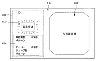
この場合のモニターによる前記合成映像信号に基づく画像表示例が図15に示されている。すなわち、図15に示すように、モニター6の画面6Aには、前記内視鏡バルーン情報画像6bを表示する領域の第1画面6Bと、内視鏡画像を表示する第2画面6Cとが例えば2画面に分割して表示されている。
An example of image display based on the composite video signal by the monitor in this case is shown in FIG. That is, as shown in FIG. 15, the
前記第1画面6Bは、上部に配された患者ID等の患者情報を表示したりする領域と、下部に配された前記内視鏡バルーン情報画像を表示する領域6bとを有している。
前記領域6bに表示される内視鏡バルーン情報画像としては、「内視鏡側バルーン」及び「オーバーチューブ側バルーン」の名称に相当する文字画像と、この文字画像に該当するバルーンの動作状態、例えば内視鏡側バルーン9が「収縮終了」、オーバーチューブ側バルーン11が「収縮終了」等の動作状態を示す文字画像とから構成されている。
The
The endoscope balloon information image displayed in the
なお、前記内視鏡バルーン情報画像は、文字画像に限定されることはなく、例えばアイコンなどの図柄を用いて表示するようにしても良い。 The endoscope balloon information image is not limited to a character image, and may be displayed using a pattern such as an icon, for example.
このように、本実施例の内視鏡バルーン制御装置7は、前記ビデオプロセッサ5による信号処理によって、モニター6の画面6A上に例えば第1、第2画面6B、6Cの2画面表示を行い、前記第1の画面6Bに前記内視鏡バルーン情報画像を表示すると同時に、前記第2画面6Cに前記内視鏡画像(内視鏡ライブ画像)を表示するようになっている。
Thus, the endoscope
次に、本実施例の内視鏡バルーン制御装置の作用について図15乃至図26を参照しながら説明する。
なお、前記内視鏡システム1の基本的な操作状態は前記第1実施例と同様である。したがって、本実施例の内視鏡バルーン制御装置7による表示制御動作について、前記第1実施例で説明した図5乃至図11に対応させて説明する。
Next, the operation of the endoscope balloon control device according to the present embodiment will be described with reference to FIGS.
The basic operation state of the
いま、術者が図1の内視鏡システム1を用いて消化管内内視鏡検査を行う際に、図3に示すリモートコントローラ8の電源ボタン22(あるいは図2に示す電源スイッチ17)を押下したとする。すると、前記内視鏡バルーン制御装置7の前記制御部35は、前記第1実施例と同様に図12に示すプログラムを起動して各バルーン9、11の駆動制御及びモニター6の表示制御を行う。
Now, when the surgeon performs the endoscopic examination of the digestive tract using the
いま、図5に示すように、術者はオーバーチューブ3内に内視鏡2を挿通させる。この場合、前記内視鏡2のバルーン9及び前記オーバーチューブ3のバルーン11は、それぞれ内部のエアを抜いてしぼませた状態とし、この状態で術者は被験者に対する内視鏡2の挿入を開始する。
このとき、前記内視鏡バルーン制御装置7は、図15に示すように、モニター6の画面6A上の第1画面6Bに、「内視鏡側バルーン」→「収縮終了」、「オーバーチューブ側バルーン」→「収縮終了」を示す内視鏡バルーン情報画像を表示すると同時に、第2画面6Cに内視鏡画像を表示する。なお、前記内視鏡バルーン制御装置7の電源投入時や初期化時においても、前記同様のモニタ画面6A(図15参照)が表示されるようになっている。また、本実施例では、前記第2画面6Cには常に内視鏡画像(内視鏡ライブ画像)が表示されるようになっているので、説明簡略化のため以降の説明は省略する。
Now, as shown in FIG. 5, the surgeon inserts the
At this time, as shown in FIG. 15, the endoscope
次に、術者は内視鏡2及びオーバーチューブ3の先端を、例えば十二指腸下行脚まで挿入したところで、図6に示すように、リモートコントローラ8のオーバーチューブ側の拡張/収縮ボタン20b(図3参照)を押下して前記第2ポンプ32bから前記オーバーチューブ3の先端に取り付けた本体固定用の前記バルーン11にエアを供給し、このバルーン11を膨らませて前記オーバーチューブ3を腸管40に固定する。
Next, when the operator inserts the distal ends of the
この場合、前記内視鏡バルーン制御装置7は、前記バルーン11のエア供給時、図16に示すように、モニター6の画面6A上の第1画面6Bに、「内視鏡側バルーン」→「収縮終了」、「オーバーチューブ側バルーン」→「拡張中」を示す内視鏡バルーン情報画像6bを表示する。そして、前記バルーン11のエア供給を終了してこのバルーン11が所望の状態に膨らんで腸管40に固定したときには、前記内視鏡バルーン制御装置7は、図17に示すように、モニター6の画面6A上の第1画面6Bに、「内視鏡側バルーン」→「収縮終了」、「オーバーチューブ側バルーン」→「拡張終了」を示す内視鏡バルーン情報画像を表示する。
In this case, the endoscope
次に、術者は、図7に示すように、前記オーバーチューブ3を腸管40に対して保持し、前記内視鏡2の前記挿入部2Bのみ深部に挿入させていく。
そして、術者は前記内視鏡2の前記挿入部2Bを所定距離挿入した状態で、図8に示すように、リモートコントローラ8の内視鏡側の拡張/収縮ボタン20a(図3参照)を押下して前記第1ポンプ32aから内視鏡2の先端に取り付けた本体固定用のバルーン9内にエアを供給し、このバルーン9を膨らませて腸管41に固定する。
Next, as shown in FIG. 7, the surgeon holds the
Then, with the
この場合、前記内視鏡バルーン制御装置7は、前記バルーン9のエア供給時、図18に示すように、モニター6の画面6A上の第1画面6Bに、「内視鏡側バルーン」→「拡張中」、「オーバーチューブ側バルーン」→「拡張終了」を示す内視鏡バルーン情報画像6bを表示する。そして、前記バルーン9のエア供給を終了して腸管41に固定したときには、前記内視鏡バルーン制御装置7は、図19に示すように、モニター6の画面6A上の第1画面6Bに、「内視鏡側バルーン」→「拡張終了」、「オーバーチューブ側バルーン」→「拡張終了」を示す内視鏡バルーン情報画像を表示する。
In this case, the endoscope
次に、術者は、前記リモートコントローラ8のオーバーチューブ側の拡張/収縮ボタン20b(図3参照)を押下して、前記管路切替部33により前記バルーン11内のエアを開放し、前記第2ポンプ32bから前記オーバーチューブ3の前記バルーン11内のエアを吸気して、前記バルーン11をしぼませる(図9参照)。
Next, the operator presses the expansion / contraction button 20b (see FIG. 3) on the overtube side of the
この場合、前記内視鏡バルーン制御装置7は、前記バルーン11のエア吸気時、図20に示すように、モニター6の画面6A上の第1画面6Bに、「内視鏡側バルーン」→「拡張終了」、「オーバーチューブ側バルーン」→「収縮中」を示す内視鏡バルーン情報画像6bを表示する。そして、前記バルーン11のエア吸気が終了したときには、前記内視鏡バルーン制御装置7は、図21に示すように、モニター6の画面6A上の第1画面6Bに、「内視鏡側バルーン」→「拡張終了」、「オーバーチューブ側バルーン」→「収縮終了」を示す内視鏡バルーン情報画像を表示する。
In this case, the endoscope
次いで、術者は、図9に示すように前記オーバーチューブ3を前記内視鏡2に沿わせて深部に挿入していき、前記内視鏡2の前記挿入部2Bの先端近くまで前記オーバーチューブ3の先端を挿入する。
Next, as shown in FIG. 9, the operator inserts the
そして、術者は、前記オーバーチューブ3の先端を前記挿入部2Bの先端近くまで挿入した状態で、図11に示すように、前記リモートコントローラ8のオーバーチューブ側の拡張/収縮ボタン20b(図3参照)を押下して前記第2ポンプ32bから前記オーバーチューブ3の前記バルーン11にエアを供給し、このバルーン11を膨らませて前記オーバーチューブ3を腸壁41に固定する。
Then, the surgeon inserts the distal end of the
この場合、前記内視鏡バルーン制御装置7は、前記バルーン11のエア供給時、図22に示すように、モニター6の画面6A上の第1画面6Bに、「内視鏡側バルーン」→「拡張終了」、「オーバーチューブ側バルーン」→「拡張中」を示す内視鏡バルーン情報画像6bを表示する。そして、前記バルーン11のエア供給を終了してこのバルーン11が所望の状態に膨らんで腸管41に固定したときには、前記内視鏡バルーン制御装置7は、図23に示すように、モニター6の画面6A上の第1画面6Bに、「内視鏡側バルーン」→「拡張終了」、「オーバーチューブ側バルーン」→「拡張終了」を示す内視鏡バルーン情報画像を表示する。
In this case, at the time of supplying air to the
その後、術者は、前記リモートコントローラ8の内視鏡側の拡張/収縮ボタン20a(図3参照)を押下して、前記管路切替部33により前記バルーン9内のエアを開放し、前記第1ポンプ32aから前記内視鏡2の前記バルーン9内のエアを吸気して、前記バルーン9をしぼませて、さらに前記挿入部2Bを深部に挿入させる。
Thereafter, the operator presses the expansion / contraction button 20a (see FIG. 3) on the endoscope side of the
この場合、前記内視鏡バルーン制御装置7は、前記バルーン9のエア吸気時、図24に示すように、モニター6の画面6A上の第1画面6Bに、「内視鏡側バルーン」→「収縮中」、「オーバーチューブ側バルーン」→「拡張終了」を示す内視鏡バルーン情報画像6bを表示する。そして、前記バルーン9のエア吸気が終了したときには、前記内視鏡バルーン制御装置7は、図25に示すように、モニター6の画面6A上の第1画面6Bに、「内視鏡側バルーン」→「収縮終了」、「オーバーチューブ側バルーン」→「拡張終了」を示す内視鏡バルーン情報画像6bを表示する。
In this case, when the
以上のような図5乃至図11の操作を繰り返すことにより、前記内視鏡2及び前記オーバーチューブ3の深部挿入を進めていくことになるが、本実施例の内視鏡バルーン制御装置7は、その操作状態に応じて前記各バルーン9、11の動作状態を、図15乃至図25に示すように内視鏡画像とともにモニター6の画面6A上に表示させるようになっている。
By repeating the operations of FIGS. 5 to 11 as described above, the deep insertion of the
また、本実施例では、上記内視鏡システム1の操作中に、術者によって前記リモートコントローラ8の緊急停止ボタン23(図3参照)が押下された場合には、前記内視鏡バルーン制御装置7は、図26に示すように、モニター6の画面6A上の第1画面6Bに、「内視鏡側バルーン」→「収縮中」、「オーバーチューブ側バルーン」→「収縮中」を示す内視鏡バルーン情報画像を表示し、第2画面6Cに内視鏡画像を表示すると同時に、新たに前記第1の画面6Bの領域6Xに「過送気緊急停止」といった警告文字を表示する。
In this embodiment, when the emergency stop button 23 (see FIG. 3) of the
なお、前記警告文字表示は、術者に確実に告知させるために点滅表示させたり、あるいは前記内視鏡バルーン情報画像とは異なる色で表示させても良い。 Note that the warning character display may be displayed in a blinking manner so that the operator can be surely notified, or may be displayed in a color different from the endoscope balloon information image.
したがって、本実施例によれば、モニター6の画面6A上に内視鏡画像ととともに各バルーン9、11の動作状態を示す内視鏡バルーン情報画像を表示することができるので、術者に対して各バルーン9、11の状態を効果的に認識させることが可能となる。その他の効果は、前記第1実施例と同様である。
Therefore, according to the present embodiment, the endoscope balloon information image indicating the operation state of each of the
本発明は、上述した第1及び第2実施例に限定されるものではなく、本発明の要旨を変えない範囲において、種々の変更、改変等が可能である。 The present invention is not limited to the first and second embodiments described above, and various changes and modifications can be made without departing from the scope of the present invention.
[付記]
(1)挿入部先端の外周部に固定用のバルーンを取り付けた内視鏡の前記バルーン及び、先端外周部に固定用のバルーンを取り付け、前記内視鏡を挿通させるオーバーチューブの前記バルーンにエアを供給するポンプを有し、前記ポンプを動作させてエアを供給制御する内視鏡用バルーン制御装置と、
前記内視鏡からの撮像信号を処理するビデオプロセッサと、
前記ビデオプロセッサにより処理された内視鏡画像を表示するモニターと、
前記内視鏡に照明光を供給する光源装置と、
前記内視鏡バルーン制御装置を操作するためのリモートコントローラと、を備え、
前記内視鏡バルーン制御装置は、前記各バルーンの状態を検出し、この検出した状態情報を出力するための状態情報出力手段を有することを特徴とする内視鏡システム。
[Appendix]
(1) Air in the balloon of the endoscope in which a fixing balloon is attached to the outer peripheral portion of the distal end of the insertion portion, and the balloon of the overtube in which the fixing balloon is attached to the outer peripheral portion of the distal end and the endoscope is inserted. An endoscopic balloon control device that controls the supply of air by operating the pump.
A video processor for processing an imaging signal from the endoscope;
A monitor for displaying an endoscopic image processed by the video processor;
A light source device for supplying illumination light to the endoscope;
A remote controller for operating the endoscope balloon control device,
The endoscope balloon control apparatus includes state information output means for detecting the state of each balloon and outputting the detected state information.
(2)挿入部先端の外周部に固定用のバルーンを取り付けた内視鏡の前記バルーン及び、先端外周部に固定用のバルーンを取り付け、前記内視鏡を挿通させるオーバーチューブの前記バルーンにエアを供給するポンプを有し、前記ポンプを動作させてエアを供給制御する内視鏡バルーン制御装置において、
前記各バルーンの状態を検出する状態検出手段と、この状態検出手段による検出結果に基づく表示を行うための状態情報を出力する状態情報出力手段とを設けたことを特徴とする内視鏡バルーン制御装置。
(2) Air in the balloon of the endoscope in which a fixing balloon is attached to the outer peripheral portion of the insertion portion and the balloon of the overtube in which the fixing balloon is attached to the outer periphery of the insertion portion and the endoscope is inserted. In an endoscope balloon control apparatus that controls the supply of air by operating the pump.
Endoscope balloon control characterized by comprising state detection means for detecting the state of each balloon and state information output means for outputting state information for performing display based on a detection result by the state detection means apparatus.
(3)前記状態情報出力手段は、前記内視鏡バルーン制御装置を操作するためのリモートコントローラに対し、このリモートコントローラに設けられた表示手段に前記状態情報に基づく表示を行うべく前記状態情報を出力することを特徴とする付記(2)に記載の内視鏡バルーン制御装置。 (3) The status information output means outputs the status information to a remote controller for operating the endoscope balloon control device so as to display based on the status information on a display means provided in the remote controller. The endoscope balloon control device according to appendix (2), wherein the endoscope balloon control device outputs the endoscope balloon.
(4)前記状態情報出力手段は、前記内視鏡からの撮像信号を処理して内視鏡画像を出力するビデオプロセッサに前記状態情報を出力し、
前記ビデオプロセッサは、前記状態情報に基づく画像と前記内視鏡による前記内視鏡画像とを合成して、前記内視鏡画像を表示するモニターに表示させることを特徴とする付記(2)に記載の内視鏡バルーン制御装置。
(4) The state information output means outputs the state information to a video processor that processes an imaging signal from the endoscope and outputs an endoscopic image,
The video processor is configured to synthesize an image based on the state information and the endoscopic image obtained by the endoscope and display the synthesized image on a monitor that displays the endoscopic image. The endoscope balloon control device described.
(5)前記状態情報は、前記各バルーンの動作中または非動作の動作状態を示すものであることを特徴とする付記(2)乃至付記(4)のいずれか1つに記載の内視鏡バルーン制御装置。 (5) The endoscope according to any one of supplementary notes (2) to (4), wherein the state information indicates an operational state of each balloon during operation or non-operation. Balloon control device.
(6)前記各バルーンの動作中を示す前記状態情報は、前記各バルーンの拡張状態または縮小状態を示すものである付記(5)に記載の内視鏡バルーン制御装置。 (6) The endoscope balloon control device according to (5), wherein the state information indicating that each balloon is in operation indicates an expanded state or a contracted state of each balloon.
(7)前記ビデオプロセッサは、前記内視鏡バルーン制御装置に接続されるリモートコントローラに設けられた前記緊急停止ボタンが押下された場合には前記状態情報に基づく画像に緊急停止情報に基づくを画像を表示させることとを特徴とする付記(4)に記載の内視鏡バルーン制御装置。 (7) When the emergency stop button provided on the remote controller connected to the endoscope balloon control device is pressed, the video processor displays an image based on the emergency stop information on the image based on the state information. The endoscope balloon control device according to appendix (4), characterized in that:
(8)前記状態情報出力手段は、前記リモートコントローラまたは前記ビデオプロセッサに有線、あるいは無線によって前記状態情報の通信が可能であることを特徴とする付記(3)又は付記(4)に記載の内視鏡バルーン制御装置。 (8) The state information output means is capable of communicating the state information to the remote controller or the video processor in a wired or wireless manner. Endoscopic balloon control device.
(9)前記内視鏡バルーン制御装置は、前記各バルーンへの送気または吸気流量を検出する流量検出手段を有し、この流量検出手段による検出結果に基づき前記ポンプを動作させて前記各バルーンへの送気または吸気流量を制御することを特徴とする付記(2)乃至付記(8)のいずれか1つに記載の内視鏡バルーン制御装置。 (9) The endoscope balloon control device has flow rate detection means for detecting an air supply or intake flow rate to each of the balloons, and operates each pump based on a detection result by the flow rate detection means. The endoscopic balloon control device according to any one of appendices (2) to (8), wherein the flow rate of air to or the flow rate of intake air is controlled.
本発明の内視鏡バルーン制御装置は、内視鏡のバルーンとオーバーチューブのバルーンの状態を術者に認識させることができるので、各バルーンを用いた深部の観察、処置等の症例や深部の様々な部位の観察、処置等の症例を行う場合には特に有効である。 Since the endoscope balloon control device of the present invention can make an operator recognize the state of the balloon of the endoscope and the balloon of the overtube, the observation of deep parts using each balloon, cases of treatment, etc. This is particularly effective when performing cases such as observation and treatment of various parts.
1…内視鏡システム、
2…内視鏡、
2A…操作部、
2B…挿入部、
2C…ユニバーサルコード、
3…オーバーチューブ、
4…光源装置、
5…ビデオプロセッサ、
6…モニター、
7…内視鏡バルーン制御装置、
8…リモートコントローラ、
9、11…バルーン、
10、12…エア供給チューブ、
12…内視鏡、
13…第1送気用チューブ、
14…第2送気用チューブ、
16…圧力表示器、
17…電源スイッチ、
23…緊急停止ボタン、
30…スイッチング電源部、
31a…第1プレーカ、
31b…第2プレーカ、
31c…第3プレーカ、
32a…第1ポンプ、
32b…第2ポンプ、
32c…第1流量調整バルブ、
32d…第2流量調整バルブ、
33…管路切替部、
33a…第1吸引バルブ、
33b…第1吐出バルブ、
33c…第2吸引バルブ、
33d…第2吐出バルブ、
34a…第1圧力センサ、
34b…第2圧力センサ、
35…制御部、
35a…状態検出出力部、
43…内視鏡画像生成部、
44…通信ユニット、
46…画像合成部。
代理人 弁理士 伊藤 進
1 ... endoscope system,
2. Endoscope,
2A ... operation unit,
2B ... insertion part,
2C ... Universal code,
3 ... Overtube,
4. Light source device,
5 ... Video processor,
6 ... Monitor,
7 ... Endoscopic balloon control device,
8 ... Remote controller,
9, 11 ... balloon,
10, 12 ... Air supply tube,
12 ... Endoscope,
13 ... First air supply tube,
14 ... Second air supply tube,
16 ... Pressure indicator,
17 ... Power switch,
23 ... Emergency stop button,
30: Switching power supply,
31a ... first player,
31b ... the second player,
31c ... Third player,
32a ... first pump,
32b ... second pump,
32c ... 1st flow regulating valve,
32d ... Second flow rate adjustment valve,
33 ... pipeline switching unit,
33a ... first suction valve,
33b ... 1st discharge valve,
33c ... second suction valve,
33d ... second discharge valve,
34a ... 1st pressure sensor,
34b ... second pressure sensor,
35 ... control unit,
35a ... state detection output unit,
43 ... Endoscopic image generator,
44. Communication unit,
46: Image composition unit.
Attorney Susumu Ito
Claims (3)
前記バルーンの拡張、収縮の状態を検出する状態検出手段と、この状態検出手段による検出結果に基づく表示を行うための状態情報を出力する状態情報出力手段と、
前記バルーンの動作、非動作の動作状況を検出する動作状況検出手段と、この動作状況検出手段による検出結果に基づく表示を行うための動作状況情報を出力する動作状況情報出力手段と、
を具備し、
前記状態情報出力手段および動作状況情報出力手段は、前記内視鏡バルーン制御装置を操作するためのリモートコントローラに対し、このリモートコントローラに設けられた表示手段に前記状態情報に基づく表示を行うべく前記状態情報および前記動作状況情報に基づく表示を行うべく、前記情報状態情報および前記動作状況情報を出力する
ことを特徴とする内視鏡バルーン制御装置。 An endoscope balloon control device that has a pump for supplying air to the balloon of an endoscope having a fixing balloon attached to the outer peripheral portion of the distal end of the insertion portion, and controls the supply of air by operating the pump. ,
Expanded before Kiba rune, a state detecting means for detecting a state of contraction, and the state information output means for outputting status information for performing display based on the detection result by the state detecting means,
An operation status detection means for detecting the operation status of the balloon and a non-operation status; an operation status information output means for outputting operation status information for performing display based on a detection result by the operation status detection means;
Comprising
The status information output means and the operation status information output means, with respect to a remote controller for operating the endoscope balloon control device, perform display based on the status information on a display means provided in the remote controller. The information status information and the operation status information are output for display based on the status information and the operation status information.
An endoscopic balloon control device characterized by the above .
前記バルーンの拡張、収縮の状態を検出する状態検出手段と、この状態検出手段による検出結果に基づく表示を行うための状態情報を出力する状態情報出力手段と、
前記バルーンの動作、非動作の動作状況を検出する動作状況検出手段と、この動作状況検出手段による検出結果に基づく表示を行うための動作状況情報を出力する動作状況情報出力手段と、
を具備し、
前記状態情報出力手段および動作状況情報出力手段は、前記内視鏡バルーン制御装置を操作するためのリモートコントローラに対し、このリモートコントローラに設けられた表示手段に前記状態情報に基づく表示を行うべく前記状態情報および前記動作状況情報に基づく表示を行うべく、前記情報状態情報および前記動作状況情報を出力する
ことを特徴とする内視鏡バルーン制御装置。 In an endoscope balloon control device that has a pump for supplying air to a balloon provided on the outer periphery of the distal end of an overtube through which an endoscope is inserted, and operates the pump to control supply of air.
State detection means for detecting states of expansion and contraction of the balloon, and state information output means for outputting state information for performing display based on the detection result by the state detection means;
An operation status detection means for detecting the operation status of the balloon and a non-operation status; an operation status information output means for outputting operation status information for performing display based on a detection result by the operation status detection means;
Comprising
The status information output means and the operation status information output means, with respect to a remote controller for operating the endoscope balloon control device, perform display based on the status information on a display means provided in the remote controller. The information status information and the operation status information are output for display based on the status information and the operation status information.
An endoscopic balloon control device characterized by the above .
前記各バルーンの拡張、収縮の状態を検出する状態検出手段と、この状態検出手段による検出結果に基づく表示を行うための状態情報を出力する状態情報出力手段と、
前記各バルーンの動作、非動作の動作状況を検出する動作状況検出手段と、この動作状況検出手段による検出結果に基づく表示を行うための動作状況情報を出力する動作状況情報出力手段と、
を具備し、
前記状態情報出力手段および動作状況情報出力手段は、前記内視鏡バルーン制御装置を操作するためのリモートコントローラに対し、このリモートコントローラに設けられた表示手段に前記状態情報に基づく表示を行うべく前記状態情報および前記動作状況情報に基づく表示を行うべく、前記情報状態情報および前記動作状況情報を出力する
ことを特徴とする内視鏡バルーン制御装置。 An endoscope balloon having a fixing balloon attached to the outer peripheral portion of the insertion portion distal end, and a pump for attaching air to the balloon of the overtube through which the endoscope is inserted by attaching the fixing balloon to the distal end outer peripheral portion. In an endoscope balloon control device that controls the supply of air by operating the pump,
State detection means for detecting the state of expansion and contraction of each balloon, state information output means for outputting state information for performing display based on the detection result by the state detection means,
Operation status detection means for detecting the operation status of each balloon and non-operation status, and operation status information output means for outputting operation status information for performing display based on the detection result by the operation status detection means,
Comprising
The status information output means and the operation status information output means, with respect to a remote controller for operating the endoscope balloon control device, perform display based on the status information on a display means provided in the remote controller. The information status information and the operation status information are output for display based on the status information and the operation status information.
An endoscopic balloon control device characterized by the above .
Priority Applications (8)
| Application Number | Priority Date | Filing Date | Title |
|---|---|---|---|
| JP2004115849A JP4409340B2 (en) | 2004-04-09 | 2004-04-09 | Endoscope balloon control device |
| DE602005025095T DE602005025095D1 (en) | 2004-04-09 | 2005-04-07 | ENDOSCOPE BALLOON CONTROL DEVICE |
| EP09003482A EP2110068B1 (en) | 2004-04-09 | 2005-04-07 | Endoscope balloon control device |
| CN2005800121984A CN1946330B (en) | 2004-04-09 | 2005-04-07 | Endoscope balloon control device |
| EP05728588A EP1731084B1 (en) | 2004-04-09 | 2005-04-07 | Endoscope balloon control device |
| PCT/JP2005/006874 WO2005096913A1 (en) | 2004-04-09 | 2005-04-07 | Endoscope balloon control device |
| CN2011101275192A CN102217925B (en) | 2004-04-09 | 2005-04-07 | Endoscope balloon control device |
| US11/545,678 US8096942B2 (en) | 2004-04-09 | 2006-10-10 | Endoscope balloon control device |
Applications Claiming Priority (1)
| Application Number | Priority Date | Filing Date | Title |
|---|---|---|---|
| JP2004115849A JP4409340B2 (en) | 2004-04-09 | 2004-04-09 | Endoscope balloon control device |
Publications (3)
| Publication Number | Publication Date |
|---|---|
| JP2005296258A JP2005296258A (en) | 2005-10-27 |
| JP2005296258A5 JP2005296258A5 (en) | 2007-04-19 |
| JP4409340B2 true JP4409340B2 (en) | 2010-02-03 |
Family
ID=35124777
Family Applications (1)
| Application Number | Title | Priority Date | Filing Date |
|---|---|---|---|
| JP2004115849A Expired - Lifetime JP4409340B2 (en) | 2004-04-09 | 2004-04-09 | Endoscope balloon control device |
Country Status (6)
| Country | Link |
|---|---|
| US (1) | US8096942B2 (en) |
| EP (2) | EP2110068B1 (en) |
| JP (1) | JP4409340B2 (en) |
| CN (2) | CN1946330B (en) |
| DE (1) | DE602005025095D1 (en) |
| WO (1) | WO2005096913A1 (en) |
Cited By (1)
| Publication number | Priority date | Publication date | Assignee | Title |
|---|---|---|---|---|
| EP3050490A1 (en) | 2015-01-29 | 2016-08-03 | Fujifilm Corporation | Remote controller for balloon controlling device and endoscope system |
Families Citing this family (35)
| Publication number | Priority date | Publication date | Assignee | Title |
|---|---|---|---|---|
| JP4409340B2 (en) * | 2004-04-09 | 2010-02-03 | オリンパス株式会社 | Endoscope balloon control device |
| JP5019757B2 (en) * | 2006-02-10 | 2012-09-05 | 富士フイルム株式会社 | Balloon control device |
| JP2008259701A (en) * | 2007-04-12 | 2008-10-30 | Olympus Corp | Apparatus inserted into living body |
| CN102573617B (en) | 2009-07-29 | 2014-09-10 | 梅奥医学教育和研究基金会 | Systems, devices and methods for assessment of body cavity pressures |
| EP2482744A4 (en) * | 2009-10-02 | 2017-01-04 | Cardiofocus, Inc. | Cardiac ablation system with inflatable member having multiple inflation settings |
| JP5647780B2 (en) * | 2009-10-20 | 2015-01-07 | Hoya株式会社 | Treatment overtube and treatment system |
| US11986150B2 (en) | 2009-12-15 | 2024-05-21 | Lumendi Ltd. | Method and apparatus for manipulating the side wall of a body lumen or body cavity so as to provide increased visualization of the same and/or increased access to the same, and/or for stabilizing instruments relative to the same |
| US11877722B2 (en) | 2009-12-15 | 2024-01-23 | Cornell University | Method and apparatus for manipulating the side wall of a body lumen or body cavity |
| WO2011084490A1 (en) | 2009-12-15 | 2011-07-14 | Cornell University | Method and apparatus for stabilizing, straightening, or expanding the wall of a lumen or cavity |
| US10149601B2 (en) | 2009-12-15 | 2018-12-11 | Lumendi Ltd. | Method and apparatus for manipulating the side wall of a body lumen or body cavity so as to provide increased visualization of the same and/or increased access to the same, and/or for stabilizing instruments relative to the same |
| US10485401B2 (en) | 2009-12-15 | 2019-11-26 | Lumendi Ltd. | Method and apparatus for manipulating the side wall of a body lumen or body cavity so as to provide increased visualization of the same and/or increased access to the same, and/or for stabilizing instruments relative to the same |
| US9986893B2 (en) | 2009-12-15 | 2018-06-05 | Cornell University | Method and apparatus for manipulating the side wall of a body lumen or body cavity so as to provide increased visualization of the same and/or increased access to the same, and/or for stabilizing instruments relative to the same |
| CN105147224B (en) | 2010-03-09 | 2018-11-02 | 智能医疗系统有限公司 | Sacculus endoscope and production and preparation method thereof |
| EP3998099A1 (en) | 2011-03-07 | 2022-05-18 | Smart Medical Systems Ltd. | Balloon-equipped endoscopic devices and methods thereof |
| JP2014188079A (en) * | 2013-03-26 | 2014-10-06 | Olympus Medical Systems Corp | Insertion device |
| JP6143516B2 (en) * | 2013-03-26 | 2017-06-07 | オリンパス株式会社 | Insertion device |
| CN114951189A (en) | 2013-05-21 | 2022-08-30 | 智能医疗系统有限公司 | Endoscope reprocessing system and method |
| CN103462583A (en) * | 2013-08-03 | 2013-12-25 | 徐怀 | Method for adjusting observation angle of endoscope |
| CN104640507B (en) * | 2013-08-22 | 2017-04-19 | 奥林巴斯株式会社 | Ultrasound endoscope and ultrasound balloon for endoscope |
| CA2971140A1 (en) | 2014-12-22 | 2016-06-30 | Smart Medical Systems Ltd. | Balloon endoscope reprocessing system and method |
| CN107427192A (en) | 2015-04-03 | 2017-12-01 | 智能医疗系统有限公司 | Endoscope electropneumatic adapter |
| US10765304B2 (en) * | 2015-09-28 | 2020-09-08 | Bio-Medical Engineering (HK) Limited | Endoscopic systems, devices, and methods for performing in vivo procedures |
| WO2017096350A1 (en) | 2015-12-05 | 2017-06-08 | The Regents Of The University Of Colorado, A Body Corporate | Novel endoscopic devices and methods using same |
| CN105640478A (en) * | 2015-12-17 | 2016-06-08 | 金吉安 | Double-sucker enteroscope |
| US11730928B2 (en) | 2018-01-16 | 2023-08-22 | Aspero Medical, Inc. | Split overtube assembly |
| WO2019143709A1 (en) | 2018-01-16 | 2019-07-25 | The Regents Of The University Of Colorado, A Body Corporate | Medical devices including textured inflatable balloons |
| US11577056B2 (en) | 2018-01-16 | 2023-02-14 | Aspero Medical, Inc. | Medical devices including textured inflatable balloons |
| CN112368048B (en) * | 2018-07-10 | 2022-08-30 | 奥林巴斯株式会社 | Phototherapy support device, phototherapy system, and phototherapy support method |
| JP7346017B2 (en) * | 2018-09-18 | 2023-09-19 | キヤノンメディカルシステムズ株式会社 | Magnetic resonance imaging device and static field magnet unit |
| US11229346B2 (en) * | 2018-11-15 | 2022-01-25 | Olympus Corporation | Medical method for a lumen |
| JP7320620B2 (en) * | 2019-12-26 | 2023-08-03 | 富士フイルム株式会社 | Endoscope and endoscope system |
| CN111759266B (en) * | 2020-07-17 | 2024-02-09 | 周国武 | Bronchoscope with safety capsule |
| CN111759259A (en) * | 2020-07-17 | 2020-10-13 | 周国武 | Plugging balloon catheter externally sleeved on bronchoscope |
| JP2023180472A (en) | 2022-06-09 | 2023-12-21 | 富士フイルム株式会社 | Endoscope apparatus |
| CN115154855A (en) * | 2022-07-12 | 2022-10-11 | 张琪 | Pressure expansion device |
Family Cites Families (23)
| Publication number | Priority date | Publication date | Assignee | Title |
|---|---|---|---|---|
| US3720199A (en) * | 1971-05-14 | 1973-03-13 | Avco Corp | Safety connector for balloon pump |
| US4040413A (en) * | 1974-07-18 | 1977-08-09 | Fuji Photo Optical Co. Ltd. | Endoscope |
| US4690131A (en) * | 1985-05-31 | 1987-09-01 | The United States Of America As Represented By The Department Of Health And Human Services | Medical apparatus |
| AU5998686A (en) * | 1985-06-05 | 1987-01-07 | Coopervision Inc. | Fluid flow control system and connecting fitting |
| US4676228A (en) * | 1985-10-25 | 1987-06-30 | Krasner Jerome L | Medical apparatus having inflatable cuffs and a middle expandable section |
| US5090259A (en) * | 1988-01-18 | 1992-02-25 | Olympus Optical Co., Ltd. | Pipe-inspecting apparatus having a self propelled unit |
| US5021046A (en) * | 1988-08-10 | 1991-06-04 | Utah Medical Products, Inc. | Medical pressure sensing and display system |
| US4934786A (en) * | 1989-08-07 | 1990-06-19 | Welch Allyn, Inc. | Walking borescope |
| JP3063784B2 (en) * | 1991-03-26 | 2000-07-12 | オリンパス光学工業株式会社 | Endoscope device |
| US5788688A (en) * | 1992-11-05 | 1998-08-04 | Bauer Laboratories, Inc. | Surgeon's command and control |
| JP3030348B2 (en) * | 1993-01-29 | 2000-04-10 | 富士写真光機株式会社 | Electronic endoscope |
| JPH08123595A (en) * | 1994-10-20 | 1996-05-17 | Olympus Optical Co Ltd | Keyboard device for medical use |
| US5749853A (en) * | 1995-03-17 | 1998-05-12 | Advanced Cardiovascular Systems, Inc. | Inflation control system with elapsed time measurement |
| US6270477B1 (en) * | 1996-05-20 | 2001-08-07 | Percusurge, Inc. | Catheter for emboli containment |
| US6007482A (en) * | 1996-12-20 | 1999-12-28 | Madni; Asad M. | Endoscope with stretchable flexible sheath covering |
| US20010020150A1 (en) * | 1998-02-06 | 2001-09-06 | Biagio Ravo | Inflatable intraluminal molding device |
| US6051016A (en) * | 1999-03-29 | 2000-04-18 | Instrumed, Inc. | System and method of controlling pressure in a surgical tourniquet |
| JP4517321B2 (en) * | 2000-06-05 | 2010-08-04 | 有限会社エスアールジェイ | Overtube |
| US6616597B2 (en) * | 2000-12-12 | 2003-09-09 | Datascope Investment Corp. | Intra-aortic balloon catheter having a dual sensor pressure sensing system |
| JP2002301019A (en) * | 2001-04-09 | 2002-10-15 | Hironori Yamamoto | Endoscope |
| JP3859491B2 (en) | 2001-11-15 | 2006-12-20 | オリンパス株式会社 | Endoscope sheath |
| JP3922217B2 (en) * | 2003-06-20 | 2007-05-30 | フジノン株式会社 | Endoscope device |
| JP4409340B2 (en) * | 2004-04-09 | 2010-02-03 | オリンパス株式会社 | Endoscope balloon control device |
-
2004
- 2004-04-09 JP JP2004115849A patent/JP4409340B2/en not_active Expired - Lifetime
-
2005
- 2005-04-07 CN CN2005800121984A patent/CN1946330B/en active Active
- 2005-04-07 CN CN2011101275192A patent/CN102217925B/en active Active
- 2005-04-07 DE DE602005025095T patent/DE602005025095D1/en active Active
- 2005-04-07 WO PCT/JP2005/006874 patent/WO2005096913A1/en not_active Application Discontinuation
- 2005-04-07 EP EP09003482A patent/EP2110068B1/en not_active Expired - Fee Related
- 2005-04-07 EP EP05728588A patent/EP1731084B1/en not_active Expired - Fee Related
-
2006
- 2006-10-10 US US11/545,678 patent/US8096942B2/en active Active
Cited By (2)
| Publication number | Priority date | Publication date | Assignee | Title |
|---|---|---|---|---|
| EP3050490A1 (en) | 2015-01-29 | 2016-08-03 | Fujifilm Corporation | Remote controller for balloon controlling device and endoscope system |
| US9968239B2 (en) | 2015-01-29 | 2018-05-15 | Fujifilm Corporation | Remote controller for balloon controlling device and endoscope system |
Also Published As
| Publication number | Publication date |
|---|---|
| EP2110068B1 (en) | 2011-08-03 |
| JP2005296258A (en) | 2005-10-27 |
| EP2110068A1 (en) | 2009-10-21 |
| WO2005096913A1 (en) | 2005-10-20 |
| CN102217925B (en) | 2012-11-14 |
| US8096942B2 (en) | 2012-01-17 |
| EP1731084A4 (en) | 2008-08-20 |
| CN1946330B (en) | 2011-07-13 |
| US20070055101A1 (en) | 2007-03-08 |
| CN1946330A (en) | 2007-04-11 |
| CN102217925A (en) | 2011-10-19 |
| EP1731084A1 (en) | 2006-12-13 |
| EP1731084B1 (en) | 2010-12-01 |
| DE602005025095D1 (en) | 2011-01-13 |
Similar Documents
| Publication | Publication Date | Title |
|---|---|---|
| JP4409340B2 (en) | Endoscope balloon control device | |
| KR100840050B1 (en) | Endoscope balloon control device | |
| EP1902661B1 (en) | Endoscope device | |
| JP4481692B2 (en) | Endoscope balloon control device | |
| JP2008212671A (en) | Therapeutic system | |
| JP2005279252A (en) | Endoscope system and method for operating endoscope | |
| JP2007209626A (en) | Balloon control device | |
| JP5242733B2 (en) | Endoscope balloon control device | |
| WO2005089625A1 (en) | Endoscope balloon control device and method of determining abnormality of endoscope balloon control device | |
| JP5165338B2 (en) | Endoscope system | |
| JP2005270335A (en) | Endoscope and endoscope apparatus | |
| JP4418285B2 (en) | Endoscope balloon control device | |
| US11141053B2 (en) | Endoscope apparatus and control apparatus | |
| JP4727224B2 (en) | Air supply device | |
| KR100848771B1 (en) | Endoscope balloon control device | |
| JP2005007030A (en) | Endoscope instrument | |
| JP2007111542A (en) | Endoscope apparatus | |
| JP5276259B2 (en) | Medical equipment | |
| JP2003010105A (en) | Endoscope system | |
| JP3031475B2 (en) | Endoscope device | |
| US20230397796A1 (en) | Endoscope device | |
| CN117241720A (en) | Control device, endoscope system, and control method | |
| WO2016009709A1 (en) | Endoscope system |
Legal Events
| Date | Code | Title | Description |
|---|---|---|---|
| A521 | Request for written amendment filed |
Free format text: JAPANESE INTERMEDIATE CODE: A523 Effective date: 20070301 |
|
| A621 | Written request for application examination |
Free format text: JAPANESE INTERMEDIATE CODE: A621 Effective date: 20070301 |
|
| A131 | Notification of reasons for refusal |
Free format text: JAPANESE INTERMEDIATE CODE: A131 Effective date: 20090714 |
|
| A521 | Request for written amendment filed |
Free format text: JAPANESE INTERMEDIATE CODE: A523 Effective date: 20090914 |
|
| TRDD | Decision of grant or rejection written | ||
| A01 | Written decision to grant a patent or to grant a registration (utility model) |
Free format text: JAPANESE INTERMEDIATE CODE: A01 Effective date: 20091020 |
|
| A01 | Written decision to grant a patent or to grant a registration (utility model) |
Free format text: JAPANESE INTERMEDIATE CODE: A01 |
|
| A61 | First payment of annual fees (during grant procedure) |
Free format text: JAPANESE INTERMEDIATE CODE: A61 Effective date: 20091111 |
|
| R151 | Written notification of patent or utility model registration |
Ref document number: 4409340 Country of ref document: JP Free format text: JAPANESE INTERMEDIATE CODE: R151 |
|
| FPAY | Renewal fee payment (event date is renewal date of database) |
Free format text: PAYMENT UNTIL: 20121120 Year of fee payment: 3 |
|
| FPAY | Renewal fee payment (event date is renewal date of database) |
Free format text: PAYMENT UNTIL: 20131120 Year of fee payment: 4 |
|
| S531 | Written request for registration of change of domicile |
Free format text: JAPANESE INTERMEDIATE CODE: R313531 |
|
| R350 | Written notification of registration of transfer |
Free format text: JAPANESE INTERMEDIATE CODE: R350 |
|
| R250 | Receipt of annual fees |
Free format text: JAPANESE INTERMEDIATE CODE: R250 |
|
| R250 | Receipt of annual fees |
Free format text: JAPANESE INTERMEDIATE CODE: R250 |
|
| R250 | Receipt of annual fees |
Free format text: JAPANESE INTERMEDIATE CODE: R250 |
|
| R250 | Receipt of annual fees |
Free format text: JAPANESE INTERMEDIATE CODE: R250 |
|
| R250 | Receipt of annual fees |
Free format text: JAPANESE INTERMEDIATE CODE: R250 |
|
| R250 | Receipt of annual fees |
Free format text: JAPANESE INTERMEDIATE CODE: R250 |