JP4383309B2 - Data communication apparatus and data communication system using the same - Google Patents
Data communication apparatus and data communication system using the same Download PDFInfo
- Publication number
- JP4383309B2 JP4383309B2 JP2004294871A JP2004294871A JP4383309B2 JP 4383309 B2 JP4383309 B2 JP 4383309B2 JP 2004294871 A JP2004294871 A JP 2004294871A JP 2004294871 A JP2004294871 A JP 2004294871A JP 4383309 B2 JP4383309 B2 JP 4383309B2
- Authority
- JP
- Japan
- Prior art keywords
- data
- video
- packet
- audio
- frame
- Prior art date
- Legal status (The legal status is an assumption and is not a legal conclusion. Google has not performed a legal analysis and makes no representation as to the accuracy of the status listed.)
- Active
Links
Images


Landscapes
- Data Exchanges In Wide-Area Networks (AREA)
Description
本発明は、LAN(Local Area Network)やインターネット等のネットワークを介して音声データや映像データの送受信を行うためのデータ通信装置及びそれを用いたデータ通信システムに関するものである。 The present invention relates to a data communication apparatus for transmitting and receiving audio data and video data via a network such as a LAN (Local Area Network) or the Internet, and a data communication system using the data communication apparatus.
近年、LANやインターネット等のネットワークを介して音声データや映像データを相手側の装置に送信する一方、相手側の装置から受信した映像データや音声データを再生することにより相互にリアルタイム通信を行うデータ通信装置が実用化されている。 In recent years, data that performs real-time communication with each other by playing back video data and audio data received from a partner device while transmitting voice data and video data to the partner device via a network such as a LAN or the Internet. Communication devices have been put into practical use.
この種のデータ通信装置では、音声データや映像データが複数のパケットに分割され、ネットワークを介して伝送されるが、帯域保証がなされていない経路で伝送される場合には、データが消失したりデータ伝送時間のずれ等が生じたりして音声と映像の再生タイミングが乱れることがある。 In this type of data communication apparatus, audio data and video data are divided into a plurality of packets and transmitted via a network. However, if the data is transmitted through a route with no bandwidth guarantee, the data may be lost. There is a case where the reproduction timing of audio and video is disturbed due to a difference in data transmission time or the like.
このような問題を解消するために、受信側で再生される音声と映像との同期ずれを解消するための技術が存在する。例えば、一定期間毎に受信されるデータ量の計測を行って得られたネットワークの帯域情報と受信データを格納するバッファ情報とに基づき、送信側装置がメディアストリームデータの符号化ビット量、サンプリング周波数、フレームレート等を動的に変更し、メディアストリームデータを送信することで、受信側装置におけるメディアストリームデータに含まれる音声や映像、または音声と映像の再生までの遅延時間を一定にし、音声や映像が途切れることなく連続して再生することを可能とした方法が知られている(特許文献1参照)。 In order to solve such a problem, there is a technique for eliminating a synchronization shift between audio and video reproduced on the receiving side. For example, based on the network bandwidth information obtained by measuring the amount of data received every fixed period and the buffer information for storing the received data, the transmission side apparatus can encode the bit amount of media stream data, the sampling frequency By dynamically changing the frame rate, etc. and transmitting the media stream data, the audio and video included in the media stream data in the receiving device or the delay time until the playback of the audio and video is made constant, and the audio and video There is known a method that enables video to be continuously reproduced without interruption (see Patent Document 1).
また、画像データ及び音声データからなる多重化データを通信網から受信して画像データと音声データとに分離する分離部と、画像データと音声データにタイムスタンプを付加するタイムスタンプ生成部と、付加されたタイムスタンプに基づき遅延差の吸収を行う遅延差吸収部とを備え、画像データ及び音声データの遅延差を吸収して通信網に送出することを可能としたデータ蓄積装置が知られている(特許文献2参照)。
しかし、上記従来の技術では以下のような問題が生じる。 However, the above-described conventional technique has the following problems.
上記特許文献1に記載の技術では、通信する装置のメモリサイズや処理能力に応じて音声や映像を連続再生することが可能となるが、あくまで装置のメモリサイズや処理能力に制限があることを前提とした技術であり、リアルタイム性が要求される通信において十分な通信帯域を確保できないような場合に適用することは困難であった。
With the technology described in
また、上記特許文献2に記載の技術では、音声及び画像の遅延差を吸収して通信網に送出することが可能となるが、音声と画像との遅延差をなくすための処理を行うにあたり、音声データ及び画像データからなる多重化データとして取扱うことが前提となるという不都合があった。
In the technique described in
本発明は、このような従来技術の問題点を解消するべく案出されたものであり、簡易な
構成によりネットワーク帯域の状態を的確に判断し、音声等の通信帯域を確保するとともに映像データの遅延を抑制することができるデータ通信装置及びそれを用いたデータ通信システムを提供することを目的とする。
The present invention has been devised to solve such problems of the prior art, and accurately determines the state of the network bandwidth with a simple configuration, ensures a communication bandwidth for voice and the like, and It shall be the object of the invention to provide a data communication system using the same and a data communication apparatus capable of suppressing the delay.
このような課題を解決するために、本発明によるデータ通信システムは、請求項1に示すとおり、パケット化された映像データ及び音声データを通信回線を介して相互に送受信する第1の通信装置及び第2の通信装置を有するデータ通信システムであって、前記第1の通信装置は、映像データ及び音声データを複数の映像パケット及び音声パケットとして前記第2の通信装置に対して順次送信するパケット送信部と、前記第2の通信装置から送られてくる映像データ及び音声データを映像パケット及び音声パケットとして順次受信するパケット受信部と、前記パケット受信部により前記第2の通信装置から受信した映像パケットのヘッダから、前記パケット送信部により送信した映像データの前記第2の通信装置における1フレーム毎の受信間隔の情報を取得するフレーム受信間隔取得部と、そのフレーム受信間隔取得部により取得された前記映像データの1フレーム毎の受信間隔がフレームレートの逆数であるフレーム間時間の2倍以上の場合に、相手側装置に送信する映像データのフレームレート及びビットレートの少なくとも一方を減少させるよう制御し、前記受信間隔が前記フレーム間時間以下となりその状態が一定時間以上継続した場合に、相手側装置に送信する映像データのフレームレート及びビットレートの少なくとも一方を増大させるよう制御する制御部とを備え、前記第2の通信装置は、前記第1の通信装置に対して映像データ及び音声データを複数の映像パケット及び音声パケットとして順次送信するパケット送信部と、前記第1の通信装置から映像パケット及び音声パケットとして送信される映像データ及び音声データを受信するパケット受信部と、前記パケット受信部により前記第1の通信装置から音声パケットを受信すると符号化音声データの復号化を優先して行い、音声パケットを受信していないときに映像パケットを受信してフレーム単位で符号化映像データが合成される時間間隔を計測することにより1フレーム毎の受信間隔を計測するタイマ部と、そのタイマ部により計測された映像データの1フレーム毎の受信間隔の情報を、前記パケット送信部により前記第1の通信装置に送信される映像パケットのヘッダの情報として設定するフレーム受信間隔設定部とを備えた構成とする。
To solve such problems, a data communication system according to the invention, as illustrated in
これによると、第2の通信装置における映像データの1フレーム毎の受信間隔の情報と、第2の通信装置に送信した映像データのフレームレートの情報とに基づいてネットワーク帯域の状態を的確に判断し、ネットワーク帯域の状態に応じて第2の通信装置に送信する映像のデータ量を適正に制御することで、音声データ用の通信帯域を確保できるとともに映像データの遅延を抑制することができる。
According to this, the information of the reception interval of each frame of the video data in the second communication device, accurately determine the state of the network bandwidth based on the information of the frame rate of the video data transmitted to the second communication device In addition, by appropriately controlling the amount of video data to be transmitted to the second communication device according to the state of the network band, it is possible to secure a communication band for audio data and to suppress delay of the video data .
また、第2の通信装置より受信する映像パケットによって、第2の通信装置から映像データの1フレーム毎の受信間隔の情報を容易に取得することができる。
Further, it is possible by the video packet received from the second communication device, easily obtain information on the reception interval of each frame of the video data from the second communication device.
また、第2の通信装置における映像データの1フレーム毎の受信間隔が、第2の通信装置に送信した映像データのフレーム間時間の2倍となったときに、ネットワークの輻輳発生の恐れがあると判断して第2の通信装置に送信する映像のデータ量を減少させることで、簡易かつ適切に音声データ用の通信帯域を確保できるとともに映像データの遅延を抑制することができる。
Further, the reception interval of each frame of the video data in the second communication apparatus, when the doubled between frames of the video data transmitted to the second communication device time, there is a risk of network congestion By reducing the amount of video data to be transmitted to the second communication device , it is possible to easily and appropriately secure a communication band for audio data and to suppress delay of video data.
また、第2の通信装置における映像データの1フレーム毎の受信間隔が、第2の通信装置に送信した映像データのフレーム間時間以下となる状態が一定時間以上継続したときに、ネットワーク帯域に余裕があると判断して第2の通信装置に送信する映像のデータ量を増加させることで、より高画質な映像データの通信が可能となる。
In addition , when the state in which the reception interval for each frame of video data in the second communication device is equal to or less than the time between frames of the video data transmitted to the second communication device continues for a certain time or more, there is a margin in the network bandwidth. By determining that there is an image and increasing the amount of video data to be transmitted to the second communication device , it is possible to communicate video data with higher image quality.
このように本発明によれば、ネットワークを介して音声データや映像データの送受信を行うに際し、簡易な構成によりネットワーク帯域の状態を的確に判断し、音声等の通信帯域を確保するとともに映像の遅延を低減することができる。 As described above, according to the present invention, when audio data or video data is transmitted / received via a network, the state of the network band is accurately determined with a simple configuration, and a communication band for audio and the like is ensured and a video delay is ensured. Ru can be reduced.
以下、本発明の実施の形態を、図面を参照しながら説明する。 Hereinafter, embodiments of the present invention will be described with reference to the drawings.
(第1の実施の形態)
図1は、本発明の第1の実施の形態に係るデータ通信装置の概略構成を示すブロック図である。このデータ通信装置1は、LANやインターネット等のネットワークを介して音声データや映像データを相手側装置に送信する一方、受信した音声データや映像データをリアルタイムで再生することが可能であり、オーディオエンコーダ2、ビデオエンコーダ3、パケット送信部4、パケット受信部5、受信パケットフレーム合成部6、オーディオデコーダ7、ビデオデコーダ8、フレーム受信間隔計測タイマ9、フレーム受信間隔設定部10、フレーム受信間隔取得部11、積分カウンタ12、ネットワークインタフェース13、マイク14、ディスプレイ15、カメラ16、スピーカ17、及び制御部18を備える。ここで、本発明に好適な伝送プロトコルとして、RTP(Real-time Transport Protocol)を用いることができる。以下、本実施の形態においては、音声パケット及び映像パケットは、RTPパケットとして取扱うものとする。
(First embodiment)
FIG. 1 is a block diagram showing a schematic configuration of a data communication apparatus according to the first embodiment of the present invention. The
オーディオエンコーダ2は、マイク14からの音声データの圧縮や暗号化等の処理を行い、符号化音声データを生成する。また、ビデオエンコーダ3は、カメラ16からのビデオフレーム(映像データ)の圧縮や暗号化等の処理を行い、フレーム単位で符号化映像データを生成する。
The
パケット送信部4は、オーディオエンコーダ2及びビデオエンコーダ3によってそれぞれ生成された符号化音声データ及び符号化映像データをパケット化し、生成した音声パケット及び映像パケットをネットワークを介して相手側装置に対して順次送信する。
The packet transmission unit 4 packetizes the encoded audio data and the encoded video data generated by the
パケット受信部5は、相手側装置から送られてくる音声パケット及び映像パケットを受信し、それらのパケットから符号化音声データ及び符号化映像データをそれぞれ取り出す。また、受信パケットフレーム合成部6は、パケット受信部5により映像パケットから取り出された複数の符号化映像データをフレーム単位で合成する。
The
オーディオデコーダ7は、相手側装置より受信した符号化音声データを復号化し、スピーカ15から出力するための音声データを生成する。また、ビデオデコーダ8は、相手側装置より受信した符号化映像データを復号化し、ディスプレイ15に表示するための映像データを生成する。
The audio decoder 7 decodes the encoded audio data received from the counterpart device, and generates audio data to be output from the
フレーム受信間隔計測タイマ9は、パケット受信部5により受信される映像パケットについて、1フレーム毎の受信間隔を計測する。本実施の形態では、1フレーム毎の受信間隔として、受信パケットフレーム合成部6によりフレーム単位で符号化映像データが合成される時間間隔を計測する。
The frame reception
フレーム受信間隔設定部10は、相手側装置にネットワーク帯域の状態を認識させるべく、タイマ9により計測された映像データの1フレーム毎の受信間隔の情報を、パケット送信部4により送信される映像パケットのヘッダに付加する。
The frame reception
フレーム受信間隔取得部11は、相手側装置から受信した映像パケットのヘッダに相手側装置における1フレーム毎の受信間隔の情報が含まれている場合に、その1フレーム毎の受信間隔の情報を取得する。
The frame reception
ネットワークインタフェース13は、データ通信装置1をLANやインターネット等のネットワークに接続するためのインタフェースである。
The
制御部18は、上記各部を統括的に制御する。また、制御部18は、相手側装置との通信において、フレーム受信間隔取得部11により取得された相手側装置における映像データの1フレーム毎の受信間隔の情報と、相手側装置に送信する映像データのフレームレートの情報とに基づき、相手側装置に送信する映像データのデータ量(例えば、フレームレート及びビットレートの少なくとも一方)を制御する。
The
図2は、図1に示したデータ通信装置を用いたデータ通信システムにおける映像データの流れの一例を示す模式図である。このデータ通信システム20は、図1に示したデータ通信装置1と同一の2つの装置(第1の通信装置1a及び第2の通信装置1b)がネットワーク21を介して相互に通信可能なように接続された構成を有する。説明の便宜上、ここでは主として第1の通信装置1aを送信側の装置とし、第2の通信装置1bを受信側の装置として音声データ及び映像データの流れを示す。また、これらの通信装置1a、1bについては必要な構成要素のみを示してある。
FIG. 2 is a schematic diagram showing an example of the flow of video data in a data communication system using the data communication apparatus shown in FIG. The
第1の通信装置1aのカメラ16aで撮影された映像は、複数のビデオフレームで構成される映像データとしてビデオエンコーダ3aに送られ、そこで、フレーム単位で符号化され複数のビデオパケットを含む符号化映像データが生成される。その符号化映像データは、パケット送信部4aに送られて複数の映像パケット(RTPパケット)に分割され、ネットワーク21を介して第2の通信装置1bに対して順次送信される。なお、ここでの説明は省略するが、RTPパケットは、さらにUDP(User Datagram Protocol)パケット化やIP(Internet Protocol)パケット化等の処理を行ってからネットワーク21に送出されるのが一般的である。
The video shot by the
第1の通信装置1aから送られたそれらの映像パケットは、第2の通信装置1bのパケット受信部5bで受信され、そこで、そのパケット受信部5bにより映像パケットから符号化映像データが取り出され、それらの符号化映像データは受信パケットフレーム合成部6bによりフレーム単位で合成される。さらに、そのフレーム単位の符号化映像データは、ビデオデコーダ8bにより復号化され、そこで生成されたビデオフレームに基づきディスプレイ14bに映像が表示される。
Those video packets sent from the
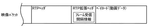
その一方で、第2の通信装置1bにおいて、受信パケットフレーム合成部6bによってフレーム単位で符号化映像データが合成される時間間隔が、フレーム受信間隔計測タイマ9bにより計測され、その測定結果は、フレーム受信間隔情報としてフレーム受信間隔設定部10bに送られる。その受信間隔情報は、フレーム受信間隔設定部10bにより、図3に示すように、第2の通信装置1bから送信される映像パケットの拡張ヘッダに付加される。そこで、フレーム受信間隔情報が付加された映像パケットは、パケット送信部4bによりネットワーク21を介して第1の通信装置1aに対して送信される。
On the other hand, in the
第2の通信装置1bから送られた映像パケットは、第1の通信装置1aのパケット受信部5aで受信され、そこで、その映像パケットの拡張ヘッダに含まれる第2の通信装置1bにおけるフレーム受信間隔情報がフレーム受信間隔取得部11aにより取得される。
The video packet sent from the
第1の通信装置1aの制御部18aは、フレーム受信間隔取得部11aから得られたフレーム受信間隔情報と、ビデオエンコーダ3aから得られたフレームレートの情報とに基づき、第2の通信装置に送信する映像データのデータ量の変更指令をビデオエンコーダ3aに対して送る。
The
より詳細には、制御部18aは、第2の通信装置1bにおける映像データの1フレーム毎の受信間隔TR(sec)が、ビデオエンコーダ3aから得られたフレームレート(frame/sec)の逆数であるフレーム間時間TF(sec)よりも十分大きな値となった場合に、相手側装置に送信する映像データのフレームレート及びビットレートの少なくとも一方を減少させるようにビデオエンコーダ3aを制御する。ここで、「十分大きな値」としては、映像データの1フレーム毎の受信間隔TRが、フレーム間時間TFの2倍以上となることが好ましく、例えば、TFが33msec(フレームレート30frame/sec)のときに、TRが66msec以上となった場合が挙げられる。その一方で、制御部18aは、第2の通信装置1bにおける映像データの1フレーム毎の受信間隔TR(sec)が、ビデオエンコーダ3aから得られたフレームレートの逆数であるフレーム間時間TF(sec)以下の値となり、その状態が一定時間以上継続した場合に、相手側装置に送信する映像データのフレームレート及びビットレートの少なくとも一方を増大させるようにビデオエンコーダ3aを制御する。
More specifically, the
図4は、図1に示したデータ通信装置を用いたデータ通信システムにおける音声データ及び映像データの通信動作を示すフロー図である。ここで、(a)及び(b)は、図1のデータ通信装置1と同一の2つの装置(データ通信装置A、データ通信装置B)が、データ通信システムにおいてネットワークを介して相互に通信する動作を示している。なお、ここでは説明の便宜上、データ通信装置Aが、通信相手であるデータ通信装置Bから映像データの1フレーム毎の受信間隔の情報を取得し、データ通信装置Bに対して送信する映像データのデータ量を変更する動作を主として示す。
FIG. 4 is a flowchart showing a communication operation of audio data and video data in a data communication system using the data communication apparatus shown in FIG. Here, in (a) and (b), two devices (data communication device A and data communication device B) identical to the
まず、データ通信装置Aでは、映像及び音声の送信を行うために、ビデオエンコーダ3及びオーディオエンコーダ2がそれぞれ起動され、映像データ及び音声データの符号化が行われる(ST1、ST2)。続いて、データ通信装置Bに送信する映像データのデータ量を変更する指標として用いられる積分カウンタ12の値が初期化される(ST3)。一方、データ通信装置Bでは、データ通信装置Aから受信する符号化データの復号化を行う準備として、ビデオデコーダ8及びオーディオデコーダ7がそれぞれ起動される(ST31、ST32)。
First, in the data communication apparatus A, in order to transmit video and audio, the
次に、データ通信装置Aでは、ビデオエンコーダ3及びオーディオエンコーダ2において符号化された映像及び音声の符号化データが、パケット送信部4によりパケット化され、それぞれ映像パケット及び音声パケットとしてデータ通信装置Bに対して順次送信される(ST4、ST5)。
Next, in the data communication apparatus A, the encoded video and audio data encoded by the
一方、データ通信装置Bでは、音声パケットを受信したか否かが判定され(ST33)、音声パケットを受信すると、オーディオデコーダ7により符号化音声データが復号化される(ST34)。ステップST34において、音声パケットを受信していないと判定された場合には、さらに、映像パケットを受信したか否かが判定され(ST35)、映像パケットを受信すると、受信パケットのフレーム化が実行される(ST36)。一方、映像パケットを受信していない場合には、再びステップST33に戻って音声パケットを受信したか否かが判定される。そこで、データ通信装置Bでは、受信した映像パケットのフレーム化が完了したか否かが判定され(ST37)、フレーム化が完了していない場合には、再びステップST33に戻ってフレーム化が完了するまで映像パケットの受信を繰り返し実行する。 On the other hand, in data communication apparatus B, it is determined whether or not a voice packet has been received (ST33). When the voice packet is received, encoded audio data is decoded by audio decoder 7 (ST34). If it is determined in step ST34 that no audio packet has been received, it is further determined whether a video packet has been received (ST35). When a video packet is received, the received packet is framed. (ST36). On the other hand, if a video packet has not been received, the process returns to step ST33 again to determine whether an audio packet has been received. Therefore, the data communication apparatus B determines whether or not the received video packet has been framed (ST37). If the frame has not been completed, the process returns to step ST33 to complete the frame. Until the video packet is received repeatedly.
ステップST37において、映像パケットのフレーム化が完了すると、フレームの受信間隔を計測中であるか否かが判定され(ST38)、計測が開始されていない場合には、タイマ9にフレーム受信間隔の計測を開始させる(ST39)。一方、ステップST38において、既にフレームの受信間隔の計測が開始されている場合には、その計測を停止し(ST40)、そこでの計測結果が、次にデータ通信装置Aに対して送信される映像パケットのヘッダの情報としてフレーム受信間隔設定部10により設定される(ST41)。そこで、次のフレームの受信間隔を計測するために、タイマ9が再び計測を開始する(ST42)。次に、フレーム化された符号化映像データが復号化され(ST43)、さらに、通信が終了したか否かが判定され(ST44)、通信が終了していない場合には、再びステップST33に戻って上記と同様の動作を繰り返し実行する。最終的に、ステップ44において、通信が終了していると判断されるとデータ通信装置Bの動作は完了する。
In step ST37, when the framing of the video packet is completed, it is determined whether or not the frame reception interval is being measured (ST38). If the measurement has not started, the
次に、データ通信装置Aでは、データ通信装置Bから受信した映像パケットのヘッダにフレームの受信間隔の情報(1フレーム毎の受信間隔TR(sec))が付加されているか否かが判定され(ST6)、フレームの受信間隔の情報が付加されている場合には、データ通信装置Bに送信される映像データのフレーム間時間TF(sec)よりも十分大きいか否かが判定される(ST7)。そこで、TRがTFよりも十分大きいと判定された場合には、制御部18は、ビデオエンコーダ3において映像の符号化のデータ量を低減するように制御する(ST8)。一方、ステップST7において、TRがTFよりも十分大きいとはいえない場合には、さらに、TRがTF以下であるか否かが判定される(ST9)。そこで、TRがTF以下であると判定された場合には、積分カウンタ12の値がカウントアップされ(ST10)、TRがTF以下でない場合には、積分カウンタ12の値がゼロに戻される(ST11)。次に、積分カウンタ12の値が予め設定した閾値N以上であるか否かが判定され(ST12)、積分カウンタ12の値が閾値N以上となった場合には、ネットワーク帯域に十分な余裕があると判断して、制御部18は、ビデオエンコーダ3において映像の符号化のデータ量を増大させるように制御する(ST13)。一方、積分カウンタ12の値が閾値N未満である場合には、続いて、通信が終了したか否かが判定され(ST14)、通信が終了していない場合には、再びステップST4に戻って上記と同様の動作を繰り返し実行する。同様に、ステップST6において、映像パケットのヘッダにフレームの受信間隔の情報が付加されていない場合にも、通信が終了したか否かが判定され(ST14)、通信が終了していない場合には、再びステップST4に戻って上記と同様の動作を繰り返し実行する。最終的に、ステップ14において、通信が終了していると判断されるとデータ通信装置Aの動作は完了する。
Next, in the data communication device A, it is determined whether or not frame reception interval information (reception interval T R (sec) for each frame) is added to the header of the video packet received from the data communication device B. (ST6) When the information of the frame reception interval is added, it is determined whether or not it is sufficiently larger than the inter-frame time T F (sec) of the video data transmitted to the data communication apparatus B ( ST7). Therefore, if it is determined that T R is sufficiently larger than T F , the
(第2の実施の形態)
図5は、本発明の第2の実施の形態に係るデータ通信装置の概略構成を示すブロック図である。このデータ通信装置101は、図1に示したデータ通信装置1と概ね同様の構成を有し、オーディオエンコーダ2、ビデオエンコーダ3、パケット送信部4、パケット受信部5、受信パケットフレーム合成部6、オーディオデコーダ7、ビデオデコーダ8、同期時刻情報設定部102、同期時刻情報設定用タイマ103、同期時刻情報検出部104、ネットワークインタフェース13、マイク14、ディスプレイ15、カメラ16、スピーカ17、及び制御部18を備える。ここで、図1に示したデータ通信装置1と同様の構成要素については同一の符号が付されており、これらの構成要素については、以下で特に言及しない限り同様の機能を果たすものとする。
(Second Embodiment)
FIG. 5 is a block diagram showing a schematic configuration of the data communication apparatus according to the second embodiment of the present invention. This
同期時刻情報設定部102は、パケット送信部4により音声パケット及び映像パケットが相手側装置に対して送信される際に、音声パケットまたは映像パケットの一方のパケットにおけるデータ内タイムスタンプ(データ内同期時刻情報)を、音声データ及び映像データ間で同期をとるためのデータ間タイムスタンプ(データ間同期時刻情報)として他方のパケットの拡張ヘッダに記録する。さらに、同期時刻情報設定部102は、拡張ヘッダのデータ間タイムスタンプが有効であるか否かを識別するための有効フラグ(識別子)をパケットの拡張ヘッダに記録する。ここで、データ内タイムスタンプとしては、通常のRTPパケットのヘッダに付加されるタイムスタンプを用いることができる。
When the packet transmission unit 4 transmits the audio packet and the video packet to the counterpart device, the synchronization time
同期時刻情報設定用タイマ103は、同期時刻情報設定部102が音声パケット及び映像パケットの一方のパケットにおけるデータ内タイムスタンプを、他方のパケットの拡張ヘッダにデータ間タイムスタンプとして記録するタイミングを計測する。
The synchronization time
同期時刻情報検出部104は、相手側装置からパケット受信部5が受信した音声パケットまたは映像パケットに付加されたデータ間タイムスタンプを検出する。このとき、同期時刻情報検出部104は、パケットに付された有効フラグによってデータ間タイムスタンプの有効または無効を判断することができる。
The synchronization time
制御部18は、同期時刻情報検出部104により音声パケットまたは映像パケットに付された有効なデータ間タイムスタンプが検出されたときに、オーディオデコーダ7またはビデオデコーダ8により音声または映像の一方のパケットにより再構成されたデータの復号化を実行させる一方、他方のパケットにより再構成されたデータの復号化については、他方のパケットのヘッダに記録されたデータ内タイムスタンプがデータ間タイムスタンプと同一またはより遅い時刻を示している場合にのみ実行させる。
When the valid time stamp between data attached to the audio packet or the video packet is detected by the synchronization time
一般に、音声データに比べて映像データのデータ量が大きくなるため、ネットワーク等の通信回線での伝送遅延差等により、相手側装置における映像データと音声データの受信タイミングは、音声パケットの受信タイミングに対して映像パケットの受信タイミングの方が遅れる傾向にある。そこで、以下では、本発明によるデータ間タイムスタンプが音声パケットに付されるケースを典型例として説明する。なお、データ間タイムスタンプが映像パケットに付される場合については、音声のケースと同様にして実行可能である。 In general, since the amount of video data is larger than that of audio data, the reception timing of the video data and audio data at the counterpart device is the same as the reception timing of the audio packet due to the transmission delay difference in the communication line such as a network. On the other hand, the reception timing of video packets tends to be delayed. Therefore, in the following, a case where an inter-data time stamp according to the present invention is attached to a voice packet will be described as a typical example. It should be noted that the case where the inter-data time stamp is attached to the video packet can be executed in the same manner as in the audio case.
図6は、図5に示したデータ通信装置を用いたデータ通信システムにおける音声データ及び映像データの流れの一例を示す模式図である。このデータ通信システム120は、図5に示したデータ通信装置1と同一の2つの装置(第3の通信装置101a及び第4の通信装置101b)がネットワーク21を介して相互に通信可能なように接続された構成を有する。説明の便宜上、ここでは第3の通信装置101aを送信側の装置とし、第4の通信装置101bを受信側の装置として音声データ及び映像データの流れを示す。また、これらの通信装置101a、101bについては必要な構成要素のみを示してある。
FIG. 6 is a schematic diagram showing an example of the flow of audio data and video data in a data communication system using the data communication apparatus shown in FIG. The data communication system 120 is configured so that two devices (
第3の通信装置101aのマイク14aに入力された音声は、音声データとしてオーディオエンコーダ2aに送られて符号化され、その符号化された音声データがパケット送信部4aに送られる。一方、第3の通信装置101aのカメラ16aで撮影された映像は、映像データとしてビデオエンコーダ3aに送られて符号化され、その符号化された映像データがパケット送信部4aに送られる。ここで、タイマ103aは、同期時刻情報設定部102aに対し、所定の周期(例えば、1秒周期)で映像パケットのデータ内タイムスタンプTSRを音声パケットにデータ間タイムスタンプTSLとして記録するタイミングを示す信号を送る。
The voice input to the
これにより、同期時刻情報設定部102aは、パケット送信部4aにより映像パケットが第4の通信装置101bに対して送信される際に、図7に示すように、映像パケットのヘッダに記録されたデータ内タイムスタンプTSRを音声パケットの拡張ヘッダにデータ間タイムスタンプTSLとして記録する。さらに、同期時刻情報設定部102aは、拡張ヘッダのデータ間タイムスタンプTSLが有効であることを示す有効フラグを拡張ヘッダに記録する。
As a result, when the
第3の通信装置101aのパケット送信部4aにより送信された音声パケット及び映像パケットは、第4の通信装置101bのパケット受信部5bにより受信される。そこで、同期時刻情報検出部104bは、音声パケットの拡張ヘッダに記録された有効フラグを確認し、データ間タイムスタンプTSLが有効である場合には、拡張ヘッダに記録されたデータ間タイムスタンプTSLを検出して順次保存する。さらに、制御部18bは、保存された最新のデータ間タイムスタンプTSLとパケット受信部5bで受信された映像パケットのデータ内タイムスタンプTSRとを比較し、TSRがTSLと同一または遅い時刻を示している場合にのみ、ビデオエンコーダ8bにパケット受信部5bから送られる符号化映像データを復号化させる。従って、パケット受信部5bからの符号化音声データがオーディオデコーダ7bで復号化されてスピーカ17bから音声が出力される一方、符号化映像データは、その音声の出力に同期する映像のみがビデオエンコーダ8bにおいて復号化され、ディスプレイ15bに表示されることになる。
The audio packet and the video packet transmitted by the
図8は、図5に示したデータ通信装置においてデータ間タイムスタンプを設定するタイミングを示すタイムチャートである。ここでは、パケット送信部4において音声パケット(音声1〜音声6)及び映像パケット(映像1〜映像4)が順次生成(送信)される様子が模式的に示されており、タイマ103により同期時刻情報検出部104に対して同期時刻情報を設定するタイミングが示されると(図中、破線参照)、同期時刻情報検出部104は、次に生成される映像パケット(映像3)のデータ内タイムスタンプTSL(映像タイムスタンプ情報)を、次に生成される音声パケット(音声4)の拡張ヘッダに記録する。同時に、拡張ヘッダのデータ間タイムスタンプTSLが有効であることを示す有効フラグを拡張ヘッダに記録する。
FIG. 8 is a time chart showing the timing for setting an inter-data time stamp in the data communication apparatus shown in FIG. Here, the state in which the packet transmission unit 4 sequentially generates (transmits) audio packets (audio 1 to audio 6) and video packets (
図9は、図5に示したデータ通信装置を用いたデータ通信システムにおける音声データ及び映像データの通信動作を示すフロー図である。ここで、(a)及び(b)は、図5のデータ通信装置1と同一の2つの装置(データ通信装置C、データ通信装置D)が、データ通信システムにおいてネットワークを介して相互に通信する動作を示している。なお、ここでは説明の便宜上、データ通信装置Cが、音声データ及び映像データ間で同期をとるためのデータ間タイムスタンプを記録した音声パケットをデータ通信装置Dに対して送信し、そのデータ間タイムスタンプに基づきデータ通信装置Dが、映像パケットを選択的に復号化して音声と映像との同期ずれを解消する動作を主として示す。
FIG. 9 is a flowchart showing a communication operation of audio data and video data in a data communication system using the data communication apparatus shown in FIG. Here, in (a) and (b), two devices (data communication device C and data communication device D) identical to the
まず、データ通信装置Cでは、映像及び音声の送信を行うために、ビデオエンコーダ3及びオーディオエンコーダ2がそれぞれ起動され、映像データ及び音声データの符号化が行われる(ST101、ST102)。一方、データ通信装置Dでは、データ通信装置Cから受信する符号化データの復号化を行う準備として、ビデオデコーダ8及びオーディオデコーダ7がそれぞれ起動される(ST131、ST132)。
First, in the data communication apparatus C, in order to transmit video and audio, the
次に、データ通信装置Cでは、同期時刻情報の設定タイミングを指示するために、予め所定の周期が設定されたタイマ103が起動される(ST103)。そこで、タイマ103がタイムアウトしたか否かが判定され(ST104)、タイムアウトになると、同期時刻情報設定部102は、パケット送信部4により次に送信される映像パケットのヘッダのデータ内タイムスタンプTSRを、次に送信される音声パケットの拡張ヘッダにデータ間タイムスタンプTSLとして記録し、さらに、データ間タイムスタンプTSLが有効であることを示す有効フラグを付加する(ST105)。一方、ステップST104において、タイムアウトになっていない場合には、次に送信される音声パケットの拡張ヘッダには、データ間タイムスタンプTSLは記録されることはなく、データ間タイムスタンプTSLが無効であることを示す有効フラグが付加される。その後、それらの映像パケット及び音声パケットは、パケット送信部4によりデータ通信装置Dに対して順次送信される(ST106、ST107)。上記ステップST104〜ST107は、最終的に通信が終了したと判定されるまで(ST108:Yes)、繰り返し実行される。
Next, in the data communication apparatus C, in order to instruct the setting timing of the synchronization time information, the
一方、データ通信装置Dでは、データ通信装置Cのパケット送信部4により送信された音声パケットを受信したか否かが判定され(ST133)、音声パケットを受信すると、さらに、その音声パケットの拡張ヘッダにおける有効フラグを確認することにより、音声パケット上に有効なデータ間タイムスタンプTSLが存在するか否かが判定される(ST134)。そこで、データ間タイムスタンプが存在する場合には、そのデータ間タイムスタンプ情報が保存される(ST135)。ここで保存されるデータ間タイムスタンプ情報は、有効なデータ間タイムスタンプTSLを含む音声パケットを受信するたびに更新される。ステップST133において受信された音声パケットは、符号化音声データとしてオーディオデコーダ7に送られ復号化される(ST136)。一方、ステップST133において音声パケットを受信していない場合には、映像パケットの受信ステップに進む。 On the other hand, in the data communication device D, it is determined whether or not the voice packet transmitted by the packet transmission unit 4 of the data communication device C is received (ST133). When the voice packet is received, the extension header of the voice packet is further received. in by confirming the valid flag, whether valid data between timestamps TS L on voice packet exists is determined (ST134). Therefore, if an inter-data time stamp exists, the inter-data time stamp information is stored (ST135). Where the data between the time stamp information stored is updated each time it receives a voice packet including a timestamp TS L between valid data. The audio packet received in step ST133 is sent to the audio decoder 7 as encoded audio data and decoded (ST136). On the other hand, when the audio packet is not received in step ST133, the process proceeds to the video packet receiving step.
次に、データ通信装置Dでは、データ通信装置Cのパケット送信部4により送信された映像パケットを受信したか否かが判定され(ST137)、映像パケットを受信していない場合には、再びステップST133に戻り、音声パケットの受信動作を行う。一方、映像パケットを受信すると、先に音声パケットから取り出されたデータ間タイムスタンプTSLが保存されているか否かが判定され(ST138)、データ間タイムスタンプTSLが保存されている場合には、受信した映像パケットのデータ内タイムスタンプTSRの値が保存されているデータ間タイムスタンプTSLの値以上であるか否か(TSRがTSLと同一またはより遅い時刻を示しているか否か)が判定される(ST139)。 Next, in the data communication apparatus D, it is determined whether or not the video packet transmitted by the packet transmission unit 4 of the data communication apparatus C has been received (ST137). Returning to ST133, a voice packet reception operation is performed. On the other hand, when receiving a video packet, when whether inter previously retrieved from the voice packet to the data time stamp TS L are stored is determined (ST138), the data between the time stamp TS L is stored in , whether the data in the time stamp TS whether or not the value of R is equal to or larger than the value of the data between the time stamp TS L stored (TS R of the received video packet indicates a TS L identical or slower time Is determined (ST139).
そこで、TSRがTSL未満である場合には、その映像パケットは復号化されずに、再びステップST133に戻り、音声パケットの受信動作を行う。一方、TSRがTSL以上である場合には、フレーム合成部6により映像パケットのフレーム化が実行され(ST140)、続いて、その映像パケットの受信により映像パケットのフレーム化が完了したか否かが判定される(ST141)。そこで、映像パケットのフレーム化が完了すると、フレーム単位の符号化映像データがビデオデコーダ8により復号化される(ST142)。上記ステップST133〜ST142は、最終的に通信が終了したと判定されるまで(ST143:Yes)、繰り返し実行される。 Therefore, when TS R is less than TS L, the video packet is not decoded, the process returns to step ST133 again, performs the reception operation of the voice packet. On the other hand, if the TS R is not less than TS L, the frame of the video packet is executed by the frame combining unit 6 (ST140), followed by either the frame of the video packet is completed by the reception of the video packet not Is determined (ST141). Therefore, when the framing of the video packet is completed, the encoded video data in units of frames is decoded by the video decoder 8 (ST142). Steps ST133 to ST142 are repeatedly executed until it is finally determined that the communication has ended (ST143: Yes).
本発明を実施例に基づいて詳細に説明したが、これらの実施例はあくまでも例示であって本発明は実施例によって限定されるものではない。例えば、本発明によるデータ通信装置は、第1の実施の態様及び第2の実施の態様として示したデータ通信装置双方の構成要素及びそれらの機能を備えたものとして実現することも可能である。 Although the present invention has been described in detail based on examples, these examples are merely examples, and the present invention is not limited to the examples. For example, the data communication apparatus according to the present invention can be realized as a component having both components and functions of the data communication apparatuses shown as the first embodiment and the second embodiment.
本発明にかかるデータ通信装置及びそれを用いたデータ通信システムは、ネットワークを介して音声データや映像データの送受信を行うに際し、簡易な構成によりネットワーク帯域の状態を的確に判断し、音声等の通信帯域を確保するとともに映像の遅延を低減することができ、ネットワークを介して音声データや映像データの送受信を行うためのデータ通信装置及びそれを用いたデータ通信システムとして有用である。 A data communication apparatus and a data communication system using the same according to the present invention accurately determine the state of a network band with a simple configuration when transmitting and receiving audio data and video data via a network, and perform communication such as audio it is possible to reduce the delay of the image while keeping bandwidth, Ru useful der as data communication apparatus and data communication system using the same for sending and receiving voice data and video data over the network.
4 パケット送信部
5 パケット受信部
9 フレーム受信間隔計測用タイマ
11 フレーム受信間隔取得部
18 制御部
102 同期時刻情報設定部
103 同期時刻設定用タイマ
104 同期時刻情報検出部
4
Claims (1)
前記第1の通信装置は、映像データ及び音声データを複数の映像パケット及び音声パケットとして前記第2の通信装置に対して順次送信するパケット送信部と、前記第2の通信装置から送られてくる映像データ及び音声データを映像パケット及び音声パケットとして順次受信するパケット受信部と、前記パケット受信部により前記第2の通信装置から受信した映像パケットのヘッダから、前記パケット送信部により送信した映像データの前記第2の通信装置における1フレーム毎の受信間隔の情報を取得するフレーム受信間隔取得部と、そのフレーム受信間隔取得部により取得された前記映像データの1フレーム毎の受信間隔がフレームレートの逆数であるフレーム間時間の2倍以上の場合に、相手側装置に送信する映像データのフレームレート及びビットレートの少なくとも一方を減少させるよう制御し、前記受信間隔が前記フレーム間時間以下となりその状態が一定時間以上継続した場合に、相手側装置に送信する映像データのフレームレート及びビットレートの少なくとも一方を増大させるよう制御する制御部とを備え、
前記第2の通信装置は、前記第1の通信装置に対して映像データ及び音声データを複数の映像パケット及び音声パケットとして順次送信するパケット送信部と、前記第1の通信装置から映像パケット及び音声パケットとして送信される映像データ及び音声データを受信するパケット受信部と、前記パケット受信部により前記第1の通信装置から音声パケットを受信すると符号化音声データの復号化を優先して行い、音声パケットを受信していないときに映像パケットを受信してフレーム単位で符号化映像データが合成される時間間隔を計測することにより1フレーム毎の受信間隔を計測するタイマ部と、そのタイマ部により計測された映像データの1フレーム毎の受信間隔の情報を、前記パケット送信部により前記第1の通信装置に送信される映像パケットのヘッダの情報として設定するフレーム受信間隔設定部とを備えたことを特徴とするデータ通信システム。 A data communication system having a first communication device and a second communication device that mutually transmit and receive packetized video data and audio data via a communication line,
The first communication device is sent from the second communication device and a packet transmission unit that sequentially transmits video data and audio data as a plurality of video packets and audio packets to the second communication device. a packet receiving unit for sequentially receiving the video data and audio data as a video packet and audio packet from the header of the video packet received from the second communication device by the packet receiving unit, the video data transmitted by the packet transmission unit A frame reception interval acquisition unit that acquires information about a reception interval for each frame in the second communication device, and a reception interval for each frame of the video data acquired by the frame reception interval acquisition unit is a reciprocal of a frame rate. The frame rate of the video data to be transmitted to the other device The frame rate and bit rate of the video data to be transmitted to the counterpart device when the reception interval is less than the inter-frame time and the state continues for a certain time or more. A control unit that controls to increase at least one of them ,
The second communication device includes a packet transmission unit that sequentially transmits video data and audio data as a plurality of video packets and audio packets to the first communication device, and video packets and audio from the first communication device. A packet receiving unit that receives video data and audio data transmitted as packets , and when the packet receiving unit receives an audio packet from the first communication device, decoding of the encoded audio data is performed with priority. A timer unit that measures a reception interval for each frame by measuring a time interval in which encoded video data is synthesized in units of frames by receiving a video packet when not receiving the video, and is measured by the timer unit The reception interval information for each frame of the received video data is transmitted to the first communication device by the packet transmission unit. Data communication system characterized by comprising a frame reception interval setting unit that sets as the information of the header of the video packet.
Priority Applications (1)
| Application Number | Priority Date | Filing Date | Title |
|---|---|---|---|
| JP2004294871A JP4383309B2 (en) | 2004-10-07 | 2004-10-07 | Data communication apparatus and data communication system using the same |
Applications Claiming Priority (1)
| Application Number | Priority Date | Filing Date | Title |
|---|---|---|---|
| JP2004294871A JP4383309B2 (en) | 2004-10-07 | 2004-10-07 | Data communication apparatus and data communication system using the same |
Publications (3)
| Publication Number | Publication Date |
|---|---|
| JP2006109227A JP2006109227A (en) | 2006-04-20 |
| JP2006109227A5 JP2006109227A5 (en) | 2007-09-20 |
| JP4383309B2 true JP4383309B2 (en) | 2009-12-16 |
Family
ID=36378406
Family Applications (1)
| Application Number | Title | Priority Date | Filing Date |
|---|---|---|---|
| JP2004294871A Active JP4383309B2 (en) | 2004-10-07 | 2004-10-07 | Data communication apparatus and data communication system using the same |
Country Status (1)
| Country | Link |
|---|---|
| JP (1) | JP4383309B2 (en) |
Families Citing this family (1)
| Publication number | Priority date | Publication date | Assignee | Title |
|---|---|---|---|---|
| KR101065972B1 (en) * | 2008-08-26 | 2011-09-19 | 에스케이 텔레콤주식회사 | Transmission bandwidth proving system for media streaming, and method thereof |
-
2004
- 2004-10-07 JP JP2004294871A patent/JP4383309B2/en active Active
Also Published As
| Publication number | Publication date |
|---|---|
| JP2006109227A (en) | 2006-04-20 |
Similar Documents
| Publication | Publication Date | Title |
|---|---|---|
| JP5026167B2 (en) | Stream transmission server and stream transmission system | |
| JP4208398B2 (en) | Moving picture decoding / reproducing apparatus, moving picture decoding / reproducing method, and multimedia information receiving apparatus | |
| CN101827271B (en) | Audio and video synchronized method and device as well as data receiving terminal | |
| TW200820777A (en) | System and method of audio/video streaming | |
| JP4983923B2 (en) | Decoder device and decoding method | |
| JP2009164880A (en) | Transcoder and receiver | |
| JP2009512265A (en) | Video data transmission control system and method on network | |
| JP4287218B2 (en) | Data communication apparatus and data communication method | |
| US20060161676A1 (en) | Apparatus for IP streaming capable of smoothing multimedia stream | |
| JP5428734B2 (en) | Network device, information processing apparatus, stream switching method, information processing method, program, and content distribution system | |
| JP4383309B2 (en) | Data communication apparatus and data communication system using the same | |
| JP2004214755A (en) | Dynamic coding rate revision method and apparatus thereof | |
| JP2006109228A (en) | Data communication apparatus and data communication system using the same | |
| JP4735666B2 (en) | Content server, information processing apparatus, network device, content distribution method, information processing method, and content distribution system | |
| JP2005072705A (en) | Communication terminal and packet communication system | |
| JP4298262B2 (en) | Video / audio synchronizer | |
| JP4192766B2 (en) | Receiving apparatus and method, recording medium, and program | |
| JP2008245061A (en) | Pcr reproduction system in ip stream transmission | |
| JP2005184383A (en) | System, apparatus and method for real-time data communication | |
| JP2002281077A (en) | Signal receiving device and signal receiving method | |
| JP4482043B2 (en) | Digital broadcast retransmission apparatus and method | |
| JP4321172B2 (en) | Network audio image playback system | |
| JPH0267847A (en) | Packet transmission system | |
| JP2007318283A (en) | Packet communication system, data receiver | |
| JP4165384B2 (en) | Video / audio communication system |
Legal Events
| Date | Code | Title | Description |
|---|---|---|---|
| A621 | Written request for application examination |
Free format text: JAPANESE INTERMEDIATE CODE: A621 Effective date: 20070802 |
|
| A521 | Written amendment |
Free format text: JAPANESE INTERMEDIATE CODE: A523 Effective date: 20070806 |
|
| A977 | Report on retrieval |
Free format text: JAPANESE INTERMEDIATE CODE: A971007 Effective date: 20090629 |
|
| A131 | Notification of reasons for refusal |
Free format text: JAPANESE INTERMEDIATE CODE: A131 Effective date: 20090707 |
|
| A521 | Written amendment |
Free format text: JAPANESE INTERMEDIATE CODE: A523 Effective date: 20090807 |
|
| TRDD | Decision of grant or rejection written | ||
| A01 | Written decision to grant a patent or to grant a registration (utility model) |
Free format text: JAPANESE INTERMEDIATE CODE: A01 Effective date: 20090825 |
|
| A01 | Written decision to grant a patent or to grant a registration (utility model) |
Free format text: JAPANESE INTERMEDIATE CODE: A01 |
|
| A61 | First payment of annual fees (during grant procedure) |
Free format text: JAPANESE INTERMEDIATE CODE: A61 Effective date: 20090918 |
|
| FPAY | Renewal fee payment (event date is renewal date of database) |
Free format text: PAYMENT UNTIL: 20121002 Year of fee payment: 3 |
|
| R150 | Certificate of patent or registration of utility model |
Free format text: JAPANESE INTERMEDIATE CODE: R150 |