JP4382884B2 - Ultrasonic image processing method and apparatus using harmonics - Google Patents
Ultrasonic image processing method and apparatus using harmonics Download PDFInfo
- Publication number
- JP4382884B2 JP4382884B2 JP32197097A JP32197097A JP4382884B2 JP 4382884 B2 JP4382884 B2 JP 4382884B2 JP 32197097 A JP32197097 A JP 32197097A JP 32197097 A JP32197097 A JP 32197097A JP 4382884 B2 JP4382884 B2 JP 4382884B2
- Authority
- JP
- Japan
- Prior art keywords
- harmonic
- ultrasonic
- image processing
- frequency
- signal
- Prior art date
- Legal status (The legal status is an assumption and is not a legal conclusion. Google has not performed a legal analysis and makes no representation as to the accuracy of the status listed.)
- Expired - Lifetime
Links
Images


Classifications
-
- G—PHYSICS
- G01—MEASURING; TESTING
- G01S—RADIO DIRECTION-FINDING; RADIO NAVIGATION; DETERMINING DISTANCE OR VELOCITY BY USE OF RADIO WAVES; LOCATING OR PRESENCE-DETECTING BY USE OF THE REFLECTION OR RERADIATION OF RADIO WAVES; ANALOGOUS ARRANGEMENTS USING OTHER WAVES
- G01S15/00—Systems using the reflection or reradiation of acoustic waves, e.g. sonar systems
- G01S15/88—Sonar systems specially adapted for specific applications
- G01S15/89—Sonar systems specially adapted for specific applications for mapping or imaging
- G01S15/8906—Short-range imaging systems; Acoustic microscope systems using pulse-echo techniques
- G01S15/8979—Combined Doppler and pulse-echo imaging systems
-
- A—HUMAN NECESSITIES
- A61—MEDICAL OR VETERINARY SCIENCE; HYGIENE
- A61B—DIAGNOSIS; SURGERY; IDENTIFICATION
- A61B8/00—Diagnosis using ultrasonic, sonic or infrasonic waves
- A61B8/06—Measuring blood flow
-
- A—HUMAN NECESSITIES
- A61—MEDICAL OR VETERINARY SCIENCE; HYGIENE
- A61B—DIAGNOSIS; SURGERY; IDENTIFICATION
- A61B8/00—Diagnosis using ultrasonic, sonic or infrasonic waves
- A61B8/13—Tomography
-
- A—HUMAN NECESSITIES
- A61—MEDICAL OR VETERINARY SCIENCE; HYGIENE
- A61B—DIAGNOSIS; SURGERY; IDENTIFICATION
- A61B8/00—Diagnosis using ultrasonic, sonic or infrasonic waves
- A61B8/46—Ultrasonic, sonic or infrasonic diagnostic devices with special arrangements for interfacing with the operator or the patient
- A61B8/461—Displaying means of special interest
- A61B8/463—Displaying means of special interest characterised by displaying multiple images or images and diagnostic data on one display
-
- G—PHYSICS
- G01—MEASURING; TESTING
- G01P—MEASURING LINEAR OR ANGULAR SPEED, ACCELERATION, DECELERATION, OR SHOCK; INDICATING PRESENCE, ABSENCE, OR DIRECTION, OF MOVEMENT
- G01P5/00—Measuring speed of fluids, e.g. of air stream; Measuring speed of bodies relative to fluids, e.g. of ship, of aircraft
- G01P5/24—Measuring speed of fluids, e.g. of air stream; Measuring speed of bodies relative to fluids, e.g. of ship, of aircraft by measuring the direct influence of the streaming fluid on the properties of a detecting acoustical wave
- G01P5/241—Measuring speed of fluids, e.g. of air stream; Measuring speed of bodies relative to fluids, e.g. of ship, of aircraft by measuring the direct influence of the streaming fluid on the properties of a detecting acoustical wave by using reflection of acoustical waves, i.e. Doppler-effect
-
- G—PHYSICS
- G01—MEASURING; TESTING
- G01S—RADIO DIRECTION-FINDING; RADIO NAVIGATION; DETERMINING DISTANCE OR VELOCITY BY USE OF RADIO WAVES; LOCATING OR PRESENCE-DETECTING BY USE OF THE REFLECTION OR RERADIATION OF RADIO WAVES; ANALOGOUS ARRANGEMENTS USING OTHER WAVES
- G01S15/00—Systems using the reflection or reradiation of acoustic waves, e.g. sonar systems
- G01S15/88—Sonar systems specially adapted for specific applications
- G01S15/89—Sonar systems specially adapted for specific applications for mapping or imaging
- G01S15/8906—Short-range imaging systems; Acoustic microscope systems using pulse-echo techniques
- G01S15/8979—Combined Doppler and pulse-echo imaging systems
- G01S15/8984—Measuring the velocity vector
-
- G—PHYSICS
- G01—MEASURING; TESTING
- G01S—RADIO DIRECTION-FINDING; RADIO NAVIGATION; DETERMINING DISTANCE OR VELOCITY BY USE OF RADIO WAVES; LOCATING OR PRESENCE-DETECTING BY USE OF THE REFLECTION OR RERADIATION OF RADIO WAVES; ANALOGOUS ARRANGEMENTS USING OTHER WAVES
- G01S7/00—Details of systems according to groups G01S13/00, G01S15/00, G01S17/00
- G01S7/52—Details of systems according to groups G01S13/00, G01S15/00, G01S17/00 of systems according to group G01S15/00
- G01S7/52017—Details of systems according to groups G01S13/00, G01S15/00, G01S17/00 of systems according to group G01S15/00 particularly adapted to short-range imaging
- G01S7/52053—Display arrangements
- G01S7/52057—Cathode ray tube displays
- G01S7/52073—Production of cursor lines, markers or indicia by electronic means
-
- A—HUMAN NECESSITIES
- A61—MEDICAL OR VETERINARY SCIENCE; HYGIENE
- A61B—DIAGNOSIS; SURGERY; IDENTIFICATION
- A61B8/00—Diagnosis using ultrasonic, sonic or infrasonic waves
- A61B8/08—Detecting organic movements or changes, e.g. tumours, cysts, swellings
- A61B8/0883—Detecting organic movements or changes, e.g. tumours, cysts, swellings for diagnosis of the heart
Landscapes
- Engineering & Computer Science (AREA)
- Physics & Mathematics (AREA)
- Health & Medical Sciences (AREA)
- Life Sciences & Earth Sciences (AREA)
- Radar, Positioning & Navigation (AREA)
- Remote Sensing (AREA)
- Acoustics & Sound (AREA)
- General Physics & Mathematics (AREA)
- Biomedical Technology (AREA)
- Molecular Biology (AREA)
- Biophysics (AREA)
- Nuclear Medicine, Radiotherapy & Molecular Imaging (AREA)
- Pathology (AREA)
- Radiology & Medical Imaging (AREA)
- Computer Networks & Wireless Communication (AREA)
- Heart & Thoracic Surgery (AREA)
- Medical Informatics (AREA)
- Veterinary Medicine (AREA)
- Surgery (AREA)
- Animal Behavior & Ethology (AREA)
- General Health & Medical Sciences (AREA)
- Public Health (AREA)
- Hematology (AREA)
- Multimedia (AREA)
- Aviation & Aerospace Engineering (AREA)
- Ultra Sonic Daignosis Equipment (AREA)
- Image Processing (AREA)
- Image Analysis (AREA)
Description
【0001】
【発明の属する技術分野】
本発明は、超音波診断方法および身体の画像処理方法に関し、特に、発信周波数と異なる応答周波数を用いた超音波診断画像処理の新規な方法および装置に関し、1996年9月27日に出願された「造影剤を用いた超音波診断画像処理方法」なる米国特許出願シリアル数08/723,483の一部継続出願に基くものである。
【0002】
【従来の技術】
超音波診断画像処理装置は、超音波造影剤による画質向上により、身体の画像処理に使用されてきた。造影剤は生体適合性であって、そして音波照射に応えて容易に識別可能なエコー信号を戻す特別に選択された音響特性を有する物質である。造影剤は、超音波画像の画質改良を可能にするいくつかの特性を持っている。その1つは、多くの造影剤の非線型特性である。一つの周波数の超音波を照射した場合、造影剤は他の周波数、特に高調波周波数の、エネルギーを返す共鳴モードを示すよう製造されている。基本周波数で照射された場合には、高調波造影剤は、その周波数の第2の、第3の、第4の、そしてさらにより高次の高調波を返す。
【0003】
組織および体液も、本来的に非線型特性を持つことは長く知られていた。組織および体液は、造影剤の不存在下においてさえも、基本周波数の高調波信号を含むそれら自身の基本周波数でない周波数のエコー応答信号を作成し、送り返す。ミュイル(Muir)とカーステンセン(Carstensen)は1980年初に水のこのような性質について検討し、スターリット等(Starritt et al.)は、ヒトふくらはぎの筋肉内でのこれらの性質を見出し、切り取られた牛肝臓で検討した。
【0004】
【発明が解決しようとする課題】
組織および体液のこれら基本周波数でない周波数エコー成分は、通常高調波造影剤によって戻される高調波成分ほどには振幅が大きくないのであるが、それらは、超音波画像処理において有益に使用することができる多数の特徴を示す。本発明者の1人(M.Averkiou)は、博士学位論文で述べた研究において、これらの性質について広汎な調査を実施している。この研究成果およびその他の調査で、本発明者等は、高調波ビームの主ローブは、その基本周波数ローブよりも狭いことを見て、彼らが見出したのは肋骨などの狭い口を通しての画像処理のときの散乱減少の可能性である。高調波ビームのサイドローブレベルが、基本ビームの対応するサイドローブレベルよりも低いことを彼らは見て、軸外散乱低減の可能性を見出した。彼らはまた、近接領域からの高調波の戻りが基本周波数での戻りエネルギーよりも相対的に小さいことも見出し、近接領域散乱防止の可能性を見出した。以下説明するように、これら特性が本発明方法および構成具体例において利用されている。
【0005】
【課題を解決するための手段】
本発明により、組織または体液から戻る発信周波数と異なる応答周波数、特に発信基本周波数の高調波エコーから、組織および体液の画像処理をする超音波画像処理装置および方法が提供される。この画像処理装置は、基本周波数の超音波を発信する手段、高調波周波数のエコーを受信する手段、および高調波周波数エコーから超音波画像を作成するための画像プロセッサからなっている。本発明の好適例においては、発信および受信手段は、単一の超音波プローブからなっている。本発明の他の特徴は、プローブが発信と受信の両方に広帯域超音波変換器を利用していることである。
【0006】
本発明のさらなる特徴は、受信高調波エコーの部分的に非相関(decorrelated)成分が作成され、高調波画像からの虚像の除去に利用され、心内膜の画像などの組織境界の明瞭に識別可能な画像を提供することである。好適例では部分的非相関成分が、異なる通過帯域での高調波エコーから作成される。本発明方法には、例えば、肋骨などの狭い音響窓を通しての画像処理時に作成される画像などの、超音波画像中の近接領域または多経路散乱を減少するための高調波エコーの使用が含まれる。本発明のさらなる特徴には、高調波と基本周波数エコーを共通画像中にブレンドしての雑音の減少、相当な深さでの画像処理、そして深さ依存減衰効果の克服がある。
【0007】
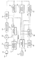
図1は、本発明の超音波診断画像処理装置をブロックダイヤグラムにより説明している。図2、3、4、および5は、超音波画像処理用途に有益に適用可能な高調波エコーのいくつかの特性を説明する。そして、図6および7は、図1の例の挙動を説明するのに使用された通過帯域特性曲線である。図8は、本発明例の典型的な基本および高調波周波数通過帯域を説明する。図9は、図1の例における使用に適当なFIRフィルタ構造を説明する。図10は、本発明好適例の一部のブロックダイヤグラムによる説明である。図11は、図10の例の正規化段階の操作を説明する。図12は、図10の例のフィルタで使われた乗算器累算器の1つのブロックダイヤグラムである。図13は、図10の例の典型的な基本および高調波周波数通過帯域を説明する。図14は、1つの超音波画像への基本および高調波信号成分のブレンドを説明する。そして、図15は、ブレンドされた画像形成に使用された時間変化フィルタの通過帯域を説明する。
【0008】
【発明の実施の態様】
最初に図1を参照すると、本発明により構成された超音波診断画像処理装置が、ブロックダイヤグラム方式で示されている。中央制御器120は、発信周波数制御117に命令し、所望の発信周波数帯域を発信させる。発信周波数帯域の変数、ftr、は、発信周波数制御117に送られ、超音波プローブ110の変換器112に、基本周波数帯域の超音波を発信させる。構成例においては、ほぼ1.67MHzの中心周波数を持つ周波数帯域が、発信される。これは、通常2.5MHzからそれ以上の範囲であった従来の発信画像処理周波数よりも低い。しかしながら、3あるいは5MHzの典型的な発信周波数の使用は、6および10MHzの高調波を作成する。高周波数は、低周数よりも身体を通る間により大きく減衰されるので、これらの高周波数の高調波は、それらがプローブに戻る間に、相当な減衰を経験するであろう。高調波信号は発信波が組織中を進行する間に発生するので、変換器からの往復による減衰を経験する基本周波数信号が減衰するほどは衰退しないのではあるが、これが侵入深さを減じ、そしてより大きな画像処理深さでの画像の質を劣化させる。この問題を克服するために、説明例における中心発信周波数は、5MHz 以下、好ましくは2.5MHz以下であり、これによって深さ依存減衰の影響を受けにくい、より低い周波数の高調波を形成させ、そしてより深い場所での高調波画像処理を可能とする。1.67MHzの発信基本周波数は、説明例において、3.34MHzの第二高調波の戻り信号を作成する。勿論、希望する侵入深さ、変換器および超音波装置の感度に十分な考慮を払うことにより、いかなる周波数の超音波でも使用することができることは理解されるであろう。
【0009】
プローブ110のアレー変換器112は、超音波エネルギーを発信し、この発信に応答して戻ったエコーを受信する。変換器の応答特性は、一つは基本発信周波数周辺、もう一つは受信通過帯域における高調波周波数付近のものという、2つの通過帯域を示す。高調波画像処理のためには、発信基本周波数および受信高調波通過帯域の両方を含む通過帯域を持つ広帯域変換器が好ましい。変換器は、図6に示すような応答特性を示すように製造され調整され、そこでは応答特性曲線の低い方のこぶ60は、発信基本周波数fr付近に中心があり、そして高い方のこぶ62は、応答通過帯域の受信高調波周波数fr付近に中心がある。しかしながら、単一主要特性曲線64は、プローブを、高調波画像処理および従来の広帯域画像処理の両方に適することを可能にするので、図7の変換器応答特性曲線の方が好ましい。特性曲線64は、発信基本周波数ftを包含し、そして周波数fLとfcの間に含まれ、そして周波数frの付近に中心がある高調波の受信通過帯域をも包含する。上述したように、1.67MHzの低い基本発信周波数は、3.34MHzの周波数の高調波の戻りエコー信号を形成する。おおよそ2MHzの応答特性曲線64は、これらの基本および高調波周波数にとって適当である。
【0010】
身体の組織および細胞は進行中に発信された基本周波数信号を変化させ、そして、戻りエコーは、本来発信された基本周波数の高調波成分を含む。図1において、これらのエコーは、変換器アレー112により受信され、T/Rスイッチ114を通じて転送され、そしてアナログ・ディジタル変換器115によってディジタル化される。A/Dコンバーター115のサンプリング周波数fsは、中央制御器によって制御される。サンプリング理論によって示された望ましいサンプリング速度(rate)は、受信通過帯域の最も高い周波数fcの少なくとも2倍であって、先の例における周波数においては、少なくとも8MHz程度となる。最小限要求されるものよりも高いサンプリング速度も好ましい。
【0011】
個々の変換器素子からのエコー信号試料は、遅延され、ビーム形成器116によって合計されて、位相のそろった(coherent)エコー信号を形成する。位相のそろったディジタルエコー信号は次いで、ディジタルフィルタ118によってろ過される。この例において、発信周波数ftは、受信器に関係が無く、従って受信器は、発信された帯域と違う周波数帯域を自由に受信することができる。ディジタルフィルタ118は、図7の周波数fLとfcで区切られた通過帯域中の信号を帯域通過ろ過し、そしてまた、周波数帯域をより低いもしくはベース帯域周波数範囲に移動することができる。ディジタルフィルタは、上記の例において、1MHz通過帯域を有し、そして3.34MHzの中心周波数のフィルタとすることができる。 好ましいディジタルフィルタは、図9に示すような、一連の乗算器70-73と累算器80-83である。この配置は、中央制御器120によって制御され、ディジタルフィルタの特性曲線を制御する乗数の重み付けとデシメーション(decimation)の制御を行う。好ましくは、この配置は、有限インパルス応答(FIR)フィルタとして働くよう制御され、フィルタリングとデシメーションの両方を実施する。例えば、第一段階出力1のみが、4:1デシメーション割合の4タップFIRフィルタとして働くよう制御することができる。時間的に不連続なエコー試料Sが第一段階の乗算器70に転送される。試料Sが転送されると、それらに中央制御器120によって与えられた重みが乗算される。これらの積のそれぞれは、4個のこのような積が累積(加算)されるまで、累算器80に保存される。次に出力信号が、第一段階出力1で作成される。累積された合計は4つの重み付けされた試料からなるので、この出力信号は、4タップFIRフィルタによってろ過される。4試料分の時間が出力信号を作成するのに必要なので、4:1デシメーション比が実現する。1つの出力信号が、4つの入力試料毎に形成される。累算器は清算され、このプロセスが繰り返される。デシメーション比が高く(出力信号間の間隔が長く)なると、フィルタの有効なタップ数は多くなることが分る。
【0012】
必要に応じ、時間分割された試料は、遅延要素τによって遅延され、4つの乗算器70−73に適用され、乗算され、そして累算器80−83に累積される。それぞれの累算器が2つの積を累積した後、4つの出力信号は、一つの出力信号に結合される。即ちフィルタは、2:1デシメーション比を有する8タップフィルタとして動作している。デシメーションなしならばこの配置は、4タップFIRフィルタとして動作することができる。フィルタはまた、エコー信号を全ての乗算器に同時に転送することにより、そして重み付け係数を選択的に時間順にすることにより動作させることもできる。中央制御器の制御下で、フィルタの重み付けとデシメーション比のプログラミングにより、フィルタ特性曲線の全範囲が可能である。ディジタルフィルタの使用は、異なるフィルタ特性曲線を提供するよう、す速く容易に変化が可能であるという利点がある。ディジタルフィルタは、まず受信基本周波数を通過させ、次に高調波周波数を通過させるようにプログラムすることができる。従って、ディジタルフィルタは、基本そして高調波ディジタル信号の画像または走査線を交互に作成するように操作することができ、信号処理の間にフィルタ係数を単に変化させることによって、時間交互配置されたシーケンスで異なる高調波の走査線を交互に作成するように動作させることができる。
【0013】
図1に戻って、基本周波数でない周波数のみを画像処理するために、ディジタルフィルタ118を中央制御器120によって制御し、基本周波数を除外して、高調波周波数のエコー信号を通過させて処理する。組織からの高調波エコー信号は、ディスプレイ50で二次元超音波画像として表示するために、Bモードプロセッサ37またはコントラスト信号検知器128のいずれかによって検知され、処理される。ディジタルフィルタ118からのろ過されたエコー信号は、従来のドップラー処理のためにドップラープロセッサ130にも転送され、速度およびパワードップラー信号を形成する。これらのプロセッサの出力は、三次元画像作成のために3D画像作成プロセッサ162に転送され、それらは3D画像メモリ164に保存される。これらの三次元表現は、米国特許[出願シリアル番号08/638,710]、および米国特許5,474,073および5,485,842に記載されたようにして実施することができ、後の2つの特許は三次元パワードップラー超音波画像処理技術を説明している。コントラスト信号検知器128、プロセッサ37および130からの信号、および三次元画像信号は、ビデオプロセッサ140に転送され、そこで信号は、使用者が選択した指示に従って、画像表示50上に二次元あるいは三次元表示用に選択される。
【0014】
組織および血液の高調波画像処理は、超音波画像中の近接領域の散乱を減少させうることが見出された。組織の高調波応答効果は、発信波のエネルギー準位に依存すると信じられている。より深い場所に焦点を合わせられたアレー変換器の近くに、発信波成分は焦点を結ばず、近接領域組織で検知可能な高調波応答を発生させるにはエネルギーは不十分となる。しかし、発信波が身体への侵入を続けるので、発信波成分が焦点が合い始めるにつれて、より高強度のエネルギーが高調波効果を発生させる。近接および遠隔の両方の領域が、基本周波数応答を返す一方、これらの信号からの散乱は、高調波周波数帯域に設定されているディジタルフィルタ118の通過帯域によって削除される。組織からの高調波応答が次いで、検知され、表示されるが,一方で近接領域基本周波数応答からの散乱は、表示画像から削除される。
【0015】
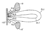
図2、3、4および5は、超音波画像処理に有益に使用することができる高調波戻り信号のいくつかの特性を説明する。これらの特性と、それらの相互作用のいくつかは、まだ科学者の間で充分にそして一般に理解されていないで、まだ研究および議論の対象であると考えられる。図2は、変換器アレー112によって受信された基本周波数と高調波信号の空間的応答、特に主ローブおよびサイドローブを説明する。この例において、アレーは、心臓などの、肋骨の後ろの身体領域を画像処理するように指示されており、そして主ローブは、肋骨10と10'の間に広がって見えている。肋骨の上に横たわっているのは、皮膚と肋骨との間の脂肪層などの組織境界12である。図は、基本信号FL1の主ローブを示し、そして主ローブの両側にはサイドローブ FL2FL3がある。図はまた、基本周波数の高調波の主ローブHL1および高調波主ローブのサイドローブHL2およびHL3を示す。
【0016】
この例において、基本エコーの主ローブは、肋骨10,10'の部分を包含するほど、大きく広がっていることが分る。それゆえに、基本周波数の音響エネルギーは、矢印9によって示されたように、変換器112に反射して戻る。一方この反射のエネルギーのいくらかは、変換器に戻り、直接受信されるが、この例において、反射エネルギーのいくらかは矢印9'に示されるように、組織境界12によって再度反射される。この第2のエネルギー反射は、他の肋骨10'に達し、そこで矢印9"に示されるように再度反射し、変換器112に戻り、受信される。
【0017】
この画像処理手法の意図は、肋骨の後ろの心臓を映像化することにあるので、肋骨によって反射されたこれらのエコーは、超音波画像を汚染する不要の虚像である。矢印9,9'9"の経路をたどるエコーなど、変換器に達する前に、何回も反射された不要のエコーは、多経路虚像(multipath artifact)と呼ばれる。同時にこれらの虚像は、画像「散乱」と呼ばれ、近接領域を、ある場合には全画像を不明瞭にしてしまう。この近接領域の曇りあるいは散乱は、変換器の近くの注目している構造を不明瞭にする場合がある。さらに、多経路虚像は、これらの虚像がたどる長々とした多数の経路のためにより深い部分の画像中に再生成され、より深い場所の関心ある領域に雑音を生じさせ、不明瞭にする場合がある。しかし、超音波画像を作成するのに、高調波戻り信号のみを用いる場合には、この基本周波数からの散乱はろ過され、除去される。受信高調波エコーの主ローブHL1は、基本周波数のローブよりも狭いので、この例において、肋骨10,10'の間を、それらと交差することなしに通過する。 肋骨からの高調波の戻りはなく、肋骨からのいかなる多経路虚像もない。従って、高調波画像は、この例において特に近接領域で、基本周波数画像よりも際だって散乱のないまた曇りのない画像となる。
【0018】
図3は、基本周波数および高調波の戻りの両方の主ローブが肋骨と交差せず、図2で議論した問題が発生しない第二の例を示す。しかしこの例において、肋骨10、10'は、皮膚表面および変換器112に、より近い。主ローブは肋骨と交差しないが、基本周波数のサイドローブ FL2は肋骨に達し、サイドローブエネルギーを、反射経路9に示すように、反射し変換器に戻す。再度これが基本周波数画像に散乱を生じさせる。しかし受信高調波エネルギーの、より小さくより狭いサイドローブHL2は、肋骨に達しない。再度、高調波画像は、基本周波数画像に比べて少ない散乱で表示される。
【0019】
図4は、図2および3のローブを横切る、即ち変換器の軸を横断する、透視図中の基本周波数および高調波のビームパターンを説明する。この図は、基本周波数と第二高調波ビーム形状の相対的な振幅応答を説明する。音響ビームの基本成分の主ローブ(FL1)と第一サイドローブ (FL2)の間の動的応答DRF、および第二高調波成分の主ローブ( HL1)と第一サイドローブ ( HL2)との間の動的応答DRHを説明している。もし主ローブによる応答を、所望の信号応答とみなし、サイドローブによる応答を散乱あるいはノイズとするならば、高調波の信号対ノイズ比の方が基本周波数のものよりも大きい。即ち、同じ発信の対応する基本周波数画像中よりも、高調波画像中の方が相対的にサイドローブ散乱は小さい、あるいは DRH>DRF である。
【0020】
図5は、基本および高調波信号の特性の別の比較を説明しており、それは基本および第二高調波の周波数における身体中の、より深い場所Zから出るエネルギー(音響圧力Pの単位で)の相対的な量である。Fund.で表示された曲線は、基本周波数における進行した音響エネルギーが増強(buildup)されたことを示す。曲線はアレー変換器の焦点で頂点に達することが分るが、焦点領域の前の浅い部分に、感知されるほどの量の基本エネルギーがそれでもなお存在することが分る。比較すると、これらの浅い領域に進行した高調波周波数では、相対的にずっと小さいエネルギーと小さいエネルギー増強が存在する。従って、多経路反響および他の異常に使用されたエネルギーが小さいので、同じ発信からの基本周波数エコーの戻りの画像処理よりも、高調波の画像処理の方が、近接領域散乱は小さい。
【0021】
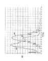
図8が1.67MHzの音波の4サイクルの発信信号における本発明の典型的な図1の例のディジタルフィルタおよび受信信号帯域を説明する。多数サイクル発信は、発信信号の帯域幅を狭くする;サイクルの数が多いほど、帯域幅は狭くなる。この発信に応答して、変換器112は、帯域幅90で基本信号を受信し、それは1.67MHzの発信周波数で頂点に達するのが分る。基本周波数帯域が低下するにつれて、高調波帯域92が立ち上がり、3.34MHzの高調波周波数で再びピークを示すのが分る。受信信号は、通過帯域特性曲線94でディジタルフィルタに転送され、それは3.34MHzの高調波周波数の周辺に中心があるのが分る。図8が示すように、この通過帯域は本質的に、高調波信号をさらなる処理と画像形成のために通過させる一方、基本周波数の信号を抑制する。このようにして心臓を画像処理するとき、心臓の心臓内組織の高調波応答は、非常に実質があり、そして心臓の高調波組織画像は明瞭に識別された心臓内の境界を示すことが見出された。
【0022】
広帯域信号中の基本周波数を分離し高調波周波数のみを残すなど、受信エコー情報から高調波信号を分離抽出するのに、ろ過以外の他の信号処理技術を用いることもできる。例えば、米国特許[出願SN08/728,318]は、2パルス技術を開示し、これにより、それぞれの走査線に、急速に連続して反対位相の連続基本周波数パルスが照射される。結果として生じるエコーが2つのパルスから受信され、空間基準で結合されるとき、基本周波数は除去され、そして非線型のあるいは高調波周波数が残る。従って、高調波周波数は、フィルタ回路の必要なしで広帯域エコー信号から分離される。
【0023】
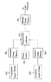
図10は本発明の好適例の一部、ビーム形成器出力から画像表示装置までを、ブロックダイヤグラムにより示している。この例は、組織および血流の高調波画像を作成するばかりでなく、病状の画像化が困難な患者を画像処理するときに生じる従来の画像処理装置の信号脱落の欠点をも克服する。その上、この例においては、スペックルとして知られている位相のそろった超音波画像の虚像を減少させる。図10において、説明例のプロセッサが完全にディジタルなので、ブロックダイヤグラムのブロックに接続する全ての信号およびデータ・ラインは、多導体ディジタルデータ経路を表している。ビーム形成器116からの走査線エコーデータは、並列で図10において説明したプロセッサの2つのチャネル30a、30bに送られ、その一つが高周波数チャネル、そしてもう一方が低周波数チャネルである。プロセッサのそれぞれのチャネルは、正規化(normalization)段階32,132を有し、走査線データにそれぞれの試料毎にスケール因子を積算し、それぞれの試料が戻る身体の深さによって異なる利得あるいは減衰を形成する。各チャネルのスケール因子は、好適例においてはディジタルメモリである係数回路32、132により作成されるか、保存されていた正規化係数により与えられる。積算係数は、一連の走査線エコーに沿って変化するので、深さ依存利得あるいは減衰が作成される。
【0024】
正規化段階の機能は、2つある。一つは、走査深さにより拡張される変換器開口の効果を補償することである。増加する数の変換器からの信号が、深さが増加すると共に使われるので、合計されたビーム形成された信号の大きさは、増加する。この増加はビーム形成プロセスに、回路が加えられる比率と比例する正規化段階における利得の減少(減衰の増大)によって相殺され、結果として生じるエコーシーケンスは、変化する開口によって影響されないこととなる。
【0025】
正規化段階の第2の機能は、2つのチャネル30a、30bの公称(nominal)信号振幅を等しくすることである。2つのチャネルの通過帯域の公称信号振幅は、好ましくは等しく、通過帯域が合計され全高調波通過帯域が作成された後に、当初の相対的信号レベルが保たれる。しかし超音波信号には、周波数によって変化する深さ依存減衰があるので、高周波数信号は低周波数よりも深さによる減衰が大きい。この深さ依存減衰を考慮して、正規化段階の係数は、深さと共に増加する信号利得を与える。2つのチャネルが異なる周波数通過帯域を使うので、2つのチャネルの深さ依存利得は互いに相違する。特に、高周波数通過帯域チャネル用の利得増加の割合は、低周波数通過帯域チャネルのものよりも大きい。これを図11で説明するが、説明のために、2つの成分に分けられた、高周波数通過帯域チャネルの正規化利得特性曲線が示されている。深さ依存特性曲線200は、チャネルにおける増加開口の効果を相殺し、そして深さ依存特性曲線202は、深さ依存信号減衰を補償する。低周波数通過帯域チャネルも、深さ依存利得特性を有するが、より低い周波数の異なる減衰割合のために異なる特性曲線202となる。高周波数通過帯域チャネルは、より高い周波数によるより急速な減衰割合のために、同様の、しかしより急速に増加する深さ依存利得特性曲線を有する。それぞれの深さ依存利得特性曲線202が、そのチャネルが使用する特定の周波数通過帯域用の深さ依存利得効果を相殺するように選択される。
【0026】
好適例において、係数回路の係数は、2つの特性曲線200,202を組み合わせた利得または減衰特性曲線を適用する。好ましくは、係数メモリ32,132は、走査ヘッド特性、あるいは処理される信号の種類(2D、あるいはドップラー)に適合するように、メモリアドレッシングと共に変化する多結合利得曲線を記憶する。利得変化の割合は、係数がそれぞれの正規化段階30,130の乗算器のために変化する割合によって制御することができる。
【0027】
チャネルの正規化されたエコー信号は、各チャネルの直角位相帯域通過フィルタ(QBP)に転送される。直角位相帯域通過フィルタは、3つの機能を行う:RF走査線データの帯域制限、走査線データの同相のそして直角位相の対の作成、およびディジタル試料速度の削減である。各QBPは、2つの別々のフィルタからなっており、一つは同相試料( I )を作成し、そして他方は直角位相試料(Q)を作成し、それぞれのフィルタは、FIRフィルタを実行する複数の乗算器−累算器(MAC)によって構成されている。1台のこのようなMACが、図12に示されている。走査線データのエコー試料がディジタル乗算器210の1つの入力に送られると、係数が別の乗算器入力に送られる。エコー試料と重み付け係数の積は累算器212に保存され、前の積と累積される。他のMACは、異なる位相のエコー試料を受け取って、同様に重み付けされたエコー試料を累積する。いくつかのMACが累積した出力は結合され、そして最終的に累積された積は、ろ過されたエコーデータからなっている。累積された出力が採取される割合が、フィルタのデシメーション比を設定する。フィルタの長さは、デシメーション比とフィルタを形成するのに使用されたMACの数の積であり、累積された出力信号を作成するのに使用される入力エコー試料の数を決定する。フィルタ特性は、乗算の係数値によって決定される。異なるフィルタ機能のための異なる係数の組は、係数メモリ38,138に保存され、MACの乗算器に転送され、選択された係数が適用される。MACは、サインおよびコサインで表示される係数で、受信エコー信号を効率的に巻回し(convolve)、直角位相関係にある出力試料を作成する。
【0028】
Iフィルタを形成するMAC用の係数は、サイン機能を実行し,一方Qフィルタ用の係数は、コサイン機能を実行する。帯域通過フィルタリングのために、活性QBPsの係数は、さらに周波数シフトされて、サイン(Iについて)とコサイン(Qについて)関数によって、直角位相試料の帯域通過フィルタを形成する低帯域通過フィルタ機能を実行する。この例において、チャネル30aのQBP1は、第一の、低周波数通過帯域の走査線データのIおよびQ試料を作成し、チャネル30bのQBP2は、第二の、高周波数通過帯域の走査線データのIおよびQ試料を作成する。従って、当初の広帯域エコー信号のスペクトルは、高周波数帯域と低周波数帯域に分割される。脱落およびスペックル除去工程を完結するために、チャネル30aのQBP1によって作成された通過帯域中のエコーデータは、検知器401により検知され、検知された信号は合計器48の1つの入力に転送される。好適例において、検知は、下記アルゴリズム
【0029】
( I2+ Q2)1/2
【0030】
を計算することによってディジタル方式で実行される。チャネル30bのQBP2によって作成された補足的通過帯域中のエコーデータは、検知器402によって検知され、これらの検知された信号は合計器48の第二の入力に転送される。2つの通過帯域の信号が合計器48によって結合されるとき、2つの通過帯域の非相関信号脱落およびスペックル効果が少なくとも部分的に除去され、信号から作成された2D画像中の信号脱落およびスペックル虚像を減少させる。
【0031】
各サブチャネル中の検知器に続いて、係数メモリ421,422から重み付け係数を受ける乗算器441,442によって形成される利得段階がある。この利得段階の目的は、最良のシステム性能となるよう超音波装置におけるアナログおよびディジタル利得のバランスを取ることである。エコー信号経路中のいくつかの利得は超音波装置によって自動的に実行されるが,他方その他の手動利得制御およびTGC利得などは、使用者によって制御することができる。装置はこれらの利得を配分し、ビーム形成器のADCs(アナログからディジタルへの変換器)の前のアナログ利得を、ADCsの動的入力範囲が最適になるように調整する。ディジタル利得は、画像の明度が最適となるよう調整される。2つの利得は共に、使用者によって行われた利得調整の変更を実行する。
【0032】
好適例において、乗算器441,442によって走査線信号に付与された利得は、チャネル中の先の正規化段階34,134の利得と協調するよう選択される。各正規化段階の利得は、造影剤あるいは高調波画像処理からの強信号が受信されたときに生じるような、QBPsでの飽和水準の達成を阻止するように選択される。飽和水準を避けるために、正規化段階の最大利得が制御され、そしてこの制御のために課されたいかなる減少も、続く乗算器441,442の利得によって回復される。これらの乗算器によって実施される利得機能は、ディジタル信号処理経路に沿ったどこにおいても実行できる。それは以下に論じる圧縮曲線の傾きを変化させることによって実行することができる。それは例えば、正規化段階で与えられた利得と関連して実行することもできる。しかしこの後者の実施は、上記した飽和制御を実施する能力を削除してしまう。本発明者らは、この利得機能の実行能力が、検知の後に与えられるときに、好適例では検知後の乗算器の使用によって、消去されることを見いだした。
【0033】
利得段階441,442により作成された信号は、ディスプレイ50によって与えられるよりも一般に大きいダイナミックレンジを示す。その結果、乗算器の走査線信号は、ルックアップテーブルによって適当なダイナミックレンジに圧縮される。一般に、対数圧縮プロセッサ461,462によって示されるように、圧縮は対数圧縮である。それぞれのルックアップテーブルの出力は、信号入力値の対数に比例する。これらのルックアップテーブルは、圧縮曲線および表示装置に送られる走査線信号の明度およびダイナミックレンジを変化させられるようにプログラム可能である。
【0034】
エコー信号の基準化に対数圧縮を使用することが、黒レベル成分のエコーの程度および数の劣化により、信号ダイナミックレンジの基線(黒)レベル近くの低レベル信号に悪影響を及ぼしうること、即ちそのコヒーレント超音波エネルギーのスペックル効果から生じる破壊的障害の顕在化、を本発明者らは見いだした。エコー信号が表示されるとき、それらの多くは黒レベルにあり、そして画像からは検知されないか欠落してしまうであろう。図10の例はこの問題を2つのチャネル30a、30b中に、エコー信号であって分離され、部分的に非相関化(decorrelate)されたものを作成することにより軽減している。この例では、図13に示すように、2つの異なる通過帯域にエコー信号成分を分割することによってエコー信号形状(version)を部分的に非相関化する。2つの通過帯域は完全に分離することができ、またはこの例に示すように、重なってもよい。この例において、低通過帯域300aは、3.1MHzの周波数付近に中心があり、高通過帯域300bは3.3MHzの周波数付近に中心があり、中心周波数の隔たりは200kHZにすぎない。この小さい分離でさえも、1つの通過帯域の黒レベル信号脱落が、しばしば他の通過帯域でその対応する成分と、周波数について整列しないように、2つの通過帯域の信号成分を十分に非相関化するのに十分であることが分かった。従って、同じエコー信号のこれら非相関化されたレプリカが、合計器48により結合されるとき、信号脱落およびスペックル虚像は、著しく減少するであろう。心内膜などの、身体の深い部位の微細構造を画像化しようと試みるとき、これは特に重要である。心内幕の高調波画像は、図10の例の虚像除去効果によって著しく改良される。
【0035】
先に議論したように、図13の2つの通過帯域300a、300bの信号利得は、合計後の、当初の信号レベルを保存するように調整可能である。しかし好適例においては、低周波数通過帯域は、図13に示すように、高周波数通過帯域よりも狭いダイナミックレンジで処理される。これは、低周波数通過帯域(それは、高周波数帯域より多くの基本周波数成分を含んでいる)の基本周波数の寄与を抑制する効果を持つ。これは、異なる圧縮特性の成分として、広帯域信号の分割通過帯域への分離後に、対数圧縮プロセッサ461,462で、またはチャネル30a、30b中の他の行程で実施される。
【0036】
合計器48の出力の処理されたエコー信号は、低周波通過フィルタ52に転送される。この低周波通過フィルタは、QBPsのように、FIRフィルタを実行するよう配置された可変係数を有する乗算器−累算器の組み合わせによって構成され、フィルタ特性を制御する。低周波通過フィルタは、2つの機能を実施する。ひとつはサンプリング周波数と処理されたエコー信号からの他の不要な高周波数成分を除去することである。第二の機能は、表示画像中のエイリアシングを防止するために、走査線データ速度をディスプレイ50の垂直ライン密度に合わせることである。FIRフィルタは、選択的にデシメイトし、あるいは走査線データを内挿することによってこの機能を実行する。ろ過されたエコー信号は次に、画像メモリ54に保存される。もしも、走査線がまだ走査変換されていないならば、即ちそれらがr、θ座標を有するならば、走査線は、走査変換器およびグレースケールマッピングプロセッサ56により直線(rectilinear)座標に走査変換される。もしも、走査変換がその前の工程で実施されているならば、または走査変換が画像データにとって不要ならば、プロセッサ56は、ルックアップテーブルプロセスによって単にエコーデータを所望のグレースケールマップに変換する。画像データは次いで、最終画像メモリに保存するか、あるいはディスプレイ50の駆動に適当な表示信号に変換するために、ビデオディスプレイドライバー(示されていない)に送られる。
【0037】
ディジタルフィルタの迅速なプログラミング可能性によって、上記処理は、時間交互配置方式により、二つの通過帯域のそれぞれについて一列の信号を交互に作成することで、チャネル30a、30bのいずれか一つを利用して、走査線からのエコーデータを二度処理する具体例において、実行することができると理解される。しかし、2つの平行チャネルの使用は、2倍の処理速度があるので、実時間で時間多重通信例の2倍のフレーム速度での高調波画像の作成を可能にする。
【0038】
高周波数信号から作成された高調波画像は、エコー信号の戻る部位が身体中より深くなるにつれて、深さ依存減衰により劣化する場合がある。より低周波数の基本信号は、減衰がより少ないので、より深い部位でより良好な信号対雑音比を示す場合がある。図14の例は、1つの画像中に基本周波数と高調波画像データをブレンドすることによってこの特性を利用している。例えば、基本周波数から心臓の通常の組織画像を作成することができ、この基本周波数組織画像に心臓の高調波組織画像を重ね合わせ、この複合画像中に、心臓内境界をより明瞭に識別することができる。2つの画像、即ち一つは基本周波数成分からのもの、そしてもう一つは高調波周波数成分からのものは、基本および高調波周波数の間でディジタル・フィルタ118を交互に切り替えることにより、基本および高調波画像を別々に組み合わせて、または2つの通過帯域を有する図10の平行する二つのフィルタ、一組は基本周波数を通し、他の組は、高調波周波数を通す、を使うことによって形成することができる。図14で、チャネル30aのフィルタは、基本信号周波数を通すように設定され、そしてこのチャネルを通過したエコー信号は、基本画像メモリ182に保存される。それに対応して、高調波信号周波数は、チャネル30bを通り、高調波画像メモリに保存される。基本および高調波画像は次いで、ブレンド制御192の制御のもとで、比例結合器190によってブレンドされる。ブレンド制御192は自動的に、事前にプログラムされたブレンドアルゴリズムを実行するか、または使用者による指示を実行する。例えば、比例結合器190は、浅い深さで高調波画像からのエコーデータのみを使用し、次いで中間の深さでは両方の画像からのエコーデータを結合し、そして最後に深い部位では基本画像のエコーデータのみを使用して混合画像を作成する。これは、中間深さにおいて1つのデータの型からもう一方への滑らかな移り変わりを実現しつつ、浅い部位での高調波エコーデータの散乱が少ない利益、深い部位から受信された基本周波数エコーのより大きい貫通能力と信号対雑音比を結合するものである。例えば予め定められた深さで1つのデータの型からもう一つのものに単に切り替えたり、または表示される画像領域の輪郭を一つのデータの型で描き、残りの画像を他方のデータの型を使用して表示するなどの、他の結合アルゴリズムもまた可能である。
【0039】
2つの平行するフィルタを使って画像構成前に成分をブレンドし、それによって、高調波エコー信号の制御可能成分を基本周波数信号に加え、結果として生じる画像の画質を改良することも可能である。このような例では、基本および高調波画像を別個のメモリに保存する必要性をなくすることができ、直接信号成分をブレンドされた画像メモリへと処理する。
【0040】
ブレンド画像を作成する第3の手法は、深さ依存、時間変化フィルタを通して画像の各走査線を受信することである。このようなフィルタは、例えば、米国特許第4,016,750に示されるように、深さ依存減衰の存在下において、受信エコー信号の信号対雑音比を改良するものとして公知である。ブレンドされた基本および高調波画像作成のために、時間変化フィルタの通過帯域210は、最初エコー信号は浅い部位から受信が始まるので、図15に示すように、高調波周波数fhを通過させるよう設定される。より深い部位において、基本信号成分で画像を補い始めるのが望ましくなったとき、通過帯域210はより低い周波数に移動し、図15の通過帯域212に示されるように、最終的に基本周波数ffに移動する。図9に示すようなディジタルフィルタにおいては、通過帯域周波数の変化は、フィルタ係数を時間と共に変化させることによって実行される。この移動をフィルタが実行するとき、所望により、通過帯域が、最終的に最深画像深度で基本周波数のみを通過させるまで、通過帯域はわずかな高調波周波数と多くの基本周波数を通過させる。このような時間変化フィルタを通して各走査線を受信することによって、結果として生じる画像の各ラインは、近接領域(浅い部位)では高調波周波数、遠隔領域(最も深い部位)では基本周波数、そしてその中間では両者のブレンドからなることとなる。
【0041】
ブレンドされた画像を作成するための第4の手法は、各走査線に沿って2度発信し、受信することである。1つの発信は、基本周波数のものであって、そして高調波周波数エコーの受信が次に続く。他の発信は、基本周波数のものであり、基本周波数の受信が次に続く。2つの基本発信周波数は同じであるが、希望する場合には、異なる基本周波数でもよい。高調波と基本周波数のエコーは次いで、所望の割合で走査線に沿って結合され、ブレンドされた走査線を形成し、このような走査線の画像領域が作成され、ブレンドされた画像を形成する。「医療用超音波パワー運動画像処理方法」なる発明の名称の米国特許[出願08/655,394]に記載された、プロセッサにより、受信高調波組織エコー信号を処理することにより、運動している組織の高調波組織画像を形成することもできる。
【0042】
従って、本発明は、身体組織および体液の超音波への非線形応答を、基本周波数信号を発信し、非基本、好ましくは高調波、周波数の組織からのエコー信号を受信して、非基本周波数のエコー信号を検知し、非基本周波数エコー信号からの組織および体液の画像を形成する事により画像処理する超音波画像処理装置を包含する。ここに述べられた本発明の原則は、より高次のおよび分数調波の周波数にも等しく適用できるので、本明細書に使用されている高調波なる語は、第二高調波よりもさらに高次の高調波周波数も、分数調波も意味している。
【0043】
本発明は、発信周波数と異なる応答周波数による超音波診断画像処理方法を開示するもので、本発明は、発信基本周波数の高調波エコー成分から超音波画像を作成する超音波診断画像処理装置および方法に関する。好ましくは、基本周波数信号を除去して画像処理するために、高調波エコー成分を通過させるのに、プログラム可能なディジタルフィルタが使用される。好適例においては、虚像が、高調波信号の非相関レプリカを作成することにより除去され、それは次いで結合されて画像処理に使用される。高周波数エコー信号の深さ依存減衰の存在下で画像を作成するために、基本および高調波エコー信号の両方が処理され、基本および高調波エコー信号の両方の成分からブレンドされた画像を作成するのに使用される。
【0044】
本発明の態様は以下のとおりである。
1.体内構造の高調波応答を画像処理する超音波診断画像処理装置であって、基本周波数で体内に超音波エネルギーを発信する手段;該発信超音波エネルギーに応答し、該基本周波数の高調波周波数での超音波エコー信号を受信する手段;および、該高調波エコー信号から超音波画像を作成する手段からなる超音波診断画像処理装置、2.該発信する手段および該受信する手段が、超音波変換器プローブからなる前記1の超音波診断画像処理装置、3.該超音波変換器プローブが、基本周波数の超音波エネルギーを発信し、該基本周波数の高調波の超音波エコー信号を受信するための複数の変換器素子からなる前記2の超音波診断画像処理装置、4.該変換器素子が、該基本周波数と、該基本周波数の高調波の両方を包含する応答特性を示す前記3の超音波診断画像処理装置、5.該基本周波数の高調波の超音波エコー信号を受信する該手段が、該基本周波数を除外した該高調波周波数を識別する通過帯域を有するフィルタからなる前記1の超音波診断画像処理装置、6.該フィルタが、プログラム可能なディジタルフィルタからなる前記5の超音波診断画像処理装置、7.該超音波画像を作成する手段が、Bモードプロセッサを含む前記1の超音波診断画像処理装置、8.該Bモードプロセッサが、該高調波エコー信号の包絡線(envelope)を検知するための振幅検知器を有する前記7の超音波診断画像処理装置、9.該構造が、身体の生来存在する構造からなる前記1の超音波診断画像処理装置、10.該生来存在する構造が、身体の組織および細胞からなる前記9の超音波診断画像処理装置、11.身体内部の高調波応答から超音波画像を作成する方法であって:基本周波数で体内に超音波エネルギーを発信し;該基本周波数の高調波周波数の超音波エコー信号を受信し;そして、該高調波エコー信号を処理して、超音波画像表示信号を作成し;そして、該超音波画像表示信号を表示する、以上の段階からなる超音波画像を作成する方法、12.発信する段階および受信する段階が、変換器アレーを有する超音波プローブを使用して、基本周波数超音波エネルギーを発信し、高調波エコーを受信することからなる前記11の方法、13.超音波プローブを使用する段階が、同じ変換素子で、基本周波数超音波エネルギーを発信し、高調波エコー信号を受信する段階からなる前記12の方法、14.該基本周波数の高調波周波数の超音波エコー信号を受信する段階が、該基本周波数を除外して該基本周波数の該高調波周波数の信号を通過させるフィルタにより、受信超音波エコー信号を通過させることからなる前記11の方法、15.該処理するステップが、該高調波エコー信号をBモード処理することからなる前記11の方法、16.該Bモード処理の段階が、該高調波エコー信号を振幅検知する段階からなる前記15の方法、17.虚像を減少させた、体内構造の高調波応答の超音波画像を作成するための超音波診断画像処理装置であって:基本周波数で身体内に超音波エネルギーを発信する手段;該発信超音波エネルギーに応答して、該基本周波数の高調波周波数の超音波エコー信号を受信する手段;該高調波超音波エコー信号を処理し、該エコー信号の少なくとも部分的に非相関化されたレプリカを形成する手段;該非相関化されたレプリカを結合させて、虚像を減少させた高調波エコー信号を作成する手段;および、該虚像を減少させた高調波エコー信号を利用して、超音波画像を作成する手段、からなる超音波診断画像処理装置、18.該虚像が、脱落虚像からなる前記17の超音波診断画像処理装置、19.該虚像が、さらにスペックル虚像からなる前記18の超音波診断画像処理装置、20.該処理するための手段が、該高調波超音波エコー信号の成分を、異なる中心周波数を有する2つの通過帯域に分割する帯域通過フィルタからなる前記17の超音波診断画像処理装置、21.該処理するための手段が、さらに、該通過帯域のそれぞれに、高調波超音波エコー信号を検知する検知器を有する前記20の超音波診断画像処理装置、22.該処理するための手段がさらに、検知された高調波超音波エコー信号を対数圧縮する対数圧縮プロセッサからなる前記21の超音波診断画像処理装置、23.該処理する手段が、高調波超音波エコー信号を受信するために接続する入力と、該結合手段に接続する出力をそれぞれが有する二平行チャネルを有し、ここに該チャネルのそれぞれが、他方のチャネルのフイルタ特性と異なるフィルタ特性を持つ帯域通過フィルタを有する前記17の超音波診断画像処理装置、24.該フィルタ特性が、フィルタのピーク応答周波数である前記23の超音波診断画像処理装置、25.該フィルタ特性が、フィルタの中心周波数である前記23の超音波診断画像処理装置、26.該チャネルのそれぞれがさらに検知器を有する前記23の超音波診断画像処理装置、27.該チャネルのそれぞれがさらに、対数圧縮プロセッサを有する前記26の超音波診断画像処理装置、28.該処理する手段が、該高調波超音波エコーを、等しくないダイナミックレンジの2つの通過帯域に分割する手段からなる前記17の超音波診断画像処理装置、29.該2つの通過帯域が、低周波通過帯域と高周波通過帯域からなり、そしてここに、該低周波数通過帯域のダイナミックレンジが、該高周波数通過帯域のダイナミックレンジよりも小さい前記28の超音波診断画像処理装置、30.該処理する手段がさらに、該通過帯域のそれぞれのダイナミックレンジを異なってマッピングする手段からなる前記29の超音波診断画像処理装置、31.虚像を減少させた高調波超音波画像を作成する方法であって:基本周波数の超音波エネルギーを発信し;該基本周波数の高調波周波数の超音波エコー信号を受信し;該信号の非相関化レプリカを作成するために、該高調波エコー信号を処理し;該非相関化レプリカを結合させて、虚像を減少させた高調波エコー信号を作成し;そして、該虚像を減少させた高調波エコー信号を利用して超音波画像を作成する、以上の段階からなる高調波超音波画像を作成する該方法、32.該高調波エコー信号を処理する段階が、該高調波エコー信号の成分を2つの異なる通過帯域に分割することからなる前記31の方法、33.該高調波エコー信号を処理する段階が、該高調波エコー信号成分を、2つの等しくないダイナミックレンジの二つの異なる通過帯域に分割することからなる前記32の方法、34.該高調波エコー信号を処理する段階が、該高調波エコー信号成分を、与えられたダイナミックレンジの高周波数通過帯域と、該与えられたダイナミックレンジよりも小さいダイナミックレンジの低周波数通過帯域に分割することからなる前記33の方法、35.身体内構造の高調波超音波画像を作成する超音波診断画像処理装置であって:体内に基本周波数の超音波エネルギーを発信する手段;該発信超音波エネルギーに応答し、該基本周波数、および該基本周波数の高調波周波数の超音波エコー信号を受信する手段;および、該受信基本周波数エコー信号および高調波周波数エコー信号を処理し、該基本周波数と高調波周波数エコー信号の両成分から形成された超音波画像を作成する画像プロセッサからなる超音波診断画像処理装置、36.該受信する手段が、分割された基本および高調波周波数エコー信号を作成する手段を有する前記35の超音波診断画像処理装置、37.該受信する手段が、高調波周波数エコー信号の少なくとも一部を除外した基本周波数エコー信号を作成し、少なくとも一部の基本周波数エコー信号を除外した高調波周波数エコー信号を作成するフィルタを含む前記36の超音波診断画像処理装置、38.該画像プロセッサが、該画像の近接領域で高調波エコー信号をより多く、そして該画像の遠隔領域で基本周波数エコー信号をより多く使用する手段からなる前記35の超音波診断画像処理装置、39.超音波エネルギーの深さ依存減衰を示す体内構造の高調波応答を画像処理する超音波診断画像処理装置であって:5MHzまたはそれ以下の基本周波数の超音波エネルギーを体内に発信する手段;該発信超音波エネルギーに応答して、10MHzまたはそれ以下の、該基本周波数の高調波の超音波エコー信号を受信する手段;および、該高調波エコー信号から超音波画像を作成する手段、からなる超音波診断画像処理装置、40.該発信手段が、2.5MHzまたはそれ以下の基本周波数で体内に超音波エネルギーを発信し;そして、該受信手段が、5MHzまたはそれ以下の該基本周波数の高調波周波数の超音波エコー信号を受信する前記39の超音波診断画像処理装置、41.該発信手段が、2MHz以下の基本周波数の超音波エネルギーを体内に発信し;そして、該受信手段が、4MHz以下の該基本周波数の高調波周波数の超音波エコー信号を受信する前記39の超音波診断画像処理装置、42.該受信手段が、該基本周波数を除外して該高調波エコー信号を通過させるようにプログラムされたプログラム可能ディジタルフィルタを有する前記39の超音波診断画像処理装置、43.組織の非線型応答を画像処理する超音波診断画像処理装置であって:体内に基本周波数の超音波エネルギーを発信する発信器;超音波エネルギー発信後に組織から戻ったエコーに応答して、組織の非線型応答を超音波で表す信号を分離する受信器;および、該非線型応答信号から超音波画像を作成する画像プロセッサ、からなる超音波診断画像処理装置、44.該受信器が、組織の非線型応答を超音波で表す信号を分離するフィルタ回路を有する前記43の超音波診断画像処理装置、45.該受信器が、組織中の同じ空間位置からの多数のエコーの受信に応答して、該多数のエコー信号を結合し、組織の非線型応答を超音波で表す信号を分離する信号プロセッサを有する前記43の超音波診断画像処理装置、46.組織の非線型超音波応答が、該基本周波数の二次あるいはさらに高次の高調波からなる前記43の超音波診断画像処理装置、47.組織の非線型超音波応答が、該基本周波数の分数調波を有する前記43の超音波診断画像処理装置。
【0045】
【発明の効果】
基本周波数でない高調波周波数エコー成分を超音波画像処理に有効に使用する方法および装置が提供される。高調波ビームを使用することにより、肋骨などの狭い口を通しての画像処理のときの散乱を減少させ、高調波ビームのサイドローブレベルが、基本ビームの対応するサイドローブレベルよりも低いことを利用して、軸外散乱を低減させる。また、近接領域からの高調波の戻りエネルギーは基本周波数の戻りエネルギーよりも相対的に小さいので、近接領域散乱を防止することができる。
【図面の簡単な説明】
【図1】 本発明の画像処理装置のブロックダイヤグラムによる説明である。
【図2】 高調波エコー信号の主ローブとサイドローブについての説明である。
【図3】 高調波エコー信号の主ローブとサイドローブについての別の条件での説明である。
【図4】 高調波エコーのビームパターンの説明である。
【図5】 高調波エコーの他のビームパターンの説明である。
【図6】 図1の例の挙動の説明に使用された通過帯域特性曲線である。
【図7】 図1に使用されたその他の通過帯域特性曲線である。
【図8】 典型的な基本および高調波周波数通過帯域の説明である。
【図9】 図1の例での使用に適当なFIRフィルタ構造の説明である。
【図10】 本発明好適例の一部のブロックダイヤグラムによる説明である。
【図11】 図10の例の正規化段階の操作を説明する。
【図12】 図10で使用された乗算器累算器のブロックダイヤグラムである。
【図13】 図10の例の基本および高調波周波数通過帯域の説明である。
【図14】 基本周波数信号と高調波信号成分のブレンドを説明する。
【図15】 ブレンド画像形成用時間変化フィルタの通過帯域を説明する。
【符号の説明】
37・・・Bモードプロセッサ、50・・・表示装置、110・・・超音波プローブ、112・・・変換器、114・・・T/Rスイッチ、115・・・アナログ・ディジタル変換器、116・・・ビーム形成器、117・・・発信周波数制御、118・・・ディジタルフィルタ、70−73・・・乗算器、80−83・・・累算器、120・・・中央制御器、128・・・コントラスト信号検知器、130・・・ドップラープロセッサ、140・・・ビデオプロセッサ、162・・・3D画像作成プロセッサ、164・・・3D画像メモリ。[0001]
BACKGROUND OF THE INVENTION
The present invention relates to an ultrasonic diagnostic method and a body image processing method, and more particularly to a novel method and apparatus for ultrasonic diagnostic image processing using a response frequency different from a transmission frequency, which was filed on September 27, 1996. This is based on a continuation-in-part of US Patent Application Serial Number 08 / 723,483, which is “Ultrasound diagnostic image processing method using contrast medium”.
[0002]
[Prior art]
Ultrasound diagnostic image processing apparatuses have been used for image processing of the body due to the improvement of image quality using ultrasonic contrast agents. A contrast agent is a material that is biocompatible and has specially selected acoustic properties that return an easily identifiable echo signal in response to sonication. Contrast agents have several properties that allow improved image quality of ultrasound images. One is the non-linear characteristics of many contrast agents. When irradiated with ultrasound of one frequency, the contrast agent is manufactured to exhibit a resonance mode that returns energy at other frequencies, particularly harmonic frequencies. When irradiated at the fundamental frequency, the harmonic contrast agent returns the second, third, fourth and even higher harmonics of that frequency.
[0003]
It has long been known that tissues and body fluids also inherently have non-linear characteristics. Tissues and body fluids create and send back echo response signals at frequencies that are not their own fundamental frequency, including harmonic signals at the fundamental frequency, even in the absence of contrast agent. Muir and Carstensen studied these properties of water at the beginning of 1980, and Starritt et al. Found these properties in human calf muscle and were clipped. The study was conducted on the cattle liver.
[0004]
[Problems to be solved by the invention]
Although these non-fundamental frequency echo components of tissue and body fluids are usually not as large as the harmonic components returned by the harmonic contrast agent, they can be beneficially used in ultrasound imaging. Shows a number of features. One of the inventors (M. Averkiou) has conducted extensive research on these properties in the studies described in the doctoral thesis. In this research and other studies, we found that the main lobe of the harmonic beam was narrower than its fundamental frequency lobe, and they found that image processing through a narrow mouth such as the ribs. Is the possibility of scattering reduction. They found that the side lobe level of the harmonic beam was lower than the corresponding side lobe level of the fundamental beam, and found the possibility of reducing off-axis scattering. They also found that the return of harmonics from the near region is relatively smaller than the return energy at the fundamental frequency, and found the possibility of preventing near region scattering. As described below, these characteristics are utilized in the method and configuration examples of the present invention.
[0005]
[Means for Solving the Problems]
According to the present invention, there is provided an ultrasonic image processing apparatus and method for performing image processing of tissue and body fluid from a response frequency different from the transmission frequency returning from the tissue or body fluid, in particular, a harmonic echo of the fundamental transmission frequency. This image processing apparatus comprises means for transmitting ultrasonic waves of fundamental frequency, means for receiving echoes of harmonic frequencies, and an image processor for creating an ultrasonic image from the harmonic frequency echoes. In a preferred embodiment of the invention, the transmitting and receiving means consists of a single ultrasonic probe. Another feature of the present invention is that the probe utilizes a broadband ultrasonic transducer for both transmission and reception.
[0006]
A further feature of the present invention is that a partially decorrelated component of the received harmonic echo is created and used to remove a virtual image from the harmonic image to clearly identify tissue boundaries such as endocardial images. It is to provide possible images. In the preferred embodiment, partially uncorrelated components are created from harmonic echoes at different passbands. The method of the present invention includes the use of harmonic echoes to reduce near-field or multipath scatter in an ultrasound image, for example, an image created during image processing through a narrow acoustic window such as a rib. . Additional features of the present invention include noise reduction by blending harmonics and fundamental frequency echoes into a common image, image processing at significant depth, and overcoming depth dependent attenuation effects.
[0007]
FIG. 1 is a block diagram illustrating an ultrasonic diagnostic image processing apparatus according to the present invention. 2, 3, 4, and 5 illustrate some properties of harmonic echo that can be beneficially applied to ultrasound imaging applications. 6 and 7 are passband characteristic curves used to explain the behavior of the example of FIG. FIG. 8 illustrates the typical fundamental and harmonic frequency passbands of the present example. FIG. 9 illustrates a suitable FIR filter structure for use in the example of FIG. FIG. 10 is a block diagram illustrating a preferred embodiment of the present invention. FIG. 11 illustrates the operation of the normalization stage of the example of FIG. FIG. 12 is a block diagram of one of the multiplier accumulators used in the example filter of FIG. FIG. 13 illustrates the typical fundamental and harmonic frequency passbands of the example of FIG. FIG. 14 illustrates blending of fundamental and harmonic signal components into one ultrasound image. FIG. 15 illustrates the passband of the time varying filter used for blended image formation.
[0008]
BEST MODE FOR CARRYING OUT THE INVENTION
Referring initially to FIG. 1, an ultrasound diagnostic image processing apparatus constructed in accordance with the present invention is shown in a block diagram format. The
[0009]
[0010]
Body tissues and cells change the fundamental frequency signal transmitted while in progress, and the return echo contains harmonic components of the fundamental frequency originally transmitted. In FIG. 1, these echoes are received by
[0011]
The echo signal samples from the individual transducer elements are delayed and summed by the
[0012]
If necessary, the time-divided samples are delayed by a delay element τ, applied to four multipliers 70-73, multiplied, and accumulated in accumulators 80-83. After each accumulator accumulates two products, the four output signals are combined into one output signal. That is, the filter operates as an 8-tap filter having a 2: 1 decimation ratio. Without decimation, this arrangement can operate as a 4-tap FIR filter. The filter can also be operated by transferring the echo signal to all multipliers simultaneously and by selectively ordering the weighting factors. Under the control of the central controller, filter weighting and decimation ratio programming allows a full range of filter characteristic curves. The use of digital filters has the advantage that it can be changed quickly and easily to provide different filter characteristic curves. The digital filter can be programmed to first pass the received fundamental frequency and then pass the harmonic frequency. Thus, the digital filter can be operated to alternately create images or scan lines of the fundamental and harmonic digital signals, and the time-interleaved sequence by simply changing the filter coefficients during signal processing. Can be operated to alternately generate scan lines of different harmonics.
[0013]
Returning to FIG. 1, in order to perform image processing only on frequencies that are not the fundamental frequency, the
[0014]
It has been found that harmonic imaging of tissue and blood can reduce the scattering of nearby regions in the ultrasound image. It is believed that the harmonic response effect of the tissue depends on the energy level of the transmitted wave. Near the array transducers that are focused deeper, the transmitted wave components are not focused and there is insufficient energy to generate a harmonic response that can be detected in close-range tissue. However, because the outgoing wave continues to invade the body,OutgoingAs the wave component begins to focus, the higher intensity energy creates harmonic effects. While both the near and remote regions return fundamental frequency responses, the scatter from these signals is eliminated by the passband of the
[0015]
2, 3, 4 and 5 illustrate some characteristics of the harmonic return signal that can be beneficially used for ultrasound imaging. These properties, and some of their interactions, are not yet fully and generally understood by scientists and are still considered for research and discussion. FIG. 2 illustrates the spatial response of the fundamental frequency and harmonic signals received by the
[0016]
In this example, it can be seen that the main lobe of the basic echo is enlarged so as to include the
[0017]
Since the intent of this image processing technique is to image the heart behind the ribs, these echoes reflected by the ribs are unwanted virtual images that contaminate the ultrasound image. Undesired echoes that have been reflected many times before reaching the transducer, such as echoes following the path of
[0018]
FIG. 3 shows a second example in which the main lobes of both fundamental frequency and harmonic return do not intersect the ribs and the problem discussed in FIG. 2 does not occur. However, in this example,
[0019]
FIG. 4 illustrates the fundamental frequency and harmonic beam patterns in the perspective view across the lobes of FIGS. 2 and 3, i.e., across the transducer axis. This figure illustrates the relative amplitude response of the fundamental frequency and the second harmonic beam shape. Dynamic response DRF between the main lobe (FL1) and the first side lobe (FL2) of the fundamental component of the acoustic beam, and between the main lobe (HL1) and the first side lobe (HL2) of the second harmonic component The dynamic response DRH is described. If the response due to the main lobe is regarded as the desired signal response and the response due to the side lobe is scattered or noise, the harmonic signal-to-noise ratio is greater than that at the fundamental frequency. That is, the sidelobe scattering is relatively smaller in the harmonic image than in the corresponding fundamental frequency image of the same transmission, or DRH> DRF.
[0020]
FIG. 5 illustrates another comparison of the characteristics of the fundamental and harmonic signals, which is the energy emanating from deeper locations Z in the body at the fundamental and second harmonic frequencies (in units of acoustic pressure P). Relative amount of Fund. The curve labeled with indicates that the advanced acoustic energy at the fundamental frequency has been built up. It can be seen that the curve reaches the apex at the focus of the array transducer, but it can be seen that there is still a perceivable amount of fundamental energy in the shallow part before the focus area. In comparison, there is relatively much less energy and less energy enhancement at higher harmonic frequencies traveling in these shallow regions. Therefore, because less energy is used for multipath echo and other anomalies, harmonic image processing has less near-field scatter than image processing of the return of the fundamental frequency echo from the same transmission.
[0021]
FIG. 8 illustrates a typical digital filter and received signal band of the example of FIG. 1 of the present invention in a 4-cycle transmission signal of 1.67 MHz sound waves. Multi-cycle transmission narrows the bandwidth of the transmitted signal; the greater the number of cycles, the narrower the bandwidth. In response to this transmission, the
[0022]
Other signal processing techniques other than filtering can be used to separate and extract the harmonic signal from the received echo information, such as separating the fundamental frequency in the wideband signal and leaving only the harmonic frequency. For example, US patent [application SN08 / 728,318] discloses a two-pulse technique whereby each scan line is rapidly and sequentially irradiated with continuous fundamental frequency pulses of opposite phase. When the resulting echo is received from two pulses and combined on a spatial basis, the fundamental frequency is removed and a non-linear or harmonic frequency remains. Thus, the harmonic frequency is separated from the wideband echo signal without the need for a filter circuit.
[0023]
FIG. 10 is a block diagram showing a part of a preferred embodiment of the present invention, from the beamformer output to the image display device. This example not only creates a harmonic image of the tissue and blood flow, but also overcomes the signal drop-out drawbacks of conventional image processing devices that occur when imaging patients who are difficult to image a medical condition. In addition, in this example, the virtual image of the phased ultrasound image known as speckle is reduced. In FIG. 10, since the illustrative processor is fully digital, all signal and data lines connected to the block of the block diagram represent a multi-conductor digital data path. Scan line echo data from the
[0024]
There are two functions in the normalization stage. One is to compensate for the effect of the transducer aperture expanded by the scan depth. As signals from increasing numbers of transducers are used with increasing depth, the magnitude of the summed beamformed signal increases. This increase is offset by a decrease in gain (increase in attenuation) in the normalization phase proportional to the rate at which the circuit is added to the beamforming process, so that the resulting echo sequence is not affected by the changing aperture.
[0025]
The second function of the normalization stage is the two
[0026]
In the preferred embodiment, the coefficient of the coefficient circuit applies a gain or attenuation characteristic curve that combines two
[0027]
The channel's normalized echo signal is forwarded to each channel's quadrature bandpass filter (QBP). The quadrature bandpass filter performs three functions: band limiting of RF scan line data, creation of in-phase and quadrature pairs of scan line data, and reduction of digital sample speed. Each QBP consists of two separate filters, one creating an in-phase sample (I) and the other creating a quadrature sample (Q), each filter performing multiple FIR filters The multiplier-accumulator (MAC). One such MAC is shown in FIG. When an echo sample of scan line data is sent to one input of the
[0028]
The coefficients for the MAC forming the I filter perform a sine function, while the coefficients for the Q filter perform a cosine function. For bandpass filtering, the coefficients of the active QBPs are further frequency shifted to perform a low bandpass filter function that forms a bandpass filter for quadrature samples with sine (for I) and cosine (for Q) functions. To do. In this example, the QBP of
[0029]
(I2+ Q2)1/2
[0030]
Is performed digitally by calculating. QBP for channel 30b2Echo data in the supplementary passband generated by2These detected signals are transferred to the second input of the
[0031]
Following the detector in each subchannel, the
[0032]
In the preferred embodiment, multiplier 44.1, 442The gain imparted to the scan line signal by is selected to coordinate with the gain of previous normalization stages 34, 134 in the channel. The gain of each normalization step is selected to prevent achieving saturation levels with QBPs, such as occurs when a strong signal from contrast agent or harmonic imaging is received. To avoid saturation levels, the maximum gain of the normalization stage is controlled, and for this controlSectionAny reduction made is followed by a multiplier 44.1, 442Recovered by the gain. The gain function performed by these multipliers can be performed anywhere along the digital signal processing path. It can be done by changing the slope of the compression curve discussed below. It can also be performed, for example, in connection with the gain given in the normalization stage. However, this latter implementation deletes the ability to perform the saturation control described above. The inventors have found that the ability to perform this gain function is canceled when applied after detection, preferably by use of a multiplier after detection.
[0033]
Gain stage 441, 442The signal produced by, generally exhibits a larger dynamic range than that provided by the
[0034]
The use of logarithmic compression for echo signal normalization can adversely affect low level signals near the baseline (black) level of the signal dynamic range due to the degradation of the degree and number of echoes in the black level component, i.e. The present inventors have found that a destructive failure manifests from the speckle effect of coherent ultrasonic energy. When echo signals are displayed, many of them are at the black level and will not be detected or missing from the image. The example of FIG. 10 alleviates this problem by creating echo signals that are separated and partially decorrelated in the two
[0035]
As discussed above, the signal gains of the two passbands 300a, 300b of FIG. 13 can be adjusted to preserve the original signal level after summing. However, in the preferred embodiment, the low frequency passband is processed with a narrower dynamic range than the high frequency passband, as shown in FIG. This has the effect of suppressing the contribution of the fundamental frequency in the low frequency passband (which contains more fundamental frequency components than in the high frequency band). This is because, as a component of different compression characteristics, the logarithmic compression processor 46 after separating the wideband signal into split passbands1, 462Or in other strokes in the
[0036]
The processed echo signal at the output of the
[0037]
Due to the rapid programmability of the digital filter, the above process utilizes one of the
[0038]
The harmonic image created from the high frequency signal may deteriorate due to depth-dependent attenuation as the part where the echo signal returns becomes deeper in the body. Lower frequency fundamental signals have less attenuation and may therefore exhibit better signal-to-noise ratios at deeper sites. The example of FIG. 14 takes advantage of this property by blending fundamental frequency and harmonic image data in one image. For example, a normal tissue image of the heart can be created from the fundamental frequency, and a harmonic tissue image of the heart can be overlaid on the fundamental frequency tissue image to more clearly identify the intracardiac boundary in this composite image Can do. Two images, one from the fundamental frequency component and the other from the harmonic frequency component, are fundamental and by switching the
[0039]
It is also possible to blend the components prior to image construction using two parallel filters, thereby adding a controllable component of the harmonic echo signal to the fundamental frequency signal to improve the quality of the resulting image. In such an example, the need to store the fundamental and harmonic images in separate memories can be eliminated, and the signal components are processed directly into the blended image memory.
[0040]
A third technique for creating a blended image is to receive each scan line of the image through a depth-dependent, time-varying filter. Such filters are known to improve the signal to noise ratio of the received echo signal in the presence of depth dependent attenuation, as shown, for example, in US Pat. No. 4,016,750. For the creation of the blended fundamental and harmonic images, the
[0041]
A fourth approach to creating a blended image is to send and receive twice along each scan line. One transmission is at the fundamental frequency, followed by reception of harmonic frequency echoes. The other transmissions are at the fundamental frequency, followed by reception of the fundamental frequency. The two fundamental transmission frequencies are the same, but different fundamental frequencies may be used if desired. The harmonic and fundamental frequency echoes are then combined along the scan line in the desired proportions to form a blended scan line and an image area of such a scan line is created to form a blended image. . It is moving by processing the received harmonic tissue echo signal with a processor as described in US patent [Application 08 / 655,394] entitled “Medical Ultrasonic Power Motion Image Processing Method”. A harmonic tissue image of the tissue can also be formed.
[0042]
Accordingly, the present invention provides a non-basic frequency response to a non-fundamental, preferably harmonic, frequency tissue, and non-fundamental, non-fundamental, non-fundamental, non-fundamental responses to ultrasound of body tissues and fluids. It includes an ultrasonic image processing apparatus that detects an echo signal and performs image processing by forming an image of tissue and body fluid from the non-basic frequency echo signal. Because the principles of the invention described herein are equally applicable to higher and subharmonic frequencies, the term harmonic used herein is much higher than the second harmonic. The next harmonic frequency also means subharmonic.
[0043]
The present invention discloses an ultrasonic diagnostic image processing method using a response frequency different from the transmission frequency. The present invention relates to an ultrasonic diagnostic image processing apparatus and method for creating an ultrasonic image from a harmonic echo component of a transmission fundamental frequency. About. Preferably, a programmable digital filter is used to pass the harmonic echo components to remove the fundamental frequency signal and process the image. In the preferred embodiment, the virtual image is removed by creating an uncorrelated replica of the harmonic signal, which is then combined and used for image processing. To create an image in the presence of depth-dependent attenuation of the high frequency echo signal, both the fundamental and harmonic echo signals are processed to create a blended image from both fundamental and harmonic echo signal components Used to.
[0044]
Aspects of the present invention are as follows.
1. An ultrasonic diagnostic image processing apparatus for image processing a harmonic response of a body structure, wherein the ultrasonic energy is transmitted into the body at a fundamental frequency; in response to the transmitted ultrasound energy, at a harmonic frequency of the
[0045]
【The invention's effect】
Methods and apparatus are provided for effectively using harmonic frequency echo components that are not fundamental frequencies in ultrasound imaging. The use of harmonic beams reduces scatter when processing through narrow mouths such as ribs, taking advantage of the lower sidelobe level of the harmonic beam being lower than the corresponding sidelobe level of the fundamental beam. Reducing off-axis scattering. Moreover, since the return energy of the harmonics from the proximity region is relatively smaller than the return energy of the fundamental frequency, the proximity region scattering can be prevented.
[Brief description of the drawings]
FIG. 1 is a block diagram illustrating an image processing apparatus according to the present invention.
FIG. 2 is a diagram illustrating a main lobe and a side lobe of a harmonic echo signal.
FIG. 3 is an explanation under different conditions for a main lobe and a side lobe of a harmonic echo signal.
FIG. 4 is an explanation of a beam pattern of harmonic echoes.
FIG. 5 is an explanation of another beam pattern of harmonic echoes.
FIG. 6 is a passband characteristic curve used to explain the behavior of the example of FIG.
FIG. 7 is another passband characteristic curve used in FIG. 1;
FIG. 8 is an illustration of typical fundamental and harmonic frequency passbands.
FIG. 9 is an illustration of a FIR filter structure suitable for use in the example of FIG.
FIG. 10 is a block diagram illustrating a part of a preferred embodiment of the present invention.
FIG. 11 explains the operation of the normalization stage of the example of FIG.
12 is a block diagram of a multiplier accumulator used in FIG.
13 is an illustration of the basic and harmonic frequency passbands of the example of FIG.
FIG. 14 illustrates blending of fundamental frequency signals and harmonic signal components.
FIG. 15 illustrates a pass band of a time variation filter for forming a blend image.
[Explanation of symbols]
37 ... B-mode processor, 50 ... Display device, 110 ... Ultrasonic probe, 112 ... Converter, 114 ... T / R switch, 115 ... Analog to digital converter, 116 ... Beamformer, 117 ... Transmission frequency control, 118 ... Digital filter, 70-73 ... Multiplier, 80-83 ... Accumulator, 120 ... Central controller, 128 ... Contrast signal detector, 130 ... Doppler processor, 140 ... Video processor, 162 ... 3D image creation processor, 164 ... 3D image memory.
Claims (14)
基本周波数で体内に超音波エネルギーを発信し、近接領域における基本信号よりも強度の低い組織高調波信号を近接領域において生成するアレー変換器と、
前記アレー変換器の変換器素子からのエコー信号を処理して位相のそろったエコー信号を形成するビーム形成器と、
前記基本周波数の信号を前記組織高調波信号よりも大きく減衰させる回路と、
前記回路により通過させられた前記組織高調波エコー信号に応じて、前記基本周波数の信号による散乱が減少するように超音波組織高調波画像を生成する画像プロセッサと、
を有し、
前記装置は更に、前記アレー変換器により受信された高調波超音波エコー信号を処理し、該エコー信号の少なくとも部分的に非相関化されたレプリカを形成する手段;該非相関化されたレプリカを結合させて、虚像を減少させた高調波エコー信号を作成する手段;および、該虚像を減少させた高調波エコー信号を利用して、超音波画像を作成する手段を有する超音波診断画像処理装置。 An ultrasonic diagnostic image processing apparatus for generating an ultrasonic image of a harmonic response of a tissue in a body with reduced multipath scattering in the absence of an ultrasonic contrast agent , the apparatus comprising:
An array transducer that emits ultrasonic energy into the body at a fundamental frequency and generates a tissue harmonic signal in the proximity region that is less intense than the fundamental signal in the proximity region;
A beamformer that processes echo signals from transducer elements of the array transducer to form in-phase echo signals;
A circuit that attenuates the fundamental frequency signal to a greater extent than the tissue harmonic signal;
An image processor for generating an ultrasonic tissue harmonic image so that scattering by the fundamental frequency signal is reduced in response to the tissue harmonic echo signal passed by the circuit;
Have
The apparatus further includes means for processing the harmonic ultrasound echo signal received by the array transducer to form at least partially decorrelated replicas of the echo signals; combining the decorrelated replicas An ultrasonic diagnostic image processing apparatus comprising: means for creating a harmonic echo signal with a reduced virtual image; and means for creating an ultrasonic image using the harmonic echo signal with the reduced virtual image.
Applications Claiming Priority (3)
| Application Number | Priority Date | Filing Date | Title |
|---|---|---|---|
| US2954296P | 1996-11-08 | 1996-11-08 | |
| US60/029,542 | 1996-11-08 | ||
| US3277196P | 1996-11-26 | 1996-11-26 |
Publications (2)
| Publication Number | Publication Date |
|---|---|
| JPH10179589A JPH10179589A (en) | 1998-07-07 |
| JP4382884B2 true JP4382884B2 (en) | 2009-12-16 |
Family
ID=41559618
Family Applications (1)
| Application Number | Title | Priority Date | Filing Date |
|---|---|---|---|
| JP32197097A Expired - Lifetime JP4382884B2 (en) | 1996-11-08 | 1997-11-10 | Ultrasonic image processing method and apparatus using harmonics |
Country Status (1)
| Country | Link |
|---|---|
| JP (1) | JP4382884B2 (en) |
Cited By (1)
| Publication number | Priority date | Publication date | Assignee | Title |
|---|---|---|---|---|
| KR20160027898A (en) * | 2014-09-02 | 2016-03-10 | 삼성전자주식회사 | Ultrasound imaging apparatus and control method for the same |
Families Citing this family (22)
| Publication number | Priority date | Publication date | Assignee | Title |
|---|---|---|---|---|
| US6074348A (en) * | 1998-03-31 | 2000-06-13 | General Electric Company | Method and apparatus for enhanced flow imaging in B-mode ultrasound |
| US6102858A (en) * | 1998-04-23 | 2000-08-15 | General Electric Company | Method and apparatus for three-dimensional ultrasound imaging using contrast agents and harmonic echoes |
| US6014897A (en) * | 1998-09-02 | 2000-01-18 | Mo; Larry Y. L. | Method and apparatus for improving sidelobe performance of sparse array using harmonic imaging |
| KR20000060441A (en) * | 1999-03-16 | 2000-10-16 | 이민화 | ultrasound imaging system for optimum harmonic imaging and the method |
| JP4768100B2 (en) * | 2000-04-25 | 2011-09-07 | 日立アロカメディカル株式会社 | Ultrasonic diagnostic equipment |
| JP4192490B2 (en) | 2002-04-26 | 2008-12-10 | 株式会社日立メディコ | Ultrasonic diagnostic equipment |
| US7481769B2 (en) | 2003-09-30 | 2009-01-27 | Fujifilm Corporation | Ultrasonic diagnosing apparatus |
| JP4607528B2 (en) | 2004-09-24 | 2011-01-05 | 株式会社東芝 | Ultrasonic diagnostic apparatus and image data generation method |
| JP4599208B2 (en) * | 2005-03-31 | 2010-12-15 | 株式会社東芝 | Ultrasonic diagnostic equipment |
| JP5492234B2 (en) * | 2005-11-25 | 2014-05-14 | 株式会社東芝 | Ultrasonic diagnostic apparatus and ultrasonic diagnostic apparatus control program |
| US9782146B2 (en) | 2005-11-25 | 2017-10-10 | Toshiba Medical Systems Corporation | Ultrasonic diagnostic scanner and method for processing ultrasonic signal |
| JP5422095B2 (en) * | 2005-11-25 | 2014-02-19 | 株式会社東芝 | Ultrasonic diagnostic apparatus and ultrasonic diagnostic apparatus control program |
| WO2008144452A1 (en) * | 2007-05-16 | 2008-11-27 | Verathon Inc. | System and method for ultrasonic harmonic imaging |
| JP4607980B2 (en) * | 2008-03-21 | 2011-01-05 | 株式会社東芝 | Ultrasonic diagnostic equipment |
| JP4719765B2 (en) * | 2008-04-07 | 2011-07-06 | 株式会社日立メディコ | Ultrasonic diagnostic equipment |
| WO2010004967A1 (en) * | 2008-07-10 | 2010-01-14 | コニカミノルタエムジー株式会社 | Ultrasonographic device |
| WO2010032500A1 (en) * | 2008-09-18 | 2010-03-25 | コニカミノルタエムジー株式会社 | Ultrasonic diagnosing device |
| KR101120820B1 (en) * | 2009-11-19 | 2012-03-22 | 삼성메디슨 주식회사 | Ultrasound system and method for providing ultrasound spatial compound image |
| JP5281107B2 (en) * | 2011-03-25 | 2013-09-04 | 富士フイルム株式会社 | Ultrasonic diagnostic apparatus and ultrasonic image generation method |
| US20170307741A1 (en) * | 2014-10-07 | 2017-10-26 | Butterfly Network, Inc. | Ultrasound signal processing circuitry and related apparatus and methods |
| CN107561157B (en) * | 2016-06-30 | 2023-08-04 | 重庆医科大学 | Water quality detector and method thereof |
| WO2019206709A1 (en) * | 2018-04-24 | 2019-10-31 | Koninklijke Philips N.V. | Ultrasound imaging system for high resolution wideband harmonic imaging |
-
1997
- 1997-11-10 JP JP32197097A patent/JP4382884B2/en not_active Expired - Lifetime
Cited By (2)
| Publication number | Priority date | Publication date | Assignee | Title |
|---|---|---|---|---|
| KR20160027898A (en) * | 2014-09-02 | 2016-03-10 | 삼성전자주식회사 | Ultrasound imaging apparatus and control method for the same |
| KR102493397B1 (en) | 2014-09-02 | 2023-01-31 | 삼성전자주식회사 | Ultrasound imaging apparatus and control method for the same |
Also Published As
| Publication number | Publication date |
|---|---|
| JPH10179589A (en) | 1998-07-07 |
Similar Documents
| Publication | Publication Date | Title |
|---|---|---|
| JP4382884B2 (en) | Ultrasonic image processing method and apparatus using harmonics | |
| US5879303A (en) | Ultrasonic diagnostic imaging of response frequency differing from transmit frequency | |
| US6251074B1 (en) | Ultrasonic tissue harmonic imaging | |
| EP0851241B1 (en) | Ultrasonic diagnostic imaging of response frequency differing from transmit frequency | |
| US5908389A (en) | Ultrasonic diagnostic imaging of harmonic frequencies with speckle reduction processing | |
| JP4107733B2 (en) | B-mode processing apparatus for ultrasonic imaging system and post-detection image processing method | |
| US6458083B1 (en) | Ultrasonic harmonic imaging with adaptive image formation | |
| US5891038A (en) | Method, apparatus and applications for combining transmit wave functions to obtain synthetic waveform in ultrasonic imaging system | |
| CN105310726B (en) | Diagnostic ultrasound equipment, image processing apparatus and image processing method | |
| US6050944A (en) | Method and apparatus for frequency control of an ultrasound system | |
| JP4547065B2 (en) | Imaging system and operating method thereof | |
| US5301674A (en) | Method and apparatus for focusing transmission and reception of ultrasonic beams | |
| KR100380227B1 (en) | Ultrasound Spectral Contrast Imaging | |
| EP1088244B1 (en) | Method and apparatus for harmonic imaging using multiple focal zones | |
| US20040073112A1 (en) | Ultrasonic imaging system and ultrasonic signal processing method | |
| WO1995002993A1 (en) | Method and apparatus for performing imaging | |
| US6666824B2 (en) | System and method of dynamic automatic sensing of available dynamic range | |
| JP2004000613A (en) | Display method for subtraction imaging method | |
| US6210334B1 (en) | Medical diagnostic ultrasound method and apparatus for harmonic detection using doppler processing | |
| JP2002539881A (en) | Ultrasound imaging using pulse compression | |
| JP2003175034A (en) | Method and apparatus for ultrasonic compound imaging | |
| WO2002019912A2 (en) | Ultrasonic diagnostic imaging system and method with harmonic spatial compounding | |
| JP2007512869A (en) | Ultrasound imaging system and method capable of adaptive selection of image frame rate and / or number of averaged echo samples | |
| JP2022023982A (en) | Method and system for processing ultrasonic image | |
| JP2007513727A (en) | Ultrasound diagnostic contrast image by spatial synthesis |
Legal Events
| Date | Code | Title | Description |
|---|---|---|---|
| A711 | Notification of change in applicant |
Free format text: JAPANESE INTERMEDIATE CODE: A711 Effective date: 20040607 |
|
| A521 | Written amendment |
Free format text: JAPANESE INTERMEDIATE CODE: A523 Effective date: 20041109 |
|
| A621 | Written request for application examination |
Free format text: JAPANESE INTERMEDIATE CODE: A621 Effective date: 20041109 |
|
| A977 | Report on retrieval |
Free format text: JAPANESE INTERMEDIATE CODE: A971007 Effective date: 20070724 |
|
| A131 | Notification of reasons for refusal |
Free format text: JAPANESE INTERMEDIATE CODE: A131 Effective date: 20070807 |
|
| A601 | Written request for extension of time |
Free format text: JAPANESE INTERMEDIATE CODE: A601 Effective date: 20071106 |
|
| A602 | Written permission of extension of time |
Free format text: JAPANESE INTERMEDIATE CODE: A602 Effective date: 20071109 |
|
| A521 | Written amendment |
Free format text: JAPANESE INTERMEDIATE CODE: A523 Effective date: 20080206 |
|
| A131 | Notification of reasons for refusal |
Free format text: JAPANESE INTERMEDIATE CODE: A131 Effective date: 20080626 |
|
| A601 | Written request for extension of time |
Free format text: JAPANESE INTERMEDIATE CODE: A601 Effective date: 20080922 |
|
| A602 | Written permission of extension of time |
Free format text: JAPANESE INTERMEDIATE CODE: A602 Effective date: 20080926 |
|
| A521 | Written amendment |
Free format text: JAPANESE INTERMEDIATE CODE: A523 Effective date: 20081211 |
|
| A131 | Notification of reasons for refusal |
Free format text: JAPANESE INTERMEDIATE CODE: A131 Effective date: 20090203 |
|
| A601 | Written request for extension of time |
Free format text: JAPANESE INTERMEDIATE CODE: A601 Effective date: 20090428 |
|
| A602 | Written permission of extension of time |
Free format text: JAPANESE INTERMEDIATE CODE: A602 Effective date: 20090507 |
|
| A521 | Written amendment |
Free format text: JAPANESE INTERMEDIATE CODE: A523 Effective date: 20090721 |
|
| TRDD | Decision of grant or rejection written | ||
| A01 | Written decision to grant a patent or to grant a registration (utility model) |
Free format text: JAPANESE INTERMEDIATE CODE: A01 Effective date: 20090820 |
|
| A01 | Written decision to grant a patent or to grant a registration (utility model) |
Free format text: JAPANESE INTERMEDIATE CODE: A01 |
|
| A61 | First payment of annual fees (during grant procedure) |
Free format text: JAPANESE INTERMEDIATE CODE: A61 Effective date: 20090918 |
|
| FPAY | Renewal fee payment (event date is renewal date of database) |
Free format text: PAYMENT UNTIL: 20121002 Year of fee payment: 3 |
|
| R150 | Certificate of patent or registration of utility model |
Free format text: JAPANESE INTERMEDIATE CODE: R150 |
|
| FPAY | Renewal fee payment (event date is renewal date of database) |
Free format text: PAYMENT UNTIL: 20131002 Year of fee payment: 4 |
|
| R250 | Receipt of annual fees |
Free format text: JAPANESE INTERMEDIATE CODE: R250 |
|
| R250 | Receipt of annual fees |
Free format text: JAPANESE INTERMEDIATE CODE: R250 |
|
| R250 | Receipt of annual fees |
Free format text: JAPANESE INTERMEDIATE CODE: R250 |
|
| R250 | Receipt of annual fees |
Free format text: JAPANESE INTERMEDIATE CODE: R250 |
|
| R250 | Receipt of annual fees |
Free format text: JAPANESE INTERMEDIATE CODE: R250 |
|
| EXPY | Cancellation because of completion of term |