JP4374128B2 - Game machine - Google Patents
Game machine Download PDFInfo
- Publication number
- JP4374128B2 JP4374128B2 JP2000287210A JP2000287210A JP4374128B2 JP 4374128 B2 JP4374128 B2 JP 4374128B2 JP 2000287210 A JP2000287210 A JP 2000287210A JP 2000287210 A JP2000287210 A JP 2000287210A JP 4374128 B2 JP4374128 B2 JP 4374128B2
- Authority
- JP
- Japan
- Prior art keywords
- game
- control device
- random number
- special symbol
- special
- Prior art date
- Legal status (The legal status is an assumption and is not a legal conclusion. Google has not performed a legal analysis and makes no representation as to the accuracy of the status listed.)
- Expired - Fee Related
Links
Images


Landscapes
- Display Devices Of Pinball Game Machines (AREA)
- Pinball Game Machines (AREA)
Description
【0001】
【発明の属する技術分野】
本発明は、遊技制御装置から複数の従属制御装置に制御指令送信を行って、遊技制御装置で遊技を統括的制御する遊技機に関する。
【0002】
【従来の技術】
遊技機には、遊技制御装置(主制御装置)から複数の従属制御装置に制御指令を送信することにより、遊技制御装置で遊技を統括的に制御するものがある。例えば、パチンコ機では、遊技制御装置から表示制御装置、装飾制御装置、音制御装置、排出制御装置といった従属制御装置に制御指令の送信がなされ、これら従属制御装置は、遊技制御装置からの制御指令に基づいて、それぞれ、表示装置、各種発光装置(ランプ等)、音出力装置、排出装置を制御する。
【0003】
【発明が解決しようとする課題】
ところで、このような制御指令の送信の必要は、遊技の進行に応じて発生するもので、特に規則性があるわけではないので、複数の従属制御装置にいっぺんに制御指令を送信する場合が生じることがある。しかし、遊技制御装置では、従属制御装置への制御指令送信以外にも、特別遊技状態(大当たり)の抽選等の各種処理を行う必要があるので、従属制御装置への制御指令送信の処理時間が長くなってしまうのは好ましくない。詳しくは、遊技制御装置から従属制御装置への制御指令送信は、遊技制御装置における制御のメインルーチンに対する割り込みルーチンにおいて実行されるが、この割り込みルーチンの処理時間が長くなってしまうのは、メインルーチンの処理時間を圧迫してしまい好ましくない。
【0004】
本発明は、このような問題点に着目してなされたもので、遊技制御装置から複数の従属制御装置に制御指令送信を行って、遊技制御装置で遊技を統括的制御する遊技機において、メインルーチンの処理時間を圧迫せず、その処理負担を軽減できるものを提供することを目的とする。
【0005】
【課題を解決するための手段】
第1の発明では、始動口への入賞に基づき表示装置で複数の特別図柄を可変表示する特別図柄ゲームを行い、該特別図柄ゲームの結果が所定の図柄組み合わせ態様になった場合に、遊技者にとって有利な特別遊技状態を発生可能な遊技機において、遊技制御を司るCPUと、遊技制御プログラムを記憶するROMと、バックアップ電源が供給されて停電発生時にも各種データを記憶可能なRAMと、前記CPUと各種装置との間で信号の入出力を行うための入出力インターフェースと、を有する遊技制御装置を備え、前記遊技制御装置は、初期化処理を行った後にループ処理として繰り返されるメインルーチンと、このメインルーチンに対して割り込みタイマのタイムアップ毎に実行される割り込みルーチンとを実行可能であり、前記メインルーチンにおいて、大当り初期値乱数を更新する大当り初期値乱数更新処理を実行し、前記割り込みルーチンにおいて、前記RAMに記憶されて前記特別遊技状態を発生させるか否かを決定するための特別図柄乱数カウンタを所定の範囲内で循環して更新する特別図柄乱数カウンタ更新処理と、前記特別図柄乱数カウンタが一巡して周回初期値に戻った場合に新たな周回初期値として前記大当り初期値乱数の値を設定する周回初期値設定処理と、を実行し、前記初期化処理において、前記入出力インターフェースの全出力ポートをOFF状態に設定する出力ポートOFF設定処理と、前記RAM内のデータが正常か否かを判定するデータ判定処理と、を実行し、前記データ判定処理においてデータが正常であると判定された場合には、当該遊技制御装置の制御状態を停電発生時の状態に復旧させる停電復旧処理と、前記割り込みタイマを起動する割り込みタイマ起動処理と、を実行する一方、前記データ判定処理においてデータが正常でないと判定された場合には、前記RAMの全領域を初期化する完全初期化処理と、前記割り込みタイマを起動する割り込みタイマ起動処理と、を実行する。
【0006】
第2の発明では、遊技機の装飾を行う各種装飾装置と、音出力装置と、を備え、前記割り込みルーチンにおいて、前記RAMに記憶されて前記各種装飾装置及び前記音出力装置の演出内容を決定する演出用乱数を更新する演出用乱数更新処理を実行する。
【0009】
【発明の作用および効果】
第1及び第2の発明では、始動口への入賞に基づき表示装置で複数の特別図柄を可変表示する特別図柄ゲームを行い、該特別図柄ゲームの結果が所定の図柄組み合わせ態様になった場合に、遊技者にとって有利な特別遊技状態を発生可能な遊技機において、遊技制御を司るCPUと、遊技制御プログラムを記憶するROMと、バックアップ電源が供給されて停電発生時にも各種データを記憶可能なRAMと、前記CPUと各種装置との間で信号の入出力を行うための入出力インターフェースと、を有する遊技制御装置を備え、前記遊技制御装置は、初期化処理を行った後にループ処理として繰り返されるメインルーチンと、このメインルーチンに対して割り込みタイマのタイムアップ毎に実行される割り込みルーチンとを実行可能であり、前記メインルーチンにおいて、大当り初期値乱数を更新する大当り初期値乱数更新処理を実行し、前記割り込みルーチンにおいて、前記RAMに記憶されて前記特別遊技状態を発生させるか否かを決定するための特別図柄乱数カウンタを所定の範囲内で循環して更新する特別図柄乱数カウンタ更新処理と、前記特別図柄乱数カウンタが一巡して周回初期値に戻った場合に新たな周回初期値として前記大当り初期値乱数の値を設定する周回初期値設定処理と、を実行し、前記初期化処理において、前記入出力インターフェースの全出力ポートをOFF状態に設定する出力ポートOFF設定処理と、前記RAM内のデータが正常か否かを判定するデータ判定処理と、を実行し、前記データ判定処理においてデータが正常であると判定された場合には、当該遊技制御装置の制御状態を停電発生時の状態に復旧させる停電復旧処理と、前記割り込みタイマを起動する割り込みタイマ起動処理と、を実行する一方、前記データ判定処理においてデータが正常でないと判定された場合には、前記RAMの全領域を初期化する完全初期化処理と、前記割り込みタイマを起動する割り込みタイマ起動処理と、を実行するので、メインルーチンの遊技制御装置の処理負担が軽減される。したがって、メインルーチン及び、割り込みルーチンの処理時間も冗長になることなく処理を行うことができる。
【0010】
また、停電が発生した場合や遊技機の電源を切った場合には、再度電源投入されたときに、メインルーチンの実行の前に初期化処理が行われ、中断された時点から処理が再開される。したがって、遊技制御装置は、電源供給の停止が挟まった場合でも、電源供給がずっと継続していた場合と同様に、メインルーチンの処理を繰り返すことになるので、電源供給の停止や開始のタイミングをあまり考慮することなく、メインルーチンにおける各遊技制御のプログラムを作成することができ、プログラム開発が行いやすい。
【0013】
【発明の実施の形態】
以下、添付図面に基づいて、本発明の実施の形態について説明する。
【0014】
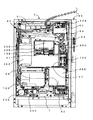
図1には、弾球遊技機の正面図を示す。
【0015】
図示されるように、弾球遊技機1の本体枠(外枠)2の正面には、前面枠(内枠)3が、上部蝶番4Aと下部蝶番4Bにより、開閉可能に取り付けられている。この前面枠3に遊技盤10が取り付けられる。
【0016】
前面枠3の正面には、透明ガラス5Aが装着されたガラス枠5が開閉可能に取り付けられ、遊技盤10正面をガラスで覆うとともに、遊技盤10正面の遊技領域11が透明ガラス5Aを通して透けて見えるようになっている。
【0017】
ガラス枠5には鍵装置5Bが設けられ、通常、前面枠3およびガラス枠5は施錠されている。なお、前面枠3の開放は、図示されない金枠開放センサにより検知される。
【0018】
遊技盤10は前面枠3から取り外し可能で、弾球遊技機本体(弾球遊技機の遊技盤10以外の構成)から分離することができる。これにより、遊技盤10の種類で決まって来る遊技の種類を、変更可能となっている。
【0019】
遊技領域11のほぼ中央には、表示装置(画像表示装置)20が配設されている。この表示装置20は、表示制御装置150(図3参照)に制御されて遊技の進行状態に対応した可変的な画像表示を行うもので、例えば、主たる表示として、遊技状態を表す識別情報である右図柄、中図柄、左図柄の三つの図柄(特別図柄)を液晶画面に表示する。これらの特別図柄としては、例えば、16進法で表現された16個の数字(「0」〜「F」)が表示され、これらの数字からなる帯をスクロールさせながら変動表示することができるようになっている。なお、この表示装置20の表示画面部分は、例えばLCD(液晶表示器)、CRT(ブラウン管)等から構成される。
【0020】
また、この表示装置20の下部には、4つのLEDからなる特別図柄記憶表示器21が備えられている。この特別図柄記憶表示器21は、後述する特別図柄入賞記憶の蓄積数を表示するものである。
【0021】
表示装置20の下方には、内部に大入賞口を備えた特別変動入賞装置12が配設される。この特別変動入賞装置12は、大入賞口ソレノイド12A(図3参照)への通電により開閉される。
【0022】
表示装置20および特別変動入賞装置12の周辺には複数の一般入賞口13が、表示装置20と特別変動入賞装置12の間には始動口14が、それぞれ配設されている。さらに、遊技領域11の最下端には、排出口(アウト口)16が設けられてる。
【0023】
遊技領域11内に打ち込まれた遊技球は、遊技領域11内の各所に配置された風車等の転動誘導部材17により転動方向を変えられながら遊技領域11表面を流下し、大入賞口、一般入賞口13、始動口14のいずれかに入賞するか、または排出口16に入ってアウト球となる。各入賞口(大入賞口、一般入賞口13、始動口14)への入賞は、各入賞装置毎に設けられたセンサにより検出される。詳しくは、一般入賞口13への入賞は各一般入賞口13毎に備えられた一般入賞口センサ51.1〜51.N(図3参照)により、始動口14への入賞は特別図柄始動センサ52(図3参照)により、大入賞口への入賞はカウントセンサ53により、それぞれ検出される。これらの入賞検出に基づいて、入賞した入賞装置の種類に応じた数の賞球が、排出装置(排出ユニット)600(図2参照)から供給皿31に払い出される。
【0024】
なお、大入賞口の内部にはV入賞口が設けられており、大入賞口に入賞した遊技球がさらにこのV入賞口に入賞すると、継続センサ55(図3参照)により検知されるようになっている。
【0025】
始動口14には、普通変動入賞装置(電動ゲート)15が設けられている。この普通変動入賞装置15は、普通変動入賞装置ソレノイド15A(図3参照)への通電により動作し、始動口14の入口の広さを変更するものである。
【0026】
始動口14の左右には、遊技球が通過可能な一対の普通図柄始動ゲート18A、18Bが設けられる。この普通図柄始動ゲート18A、18Bへの遊技球通過は、それぞれに備えられた普通図柄始動センサ53(図3参照)で検知される。
【0027】
特別変動入賞装置12の左右には、それぞれ普通図柄表示器22、普通図柄記憶表示器23が配設される。普通図柄表示器22は、普通図柄(例えば7セグメント表示による数字表示)を表示する表示器である。また、普通図柄記憶表示器23は、4つのLEDからなるもので、後述する普通図柄始動記憶の蓄積数を表示する表示器である。
【0028】
前面枠3の下側には、前面表示パネル(開閉パネル)30が備えられる。この前面表示パネル30には、遊技球の供給皿(上皿)31が備えられる。この供給皿31には、排出装置(排出ユニット)600からの遊技球(賞球または貸球)が、払い出し口31Aを介して払い出される。また、供給皿31の前面には、遊技球を購入するときに操作する球貸ボタン32、プリペイドカードの返却を指令するときに操作するカード返却ボタン33がそれぞれ設けられている。
【0029】
前面表示パネルの下方には、前面操作パネル(固定パネル)35が備えられる。この前面操作パネル35には、受け皿(下皿)36、図示されない打球発射装置の操作部(操作ノブ)501等が配設されている。
【0030】
受け皿36は、操作レバーの操作により、球受け入れ口36Aを介して、供給皿31からの余剰の遊技球を受け入れるものである。さらに、受け皿36内の遊技球は、操作レバー36Bの操作により、下方に排出できるようになっている。この受け皿36が遊技球で満杯になると(オーバーフローすると)、図示されないオーバーフローセンサにより検知される。
【0031】
弾球遊技機1には、サイドランプ71A、71Bや、遊技領域上に配設された複数の装飾LED(図示せず)等の各種発光装置群70(図3参照)が備えられる。また、弾球遊技機1には、音出力装置80(図3参照)が備えられ、遊技状態に対応した効果音出力がなされるようになっている。
【0032】
弾球遊技機1の側部には、カードユニット(球貸機)90が取り付けられている。このカードユニット90の前面にはカード挿入口91が設けられ、このカード挿入口91にプリペイドカードを挿入して、前述の球貸ボタン32を操作することにより、排出装置600から排出された遊技球が、払い出し口31Aから供給皿31に払い出される。
【0033】
図2には、遊技機1ならびにカードユニット90の裏側を示す。
【0034】
遊技盤6の裏面側には、大入賞口、一般入賞口13、始動口14に入賞した入賞球を案内する入賞球集合カバー(図示しない)、表示制御装置150、装飾制御装置200、音制御装置250、遊技盤用外部出力端子41等が取り付けられる。
【0035】
前面枠3の収納フレームの裏面側には、裏機構盤60が取り付けられる。この裏機構盤60の中央部には、遊技盤6の裏面側の各装置(表示制御装置150、装飾制御装置200、音制御装置250等)を点検するための開口窓部65が設けられている。
【0036】
裏機構盤60の上部には、遊技球を貯留する球貯留タンク61、球貯留タンク61の球を樋ユニット部(半端センサユニット)63に導く誘導樋62が取り付けられる。誘導樋62ならびに樋ユニット部63は2条の流路に形成される。樋ユニット部63には、排出ユニット600へ供給されるべき遊技球の不足を検出する半端球検出スイッチ64が備えられる。
【0037】
裏機構盤60の上部右側には、ターミナル基板42が備えられる。このターミナル基板42に設けられた枠用外部出力端子42Aには、管理装置(遊技店において複数の遊技機1を管理するホストコンピュータ)への外部信号線が接続される。また、ターミナル基板42は、外部(遊技店の島設備)からの電源供給線が接続される中継基板である。
【0038】
裏機構盤60の開口窓部65の右側には、樋ユニット部63の球を遊技機前面側の上皿21、下皿23に払い出す排出装置(排出ユニット)600が取り付けられる。
【0039】
裏機構盤60の上部左側には、電源供給装置300が取り付けられる。また、裏機構盤60の下部には、遊技を統括的に制御する遊技制御装置100、排出装置600を制御する排出制御装置400、打球発射装置500を制御する発射制御装置550、カードユニット用中継基板43等が取り付けられる。
【0040】
図3は、遊技機1の制御系を示す構成図である。
【0041】
遊技制御装置100は、遊技の進行を統括的に制御する主制御装置であり、CPU101、ROM102、RAM103、入出力インターフェース104等から構成される。
【0042】
CPU101は、遊技制御装置100による制御(遊技制御)を司るICである。ROM102は、遊技制御のための不変の情報を記憶しているもので、各種プログラムや、遊技制御における大当たりの確率などの定数が記憶されている。
【0043】
RAM103は、CPU101による遊技制御時にワークエリアとして利用されるものである。このRAM103には、停電時にも後述するバックアップ電源302から電源供給され、必要なデータがバックアップされるようになっている。RAM103は、バックアップエリアと制御エリアとから構成される。バックアップエリアは、停電からの復帰時にも原則としてデータ内容が初期化されないエリアで、チェックデータの他、特別図柄乱数カウンタ、特別図柄乱数記憶、普通図柄乱数カウンタ、普通図柄乱数記憶等が、対応する格納領域に記憶されている。一方、制御エリアは、バックアップエリア以外の領域で、タイマ値等が記憶されている。
【0044】
CPU101には、インターフェース104を介して、各種検出装置(一般入賞口センサ51.1〜51.N、特別図柄始動センサ52、普通図柄始動センサ53、カウントセンサ54、継続センサ55)からの検出信号が入力される。遊技制御装置100は、これらの検出信号に基づいて、ROM102に格納されたプログラム(遊技プログラム)により、遊技の統括的な制御(遊技制御)を行う。
【0045】
この遊技制御において、遊技制御装置100は、インターフェース104を介して、各種従属制御装置、すなわち、表示制御装置150(表示装置20における表示を制御する制御装置)、装飾制御装置200(ランプ、LED等の各種発光装置群70を制御する制御装置)、音制御装置250(音出力装置80からの音出力を制御する制御装置)、排出制御装置400(排出装置600を制御する制御装置)に、それぞれ表示制御指令、装飾制御指令、音制御指令、賞球制御指令を送信し、これらの従属制御装置を統括的に制御する。なお、特許請求の範囲における「電気的装置」は、各種従属制御装置によって電気的に制御される装置のことをいい、表示装置20、各種発光装置群70、音出力装置80、排出装置600は、いずれも「電気的装置」に相当する。
【0046】
また、遊技制御装置100は、インターフェース104を介して、特別変動入賞装置12の駆動用ソレノイドである大入賞口ソレノイド12A、普通変動入賞装置15の駆動ソレノイドである普通変動入賞装置ソレノイド15Aに制御信号(ソレノイド制御指令)を送信し、これらのソレノイドへの通電を制御することにより、特別変動入賞装置12、普通変動入賞装置15の開閉動作を制御する。また、インターフェース104を介して、普通図柄表示器22に制御信号を送信し、普通図柄表示器22における可変表示を制御する。さらに、インターフェース104から遊技盤用外部外部出力端子41を介して、管理装置(遊技店において店内の複数の遊技機1を管理するホストコンピュータ)900に、外部出力データを送信する。
【0047】
遊技制御においては、特別図柄に関する大当たりおよび普通図柄に関する当たりの抽選が行われる。
【0048】
まず、特別図柄に関する大当たりの抽選、およびこれに伴う制御について説明する。
【0049】
特別図柄始動センサ52が始動口14への入賞を検知すると、この入賞のタイミング(具体的には、遊技制御装置100に備えられた特別図柄乱数カウンタの入賞検出時点における値)は、特別図柄入賞記憶として、遊技制御装置100のRAM103に備えられた第1〜第4の特別図柄乱数記憶領域に、最大4回分を限度に順次記憶される。この特別図柄乱数記憶領域内に記憶されている特別図柄入賞記憶の数は、特別図柄始動記憶表示器21において、LEDの点灯数で示される。
【0050】
このように記憶された各特別図柄入賞記憶について、特別図柄に関する大当たりの抽選をする。具体的には、特別図柄入賞記憶として記憶されている特別図柄乱数カウンタ値が大当たりである場合、すなわち、始動口14への入賞のタイミングが所定の大当たりのタイミングでなされた場合に「大当たり」と判定され、それ以外の場合は「はずれ」と判定される。
【0051】
大当たり発生の確率(頻度)は、基準時間(例えば600ミリ秒)における大当たり発生のための時間(例えば2ミリ秒)の占める割合として決まる。言い換えれば、特別図柄乱数カウンタの一巡の時間(例えば2×300ミリ秒)における特別図柄乱数カウンタが大当たり値(例えば「7」)をとる時間(例えば2ミリ秒)の割合として決定される。
【0052】
この大当たりの発生確率は、通常の遊技においては所定の確率(例えば1/300)に保たれているが、所定の遊技状態の発生、例えば特定の特別図柄(例えば「777」)による大当たりの発生にともなって変更される。すなわち、遊技は、大当たりの発生確率が通常の確率よりも高い確率(例えば1/50)に保たれる確率変動状態に移行する。なお、この確率変動状態は、引き続く大当たりが確率変動を伴わない大当たり、すなわち特定の特別図柄(例えば「777」)でない特別図柄での大当たりの発生があるまで継続される。
【0053】
特別図柄入賞記憶の存在が確認されると、このような大当たりの抽選とともに、表示装置20の特別図柄が変動(例えばスクロール回転)を始める(変動表示画面の開始)。そして、大当たりが発生したときには、これらの特別図柄が大当たりを示すもので停止し(例えば、三つの図柄が同一の図柄で停止し)、さらに、常態では閉じられていた特別変動入賞装置12が開放状態となり、遊技球が大入賞口に入賞し得る状態、すなわち大当たり状態となる。この大当たり状態は、遊技者にとって通常状態よりも有利な状態である特別遊技状態の一種である。
【0054】
大当たり状態における特別変動入賞装置12の開放は、ラウンド毎に行われる。この各ラウンドは、カウントセンサ55による大入賞口への入賞検出数(カウント数)が所定カウント(例えば10カウント)に達するか、または所定カウントに達しないまま所定時間が経過するまで継続される。そして、この大当たりの各ラウンドでV入賞口への入賞がある限り、その大当たりのラウンドは、所定の上限回数(例えば16ラウンド)まで繰り返される。なお、大当たり状態においては、表示装置20に大当たり画面が表示され、この大当たり画面内においてカウント数やラウンド数が表示される。
【0055】
一方、抽選により大当たりが発生しなかった場合には、表示装置20の表示は、変動表示画面後、大当たりではないことを示す態様で停止し(例えば、三つの図柄が揃わずに停止し)、そのまま通常の(大当たりでない)遊技が続行される。
【0056】
このような大当たり抽選時の図柄停止においては、いわゆるリーチ表示が行われる場合がある。ここで、リーチ表示とは、表示装置20の複数の図柄の総てが変動を停止する前に表示される特殊の表示を言う。具体例としては、例えば、複数の図柄が同一図柄でライン上に揃った状態となる表示(ライン上に揃った状態となる図柄は、停止しているものでもよいし、変動しているものでもよい)、およびこの前段階となる表示等がある。
【0057】
つぎに、遊技制御装置100における普通図柄に関する大当たりの抽選、およびこれに伴う制御について説明する。
【0058】
普通図柄始動ゲート18A、18Bを遊技球が通過すると、この通過は、各ゲート18A、18B毎に設けられた普通図柄始動センサ53で検知される。この遊技球通過のタイミング(具体的には、遊技制御装置100内に備えられた普通図柄乱数カウンタの通過検出時点での値)が、普通図柄入賞記憶として、遊技制御装置100内の所定の記憶領域(普通図柄乱数記憶領域)に、最大で連続した4回分を限度に記憶される。この普通図柄入賞記憶の記憶数は、普通図柄記憶表示器23に、点灯したLEDの数で表示される。
【0059】
このように記憶された各普通図柄入賞記憶について、普通図柄に関する当たりの抽選をする。具体的に、普通図柄入賞記憶として記憶されている普通図柄乱数カウンタ値が当たり値である場合、すなわち、遊技球通過タイミングが所定の当たりのタイミングでなされた場合に「当たり」と判定され、それ以外の場合は「はずれ」と判定される。
【0060】
普通図柄表示装置30に表示される普通図柄は、普通図柄始動センサ53による検知を契機に変動を始める。そして、この普通図柄に関する当たりが発生した場合には、普通図柄が当たり図柄(当たり番号)で停止するとともに、始動口14の手前に設けられた普通変動入賞装置15が所定の時間(例えば0.5秒)だけ大きく開き、遊技球の始動口14への入賞可能性が高められる。
【0061】
普通図柄に関する当たり発生の確率は、通常状態と確率変動状態とで変更される。例えば、通常状態では1/10の確率であったものが、確率変動状態では9/10の高確率に移行する。さらに、普通変動入賞装置15の開放時間についても、例えば、通常状態の0.5秒から確率変動状態の5秒に延長してもよい。これにより、確率変動状態での遊技では、始動口14への入賞が大幅に容易となり、持ち玉をほとんど減らすことなく次回の大当たりを獲得できるようになっている。
【0062】
電源供給装置300は、遊技機1の各種装置に電源供給する装置である。例えば、各種制御装置(遊技制御装置100および各種従属制御装置)には、5V電源が供給される。
【0063】
また、電源供給装置300には、停電検出回路301、バックアップ電源302が備えられる。停電発生時には、停電検出回路301から遊技制御装置100のCPU101に停電発生を知らせる信号が入力されるるとともに、バックアップ電源300から遊技制御装置100のRAM103にバックアップ電源が供給される。
【0064】
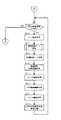
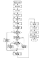
図4、図5には、遊技制御装置100における遊技制御メイン処理の処理手順をフローチャートで示す。
【0065】
電源投入されると、ステップS1において、CPU101の内部が初期化され、ステップS2において、インターフェース104の全出力ポートをOFF状態に設定する。
【0066】
ステップS3では、RAM103内の検査領域のチェックデータが正常であるか否かを判定し、ステップS4.01以下の停電復旧処理に進む。一方、チェックデータが正常でなければステップS5.01以下の処理に進んで、バックアップエリアも含むRAM103の全領域を初期化する(ステップS5.02の完全初期化処理)。
【0067】
ステップS4.01では、RAM103のバックアップエリアにバックアップされていたスタックポインタを、CPU101内部に復帰させる。続くステップS4.02では、停電復旧のための初期化処理を実行する。この初期化処理では、停電発生時にRAM103のバックアップ領域に退避されていたレジスタ類を停電発生前の状態へ復旧させる処理、RAM103制御エリアをクリアする処理等が実行される。
【0068】
ステップS4.03では、バックアップデータに基づいて、インターフェース104の出力ポートにデータを出力して、出力ポートを停電発生直前の状態に復帰させる。なお、この停電復旧時のデータ出力においては、各種従属制御装置への制御指令送信は、あらかじめ定められた所定の順序で実行される。
【0069】
ステップS4.04では、各種従属制御装置に対して、停電復旧処理が終了したことを通知する。なお、排出制御装置400は、ステップS4.03におけるデータ出力により、出力ポートの賞球数データがオフデータからオフデータ以外のデータに変化することにより停電からの復旧を知り得るため、このステップS4.04で重ねて通知する必要はない。
【0070】
ステップS4.05では、割り込みタイマを起動する。後述する通常割り込み処理(図7参照)は、割り込みタイマのタイムアップ毎に実行される。
【0071】
ステップS4.06では、停電発生前は割り込み禁止状態であったか否かを、停電割り込み処理において設定されたフラグを参照して判定し、割り込み禁止状態でなかったならばステップS4.07に進み、割り込み禁止状態であったならばステップS4.09に進む。
【0072】
ステップS4.07では、RAM103のバックアップ領域に退避されていたプログラムカウンタの値などを元のレジスタに復帰させ、続くステップS4.08で割込みを許可して、停電復旧処理ルーチンを終了する。一方、ステップS4.09では、RAM103のバックアップ領域に退避されていたプログラムカウンタの値などを元のレジスタに復帰させ、続くステップS4.10で割込みを禁止して、停電復旧処理ルーチンを終了する。この停電復旧処理ルーチンの終了によって、CPU101は、停電検出時の状態に戻り、停電検出時におけるプログラム上の位置から制御を再開する。
【0073】
一方、ステップS5.01では、通常割込みの受け付けを禁止する。続くステップS5.02の完全初期化処理では、スタックポインタの設定、RAM103の全領域の初期化、RAM103の検査領域へのチェックデータの書込み、各種レジスタ類の初期値設定等を実行する。続いて、ステップS5.03で割り込みタイマを起動し、ステップS5.04で割り込みを許可する。
【0074】
ステップS5.05では、ステップS3と同様に、RAM内の検査領域のチェックデータが正常であるか否かを判定し、正常であればステップS5.06に進み、正常でなければステップS5.01に戻る。このように、チェックデータは、通常処理におけるステップS5.05〜ステップS5.13のループの一巡毎にチェックされ、異常が発見されれば初期化処理がやり直されることになる。
【0075】
ステップS5.06では、エラー監視処理が実行され、各種異常が発生していないかのチェックがなされる。
【0076】
ステップS5.07では、特別図柄ゲーム処理が実行される。この特別図柄ゲーム処理は、遊技制御の中核となる処理であり、特別図柄乱数記憶領域に記憶された特別図柄乱数カウンタ値に基づく大当たりの判定、各種従属制御装置への指令内容の決定等がなされる。特別図柄に関する大当たり状態は特別遊技状態の一種であり、特別図柄乱数カウンタ値に基づく大当たりの判定は、特許請求の範囲における「特別遊技状態の抽選」に相当する。なお、特別図柄ゲーム処理の詳細については、図6とともに後述する。
【0077】
ステップS5.08では、普通図柄ゲーム処理が実行される。この普通図柄ゲーム処理では、特別図柄ゲーム処理と同様に、普通図柄乱数記憶領域に記憶された普通図柄乱数カウンタ値に基づいて、普通図柄に関する当たりの判定がなされる。
【0078】
ステップS5.09では、普通図柄可変制御処理が実行され、普通図柄表示装置22の表示を制御するためのフラグ設定等の処理がなされる。
【0079】
ステップS5.10では、ソレノイド編集処理が実行され、大入賞口ソレノイド12A、普通変動入賞装置ソレノイド15Aに対するソレノイド制御指令が編集される。ステップS5.11では、外部情報編集処理が実行され、管理装置(ホールコンピュータ)900に送信されるべき外部出力データが編集される。
【0080】
ステップS5.12では、コマンド編集処理が実行され、各種従属制御装置への制御指令(表示制御装置150への表示制御指令、装飾制御装置200への装飾制御指令、音制御装置への音制御指令、排出制御装置400への賞球制御指令)が編集される。
【0081】
ステップS5.13では、大当たり初期値乱数が+1更新される。この大当たり初期値乱数は、特別図柄乱数カウンタの周回初期値となるものである(図8参照)。この大当たり初期値乱数更新処理が終了したら、ステップS5.05に戻り、ステップS5.05〜ステップS5.13の処理を繰り返す。
【0082】
なお、停電が発生した場合や遊技機1の電源を切った場合には、停電検出回路301から遊技制御装置100のCPU101に停電を知らせる信号が入力され、遊技制御装置100では、そのときに実行されている処理を中断して、停電割り込み処理が実行される。この停電割り込み処理では、中断された時点のアドレス(プログラムカウンタ)の値を、RAM103に退避させておき、再度電源投入された場合には、この中断された時点のアドレス(プログラムカウンタが示すアドレス)から処理を再開するようになっている(図4のステップS4.01〜ステップS4.10参照)。したがって、遊技制御装置100は、電源供給の停止が挟まった場合でも、電源供給がずっと継続していた場合と同様に、メインルーチンであるステップS5.05〜ステップS5.13の処理を繰り返すことになるので、電源供給の停止や開始のタイミングをあまり考慮することなく、メインルーチンにおける遊技制御のプログラムを作成することができ、プログラム開発が行いやすくなっている。
【0083】
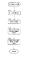
図6には、特別図柄ゲーム処理(図5のステップS5.07の処理)の処理手順をフローチャートで示す。
【0084】
ステップS101では、特図処理タイマがタイムアップしているか否かを判定し、タイムアップしていればステップS102に進み、タイムアップしていなければそのままルーチンを終了する。ここで、特図処理タイマとは、特別図柄に関する各種ゲーム状態の継続時間に対応してタイムアップ時間が設定されるタイマであり、後述の各特図処理番号に対応する処理は、特図処理タイマがタイムアップする毎に実行されることになる。なお、特図処理タイマは、通常割り込み処理中のタイマ更新処理(図7のステップS22)において更新される。
【0085】
ステップS102以降では、特図処理番号にしたがって処理が分岐し、特図処理番号に対応する処理が実行される。ここで、特図処理番号とは、特別図柄に関するゲームがどの進行状態にあるかを示す指標となる数値であって、各状態に対応づけられた「0」〜「6」のいずれかの数値をとるものである。具体的に、特図処理番号=0は特別図柄の変動開始を待機している状態を、特図処理番号=1は特別図柄が変動中の状態を、特図処理番号=2は特別図柄の変動が停止して大当たりの判定を待っている状態を、特図処理番号=3は大当たり動作の開始を報知している状態を、特図処理番号=4は変動入賞装置12が開放している状態を、特図処理番号=5は変動入賞装置12を一時的に閉鎖して次のラウンドの開放に備えている状態を、特図処理番号=6は大当たり動作の終了を報知している状態を、それぞれ示している。
【0086】
ステップS102では、特図処理番号が0であるか否かの判定がなされ、0であればステップS103に進み、0でなければステップS108に進む。
【0087】
ステップS103では、特別図柄始動記憶数が0よりも大きいか否か(特別図柄始動記憶があるか否か)を判定し、0よりも大きければ、ステップS104に進み、0よりも大きくなければ、そのままルーチン終了する。
【0088】
ステップS104の大当たり判定処理では、特別図柄始動記憶数を1減算するとともに、一番古い特別図柄始動記憶が所定の大当たり値(例えば「7」)と一致しているか否かを判定し、一致していれば大当たり判定フラグをセットし、一致しなければ大当たり判定フラグをクリアする。
【0089】
ステップS105の停止図柄決定処理では、ステップS104で設定した大当たり判定フラグに基づいて、左、中、右の3つの特別図柄の停止図柄の組み合わせを決定する。具体的には、大当たり判定フラグがセットされていれぱ、3つの特別図柄が同一図柄となる組み合わせ(例えば「777」のようなゾロ目の組み合わせ)を選択し、セットされていなければ、3つの特別図柄が同一図柄とならない組み合わせ(例えば「248」のようなゾロ目ではない組み合わせ)を選択する。
【0090】
ステップS106では、特図処理番号に「1」を設定するとともに、特図処理タイマには特別図柄の変動に要する時間値(例えば10秒)を設定する。
【0091】
ステップS107のコマンド設定処理では、特図処理番号=1のゲーム状態に対応した演出が行われるように、表示制御装置150への表示制御指令、装飾制御装置200への装飾制御指令、音制御装置250への音制御指令を準備する。
【0092】
ステップS108では、表示制御装置150、装飾制御装置200、音制御装置250の対応する送信準備フラグを総てセットして、ルーチンを終了する。ここで、送信準備フラグとは、制御指令が準備されているにもかかわらず、送信が行われていないことを示すフラグであって、各従属制御装置毎に、対応する送信準備フラグが個別に設けられている。
【0093】
一方、ステップS109では、特図処理番号が1であるか否かの判定がなされ、1であればステップS110に進み、1でなければステップS112に進む。ステップS110では、特図処理番号に2を設定し、特図処理タイマには特別図柄の停止を遊技者に見せるための時間値(例えば0.5秒)を設定する。さらに、特図処理番号=2のゲーム状態に対応した演出が行われるように、表示制御装置150への表示制御指令、装飾制御装置200への装飾制御指令、音制御装置250への音制御指令を準備して、ステップS108に進む。
【0094】
ステップS112では、特図処理番号が2であるか否かの判定がなされ、2であればステップS113に進み、2でなければステップS116に進む。
【0095】
ステップS113では、ステップS104で設定した大当たり判定フラグに基づいて、大当たりが発生したか否かを判定し、大当たりであれば(大当たり判定フラグがセットされていれば)ステップS114に進み、大当たりでなければ(大当たり判定フラグがクリアされていれば)ステップS115に進む。
【0096】
ステップS114では、特図処理番号に3を設定し、特図処理タイマには大当たり発生の報知に要する時間値(例えば10秒)を設定する。さらに、特図処理番号=3のゲーム状態に対応した演出が行われるように、表示制御装置150への表示制御指令、装飾制御装置200への装飾制御指令、音制御装置250への音制御指令を準備して、ステップS108に進む。
【0097】
ステップS115では、特図処理番号に0を設定し、特図処理タイマには0秒を設定してタイムアップした状態にしておく。さらに、特図処理番号=0のゲーム状態に対応した演出が行われるように、表示制御装置150への表示制御指令、装飾制御装置200への装飾制御指令、音制御装置250への音制御指令を準備して、ステップS108に進む。
【0098】
ステップS116では、特図処理番号が6であるか否かの判定がなされ、6であればステップS115に進み、6でなければステップS117に進む。
【0099】
ステップS117では、特図処理番号が3または5であるか否かの判定がなされ、3または5であればステップS118に進み、3でも5でもなければステップS119に進む。
【0100】
ステップS118では、特図処理番号に4を設定し、特図処理タイマには変動入賞装置の開放時間(例えば30秒)を設定する。また、大当たりのラウンド数も+1更新する。さらに、特図処理番号=4のゲーム状態に対応した演出が行われるように、表示制御装置150への表示制御指令、装飾制御装置200への装飾制御指令、音制御装置250への音制御指令を準備して、ステップS108に進む。
【0101】
ステップS119では、大当たり状態を終了すべき場合と継続すべき場合とで処理が異なる。大当たり状態を終了すべき場合(変動入賞装置12の開放中にV入賞口への入賞がなかった場合、または大当たりのラウンド数が予め定められた最大値(例えば16)となった場合)には、特図処理番号に6を設定し、特図処理タイマには大当たり終了の報知に要する時間値(例えば20秒)を設定する。また、特図処理番号=6のゲーム状態に対応した演出が行われるように、表示制御装置150への表示制御指令、装飾制御装置200への装飾制御指令、音制御装置250への音制御指令を準備して、ステップS108に進む。一方、大当たり状態を継続すべき場合(上記大当たり状態を終了すべき場合以外の場合)には、特図処理番号に5を設定し、特図処理タイマには大当たりが継続することを示す報知に要する時間値(例えば2秒)を設定する。さらに、特図処理番号=5のゲーム状態に対応した演出が行われるように、表示制御装置150への表示制御指令、装飾制御装置200への装飾制御指令、音制御装置250への音制御指令を準備して、ステップS108に進む。
【0102】
図7には、遊技制御装置100における通常割り込み処理の処理手順をフローチャートで示す。この通常割り込み処理は、上記遊技制御メイン処理(図4)に対する割り込み処理として、所定のタイマ割り込み時間毎(例えば2ms毎)に実行されるものである。
【0103】
ステップS11では、強制割り込み(停電割り込み)以外の、各種割り込み処理を禁止する。ステップS12では、CPU101のレジスタ値を、RAM103のスタックエリアに退避させる(保存する)。
【0104】
ステップS13では、ウォッチドッグタイマをリセットする。ここで、ウォッチドッグタイマは、CPU101の暴走を監視するためのタイマで、所定時間以内にリセットされないと、警報信号を発するものである。つまり、CPU101が暴走して通常割り込み処理が実行されなくなってしまった場合には、このステップS13のリセットがなされないので、警報信号が発せられ、異常を検知することができる。
【0105】
ステップS14では、センサ読み込み処理が実行され、各種検出装置(一般入賞口センサ51.1〜51.N、特別図柄始動センサ52、普通図柄始動センサ53、カウントセンサ54、継続センサ55)による検出信号が、検出装置毎に区別されて、読み込まれる(詳しい処理手順は、図8のフローチャート参照)。なお、このステップS14のセンサ読み込み処理より前に行われる処理(ステップS11の割り込み禁止処理、ステップS12のレジスタ退避処理、ステップS13のウォッチドッグタイマをリセットする処理)は、いずれも一定の時間で実行される定型的な処理であるので、総ての通常割り込み処理において、割り込みルーチンの開始から一定時間経過したところで実行されることになる。
【0106】
ステップS15では、出力処理が実行され、遊技制御メイン処理(図5)のステップS5.10で編集されたソレノイド制御指令、ステップS5.11で編集された外部出力データを、出力ポートに設定する。出力ポートに設定されたデータにしたがって、対応する装置が駆動または停止する。
【0107】
ステップS16では、表示制御指令送信処理が実行され、表示制御装置150に対応する送信準備フラグがセットされていれば、遊技制御メイン処理(図4)のステップS5.12で準備された表示制御指令を、出力ポートに設定し、その後、表示制御装置150に対応する送信準備フラグをクリアする。出力ポートに設定された表示制御指令は、表示制御装置150に送信される。したがって、表示制御指令を送信可能なタイミングは、通常割り込み処理毎に発生することになる。
【0108】
ステップS16に続いては、ステップS17の排出制御指令送信処理、ステップS18の音制御指令送信処理、ステップS19の装飾制御指令送信処理のいずれか一つが、時分割で選択され、実行される。つまり、3回の通常割り込み処理を1つのサイクルとして、1回目の通常割り込み処理ではステップS17の排出制御指令送信処理が、2回目の通常割り込み処理ではステップS18の音制御指令送信処理が、3回目の通常割り込み処理ではステップS19の装飾制御指令送信処理が、それぞれ実行され、このサイクルが繰り返されるようになっている。
【0109】
これら排出制御指令送信処理、音制御指令送信処理、装飾制御指令送信処理では、それぞれ排出制御装置400、音制御装置250、装飾制御装置200に対応する送信準備フラグがセットされている場合にのみ、それぞれ排出制御指令、音制御指令、装飾制御指令を出力ポートに設定し、その後、対応する送信準備フラグをクリアする。出力ポートに設定された各制御指令は、それぞれ排出制御装置400、音制御装置250、装飾制御装置200に送信される。なお、排出制御指令は、後述するステップS21のセンサ入力判定処理で、また音制御指令と装飾制御指令は、遊技制御メイン処理のステップS5.12で準備されたものである。
【0110】
このように、排出制御指令、音制御指令、装飾制御指令は、表示制御指令と異なり、編集された指令を直ちに送信することまでは要求されていないので、時分割処理により送信され、3回の通常割り込み処理毎に順番に送信可能なタイミングを得ることになる。
【0111】
なお、対応する送信準備フラグがセットされていない場合には、その制御指令の送信処理をとばして、次の順番の送信処理を実行するようにしてもよい。これによれば、例えば、本来なら排出制御指令送信処理を実行すべき場合であっても、排出制御装置400に対応する送信準備フラグがクリアされており、音制御装置250に対する送信準備フラグがセットされているときには、本来ならば次の順番の音制御指令送信処理を実行することになる。
【0112】
ステップS20では、遊技用乱数更新処理が実行され、特別図柄乱数カウンタおよび普通図柄乱数カウンタが更新される(詳しい処理手順は、図10のフローチャート参照)。
【0113】
ステップS21では、センサ入力判定処理が実行され、ステップS14で読み込まれた各種検出装置の信号状態を判定し、遊技球検出の有無を判定する(詳しい処理手順は、図11のフローチャート参照)。この判定も、検出装置毎に区別して実行される。また、検出に対応して賞球排出を行うべき検出装置、すなわち各種入賞口(大入賞口、一般入賞口13、始動口14)に備えられたセンサ(カウントセンサ53、一般入賞口センサ51.1〜51.N、特別図柄始動センサ52)による検出があった場合には、その検出装置(入賞口)の種類に応じて決まる賞球数の排出を指示する排出制御指令を準備し、排出制御装置400に対応する送信準備フラグをセットする。
【0114】
ステップS22では、タイマ更新処理が実行され、遊技制御メイン処理(図4、図5)の各処理で使用されるタイマを更新する。なお、特図処理タイマは、このタイマ更新処理で減算更新されるが、既にタイムアップしている場合(特図処理タイマ=0秒の場合)には、そのタイマ値は0秒に保持されることになる。
【0115】
ステップS23では、スタック領域に退避しておいたレジスタの値を、元のレジスタに戻す。ステップS24では、ステップS11で禁止した割込みを許可して、ルーチンを終了する。
【0116】
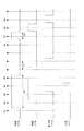
図8は、センサ読み込み処理(図7のステップS14の処理)の処理手順を示すフローチャートである。また、図9は、このセンサ読み込み処理における入力エッジの設定を説明するためのタイミングチャートである。
【0117】
ステップS31では、各検出装置から遊技制御装置100のインターフェース104のポートに入力された信号レベルが、遊技制御装置100のCPU101に取り込まれる。この取り込みは、各検出装置毎に行われる。図9では、R1、R2、…等が、この取り込みタイミングである。センサ読み込み処理は通常割り込み処理毎に実行されるので、これらの取り込みR1、R2、…は、タイマ割り込み時間Ti毎に実行されることになる。
【0118】
ステップS32では、入力エッジの設定処理が実行される。具体的には、各検出装置について、ステップS31で取り込まれた入力レベル(今回レベル)と、前回と前々回のセンサ読み込み処理で読み込まれてそれぞれ保存されていた入力レベル(前回レベル、前々回レベル)に基づき、今回レベルと前回レベルがハイレベル(検出あり)、前々回レベルがローレベル(検出無し)のときに、その検出装置により遊技球検出があったと判断する。遊技球検出があったと判定されると、その検出装置についての入力エッジがハイレベルとされる。
【0119】
ステップS33では、前回入力レベル領域に保存されていた前回の入力レベルを、前々回入力レベル領域に保存する。ステップS34では、今回の入力レベルを、前回レベル領域に保存して、ルーチンを終了する。
【0120】
つぎに、図9にしたがって、入力エッジの設定処理(ステップS32)について、詳しく説明する。図9の左側に示すように、ポート入力のレベル取り込みは、R1、R2、R3、R4のタイミングでなされる。検出装置による検出があり、入力レベルが取り込みタイミングR1とR2の間で立ち上がると、今回レベルは、R1ではローレベル、R2ではハイレベルとなる。この場合、前回レベル、前々回レベルは、いずれもローレベルである。
【0121】
検出装置による検出に基づく場合、ポート入力のハイレベルは、1パルス間に2回以上のレベル取り込みがなされるパルス幅Wsを持つ。したがって、取り込みタイミングR2に続くR3では、今回レベルと前回レベルがハイレベル、前々回レベルがローレベルとなる。これにより、入力エッジがハイレベルに設定される。この入力エッジのハイレベルが、タイミングR4に対応する通常割り込み処理において検出されて、検出装置による検出ありとの判定がなされることになる。なお、入力エッジは、次の通常割り込み処理のタイミングR5の前に立ち下がって、2重に検出されることはないようになっている。
【0122】
一方、図9の右側には、入力レベルの立ち上がりがノイズによる場合を示す。このようなノイズの場合には、パルス幅Wnがレベル取り込みの時間間隔Tiよりも短いので、入力エッジが設定されることはない。つまり、取り込みタイミングR6とR7の間でノイズによる立ち上がりがあっても、このハイレベルは、次の取り込みタイミングR8までに立ち下がってしまう。このため、今回レベルと前回レベルがハイレベル、前々回レベルがローレベルとなることはなく、入力エッジの設定がなされることはない。
【0123】
このようにして、いずれかの検出装置による検出があった場合には、その検出装置について入力エッジが立てられる一方で、ノイズ等により入力レベルが攪乱されたに過ぎない場合には、入力エッジが立つことがないようになっている。
【0124】
図10には、遊技用乱数更新処理(図7のステップS20の処理)の処理手順をフローチャートで示す。
【0125】
ステップS41では、特別図柄乱数カウンタを+1更新する。続くステップS42では、更新の結果、特別図柄乱数カウンタが上限値(例えば300)以上となったか否かの判定がなされ、上限値以上であれば、ステップS43で特別図柄乱数カウンタに下限値(例えば0)を設定してからステップS44に進み、上限値以上でなければ、そのままステップS44に進む。このように、特別図柄乱数カウンタは、下限値〜上限値−1(例えば0〜299)の間で、循環して更新される。
【0126】
ステップS44では、特別図柄乱数カウンタの値が周回初期値であるか否かの判定がなされ、周回初期値であればステップS45に進み、周回初期値でなければステップS47に進む。
【0127】
ステップS45では、大当たり初期値乱数(図5のステップS5,13参照)を周回初期値に設定する。続くステップS46では、ステップS45で設定された周回初期値を、特別図柄乱数カウンタに設定して、ステップS47に進む。このように、特別図柄乱数カウンタ値は、周回初期値からスタートして、一巡して周回初期値に戻ってくるまでカウントされるとともに、周回初期値に戻ってきたならば、大当たり初期値乱数に基づいて新たに設定された周回初期値から、新たなカウントが開始されることになる。
【0128】
ステップS47では、普通図柄乱数カウンタの更新処理が実行される。この更新処理では、普通図柄乱数カウンタは、所定の範囲で巡回して+1ずつ更新される。ステップS48では、演出用乱数の更新処理が実行され、ルーチンを終了する。なお、演出用乱数は、各種演出(各種発光装置群70の発光動作、音出力装置からの音声出力等)の内容を決定するために使用される乱数である。
【0129】
図11には、センサ入力判定処理(図7のステップS21の処理)の処理手順をフローチャートで示す。
【0130】
ステップS51では、特別図柄始動センサ52の入力エッジが有りか無しか(ハイレベルかローレベルか)の判定がなされ、入力エッジ有り(特別図柄始動センサ52による検出有り)ならばステップS52に進み、入力エッジ無し(特別図柄始動センサ52による検出無し)ならばステップS55に進む。
【0131】
ステップS52では、特別図柄始動記憶数が4より小さいか否かの判定がなされ、4より小さければステップS53に進み、4より小さくなければステップS55に進む。
【0132】
ステップS53では、特別図柄始動記憶数を+1更新する。続くステップS54では、その時点での特別図柄乱数カウンタ値を、特別図柄始動記憶として記憶し、ステップS55に進む。このように、特別図柄始動記憶は、4個までを限度に記憶され、特別図柄始動記憶数が4であるときに入力エッジの検出があっても、新たに記憶されることはない。
【0133】
ステップS55では、ステップS55では、普通図柄始動センサ53の入力判定処理が実行される。さらに、ステップS56では、他の各種検出装置(一般入賞口センサ51.1〜51.N、カウントセンサ54、継続センサ55)の入力判定処理が実行される。これらの入力判定処理では、上述した特別図柄始動センサ52の場合と同様に、それぞれの検出装置の入力エッジが立ち上がっているか否かが判定され、立ち上がっていれば検出有りと判定する。ステップS56の入力判定処理が終了したら、ルーチンを終了する。
【0134】
図12には、本発明の他の実施の形態における通常割り込み処理の処理手順を示す。
【0135】
この実施の形態では、表示制御指令、音制御指令、装飾制御指令、排出制御指令の各制御指令について、送信の優先順位が設けられている点で、上記実施の形態と異なり、他の点では共通する。
【0136】
図12の通常割り込み処理では、ステップS61〜ステップS66の各処理において、それぞれ、上記図7の通常割り込み処理におけるステップS11〜ステップS16と同様の処理を実行する。したがって、ステップS66の表示制御指令送信処理は、総ての通常割り込み処理で必ず実行されることになる。すなわち、表示装置20における表示は、遊技の進行に対して特に正確なタイミングで対応する必要があるので、表示制御指令は総ての通常割り込み処理において送信可能となっている。
【0137】
ステップS67〜ステップS72の処理は、本実施の形態の特徴となる部分で、制御指令には、音制御指令、装飾制御指令、排出制御指令の順で優先順位がつけられている。
【0138】
ステップS67では、音制御指令送信の準備状態であるか否か(音制御装置250に対する送信準備フラグがセットされているか否か)の判定がなされ、準備状態であれば、ステップS68で音制御指令送信処理(図7のステップS18と同様の処理)を実行して、ステップS73に進む。一方、音制御指令送信の準備状態でなければ、ステップS69に進む。
【0139】
ステップS69では、装飾制御指令送信の準備状態であるか否か(装飾制御装置200に対する送信準備フラグがセットされているか否か)の判定がなされ、準備状態であれば、ステップS70で装飾制御指令送信処理(図7のステップS19と同様の処理)を実行して、ステップS73に進む。一方、装飾制御指令送信の準備状態でなければ、ステップS71に進む。
【0140】
ステップS69では、排出制御指令送信の準備状態であるか否か(排出制御装置400に対する送信準備フラグがセットされているか否か)の判定がなされ、準備状態であれば、ステップS70で排出制御指令送信処理(図7のステップS17と同様の処理)を実行して、ステップS73に進む。一方、装飾制御指令送信の準備状態でなければ、ステップS73に進む。
【0141】
このように、音制御指令、装飾制御指令、排出制御指令には、この順で優先順位が付けられ、優先順位が上位の制御指令が送信の準備状態にあるときには、その制御指令のみが送信され、下位の制御指令送信は次回以降の通常割り込み処理に回される。これにより、各制御指令は、ゲームの進行上、正確な送信タイミングが要求される順に、優先的に送信されることになり、結果として、各種従属制御装置による各種装置の制御を、遊技者に違和感を抱かせないように実行できる。
【0142】
ステップS73〜ステップS77の各処理においては、それぞれ、上記図7のステップS20〜ステップS24と同様の処理が実行されて、ルーチンを終了する。
【0143】
以上のように、本発明によれば、遊技制御装置100から従属制御装置(表示制御装置100、装飾制御装置200、音制御装置250、排出制御装置400)への制御指令送信処理は、通信割り込み処理(図7、図12)において実行されるが、各通信割り込み処理においては、複数の従属制御装置のうちから選択された一部の従属制御装置に対してのみ、制御指令送信処理が行われる。したがって、複数の制御装置について送信準備状態が同時に発生したとしても、各通信割り込み処理における制御指令送信のための処理時間を短縮することができるので、その分、他の処理に割り当てられる時間を長くでき、遊技制御装置100における各種処理を滞りなく実行できる。
【0144】
また、表示制御装置150に対して表示制御指令を送信する処理(図7のステップS16、図12のステップS66)は、総ての通信割り込み処理において実行されるようになっている。したがって、表示制御指令は、送信の必要が生じた場合に、タイミングが遅れることなく送信されるので、表示装置20においては、ゲームの進行に正しく同期した表示がなされる。
【0145】
また、図7の通信割り込み処理では、装飾制御装置200、音制御装置250、排出制御装置400への制御指令送信処理が、順番に実行されるので、これらの各従属制御装置に対する送信処理は均等になされる。すなわち、各従属制御装置に対する制御指令の送信は、偏りなくバランスして実行される。したがって、各従属制御装置による遊技の演出等の制御は、バランスよく実行される。
【0146】
また、図12の通信割り込み処理では、各種従属制御装置には優先順位が付けられて、この優先順位に基づいて制御指令の送信処理が実行される従属制御装置が選択される。具体的には、表示制御装置150は、総ての通信割り込み処理で送信処理が実行されるとともに、残りの従属制御装置については、音制御装置250、装飾制御装置200、排出制御装置400の順で優先して制御指令の送信処理が行われる。これにより、制御が遊技の進行に対して遅れることなく同期して行われる必要性が高いものほど、優先的に制御指令が送信されることになり、結果として、遊技の各種演出等を、遊技者に不都合や違和感を与えることなく実行できる。
【0147】
なお、今回開示された実施の形態は総ての点で例示であって制限的なものではない。また、本発明の範囲は、特許請求の範囲によって示されるもので、特許請求の範囲内での総ての変更を含むものである。
【図面の簡単な説明】
【図1】本発明の実施の形態における遊技機を示す正面図である。
【図2】同じく遊技機を示す裏面図である。
【図3】同じく制御系を示す構成図である。
【図4】同じく遊技制御メイン処理の処理手順を示すフローチャートである。
【図5】同じく遊技制御メイン処理の処理手順を示すフローチャートである。
【図6】同じく特別図柄ゲーム処理の処理手順を示すフローチャートである。
【図7】同じく通常割り込み処理の処理手順を示すフローチャートである。
【図8】同じくセンサ読み込み処理の処理手順を示すフローチャートである。
【図9】同じくセンサ読み込み処理における入力エッジの設定を説明するためのタイミングチャートである。
【図10】同じく遊技用乱数更新処理の処理手順を示すフローチャートである。
【図11】同じくセンサ入力判定処理の処理手順を示すフローチャートである。
【図12】本発明の他の実施の形態における通常割り込み処理の処理手順を示すフローチャートである。
【符号の説明】
100 遊技制御装置
150 表示制御装置
200 装飾制御装置
250 音制御装置
400 排出制御装置[0001]
BACKGROUND OF THE INVENTION
The present invention relates to a gaming machine that performs control command transmission from a game control device to a plurality of subordinate control devices, and performs overall control of the game with the game control device.
[0002]
[Prior art]
Some gaming machines control the game in an integrated manner by the game control device by transmitting control commands from the game control device (main control device) to a plurality of subordinate control devices. For example, in a pachinko machine, a control command is transmitted from a game control device to a subordinate control device such as a display control device, a decoration control device, a sound control device, or a discharge control device, and these subordinate control devices receive control commands from the game control device. The display device, various light emitting devices (lamps, etc.), sound output device, and discharge device are controlled based on the above.
[0003]
[Problems to be solved by the invention]
By the way, the necessity for transmission of such a control command occurs according to the progress of the game, and there is no particular regularity, so there is a case where the control command is transmitted to a plurality of subordinate control devices all at once. There is. However, in the game control device, in addition to the control command transmission to the subordinate control device, it is necessary to perform various processes such as a lottery for the special game state (big win), so the processing time for transmitting the control command to the subordinate control device is long. It is not preferable that it becomes long. Specifically, the transmission of the control command from the game control device to the subordinate control device is executed in an interrupt routine for the main routine of control in the game control device, but the processing time of this interrupt routine is increased. This is not preferable because the processing time is reduced.
[0004]
The present invention was made paying attention to such problems, in a gaming machine that performs control command transmission from a game control device to a plurality of subordinate control devices, and performs overall control of the game with the game control device,Reduce processing load without reducing main routine processing timeThe purpose is to provide what can be done.
[0005]
[Means for Solving the Problems]
In the first invention,A special game state that is advantageous to the player when a special symbol game in which a plurality of special symbols are variably displayed on a display device based on a winning at the start opening and the result of the special symbol game is in a predetermined symbol combination mode In a gaming machine that can generate a game, a CPU that controls game control, a ROM that stores a game control program, a RAM that is supplied with backup power and can store various data even when a power failure occurs, and the CPU and various devices A game control device having an input / output interface for inputting / outputting signals between the main routine, the game control device including a main routine repeated as a loop process after performing an initialization process, An interrupt routine executed every time the interrupt timer expires, and in the main routine, A big hit initial value random number update process for updating the big hit initial value random number is executed, and in the interrupt routine, a special symbol random number counter for determining whether or not to generate the special gaming state is stored in the RAM A special symbol random number counter update process that circulates and updates within a range, and a cycle that sets the value of the big hit initial value random number as a new cycle initial value when the special symbol random number counter makes a round and returns to the cycle initial value Initial value setting processing is executed, and in the initialization processing, output port OFF setting processing for setting all output ports of the input / output interface to an OFF state, and whether data in the RAM are normal are determined. A data determination process, and when the data determination process determines that the data is normal, the control of the game control device While performing a power failure recovery process that restores the state to the state at the time of the power failure occurrence and an interrupt timer activation process that activates the interrupt timer, when it is determined in the data determination process that the data is not normal, A complete initialization process for initializing all areas of the RAM and an interrupt timer starting process for starting the interrupt timer are executed..
[0006]
In the second invention,Various decoration devices for decorating a gaming machine and a sound output device are provided, and in the interrupt routine, an effect random number stored in the RAM and determining the effect contents of the various decoration devices and the sound output device is updated. Execute the random number update process for production.
[0009]
Operation and effect of the invention
FirstAnd secondIn the invention ofA special game state that is advantageous to the player when a special symbol game in which a plurality of special symbols are variably displayed on a display device based on a winning at the start opening and the result of the special symbol game is in a predetermined symbol combination mode In a gaming machine that can generate a game, a CPU that controls game control, a ROM that stores a game control program, a RAM that is supplied with backup power and can store various data even when a power failure occurs, and the CPU and various devices A game control device having an input / output interface for inputting / outputting signals between the main routine, the game control device including a main routine repeated as a loop process after performing an initialization process, An interrupt routine executed every time the interrupt timer expires, and in the main routine, A big hit initial value random number update process for updating the big hit initial value random number is executed, and in the interrupt routine, a special symbol random number counter for determining whether or not to generate the special gaming state is stored in the RAM A special symbol random number counter update process that circulates and updates within a range, and a cycle that sets the value of the big hit initial value random number as a new cycle initial value when the special symbol random number counter makes a round and returns to the cycle initial value Initial value setting processing is executed, and in the initialization processing, output port OFF setting processing for setting all output ports of the input / output interface to an OFF state, and whether data in the RAM are normal are determined. A data determination process, and when the data determination process determines that the data is normal, the control of the game control device While performing a power failure recovery process that restores the state to the state at the time of the power failure occurrence and an interrupt timer activation process that activates the interrupt timer, when it is determined in the data determination process that the data is not normal, Since the complete initialization process for initializing the entire area of the RAM and the interrupt timer starting process for starting the interrupt timer are executed, the processing load on the game control device of the main routine is reduced. Therefore, the processing time of the main routine and the interrupt routine can be processed without redundancy.
[0010]
Also, if a power failure occurs or the gaming machine is turned off, when the power is turned on again, initialization processing is performed before execution of the main routine, and processing is resumed from the point of interruption. The Therefore, the game control device repeats the main routine process even when the power supply is stopped, just like when the power supply has continued, so the timing for stopping and starting the power supply can be set. Without much consideration, it is possible to create a game control program in the main routine, and it is easy to develop the program.
[0013]
DETAILED DESCRIPTION OF THE INVENTION
Hereinafter, embodiments of the present invention will be described with reference to the accompanying drawings.
[0014]
FIG. 1 shows a front view of a ball game machine.
[0015]
As shown in the drawing, a front frame (inner frame) 3 is attached to the front surface of the main body frame (outer frame) 2 of the
[0016]
A
[0017]
The
[0018]
The
[0019]
A display device (image display device) 20 is disposed almost at the center of the
[0020]
In addition, a special
[0021]
Below the
[0022]
In the vicinity of the
[0023]
The game balls that have been driven into the
[0024]
In addition, a V winning opening is provided inside the big winning opening, and when a game ball that has won the big winning opening further wins the V winning opening, it is detected by the continuation sensor 55 (see FIG. 3). It has become.
[0025]
The starting
[0026]
A pair of normal
[0027]
A
[0028]
A front display panel (open / close panel) 30 is provided below the
[0029]
A front operation panel (fixed panel) 35 is provided below the front display panel. The front operation panel 35 is provided with a receiving tray (lower plate) 36, a not-shown operation unit (operation knob) 501 of a ball striking device.
[0030]
The
[0031]
The bullet
[0032]
A card unit (ball lending machine) 90 is attached to the side of the
[0033]
FIG. 2 shows the
[0034]
On the back side of the
[0035]
A back mechanism panel 60 is attached to the back side of the storage frame of the
[0036]
A ball storage tank 61 for storing game balls and a guide rod 62 for guiding the balls of the ball storage tank 61 to the basket unit portion (half-end sensor unit) 63 are attached to the upper part of the back mechanism board 60. The guide rod 62 and the rod unit 63 are formed in two channels. The heel unit 63 is provided with a half-end
[0037]
A
[0038]
On the right side of the opening window 65 of the back mechanism board 60, a discharge device (discharge unit) 600 that pays out the balls of the basket unit 63 to the
[0039]
A
[0040]
FIG. 3 is a configuration diagram showing a control system of the
[0041]
The
[0042]
The
[0043]
The
[0044]
The
[0045]
In this game control, the
[0046]
In addition, the
[0047]
In the game control, a lottery for a special jackpot and a special jackpot is performed.
[0048]
First, the jackpot lottery with respect to the special symbol and the control accompanying this will be described.
[0049]
When the special symbol start sensor 52 detects a winning at the
[0050]
For each special symbol winning memory stored in this way, a jackpot lottery regarding the special symbol is made. Specifically, when the special symbol random number counter value stored as the special symbol winning memory is a big win, that is, when the timing of winning a prize to the
[0051]
The probability (frequency) of jackpot occurrence is determined as a ratio of time for jackpot occurrence (for example, 2 milliseconds) in a reference time (for example, 600 milliseconds). In other words, it is determined as a ratio of the time (for example, 2 milliseconds) at which the special symbol random number counter takes a big hit value (for example, “7”) in one round of the special symbol random number counter (for example, 2 × 300 milliseconds).
[0052]
The probability of the jackpot is maintained at a predetermined probability (for example, 1/300) in a normal game, but the occurrence of a predetermined gaming state, for example, the occurrence of a jackpot due to a specific special symbol (for example, “777”). Changed with That is, the game shifts to a probability fluctuation state in which the jackpot occurrence probability is maintained at a higher probability (for example, 1/50) than the normal probability. This probability variation state is continued until the subsequent jackpot is a jackpot that does not involve a probability variation, that is, a jackpot with a special symbol that is not a specific special symbol (for example, “777”).
[0053]
When the presence of the special symbol winning memory is confirmed, the special symbol of the
[0054]
The special variable winning
[0055]
On the other hand, when no big win has occurred due to the lottery, the display of the
[0056]
In such a symbol stop at the time of jackpot lottery, so-called reach display may be performed. Here, the reach display refers to a special display that is displayed before all of the plurality of symbols of the
[0057]
Next, the jackpot lottery regarding the normal symbol in the
[0058]
When the game ball passes through the normal
[0059]
For each ordinary symbol winning memory stored in this manner, a winning lottery regarding the ordinary symbols is performed. Specifically, when the normal symbol random number counter value stored as the normal symbol winning memory is a winning value, that is, when the game ball passing timing is made at a predetermined winning timing, it is determined as “winning”, and Otherwise, it is determined as “out of”.
[0060]
The normal symbol displayed on the normal
[0061]
The probability of occurrence of hits for normal symbols is changed between the normal state and the probability variation state. For example, a probability of 1/10 in the normal state shifts to a high probability of 9/10 in the probability fluctuation state. Further, the opening time of the normal
[0062]
The
[0063]
In addition, the
[0064]
4 and 5 are flowcharts showing the processing procedure of the game control main process in the
[0065]
When the power is turned on, the inside of the
[0066]
In step S3, it is determined whether or not the check data in the inspection area in the
[0067]
In step S4.01, the stack pointer backed up in the backup area of the
[0068]
In step S4.03, data is output to the output port of the
[0069]
In step S4.04, various subordinate control devices are notified that the power failure recovery processing has been completed. Since the
[0070]
In step S4.05, an interrupt timer is started. Normal interrupt processing (see FIG. 7), which will be described later, is executed every time the interrupt timer expires.
[0071]
In step S4.06, it is determined with reference to the flag set in the power failure interrupt processing whether or not the interrupt was disabled before the power failure occurred. If the interrupt was not disabled, the process proceeds to step S4.07. If so, the process proceeds to step S4.09.
[0072]
In step S4.07, the value of the program counter saved in the backup area of the
[0073]
On the other hand, in step S5.01, acceptance of normal interrupts is prohibited. In the subsequent complete initialization process in step S5.02, the stack pointer is set, the entire area of the
[0074]
In step S5.05, similarly to step S3, it is determined whether or not the check data in the inspection area in the RAM is normal. If normal, the process proceeds to step S5.06. If not normal, step S5.01 is determined. Return to. In this way, the check data is checked for each round of the loop from step S5.05 to step S5.13 in the normal process, and if an abnormality is found, the initialization process is repeated.
[0075]
In step S5.06, an error monitoring process is executed to check whether various abnormalities have occurred.
[0076]
In step S5.07, a special symbol game process is executed. This special symbol game process is a core process of game control, and a jackpot determination based on a special symbol random number counter value stored in the special symbol random number storage area, determination of command contents to various subordinate control devices, and the like are made. The The jackpot state related to the special symbol is a kind of special gaming state, and the determination of the jackpot based on the special symbol random number counter value corresponds to “lottery of special gaming state” in the claims. Details of the special symbol game process will be described later with reference to FIG.
[0077]
In step S5.08, a normal symbol game process is executed. In the normal symbol game process, as in the special symbol game process, the winning determination regarding the normal symbol is made based on the normal symbol random number counter value stored in the normal symbol random number storage area.
[0078]
In step S5.09, normal symbol variable control processing is executed, and processing such as flag setting for controlling the display of the normal
[0079]
In step S5.10, solenoid editing processing is executed, and solenoid control commands for the big prize opening solenoid 12A and the normal variation prize winning
[0080]
In step S5.12, command editing processing is executed, and control commands to various subordinate control devices (display control commands to display
[0081]
In step S5.13, the big hit initial value random number is updated by +1. This jackpot initial value random number serves as the cyclic initial value of the special symbol random number counter (see FIG. 8). When the jackpot initial value random number update process is completed, the process returns to step S5.05, and the processes of steps S5.05 to S5.13 are repeated.
[0082]
When a power failure occurs or when the
[0083]
FIG. 6 is a flowchart showing the procedure of the special symbol game process (the process of step S5.07 in FIG. 5).
[0084]
In step S101, it is determined whether or not the special figure processing timer is up. If the time is up, the process proceeds to step S102. If the time is not up, the routine is ended as it is. Here, the special figure processing timer is a timer in which a time-up time is set corresponding to the duration of various game states related to special symbols, and the processing corresponding to each special figure processing number described later is a special figure processing. It will be executed every time the timer expires. The special figure processing timer is updated in the timer update process (step S22 in FIG. 7) during the normal interrupt process.
[0085]
After step S102, the process branches according to the special figure process number, and the process corresponding to the special figure process number is executed. Here, the special figure process number is a numerical value that is an index indicating in which progress the game related to the special symbol is in, and is a numerical value of any one of “0” to “6” associated with each state. It is to take. Specifically, the special symbol process number = 0 indicates a state waiting for the start of special symbol change, the special symbol process number = 1 indicates that the special symbol is changing, and the special symbol process number = 2 indicates a special symbol. The state where the fluctuation is stopped and waiting for the jackpot determination, the special figure process number = 3 is informing the start of the big hit operation, and the special figure process number = 4 is opened by the variable winning
[0086]
In step S102, it is determined whether or not the special figure process number is 0. If it is 0, the process proceeds to step S103, and if it is not 0, the process proceeds to step S108.
[0087]
In step S103, it is determined whether or not the number of special symbol starting memories is greater than 0 (whether or not there is a special symbol starting memory). If greater than 0, the process proceeds to step S104, and if not greater than 0, The routine ends as it is.
[0088]
In the jackpot determination process in step S104, the special symbol starting memory number is decremented by 1, and it is determined whether or not the oldest special symbol starting memory matches a predetermined jackpot value (for example, “7”). If it matches, the jackpot determination flag is set. If they do not match, the jackpot determination flag is cleared.
[0089]
In the stop symbol determination process of step S105, combinations of stop symbols of three special symbols of left, middle, and right are determined based on the jackpot determination flag set in step S104. Specifically, if the jackpot determination flag is set, select a combination in which the three special symbols are the same symbol (for example, a combination of double eyes such as “777”). A combination in which the special symbol is not the same symbol (for example, a combination that is not a doublet such as “248”) is selected.
[0090]
In step S106, “1” is set as the special figure processing number, and a time value (for example, 10 seconds) required for the special symbol fluctuation is set in the special figure processing timer.
[0091]
In the command setting process of step S107, a display control command to the
[0092]
In step S108, all the corresponding transmission preparation flags of the
[0093]
On the other hand, in step S109, it is determined whether or not the special figure process number is 1. If 1, the process proceeds to step S110, and if not, the process proceeds to step S112. In step S110, 2 is set in the special figure processing number, and a time value (for example, 0.5 seconds) for showing the player to stop the special symbol is set in the special figure processing timer. Further, a display control command to the
[0094]
In step S112, it is determined whether or not the special figure processing number is 2. If it is 2, the process proceeds to step S113, and if not, the process proceeds to step S116.
[0095]
In step S113, based on the jackpot determination flag set in step S104, it is determined whether or not a jackpot has occurred. If it is a jackpot (if the jackpot determination flag is set), the process proceeds to step S114 and must be a jackpot. If the big hit determination flag is cleared, the process proceeds to step S115.
[0096]
In step S114, 3 is set as the special figure processing number, and a time value (for example, 10 seconds) required for notifying the occurrence of the jackpot is set in the special figure processing timer. Further, a display control command to the
[0097]
In step S115, the special figure process number is set to 0, and the special figure process timer is set to 0 seconds to keep the time up. Further, a display control command to the
[0098]
In step S116, it is determined whether or not the special figure process number is 6. If 6, the process proceeds to step S115, and if not 6, the process proceeds to step S117.
[0099]
In step S117, it is determined whether or not the special figure processing number is 3 or 5. If 3 or 5, the process proceeds to step S118, and if not 3 or 5, the process proceeds to step S119.
[0100]
In step S118, 4 is set as the special figure processing number, and the opening time (for example, 30 seconds) of the variable winning device is set in the special figure processing timer. Also, the number of rounds for the big hit is updated by +1. Further, a display control command to the
[0101]
In step S119, processing differs depending on whether the jackpot state should be terminated or continued. When the jackpot state is to be terminated (when there is no winning in the V winning opening while the variable winning
[0102]
FIG. 7 is a flowchart showing the normal interrupt processing procedure in the
[0103]
In step S11, various interrupt processes other than the forced interrupt (power failure interrupt) are prohibited. In
[0104]
In step S13, the watchdog timer is reset. Here, the watchdog timer is a timer for monitoring the runaway of the
[0105]
In step S14, a sensor reading process is executed, and detection signals from various detection devices (general winning opening sensors 51.1 to 51.N, special symbol start sensor 52, normal symbol start sensor 53,
[0106]
In step S15, an output process is executed, and the solenoid control command edited in step S5.10 of the game control main process (FIG. 5) and the external output data edited in step S5.11 are set in the output port. The corresponding device is driven or stopped according to the data set in the output port.
[0107]
In step S16, if the display control command transmission process is executed and the transmission preparation flag corresponding to the
[0108]
Following step S16, any one of the discharge control command transmission process of step S17, the sound control command transmission process of step S18, and the decoration control command transmission process of step S19 is selected and executed in a time division manner. That is, with the three normal interrupt processes as one cycle, the discharge control command transmission process in step S17 is performed in the first normal interrupt process, and the sound control command transmission process in step S18 is performed in the second normal interrupt process. In the normal interruption process, the decoration control command transmission process in step S19 is executed, and this cycle is repeated.
[0109]
In these discharge control command transmission processing, sound control command transmission processing, and decoration control command transmission processing, only when transmission preparation flags corresponding to the
[0110]
Thus, unlike the display control command, the discharge control command, the sound control command, and the decoration control command are not requested until the edited command is immediately transmitted. The timing at which transmission can be performed in order for each normal interrupt process is obtained.
[0111]
When the corresponding transmission preparation flag is not set, the transmission process of the control command may be skipped and the transmission process of the next order may be executed. According to this, for example, even if the emission control command transmission process should be executed, the transmission preparation flag corresponding to the
[0112]
In step S20, a game random number update process is executed, and the special symbol random number counter and the normal symbol random number counter are updated (refer to the flowchart of FIG. 10 for the detailed processing procedure).
[0113]
In step S21, a sensor input determination process is executed, the signal states of the various detection devices read in step S14 are determined, and the presence / absence of game ball detection is determined (refer to the flowchart of FIG. 11 for detailed processing procedures). This determination is also performed separately for each detection device. In addition, a detection device for discharging a prize ball in response to the detection, that is, sensors (count sensor 53, general
[0114]
In step S22, a timer update process is executed to update the timer used in each process of the game control main process (FIGS. 4 and 5). The special figure processing timer is subtracted and updated in this timer update process, but if the time has already expired (when the special figure processing timer = 0 seconds), the timer value is held at 0 seconds. It will be.
[0115]
In step S23, the value of the register saved in the stack area is returned to the original register. In step S24, the interrupt prohibited in step S11 is permitted, and the routine is terminated.
[0116]
FIG. 8 is a flowchart showing the processing procedure of the sensor reading process (the process of step S14 in FIG. 7). FIG. 9 is a timing chart for explaining the setting of the input edge in the sensor reading process.
[0117]
In step S <b> 31, the signal level input from each detection device to the port of the
[0118]
In step S32, an input edge setting process is executed. Specifically, for each detection device, the input level (current level) acquired in step S31 and the input level (previous level, previous level) read and stored in the previous and previous sensor reading processes are stored. Based on this, when the current level and the previous level are high levels (with detection) and the previous level is low level (no detection), it is determined that a game ball has been detected by the detection device. When it is determined that there is a game ball detection, the input edge for the detection device is set to a high level.
[0119]
In step S33, the previous input level stored in the previous input level area is stored in the input level area two times before. In step S34, the current input level is stored in the previous level area, and the routine is terminated.
[0120]
Next, the input edge setting process (step S32) will be described in detail with reference to FIG. As shown on the left side of FIG. 9, the port input level is captured at the timing of R1, R2, R3, and R4. When there is detection by the detection device and the input level rises between the capture timings R1 and R2, the current level becomes a low level at R1 and a high level at R2. In this case, the previous level and the previous two levels are both low level.
[0121]
When based on detection by the detection device, the high level of the port input has a pulse width Ws in which the level is captured twice or more during one pulse. Therefore, at R3 following the capture timing R2, the current level and the previous level are high, and the previous level is low. As a result, the input edge is set to a high level. The high level of the input edge is detected in the normal interrupt process corresponding to the timing R4, and it is determined that the detection device has detected. Note that the input edge falls before the timing R5 of the next normal interrupt processing and is not detected twice.
[0122]
On the other hand, the right side of FIG. 9 shows the case where the rise of the input level is due to noise. In the case of such noise, the input edge is not set because the pulse width Wn is shorter than the level acquisition time interval Ti. That is, even if there is a rise due to noise between the capture timings R6 and R7, this high level falls until the next capture timing R8. For this reason, the current level and the previous level do not become the high level, the previous level does not become the low level, and the input edge is not set.
[0123]
In this way, when detection is performed by any of the detection devices, an input edge is set for the detection device, while when the input level is only disturbed by noise or the like, the input edge is It is designed not to stand.
[0124]
FIG. 10 is a flowchart showing the processing procedure of the game random number update process (the process in step S20 in FIG. 7).
[0125]
In step S41, the special symbol random number counter is updated by +1. In the subsequent step S42, it is determined whether or not the special symbol random number counter has reached an upper limit (for example, 300) or more as a result of the update. 0) is set, the process proceeds to step S44, and if it is not equal to or greater than the upper limit value, the process proceeds to step S44. In this way, the special symbol random number counter is cyclically updated between the lower limit value and the upper limit value −1 (for example, 0 to 299).
[0126]
In step S44, it is determined whether or not the value of the special symbol random number counter is the circulation initial value. If it is the circulation initial value, the process proceeds to step S45, and if not, the process proceeds to step S47.
[0127]
In step S45, the jackpot initial value random number (see steps S5 and S13 in FIG. 5) is set as the circulation initial value. In the following step S46, the circulation initial value set in step S45 is set in the special symbol random number counter, and the process proceeds to step S47. In this way, the special symbol random number counter value starts from the round initial value and is counted until it returns to the round initial value. A new count is started from the newly set round initial value based on this.
[0128]
In step S47, the normal symbol random number counter update process is executed. In this update process, the normal symbol random number counter is updated in increments of +1 in a predetermined range. In step S48, an effect random number update process is executed, and the routine is terminated. The effect random numbers are random numbers used to determine the contents of various effects (light emission operations of various light emitting
[0129]
FIG. 11 is a flowchart showing the process procedure of the sensor input determination process (the process in step S21 in FIG. 7).
[0130]
In step S51, it is determined whether there is an input edge of the special symbol start sensor 52 (high level or low level). If there is an input edge (detection by the special symbol start sensor 52), the process proceeds to step S52. If there is no input edge (no detection by the special symbol start sensor 52), the process proceeds to step S55.
[0131]
In step S52, it is determined whether or not the number of special symbol starting memories is smaller than 4. If smaller than 4, the process proceeds to step S53, and if smaller than 4, the process proceeds to step S55.
[0132]
In step S53, the special symbol start memory number is updated by +1. In the subsequent step S54, the special symbol random number counter value at that time is stored as a special symbol start memory, and the process proceeds to step S55. In this way, the special symbol start memory is stored up to four, and even if the input edge is detected when the special symbol start memory number is 4, it is not newly stored.
[0133]
In step S55, the input determination process of the normal symbol start sensor 53 is executed in step S55. Furthermore, in step S56, input determination processing of other various detection devices (general winning mouth sensor 51.1 to 51.N,
[0134]
FIG. 12 shows a processing procedure for normal interrupt processing according to another embodiment of the present invention.
[0135]
This embodiment is different from the above embodiment in that transmission priority is provided for each of the display control command, sound control command, decoration control command, and discharge control command. Common.
[0136]
In the normal interrupt process of FIG. 12, the same processes as steps S11 to S16 in the normal interrupt process of FIG. 7 are executed in the processes of steps S61 to S66, respectively. Therefore, the display control command transmission process in step S66 is always executed in all normal interrupt processes. That is, the display on the
[0137]
The processing of step S67 to step S72 is a characteristic part of the present embodiment, and the priority order is given to the control commands in the order of the sound control command, the decoration control command, and the discharge control command.
[0138]
In step S67, it is determined whether or not the sound control command transmission is in a ready state (whether or not a transmission preparation flag for the
[0139]
In step S69, it is determined whether or not the decoration control command transmission is in a ready state (whether or not the transmission preparation flag for the
[0140]
In step S69, it is determined whether or not the discharge control command transmission is in a ready state (whether or not a transmission preparation flag for the
[0141]
As described above, the sound control command, the decoration control command, and the discharge control command are given priority in this order. When a control command with a higher priority is in a ready state for transmission, only the control command is transmitted. The lower-level control command transmission is sent to the normal interrupt processing from the next time. As a result, each control command is preferentially transmitted in the order in which accurate transmission timing is required in the progress of the game. As a result, control of various devices by various subordinate control devices is given to the player. It can be executed without feeling uncomfortable.
[0142]
In each process of step S73 to step S77, the same process as step S20 to step S24 of FIG. 7 is executed, and the routine is terminated.
[0143]
As described above, according to the present invention, the control command transmission process from the
[0144]
Further, the process of transmitting a display control command to the display control device 150 (step S16 in FIG. 7 and step S66 in FIG. 12) is executed in all communication interrupt processes. Therefore, the display control command is transmitted without delay in the case where transmission is necessary, so that the
[0145]
Further, in the communication interruption process of FIG. 7, the control command transmission process to the
[0146]
In the communication interrupt process of FIG. 12, priorities are assigned to various subordinate control apparatuses, and subordinate control apparatuses that execute control command transmission processing are selected based on the priorities. Specifically, the
[0147]
The embodiment disclosed this time is illustrative in all points and is not restrictive. The scope of the present invention is defined by the terms of the claims, and includes all modifications within the scope of the claims.
[Brief description of the drawings]
FIG. 1 is a front view showing a gaming machine according to an embodiment of the present invention.
FIG. 2 is a back view showing the gaming machine.
FIG. 3 is a block diagram showing a control system in the same manner.
FIG. 4 is a flowchart showing a processing procedure of a game control main process.
FIG. 5 is a flowchart showing a processing procedure of a game control main process.
FIG. 6 is a flowchart showing a procedure of special symbol game processing in the same manner.
FIG. 7 is a flowchart showing the processing procedure for normal interrupt processing.
FIG. 8 is a flowchart showing a processing procedure for sensor reading processing.
FIG. 9 is a timing chart for explaining setting of an input edge in the sensor reading process.
FIG. 10 is a flowchart showing a processing procedure of a game random number update process.
FIG. 11 is a flowchart showing a processing procedure for sensor input determination processing.
FIG. 12 is a flowchart showing a processing procedure of normal interrupt processing according to another embodiment of the present invention.
[Explanation of symbols]
100 game control device
150 Display control device
200 Decoration control device
250 sound control device
400 Emission control device
Claims (2)
遊技制御を司るCPUと、遊技制御プログラムを記憶するROMと、バックアップ電源が供給されて停電発生時にも各種データを記憶可能なRAMと、前記CPUと各種装置との間で信号の入出力を行うための入出力インターフェースと、を有する遊技制御装置を備え、
前記遊技制御装置は、初期化処理を行った後にループ処理として繰り返されるメインルーチンと、このメインルーチンに対して割り込みタイマのタイムアップ毎に実行される割り込みルーチンとを実行可能であり、
前記メインルーチンにおいて、大当り初期値乱数を更新する大当り初期値乱数更新処理を実行し、
前記割り込みルーチンにおいて、
前記RAMに記憶されて前記特別遊技状態を発生させるか否かを決定するための特別図柄乱数カウンタを所定の範囲内で循環して更新する特別図柄乱数カウンタ更新処理と、
前記特別図柄乱数カウンタが一巡して周回初期値に戻った場合に新たな周回初期値として前記大当り初期値乱数の値を設定する周回初期値設定処理と、を実行し、
前記初期化処理において、
前記入出力インターフェースの全出力ポートをOFF状態に設定する出力ポートOFF設定処理と、
前記RAM内のデータが正常か否かを判定するデータ判定処理と、を実行し、
前記データ判定処理においてデータが正常であると判定された場合には、
当該遊技制御装置の制御状態を停電発生時の状態に復旧させる停電復旧処理と、
前記割り込みタイマを起動する割り込みタイマ起動処理と、を実行する一方、
前記データ判定処理においてデータが正常でないと判定された場合には、
前記RAMの全領域を初期化する完全初期化処理と、
前記割り込みタイマを起動する割り込みタイマ起動処理と、を実行することを特徴とする遊技機。 A special game state that is advantageous to the player when a special symbol game in which a plurality of special symbols are variably displayed on a display device based on a winning at the start opening and the result of the special symbol game is in a predetermined symbol combination mode In gaming machines that can generate
A CPU for controlling the game, a ROM for storing the game control program, a RAM capable of storing various data even when a power failure occurs due to a backup power supply, and inputting and outputting signals between the CPU and various devices A game control device having an input / output interface for
The game control device is capable of executing a main routine that is repeated as a loop process after performing an initialization process, and an interrupt routine that is executed each time the interrupt timer expires for the main routine,
In the main routine, the jackpot initial value random number update process for updating the jackpot initial value random number is executed,
In the interrupt routine,
A special symbol random number counter update process for circulating and updating a special symbol random number counter stored in the RAM within a predetermined range for determining whether or not to generate the special gaming state;
When the special symbol random number counter makes a round and returns to the round initial value, the round initial value setting process for setting the value of the jackpot initial value random number as a new round initial value is executed,
In the initialization process,
An output port OFF setting process for setting all output ports of the input / output interface to an OFF state;
A data determination process for determining whether or not the data in the RAM is normal,
When it is determined that the data is normal in the data determination process,
A power failure recovery process for restoring the control state of the game control device to the state at the time of the power failure,
While executing an interrupt timer starting process for starting the interrupt timer,
If it is determined in the data determination process that the data is not normal,
A complete initialization process for initializing the entire area of the RAM;
A game machine that executes an interrupt timer starting process for starting the interrupt timer .
前記割り込みルーチンにおいて、前記RAMに記憶されて前記各種装飾装置及び前記音出力装置の演出内容を決定する演出用乱数を更新する演出用乱数更新処理を実行することを特徴とする請求項1に記載の遊技機。 Various decoration devices for decorating gaming machines, and sound output devices,
2. The effect random number update process for updating the effect random number stored in the RAM and determining the effect contents of the various decoration devices and the sound output device is executed in the interrupt routine. Game machines.
Priority Applications (1)
| Application Number | Priority Date | Filing Date | Title |
|---|---|---|---|
| JP2000287210A JP4374128B2 (en) | 2000-09-21 | 2000-09-21 | Game machine |
Applications Claiming Priority (1)
| Application Number | Priority Date | Filing Date | Title |
|---|---|---|---|
| JP2000287210A JP4374128B2 (en) | 2000-09-21 | 2000-09-21 | Game machine |
Publications (3)
| Publication Number | Publication Date |
|---|---|
| JP2002085776A JP2002085776A (en) | 2002-03-26 |
| JP2002085776A5 JP2002085776A5 (en) | 2006-12-28 |
| JP4374128B2 true JP4374128B2 (en) | 2009-12-02 |
Family
ID=18770998
Family Applications (1)
| Application Number | Title | Priority Date | Filing Date |
|---|---|---|---|
| JP2000287210A Expired - Fee Related JP4374128B2 (en) | 2000-09-21 | 2000-09-21 | Game machine |
Country Status (1)
| Country | Link |
|---|---|
| JP (1) | JP4374128B2 (en) |
Families Citing this family (10)
| Publication number | Priority date | Publication date | Assignee | Title |
|---|---|---|---|---|
| JP5055614B2 (en) * | 2006-11-29 | 2012-10-24 | 株式会社ユニバーサルエンターテインメント | Game machine |
| JP2011161161A (en) * | 2010-02-15 | 2011-08-25 | Kyoraku Sangyo Kk | Game machine |
| JP2011161158A (en) * | 2010-02-15 | 2011-08-25 | Kyoraku Sangyo Kk | Game machine |
| JP2011161159A (en) * | 2010-02-15 | 2011-08-25 | Kyoraku Sangyo Kk | Game machine |
| JP5667771B2 (en) * | 2010-02-15 | 2015-02-12 | 京楽産業.株式会社 | Game machine |
| JP2011161157A (en) * | 2010-02-15 | 2011-08-25 | Kyoraku Sangyo Kk | Game machine |
| JP6353495B2 (en) * | 2016-08-15 | 2018-07-04 | 株式会社ユニバーサルエンターテインメント | Game machine |
| JP6770166B2 (en) * | 2019-12-23 | 2020-10-14 | 株式会社ユニバーサルエンターテインメント | Game machine |
| JP6773925B2 (en) * | 2020-01-09 | 2020-10-21 | 株式会社ユニバーサルエンターテインメント | Game machine |
| JP6773924B2 (en) * | 2020-01-09 | 2020-10-21 | 株式会社ユニバーサルエンターテインメント | Game machine |
Family Cites Families (2)
| Publication number | Priority date | Publication date | Assignee | Title |
|---|---|---|---|---|
| JP2929470B2 (en) * | 1997-12-26 | 1999-08-03 | 株式会社ソフィア | Gaming machine |
| JP4255531B2 (en) * | 1998-05-19 | 2009-04-15 | 株式会社平和 | Gaming machine and gaming machine control method |
-
2000
- 2000-09-21 JP JP2000287210A patent/JP4374128B2/en not_active Expired - Fee Related
Also Published As
| Publication number | Publication date |
|---|---|
| JP2002085776A (en) | 2002-03-26 |
Similar Documents
| Publication | Publication Date | Title |
|---|---|---|
| JP5618615B2 (en) | Slot machine | |
| JP5476624B2 (en) | Slot machine | |
| JP6104866B2 (en) | Slot machine | |
| JP6291196B2 (en) | Game machine | |
| JP5788196B2 (en) | Slot machine | |
| JP2013000128A (en) | Game machine | |
| JP6282827B2 (en) | Game machine | |
| JP2013252265A (en) | Game machine | |
| JP4374128B2 (en) | Game machine | |
| JP6000800B2 (en) | Slot machine | |
| JP2002119721A (en) | Game machine | |
| JPH11309242A (en) | Game machine | |
| JP4723020B2 (en) | Game machine | |
| JP6061999B2 (en) | Slot machine | |
| JP2002085775A (en) | Game machine | |
| JP5819476B2 (en) | Game machine | |
| JP2008284398A (en) | Game machine | |
| JP4723018B2 (en) | Game machine | |
| JP4723019B2 (en) | Game machine | |
| JP5017634B2 (en) | Game machine | |
| JP7449612B1 (en) | gaming machine | |
| JP7449606B1 (en) | gaming machine | |
| JP4723021B2 (en) | Game machine | |
| JP7449614B1 (en) | gaming machine | |
| JP5082084B2 (en) | Game machine |
Legal Events
| Date | Code | Title | Description |
|---|---|---|---|
| A521 | Written amendment |
Free format text: JAPANESE INTERMEDIATE CODE: A523 Effective date: 20061114 |
|
| A621 | Written request for application examination |
Free format text: JAPANESE INTERMEDIATE CODE: A621 Effective date: 20061114 |
|
| TRDD | Decision of grant or rejection written | ||
| A01 | Written decision to grant a patent or to grant a registration (utility model) |
Free format text: JAPANESE INTERMEDIATE CODE: A01 Effective date: 20090901 |
|
| A01 | Written decision to grant a patent or to grant a registration (utility model) |
Free format text: JAPANESE INTERMEDIATE CODE: A01 |
|
| A61 | First payment of annual fees (during grant procedure) |
Free format text: JAPANESE INTERMEDIATE CODE: A61 Effective date: 20090907 |
|
| FPAY | Renewal fee payment (event date is renewal date of database) |
Free format text: PAYMENT UNTIL: 20120911 Year of fee payment: 3 |
|
| R150 | Certificate of patent or registration of utility model |
Free format text: JAPANESE INTERMEDIATE CODE: R150 |
|
| FPAY | Renewal fee payment (event date is renewal date of database) |
Free format text: PAYMENT UNTIL: 20120911 Year of fee payment: 3 |
|
| FPAY | Renewal fee payment (event date is renewal date of database) |
Free format text: PAYMENT UNTIL: 20120911 Year of fee payment: 3 |
|
| FPAY | Renewal fee payment (event date is renewal date of database) |
Free format text: PAYMENT UNTIL: 20120911 Year of fee payment: 3 |
|
| FPAY | Renewal fee payment (event date is renewal date of database) |
Free format text: PAYMENT UNTIL: 20120911 Year of fee payment: 3 |
|
| FPAY | Renewal fee payment (event date is renewal date of database) |
Free format text: PAYMENT UNTIL: 20130911 Year of fee payment: 4 |
|
| R250 | Receipt of annual fees |
Free format text: JAPANESE INTERMEDIATE CODE: R250 |
|
| R250 | Receipt of annual fees |
Free format text: JAPANESE INTERMEDIATE CODE: R250 |
|
| R250 | Receipt of annual fees |
Free format text: JAPANESE INTERMEDIATE CODE: R250 |
|
| R250 | Receipt of annual fees |
Free format text: JAPANESE INTERMEDIATE CODE: R250 |
|
| R250 | Receipt of annual fees |
Free format text: JAPANESE INTERMEDIATE CODE: R250 |
|
| LAPS | Cancellation because of no payment of annual fees |