JP4358736B2 - Gas separator - Google Patents
Gas separator Download PDFInfo
- Publication number
- JP4358736B2 JP4358736B2 JP2004515104A JP2004515104A JP4358736B2 JP 4358736 B2 JP4358736 B2 JP 4358736B2 JP 2004515104 A JP2004515104 A JP 2004515104A JP 2004515104 A JP2004515104 A JP 2004515104A JP 4358736 B2 JP4358736 B2 JP 4358736B2
- Authority
- JP
- Japan
- Prior art keywords
- chamber
- fluid
- guide member
- line
- inlet opening
- Prior art date
- Legal status (The legal status is an assumption and is not a legal conclusion. Google has not performed a legal analysis and makes no representation as to the accuracy of the status listed.)
- Expired - Lifetime
Links
Images


Classifications
-
- B—PERFORMING OPERATIONS; TRANSPORTING
- B01—PHYSICAL OR CHEMICAL PROCESSES OR APPARATUS IN GENERAL
- B01D—SEPARATION
- B01D19/00—Degasification of liquids
-
- B—PERFORMING OPERATIONS; TRANSPORTING
- B01—PHYSICAL OR CHEMICAL PROCESSES OR APPARATUS IN GENERAL
- B01D—SEPARATION
- B01D19/00—Degasification of liquids
- B01D19/0042—Degasification of liquids modifying the liquid flow
- B01D19/0052—Degasification of liquids modifying the liquid flow in rotating vessels, vessels containing movable parts or in which centrifugal movement is caused
- B01D19/0057—Degasification of liquids modifying the liquid flow in rotating vessels, vessels containing movable parts or in which centrifugal movement is caused the centrifugal movement being caused by a vortex, e.g. using a cyclone, or by a tangential inlet
-
- A—HUMAN NECESSITIES
- A61—MEDICAL OR VETERINARY SCIENCE; HYGIENE
- A61M—DEVICES FOR INTRODUCING MEDIA INTO, OR ONTO, THE BODY; DEVICES FOR TRANSDUCING BODY MEDIA OR FOR TAKING MEDIA FROM THE BODY; DEVICES FOR PRODUCING OR ENDING SLEEP OR STUPOR
- A61M1/00—Suction or pumping devices for medical purposes; Devices for carrying-off, for treatment of, or for carrying-over, body-liquids; Drainage systems
- A61M1/34—Filtering material out of the blood by passing it through a membrane, i.e. hemofiltration or diafiltration
- A61M1/342—Adding solutions to the blood, e.g. substitution solutions
- A61M1/3424—Substitution fluid path
- A61M1/3437—Substitution fluid path downstream of the filter, e.g. post-dilution with filtrate
-
- A—HUMAN NECESSITIES
- A61—MEDICAL OR VETERINARY SCIENCE; HYGIENE
- A61M—DEVICES FOR INTRODUCING MEDIA INTO, OR ONTO, THE BODY; DEVICES FOR TRANSDUCING BODY MEDIA OR FOR TAKING MEDIA FROM THE BODY; DEVICES FOR PRODUCING OR ENDING SLEEP OR STUPOR
- A61M1/00—Suction or pumping devices for medical purposes; Devices for carrying-off, for treatment of, or for carrying-over, body-liquids; Drainage systems
- A61M1/36—Other treatment of blood in a by-pass of the natural circulatory system, e.g. temperature adaptation, irradiation ; Extra-corporeal blood circuits
- A61M1/3621—Extra-corporeal blood circuits
- A61M1/3627—Degassing devices; Buffer reservoirs; Drip chambers; Blood filters
-
- A—HUMAN NECESSITIES
- A61—MEDICAL OR VETERINARY SCIENCE; HYGIENE
- A61M—DEVICES FOR INTRODUCING MEDIA INTO, OR ONTO, THE BODY; DEVICES FOR TRANSDUCING BODY MEDIA OR FOR TAKING MEDIA FROM THE BODY; DEVICES FOR PRODUCING OR ENDING SLEEP OR STUPOR
- A61M1/00—Suction or pumping devices for medical purposes; Devices for carrying-off, for treatment of, or for carrying-over, body-liquids; Drainage systems
- A61M1/36—Other treatment of blood in a by-pass of the natural circulatory system, e.g. temperature adaptation, irradiation ; Extra-corporeal blood circuits
- A61M1/3621—Extra-corporeal blood circuits
- A61M1/3639—Blood pressure control, pressure transducers specially adapted therefor
- A61M1/3641—Pressure isolators
-
- A—HUMAN NECESSITIES
- A61—MEDICAL OR VETERINARY SCIENCE; HYGIENE
- A61M—DEVICES FOR INTRODUCING MEDIA INTO, OR ONTO, THE BODY; DEVICES FOR TRANSDUCING BODY MEDIA OR FOR TAKING MEDIA FROM THE BODY; DEVICES FOR PRODUCING OR ENDING SLEEP OR STUPOR
- A61M1/00—Suction or pumping devices for medical purposes; Devices for carrying-off, for treatment of, or for carrying-over, body-liquids; Drainage systems
- A61M1/36—Other treatment of blood in a by-pass of the natural circulatory system, e.g. temperature adaptation, irradiation ; Extra-corporeal blood circuits
- A61M1/3672—Means preventing coagulation
- A61M1/3676—Means preventing coagulation by interposing a liquid layer between blood and air
-
- B—PERFORMING OPERATIONS; TRANSPORTING
- B01—PHYSICAL OR CHEMICAL PROCESSES OR APPARATUS IN GENERAL
- B01F—MIXING, e.g. DISSOLVING, EMULSIFYING OR DISPERSING
- B01F25/00—Flow mixers; Mixers for falling materials, e.g. solid particles
- B01F25/10—Mixing by creating a vortex flow, e.g. by tangential introduction of flow components
-
- B—PERFORMING OPERATIONS; TRANSPORTING
- B04—CENTRIFUGAL APPARATUS OR MACHINES FOR CARRYING-OUT PHYSICAL OR CHEMICAL PROCESSES
- B04C—APPARATUS USING FREE VORTEX FLOW, e.g. CYCLONES
- B04C5/00—Apparatus in which the axial direction of the vortex is reversed
- B04C5/08—Vortex chamber constructions
- B04C5/103—Bodies or members, e.g. bulkheads, guides, in the vortex chamber
-
- A—HUMAN NECESSITIES
- A61—MEDICAL OR VETERINARY SCIENCE; HYGIENE
- A61M—DEVICES FOR INTRODUCING MEDIA INTO, OR ONTO, THE BODY; DEVICES FOR TRANSDUCING BODY MEDIA OR FOR TAKING MEDIA FROM THE BODY; DEVICES FOR PRODUCING OR ENDING SLEEP OR STUPOR
- A61M1/00—Suction or pumping devices for medical purposes; Devices for carrying-off, for treatment of, or for carrying-over, body-liquids; Drainage systems
- A61M1/36—Other treatment of blood in a by-pass of the natural circulatory system, e.g. temperature adaptation, irradiation ; Extra-corporeal blood circuits
- A61M1/3621—Extra-corporeal blood circuits
- A61M1/3639—Blood pressure control, pressure transducers specially adapted therefor
-
- A—HUMAN NECESSITIES
- A61—MEDICAL OR VETERINARY SCIENCE; HYGIENE
- A61M—DEVICES FOR INTRODUCING MEDIA INTO, OR ONTO, THE BODY; DEVICES FOR TRANSDUCING BODY MEDIA OR FOR TAKING MEDIA FROM THE BODY; DEVICES FOR PRODUCING OR ENDING SLEEP OR STUPOR
- A61M2205/00—General characteristics of the apparatus
- A61M2205/33—Controlling, regulating or measuring
- A61M2205/3379—Masses, volumes, levels of fluids in reservoirs, flow rates
- A61M2205/3382—Upper level detectors
-
- A—HUMAN NECESSITIES
- A61—MEDICAL OR VETERINARY SCIENCE; HYGIENE
- A61M—DEVICES FOR INTRODUCING MEDIA INTO, OR ONTO, THE BODY; DEVICES FOR TRANSDUCING BODY MEDIA OR FOR TAKING MEDIA FROM THE BODY; DEVICES FOR PRODUCING OR ENDING SLEEP OR STUPOR
- A61M2206/00—Characteristics of a physical parameter; associated device therefor
- A61M2206/10—Flow characteristics
- A61M2206/16—Rotating swirling helical flow, e.g. by tangential inflows
Landscapes
- Health & Medical Sciences (AREA)
- Heart & Thoracic Surgery (AREA)
- Vascular Medicine (AREA)
- Hematology (AREA)
- Animal Behavior & Ethology (AREA)
- Engineering & Computer Science (AREA)
- Anesthesiology (AREA)
- Biomedical Technology (AREA)
- Veterinary Medicine (AREA)
- Life Sciences & Earth Sciences (AREA)
- Public Health (AREA)
- General Health & Medical Sciences (AREA)
- Cardiology (AREA)
- Chemical Kinetics & Catalysis (AREA)
- Chemical & Material Sciences (AREA)
- External Artificial Organs (AREA)
- Non-Silver Salt Photosensitive Materials And Non-Silver Salt Photography (AREA)
- Catching Or Destruction (AREA)
- Advance Control (AREA)
Abstract
Description
本発明は、生理液、特に血液のような細胞流体のためのガス分離装置と、ガス分離を伴う流体混合装置とに関する。 The present invention relates to a gas separation device for physiological fluids, particularly cell fluids such as blood, and a fluid mixing device with gas separation.
体外回路内を循環する血液などの生理液中に存在している所定のガス粒子が、生理液が患者に投与される時には効果的に取り除かれなくてはならないことが、知られている。これは、過度に大きいガス粒子が、患者の心臓血管システムに輸血される場合に危険なものになり得るからであることを、指摘すべきであろう。 It is known that certain gas particles present in physiological fluids such as blood circulating in an extracorporeal circuit must be effectively removed when the physiological fluid is administered to a patient. It should be pointed out that this is because excessively large gas particles can be dangerous when transfused into the patient's cardiovascular system.
また、幾つかの治療では、体外回路内を循環する血液などの生理液と、注入液や取替え用液体(replacement liquid)などの付加的な流体との両方を患者に同時投与する必要があることが知られている。しかしながら、2つの流体、例えば血液と注入流体とが患者に輸血される前に、流体中に存在し得る所定のガス粒子を取り除くことが必要である。 Some treatments also require simultaneous administration to the patient of both physiological fluids such as blood circulating in the extracorporeal circuit and additional fluids such as infusions and replacement liquids. It has been known. However, before two fluids, such as blood and infusion fluid, are transfused into a patient, it is necessary to remove certain gas particles that may be present in the fluid.
この文書は、本発明を限定する意図はなく、透析機のような体外血液治療用マシンの分野に言及している。この分野には、患者に血液を返すためのライン内で働く少なくとも1つのガス分離装置を採用している公知の方法がある。 This document is not intended to limit the present invention and refers to the field of extracorporeal blood treatment machines such as dialysis machines. There are known methods in this field that employ at least one gas separation device that works in a line for returning blood to the patient.
上述された応用例に適したガス分離装置は、典型的には、脱気作業がされる血液によって部分的に占められるように設計されたチャンバを中に備えている収容ボディを有している。チャンバの適当な成形によって、血液がチャンバの下部に集まるようにされ、これによって、気泡の分離が促進される。こうした気泡が、サービスラインを通して取り除かれ得るか、直接外部に排出され得る。 A gas separation apparatus suitable for the applications described above typically has a containment body with a chamber designed to be partially occupied by the blood being degassed. . Appropriate shaping of the chamber allows blood to collect at the bottom of the chamber, which facilitates bubble separation. These bubbles can be removed through the service line or can be discharged directly to the outside.
通常は、分離装置内の圧力が、気泡の分離を促進させるために大気圧より低く維持される。 Usually, the pressure in the separation device is maintained below atmospheric pressure to facilitate bubble separation.
上述された装置を出た血液が、次に、気泡センサーを通過する。この気泡センサーは、安全クランプを動作させ得る。このクランプは、典型的には、危険だと考えられる所定のイベントが患者の心臓血管システム中に増殖されないように、血液を患者に戻すライン内に配置されている。 The blood leaving the device described above then passes through the bubble sensor. This bubble sensor can operate a safety clamp. This clamp is typically placed in a line that returns blood to the patient so that certain events that are considered dangerous are not propagated into the patient's cardiovascular system.
公知のタイプの他のガス分離装置が、米国特許No.5707431に説明されている。この装置は、チャンバの中心に配置された円筒形のフィルターによって径方向で2つの部分に分割されたこれまた円筒形のチャンバを有している。 Other gas separation devices of known type are described in US Pat. 5707431. The device has a cylindrical chamber that is also radially divided into two parts by a cylindrical filter located in the center of the chamber.
血液用入口が、チャンバの上部に配置され、渦流を作り出すようにチャンバの外部へと正接方向に向けられている。チャンバ外部の血液の渦流は、円筒形フィルターを通る流体通路によって、基本的に垂直方向へのフローに変えられる。血液は、下方に進み、分離チャンバの下部の開口部を通過する。 A blood inlet is located at the top of the chamber and is directed tangential to the outside of the chamber to create a vortex. The vortex flow of blood outside the chamber is converted into a basically vertical flow by a fluid passage through the cylindrical filter. The blood travels down and passes through the opening at the bottom of the separation chamber.
血液の渦流によってチャンバの周辺領域へと動かされた気泡が、チャンバの上部に配置された疎水性の膜へと上方に向かい、この膜によって、外気に排出され得る。 Bubbles moved to the peripheral region of the chamber by the vortex of the blood can be directed upward to a hydrophobic membrane located at the top of the chamber, which can be exhausted to the outside air.
最後に、膜に隣接して配置された一方向弁が、空気がチャンバに戻るのを防ぐ。 Finally, a one-way valve positioned adjacent to the membrane prevents air from returning to the chamber.
以下の刊行物、FRNo.2、508、319、EPNo.0661063、USNo.5、421、815、JPNo.90−182404、“Interaction of blood and air in venous line air trap chamber”、extract from Artificial Organs(vol.14、suppl.4)、K.Ota and T.Agishi、ICAOT Press、Cleveland 1991、pp.230-232、並びに、ASAIO Journal(1993)、“Suppression of thrombin formation during hemodialysis with triglyceride”は、凝固現象の発生を減じるために血液の自由面と空気との間に配置された流体層を利用することを開示している。 The following publication, FRNo. 2, 508, 319, EP No. 0661063, USNo. 5, 421, 815, JPNo. 90-182404, “Interaction of blood and air in venous line air trap chamber”, extract from Artificial Organs (vol. 14, suppl. 4), K. Ota and T. Agishi, ICAOT Press, Cleveland 1991, pp. 230- 232 and the ASAIO Journal (1993), “Suppression of thrombin formation during hemodialysis with triglyceride”, uses a fluid layer placed between the free surface of blood and air to reduce the occurrence of coagulation. Disclosure.
特に、EPNo.0661063とUSNo.5、421、815とは、血液入口管が接続されている上カバーが設けられた管状収容ボディを備えている血液/空気分離チャンバを説明している。説明されたチャンバでは、血液が管状ボディの下部に集まる。血液を空気との直接接触から隔離するために、トリグリセリド酸と抗凝固剤を含む抗凝固性剤の静的な層が利用され、血液の自由面と空気との間に配置される。この静止層が表面に維持され、かろうじて血液とのみ混和性であることから、血液と空気との直接接触が防がれる。 In particular, EPNo. 0661063 and USNo. 5,421,815 describe a blood / air separation chamber comprising a tubular housing body provided with an upper cover to which a blood inlet tube is connected. In the described chamber, blood collects in the lower part of the tubular body. To isolate blood from direct contact with air, a static layer of anticoagulant, including triglyceride acid and anticoagulant, is utilized and placed between the free surface of the blood and air. This stationary layer is maintained on the surface and is barely miscible only with blood, thus preventing direct contact between blood and air.
最後に、文献WONo.00/32104は、特に細胞なしの溶液で部分的に満たされているサービス管が圧力センサーと血液回路との間に配置されている圧力検出システムを開示している。細胞なしの溶液は、血液と空気との間の分離コラムを作り出し、このコラムが、サービス管の小区域によって、空気によって占有されているサービス管の端部に向かう血液中の1つ以上の成分の増殖を減じる。 Finally, the document WONo. 00/32104 discloses a pressure sensing system in which a service tube, in particular partially filled with a cell-free solution, is arranged between the pressure sensor and the blood circuit. The cell-free solution creates a separation column between blood and air, which is one or more components in the blood that are directed by the sub-area of the service tube to the end of the service tube that is occupied by the air. Reduce the growth of.
上述された技術的な解決法は、更に改良され得る幾つかの面を有することが分かっている。 It has been found that the technical solution described above has several aspects that can be further improved.
まず、説明されている装置の多くが、知られているように凝結塊とエンクラステーション(encrustations)の形成を促進させる大きな血液―空気インターフェースを有している。あるいは、血液から空気を分離させる静止層を利用する解決法において、血液の空気との直接接触を避けるために、血液の表面に浮いている血液と不混和性の化学物質の使用が必要になる。 First, many of the devices described have a large blood-air interface that promotes the formation of clots and encrustations as is known. Alternatively, solutions that utilize a static layer that separates air from blood require the use of chemicals that are immiscible with the blood floating on the surface of the blood to avoid direct contact with the blood's air. .
次に、説明されている装置は、効果的に血液と装置内に入れられ得る所定の注入液もしくは取り替え用流体とを混合することと、両流体の効果的な脱気との両方を同時には行えない。 Next, the described device effectively combines both blood and a given infusion or replacement fluid that can be placed in the device and effective degassing of both fluids simultaneously. I can't.
また、従来の解決法は、ガス分離装置内に比較的高い容量を有している必要があることに、注意したい。例えば、透析機の場合は、分離装置内を恒常的に占める血液の量が、患者の外部に維持される血液の総量を望ましくない相当量まで増加させる。 It should also be noted that conventional solutions require a relatively high capacity in the gas separation device. For example, in the case of a dialysis machine, the amount of blood that occupies the separation device constantly increases the total amount of blood that is maintained outside the patient to an undesirably substantial amount.
また、正接方向の血液取入れが、公知の方法に従って血液からの気泡の分離を促進させる渦を作り出すために利用される場合、分離器出口への気泡の移動を防ぐために、中央フィルターが必要であることに注意しなくてはならない。フィルターの使用により、装置の総原価が上がるだけでなく、特にフィルターの一部が空気―血液インターフェース領域内に配置されている時にエンクラステーションや望ましくない流体の堆積を招く付加的な部材もが構成される。 Also, if tangential blood uptake is utilized to create a vortex that facilitates the separation of bubbles from blood according to known methods, a central filter is required to prevent bubbles from moving to the separator outlet. You must be careful. The use of filters not only increases the total cost of the device, but also includes additional components that can cause enclaves and unwanted fluid buildup, especially when parts of the filter are located in the air-blood interface area. Is done.
更に、これまで説明されてきた公知の装置は、所定の注入液を同時かつ効果的に混合することによって、(ほぼ500ml/分程度の)多量の血液フローと、稀な圧力降下と、よどみポイントのないこととを可能にするのには比較的適していない。 In addition, the known devices described so far allow large volumes of blood flow (on the order of 500 ml / min), rare pressure drops, and stagnation points by simultaneously and effectively mixing a given infusion. It is relatively unsuitable for enabling the absence of
本発明の目的は、内部に保持される血液の総量を最小に抑えながら高流量でさえも効果的に働く、血液などの生理液のためのガス分離装置を提供することである。 It is an object of the present invention to provide a gas separation device for physiological fluids such as blood that works effectively even at high flow rates while minimizing the total amount of blood retained therein.
本発明の更なる目的は、基本的によどみポイントをなくし、圧力降下を最小限にまで減じることによって、ガス分離装置を通る最適な量のフローを提供することである。 It is a further object of the present invention to provide an optimal amount of flow through the gas separator by eliminating basic stagnation points and reducing pressure drop to a minimum.
本発明の他の目的は、一度出た空気が望ましくなく出口に向けて戻る気泡を発生させないように形成されたガス分離装置である。 Another object of the present invention is a gas separation device that is formed so that air that has once exited is not undesirable and does not generate bubbles that return toward the outlet.
本発明の他の目的は、少なくとも1つの注入ラインからのアクセスのために最適な領域を与え、これによって、注入流体及び血液から所定のガスを効果的かつ同時に分離させ、空気―血液インターフェースを最小に抑えながら、血液と注入流体との効果的な混合作業を行うガス分離装置を提供することである。 Another object of the present invention provides an optimal area for access from at least one infusion line, thereby effectively and simultaneously separating a given gas from the infusion fluid and blood, minimizing the air-blood interface. It is an object of the present invention to provide a gas separation device that performs an effective mixing operation of blood and an infusion fluid while suppressing the pressure.
本発明の更なる目的は、空気―血液インターフェースを最小限に抑えながら、高流量でさえも効果的に働く、ガス分離を伴う流体混合装置を提供することである。 It is a further object of the present invention to provide a fluid mixing device with gas separation that works effectively even at high flow rates while minimizing the air-blood interface.
本発明は、また、この装置を占める血液の総量を可能な限り小さいレベルまで減じる目的を有している。 The present invention also has the object of reducing the total blood occupying this device to the lowest possible level.
本発明の他の目的は、血液もしくは他の細胞液の上方に位置する注入液の層の厚さを実際に調節する装置を提供することである。 Another object of the present invention is to provide an apparatus that actually adjusts the thickness of the layer of infusate located above blood or other cell fluid.
上述された目的は、基本的に、1つ以上の添付請求項に従って果たされる。 The above mentioned objects are basically achieved according to one or more appended claims.
更なる特徴と利点とは、好ましいが限定的でない本発明の装置の実施形態の詳細な説明によって明らかにされるだろう。 Additional features and advantages will become apparent from the detailed description of the preferred but not limiting embodiments of the apparatus of the invention.
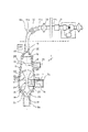
図1を参照すると、参照符号1は、ガス分離を伴う流体混合装置を示している。 Referring to FIG. 1, reference numeral 1 indicates a fluid mixing device with gas separation.
図6に示されているように、この装置1は、対外血液処理のための使い捨て可能なライン2内で働く。この装置は、患者から血液を抜き出すブランチ3と、血液処理ユニット4と、患者に血液を返すためのブランチ5とを有している。
As shown in FIG. 6, the device 1 works in a disposable line 2 for external blood processing. This device has a
更に詳しくは、ユニット4、例えば透析フィルターが、2つのブランチ3と5との間に設けられている。もう一方で、装置1が、患者の血管システムへのアクセスポイントよりもラインの上流にあるリターンブランチ5で働く。
More particularly, a
装置1は、長手方向の対称軸6aを有している収容ボディ6を備えている。このボディ6は、所定量の流体を受けるように設計されて、ブランチ3、5のディメンションよりも相当に大きい径方向のディメンションを有している内容量16を形成している。これによって、以下に説明されるように、流体の速度が減じられ、ガスが有効に分離される。
The device 1 comprises a receiving body 6 having a longitudinal axis of symmetry 6a. The body 6 is designed to receive a predetermined amount of fluid and forms an
装置1と処理部4とは、使用時には、これらの長手方向の軸が垂直方向に延びるように配置される。しかし、装置は、実際には、これの長手方向の軸が傾斜されていても機能し得る。
In use, the apparatus 1 and the
ライン3を通って流れている流体、例えば血液が、垂直方向上方へ流れてユニット4を通り、装置1に入り、患者に返される。この結果、流体の最適な脱気が果たされる。
Fluid, such as blood, flowing through
収容ボディ6は、4つの開口部を有している。ガスを分離される生理液のための第1の入口開口部7と、注入液をコンテナボディ中に運ぶように設計された第2の入口開口部8と、生理液と所定の注入液とが排出され得る出口即ち出口開口部9と、圧力情報を得るためにサービスライン11に接続されるか外部環境に直接的に接続されるように設計された第4の開口部10とを有している。
The housing body 6 has four openings. A first inlet opening 7 for a physiological fluid from which gas is separated, a second inlet opening 8 designed to carry the infusion into the container body, a physiological fluid and a predetermined infusion Having an outlet or
更に詳しくは、第1の入口開口部7は、収容ボディの内部と連通していて生理液を運ぶ管12が取着され得る管状部材7aによって形成されている。第1の入口開口部7とこれに付随した管状部材7aとは、収容ボディに正接するように配置されている。
More specifically, the
第2の入口開口部8が、第1の入口開口部7から離間されて、これの上方に配置されている。 この第2の入口開口部は、収容ボディ6の軸6aの方へと中心に向けられていることに注意したい。
A second inlet opening 8 is spaced apart from the
出口開口部9は、収容ボディの下端部に配置された管状チャネル9aによって形成されており、血液か、必要な場合は注入液と混合された血液かの漸進的な排出を可能にしている。
The
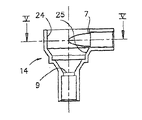
共に組み立てられた2つの半体13、14によって形成された構成を有している収容ボディ6は、ガイド部材17が働くボディの内容量16を定める能動面15を有している。
The receiving body 6, which has a configuration formed by two
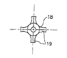
ガイド部材17は、以下に示されるように、流体と接触し、これをガイドするように設計された連続的な外形を備えているこれ自身の能動面18を有している。実際には、ガイド部材は、複数の上記開口部から入ってくる流体によって実際に占められ得る収容ボディの内容量を小さくするように設計された、所定の固体か、内部が中空の回転固形物かである。ガイド部材17は、径方向支持部19(図7を参照)を備えている支持構造体を用いて、ボディ6に取着されている。径方向支持部は、一定の角度間隔で離間され、ガイド部材と収容ボディとの間に配置されている。ガイド部材は、ボディ6と同軸上に延び、出口開口部9の上方に、軸方向でこれから離間されるように配置されている。
The
このように、基本的に環状の外形を有し、第1の入口開口部が直接に開口して開いている第1のチャンバ20が、ガイド部材の能動面18と収容ボディの能動面15との間に形成されている。
In this way, the
収容ボディの能動面15とガイド部材の能動面18とは、互いに面しており、フローのアクセス正接方向に対して横方向に延びた共有の対称軸を中心とした回転面の形に成形されている。能動面15、18の幾何学的な構成と相対的位置とが、第1のアクセス開口部の正接方向と相まって、第1の開口部7からガイド部材の周りに入ってきた血液の回転する動きを生み出す。この回転する動きが、径方向外方に向かう、比較的低い質量(<10マイクロリットル)を有している気泡の動きを促進させる。もう一方で、比較的大きな泡は、ガイド部材の表面付近に集まろうとする。こうした泡は、ガイド部材の外形によって、開口部10に向かって動くようにされる。
The
ガイド部材17は、詳しくは、中央部21と、出口開口部に面している第1の端部22と、この第1の端部に軸方向で対向している第2の端部23とを有している。第1の端部22は、径方向のディメンションが出口開口部に向けて漸進的に小さくなる断面を有している。図示されている例では、第1の端部は、この頂部が出口開口部に面している円錐形である。第2の端部23は、径方向のディメンションが出口開口部から離れるにつれて漸進的に小さくなる断面を有している。
Specifically, the
また、示されている例で、第2の端部は、これの頂部が出口開口部から離れたほうに面する円錐形状にされている。中央部21は、最小の径方向ディメンションを有する中間領域を形成するように径方向のディメンションが端部から離れるにつれて漸進的に小さくなる断面を有している。更に詳しくは、この中央部は、長手方向の断面で湾曲された外形を有している。中央部のこの特別な形状によって、ガイド部材17に集まった気泡が、このガイド部材の外形に基本的に従った所定の通路に沿って上昇しやすくされている。
Also, in the example shown, the second end has a conical shape with its top facing away from the outlet opening. The
言い換えれば、ガイド部材は、一定の外形(円形が好ましい)を備えた断面を有している。その外形では、径方向のディメンションが、この部材の中央部から軸方向で対向した2つの端部に向けて、最初に大きく、次に小さくなっており、かくして、上記の円錐形の端部22、23を形成している。
In other words, the guide member has a cross section with a certain outer shape (preferably circular). In its outer shape, the radial dimension is first large and then small from the central part of the member towards the two axially opposite ends, thus the
収容ボディ6の幾何学が、説明される。 The geometry of the containing body 6 will be explained.
図1では、ボディ6の能動面15が、軸方向で複数の連続した領域に分割されている。最大の径方向のディメンションと一定の半径とを有している第1の領域24が、ガイド部材の中央部21の周りに延びている。径方向のディメンションが出口開口部に向けて漸進的に小さくなっている第2の領域25が、第1の領域24に続いて、基本的にガイド部材の第1の端部の周りに延びている。径方向のディメンションが出口開口部から離れるにつれて漸進的に小さくなっている第3の領域26が、第2の領域と反対の端部で、第1の領域に続いて、基本的にガイド部材の第2の端部の周りに延びている。
In FIG. 1, the
添付図面に明らかに示されているように、第1の入口開口部は、第1のチャンバ20の、第1の領域24へと開口している。かくして、入ってくる流体が、所定の円形の通路に従い、効果的に減速される。
As clearly shown in the accompanying drawings, the first inlet opening opens into the
ガイド部材17によって、第1のチャンバ内のフローは、収容ボディの軸を中心に回転する。この際、このフローは、第1のチャンバ20の中央領域に入るようにされることも、流量がゼロである領域を生じさせることもない。よどんだポイントと量がゼロの領域とがないことによって、排出出口への吸い上げ発生の増加が効果的に妨げられ、この結果、悪影響となる泡の返送と流体の実際的に制御不可能な流れとを防ぐことができる。
The
上述されたように、収容ボディは、また、第1の入口開口部7の上方に配置されて収容ボディに第2の流体を運ぶように設計されたライン27に接続された第2の入口開口部8を有している。通常は、注入液が、この流体と血液か他の生理液とを混合するために、上記のライン27を通って収容ボディ中へと案内される。
As mentioned above, the receiving body is also a second inlet opening connected above the
特に、収容ボディは、第1のチャンバ20と軸方向で連続したところで環状通路29を経てこれと連通するようにガイド部材の上方に配置された、少なくとも第2のチャンバ28を有している。
In particular, the housing body has at least a
第2の入口開口部8は、第2のチャンバに直接開口しており、生理液の上方にこれと接触しながら延びる注入液の層を作り出す。 The second inlet opening 8 opens directly into the second chamber and creates a layer of infusate that extends in contact with and above the physiological fluid.
第2の開口部は、アクセス方向7bが第2の開口部8のアクセス方向に平行になるように配置されていることに注意したい。更に詳しくは、図4及び5に示されているように、向き7bと8bとは、平行だがずれており、即ち、互いから離間されている垂直平面上に配置されている。
Note that the second opening is arranged such that the
かくして、混合の接点が、第1のチャンバ内の血液などの生理液と、第2のチャンバに入ってくる注入液との間に形成される。 Thus, a mixing contact is formed between a physiological fluid such as blood in the first chamber and the infusate entering the second chamber.
2つの流体の均等かつ迅速な混合と、これと同時に行われる脱気とは、対応する開口部7と8との相対的位置付け及び収容ボディとガイド部材との相互作用によって生理液に与えられた回転する動きにより、明らかに促進される。
The equal and rapid mixing of the two fluids and the simultaneous degassing were imparted to the physiological fluid by the relative positioning of the
更に、空気と、第1のチャンバを占めている生理液との直接接触が、第2のチャンバ内に注入液層を与えることによって妨げられる。 Furthermore, direct contact between the air and the physiological fluid occupying the first chamber is prevented by providing an infusate layer in the second chamber.
図示されている例では、血液か他の生理液のフローが第1の開口部を約450ml/分の流量で流れ、食塩水が第2の開口部を1ml/分の流量で流れる場合、第2のチャンバ内に厚さ5〜10mmの一定の食塩―血液層を作り出すことが可能である。 In the example shown, if the flow of blood or other physiological fluid flows through the first opening at a flow rate of about 450 ml / min and the saline flows through the second opening at a flow rate of 1 ml / min, It is possible to create a constant saline-blood layer with a thickness of 5-10 mm in two chambers.
この層の厚さは、効果的な脱気と、流体の最適な混合との両方のために、2mmより大きく、収容ボディの内面の最大直径よりも小さくされる。ここで示されているような例の場合、最大の厚さは、20mmである。 The thickness of this layer is greater than 2 mm and smaller than the maximum diameter of the inner surface of the containing body for both effective degassing and optimal mixing of the fluid. For the example as shown here, the maximum thickness is 20 mm.
ライン27に沿った流体の供給は、制御ユニット36によって制御され得るポンプ27aを用いて調節される。このユニット36は、ポンプ27aを制御し、連続モードか間欠モードのいずれかで指定時間間隔ごとに指定の流量を与えるようにプログラムされている。つまり、制御ユニットは、指定された一定の流量か、指定のプロファイルに従って時間が経つにつれて変化する流量かに従うこと、即ち、最終的には、間欠モードで指定の時間間隔ごとに指定の量の流体を供給するようにプログラムされ得る。
The fluid supply along the
ライン27を通る実際のフローを測定する装置が、制御ユニット36と相互作用する。この測定装置は、例えば、液体コンテナ27cを計量して、処理中のコンテナの実際の重さに関連する情報をユニット36に送るように設計された計量マシン27bを有している。代わりに、制御ユニットと相互作用する流量計が使用されてもよい。
A device that measures the actual flow through
制御ユニットは、指定の範囲内の厚さを有している注入液の層が常に存在し、これが血液の上方に位置されるように、血液ポンプ3aと注入ポンプ27aとの流量を制御し得る。
The control unit may control the flow rate of the blood pump 3a and the
最後に、収容ボディは、軸方向で第2のチャンバに連続され、流体から分離されたガスを保持及び回収するように設計された第3のチャンバ30を有している。この第3のチャンバは、収容ボディの上部で、理論上の液体レベルBLより上に延びている。
Finally, the containment body has a
図示されている例では、第3のチャンバ30は、円錐形で、これの理論上の容量は、レベルBLによって下から、第4の開口部によって上から規定されている。第4の開口部は、収容ボディの内容量、特に第3のチャンバ30の内容量を、サービスラインか、直接的に外部環境に接続している。
In the example shown, the
図示されている例では、サービスライン11が、第1の端部11aが第3のチャンバ30と連通するように配置され、共働するように第2の端部11bが圧力センサー部材31に接続される形で、提供されている。
In the illustrated example, the
上述された例に代わって、圧力センサー部材34が、装置1よりもラインの下流で働くようにされてもよい。
As an alternative to the example described above, the
少なくとも1つの疎水性の膜32が、共働するようにサービスラインの中間領域11cに関連付けられており、液体が圧力センサー(設けられている場合)にアクセスするのを防ぎ、センサー側と、生理液が存在して流れている側とを無菌状態で確実に分離する。
At least one
第3のチャンバは、圧力の最小値から最大値までの範囲(例えば100〜350mmHg)内で圧力が増しても、サービスライン11中への液体の侵入を全く許さず、代わりに、第3のチャンバ内に一定のガススペースを残すような容量を有している。
The third chamber does not allow any liquid to enter the
様々の作業モードが、流体から漸進的に分離される、即ち、何らかの形で装置1まで到達するガスのレベルを制御するように提供され得ることに注意したい。 Note that various working modes can be provided to control the level of gas that is progressively separated from the fluid, i.e., somehow reaches the device 1.
1.完全手動モード
少なくとも1つのアクセス区域33が、サービスライン11内に設けられ、使用者が完全手動で(シリンジを用いて)ガスを取り除くことを可能にさせる。
1. Fully manual mode At least one
2.半自動モード
サービスライン11が、圧力センサー31に接続されている。このセンサーは、ラインの下流で、ソレノイド弁34と空気ポンプ35とに接続されている。弁とポンプとは、ガスをサービスラインに送るか、ガスをサービスラインから排出するために使用され得る。収容ボディ内で維持されるべき液体の作業レベル(operating level)がBLによって示されている場合、使用者は、BLに到達するまでこのレベルを一方向もしくは他方向に動かすために、例えばキーパッドを用いて、圧空ポンプと弁回路とを制御し得る。
2. Semi-automatic mode The
3.自動モード
完全自動モードでの動作のために、例えば光学、超音波、もしくは他のタイプの液体レベルセンサーLLSが、使用される。センサーLLSは、レベルBLよりも上に配置されている。レベルセンサーLLSは、収容ボディの上部か、この近くかで働く。または、レベルセンサーLLSは、チュービングの一部分11a、例えば、基本的に図1に示されているような第4の開口部10に隣接したチュービングの端部領域で働くようにもされ得る。制御ユニット36は、センサーLLSに接続され、液体レベルをBL付近に維持させるように、ポンプ35とソレノイド弁34とを操作する。更に詳しくは、制御ユニットは、LLSが液体の存在を示している場合、
a)LLSと第4の開口部との間の容量と等しい体積V1を第3のチャンバに向かって動かすようにポンプ35を駆動させることと、
b)LLSが液体の存在を継続的に示す間に第3のチャンバからガスを排出するようにポンプ35を駆動させることと、
c)Vcが第3のチャンバの容量である場合に、V1+Vcに等しい液体の体積V2を第3のチャンバに向かって動かすようにポンプ35を駆動させることとの従属工程の実施を命令し得る。
3. Automatic mode For operation in the fully automatic mode, for example, optical, ultrasonic or other types of liquid level sensors LLS are used. The sensor LLS is disposed above the level BL. The level sensor LLS works at or near the top of the containing body. Alternatively, the level sensor LLS can also be made to work in the
a) driving the
b) driving
If c) V c is the volume of the third chamber, implementation dependent process of driving the
LLSが液体の存在を示していない場合は、上述した3つの工程a)、b)及びc)が、指定の時間間隔ごとに自動的に連続して繰り返される。 If the LLS does not indicate the presence of liquid, the three steps a), b) and c) described above are automatically and continuously repeated at specified time intervals.
上述した自動処理が、センサーLLSが働いている区域で液体が静止し続けないようにするという大きな利点を有していることに注意したい。これは、第2の開口部から注入されて食塩注入液が存在している場合でさえも、液体の上層が所定%の細胞物質を常に有していることから、相当に重要である。細胞物質は、長期的に見ると、センサーLLSの正確な働きによい影響を与え、その結果、液体レベルの効果的なモニタリングを可能にするエンクラステーションを発生させる可能性がある。 Note that the automatic processing described above has the great advantage of keeping the liquid from standing still in the area where the sensor LLS is working. This is of considerable importance since the upper layer of the liquid always has a certain percentage of cellular material even when a saline infusion is present through the second opening. Cellular material, in the long run, can positively affect the correct functioning of the sensor LLS, and as a result, can generate enclaves that allow effective monitoring of liquid levels.
また、説明されたレベルのモニタリング処置によって、液体のフローがサービスライン11に向かうのを防ぎ、これによって、安全性を確実にし、装置1内の流体の完全無菌状態を保証する更なる手段を提供できることに、注意したい。
Also, the described level of monitoring procedure prevents liquid flow from going to the
Claims (28)
前記ボディ内に少なくとも部分的に収容され、前記生理液に接触してこれをガイドするように設計された連続的な能動面を有しているガイド部材と、
このガイド部材の能動面と前記収容ボディの内側能動面との間に形成されている環状の第1のチャンバとを具備し、
前記ガイド部材は、
中央部と、
前記出口開口部に面している第1の端部と、
軸方向で前記第1の端部に対向し、ガイド部材の上方に延びた第2のチャンバに面している第2の端部とを有し、
前記中央部は、最小の径方向ディメンションを有している中央領域を形成するように、径方向のディメンションが前記両端部から離れるにつれて漸進的に小さくなる断面を有していることを特徴としている、装置。A first inlet opening for a physiological fluid having an inner active surface and disposed in an access tangential direction; and at least one outlet opening for said physiological fluid spaced from the first inlet opening In a gas separation device for physiological fluid comprising a housing body comprising at least
A guide member that is at least partially contained within the body and has a continuous active surface designed to contact and guide the physiological fluid;
An annular first chamber formed between the active surface of the guide member and the inner active surface of the containing body ;
The guide member is
In the center,
A first end facing the outlet opening;
A second end facing the first end in the axial direction and facing the second chamber extending above the guide member;
The central portion has a cross-section that gradually decreases as the radial dimension moves away from the ends so as to form a central region having the smallest radial dimension. , Equipment.
最大の径方向のディメンションを有し、ガイド部材の中央部の周りに延びている第1の領域と、
径方向のディメンションが出口開口部に向けて漸進的に小さくなり、前記第1の領域に続いて基本的にガイド部材の第1の端部の周りに延びている第2の領域と、
径方向のディメンションが出口開口部から離れるにつれて漸進的に小さくなり、前記第1の領域に続いて基本的にガイド部材の第2の端部の周りに延びている第3の領域とを有していることを特徴としている、請求項1の装置。The active surface of the containing body is
A first region having a maximum radial dimension and extending around a central portion of the guide member;
A second region having a radial dimension that progressively decreases toward the outlet opening and extends essentially around the first end of the guide member following the first region;
A third region that progressively decreases as the radial dimension moves away from the outlet opening and that extends essentially around the second end of the guide member following the first region. The apparatus of claim 1 , wherein:
LLSが液体の存在を示しているかどうかを判断する工程と、
もし存在を示している場合には、
a)LLSが働く区域と第4の開口部との間の容量と等しい体積V1を第3のチャンバに向かって動かすように圧空回路を駆動させることと、
b)LLSが液体の存在を継続的に示す間に第3のチャンバからガスを排出させるように圧空回路を駆動させることと、
c)Vcが第3のチャンバの容量である場合に、V1+VCに等しい液体の体積V2を第3のチャンバに向かって動かすように圧空回路を駆動させることとの従属工程を順に実施し、
他方で、LLSが液体の存在を示していない場合には、上述した3つの工程a)、b)及びc)を指定の時間間隔ごとに実施する工程との実施を指示するように設計されている、請求項24の装置。The level sensor LLS works in a section of the service line, and the control unit
Determining whether the LLS indicates the presence of a liquid;
If it is present,
a) driving the pneumatic circuit to move a volume V 1 equal to the volume between the area where the LLS works and the fourth opening towards the third chamber;
b) driving the pneumatic circuit to exhaust gas from the third chamber while the LLS continuously indicates the presence of liquid;
c) sequentially performing the dependent process of driving the pneumatic circuit to move a volume of liquid V 2 equal to V 1 + V C towards the third chamber, where Vc is the volume of the third chamber And
On the other hand, if the LLS does not indicate the presence of liquid, it is designed to instruct the execution of the above-mentioned three steps a), b) and c) at a specified time interval. 25. The apparatus of claim 24 .
第2の入口開口部を通して収容ボディ中に第2の流体を送るための第2のラインと、
前記第1のラインに沿ってフローを作り出すように働くポンプと、
前記第2のラインに沿ってフローを作り出すように働くポンプと、
前記第1及び第2のラインで働く複数のポンプを制御することと、指定の範囲内の厚さを有し、生理液の上方に配置される前記第2の流体の層を、収容ボディ内に一定して存在させるのを確実にすることとをプログラムされた制御ユニットとを具備していることを特徴としている、請求項1の装置。A first line for delivering physiological fluid through the first inlet opening and into the containing body;
A second line for delivering a second fluid through the second inlet opening and into the containing body;
A pump that serves to create a flow along the first line;
A pump that serves to create a flow along the second line;
Controlling a plurality of pumps working in the first and second lines, and having a thickness within a specified range, the second fluid layer disposed above the physiological fluid in the containing body 2. A device according to claim 1, characterized in that it comprises a control unit programmed to ensure a constant presence.
Applications Claiming Priority (3)
| Application Number | Priority Date | Filing Date | Title |
|---|---|---|---|
| IT2002MI001390A ITMI20021390A1 (en) | 2002-06-24 | 2002-06-24 | GAS SEPARATION DEVICE FOR PHYSIOLOGICAL FLUIDS |
| IT2002MI001389A ITMI20021389A1 (en) | 2002-06-24 | 2002-06-24 | MIXING DEVICE FOR FLUIDS WITH GAS SEPARATION |
| PCT/IB2003/002281 WO2004000391A1 (en) | 2002-06-24 | 2003-05-26 | Gas separation devices |
Publications (2)
| Publication Number | Publication Date |
|---|---|
| JP2005530543A JP2005530543A (en) | 2005-10-13 |
| JP4358736B2 true JP4358736B2 (en) | 2009-11-04 |
Family
ID=30002072
Family Applications (1)
| Application Number | Title | Priority Date | Filing Date |
|---|---|---|---|
| JP2004515104A Expired - Lifetime JP4358736B2 (en) | 2002-06-24 | 2003-05-26 | Gas separator |
Country Status (10)
| Country | Link |
|---|---|
| US (1) | US7517387B2 (en) |
| EP (2) | EP2055331B1 (en) |
| JP (1) | JP4358736B2 (en) |
| KR (1) | KR100947006B1 (en) |
| AT (1) | ATE426420T1 (en) |
| AU (1) | AU2003233023B2 (en) |
| CA (2) | CA2729519C (en) |
| DE (1) | DE60326847D1 (en) |
| ES (2) | ES2473627T3 (en) |
| WO (1) | WO2004000391A1 (en) |
Families Citing this family (67)
| Publication number | Priority date | Publication date | Assignee | Title |
|---|---|---|---|---|
| DE10224750A1 (en) | 2002-06-04 | 2003-12-24 | Fresenius Medical Care De Gmbh | Device for the treatment of a medical fluid |
| US7201870B2 (en) | 2003-01-14 | 2007-04-10 | Medtronic, Inc. | Active air removal system operating modes of an extracorporeal blood circuit |
| US7204958B2 (en) | 2003-01-14 | 2007-04-17 | Medtronic, Inc. | Extracorporeal blood circuit air removal system and method |
| US7488448B2 (en) * | 2004-03-01 | 2009-02-10 | Indian Wells Medical, Inc. | Method and apparatus for removal of gas bubbles from blood |
| US8029454B2 (en) | 2003-11-05 | 2011-10-04 | Baxter International Inc. | High convection home hemodialysis/hemofiltration and sorbent system |
| US7935074B2 (en) * | 2005-02-28 | 2011-05-03 | Fresenius Medical Care Holdings, Inc. | Cassette system for peritoneal dialysis machine |
| JP4839030B2 (en) * | 2005-07-06 | 2011-12-14 | テルモ株式会社 | Extracorporeal circulation device |
| JP4839028B2 (en) * | 2005-07-06 | 2011-12-14 | テルモ株式会社 | Bubble removal device |
| JP4839029B2 (en) * | 2005-07-06 | 2011-12-14 | テルモ株式会社 | Bubble removal device |
| US8197231B2 (en) | 2005-07-13 | 2012-06-12 | Purity Solutions Llc | Diaphragm pump and related methods |
| US7871391B2 (en) | 2005-10-21 | 2011-01-18 | Fresenius Medical Care Holdings, Inc. | Extracorporeal fluid circuit |
| DE102005058012B4 (en) | 2005-12-05 | 2008-08-21 | Fresenius Medical Care Deutschland Gmbh | A method for blowing out a wetted hydrophobic filter and apparatus for carrying out the method |
| WO2008053287A1 (en) * | 2006-10-31 | 2008-05-08 | Ehud Milo | Extraction of gas from infused fluid |
| DE102007036125A1 (en) * | 2007-08-01 | 2009-02-05 | Becker, Franz Ferdinand, Dr.-Ing. | Bloodline system for extracorporeal applications such as dialysis machines |
| FR2920314B1 (en) | 2007-09-05 | 2010-07-30 | Gambro Lundia Ab | EXTRACORPOREAL BLOOD TREATMENT CIRCUIT AND LINE HAVING INFUSION SITE FOR THE OPTIMIZED MIXING OF FLUIDS |
| US7892197B2 (en) | 2007-09-19 | 2011-02-22 | Fresenius Medical Care Holdings, Inc. | Automatic prime of an extracorporeal blood circuit |
| EP3150238B1 (en) | 2007-09-19 | 2018-03-14 | Fresenius Medical Care Holdings, Inc. | Dialysis systems and related components |
| JP5295249B2 (en) | 2007-09-19 | 2013-09-18 | フレゼニウス メディカル ケア ホールディングス インコーポレーテッド | Extracorporeal medical fluid circuit component and apparatus including the component |
| EP2372077A3 (en) * | 2007-09-26 | 2014-03-12 | Cameron International Corporation | Choke assembly |
| US7892332B2 (en) * | 2007-10-01 | 2011-02-22 | Baxter International Inc. | Dialysis systems having air traps with internal structures to enhance air removal |
| ES2376666T3 (en) * | 2007-10-04 | 2012-03-15 | Gambro Lundia Ab | INFUSION DEVICE. |
| US8663463B2 (en) | 2009-02-18 | 2014-03-04 | Fresenius Medical Care Holdings, Inc. | Extracorporeal fluid circuit and related components |
| US8192401B2 (en) | 2009-03-20 | 2012-06-05 | Fresenius Medical Care Holdings, Inc. | Medical fluid pump systems and related components and methods |
| DE102009030283A1 (en) * | 2009-06-24 | 2011-01-05 | Fresenius Medical Care Deutschland Gmbh | Chamber for a blood treatment system, blood tube system and blood treatment system |
| CA2767668C (en) | 2009-07-15 | 2017-03-07 | Fresenius Medical Care Holdings, Inc. | Medical fluid cassettes and related systems and methods |
| US8720913B2 (en) | 2009-08-11 | 2014-05-13 | Fresenius Medical Care Holdings, Inc. | Portable peritoneal dialysis carts and related systems |
| US8753515B2 (en) | 2009-12-05 | 2014-06-17 | Home Dialysis Plus, Ltd. | Dialysis system with ultrafiltration control |
| US9220832B2 (en) | 2010-01-07 | 2015-12-29 | Fresenius Medical Care Holdings, Inc. | Dialysis systems and methods |
| US8500994B2 (en) | 2010-01-07 | 2013-08-06 | Fresenius Medical Care Holdings, Inc. | Dialysis systems and methods |
| US8425780B2 (en) | 2010-03-11 | 2013-04-23 | Fresenius Medical Care Holdings, Inc. | Dialysis system venting devices and related systems and methods |
| US8501009B2 (en) | 2010-06-07 | 2013-08-06 | State Of Oregon Acting By And Through The State Board Of Higher Education On Behalf Of Oregon State University | Fluid purification system |
| IT1400562B1 (en) * | 2010-06-18 | 2013-06-14 | Bellco Srl | DIALYSIS MACHINE INCLUDING A CASSETTE OF PERFECT TYPE. |
| US8967852B2 (en) * | 2010-09-17 | 2015-03-03 | Delavan Inc | Mixers for immiscible fluids |
| DE102010053973A1 (en) | 2010-12-09 | 2012-06-14 | Fresenius Medical Care Deutschland Gmbh | Medical device with a heater |
| US8506684B2 (en) | 2010-12-15 | 2013-08-13 | Fresenius Medical Care Holdings, Inc. | Gas release devices for extracorporeal fluid circuits and related methods |
| US9694125B2 (en) | 2010-12-20 | 2017-07-04 | Fresenius Medical Care Holdings, Inc. | Medical fluid cassettes and related systems and methods |
| US8382711B2 (en) | 2010-12-29 | 2013-02-26 | Baxter International Inc. | Intravenous pumping air management systems and methods |
| GB2486910B (en) * | 2010-12-30 | 2014-05-14 | Cameron Int Corp | Apparatus and method for fluid separation |
| US9624915B2 (en) | 2011-03-09 | 2017-04-18 | Fresenius Medical Care Holdings, Inc. | Medical fluid delivery sets and related systems and methods |
| JP6062920B2 (en) | 2011-04-21 | 2017-01-18 | フレセニウス メディカル ケア ホールディングス インコーポレーテッド | Medical fluid pumping system and related devices and methods |
| ES2640953T3 (en) | 2011-10-07 | 2017-11-07 | Outset Medical, Inc. | Purification of heat exchange fluid for a dialysis system |
| US9186449B2 (en) | 2011-11-01 | 2015-11-17 | Fresenius Medical Care Holdings, Inc. | Dialysis machine support assemblies and related systems and methods |
| US9610392B2 (en) | 2012-06-08 | 2017-04-04 | Fresenius Medical Care Holdings, Inc. | Medical fluid cassettes and related systems and methods |
| US9500188B2 (en) | 2012-06-11 | 2016-11-22 | Fresenius Medical Care Holdings, Inc. | Medical fluid cassettes and related systems and methods |
| US9561323B2 (en) | 2013-03-14 | 2017-02-07 | Fresenius Medical Care Holdings, Inc. | Medical fluid cassette leak detection methods and devices |
| US9433721B2 (en) | 2013-06-25 | 2016-09-06 | Fresenius Medical Care Holdings, Inc. | Vial spiking assemblies and related methods |
| US10117985B2 (en) | 2013-08-21 | 2018-11-06 | Fresenius Medical Care Holdings, Inc. | Determining a volume of medical fluid pumped into or out of a medical fluid cassette |
| JP6657186B2 (en) | 2014-04-29 | 2020-03-04 | アウトセット・メディカル・インコーポレイテッドOutset Medical, Inc. | Dialysis system and method |
| JP6517023B2 (en) | 2015-01-23 | 2019-05-22 | 日機装株式会社 | Blood purification device |
| JP6605817B2 (en) * | 2015-03-03 | 2019-11-13 | 日機装株式会社 | Air trap chamber |
| JP6416661B2 (en) * | 2015-03-03 | 2018-10-31 | 日機装株式会社 | Air trap chamber |
| JP6724901B2 (en) * | 2015-03-23 | 2020-07-15 | ニプロ株式会社 | Mixing chamber |
| JP6516559B2 (en) | 2015-05-21 | 2019-05-22 | 日機装株式会社 | Blood purification device |
| GB201509911D0 (en) * | 2015-06-08 | 2015-07-22 | Oxyless Ltd | Dialysis bloodline set and method of use |
| US9974942B2 (en) | 2015-06-19 | 2018-05-22 | Fresenius Medical Care Holdings, Inc. | Non-vented vial drug delivery |
| EP3315150B1 (en) | 2015-06-24 | 2020-12-09 | Nikkiso Co., Ltd. | Blood purifying device |
| EP3365040A4 (en) | 2015-10-19 | 2019-06-12 | CONMED Corporation | Liquid-gas separator |
| US9945838B2 (en) | 2015-12-17 | 2018-04-17 | Fresenius Medical Care Holdings, Inc. | Extracorporeal circuit blood chamber having an integrated deaeration device |
| JP6111351B1 (en) | 2016-01-25 | 2017-04-05 | 日機装株式会社 | Blood purification equipment |
| US10625009B2 (en) * | 2016-02-17 | 2020-04-21 | Baxter International Inc. | Airtrap, system and method for removing microbubbles from a fluid stream |
| EP4039286A1 (en) | 2016-08-19 | 2022-08-10 | Outset Medical, Inc. | Peritoneal dialysis system and methods |
| JP6998112B2 (en) | 2016-09-12 | 2022-01-18 | 日機装株式会社 | Blood purification device |
| JP6826852B2 (en) | 2016-09-23 | 2021-02-10 | 日機装株式会社 | Blood purification device |
| DE102016122660A1 (en) * | 2016-11-24 | 2018-05-24 | B. Braun Avitum Ag | Medical air separator for use in blood treatments |
| US20210196882A1 (en) * | 2018-05-17 | 2021-07-01 | Gambro Lundia Ab | Treatment apparatus with gas separation device level controls and methods |
| US11964090B2 (en) * | 2019-02-28 | 2024-04-23 | Qidni Labs, Inc. | Systems and methods of gas removal from a wearable device |
| US11642459B2 (en) * | 2020-01-15 | 2023-05-09 | Becton, Dickinson And Company | System and method for air removal |
Family Cites Families (98)
| Publication number | Priority date | Publication date | Assignee | Title |
|---|---|---|---|---|
| US2758597A (en) | 1955-01-24 | 1956-08-14 | Cutter Lab | Blood transfusion apparatus |
| US3631654A (en) | 1968-10-03 | 1972-01-04 | Pall Corp | Gas purge device |
| US3677248A (en) | 1970-08-27 | 1972-07-18 | American Hospital Supply Corp | Surgical irrigation apparatus and method of using same |
| FR2106918A5 (en) | 1970-09-29 | 1972-05-05 | Rhone Poulenc Sa | |
| US3939078A (en) | 1974-04-19 | 1976-02-17 | Johnson & Johnson | Extracorporeal filter |
| GB1506555A (en) * | 1974-05-24 | 1978-04-05 | Johnson & Johnson | Blood reservoir |
| US3967620A (en) | 1974-09-10 | 1976-07-06 | United States Surgical Corporation | Volume limiting chamber |
| US3909045A (en) | 1974-10-10 | 1975-09-30 | Gen Electric | Tubing joint for adhesive bonding |
| US4083706A (en) | 1974-10-25 | 1978-04-11 | Wiley Corless W | Sterile trap accessory for use with surgical aspirator |
| US3964479A (en) | 1974-11-20 | 1976-06-22 | Cobe Laboratories, Inc. | Extracorporeal blood circulation system and drip chamber with adjustable blood level |
| US4198971A (en) | 1975-05-21 | 1980-04-22 | United States Surgical Corporation | Drip chamber with air vent |
| US4009107A (en) | 1975-10-08 | 1977-02-22 | Baxter Laboratories, Inc. | Multi-level support member for use with semipermeable membrane |
| US3993062A (en) | 1975-11-03 | 1976-11-23 | Baxter Laboratories, Inc. | Hydrophobic valve |
| US4030495A (en) | 1975-11-07 | 1977-06-21 | Baxter Travenol Laboratories, Inc. | Twin check valve pump system having fail-safe characteristic |
| US4231871A (en) | 1977-06-10 | 1980-11-04 | Cordis Dow Corp. | Artificial kidney and method for making same |
| US4379452A (en) | 1977-10-18 | 1983-04-12 | Baxter Travenol Laboratories, Inc. | Prepackaged, self-contained fluid circuit module |
| US4190426A (en) | 1977-11-30 | 1980-02-26 | Baxter Travenol Laboratories, Inc. | Gas separating and venting filter |
| US4227525A (en) | 1978-03-30 | 1980-10-14 | Valleylab | Intravenous administration set |
| US4256105A (en) | 1979-02-28 | 1981-03-17 | Abbott Laboratories | Equipment sets having reduced diameter primary tube for the sequential administration of medical liquids at dual flow rates |
| US4263808A (en) | 1979-03-26 | 1981-04-28 | Baxter Travenol Laboratories, Inc. | Noninvasive pressure monitor |
| NL7905463A (en) | 1979-07-12 | 1981-01-14 | Noord Nederlandsche Maschf | PUMP. |
| US4637813A (en) | 1979-12-06 | 1987-01-20 | Baxter Travenol Laboratories, Inc. | Blood processing assembly including a prepackaged fluid circuit module |
| US4526515A (en) | 1979-12-06 | 1985-07-02 | Baxter Travenol Laboratories, Inc. | Fluid pumping assembly including a prepackaged fluid circuit module |
| US4324662A (en) | 1979-12-28 | 1982-04-13 | Baxter Travenol Laboratories, Inc. | Flow reversal in a dialyzer |
| US4293413A (en) | 1979-12-28 | 1981-10-06 | Baxter Travenol Laboratories, Inc. | Dialyzer blood circuit and bubble traps |
| US4331540A (en) | 1980-04-21 | 1982-05-25 | Baxter Travenol Laboratories, Inc. | Process for draining dialysate from artificial kidney |
| DE3271925D1 (en) | 1981-04-16 | 1986-08-14 | Kuraray Co | Line for use in body fluid treatment |
| US4412916A (en) | 1981-06-24 | 1983-11-01 | Cordis Dow Corp. | Airless artificial kidney assembly |
| US4447230A (en) | 1981-08-05 | 1984-05-08 | Quest Medical, Inc. | Intravenous administration set assembly |
| DE3203954A1 (en) | 1982-02-05 | 1983-08-18 | Dr. Eduard Fresenius, Chemisch-pharmazeutische Industrie KG, 6380 Bad Homburg | DEVICE FOR REMOVING LIQUIDS FROM PARTICULARLY STERILY LOCKED VESSELS |
| JPS58190447A (en) | 1982-04-30 | 1983-11-07 | 株式会社クラレ | Pulse generating apparatus |
| US4534757A (en) | 1982-06-14 | 1985-08-13 | Alza Corporation | Device for releasing active ingredient, insertable in a system of parenteral administering the ingredient |
| US4493706A (en) | 1982-08-12 | 1985-01-15 | American Hospital Supply Corporation | Linear peristaltic pumping apparatus and disposable casette therefor |
| US4568330A (en) | 1983-06-02 | 1986-02-04 | Minnesota Mining And Manufacturing Company | Cardioplegia delivery system with improved bubble trap |
| JPS59228849A (en) | 1983-06-10 | 1984-12-22 | テルモ株式会社 | Apparatus for removing air bubbles in liquid |
| SE451541B (en) | 1983-06-30 | 1987-10-19 | Gambro Lundia Ab | EXTRACORPORAL BLOOD TREATMENT SYSTEM |
| US4568366A (en) | 1983-08-30 | 1986-02-04 | Baxter Laboratories, Inc. | In-line filter |
| US4572724A (en) | 1984-04-12 | 1986-02-25 | Pall Corporation | Blood filter |
| US4571244A (en) | 1984-05-07 | 1986-02-18 | Biogenesis, Inc. | System for removing gas bubbles from liquids |
| SE458340B (en) | 1984-06-18 | 1989-03-20 | Gambro Lundia Ab | BLOOD FILTERING SYSTEM AND DROP AND / OR EXPANSION ROOMS INTENDED FOR THIS SYSTEM |
| US4623333A (en) | 1984-09-28 | 1986-11-18 | Fried Steven J | Fried-Grant rapid solution administration set with integral heat exchanger |
| US4643713A (en) | 1984-11-05 | 1987-02-17 | Baxter Travenol Laboratories, Inc. | Venous reservoir |
| US4650454A (en) | 1985-02-21 | 1987-03-17 | Moll Richard J | Roller for glue applying folding machines |
| US4664800A (en) | 1985-03-18 | 1987-05-12 | Burron Medical Inc. | Micron chamber I.V. with support ring |
| GB8527646D0 (en) | 1985-11-08 | 1985-12-11 | Cox J A | Devices for sampling drainage |
| BE905615R (en) | 1986-09-10 | 1987-04-17 | Hombrouckx Remi O J | METHOD AND EQUIPMENT FOR SINGLE NEEDLE MODIALYSIS. |
| EP0282539B1 (en) | 1986-09-12 | 1992-01-29 | Memtec Limited | Hollow fibre filter cartridge and header |
| US4988342A (en) | 1987-03-02 | 1991-01-29 | Atrium Medical Corporation | Improved fluid recovery system |
| US4900308A (en) | 1987-05-27 | 1990-02-13 | Level 1 Technologies, Inc. | Gas elimination device |
| CA1311694C (en) | 1987-05-27 | 1992-12-22 | Wesley H. Verkaart | Gas elimination device in which gas exits through a permeable membrane |
| US4806135A (en) * | 1988-03-01 | 1989-02-21 | Siposs George G | Bubble trap for phase-separating gas bubbles from flowing liquids |
| US4886431A (en) | 1988-04-29 | 1989-12-12 | Cole-Parmer Instrument Company | Peristaltic pump having independently adjustable cartridges |
| US4950245A (en) | 1988-07-08 | 1990-08-21 | I-Flow Corporation | Multiple fluid cartridge and pump |
| DE8901513U1 (en) | 1988-08-20 | 1989-04-06 | Huebner, Karl-Alexander, 7500 Karlsruhe, De | |
| DE3832028A1 (en) | 1988-09-21 | 1990-03-22 | Minh Bach Dr Ing Dr Med Quang | DEVICE FOR VENTING LIQUIDS FLOWING IN MEDICAL LIQUID SYSTEMS |
| US5046509A (en) | 1988-12-30 | 1991-09-10 | Spacelabs, Inc. | Device for the conditioning, handling and measurement of blood |
| JPH02182404A (en) | 1989-01-09 | 1990-07-17 | Hitachi Seiko Ltd | Punch press device |
| US4932987A (en) * | 1989-05-25 | 1990-06-12 | Jorge Molina | Extra corporeal air eliminator |
| US5126054A (en) | 1990-05-24 | 1992-06-30 | Pall Corporation | Venting means |
| CA2094102A1 (en) | 1992-04-30 | 1993-10-31 | David S. Utterberg | Blood air trap chamber |
| US5578070A (en) | 1992-04-30 | 1996-11-26 | Medisystems Technology Corporation | Blow molded venous drip chamber for hemodialysis |
| EP0646380B1 (en) | 1993-09-01 | 1997-06-25 | Fresenius AG | Air separator |
| US5503801A (en) | 1993-11-29 | 1996-04-02 | Cobe Laboratories, Inc. | Top flow bubble trap apparatus |
| US5591251A (en) | 1993-11-29 | 1997-01-07 | Cobe Laboratories, Inc. | Side flow bubble trap apparatus and method |
| AU7882694A (en) | 1993-11-29 | 1995-06-08 | Cobe Laboratories Inc. | Side flow bubble trap apparatus and method |
| US5421815A (en) | 1993-12-14 | 1995-06-06 | Nof Corporation | Method for blood dialysis using anticoagulent composition |
| US5427509A (en) | 1993-12-22 | 1995-06-27 | Baxter International Inc. | Peristaltic pump tube cassette with angle pump tube connectors |
| US5462416A (en) | 1993-12-22 | 1995-10-31 | Baxter International Inc. | Peristaltic pump tube cassette for blood processing systems |
| US5482440A (en) | 1993-12-22 | 1996-01-09 | Baxter Int | Blood processing systems using a peristaltic pump module with valve and sensing station for operating a peristaltic pump tube cassette |
| CA2142413A1 (en) | 1994-02-15 | 1995-08-16 | Wesley H. Verkarrt | Vortex gas elimination device |
| SE504247C2 (en) * | 1994-03-24 | 1996-12-16 | Gaevle Galvan Tryckkaerl Ab | Vessels for treating fluid |
| US5632894A (en) | 1994-06-24 | 1997-05-27 | Gish Biomedical, Inc. | Arterial blood filter with upwardly inclining delivery inlet conduit |
| US5609571A (en) | 1995-01-26 | 1997-03-11 | Sorin Biomedical Inc. | Apparatus and method of cardioplegia delivery |
| US5591344A (en) | 1995-02-13 | 1997-01-07 | Aksys, Ltd. | Hot water disinfection of dialysis machines, including the extracorporeal circuit thereof |
| US5667485A (en) | 1995-05-01 | 1997-09-16 | Minnesota Mining And Manufacturing Company | Blood reservoir with visible inlet tube |
| US5641144A (en) | 1995-06-07 | 1997-06-24 | Cobe Laboratories, Inc. | Dialyzer holder |
| DE19545404A1 (en) * | 1995-12-06 | 1997-06-12 | Kevin Business Corp | Excretion of air from blood containing air |
| DE19617036C2 (en) | 1996-04-27 | 2003-12-04 | Fresenius Ag | Device for separating gas bubbles from blood |
| DE19620591B4 (en) | 1996-05-22 | 2004-08-26 | Fresenius Medical Care Deutschland Gmbh | Device for removing gases from liquids |
| US5871693A (en) | 1996-06-07 | 1999-02-16 | Minnesota Mining And Manufacturing Company | Modular blood treatment cartridge |
| US5895368A (en) | 1996-09-23 | 1999-04-20 | Medisystems Technology Corporation | Blood set priming method and apparatus |
| US6117342A (en) | 1996-11-26 | 2000-09-12 | Medisystems Technology Corporation | Bubble trap with directed horizontal flow and method of using |
| US5983947A (en) | 1997-03-03 | 1999-11-16 | Medisystems Technology Corporation | Docking ports for medical fluid sets |
| DE19719555A1 (en) * | 1997-05-09 | 1998-11-12 | Kevin Business Corp | Method and device for separating gas from gaseous blood |
| DE19727251C2 (en) | 1997-06-26 | 2002-06-06 | Fresenius Medical Care De Gmbh | Filter device and device for holding it |
| US6010623A (en) | 1997-08-01 | 2000-01-04 | Medisystems Technology Corporation | Bubble trap with flat side |
| US5935093A (en) * | 1997-09-29 | 1999-08-10 | Medtronic, Inc. | Softshell reservoir with integrated cardiotomy reservoir |
| US5961700A (en) | 1997-10-31 | 1999-10-05 | Sims Level 1 | Filter system for removal of gas and particulates from cellular fluids |
| DE19750062A1 (en) | 1997-11-12 | 1999-05-20 | Jostra Medizintechnik Ag | Device for the filtration and degassing of body fluids, especially blood |
| US6193689B1 (en) | 1997-11-19 | 2001-02-27 | Robert W. Woodard | Intravenous liquid flow regulator |
| US6071269A (en) | 1998-05-13 | 2000-06-06 | Medisystems Technology Corporation | Blood set and chamber |
| US6019824A (en) | 1998-06-09 | 2000-02-01 | Medisystems Technology Corporation | Bubble trap chamber |
| DE19852982C1 (en) | 1998-11-17 | 2000-03-16 | Braun Melsungen Ag | Cartridge holder for dialysis machine has lower cheek with outlet connection and upper cheek with inflow connection, with cartridge being insertable between cheeks |
| US6383158B1 (en) | 1998-12-01 | 2002-05-07 | Dsu Medical Corporation | Dialysis pressure monitoring with clot suppression |
| US6251291B1 (en) | 1998-12-28 | 2001-06-26 | Tranfusion Technologies Corporation | Reservoir-and-filter system and method of use |
| DE19925297C1 (en) | 1999-06-02 | 2000-07-13 | Braun Melsungen Ag | Dialysis machine filter cartridge holder uses radial tensioner elements to seal onto cartridge connections when positioned using keyhole holder connections taking cartridge connection grooves. |
| US6325775B1 (en) | 1999-09-03 | 2001-12-04 | Baxter International Inc. | Self-contained, transportable blood processsing device |
| US6451257B1 (en) * | 1999-09-16 | 2002-09-17 | Terumo Kabushiki Kaisha | Arterial blood filter |
-
2003
- 2003-05-26 AU AU2003233023A patent/AU2003233023B2/en not_active Expired
- 2003-05-26 JP JP2004515104A patent/JP4358736B2/en not_active Expired - Lifetime
- 2003-05-26 ES ES09002597.4T patent/ES2473627T3/en not_active Expired - Lifetime
- 2003-05-26 CA CA2729519A patent/CA2729519C/en not_active Expired - Lifetime
- 2003-05-26 ES ES03727824T patent/ES2324707T3/en not_active Expired - Lifetime
- 2003-05-26 CA CA2490174A patent/CA2490174C/en not_active Expired - Lifetime
- 2003-05-26 US US10/518,787 patent/US7517387B2/en active Active
- 2003-05-26 DE DE60326847T patent/DE60326847D1/en not_active Expired - Lifetime
- 2003-05-26 KR KR1020047021179A patent/KR100947006B1/en active IP Right Grant
- 2003-05-26 EP EP09002597.4A patent/EP2055331B1/en not_active Expired - Lifetime
- 2003-05-26 EP EP03727824A patent/EP1519764B1/en not_active Expired - Lifetime
- 2003-05-26 WO PCT/IB2003/002281 patent/WO2004000391A1/en active Application Filing
- 2003-05-26 AT AT03727824T patent/ATE426420T1/en not_active IP Right Cessation
Also Published As
| Publication number | Publication date |
|---|---|
| KR100947006B1 (en) | 2010-03-11 |
| AU2003233023B2 (en) | 2008-05-15 |
| EP2055331A2 (en) | 2009-05-06 |
| ES2324707T3 (en) | 2009-08-13 |
| US7517387B2 (en) | 2009-04-14 |
| EP2055331B1 (en) | 2014-05-14 |
| CA2729519C (en) | 2014-11-18 |
| EP1519764A1 (en) | 2005-04-06 |
| ATE426420T1 (en) | 2009-04-15 |
| JP2005530543A (en) | 2005-10-13 |
| DE60326847D1 (en) | 2009-05-07 |
| WO2004000391A1 (en) | 2003-12-31 |
| CA2490174A1 (en) | 2003-12-31 |
| CA2490174C (en) | 2011-04-19 |
| EP2055331A3 (en) | 2010-10-27 |
| EP1519764B1 (en) | 2009-03-25 |
| KR20060070383A (en) | 2006-06-23 |
| US20050247203A1 (en) | 2005-11-10 |
| AU2003233023A1 (en) | 2004-01-06 |
| CA2729519A1 (en) | 2003-12-31 |
| ES2473627T3 (en) | 2014-07-07 |
Similar Documents
| Publication | Publication Date | Title |
|---|---|---|
| JP4358736B2 (en) | Gas separator | |
| EP0128556B1 (en) | Apparatus for removing bubbles from a liquid | |
| CN100586494C (en) | Integrated blood treatment module | |
| CN1878582B (en) | Degassing device and end-cap assembly for a filter including such a degassing device | |
| EP2099513B1 (en) | A blood transfer chamber | |
| KR20060113704A (en) | Fluid distribution module and extracorporeal blood circuit including such a module | |
| JPH11511686A (en) | Blood processing system | |
| EP0954364A1 (en) | Wide bubble traps | |
| JP2005532105A (en) | Support member for extracorporeal fluid transfer line | |
| EP2209509B1 (en) | Arterial blood filter | |
| US20230052266A1 (en) | Blood reservoir with blood-handling assembly | |
| EP1613371B1 (en) | A device, cartridge and method for solving powder in liquid, when manufacturing a dialysis fluid | |
| CN112020373B (en) | Air trap chamber and extracorporeal circulation circuit | |
| EP3789060B1 (en) | Air trap chamber and extracorporeal circulation circuit | |
| CN113490518A (en) | Dialyzer and dialysis apparatus |
Legal Events
| Date | Code | Title | Description |
|---|---|---|---|
| A621 | Written request for application examination |
Free format text: JAPANESE INTERMEDIATE CODE: A621 Effective date: 20060314 |
|
| A131 | Notification of reasons for refusal |
Free format text: JAPANESE INTERMEDIATE CODE: A131 Effective date: 20090210 |
|
| A601 | Written request for extension of time |
Free format text: JAPANESE INTERMEDIATE CODE: A601 Effective date: 20090511 |
|
| A602 | Written permission of extension of time |
Free format text: JAPANESE INTERMEDIATE CODE: A602 Effective date: 20090518 |
|
| A521 | Request for written amendment filed |
Free format text: JAPANESE INTERMEDIATE CODE: A523 Effective date: 20090610 |
|
| TRDD | Decision of grant or rejection written | ||
| A01 | Written decision to grant a patent or to grant a registration (utility model) |
Free format text: JAPANESE INTERMEDIATE CODE: A01 Effective date: 20090707 |
|
| A01 | Written decision to grant a patent or to grant a registration (utility model) |
Free format text: JAPANESE INTERMEDIATE CODE: A01 |
|
| A61 | First payment of annual fees (during grant procedure) |
Free format text: JAPANESE INTERMEDIATE CODE: A61 Effective date: 20090806 |
|
| FPAY | Renewal fee payment (event date is renewal date of database) |
Free format text: PAYMENT UNTIL: 20120814 Year of fee payment: 3 |
|
| R150 | Certificate of patent or registration of utility model |
Ref document number: 4358736 Country of ref document: JP Free format text: JAPANESE INTERMEDIATE CODE: R150 Free format text: JAPANESE INTERMEDIATE CODE: R150 |
|
| FPAY | Renewal fee payment (event date is renewal date of database) |
Free format text: PAYMENT UNTIL: 20130814 Year of fee payment: 4 |
|
| R250 | Receipt of annual fees |
Free format text: JAPANESE INTERMEDIATE CODE: R250 |
|
| R250 | Receipt of annual fees |
Free format text: JAPANESE INTERMEDIATE CODE: R250 |
|
| R250 | Receipt of annual fees |
Free format text: JAPANESE INTERMEDIATE CODE: R250 |
|
| R250 | Receipt of annual fees |
Free format text: JAPANESE INTERMEDIATE CODE: R250 |
|
| R250 | Receipt of annual fees |
Free format text: JAPANESE INTERMEDIATE CODE: R250 |
|
| R250 | Receipt of annual fees |
Free format text: JAPANESE INTERMEDIATE CODE: R250 |
|
| RD02 | Notification of acceptance of power of attorney |
Free format text: JAPANESE INTERMEDIATE CODE: R3D02 |
|
| R250 | Receipt of annual fees |
Free format text: JAPANESE INTERMEDIATE CODE: R250 |
|
| R250 | Receipt of annual fees |
Free format text: JAPANESE INTERMEDIATE CODE: R250 |
|
| R250 | Receipt of annual fees |
Free format text: JAPANESE INTERMEDIATE CODE: R250 |
|
| R250 | Receipt of annual fees |
Free format text: JAPANESE INTERMEDIATE CODE: R250 |
|
| R250 | Receipt of annual fees |
Free format text: JAPANESE INTERMEDIATE CODE: R250 |
|
| EXPY | Cancellation because of completion of term |