JP4358121B2 - Power system monitoring control system, method, program, and management server - Google Patents
Power system monitoring control system, method, program, and management server Download PDFInfo
- Publication number
- JP4358121B2 JP4358121B2 JP2005014555A JP2005014555A JP4358121B2 JP 4358121 B2 JP4358121 B2 JP 4358121B2 JP 2005014555 A JP2005014555 A JP 2005014555A JP 2005014555 A JP2005014555 A JP 2005014555A JP 4358121 B2 JP4358121 B2 JP 4358121B2
- Authority
- JP
- Japan
- Prior art keywords
- information
- service
- system information
- address information
- management
- Prior art date
- Legal status (The legal status is an assumption and is not a legal conclusion. Google has not performed a legal analysis and makes no representation as to the accuracy of the status listed.)
- Expired - Fee Related
Links
Images


Description
本発明は、電力系統設備や電気配線設備の監視制御、保守、運用などに関わるシステムであって、特に、各設備の情報の記憶場所の情報を一カ所の装置で管理し、この装置にアクセスすることで、必要な情報がどこに記憶されているのかを把握することができる電力系統監視制御システム、方法、プログラム、および管理サーバに関する。 The present invention is a system related to monitoring control, maintenance, operation, etc. of power system facilities and electric wiring facilities, and in particular, information on the storage location of information of each facility is managed by a single device and accessed. It is related with the electric power grid | system monitoring control system, method, program, and management server which can grasp | ascertain where required information is memorize | stored by doing.
従来、電力系統監視制御システムでは、変電所や制御所の間で汎用プロトコル(例えばTCP/IP)を用いたネットワーク化が進み、多対多のデータ送受信が行なわれるようになってきている。また、現状では変電所の各種データを制御所などで一括収集し、監視制御を行なう形態となっている(例えば、非特許文献1参照)。
しかし、上述した技術では、昨今の電力自由化解禁に伴い電力系統システムが大きく変ろうとしている流れにマッチしたシステムとは言えない場合がある。すなわち、新規の発電事業家の参入、電力消費の管理、分散電源の導入、電力管理システムの連携など、これまでになかった形態のシステムの統合、連携が必要となっている現状において、各監視制御システムにおける情報の伝送方式はシステムに毎に取り決められている場合が多く、インタフェース等が統一されていないため、システムのデータの連携にはコンバータなどの変換器を用いなければならない。 また、従来技術では、各種データを制御所などで一括収集し、監視制御を行なう形態となっているため、各種データを一括収集するために制御所等の施設にすべてのデータを記憶させておかなくてはならず、さらにすべてのデータを1つの施設で扱うため、負荷が大きくなっている。また、監視対象である各機器に記憶されたデータを参照する場合でも、どの機器にどんなデータが記憶されているかは、当該機器に実際にアクセスしてみないと把握できない。 However, the above-described technology may not be a system that matches the flow of power system systems that are about to change with the recent ban on liberalization of power. In other words, in the current situation where integration and cooperation of systems that have never existed such as entry of new power generation companies, management of power consumption, introduction of distributed power sources, cooperation of power management systems, etc., each monitoring The information transmission method in the control system is often determined for each system, and since the interface and the like are not unified, a converter such as a converter must be used for system data linkage. In the prior art, various types of data are collected at the control station, etc., and monitored and controlled. Therefore, in order to collect various data at once, all data must be stored in the facility such as the control station. In addition, since all data is handled by one facility, the load is large. Further, even when referring to data stored in each device to be monitored, what data is stored in which device cannot be grasped unless the device is actually accessed.
本発明の目的は、統一したインタフェースを用いて各施設のデータを各施設ごとに記憶しておき、どのデータがどの施設に記憶されているかというアドレス情報のみを管理サーバで一括管理することで、効率よくデータにアクセスできる電力系統監視制御システム、方法、プログラム、および管理サーバを提供することである。 The purpose of the present invention is to store the data of each facility for each facility using a unified interface, and collectively manage only the address information indicating which data is stored in which facility by the management server, To provide a power system monitoring control system, method, program, and management server capable of efficiently accessing data.
上述した課題を解決するために本発明は、電力系統関連施設が備えるネットワークに接続可能な複数の管理装置と、これらの管理装置内の記憶データの記憶場所であるアドレス情報を管理、記憶している管理サーバとから構成される電力系統監視制御システムであって、前記管理装置は、所定のアプリケーションおよび前記電力系統関連施設に関するデータを記憶データとして記憶する第1の記憶手段と、前記第1の記憶手段に記憶した記憶データの記憶場所の情報をアドレス情報として前記管理サーバに送信する第1の送信手段と、前記管理サーバから受信した前記アドレス情報に基づいて、前記アドレス情報に対応する記憶データを前記ネットワークを介して受信し、受信した受信データを所定の形式に変換する変換手段とを備え、前記管理サーバは、前記管理装置から送信された前記アドレス情報を受信し、記憶する第2の記憶手段と、前記ネットワークを介して前記管理装置から前記アドレス情報についてのリクエスト情報を受信した場合は、前記リクエスト情報に対応する前記第2の記憶手段に記憶されている前記アドレス情報を読み出して、前記リクエスト情報を送信した管理装置に読み出した前記アドレス情報を送信する第2の送信手段とを備えていることを特徴とする。 In order to solve the above-described problems, the present invention manages and stores a plurality of management devices connectable to a network included in a power system-related facility and address information that is a storage location of storage data in these management devices. A power system monitoring and control system comprising: a first storage means for storing data relating to a predetermined application and the power system related facility as storage data; and First transmission means for transmitting the storage location information of the storage data stored in the storage means to the management server as address information, and storage data corresponding to the address information based on the address information received from the management server Conversion means for receiving the received data via the network and converting the received data into a predetermined format, The management server receives the address information transmitted from the management device and stores the request information about the address information from the management device via the network, and the second storage means for storing the address information, A second transmission unit that reads the address information stored in the second storage unit corresponding to the request information and transmits the read address information to the management apparatus that has transmitted the request information. It is characterized by that.
従って、本発明は以上のような手段を講じたことにより、管理装置により、所定のアプリケーションおよび電力系統関連施設に関するデータを記憶データとして記憶させ、記憶した記憶データの記憶場所の情報をアドレス情報として管理サーバに送信させ、管理サーバから受信したアドレス情報に基づいて、アドレス情報に対応する記憶データを受信し、受信した受信データを所定の形式に変換させ、そして、管理サーバによって、管理装置から送信されたアドレス情報を受信し、記憶させ、管理装置からアドレス情報についてのリクエスト情報を受信した場合は、リクエスト情報に対応するアドレス情報を読み出して、リクエスト情報を送信した管理装置に読み出したアドレス情報を送信させる。このため、統一したインタフェースを用いて各施設のデータを各施設ごとに記憶しておき、どのデータがどの施設に記憶されているかというアドレス情報のみを管理サーバで一括管理することで、効率よくデータにアクセス可能な電力系統監視制御システム、方法、プログラム、および管理サーバを提供することができる。 Therefore, according to the present invention, by taking the above-described means, the management device stores data related to a predetermined application and power system related facility as stored data, and the storage location information of the stored storage data is used as address information. Based on the address information received from the management server, the storage data corresponding to the address information is received, the received data is converted into a predetermined format, and transmitted from the management device by the management server. If the request address information is received from the management device, the address information corresponding to the request information is read, and the read address information is sent to the management device that sent the request information. Send it. For this reason, the data of each facility is stored for each facility using a unified interface, and only the address information indicating which data is stored in which facility is collectively managed by the management server. It is possible to provide a power system monitoring control system, a method, a program, and a management server that can access the system.
本発明を用いることにより、統一したインタフェースを用いて各施設のデータを各施設ごとに記憶しておき、どのデータがどの施設に記憶されているかというアドレス情報のみを管理サーバで一括管理することで、効率よくデータにアクセス可能な電力系統監視制御システム、方法、プログラム、および管理サーバを提供することができる。 By using the present invention, data of each facility is stored for each facility using a unified interface, and only the address information indicating which data is stored in which facility is collectively managed by the management server. It is possible to provide a power system monitoring and control system, method, program, and management server that can efficiently access data.
(第1実施形態)
以下図面を参照して、本発明の実施形態を説明する。
(First embodiment)
Embodiments of the present invention will be described below with reference to the drawings.
図1は、本発明の電力系統監視制御システムの構成を示したブロック図である。 FIG. 1 is a block diagram showing a configuration of a power system monitoring control system of the present invention.
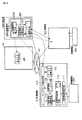
電力系統監視制御システムは、変電所、発電所等の電力系統関連施設が備える例えばインターネット等のネットワーク27に接続可能な管理装置15、20、25、30と、これらの管理装置15、20、25、30内の記憶データの記憶場所であるアドレス情報を管理、記憶している管理サーバ10とから構成される。
The power system monitoring and control system includes
管理装置15、20、25、30は、電力系統関連施設に関する情報を系統情報として記憶する記憶手段235と、所定のアプリケーション23Bであるサービス利用手段232および情報交換手段231と、記憶手段に記憶した記憶データの記憶場所の情報をアドレス情報として管理サーバ10に送信するネットワーク通信手段233とを備えている。情報交換手段231は、管理サーバ10から受信したアドレス情報に基づいて、当該アドレス情報に対応する記憶データをネットワーク27を介して受信し、受信した受信データを所定の形式に変換する。
The
管理サーバ10は、管理装置15、20、25、30から送信されたアドレス情報を受信し、記憶する記憶手段238と、ネットワーク27を介して、例えば管理装置15からアドレス情報の送信を促すリクエスト情報を受信した場合は、リクエスト情報に対応する記憶手段238に記憶されている受信したリクエスト情報に対応したアドレス情報を読み出す処理等を行うサービス管理手段221と、読み出したアドレス情報をリクエスト情報を送信した管理装置15を送信するネットワーク通信手段223とを備えている。
The
なお、管理サーバ10の記憶手段238には、サービス管理手段10により、登録されているアドレス情報(サービス)がリスト化されており、各サービスは、例えば、
装置名: URL(http://IPアドレス:ポート番号/ディレクトリ):サービス名
というように管理されている。サービス管理手段10は、記憶手段238に記憶されたアドレス情報名(サービス名)をキーとして記憶されたデータベースから検索を行ない、検索結果となる装置名やURLを抽出する。
The storage means 238 of the
Device name: URL (http: // IP address: port number / directory): Managed as service name. The service management means 10 performs a search from a database stored using the address information name (service name) stored in the storage means 238 as a key, and extracts a device name or URL as a search result.
以上のように構成された電力系統監視制御システムを適用した電力系統監視制御方法およびプログラムについて、図2を参照して説明する。 A power system monitoring control method and program to which the power system monitoring control system configured as described above is applied will be described with reference to FIG.
管理装置15は、ステップ1で、アプリケーション23Bおよび電力系統関連施設に関する情報を系統情報として記憶手段235に記憶する。管理装置15は、ステップS3で、記憶手段235に記憶した系統情報の記憶場所の情報をアドレス情報として管理サーバ10に送信する。所定の系統情報を取得したい場合に、管理装置15は、管理サーバ10に管理サーバ10にリクエスト情報を送信する。リクエスト情報を受信した管理サーバ10は、ステップS7で、受信したリクエスト情報を記憶し、ステップS9で、リクエスト情報に対応する系統情報が記憶されている場所の情報であるアドレス情報を検索し、管理装置15に送信する。管理装置15は、ステップS5で、管理サーバ10から受信したアドレス情報に基づいて、アドレス情報に対応する系統情報が記憶されている管理装置にアクセスし、ネットワーク27を介して所定の系統情報を受信し、受信した系統情報を所定の形式、例えばXMLに変換する。
In step 1, the
以下に図1および図2等を参照して、さらに詳しく説明を行う。 Hereinafter, a more detailed description will be given with reference to FIGS.
管理装置15から管理サーバ10へのアドレス情報の問い合わせの結果、必要な系統情報が管理装置25にあることとなると、管理装置25のサービス定義手段118からサービスを受ける(系統情報を受信する)ための手続きのプロトコルの授受を行う。アプリケーションであるサービス利用手段232は、この手続きに沿って、管理装置25のサービス手段114から系統情報や機能を取得する。この場合の機能とは、データ以外のプログラム等であり、具体的に言うと「エージェント」や「Java(登録商標)アプレット」等である。これらのプログラムなどをコード化してXMLに埋め込んで送受信し、使用者が復元して使うことが可能である。なお、上述したアプリケーションは、例えば、送電線の電流、電圧の値をもとに事故点を標定する送電線事故点標定アプリケーションやセンサーのオンオフ値をもとに警報を検出・発報するような機器監視アプリケーション等を用いる。
As a result of the inquiry of the address information from the
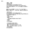
また、取得した系統情報に対してカスタマイズが必要な場合は、情報交換手段231において系統情報の変換や処理を行なう。例えば、変換や処理の具体例としては、図3に示すように、処理前のタグ等が入ったデータサンプルである、I=電流 v=電圧を示した。変換するための定義ファイルサンプル(XSLT形式)を参照し、電流(A)と電圧(V)より、電力P(W)、抵抗R(Ω)を算出する。
When the acquired system information needs to be customized, the
そして、サービス利用手段232は、変換された系統情報を利用する。例えば、サービス利用手段232は、情報交換手段231において変換された情報(図6では、電力と抵抗)を利用する。利用方法は、例えばXMLファイルをHTMLファイルに変換した後にWebブラウザで電力値と抵抗値を表示する、または、周期的に装置から取得する電力値、抵抗値をデータベースに記憶する、さらに、予め電力の上限値をデータベースに設定しておき取得した電力値がその上限値を越えていたら警報を出す(警報ランプ点灯や警報メール送信など)、等の処理が挙げられる。
Then, the
さらに、管理装置15で取得した系統情報を他の管理装置で利用することも可能である。管理装置15のサービス利用手段232が利用した情報や機能を、さらに図示しないサービス手段を追加して備えることにより、管理することができる。また、この場合、相互にどんなフォーマットの情報をやりとりするかを定義するサービス定義手段をも備える。なお、管理装置15でサービスを提供するためには、管理装置15に記憶されている系統情報のアドレス情報をサービス管理手段221に登録することが必要である。
Furthermore, the system information acquired by the
管理装置20(管理装置15と同様の構成)のアプリケーションである図示しないサービス利用手段は、必要な系統情報を持つ管理装置の有無をサービス管理手段221に対して問い合わせを行なう(必要な系統情報に対応するアドレス情報が記憶されているか検索する)。この場合ネットワーク越しの要求になるので、ネットワーク通信手段233を介して問い合わせ処理を行なう。問い合わせの結果、必要な系統情報が管理装置15にあることを確認すると、管理装置15からサービスを受けるための手続きを取得する。
Service utilization means (not shown), which is an application of the management apparatus 20 (same configuration as the management apparatus 15), inquires of the service management means 221 whether there is a management apparatus having the necessary system information (the necessary system information is included). Search for corresponding address information). In this case, since the request is made over the network, an inquiry process is performed via the network communication means 233. As a result of the inquiry, if it is confirmed that the necessary system information exists in the
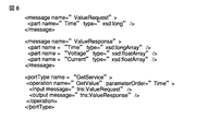
サービス定義手段は、相互にどんなフォーマットの情報をやりとりするか(サービスを提供するための手続き)を定義している。これはWSDL(Web Services Description Language)に相当する。 The service definition means defines what format information is exchanged with each other (procedure for providing a service). This corresponds to WSDL (Web Services Description Language).
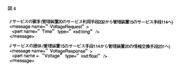
手続きの定義内容としては、例えば、ある時間の電圧が欲しいとリクエストすると、電圧の値がレスポンスされるサービスの手続きを図4に示すように定義している。 As the definition contents of the procedure, for example, a service procedure in which a voltage value is responded when a request for a voltage for a certain time is requested is defined as shown in FIG.
このような定義内容を記載した定義情報をサービス利用手段232からサービス定義手段118へ取得要求する。具体的には管理装置15のURLにフラグを付加してリクエストすると定義ファイルが返信される。
The
管理装置20のサービス利用手段232は、この手続きに沿って、管理装置15のサービス手段114から系統情報や機能を取得する。この場合、ネットワーク27越しの要求になるので、ネットワーク通信手段233を介して問い合わせ処理を行なう。取得した情報に対してカスタマイズが必要な場合は、情報交換手段231において取得した系統情報の変換や処理を行なう。サービス利用手段232ではその情報を利用する。
The service utilization means 232 of the
なお、ネットワーク27を介した管理装置間だけでなく、同じ管理装置内であっても、同様の手続きで上述した処理は実現することができる。
Note that the processing described above can be realized by the same procedure not only between management devices via the
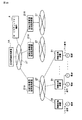
次に、電力系統監視制御システムをさらに具体的に図5を参照して説明する。 Next, the power system monitoring control system will be described more specifically with reference to FIG.
管理サーバ10は、図1と同様の構成となっており、管理装置23は、設備管理機能21の中に電力系統関連施設に関する情報を系統情報として記憶する系統情報記憶手段21aと、アプリケーション23Bである系統情報利用手段232aおよび系統情報交換手段231aと、記憶した系統情報の記憶場所の情報をアドレス情報として管理サーバ10に送信するネットワーク通信手段233とを備えている。
The
また、計測機器11の系統情報取得手段111は、周期的に電力系統設備11−1の系統情報(電力系統設備の各装置から取得した電流・電圧などの情報。カレント情報(現在値))を取得し、取得した時点の時刻情報と共に系統情報記憶手段112に系統情報を記憶する。系統情報記憶手段112では、蓄積情報(系統情報を保存して蓄積した系統情報を蓄積情報とする。)として系統情報、時刻(系統情報を取得した時の時刻)を取得した時点の時刻情報と共に記憶する。逐次的なデータ保存(系統情報の記憶)でデータ容量が増える場合は、保存容量を予め設定してサイクリックに一定期間データを記憶する手段も実施可能である。
Moreover, the system information acquisition means 111 of the measuring
系統情報を必要とするアプリケーション23Bとしては、例えば、送電線の電流、電圧の値をもとに事故点を標定する送電線事故点標定アプリケーションなどが挙げられる。
Examples of the
また、電力系統設備11−1に設置されている計測機器11の情報等の機器ID(図6参照)として、例えば、計測機器の識別情報を設定し、識別子を設備管理機能21の記憶領域21aに登録しておく。系統情報利用手段232は、この識別子を設備管理機能21の記憶領域21aから取得する。
Further, as the device ID (see FIG. 6) such as information on the measuring
管理サーバ10のサービス管理手段221より計測機器11、計測機器11のネットワークアドレスやサービス内容(計測機器11の系統情報サービス手段114で何を提供するかを定めた内容。「系統情報、時刻情報を提供するサービス」であり、「電流」、「電圧」等に該当する)を取得する。計測機器11が系統情報、時刻情報を提供するものであれば、サービス定義手段118よりサービスされる情報の受信フォーマットを確認する。例えば、図5のようなフォーマットを用いる。
From the service management means 221 of the
系統情報利用手段232は、ネットワーク通信手段233を介して計測機器11に要求(リクエスト情報)を送信し、リクエスト情報に対応する系統情報を受信する(サービスを受ける)。サービスを要求された計測機器11は、ネットワーク通信手段115で受信したリクエスト情報に基づき系統情報検索手段113により情報の検索を行い、系統情報記憶手段112から必要な系統情報を取得する。この系統情報はリクエストされた時刻近傍で記憶、保存されている一定期間の系統情報に時刻情報を付与したものである。取得した系統情報は、系統情報サービス手段114によりサービスを提供するフォーマットに変換される。例えば、インタフェース言語としてXML等を用いる。この時のフォーマットは、サービス定義手段118で定義されているフォーマットと同じものとなる。ネットワーク通信手段115を介して送信された系統情報は、サービスとしてアプリケーション23Bのネットワーク通信手段233に送信される。
The system
そして、ネットワーク通信手段233を介して系統情報を受信した系統情報交換手段231は、系統情報利用手段232の利用形態に合わせて系統情報を変換する。系統情報利用手段232は、変換された系統情報を用いてアプリケーションを実行する。例えば、取得した電流や電圧値などの系統情報を事故点標定のために電力P(W)や抵抗R(Ω)という利用形態に合わせて算出(変換)した上で、抵抗値やアプリが持っている送電線情報を使って事故点を標定する、等である(図7を用いて後述する)。
Then, the system
また、管理サーバ10のサービス管理手段221には、第3者によって計測機器11の系統情報を利用できる権限(系統情報にアクセス可能なアクセス権)が設定される。図6に示すように、設定内容2211は、計算機のIPアドレスであったり、利用するユーザ名であったり、セキュリティ上認証確認として有効な情報となる。また、計測機器11がサービスを提供できる状態にあるかないかによって、登録内容の1つである情報提供の可否設定を変える。情報適用の可否設定としては、該当サービスが利用できるかできないかの設定である。例えば、普段は情報を提供していないが、機器内で異常があったときのみ「警報提供サービス」を提供可能にする等。この場合、普段は「提供可否」が“否”で、異常時のみ“可”として再登録する。
In the
また、系統情報を必要とするアプリケーション23の系統情報利用手段232は、該当する電力系統設備に設置されている計測機器の機器情報(識別子)を記憶手段21より取得する。アプリケーション23Bは、サービス管理手段221に対して該当計測機器11として計測機器11へのアクセス可否情報(どの計算機がサービスを利用できるかといった情報提供の可否の情報)を要求する。サービス管理手段221では、要求したアプリケーションが稼動している計算機のIPアドレスをチェックし、それぞれの計測機器の系統情報を提供可能であれば、該当計測機器のネットワークアドレスやサービス内容などのアクセス可否情報を送信する。
Further, the system
なお、上述したアクセス権を用いて利用可能者を区分化することにより、電力系統における管轄範囲の概念などを取り込むことができる。 In addition, the concept of the jurisdiction range in an electric power system, etc. can be taken in by classifying an available user using the access right mentioned above.
また、アプリケーション23Bは、管理サーバ10から受信して記憶手段238に記憶しているアドレス情報をもとに計測機器11に対して系統情報を要求する。サービスを要求された計測機器11は、ネットワーク通信手段115で受信した要求に基づき系統情報検索手段113により系統情報記憶手段112から必要な系統情報を取得する。必要な系統情報は、要求された時刻における系統情報である。取得した系統情報は、系統情報サービス手段114によりサービスを提供するフォーマットである例えば、XML等に変換する。この時のフォーマットはサービス定義手段118で定義されているフォーマットと同じものである。ネットワーク通信手段115を介して送信された系統情報は、サービスとしてアプリケーション23Bのネットワーク通信手段233に提供される。
The
また、計測機器11で周期的に系統情報を取得しており、警報監視アプリケーション(図9を用いて後述する)は、計測機器11にサービスを要求する。計測機器11の系統情報の値が変化した時にその警報監視アプリケーションのネットワーク通信手段に対してその時刻での系統情報を送信する。以降、継続的に系統情報の変化を検出し、系統情報を送信する。
Moreover, the system information is periodically acquired by the measuring
次に、図7を用いて、送電線事故点標定を行なう電力系統サービスシステムについて詳しく説明する。 Next, a power system service system that performs power transmission line fault location will be described in detail with reference to FIG.
送電線11−2の両端には送電線の電流、電圧などの系統情報を取り込む計測機器11が設置されている。計測機器11は、図5と同様の構成となっている。なお、ネットワーク通信手段等の表示を省略している箇所等もある。また、図5の系統情報利用手段232aは、事故点標定手段232bに相当し、管理装置23は、工務所(の管理装置)501に相当する。
At both ends of the power transmission line 11-2, a measuring
工務所501は、管轄する送電線11−2、計測機器11、管理サーバ10にネットワーク27を介して接続可能である。
The construction office 501 can be connected to the power transmission line 11-2, the measuring
計測機器11の系統情報取得手段111は、周期的に系統情報である送電線の電圧、電流を取得し、取得した時点の時刻情報と共に系統情報記憶手段112に電流、電圧値を記憶する。系統情報記憶手段112は、これらの系統情報を順次蓄積し、蓄積情報として電流値、電圧値、時刻情報を記憶する。また、逐次的なデータ保存でデータ容量が増える場合は保存容量を予め設定してサイクリックに一定期間データを記憶する手段も実施可能である。
The system
そして、送電線11−2にて事故の発生を検出すると、送電線事故点標定アプリケーション23Cの事故点標定手段232bは、該当送電線11−2に設置されている計測機器11の機器情報(識別子)を記憶手段21から取得する。管理サーバ10のサービス管理手段221から該当計測機器11として計測機器11のネットワークアドレスやサービス内容を取得する。該当計測機器11が電流、電圧、時刻情報を提供するサービスを行っていれば、サービスされる系統情報等の情報の受信フォーマットを確認する。なお、サービス定義手段における定義は、例えば、図8に示すようになる。
When the occurrence of an accident is detected in the power transmission line 11-2, the accident point locating means 232b of the power transmission line accident locating application 23C detects the device information (identifier) of the measuring
事故点標定手段232bは、ネットワーク通信手段233を介して計測機器11から系統情報等の情報を受信する(サービスを受ける)。サービスを要求された計測機器11は、ネットワーク通信手段115で受信した要求に基づき系統情報検索手段113により系統情報記憶手段112から必要な系統情報を取得する。この際に、要求するフォーマットとしては、例えば、図9に示すように、事故の発生した時刻を設定する。
The accident point location unit 232b receives information such as system information from the measuring
また、必要な系統情報は事故発生時近傍で記憶されている一定期間の電圧、電流に時刻情報を付与したものである。取得した系統情報は、系統情報サービス手段114によりサービスを提供するフォーマットに変換される。インタフェース言語としてXMLなどを利用する。この際に、送信されるフォーマットは、例えば、図10に示すように、事故が発生した前後10秒間に蓄積されている電圧と電流が設定される。 Necessary system information is obtained by adding time information to voltage and current for a certain period stored in the vicinity of the occurrence of the accident. The acquired system information is converted into a format for providing a service by the system information service means 114. XML or the like is used as an interface language. At this time, as the format to be transmitted, for example, as shown in FIG. 10, the voltage and current accumulated for 10 seconds before and after the accident occurs are set.
この時フォーマットはサービス定義手段118で定義されているフォーマットと一致する。ネットワーク通信手段115を介して送信された系統情報は、サービスとして送電線事故点標定アプリケーション23Cのネットワーク通信手段233に送信、提供される。
At this time, the format matches the format defined by the service definition means 118. The system information transmitted via the
系統情報交換手段231は、瞬時値や実効値変換などを実施し、さらにインピーダンスへの変換など、事故点標定手段232bの利用形態に合わせて系統情報を変換する。この際の変換定義は、例えば、図11に示すようになる。これにより事故前後10秒間の送電線インピーダンスを得ることができる。また、事故点標定手段232bは変換された系統情報を用いて事故点を標定する。事故時の送電線のインピーダンスから送電線において短絡などが落ちた地点を標定する。
The system
以上、本発明の実施形態によれば、事故点標定に必要な系統情報を常にアプリケーション側で保持する必要がなく、系統情報を必要としたときに計測機器よりサービスを受ければよいため、ネットワーク構成の変動に対する柔軟性が確保できると共に工務所以外の事業所においても該当系統情報を取得することが可能となり、アプリケーションを利用できる範囲(制御所運転員から工務担当、行政など)が広がる。また通信負荷の軽減も実現できる。 As described above, according to the embodiment of the present invention, it is not necessary to always hold the system information necessary for the accident location on the application side, and it is sufficient to receive a service from the measuring device when the system information is required. It is possible to secure flexibility with respect to fluctuations in the system, and it is also possible to acquire relevant system information at business establishments other than the construction office, and the range in which the application can be used (from control station operators to construction staff, administration, etc.) is expanded. In addition, the communication load can be reduced.
(第2実施形態)
第2実施形態では、発電電力量と受電電力量の同時同量制御を行なう電力系統サービスシステムについて図12を参照して説明する。なお、以下、すべての実施形態では、同様のものには同符号で示し、詳しい説明を省略する。
(Second Embodiment)
In the second embodiment, a power system service system that performs the same amount control of the generated power amount and the received power amount will be described with reference to FIG. Hereinafter, in all the embodiments, the same components are denoted by the same reference numerals, and detailed description thereof is omitted.
第2実施形態の構成は、図5の構成と同様であり、管理装置を備えた電気の小売事業者が追加されている。また、電気の需要家507および発電事業者503は、それぞれ計測機器11、12および電力用パルスを備えている。なお、本実施形態で用いるタグデータ等は、上述した第1実施形態において示したタグデータで置き換えたフォーマットを適用するものとする。
The configuration of the second embodiment is the same as the configuration of FIG. 5, and an electrical retailer equipped with a management device is added. Moreover, the electric consumer 507 and the electric power generation company 503 are each provided with the measuring
電気の需要家507は、受電設備として取引用電力計から受電電力量などの系統情報を取り込む計測機器11を備えている。計測機器11は、系統情報取得手段111、系統情報記憶手段112、サービスする系統情報を抽出する系統情報検索手段113、サービスする系統情報を伝送用にXML形式に変換する系統情報サービス手段114、および系統情報を外部に伝送するネットワーク通信手段115を備えており、系統情報をイントラネット・インターネットを介して提供するサービスを行う。
The electricity consumer 507 includes a measuring
発電事業者503は、発電設備として取引用電力計から発電電力量などの系統情報を
取り込む計測機器12を備えている。計測機器12は、系統情報取得手段121、系統情報記憶手段122、サービスする系統情報を抽出する系統情報検索手段123、サービスする系統情報を伝送用にXML形式に変換する系統情報サービス手段124、および系統情報を外部に伝送するネットワーク通信手段125を備えており、系統情報をイントラネット・インターネットを介して提供するサービスを行う。また、計測機器12が電力量を提供できること及びインタフェースの内容を定義したサービス定義手段118を備えている。
The power generation company 503 includes a measuring
小売事業者505は、需給制御の対象となる発電事業者情報、需要家の契約関係情報、受発電量情報などを記憶する記憶手段21、発電事業者503、需要家507に備えられている計測機器11、12からの系統情報をもとに需給制御する同時同量制御手段232cをもつ同時同量制御アプリケーション23Dを有している。
The retailer 505 includes a
計測機器11の系統情報取得手段111は、周期的に取引用電力計から電力用パルスを取得し、取得した時点の時刻情報と共に系統情報記憶手段112にパルス値を記憶する。この時点でパルス値に重み付けを行ない電力量に変換して渡すことも可能である。系統情報記憶手段112は、これらの情報を蓄積し、蓄積情報としてパルス値、時刻情報を記憶する。逐次的なデータ保存でデータ容量が増える場合は保存容量を予め設定してサイクリックに一定期間データを記憶する手段も実施可能である。なお、計測機器12も計測機器11の作用となる。
The system
同時同量制御アプリケーション23Dの同時同量制御手段232cは、記憶手段21から発電元の発電事業者503と受電先の需要家507の対応関係情報及び契約量情報を取得する。サービス管理手段221より需要家507の計測機器11と発電事業者503の計測機器12のネットワークアドレスや系統情報を提供するサービス内容を取得する。該当計測機器11、12がパルス量情報(または電力量情報)、時刻情報を提供するサービスをもっていれば、サービス定義手段118から提供(サービス)される情報の受信フォーマットを確認する。ここではパルス量情報が提供されるとする。同時同量制御手段232cは、ネットワーク通信手段233を介して計測機器11、計測機器12から系統情報を受信する(サービスを受ける)。
The simultaneous and same amount control means 232c of the simultaneous and same amount control application 23D acquires correspondence information and contract amount information between the power generation company 503 of the power generation source and the customer 507 of the power receiving destination from the storage means 21. The
サービス管理手段221に対して、情報提供先を限定するため、計測機器11、12の機器情報を登録する際に、パスワードを設定する。サービスの利用者がサービス管理手段221より需要家507の計測機器11と発電事業者503の計測機器のネットワークアドレスや系統情報を提供するサービス内容を取得する際に指定したパスワードが許可する計測機器の機器情報のみが取得可能となる。
In order to limit the information providing destination to the service management means 221, a password is set when registering the device information of the measuring
サービスを要求された計測機器11は、ネットワーク通信手段115で受信した要求に基づき系統情報検索手段113により系統情報記憶手段112から必要な系統情報を取得する。必要な系統情報は定周期で保存されている一定期間のパルス量に時刻情報を付与したものである。取得した系統情報は、系統情報サービス手段114によりサービスを提供するフォーマットに変換される。インタフェース言語としてXMLなどを利用する。この時フォーマットはサービス定義手段118で定義されているフォーマットと一致する。ネットワーク通信手段115を介して送信された系統情報は、サービスとして同時同量制御アプリケーション23Dのネットワーク通信手段233に提供される。サービスを要求された計測機器12は計測機器11と同様の作用となる。
The measuring
系統情報交換手段231は、パルス値の電力量値変換などを実施し、同時同量制御手段232cの利用形態に合わせて系統情報を変換する。同時同量制御手段232cは、この系統情報を用いて受電電力量と発電電力量の監視を行ない、発電制御の指令を出し、制御を行う。
The system
本実施形態によれば、取引電力量を検出する計測機器11が提供する系統情報がパルス値であるか電力量であるかを問わず計測機器へのサービス要求時に系統情報の受信フォーマットを決定できるため、取得する系統情報の形式に依らずアプリケーションの構築が行なえる。また、インターネット上に接続された機器であっても使用権限を与えることによりセキュリティを確保できる。
According to the present embodiment, it is possible to determine the reception format of the system information when a service request is made to the measuring device regardless of whether the system information provided by the measuring
(第3実施形態)
第3実施形態では、電源盤などに設置された警報ランプなどの電気設備監視を行なう電力系統サービスシステムについて、図13を参照して説明する。
(Third embodiment)
In the third embodiment, a power system service system that monitors electrical equipment such as alarm lamps installed on a power panel or the like will be described with reference to FIG.
本発明に係る第3実施形態の電気設備監視を行なう電力系統サービスシステムの構成としては、図5とほぼ同様である。警報監視アプリケーション23Eを備えたビル管理室511、故障検出アプリケーション33を備えたメンテナンス会社509、電源盤513、512の警告ランプ1、2、3、4の光を光センサーで感知し、系統情報として取得する計測機器11、12とから構成される。
The configuration of the power system service system that performs electrical facility monitoring according to the third embodiment of the present invention is substantially the same as that shown in FIG. The building management room 511 provided with the alarm monitoring application 23E, the maintenance company 509 provided with the failure detection application 33, and the light of the
ビルや工場などの電気設備である電源盤などに備え付けられている警報ランプ1、2、3、4の点灯状態などの系統情報を取り込む計測機器11が設置されている。計測機器11は、図5と同様の構成に加え、系統情報取得手段111は、電源盤513に備えられた警告ランプ1〜3の光を感知する光センサーからの信号を系統情報として取得する。また、系統情報検索手段113は、系統情報を抽出し、系統情報サービス手段114は、サービスする系統情報を伝送用にXML形式に変換する。サービス定義手段118は、計測機器11が電力量を提供できるか否かの情報及びインタフェースの内容情報を定義した定義情報を備える。
A measuring
また、電気設備を監視する場所、例えばビル管理室511の警報監視アプリケーション23Eは、計測機器11と情報交換を行なうネットワーク通信手段233、監視対象である電源盤513に設置されている計測機器11の光センサーから取得した系統情報を統合、変換する系統情報交換手段231、系統情報をもとに警報を検出する警報監視手段232を備えている。
In addition, the alarm monitoring application 23E in the place where the electrical equipment is monitored, for example, the building management room 511, the network communication means 233 for exchanging information with the measuring
また、電気設備のメンテナンスを行なう会社メンテナンス会社509の故障検出アプリケーション33は、計測機器11と情報交換を行なうネットワーク通信手段333、監視する電源盤513に設置されている計測機器11の光センサーから取得した系統情報を統合、変換する系統情報交換手段331、系統情報をもとに故障判定を行なう故障判定手段332を備えている。
Further, the failure detection application 33 of the company maintenance company 509 that performs maintenance of the electrical equipment is acquired from the optical sensor of the measuring
以上のように構成された本発明の第3実施形態に係る電力系統サービスシステムの処理について説明する。 Processing of the power system service system according to the third embodiment of the present invention configured as described above will be described.
計測機器11の系統情報取得手段111は、周期的に電源盤513に設置された警報ランプ1〜4の点灯状態(点灯/消灯、色など)を光センサーによりディジタル化した警報情報(系統情報)を取得し、状態が変化した時の変化後状態値とその時点の時刻情報を系統情報記憶手段112に記憶する。系統情報記憶手段112は、これらの記憶された系統情報を蓄積情報として状態値、時刻情報を記憶する。この時、保存容量を予め設定してサイクリックに一定期間データを記憶する手段も実施可能である。
The system information acquisition means 111 of the measuring
警報監視アプリケーション23Eの警報監視手段232dは、計測機器11から計測機器11のネットワークアドレスや系統情報を提供するサービス内容情報及び設置場所情報を取得する。該当計測機器11が警報ランプ状態情報、時刻情報を提供するサービスをもっていれば、サービス定義手段118よりサービスされる情報の受信フォーマットを確認する。警報監視アプリケーション23Eが監視対象としている計測機器11に対してネットワーク通信手段233を通して計測機器11などより系統情報を受信する(サービスを受ける)。
The
サービスを要求された計測機器11は、ネットワーク通信手段115で受信した要求に基づき系統情報検索手段113により系統情報記憶手段112から必要な系統情報を取得する。必要な系統情報は、要求時間内に保存した状態値に時刻情報を付与したものである。取得した系統情報は、系統情報サービス手段114によりサービスを提供するフォーマットに変換される。インタフェース言語としてXMLなどを利用する。この時フォーマットはサービス定義手段118で定義されているフォーマットと一致する。ネットワーク通信手段115を介して送信された系統情報は、サービスとして警報監視アプリケーション23Eのネットワーク通信手段233に提供される。
The measuring
系統情報交換手段231は、警報監視手段232の利用形態に合わせて系統情報を変換する。警報監視手段232は、変換後の系統情報を用いて警報ランプの監視を行なう。
The system
メンテナンス会社509における故障検出アプリケーション33の故障判定手段332は、管理サーバ10のサービス管理手段221より計測機器11のネットワークアドレスや系統情報を提供するサービス内容情報及び設置場所情報を取得する。該当計測機器11が警報ランプ状態情報、時刻情報を提供するサービスをもっていれば、サービス定義手段118よりサービスされる情報の受信フォーマットを確認する。故障検出アプリケーション33が監視対象としている計測機器11に対してネットワーク通信手段333を通して計測機器11などより系統情報を受信する(サービスを受ける)。
The
サービスを要求された計測機器11は、ネットワーク通信手段115で受信した要求に基づき系統情報検索手段113により系統情報記憶手段112から必要な系統情報を取得する。必要な系統情報は、要求時間内に保存した状態値に時刻情報を付与したものである。取得した系統情報は、系統情報サービス手段114によりサービスを提供するフォーマットに変換される。インタフェース言語としてXMLなどを利用する。この時フォーマットはサービス定義手段118で定義されているフォーマットと一致する。ネットワーク通信手段115を介して送信された系統情報は、サービスとして故障検出アプリケーション33のネットワーク通信手段333に提供される。
The measuring
系統情報交換手段331は、故障判定手段332が対象としている警報ランプの状態のみを抽出し、その利用形態に合わせて系統情報を変換する。故障判定手段332は、変換された系統情報を用いて、予め設定してある判定条件に照らし合わせて電源盤513内の故障検出を行なう。
The system
以上、第3実施形態によれば、電源盤に設置された警報ランプの表示状態を提供するサービスを利用することにより、警報監視アプリケーションと故障検出アプリケーションという異なるアプリケーションからの情報アクセスが統一したインタフェースで実現可能となる。 As described above, according to the third embodiment, by using a service that provides a display state of an alarm lamp installed on a power supply panel, an information access from different applications, that is, an alarm monitoring application and a failure detection application, is unified. It becomes feasible.
また、第3実施形態の変形例として、電源盤などに設置された警報ランプなどの電気設備監視を行なう電力系統サービスシステムについて説明する。なお、構成は第3実施形態と同等である。 As a modification of the third embodiment, a power system service system that monitors electrical equipment such as alarm lamps installed on a power panel or the like will be described. The configuration is the same as that of the third embodiment.
上述した第3実施形態と同様に、計測機器11で取得した系統情報は、警報監視アプリケーション23Eで利用される。特に計測機器11では、次に示す作用となる。
Similarly to the third embodiment described above, the system information acquired by the measuring
サービスを要求された計測機器11は、ネットワーク通信手段115で受信した要求に基づき系統情報検索手段113により系統情報記憶手段112から必要な系統情報を取得する。必要な系統情報は、要求時間内に保存した状態値に時刻情報を付与したものである。取得した系統情報は、系統情報サービス手段114によりサービスを提供するフォーマットに変換される。インタフェース言語としてXMLなどを利用する。この時フォーマットはサービス定義手段118で定義されているフォーマットと一致する。ネットワーク通信手段115を介して送信された系統情報は、サービスとして警報監視アプリケーション23Eのネットワーク通信手段233に提供される。サービスを要求した警報監視アプリケーション23Eのネットワーク通信手段233に対して以降は状態変化を検出した際に上記作用を行なう。
The measuring
以上、第3実施形態の変形例によれば、電源盤に設置された警報ランプの表示状態を提供する1つのサービスを利用することにより、警報監視と故障検出という異なるアプリケーションがともに統一したインタフェースを用いてアプリケーションを構築することが可能となる。 As described above, according to the modification of the third embodiment, by using one service that provides a display state of an alarm lamp installed on the power panel, an interface in which different applications of alarm monitoring and failure detection are unified is provided. It is possible to construct an application by using it.
(第4実施形態)
第4実施形態では、電源盤などより得られる電流・電圧などの電力情報を使ったエネルギー監視・解析を行なう電力系統サービスシステムについて、図14を参照して説明する。
(Fourth embodiment)
In the fourth embodiment, a power system service system that performs energy monitoring / analysis using power information such as current / voltage obtained from a power panel or the like will be described with reference to FIG.
本発明に係る第4実施形態の電気設備監視を行なう電力系統サービスシステムは、保安会社517、管理サーバ10、ビル管理室519、監視対象の電源盤521から系統情報を取得する計測機器11とから構成される。
The power system service system that performs electrical facility monitoring according to the fourth embodiment of the present invention includes a security company 517, a
計測機器11は、ビルや工場などの電気設備である電源盤521などから電流・電圧などの電気量を系統情報として取り込む系統情報取得手段111、取り込んだ系統情報を記憶する系統情報記憶手段112、サービスする系統情報を抽出する系統情報検索手段113、サービスする系統情報を伝送用にXML形式に変換する系統情報サービス手段114、系統情報を外部に伝送するネットワーク通信手段115、計測機器11が電力量を提供できること及びインタフェースの内容を定義したサービス定義手段118を備える。
The measuring
また、電気設備を監視する場所、例えばビル管理室519は、計測機器11と情報交換を行なうネットワーク通信手段233、監視する電源盤に設置されている計測機器11から取得した系統情報を統合、変換する系統情報交換手段231、系統情報をもとに警報を検出する電力監視手段232eを有する電力監視アプリケーション23Fを備える。また、管理サーバ10は、サービス管理手段221を備える。
In addition, the location where the electrical equipment is monitored, for example, the building management room 519, integrates and converts the system information acquired from the network communication means 233 for exchanging information with the measuring
電気設備の保安業務を担う保安会社517は、計測機器11と情報交換を行なうネットワーク通信手段333、監視する電源盤521に設置されている計測機器11から取得した系統情報を統合、変換する系統情報交換手段331、系統情報をもとにエネルギー解析を行なうデータ解析手段332を有する電力解析アプリケーション33Aを備える。
The security company 517 responsible for the security operation of the electrical equipment integrates and converts the system information acquired from the network communication means 333 for exchanging information with the measuring
計測機器11の系統情報取得手段111は、周期的に電源盤521に設置された図示しない変成器(CT,VT)から電気量を系統情報として計測値を取得し、この計測値と取得した時の時刻を系統情報記憶手段112に記憶する。系統情報記憶手段112は、系統情報を蓄積し、蓄積情報として計測値、時刻情報を記憶する。この時、保存容量を予め設定してサイクリックに一定期間データを記憶する手段も実施可能である。
When the system information acquisition means 111 of the measuring
電力監視アプリケーション23Fの電力監視手段232eは、計測機器11のネットワークアドレスや系統情報を提供するサービス内容情報及び設置場所情報を取得する。電気量情報、時刻情報を提供するサービスをもっていれば、サービス定義手段118よりサービスされる情報の受信フォーマットを確認する。電力監視アプリケーション23Fが監視対象としている計測機器11に対してネットワーク通信手段233を介して計測機器11などより系統情報を受信する(サービスを受ける)。
The power monitoring unit 232e of the power monitoring application 23F acquires service content information and installation location information that provide the network address and system information of the measuring
サービスを要求された計測機器11は、ネットワーク通信手段115で受信した要求に基づき系統情報検索手段113により系統情報記憶手段112から必要な系統情報を取得する。必要な系統情報は、要求時間内に保存した状態値に時刻情報を付与したものである。取得した系統情報は、系統情報サービス手段114によりサービスを提供するフォーマットに変換される。インタフェース言語としてXMLなどを利用する。この時フォーマットはサービス定義手段118で定義されているフォーマットと一致する。ネットワーク通信手段115を介して送信された系統情報は、サービスとして警報監視アプリケーション23のネットワーク通信手段233に提供される。
The measuring
系統情報交換手段231は、電力監視手段232eの利用形態に合わせて系統情報を変換する。電力監視手段232eは、この系統情報を用いて電力設備の監視を行なう。
The system
電力解析アプリケーション33Aのデータ解析手段332は、計測機器11のネットワークアドレスや系統情報を提供するサービス内容情報及び設置場所情報を取得する。該当計測機器11が電気量情報、時刻情報を提供するサービスをもっていれば、サービス定義手段118よりサービスされる情報の受信フォーマットを確認する。電力解析アプリケーション33Aが解析対象としている計測機器11に対してネットワーク通信手段333を通して計測機器11などより系統情報を受信する(サービスを受ける)。
The data analysis means 332 of the power analysis application 33A acquires service content information and installation location information that provide the network address and system information of the measuring
サービスを要求された計測機器11は、ネットワーク通信手段115で受信した要求に基づき系統情報検索手段113により系統情報記憶手段112から必要な系統情報を取得する。必要な系統情報は、要求時間内に保存した状態値に時刻情報を付与したものである。取得した系統情報は、系統情報サービス手段114によりサービスを提供するフォーマットに変換される。インタフェース言語としてXMLなどを利用する。この時フォーマットはサービス定義手段118で定義されているフォーマットと一致する。ネットワーク通信手段115を介して送信された系統情報は、サービスとして系統解析アプリケーション33のネットワーク通信手段333に提供される。
The measuring
系統情報交換手段331は、データ解析手段332が対象としている電気量情報のみを抽出し、その利用形態に合わせて系統情報を変換する。データ解析手段332は、変換された系統情報を用いて電気量のオシロ情報やトレンド情報として運転員に提供する情報を生成したり、しきい値などの設定情報があれば設定値逸脱の期間、回数などの解析を行なう。
The system
以上、第4実施形態によれば、電源盤から取得できる系統情報を提供する1つのサービスを利用することにより、電力監視と電力解析という異なるアプリケーションがともに統一したインタフェースを用いてアプリケーションを構築することが可能となる。また、解析手法においても統一的な情報が取得できるためユーザが必要とする解析ツールに応じた解析が行なえるようになる。 As described above, according to the fourth embodiment, by using one service that provides system information that can be acquired from the power panel, an application is constructed using an interface in which different applications of power monitoring and power analysis are unified. Is possible. Also, since unified information can be acquired in the analysis method, analysis according to the analysis tool required by the user can be performed.
(第5実施形態)
第5実施形態では、電源盤などより得られる電流・電圧などの電力情報を使ったエネルギー監視・解析を行なう電力系統サービスシステムであって、絶縁監視を行なう電力系統サービスシステムについて、図15を参照して説明する。
(Fifth embodiment)
In the fifth embodiment, a power system service system that performs energy monitoring / analysis using power information such as current and voltage obtained from a power supply panel, etc., for a power system service system that performs insulation monitoring, see FIG. To explain.
本発明に係る第5実施形態の電気設備監視を行なう電力系統サービスシステムは、ビルや工場
・変電所などに設置される図示しない変圧器の漏れ電流を取り込む計測機器11が設置されている。
The power system service system for monitoring electrical facilities according to the fifth embodiment of the present invention is provided with a measuring
計測機器11は、系統情報取得手段111と系統情報保存手段112、サービスする系統情報を抽出する系統情報検索手段113、サービスする系統情報を伝送用にXML形式に変換する系統情報サービス手段114、系統情報を外部に伝送するネットワーク通信手段115、計測機器11が漏れ電流の情報を提供できること及びインタフェースの内容を定義したサービス定義手段118を備える。
The measuring
変電設備を監視する場所、例えば運転室523は、計測機器11と情報交換を行なうネットワーク通信手段233、監視する電源盤525に設置されている計測機器11から取得した系統情報を統合、変換する系統情報交換手段231、変換された系統情報をもとに絶縁状態を判定する絶縁解析手段232fを有する絶縁監視アプリケーション23GGを備える。なお、設置場所により運転室以外の場合もある。管理サーバ10は、変電設備に設置されている計測機器11を管理し、計測機器11のネットワークアドレスとサービス内容を管理するサービス管理手段221を備える。
A place where the substation equipment is monitored, for example, the cab 523 is a
計測機器11の系統情報取得手段111は、周期的に変圧器に設置された図示しない変成器(CT)から漏れ電流の計測値を取得し、取得した計測値と取得した時の時刻を系統情報記憶手段112に記憶する。系統情報記憶手段112は、蓄積された系統情報を蓄積情報として計測値、時刻情報を記憶する。この時、保存容量を予め設定してサイクリックに一定期間データを保存する手段も実施可能である。
The system information acquisition means 111 of the measuring
絶縁監視アプリケーション23Gの絶縁解析手段232fは、計測機器11のネットワークアドレスや系統情報を提供するサービス内容情報及び設置場所情報を取得する。漏れ電流情報、時刻情報を提供するサービスをもっていれば、サービス定義手段118及びサービス定義手段128よりサービスされる情報の受信フォーマットを確認する。絶縁監視アプリケーション23Gが監視対象としている計測機器11に対してネットワーク通信手段233を介して計測機器11などより系統情報を受信する(サービスを受ける)。
The insulation analysis means 232f of the insulation monitoring application 23G acquires service content information and installation location information that provide the network address and system information of the measuring
サービスを要求された計測機器11は、ネットワーク通信手段115で受信した要求に基づき系統情報検索手段113により系統情報記憶手段112から必要な系統情報を取得する。必要な系統情報は、要求時間内に保存した状態値に時刻情報を付与したものである。取得した系統情報は、系統情報サービス手段114によりサービスを提供するフォーマットに変換される。インタフェース言語としてXMLなどを利用する。この時フォーマットはサービス定義手段118で定義されているフォーマットと一致する。ネットワーク通信手段115を介して送信された系統情報は、サービスとして絶縁監視アプリケーション23Gのネットワーク通信手段233に提供される。
The measuring
系統情報交換手段231は、絶縁解析手段232fの利用形態に合わせて系統情報を変換する。絶縁解析手段232fは、漏れ電流の状況により該当設備の絶縁状態を解析し、寿命予測などを行なう。
The system
以上、第5実施形態によれば、変電設備の設置場所が人的アクセスの難易に依らず、遠隔地から系統情報を取得することにより設備の寿命予測、運転監視が行なえる。 As described above, according to the fifth embodiment, the lifespan of the facility and the operation monitoring can be performed by acquiring the system information from a remote place, regardless of the difficulty of human access at the location where the substation equipment is installed.
(第6実施形態)
第6実施形態では、計測機器のパルスカウントによるデマンド監視を行なう電力系統サービスシステムについて、図16を参照して説明する。
(Sixth embodiment)
In the sixth embodiment, a power system service system that performs demand monitoring based on pulse counts of measuring devices will be described with reference to FIG.
本発明に係る第6実施形態の電力系統サービスシステムは、電気の需要家529、需要家529が有する計測機器11を管理する計測機器管理室527、および管理サーバ10とから構成される。
The power system service system according to the sixth embodiment of the present invention includes an electricity consumer 529, a measurement device management room 527 for managing the
需要家529は、受電設備から受電電力量などの系統情報を取り込む計測機器11が設置されている。計測機器11は、系統情報取得手段111、系統情報記憶手段112、サービスする系統情報を抽出する系統情報検索手段113、サービスする系統情報を伝送用にXML形式に変換する系統情報サービス手段114、系統情報を外部に伝送するネットワーク通信手段115、計測機器11が電力量情報を提供できること及びインタフェースの内容を定義したサービス定義手段118を備える。
The consumer 529 is provided with a measuring
計測機器管理室527は、計測機器11と情報交換を行なうネットワーク通信手段233、監視する計測機器11から取得した系統情報を統合、変換する系統情報交換手段231、変換された系統情報をもとに設備の系統情報異常を検出するデマンド監視手段232gを有するデマンド監視アプリケーション23H(設置場所により計測機器管理室527以外の場合もある)、電力用パルスが設置されている計測機器11を管理し、計測機器11のネットワークアドレスとサービス内容を管理するサービス管理手段221を備える。
The measuring device management room 527 integrates network information means 233 for exchanging information with the measuring
計測機器11の系統情報取得手段111は、周期的に受電設備から電力用パルスを取得し、取得した時点の時刻情報と共に系統情報記憶手段112にパルス値を記憶する。この時点でパルス値に重み付けを行ない電力量に変換して記憶ことも可能である。系統情報記憶手段112は、蓄積された系統情報を蓄積情報としてパルス値、時刻情報を記憶する。逐次的なデータ保存でデータ容量が増える場合は保存容量を予め設定してサイクリックに一定期間データを記憶する手段も実施可能である。
The system
デマンド監視アプリケーション23Hのデマンド監視手段232gは、管理サーバ10のサービス管理手段221より需要家529の計測機器11のネットワークアドレスや系統情報を提供するサービス内容情報を取得する。該当計測機器11がパルス量(または電力量)、時刻情報を提供するサービスをもっていれば、サービス定義手段118よりサービスされる情報の受信フォーマットを確認する。ここではパルス量が提供されるとものとする。デマンド監視手段232gは、ネットワーク通信手段233を介して計測機器11より系統情報を受信する(サービスを受ける)。
The
系統情報交換手段231は、パルス値の電力量値変換などを実施し、デマンド監視手段232gの利用形態に合わせて系統情報を変換する。デマンド監視手段232gは、変換された系統情報を用いて電力量の監視を行ない、電力デマンド監視を行なう。
The system
以上、第6実施形態によれば、電力量を検出する計測機器11が提供する系統情報をサービス検索するだけで容易に情報を取得できるため、ユーザニーズに合わせてアプリケーションを容易に作成できる。またそれぞれの計測機器間でも情報のやりとりができるのでシステム間の情報共有が容易となり、アプリケーションに柔軟な対応ができる。
As described above, according to the sixth embodiment, since information can be easily acquired simply by performing a service search on the system information provided by the measuring
(第7実施形態)
第7実施形態では、変圧器の温度や油圧などを監視する電力系統サービスシステムについて、図17を参照して説明する。
(Seventh embodiment)
In the seventh embodiment, a power system service system for monitoring the temperature, hydraulic pressure, etc. of a transformer will be described with reference to FIG.
本発明に係る第7実施形態の電力系統サービスシステムは、変電設備11a、12a、メンテナンス会社531、管理サーバ10、変電設備管理室533から構成されている。
The electric power system service system of 7th Embodiment which concerns on this invention is comprised from the transformation equipment 11a and 12a, the maintenance company 531, the
変電設備11aは、図示しない変圧器などに備え付けられている温度センサー535から系統情報を取り込む系統情報取得手段111、取り込んだ系統情報を記憶する系統情報記憶手段112、サービスする系統情報を抽出する系統情報検索手段113、サービスする系統情報を伝送用にXML形式に変換する系統情報サービス手段114、系統情報を外部に伝送するネットワーク通信手段115、変電設備の温度・油圧を提供できること及びインタフェースの内容を定義したサービス定義手段118を備える。
The substation equipment 11a includes a system
変電設備管理室533は、変電設備11a、12aと情報交換を行なうネットワーク通信手段233、監視する変電設備から取得した系統情報を統合、変換する系統情報交換手段231、変換された系統情報をもとに設備の系統情報異常を検出する設備監視手段232hを有する設備監視アプリケーション23I(設置場所により管理室以外の場合もある)を有している。また、管理サーバ10は、温度センサーや油圧センサーが設置されている変電設備を管理し、変電設備11a、12aのネットワークアドレスとサービス内容を管理するサービス管理手段221を有している。
The substation equipment management room 533 includes network communication means 233 for exchanging information with the substation equipment 11a and 12a, system
また、変電設備11a、12aのメンテナンスを行なうメンテナンス会社531は、変電設備11a、12aと情報交換を行なうネットワーク通信手段333、監視する変電設備から取得した系統情報を統合、変換する系統情報交換手段331、変換された系統情報をもとに故障判定を行なう故障判定手段332をもつ故障検出アプリケーション33Bを有している。
The maintenance company 531 that performs maintenance of the substations 11a and 12a includes a
変電設備11の系統情報取得手段111は、周期的に図示しない変圧器などに備え付けられている温度センサー535によりディジタル化した系統情報(温度、圧力)を取得し、状態が変化した時の変化後状態値とその時点の時刻を系統情報記憶手段112に記憶する。系統情報記憶手段112は、蓄積された系統情報を蓄積情報として状態値、時刻情報を記憶する。この時、保存容量を予め設定してサイクリックに一定期間データを記憶する手段も実施可能である。
The system information acquisition means 111 of the
設備監視アプリケーション23Iの設備監視手段232hは、管理サーバ10のサービス管理手段221より変電設備のネットワークアドレスや系統情報を提供するサービス内容情報及び設置場所情報を取得する。該当変電設備が温度情報、油圧情報、時刻情報を提供するサービスをもっていれば、サービス定義手段118及びサービス定義手段128よりサービスされる情報の受信フォーマットを確認する。設備監視アプリケーション23Iが監視対象としている変電設備に対してネットワーク通信手段233を介して変電設備11、変電設備12などより系統情報を受信する(サービスを受ける)。
The equipment monitoring means 232h of the equipment monitoring application 23I obtains service content information and installation location information that provide the network address and system information of the substation equipment from the service management means 221 of the
サービスを要求された変電設備11は、ネットワーク通信手段115で受信した要求に基づき系統情報検索手段113により系統情報記憶手段112から必要な系統情報を取得する。必要な系統情報は、要求時間内に保存した状態値に時刻情報を付与したものである。取得した系統情報は、系統情報サービス手段114によりサービスを提供するフォーマットに変換される。インタフェース言語としてXMLなどを利用する。この時フォーマットはサービス定義手段118で定義されているフォーマットと一致する。ネットワーク通信手段115を介して送信された系統情報は、サービスとして設備監視アプリケーション23のネットワーク通信手段233に提供される。
The
系統情報交換手段231は、設備監視手段232hの利用形態に合わせて系統情報を変換する。設備監視手段232hは、変換された系統情報を用いて変電設備の温度、油圧の監視を行なう。
The system
故障検出アプリケーション33Bの故障判定手段332は、管理サーバ10のサービス管理手段221より変電設備のネットワークアドレスや系統情報を提供するサービス内容情報及び設置場所情報を取得する。該当変電設備の温度や油圧の状態、時刻情報を提供するサービスをもっていれば、サービス定義手段118よりサービスされる情報の受信フォーマットを確認する。故障検出アプリケーション33Bが監視対象としている変電設備に対してネットワーク通信手段333を介して変電設備11a、12aなどより系統情報を受信する(サービスを受ける)。
The
サービスを要求された変電設備11は、ネットワーク通信手段115で受信した要求に基づき系統情報検索手段113により系統情報記憶手段112から必要な系統情報を取得する。必要な系統情報は、要求時間内に保存した状態値に時刻情報を付与したものである。取得した系統情報は、系統情報サービス手段114によりサービスを提供するフォーマットに変換される。インタフェース言語としてXMLなどを利用する。この時フォーマットはサービス定義手段118で定義されているフォーマットと一致する。ネットワーク通信手段115を介して送信された系統情報は、サービスとして故障検出アプリケーション33のネットワーク通信手段333に提供される。
The
系統情報交換手段331は、故障判定手段332が対象としている変電設備の温度、油圧の状態を抽出し、その利用形態に合わせて系統情報を変換する。故障判定手段332は、変換された系統情報を用いて、予め設定してある判定条件に照らし合わせて変電設備内の故障検出を行なう。
The system
以上、第7実施形態によれば、変電設備の温度や油圧といった異なる系統情報でも同じインタフェースのもとで情報を取得することができるため、異なる系統情報を利用してさらに新しいアプリケーションを構築していくことが可能となる。 また、センサーの寿命は変電設備本体に比べて短く、センサーの交換頻度も多くなる。センサー仕様が変更となった場合でも新規に登録するフォーマットを利用することにより、アプリケーションの変更がなく、既存のアプリケーションを利用することが可能となる。 As described above, according to the seventh embodiment, even with different system information such as temperature and hydraulic pressure of substation equipment, information can be acquired under the same interface, so a new application is constructed using different system information. It is possible to go. In addition, the lifetime of the sensor is shorter than that of the substation equipment, and the replacement frequency of the sensor is increased. Even when the sensor specification is changed, by using a newly registered format, it is possible to use an existing application without changing the application.
(第8実施形態)
第8実施形態では、複数の電力系統のフェーザ量動揺観測を行なう電力系統サービスシステムについて、図18を参照して説明する。
(Eighth embodiment)
In the eighth embodiment, a power system service system that performs phasor fluctuation observation of a plurality of power systems will be described with reference to FIG.
本発明に係る第8実施形態の電力系統サービスシステムは、100Vコンセントを監視対象とする計測機器11、計測機器11を管理する工務所534、管理サーバ10とから構成される。
The power system service system of the eighth embodiment according to the present invention includes a measuring
計測機器11は、100Vコンセントから交流電気量などの電力系統情報を取り込む系統情報取得手段111、取り込んだ系統情報の演算を行う系統情報演算手段116、演算された系統情報を記憶する系統情報記憶手段112、サービスする系統情報を抽出する系統情報検索手段113、サービスする系統情報を伝送用にXML形式に変換する系統情報サービス手段114、系統情報を外部に伝送するネットワーク通信手段115、計測機器11が電圧位相や振幅情報などを提供できる情報及びインタフェースの内容情報を定義したサービス定義手段118を有している。また、計測機器11は複数個所に設置されており、それぞれの計測機器11は系統情報をイントラネット・インターネットを介してサービスする。
The measuring
工務所534は、管轄する計測機器11を管理し、各種の情報を記憶する計測機器管理機能21を備える(設置場所により工務所534以外の場合もある)。管理サーバ10は、計測機器11のネットワークアドレスとサービス内容を管理するサービス管理手段221を備える。工務所534は、さらに計測機器11と情報交換を行なうネットワーク通信手段233、計測機器11から取得した系統情報を統合、変換する系統情報交換手段231、変換された系統情報をもとに計測機器のフェーザ量観測を行うフェーザ量動揺観測手段232iを有する多地点フェーザ量動揺観測アプリケーション23Kを備える。
The
計測機器11の系統情報取得手段111は、周期的に交流電気量を取得し、取得した時点の時刻情報と共に系統情報演算手段116に交流電気量を記憶する。系統情報演算手段116は、取得した交流電気量情報と取得した時点の時刻情報をもとに、例えばフェーザ計測により電圧位相や振幅情報などの情報(これをフェーザ量と称す)を算出し、系統情報記憶手段112に記憶する。系統情報記憶手段112は、蓄積された系統情報を蓄積情報としてフェーザ量情報、時刻情報を記憶する。逐次的なデータ保存でデータ容量が増える場合は保存容量を予め設定してサイクリックに一定期間データを記憶する手段も実施可能である。
The system
多地点フェーザ量動揺観測アプリケーション23Kのフェーザ量動揺観測手段232iは、一定周期で該当計測機器11の機器情報(識別子)を設備管理機能21より取得する。管理サーバ10のサービス管理手段221より該当計測機器11として計測機器11のネットワークアドレスやサービス内容を取得する。該当計測機器11がフェーザ量情報、時刻情報を提供するサービスをもっていれば、サービス定義手段118よりサービスされる情報の受信フォーマットを確認する。フェーザ量動揺観測手段232iはネットワーク通信手段233を介して計測機器11より系統情報を受信する(サービスを受ける)。
The phasor amount fluctuation observation means 232i of the multipoint phasor amount fluctuation observation application 23K acquires the device information (identifier) of the
サービスを要求された計測機器11は、ネットワーク通信手段115で受信した要求に基づき系統情報検索手段113により系統情報記憶手段112から必要な系統情報を取得する。必要な系統情報は、要求時近傍で保存されている一定期間のフェーザ量情報に時刻情報を付与したものである。取得した系統情報は、系統情報サービス手段114によりサービスを提供するフォーマットに変換される。インタフェース言語としてXMLなどを利用する。この時フォーマットはサービス定義手段118で定義されているフォーマットと一致する。ネットワーク通信手段115を介して送信された系統情報は、サービスとして多地点フェーザ量動揺観測アプリケーション23のネットワーク通信手段233に提供される。
The measuring
系統情報交換手段231は、多地点フェーザ量を用いて地域間動揺解析や季節別、曜日別、時間別の特性変化解析などを実施し、さらに位相差トレンド表示など、フェーザ量動揺観測手段232iの利用形態に合わせて系統情報を変換する。フェーザ量動揺観測手段232iは、変換された系統情報を用いてフェーザ量の動揺を観測する。
The system
以上、第8実施形態によれば、フェーザ量動揺観測に必要な計測機器をサービス登録することにより、系統情報を必要としたときにサービス検索を行えば系統情報を容易に取得できるため、計測機器11が増大した場合でもシステム間の情報共有は容易であり、系統情報のアプリケーションを容易に構築することができる。 As described above, according to the eighth embodiment, by registering a measuring instrument necessary for phasor amount fluctuation observation as a service, it is possible to easily acquire system information by performing a service search when system information is required. Even when 11 increases, information sharing between systems is easy, and an application of system information can be easily constructed.
(第9実施形態)
第9実施形態では、広域に分散設置された電源のモニタリング情報を取得、監視する電力系統サービスシステムについて、図19を参照して説明する。
(Ninth embodiment)
In the ninth embodiment, a power system service system that acquires and monitors monitoring information of power supplies distributed in a wide area will be described with reference to FIG.
本発明に係る第9実施形態の電力系統サービスシステムは、サービス管理手段221を備えている分散電源監視装置545、複数の情報収集装置11bとから構成されている。
The power system service system according to the ninth embodiment of the present invention includes a distributed power supply monitoring device 545 including a
小規模大規模問わず広範囲に分散設置された電源(発電機)547は、システムの状態を監視するための各種情報を集積している。各情報収集装置11bは、それぞれの電源547から例えばシリアル通信やイーサーネット通信などの手段を用いて電源547の電圧、電流当の情報を収集し、サービスとして提供する。情報収集装置11bの内部構成は、前述した計測機器11の内部構成と同様である。
A power supply (generator) 547 distributed over a wide range regardless of a small scale or a large scale accumulates various kinds of information for monitoring the state of the system. Each
分散電源監視装置545の分散電源監視アプリケーション23Jは、管轄範囲にある電源547の監視を行なう。管轄範囲にある電源547に付随する情報収集装置11bは全て系統情報サービス手段114を備え、サービスの内容はサービス管理手段221に登録されている。
The distributed power supply monitoring application 23J of the distributed power supply monitoring device 545 monitors the
広範囲に分散設置された電源(発電機)547は、システムの状態を監視するための各種情報を集積している。情報収集装置11bは、それぞれの電源547から例えばシリアル通信やイーサーネット通信などの手段を用いて電源547の情報を収集し、系統情報記憶手段112に記憶する。記憶された系統情報は、系統情報サービス手段114によりサービスとして提供される。
A power supply (generator) 547 distributed over a wide range accumulates various information for monitoring the state of the system. The
分散電源監視装置545の分散電源監視アプリケーション23Jは、管轄範囲にある電源547の監視を行なう。管轄範囲にある電源547に付随する情報収集装置11bは全て系統情報サービス手段114を備え、サービスの内容をサービスディレクトリ機構22のサービス管理手段221に記憶する。
The distributed power supply monitoring application 23J of the distributed power supply monitoring device 545 monitors the
分散電源監視アプリケーション23Jは管轄電源547の現在状態を取得するために、サービス管理手段221から管轄電源の情報をもつ情報収集装置11bを検索する。得られた情報収集装置11bのサービス定義手段118から通信方法を取得し、その方法に沿ってサービスを要求し、結果を系統情報として受信する。
The distributed power supply monitoring application 23J searches the
系統情報交換手段231で監視に必要な情報のみをピックアップし、同様にして他の情報収集装置から得られた情報とあわせて監視情報を生成する。 The system information exchanging means 231 picks up only information necessary for monitoring, and similarly generates monitoring information together with information obtained from other information collecting apparatuses.
以上、第9実施形態によれば、電源と情報収集装置の間を汎用通信にて情報交換をすることにより、計測対象の諸元(温度、電圧、回転数、出力など)によらないシステム構成を実装することが可能である。また、サービスの提供状況による管轄範囲の管理により電力自由化や家庭用電源の導入などによる系統構成の変動に対してもサービスの登録削除により管轄の変更を実施することができ、オンライン状態でのシステムの変更が可能となる。 As described above, according to the ninth embodiment, a system configuration that does not depend on specifications (temperature, voltage, rotation speed, output, etc.) of a measurement target by exchanging information between the power source and the information collection device by general-purpose communication. Can be implemented. In addition, the jurisdiction can be changed by deleting the registration of the service even if the system configuration changes due to power liberalization or introduction of household power supply by managing the jurisdiction range according to the service provision status. System changes are possible.
(第10実施形態)
第10実施形態では、地域的に分散設置された電源のモニタリング情報を取得、監視する地域分散電源監視装置の情報を用いて広域に電源の需給監視を行なう電力系統サービスシステムについて、図20を参照して説明する。
(10th Embodiment)
In the tenth embodiment, see FIG. 20 for a power system service system that monitors supply and demand of power over a wide area using information of a regional distributed power supply monitoring device that acquires and monitors monitoring information of power supplies distributed in a region. To explain.
本発明に係る第10実施形態の電力系統サービスシステムは、ネットワーク27に接続可能な広域需給監視装置1A、サービス管理手段および記憶手段であるサービスディレクトリ機能4、地域分散電源監視装置21A、電源に接続された情報収集装置31とから構成されている。
The power system service system according to the tenth embodiment of the present invention is connected to a wide-area supply and
小規模大規模問わず地域的に分散設置された電源(発電機)は、システムの状態を監視するための各種情報を集積している。それぞれの地域の地域分散電源監視21の構成は第9実施形態の構成と同様である。地域分散電源監視装置21Aの内部構成は、サービス利用手段、サービス手段、サービス定義手段を備える。
Power supplies (generators) that are dispersedly installed locally, regardless of whether they are small or large, accumulate various information for monitoring the state of the system. The configuration of the regional distributed power source monitoring 21 in each region is the same as the configuration of the ninth embodiment. The internal configuration of the regional distributed
地域的に分散設置された電源(発電機)は、システムの状態を監視するための各種情報を集積している。情報収集装置31は、電源から例えばシリアル通信やイーサーネット通信などの手段を用いて第9実施形態と同等の作用により電源の情報を収集、サービスする。
The power supplies (generators) distributed in the region accumulate various information for monitoring the state of the system. The
地域分散電源監視装置21Aは、管轄範囲にある電源の監視を行なう。管轄範囲にある電源に付随する情報収集装置31は、サービスの内容をサービスディレクトリ機能4に登録する。
The regional distributed power
地域分散電源監視装置21Aは管轄電源の現在状態を取得するために、サービスディレクトリ機能4から管轄電源の情報をもつ情報収集装置を検索する。得られた情報収集装置31から通信方法を取得し、その方法に沿ってサービスを要求し、系統情報を結果として受信する。
The regional distributed power
さらに地域分散電源監視装置21Aは、地域内電源の情報を提供するサービスを備え、サービスの内容をサービスディレクトリ機能4に登録する。
Further, the regional distributed power
広域需給監視装置1Aは、地域の電源情報を集積して、統括的な監視を行なう。サービスディレクトリ機能4から地域分散電源監視装置21Aを検索する。得られた通信方法を取得し、その方法に沿ってサービスを要求し、結果を系統情報として受信する。各地域分散電源監視装置21Aのサービスにより得られた情報を統合して、新しいサービスとして広域需給監視を提供する。
The wide-area supply and
以上、第10実施形態によれば、地域的、局所的に収集された情報をサービスとして提供することにより、より広範囲は情報の管理を必要とするアプリケーションで適用することができる。その際、同じサービスを統合することで、より多くの情報を提供するサービスを新たに提供することが可能となる。 As described above, according to the tenth embodiment, by providing information collected locally and locally as a service, a wider range can be applied to applications that require information management. At that time, by integrating the same services, it becomes possible to newly provide services that provide more information.
(第11実施形態)
第11実施形態では、地域的に分散設置された電源のモニタリング情報を取得、監視する分散電源監視装置の情報と電源の電流電圧位相を取得、解析するPMU装置の情報を用いて、広域に電源の電力品質を解析する電力系統サービスシステムについて、図21を参照して説明する。
(Eleventh embodiment)
In the eleventh embodiment, power is distributed over a wide area using information on a distributed power supply monitoring device that acquires and monitors power supply information distributed in a region and information on a PMU device that acquires and analyzes the current voltage phase of the power supply. A power system service system for analyzing the power quality of the system will be described with reference to FIG.
本発明に係る第11実施形態の電力系統サービスシステムは、ネットワーク27に接続可能な電力品質解析装置1B、サービス管理手段および記憶手段であるサービスディレクトリ機能4、分散電源監視装置21B、PMU装置22B、電源に接続された情報収集装置31とから構成されている。
The power system service system according to the eleventh embodiment of the present invention includes a power
小規模大規模問わず地域的に分散設置された電源(発電機)は、システムの状態を監視するための各種情報を集積している。それぞれの地域の分散電源監視21Bの構成は第10実施形態の構成と同様である。また、電源の電流、電圧を収集する計測機器32は、第8実施形態の計測機器11と同様の構成である。PMU装置22Bの内部構成は、サービス利用手段、サービス手段、サービス定義手段を備える。
Power supplies (generators) that are dispersedly installed locally, regardless of whether they are small or large, accumulate various information for monitoring the state of the system. The configuration of the distributed power source monitoring 21B in each region is the same as the configuration of the tenth embodiment. The measuring
地域的に分散設置された電源(発電機)は、システムの状態を監視するための各種情報を集積している。情報収集装置31は、電源から例えばシリアル通信やイーサーネット通信などの手段を用いて第10実施形態と同等の作用により電源の情報を収集、サービスする。分散電源監視装置21Bは、管轄範囲にある電源の監視を第10実施形態と同様の作用により行なう。
The power supplies (generators) distributed in the region accumulate various information for monitoring the state of the system. The
また分散設置された電源の電流、電圧を取得する計測機器32及びこの系統情報を使用するPMU装置22Bは、第8実施形態と同様の作用によりサービスを受ける。さらにPMU装置22Bは、電源の情報を提供するサービスを備え、サービスの内容をサービスディレクトリ機構4に登録する。
In addition, the
電力品質解析装置1Bは、地域の電源情報を集積して、統括的な監視を行ない、さらに各電源の電流位相を解析することにより電力品質の解析を行なう。サービスディレクトリ機構4から分散電源監視装置21Bを検索する。得られた分散電源監視装置21Bから通信方法を取得し、その方法に沿ってサービスを要求し、結果を系統情報として受信する。また、サービスディレクトリ機構4からPMU装置22Bを検索する。得られてPMU装置22Bから通信方法を取得し、その方法に沿ってサービスを要求し、結果を系統情報として受信する。これらの装置からサービスを受けて得られた情報をもとに照合、解析して、新しいサービスとして電力品質の解析結果を提供する。
The power
以上、第11実施形態によれば、電源という同じ対象に対して電源の運転監視と電力品質監視という別々のアプリケーションが存在しているが、これらのアプリケーション(サービス)を連携することにより、運用状態に応じた電力品質の分析を行なう新しいサービスを提供することが可能となる。 As described above, according to the eleventh embodiment, there are separate applications of power source operation monitoring and power quality monitoring for the same target as the power source, but the operating state is obtained by linking these applications (services). It is possible to provide a new service for analyzing power quality according to the situation.
(第12実施形態)
第12実施形態では、地域的に分散設置された電源のモニタリング情報を取得、監視する分散電源監視装置の情報と工場や家庭における電力使用量を取得、監視する電力デマンド監視装置の情報を用いて、電力の取引を行なう電力系統サービスシステムについて、図22を参照して説明する。
(Twelfth embodiment)
In the twelfth embodiment, information on a distributed power supply monitoring device that acquires and monitors monitoring information on power supplies distributed in a region and information on a power demand monitoring device that acquires and monitors power consumption in a factory or home are used. A power system service system for conducting power transactions will be described with reference to FIG.
本発明に係る第12実施形態の電力系統サービスシステムは、ネットワーク27に接続可能な電力取引装置1C、サービス管理手段および記憶手段であるサービスディレクトリ機能4、分散電源監視装置21B、電力デマンド監視装置22C、電源に接続された情報収集装置31、家庭や工場の建家等に設置された計測機器32とから構成されている。
The power system service system according to the twelfth embodiment of the present invention includes a power transaction apparatus 1C that can be connected to a
小規模大規模問わず地域的に分散設置された電源(発電機)は、システムの状態を監視するための各種情報を集積している。それぞれの地域の分散電源監視の構成は、第10実施形態の構成と同様である。また、工場や家庭の消費電力量圧を収集する計測機器32は、第6実施形態の計測機器11と同様の構成である。電力デマンド監視装置22Cの内部構成は、サービス利用手段サービス手段114、サービス定義手段118をもつ構成となる。
Power supplies (generators) that are dispersedly installed locally, regardless of whether they are small or large, accumulate various information for monitoring the state of the system. The configuration of the distributed power source monitoring in each region is the same as the configuration of the tenth embodiment. Moreover, the measuring
地域的に分散設置された電源(発電機)は、システムの状態を監視するための各種情報を集積している。情報収集装置31は、電源から例えばシリアル通信やイーサーネット通信などの手段を用いて第10実施形態と同等の作用により電源の情報を収集、サービスする。分散電源監視装置21Bは、管轄範囲にある電源の監視を第10実施形態と同様の作用により行なう。
The power supplies (generators) distributed in the region accumulate various information for monitoring the state of the system. The
また工場や家庭の電力消費量を電力量として取得する計測機器32及びその情報を使用する電力デマンド監視装置22Cは、第6実施形態と同様の作用によりサービスを受ける。さらに電力デマンド監視装置22Cでは、電力量情報を提供するサービスを備え、サービスの内容をサービスディレクトリ機構4に登録する。
In addition, the measuring
電力取引装置1Cは電源の発電情報を集積して、統括的な監視を行ない、さらに需要家となる工場や家庭の使用電力を集積し、需給における情報を管理することにより発電取引を行なう。また、サービスディレクトリ機構4から分散電源監視装置21Bを検索する。得られた分散電源監視装置21Bから通信方法を取得し、その方法に沿ってサービスを要求し、結果を系統情報として受信する。また、サービスディレクトリ機構4から電力デマンド監視装置22Cを検索する。得られた通信方法を取得し、その方法に沿ってサービスを要求し、結果を系統情報として受信する。これらの装置からサービスを受けて得られた情報をもとに余剰発電量やコスト、使用電力量などの情報をベースとした新しいサービスとして電力取引の入札情報を提供する。
The power transaction apparatus 1C collects power generation information of the power source, performs overall monitoring, further accumulates power used by factories and households as consumers, and manages information on supply and demand to perform power generation transactions. Also, the distributed power
以上、第12実施形態によれば、対象の異なる別々のサービス(アプリケーション)が存在しているが、これらのサービスを連携することにより、電力の取引という新しいサービスを提供することが可能となる。 As described above, according to the twelfth embodiment, different services (applications) with different targets exist, but by linking these services, it is possible to provide a new service called a power transaction.
以上、本発明により、計測機器の設置情報や系統情報を利用するアプリケーションの使用権限がサービス管理手段で行なえ、且つ情報を送受するインタフェースのフォーマットを対象とする計測機器から取得できるため、計測機器、アプリケーションの設置、構成変更が容易に行なえ、プラグアンドプレイの実装形態が実現可能となる。また、系統情報の利用に際しては情報交換手段による情報の利用形態の変更が行なえるため、システム間の連携が容易に実現可能となる。 As described above, according to the present invention, the authority to use the application that uses the installation information and system information of the measurement device can be obtained by the service management means, and can be acquired from the measurement device targeted for the format of the interface for transmitting and receiving information. Application installation and configuration change can be easily performed, and a plug-and-play implementation can be realized. In addition, when using the system information, the information usage mode can be changed by the information exchanging means, so that cooperation between systems can be easily realized.
なお、本発明は上記実施形態そのままに限定されるものではなく、実施段階ではその要旨を逸脱しない範囲で構成要素を変形して具体化できる。また、上記実施形態に開示されている複数の構成要素の適宜な組み合わせにより、種々の発明を形成できる。例えば、実施形態に示される全構成要素から幾つかの構成要素を削除してもよい。さらに、異なる実施形態にわたる構成要素を適宜組み合わせてもよい。 Note that the present invention is not limited to the above-described embodiment as it is, and can be embodied by modifying the constituent elements without departing from the scope of the invention in the implementation stage. In addition, various inventions can be formed by appropriately combining a plurality of components disclosed in the embodiment. For example, some components may be deleted from all the components shown in the embodiment. Furthermore, constituent elements over different embodiments may be appropriately combined.
15、20、25、30・・・管理装置、27・・・ネットワーク、10・・・管理サーバ、221・・・サービス管理手段、223・・・ネットワーク通信手段、235、238・・・記憶手段、231・・・情報交換手段、232・・・サービス利用手段 15, 20, 25, 30 ... management device, 27 ... network, 10 ... management server, 221 ... service management means, 223 ... network communication means, 235, 238 ... storage means 231 ... Information exchange means, 232 ... Service use means
Claims (10)
前記管理装置は、所定のアプリケーションおよび前記電力系統関連施設に関するデータを記憶データとして記憶する第1の記憶手段と、
前記第1の記憶手段に記憶した記憶データの記憶場所の情報をアドレス情報として前記管理サーバに送信する第1の送信手段と、
前記管理サーバから受信した前記アドレス情報に基づいて、前記アドレス情報に対応する記憶データを前記ネットワークを介して受信し、受信した受信データを所定の形式に変換する変換手段とを備え、
前記管理サーバは、前記管理装置から送信された前記アドレス情報を受信し、記憶する第2の記憶手段と、
前記ネットワークを介して前記管理装置から前記アドレス情報についてのリクエスト情報を受信した場合は、前記リクエスト情報に対応する前記第2の記憶手段に記憶されている前記アドレス情報を読み出して、前記リクエスト情報を送信した管理装置に読み出した前記アドレス情報を送信する第2の送信手段とを備え、
ていることを特徴とする電力系統監視制御システム。 Power system monitoring control comprising a plurality of management devices connectable to a network provided in a power system related facility, and a management server that manages and stores address information that is a storage location of stored data in these management devices A system,
The management device includes a first storage unit that stores data relating to a predetermined application and the power system-related facility as storage data;
First transmission means for transmitting storage location information of storage data stored in the first storage means to the management server as address information;
Based on the address information received from the management server, storage data corresponding to the address information is received via the network, and conversion means for converting the received data into a predetermined format,
The management server receives and stores the address information transmitted from the management device;
When request information about the address information is received from the management device via the network, the address information stored in the second storage unit corresponding to the request information is read, and the request information is A second transmission means for transmitting the read address information to the transmitted management device;
A power system monitoring and control system characterized by
電力系統関連施設が備えるネットワークに接続可能な複数の管理装置が、所定のアプリケーションおよび前記電力系統関連施設に関するデータを記憶データとして記憶し、記憶した記憶データの記憶場所の情報をアドレス情報として前記管理装置から受信し、記憶する記憶手段と、
前記ネットワークを介して前記管理装置から前記アドレス情報についてのリクエスト情報を受信した場合は、前記リクエスト情報に対応する前記記憶手段に記憶されている前記アドレス情報を読み出して、前記リクエスト情報を送信した管理装置に読み出した前記アドレス情報を送信する送信手段と、
を有することを特徴とする管理サーバ。 A management server used in a power system monitoring and control system for monitoring and controlling power system related facilities,
A plurality of management devices connectable to a network included in a power system related facility stores data relating to a predetermined application and the power system related facility as stored data, and the management is performed using the storage location information of the stored data as address information. Storage means for receiving and storing from the device;
When the request information about the address information is received from the management apparatus via the network, the address information stored in the storage unit corresponding to the request information is read and the request information is transmitted. Transmitting means for transmitting the read address information to a device;
A management server characterized by comprising:
前記管理装置は、所定のアプリケーションおよび前記電力系統関連施設に関するデータを記憶データとして第1の記憶手段に記憶する第1の記憶ステップと、
前記第1の記憶手段に記憶した記憶データの記憶場所の情報をアドレス情報として前記管理サーバに送信する第1の送信ステップと、
前記管理サーバから受信した前記アドレス情報に基づいて、前記アドレス情報に対応する記憶データを前記ネットワークを介して受信し、受信した受信データを所定の形式に変換する変換ステップとを含み、
前記管理サーバは、前記管理装置から送信された前記アドレス情報を受信し、第2の記憶手段に記憶する第2の記憶ステップと、
前記ネットワークを介して前記管理装置から前記アドレス情報についてのリクエスト情報を受信した場合は、前記リクエスト情報に対応する前記第2の記憶手段に記憶されている前記アドレス情報を読み出して、前記リクエスト情報を送信した管理装置に読み出した前記アドレス情報を送信する第2の送信ステップとを含む
ことを特徴とする電力系統監視制御方法。 Power system monitoring control comprising a plurality of management devices connectable to a network provided in a power system related facility, and a management server that manages and stores address information that is a storage location of stored data in these management devices A method,
The management device stores a data related to a predetermined application and the power system related facility as storage data in a first storage unit;
A first transmission step of transmitting information on a storage location of storage data stored in the first storage means to the management server as address information;
Based on the address information received from the management server, receiving storage data corresponding to the address information via the network, and converting the received data into a predetermined format,
The management server receives the address information transmitted from the management device, and stores the address information in a second storage means;
When request information about the address information is received from the management device via the network, the address information stored in the second storage unit corresponding to the request information is read, and the request information is A second transmission step of transmitting the read address information to the transmitting management device
A power system monitoring control method characterized by the above .
コンピュータに、
前記管理装置によって、所定のアプリケーションおよび前記電力系統関連施設に関するデータを記憶データとして第1の記憶手段に記憶する第1の記憶手順と、
前記第1の記憶手段に記憶した記憶データの記憶場所の情報をアドレス情報として前記管理サーバに送信する第1の送信手順と、
前記管理サーバから受信した前記アドレス情報に基づいて、前記アドレス情報に対応する記憶データを前記ネットワークを介して受信し、受信した受信データを所定の形式に変換する変換手順と、
前記管理サーバによって、前記管理装置から送信された前記アドレス情報を受信し、第2の記憶手段に記憶する第2の記憶手順と、
前記ネットワークを介して前記管理装置から前記アドレス情報についてのリクエスト情報を受信した場合は、前記リクエスト情報に対応する前記第2の記憶手段に記憶されている前記アドレス情報を読み出して、前記リクエスト情報を送信した管理装置に読み出した前記アドレス情報を送信する第2の送信手順と
を実行させるためのプログラム。 Power system monitoring control comprising a plurality of management devices connectable to a network provided in a power system related facility, and a management server that manages and stores address information that is a storage location of stored data in these management devices A program used in the system,
On the computer,
A first storage procedure for storing, in the first storage means, data relating to a predetermined application and the power system related facility as storage data by the management device;
A first transmission procedure for transmitting, as address information, information on a storage location of storage data stored in the first storage means to the management server;
A conversion procedure for receiving storage data corresponding to the address information via the network based on the address information received from the management server, and converting the received data into a predetermined format;
A second storage procedure for receiving the address information transmitted from the management device by the management server and storing it in a second storage means;
When request information about the address information is received from the management device via the network, the address information stored in the second storage unit corresponding to the request information is read, and the request information is A second transmission procedure for transmitting the read address information to the transmitting management device;
A program for running
Priority Applications (1)
| Application Number | Priority Date | Filing Date | Title |
|---|---|---|---|
| JP2005014555A JP4358121B2 (en) | 2005-01-21 | 2005-01-21 | Power system monitoring control system, method, program, and management server |
Applications Claiming Priority (1)
| Application Number | Priority Date | Filing Date | Title |
|---|---|---|---|
| JP2005014555A JP4358121B2 (en) | 2005-01-21 | 2005-01-21 | Power system monitoring control system, method, program, and management server |
Publications (2)
| Publication Number | Publication Date |
|---|---|
| JP2006204041A JP2006204041A (en) | 2006-08-03 |
| JP4358121B2 true JP4358121B2 (en) | 2009-11-04 |
Family
ID=36961545
Family Applications (1)
| Application Number | Title | Priority Date | Filing Date |
|---|---|---|---|
| JP2005014555A Expired - Fee Related JP4358121B2 (en) | 2005-01-21 | 2005-01-21 | Power system monitoring control system, method, program, and management server |
Country Status (1)
| Country | Link |
|---|---|
| JP (1) | JP4358121B2 (en) |
Cited By (1)
| Publication number | Priority date | Publication date | Assignee | Title |
|---|---|---|---|---|
| US9483106B2 (en) | 2013-06-11 | 2016-11-01 | Fuji Xerox Co., Ltd. | Electronic apparatus, power management system, and non-transitory computer readable medium storing program |
Families Citing this family (6)
| Publication number | Priority date | Publication date | Assignee | Title |
|---|---|---|---|---|
| JP4935495B2 (en) * | 2007-05-16 | 2012-05-23 | 東京電力株式会社 | System analysis data management system |
| JP2009213238A (en) * | 2008-03-04 | 2009-09-17 | Tokyo Electric Power Co Inc:The | Power information integrated management system |
| JP2010190645A (en) * | 2009-02-17 | 2010-09-02 | Fuji Electric Fa Components & Systems Co Ltd | Method for detecting leakage current, leakage current detector, and system monitor |
| JP5556334B2 (en) * | 2010-04-23 | 2014-07-23 | 東京電力株式会社 | Power system reliability evaluation system |
| JP7336868B2 (en) * | 2019-04-12 | 2023-09-01 | 日本瓦斯株式会社 | Gas information transmission device, information processing device, gas information transmission method, information processing method, and program |
| US11101690B2 (en) * | 2019-05-31 | 2021-08-24 | Abb Schweiz Ag | Distributed energy resource registration |
-
2005
- 2005-01-21 JP JP2005014555A patent/JP4358121B2/en not_active Expired - Fee Related
Cited By (1)
| Publication number | Priority date | Publication date | Assignee | Title |
|---|---|---|---|---|
| US9483106B2 (en) | 2013-06-11 | 2016-11-01 | Fuji Xerox Co., Ltd. | Electronic apparatus, power management system, and non-transitory computer readable medium storing program |
Also Published As
| Publication number | Publication date |
|---|---|
| JP2006204041A (en) | 2006-08-03 |
Similar Documents
| Publication | Publication Date | Title |
|---|---|---|
| US10833532B2 (en) | Method and system for managing a power grid | |
| JP4358121B2 (en) | Power system monitoring control system, method, program, and management server | |
| JP5452613B2 (en) | Power grid supply interruption and failure status management | |
| US8126752B2 (en) | System and method to provide maintenance for an electrical power generation, transmission and distribution system | |
| US6751563B2 (en) | Electronic power meter | |
| US7304586B2 (en) | On-line web accessed energy meter | |
| JP5921531B2 (en) | Malicious attack detection and analysis | |
| RU2541911C2 (en) | Intelligent system kernel | |
| EP2603771A1 (en) | Electric utility meter comprising load identifying data processor | |
| CN102103198A (en) | System and method for automatically checking failure of metering equipment | |
| JP5197690B2 (en) | Power failure recovery support system and power failure recovery support method | |
| GB2466107A (en) | Smart utility metering system | |
| KR20170117794A (en) | Apparatus for integrated metering based on international standard protocol and method for the same | |
| CN106771873A (en) | A kind of distribution network failure quick positioning system | |
| RU101545U1 (en) | TELEMECHANICAL SYSTEM OF CONTROL AND MANAGEMENT OF CATHODE PROTECTION STATIONS | |
| AU2015230786A1 (en) | Method and system for managing a power grid | |
| KR20200077761A (en) | System and method for managing photovoltaic power generation equipment | |
| US20130116838A1 (en) | System and device for utility management | |
| Baldinger et al. | Advanced secondary technology to evoke the power of simplicity | |
| CN106814285A (en) | A kind of method for rapidly positioning of distribution network failure | |
| CN110189508A (en) | A kind of region power information acquisition system | |
| TWM279856U (en) | Device for checking live line | |
| ANUJA et al. | Design And Accomplishment Of Iot Platform For Supervising And Controlling Of Electrical Applications With High Precision | |
| BR102012031980A2 (en) | System for online tracking of production and service costs |
Legal Events
| Date | Code | Title | Description |
|---|---|---|---|
| A621 | Written request for application examination |
Free format text: JAPANESE INTERMEDIATE CODE: A621 Effective date: 20070326 |
|
| A711 | Notification of change in applicant |
Free format text: JAPANESE INTERMEDIATE CODE: A712 Effective date: 20071016 |
|
| A977 | Report on retrieval |
Free format text: JAPANESE INTERMEDIATE CODE: A971007 Effective date: 20081218 |
|
| A131 | Notification of reasons for refusal |
Free format text: JAPANESE INTERMEDIATE CODE: A131 Effective date: 20090106 |
|
| A521 | Written amendment |
Free format text: JAPANESE INTERMEDIATE CODE: A523 Effective date: 20090306 |
|
| TRDD | Decision of grant or rejection written | ||
| A01 | Written decision to grant a patent or to grant a registration (utility model) |
Free format text: JAPANESE INTERMEDIATE CODE: A01 Effective date: 20090714 |
|
| A01 | Written decision to grant a patent or to grant a registration (utility model) |
Free format text: JAPANESE INTERMEDIATE CODE: A01 |
|
| A61 | First payment of annual fees (during grant procedure) |
Free format text: JAPANESE INTERMEDIATE CODE: A61 Effective date: 20090805 |
|
| FPAY | Renewal fee payment (event date is renewal date of database) |
Free format text: PAYMENT UNTIL: 20120814 Year of fee payment: 3 |
|
| R150 | Certificate of patent or registration of utility model |
Free format text: JAPANESE INTERMEDIATE CODE: R150 |
|
| FPAY | Renewal fee payment (event date is renewal date of database) |
Free format text: PAYMENT UNTIL: 20120814 Year of fee payment: 3 |
|
| FPAY | Renewal fee payment (event date is renewal date of database) |
Free format text: PAYMENT UNTIL: 20130814 Year of fee payment: 4 |
|
| LAPS | Cancellation because of no payment of annual fees |