JP4356844B2 - Non-contact power feeding device - Google Patents
Non-contact power feeding device Download PDFInfo
- Publication number
- JP4356844B2 JP4356844B2 JP2006273933A JP2006273933A JP4356844B2 JP 4356844 B2 JP4356844 B2 JP 4356844B2 JP 2006273933 A JP2006273933 A JP 2006273933A JP 2006273933 A JP2006273933 A JP 2006273933A JP 4356844 B2 JP4356844 B2 JP 4356844B2
- Authority
- JP
- Japan
- Prior art keywords
- primary
- coil
- power feeding
- primary coil
- contact power
- Prior art date
- Legal status (The legal status is an assumption and is not a legal conclusion. Google has not performed a legal analysis and makes no representation as to the accuracy of the status listed.)
- Active
Links
Images


Classifications
-
- H—ELECTRICITY
- H02—GENERATION; CONVERSION OR DISTRIBUTION OF ELECTRIC POWER
- H02J—CIRCUIT ARRANGEMENTS OR SYSTEMS FOR SUPPLYING OR DISTRIBUTING ELECTRIC POWER; SYSTEMS FOR STORING ELECTRIC ENERGY
- H02J50/00—Circuit arrangements or systems for wireless supply or distribution of electric power
- H02J50/10—Circuit arrangements or systems for wireless supply or distribution of electric power using inductive coupling
-
- H—ELECTRICITY
- H01—ELECTRIC ELEMENTS
- H01F—MAGNETS; INDUCTANCES; TRANSFORMERS; SELECTION OF MATERIALS FOR THEIR MAGNETIC PROPERTIES
- H01F38/00—Adaptations of transformers or inductances for specific applications or functions
- H01F38/14—Inductive couplings
-
- B—PERFORMING OPERATIONS; TRANSPORTING
- B60—VEHICLES IN GENERAL
- B60L—PROPULSION OF ELECTRICALLY-PROPELLED VEHICLES; SUPPLYING ELECTRIC POWER FOR AUXILIARY EQUIPMENT OF ELECTRICALLY-PROPELLED VEHICLES; ELECTRODYNAMIC BRAKE SYSTEMS FOR VEHICLES IN GENERAL; MAGNETIC SUSPENSION OR LEVITATION FOR VEHICLES; MONITORING OPERATING VARIABLES OF ELECTRICALLY-PROPELLED VEHICLES; ELECTRIC SAFETY DEVICES FOR ELECTRICALLY-PROPELLED VEHICLES
- B60L53/00—Methods of charging batteries, specially adapted for electric vehicles; Charging stations or on-board charging equipment therefor; Exchange of energy storage elements in electric vehicles
- B60L53/10—Methods of charging batteries, specially adapted for electric vehicles; Charging stations or on-board charging equipment therefor; Exchange of energy storage elements in electric vehicles characterised by the energy transfer between the charging station and the vehicle
- B60L53/12—Inductive energy transfer
-
- H—ELECTRICITY
- H01—ELECTRIC ELEMENTS
- H01F—MAGNETS; INDUCTANCES; TRANSFORMERS; SELECTION OF MATERIALS FOR THEIR MAGNETIC PROPERTIES
- H01F27/00—Details of transformers or inductances, in general
- H01F27/02—Casings
- H01F27/022—Encapsulation
-
- H—ELECTRICITY
- H01—ELECTRIC ELEMENTS
- H01F—MAGNETS; INDUCTANCES; TRANSFORMERS; SELECTION OF MATERIALS FOR THEIR MAGNETIC PROPERTIES
- H01F27/00—Details of transformers or inductances, in general
- H01F27/28—Coils; Windings; Conductive connections
- H01F27/2871—Pancake coils
-
- H—ELECTRICITY
- H01—ELECTRIC ELEMENTS
- H01F—MAGNETS; INDUCTANCES; TRANSFORMERS; SELECTION OF MATERIALS FOR THEIR MAGNETIC PROPERTIES
- H01F27/00—Details of transformers or inductances, in general
- H01F27/34—Special means for preventing or reducing unwanted electric or magnetic effects, e.g. no-load losses, reactive currents, harmonics, oscillations, leakage fields
- H01F27/36—Electric or magnetic shields or screens
-
- H—ELECTRICITY
- H01—ELECTRIC ELEMENTS
- H01F—MAGNETS; INDUCTANCES; TRANSFORMERS; SELECTION OF MATERIALS FOR THEIR MAGNETIC PROPERTIES
- H01F5/00—Coils
- H01F5/003—Printed circuit coils
-
- B—PERFORMING OPERATIONS; TRANSPORTING
- B60—VEHICLES IN GENERAL
- B60L—PROPULSION OF ELECTRICALLY-PROPELLED VEHICLES; SUPPLYING ELECTRIC POWER FOR AUXILIARY EQUIPMENT OF ELECTRICALLY-PROPELLED VEHICLES; ELECTRODYNAMIC BRAKE SYSTEMS FOR VEHICLES IN GENERAL; MAGNETIC SUSPENSION OR LEVITATION FOR VEHICLES; MONITORING OPERATING VARIABLES OF ELECTRICALLY-PROPELLED VEHICLES; ELECTRIC SAFETY DEVICES FOR ELECTRICALLY-PROPELLED VEHICLES
- B60L2270/00—Problem solutions or means not otherwise provided for
- B60L2270/10—Emission reduction
- B60L2270/14—Emission reduction of noise
- B60L2270/147—Emission reduction of noise electro magnetic [EMI]
-
- Y—GENERAL TAGGING OF NEW TECHNOLOGICAL DEVELOPMENTS; GENERAL TAGGING OF CROSS-SECTIONAL TECHNOLOGIES SPANNING OVER SEVERAL SECTIONS OF THE IPC; TECHNICAL SUBJECTS COVERED BY FORMER USPC CROSS-REFERENCE ART COLLECTIONS [XRACs] AND DIGESTS
- Y02—TECHNOLOGIES OR APPLICATIONS FOR MITIGATION OR ADAPTATION AGAINST CLIMATE CHANGE
- Y02T—CLIMATE CHANGE MITIGATION TECHNOLOGIES RELATED TO TRANSPORTATION
- Y02T10/00—Road transport of goods or passengers
- Y02T10/60—Other road transportation technologies with climate change mitigation effect
- Y02T10/70—Energy storage systems for electromobility, e.g. batteries
-
- Y—GENERAL TAGGING OF NEW TECHNOLOGICAL DEVELOPMENTS; GENERAL TAGGING OF CROSS-SECTIONAL TECHNOLOGIES SPANNING OVER SEVERAL SECTIONS OF THE IPC; TECHNICAL SUBJECTS COVERED BY FORMER USPC CROSS-REFERENCE ART COLLECTIONS [XRACs] AND DIGESTS
- Y02—TECHNOLOGIES OR APPLICATIONS FOR MITIGATION OR ADAPTATION AGAINST CLIMATE CHANGE
- Y02T—CLIMATE CHANGE MITIGATION TECHNOLOGIES RELATED TO TRANSPORTATION
- Y02T10/00—Road transport of goods or passengers
- Y02T10/60—Other road transportation technologies with climate change mitigation effect
- Y02T10/7072—Electromobility specific charging systems or methods for batteries, ultracapacitors, supercapacitors or double-layer capacitors
-
- Y—GENERAL TAGGING OF NEW TECHNOLOGICAL DEVELOPMENTS; GENERAL TAGGING OF CROSS-SECTIONAL TECHNOLOGIES SPANNING OVER SEVERAL SECTIONS OF THE IPC; TECHNICAL SUBJECTS COVERED BY FORMER USPC CROSS-REFERENCE ART COLLECTIONS [XRACs] AND DIGESTS
- Y02—TECHNOLOGIES OR APPLICATIONS FOR MITIGATION OR ADAPTATION AGAINST CLIMATE CHANGE
- Y02T—CLIMATE CHANGE MITIGATION TECHNOLOGIES RELATED TO TRANSPORTATION
- Y02T90/00—Enabling technologies or technologies with a potential or indirect contribution to GHG emissions mitigation
- Y02T90/10—Technologies relating to charging of electric vehicles
- Y02T90/14—Plug-in electric vehicles
Landscapes
- Engineering & Computer Science (AREA)
- Power Engineering (AREA)
- Transportation (AREA)
- Mechanical Engineering (AREA)
- Computer Networks & Wireless Communication (AREA)
- Electric Propulsion And Braking For Vehicles (AREA)
- Charge And Discharge Circuits For Batteries Or The Like (AREA)
Description
本発明は、非接触給電装置に関する。すなわち、電磁誘導の相互誘導作用に基づき、例えば電気自動車のバッテリーを外部から非接触で充電する、非接触給電装置に関するものである。 The present invention relates to a non-contact power feeding device. That is, the present invention relates to a non-contact power supply apparatus that charges a battery of an electric vehicle from the outside in a non-contact manner based on the mutual induction action of electromagnetic induction.
《技術的背景》
図4の(1)図は、この種の非接触給電装置について、その基本原理の説明に供する、斜視説明図である。
同図にも示したように、電磁誘導の相互誘導作用に基づき、1次コイル1から2次コイル2に電力を供給する非接触給電装置3は、従来より知られており、例えば電気自動車のバッテリー充電用に使用されている。
すなわち、1次磁心コア4に巻回された1次コイル1が、2次磁心コア5に巻回された2次コイル2に対峙配置され、もって、1次コイル1での磁束形成により、2次コイル2に誘導起電力を生成して、電力を供給する。
《Technical background》
FIG. 4 (1) is a perspective explanatory view for explaining the basic principle of this type of non-contact power feeding apparatus.
As shown in the figure, a non-contact
In other words, the
《先行技術文献情報》
このような非接触給電装置3としては、例えば、次の特許文献1,2,3に示されたものが挙げられる。
《Information on prior art documents》
As such a non-contact
《従来技術》
図3は、この種従来例の説明に供し、(1)図は、1次側の平面図(2次側の平面図)であり、(2)図は、1次側と2次側の正面図、(3)図は、1次側と2次側の側断面図である。
まず、この種の非接触給電装置3では、1次側Aと2次側Bとが、対称構造をなす。そして、この種従来例の非接触給電装置3において、1次磁心コア4や2次磁心コア5は、例えば略U字状や略E字状の凹凸形状をなすと共に、多数個が所定相互間隔で平面的に配置されていた。そして、この1次磁心コア4や2次磁心コア5を利用して、それぞれ、その凹部間に1次コイル1や2次コイル2が、全体で図示のように方形あるいは円形に巻回されていた。
そして、このような1次側Aと2次側Bを、エアギャップCを介して対峙配置し、1次コイル1への励磁電流通電,磁束D形成により、2次コイル2に誘導起電力が生成され、もって、電力が1次側Aから2次側Bに供給され、2次側Bに接続されたバッテリーが充電されていた。
<Conventional technology>
FIG. 3 is used to explain this type of conventional example. (1) FIG. 3 is a plan view of the primary side (plan view of the secondary side), and (2) is a diagram of the primary side and the secondary side. The front view and (3) are side sectional views of the primary side and the secondary side.
First, in this type of non-contact
The primary side A and the secondary side B are arranged opposite to each other via the air gap C, and an induced electromotive force is generated in the
ところで、このような従来例については、次の問題が指摘されていた。
《第1の問題点》
第1に、この種従来例の非接触給電装置3については、より一層の効率化,充電効率の向上が、望まれていた。
例えば、この種従来例では、凹凸形状の1次,2次の磁心コア4,5が使用されていたので、磁束D分布が、図2の(3)図の正面説明図に示したようになる。すなわち、給電に際し対峙配置される1次側Aと2次側B間のエアギャップC中の磁束Dが、極に向け湾曲,集中するように分布するので、極付近では、磁束D密度が極めて高くなる。空気中の磁束D密度とその起磁力とは、比例するので、高密度の分だけ大きな起磁力を要することになり、結局、1次コイル1について、より大きな励磁電流が必要となり、その分、ジュール熱損失も多くなり、充電効率低下の一因となっていた。
更に、充電効率低下の要因として、渦電流発生によるジュール熱損失も、指摘されていた。すなわち、方形に巻回された1次コイル1や2次コイル2について、図3の(1)図では紙面に垂直な方向に、形成された交番磁束Dが通過することにより、その線間に、一種の渦電流であるループ電流Lが流れ(後述する図2の(4)図も参照)、その分だけ、ジュール熱損失が発生していた。
これらにより、この種従来例の非接触給電装置3は、その充電効率が86%程度とされており、一層の省エネルギー化が望まれていた。
By the way, the following problems have been pointed out with respect to such a conventional example.
<First problem>
1stly, about this kind of conventional non-contact
For example, in this type of conventional example, since the concave and convex primary and secondary
Furthermore, Joule heat loss due to the generation of eddy currents has been pointed out as a factor in reducing charging efficiency. That is, with respect to the
Accordingly, the non-contact
《第2の問題点》
第2に、この種従来例の非接触給電装置3については、更なる大ギャップ化が望まれていた。
すなわち、この種従来例では、図2の(3)図を参照して前述したように、エアギャップC中の磁束D密度が高いので、その分、大きな励磁電流を要し、多大なジュール熱損失を招くという難点がある。これに対し、使い易さ向上のため、更にエアギャップCを広げるためには、より過大な励磁電流を必要とすることになってしまう。
結局、磁束D密度が高いこの種従来例では、エアギャップCは50mm程度が限界とされており、大ギャップ化が切望されていた。
すなわち、給電に際し対峙配置される1次側Aと2次側Bは、その間のエアギャップCが広い程、給電の為の位置決め操作が容易化される等、使い易い。これに対し、この種従来例のように小ギャップのもとでは、給電のためのセットアップに際し、1次側Aと2次側B間の衝突回避に配慮する必要がある等、操作が面倒であり、大ギャップ化,より一層の使い易さ向上が望まれていた。
<< Second problem >>
Secondly, it has been desired that the non-contact
That is, in this type of conventional example, as described above with reference to FIG. 2 (3), the magnetic flux D density in the air gap C is high, and accordingly, a large excitation current is required and a large amount of Joule heat is required. There is a drawback of incurring losses. On the other hand, in order to further increase the air gap C in order to improve ease of use, an excessive excitation current is required.
After all, in this type of conventional example having a high magnetic flux D density, the air gap C is limited to about 50 mm, and a large gap has been desired.
That is, the primary side A and the secondary side B which are arranged opposite to each other during power feeding are easy to use, for example, the positioning operation for power feeding becomes easier as the air gap C between them is wider. On the other hand, in the case of a small gap like this type of conventional example, it is necessary to consider collision avoidance between the primary side A and the secondary side B at the time of setup for power feeding, and the operation is troublesome. There has been a desire to increase the gap and improve the ease of use.
《第3の問題点》
第3に、この種従来例の非接触給電装置3については、より一層の小型,軽量化が望まれていた。
特に、ピックアップとも称される2次側Bについては、例えばマイクロバス等の電気自動車のバッテリー充電用として常時車載されることに鑑み、小型,軽量化が切望されていた。これに対し、この種従来例のものは、例えばその重量が70kg程度となっていた。
その一因としては、この種従来例では、前述したように凹凸形状の1次,2次の磁心コア4,5が用いられており、図3の(2)図,(3)図中に示したように、その凹凸分だけ肉厚が厚くなり、大型化や重量増の一因となっていた。
又、1次側Aの1次コイル1,1次磁心コア4等や、2次側Bの2次コイル2,2次磁心コア5等は、それぞれ、放熱や位置決め固定用のモールド樹脂で、被覆固定されていたが(後述する図1の(2)図参照)、このモールド樹脂の重量がかさむ点も、重量増の一因となっていた。
《Third problem》
Thirdly, for the non-contact
In particular, the secondary side B, also referred to as a pickup, has been eagerly desired to be small and light in view of being always mounted on a vehicle for charging a battery of an electric vehicle such as a microbus. In contrast, this type of conventional example has a weight of, for example, about 70 kg.
One reason for this is that in this type of conventional example, as described above, the concave and convex primary and secondary
The primary side A
《本発明について》
本発明の非接触給電装置は、このような実情に鑑み、上記従来例の課題を解決すべくなされたものである。
そして本発明は、第1に、充電効率が向上し、第2に、大ギャップ化が実現されて、使い易さが向上すると共に、第3に、小型,軽量化も実現される、非接触給電装置を提案することを、目的とする。
<< About the present invention >>
In view of such a situation, the non-contact power feeding device of the present invention is made to solve the problems of the conventional example.
The present invention firstly improves the charging efficiency, secondly realizes a large gap, improves ease of use, and thirdly realizes small size and light weight, non-contact. The object is to propose a power feeding device.
《請求項について》
このような課題を解決する本発明の技術的手段は、次のとおりである。請求項1については、次のとおり。
請求項1の非接触給電装置は、電磁誘導の相互誘導作用に基づき、1次コイルから2次コイルに電力を供給する。そして、該1次コイルおよび2次コイルは、複数本に並列化されると共に絶縁された平行導線を、巻回中心部を円空間としつつ、同一面で渦巻き状に多数回巻回してなり、もって円状の扁平形状をなすと共に、外径と内径との比が2:1程度に設定されている。
かつ、該1次コイルおよび2次コイルは、巻回された複数本の該平行導線が、扁平さを維持しつつ途中で捻回されてなり、その捻じりは、各捻じり箇所毎に、複数本相互間の位置関係を順次1本ずつ変換して行くことにより実施されている。
又、該1次コイルや2次コイルが配設される磁心コアは、平板状をなすこと、を特徴とする。
請求項2については、次のとおり。請求項2の非接触給電装置は、請求項1において、該1次コイルとその該磁心コアの表面、および該2次コイルとその該磁心コアの表面は、それぞれ、モールド樹脂にて被覆固定されると共に、該モールド樹脂中に発泡材が混入されている。
そして該モールド樹脂は、該1次コイルおよび2次コイルを位置決め固定し、その機械的強度を確保すると共に、該1次コイルおよび2次コイルのジュール熱発熱を熱伝導により放熱する放熱機能も発揮する。
又、該発泡材は、その混入によりその分だけ該モールド樹脂の量を減らして、全体重量を軽減する機能を発揮すること、を特徴とする。
<About Claim>
The technical means of the present invention for solving such a problem is as follows. About
The non-contact power feeding device according to claim 1 supplies power from the primary coil to the secondary coil based on the mutual induction action of electromagnetic induction. The primary coil and the secondary coil are formed by winding a plurality of parallel and insulated parallel conductors in a spiral shape on the same surface while making the winding center a circular space, Thus, a circular flat shape is formed, and the ratio of the outer diameter to the inner diameter is set to about 2: 1.
And, the primary coil and the secondary coil are formed by twisting a plurality of the wound parallel conductive wires in the middle while maintaining the flatness. This is implemented by sequentially converting the positional relationship between a plurality of lines one by one.
In addition, the magnetic core in which the primary coil and the secondary coil are disposed has a flat plate shape.
About
The mold resin positions and fixes the primary coil and the secondary coil to ensure the mechanical strength, and also exhibits a heat radiation function for radiating Joule heat generated by the primary coil and the secondary coil by heat conduction. To do.
In addition, the foam material is characterized by exhibiting a function of reducing the total weight by reducing the amount of the mold resin by the mixing amount.
《作用等について》
本発明は、このような手段よりなるので、次のようになる。
(1)この非接触給電装置では、給電に際し、1次側と2次側がエアギャップを存して対峙配置される。
(2)そして、1次コイルに励磁電流が流されると、磁束が形成され、磁路が1次コイルと2次コイル間に形成されて、2次コイルに起電力が生成される。
(3)このようにして、電磁誘導の相互誘導作用により、電力が1次側から2次側に供給される。
(4)さて、この非接触給電装置では、平板状の磁心コアと扁平渦巻き状のコイルが、組合わせて採用されている。そこで給電に際し、エアギャップ中において、磁束が平行,一様,疎に分布するようになり、磁束密度が低くなるので、磁束形成用の起磁力そして励磁電流が小さくて済み、ジュール熱損失も低減される。
(5)これに加え、コイルの複数本の平行導線が、各捻じり箇所毎に相互間の位置関係を順次1本ずつ変換すべく、途中で捻回されているので、一種の渦電流であるループ電流の起電力が相殺され、もって、ループ電流そしてジュール熱損失が低減される。
(6)この非接触給電装置は、上述したように、磁束密度が低く、起磁力そして励磁電流が小さくで済むので、エアギャップを、その分だけ広く設定可能である。
(7)これに加え、巻回されたコイルについて、外径と内径との比が2:1程度とされているので、高い結合係数が得られ、エアギャップを広くしても、強力な電磁結合が保持される。
(8)更に、この非接触給電装置は、平板状の磁心コアと扁平なコイルとを採用したので、1次側,2次側共に肉厚が薄く、その分だけ小型,軽量化される
(9)又、軽量化は、1次側,2次側のモールド樹脂中に、発泡材が混入されているので、一段と促進される。
(10)さてそこで、本発明の非接触給電装置は、次の効果を発揮する。
<About the action>
Since the present invention comprises such means, the following is achieved.
(1) In this non-contact power feeding device, the primary side and the secondary side are arranged facing each other with an air gap when feeding.
(2) When an exciting current is passed through the primary coil, a magnetic flux is formed, a magnetic path is formed between the primary coil and the secondary coil, and an electromotive force is generated in the secondary coil.
(3) In this way, electric power is supplied from the primary side to the secondary side by the mutual induction action of electromagnetic induction.
(4) Now, in this non-contact power feeding device, a flat magnetic core and a flat spiral coil are used in combination. Therefore, when power is supplied, the magnetic flux is distributed in a parallel, uniform, and sparse manner in the air gap, and the magnetic flux density is lowered. Therefore, the magnetomotive force and the exciting current for forming the magnetic flux can be reduced, and the Joule heat loss is also reduced. Is done.
(5) In addition to this, since a plurality of parallel conductors of the coil are twisted in the middle so as to sequentially convert the positional relationship between each one for each twisted portion, a kind of eddy current is used. The electromotive force of a certain loop current is offset, thereby reducing the loop current and Joule heat loss.
(6) Since the non-contact power feeding apparatus has a low magnetic flux density and a small magnetomotive force and excitation current as described above, the air gap can be set wider accordingly.
(7) In addition to this, since the ratio of the outer diameter to the inner diameter of the wound coil is about 2: 1, a high coupling coefficient is obtained, and even if the air gap is widened, strong electromagnetic The bond is retained.
(8) Furthermore, since this non-contact power feeding apparatus employs a flat magnetic core and a flat coil, both the primary side and the secondary side are thin, and the size and weight are reduced accordingly. 9) Further, the weight reduction is further promoted because the foam material is mixed in the mold resin on the primary side and the secondary side.
(10) Then, the non-contact power feeding device of the present invention exhibits the following effects.
《第1の効果》
第1に、充電効率が向上する。すなわち、本発明の非接触給電装置は、平板状の磁心コアと扁平渦巻き状のコイルとを組合わせて採用したので、形成される磁束密度が低い。
もって、磁束形成用の起磁力そして励磁電流が小さくて済み、ジュール熱損失も低減される等により、高効率化が実現される。
前述したこの種従来例、つまり凹凸形状の磁心コアにコイルを巻回していた従来例に比し、磁束密度が低いので、その分、充電効率が向上し省エネルギー化が達成される。
更にこれに加え、コイルが途中で各捻じり箇所毎に捻回されているので、ループ電流の起電力が相殺される。もって、ループ電流が低減されるので、この面からもジュール熱損失が低減される。
<< First effect >>
First, charging efficiency is improved. That is, since the non-contact power feeding device of the present invention employs a combination of a flat magnetic core and a flat spiral coil, the magnetic flux density formed is low.
Accordingly, the magnetomotive force and the exciting current for forming the magnetic flux can be reduced, and the high efficiency can be realized by reducing the Joule heat loss.
Compared to the above-described conventional example, that is, the conventional example in which a coil is wound around a concavo-convex magnetic core, the magnetic flux density is low, and accordingly, charging efficiency is improved and energy saving is achieved.
In addition to this, since the coil is twisted at each twisting position on the way, the electromotive force of the loop current is offset. Accordingly, since the loop current is reduced, Joule heat loss is also reduced from this aspect.
《第2の効果》
第2に、大ギャップ化が実現され、使い易さが向上する。すなわち、本発明の非接触給電装置は、平板状の磁心コアと扁平渦巻き状のコイルを採用したことにより、エアギャップ中の磁束密度が低い。
そして磁束密度が低いので、1次側と2次側間のエアギャップを、使い易さ向上のため、より広く設定可能である。例えば、凹凸形状の磁心コアにコイルを巻回していた従来例に比し、磁束密度が疎化されるので、その分、エアギャップを広く設定することが可能となる。
このように大ギャップ化が実現されるので、給電に際し対峙位置される1次側と2次側間について、位置決め操作が容易であり、衝突回避の配慮も軽減される等、使い易さが向上する。
更にこれに加え、平行導線が巻回されたコイルの外径と内径との比が、2:1程度に設定されているので、1次コイルと2次コイル間の結合係数が高い値となる。もって、両者間のエアギャップを広くとっても、両者間について電磁結合が強力に保持されるようになる。
<< Second effect >>
Secondly, a large gap is realized and usability is improved. That is, the non-contact power feeding device of the present invention employs a flat magnetic core and a flat spiral coil, so that the magnetic flux density in the air gap is low.
Since the magnetic flux density is low, the air gap between the primary side and the secondary side can be set wider to improve usability. For example, as compared with the conventional example in which a coil is wound around a concavo-convex magnetic core, the magnetic flux density is sparser, and accordingly, the air gap can be set wider.
Since a large gap is realized in this way, positioning is easy between the primary side and the secondary side that are positioned opposite to each other during power feeding, and ease of use is improved, such as reducing considerations for collision avoidance. To do.
In addition to this, since the ratio of the outer diameter and inner diameter of the coil wound with the parallel conductor is set to about 2: 1, the coupling coefficient between the primary coil and the secondary coil becomes a high value. . Therefore, even if the air gap between the two is wide, the electromagnetic coupling between the two is strongly maintained.
《第3の効果》
第3に、小型,軽量化も実現される。すなわち、本発明の非接触給電装置は、平板状磁心コアと扁平コイルを採用したことにより、凹凸形状の磁心コアにコイルを巻回していた従来例に比し、肉厚が半減され重量が軽減される。更に、放熱や位置決め固定用のモールド樹脂中に、発泡材が混入されているので、その分の重量も軽減される。
これらにより、2次側つまりピックアップの重量が、この種従来例の半分程度となる。そしてピックアップは、例えばマイクロバスその他の電気自動車のバッテリー充電用として、常時車載されることに鑑み、このような小型,軽量化の意義は大きい。
このように、この種従来例に存した課題がすべて解決される等、本発明の発揮する効果は、顕著にして大なるものがある。
《Third effect》
Thirdly, the size and weight can be reduced. That is, the non-contact power feeding device of the present invention employs a flat magnetic core and a flat coil, so that the thickness is reduced by half and the weight is reduced compared to the conventional example in which a coil is wound around an uneven magnetic core. Is done. Furthermore, since the foaming material is mixed in the mold resin for heat dissipation and positioning and fixing, the weight is reduced accordingly.
As a result, the weight of the secondary side, that is, the pickup is about half that of this type of conventional example. In view of the fact that the pickup is always mounted on the vehicle, for example, for charging a battery of an electric vehicle such as a microbus, the significance of such a small size and light weight is great.
As described above, the effects exerted by the present invention are remarkably large, such as all the problems existing in this type of conventional example are solved.
《図面について》
以下、本発明の非接触給電装置を、図面に示した発明を実施するための最良の形態に基づいて、詳細に説明する。
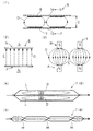
図1および図2は、本発明を実施するための最良の形態の説明に供する。そして、図1の(1)図は、1次側の平断面図(2次側の平断面図)であり、(2)図は、1次側(2次側)の正(側)断面図である。
図2の(1)図は、電磁結合の正(側)断面説明図、(2)図は、磁束分布の正面説明図、(4)図は、渦電流の平面説明図、(5)図は、捻じりコイルの平面説明図である。図4の(2)図は、非接触給電装置の適用例のブロック図である。
《About drawing》
Hereinafter, a non-contact power feeding device of the present invention will be described in detail based on the best mode for carrying out the invention shown in the drawings.
1 and 2 serve to explain the best mode for carrying out the present invention. FIG. 1 (1) is a primary side cross-sectional view (secondary side cross-sectional view), and FIG. 1 (2) is a primary side (secondary side) positive (side) cross-section. FIG.
FIG. 2 (1) is an explanatory diagram of the positive (side) cross section of electromagnetic coupling, (2) is a front explanatory diagram of magnetic flux distribution, (4) is a plan explanatory diagram of eddy current, (5) FIG. These are the plane explanatory views of a twist coil. FIG. 4B is a block diagram of an application example of the non-contact power feeding apparatus.
《非接触給電装置6の概要について》
まず、図2の(1)図,図4の(2)図等を参照して、非接触給電装置6について概説する。
非接触給電装置6において、電磁誘導の相互誘導作用に基づき電力を供給する一般構成は、公知公用である。すなわち、給電時に近接対峙配置された1次側Fの1次コイル7と2次側Gの2次コイル8との間で、1次コイル7での磁束D形成により、2次コイル8に誘導起電力を生成させて、1次コイル7から2次コイル8に電力を送る点は、公知公用である。
そして、図4の(2)図の代表例に示したように、外部地上側の電源9の電源盤に接続された給電側,1次側Fが、マイクロバスその他の電気自動車や電車に車載された受電側,2次側Gに対し、給電時において、物理的接続なしに空隙空間であるエアギャップCを介して対峙配置され、もって電力が送られる。
2次側Gは、例えば車載のバッテリー10に接続されており、給電により充電されたバッテリー10にて、そのモータ11が駆動される。なお12は、給電用の通信制御装置である。
<< About the outline of the non-contact
First, the non-contact
In the non-contact
As shown in the representative example of FIG. 4 (2), the power supply side and the primary side F connected to the power panel of the
The secondary side G is connected to, for example, a vehicle-mounted
上述した電磁誘導の相互誘導作用については、次のとおり。1次側Fの1次コイル7と2次側Gの2次コイル8とを、非接触で対峙配置して、1次コイル7に交流を励磁電流として通電すると、電流に比例した磁界がその軸上に生じ、磁束Dが直角方向に環状に形成される。そして、このように形成され変化する磁束Dが、2次コイル8を貫き鎖交することにより、2次コイル8に起電力が生成される。
このように、磁場を形成し磁界を利用して電力を送る1次コイル7と2次コイル8の両回路は、図2の(1)図に示したように、磁束Dの磁路が形成され電磁結合されており、相互間の結合係数の高低は、1次,2次のコイル7,8の位置,形状,寸法,エアギャップCの距離寸法,磁束Dの漏洩量等によって、変化する。
非接触給電装置6の概要は、このようになっている。
The mutual induction effect of the electromagnetic induction described above is as follows. When the
In this way, both the
The outline of the non-contact
《1次側Fや2次側Gの構造について》
次に、図1,図2の(1)図を参照して、1次側Fや2次側Gの対称構造や内部構造について、説明する。
まず非接触給電装置6は、図2の(1)図に示したように、この種従来例と同様、1次側Fと2次側Gとが、給電時において上下等で対称の同一構造をなす。すなわち非接触給電装置6は、1次側Fが1次コイル7,1次磁心コア13,背板15,カバー16等を備え、2次側Gが、2次コイル8,2次磁心コア14,背板15,カバー16等を備えている。
そして、1次側Fと2次側Gとは、給電時に例えば上下対峙配置された場合、上下対称の同一構造をなす。それぞれ、対称面の内側から外側に向け、カバー16,1次コイル7(2次コイル8),1次磁心コア13(2次磁心コア14),背板15の順に配されている。
<< About the structure of the primary side F and the secondary side G >>
Next, the symmetric structure and internal structure of the primary side F and the secondary side G will be described with reference to FIG. 1 and FIG.
First, as shown in FIG. 2 (1), the non-contact
The primary side F and the secondary side G have the same vertically symmetrical structure when, for example, they are arranged vertically opposite to each other during power feeding. The
又、1次側Fおよび2次側Gの内部構造については、次のとおり。1次側Fの1次コイル7と1次磁心コア13の表面、および2次コイル8と2次磁心コア14の表面は、それぞれ、モールド樹脂17にて被覆固定されている。
すなわち、図1の(2)図に示した例では、1次側F,2次側G共に、背板15とカバー16間にモールド樹脂17が充填され、もって、内部の1次,2次コイル7,8、更には1次,2次磁心コア13,14の表面が、被覆固定されている。
モールド樹脂17は、例えばシリコン樹脂製よりなり、このように内部を固めることにより、1次,2次コイル7,8を位置決め固定し、その機械的強度を確保すると共に、放熱機能も発揮する。すなわち、1次,2次コイル7,8は、励磁電流が流れジュール熱により発熱するが、モールド樹脂17の熱伝導により放熱され、冷却される。
The internal structure of the primary side F and the secondary side G is as follows. The surfaces of the
That is, in the example shown in FIG. 1 (2), the
The
又、このようなモールド樹脂17中には、発泡材18が混入され埋め込まれている。発泡材18は、例えば発泡スチロール,その他の発泡プラスチック製よりなり、モールド樹脂17の量を減らして軽量化を図るべく使用される。
図示例では、このような発泡材18が、1次,2次コイル7,8の内側と外側とに、大小の円環鍔状に周設されているが、図示例によらず、発泡材18の小片群をモールド樹脂17中に混入してもよい。
1次側Fや2次側Gの構造は、このようになっている。
Further, a
In the illustrated example, such a
The structure of the primary side F and the secondary side G is as described above.
《1次,2次コイル7,8や、1次,2次磁心コア13,14について》
次に、図1,図2を参照して、1次,2次コイル7,8、および1次,2次磁心コア13,14について説明する。
1次コイル7および2次コイル8は、導線を同一面で扁平に渦巻き巻回した構造よりなる。1次コイル7や2次コイル8が配設される1次磁心コア13や2次磁心コア14は、平板状をなす。
<< About the primary and
Next, the primary and
The
これらについて、更に詳述する。まず、1次,2次磁心コア13,14は、フェライト製,固化砂鉄製,その他の鉄性材料製のものが代表的であり、透磁率が大の強磁性体よりなり、磁束Dの強力化機能やガイド機能を発揮する。すなわち、1次,2次コイル7,8間インダクタンスを増し、相互間の電磁的結合を強化すると共に、形成された磁束Dを、誘導,収集して,方向付けるべく機能する。
そして、この1次,2次磁心コア13,14は、図1に示したように、凹凸のないフラットな平板状をなす。もって、図2の(2)図に示したように、1次側Fと2次側G間において、極が点在,偏在せず全体化,均一化し、もって形成される磁路の磁束D分布が平行,一様となり、磁束Dの偏在,集中が回避されるようになる(この種従来例に関する図2の(3)図と、比較対照)。
These will be further described in detail. First, the primary and secondary
As shown in FIG. 1, the primary and secondary
これに対応し、1次,2次コイル7,8は、同一平面で渦巻き状に巻回され、もって円状の扁平形状をなす。
すなわち図1に示したように、1次,2次コイル7,8は、ジュール熱損失を低減すべく複数本に並列化されると共に、絶縁された平行導線を、巻回中心部を円空間Hとしつつ、渦巻き状に多数回巻回してなり、もって、全体が円環フランジ状,肉厚の薄い扁平状をなす。そして、このような1次,2次コイル7,8が、それぞれ、対応する1次,2次磁心コア13,14の対称前面側に、近接配設されている。図示例では、当接配設されている。
又、図1の(1)図中に示したように、このように巻回された1次,2次コイル7,8の外径Jと内径Kとの比は、2:1程度に設定されており、このような設定により、1次,2次コイル7,8間の結合係数が高い値となる。この点は、実験によっても裏付けられている。
もって、1次,2次コイル7,8間の電磁的結合が、例え両者間のエアギャップCを広く取っても、強力に保持されるようになる。
Corresponding to this, the primary and
That is, as shown in FIG. 1, the primary and
Further, as shown in FIG. 1A, the ratio of the outer diameter J to the inner diameter K of the primary and
Therefore, the electromagnetic coupling between the primary and
更に、このように巻回された1次,2次コイル7,8は、一定ピッチ間隔で捻じられている。すなわち、巻回された1次,2次コイル7,8については、図2の(4)図に示したように、紙面に垂直な方向に交番磁束D(励磁電流の交流に対応して変化を伴い交番形成される磁束D)が通過すると、線間に一種の渦電流である環状のループ電流Lが誘起されて流れ、もってジュール熱損失の原因となる。
そこで、この1次,2次コイル7,8にあっては、図2の(5)図に示したように、巻回された複数本の平行導線が、扁平さを維持しつつ、途中で一定ピッチ間隔で捻回されている。すなわち、各捻じり箇所M毎に、複数本m本相互間の位置関係を、順次1本ずつ変換して行き、m回の捻じりにより元の位置関係に戻るように、捻回が実施されている。捻じり箇所Mは、巻回1周当たり例えば5〜6個のピッチで形成される。
このような捻回により、ループ電流Lの起電力が相殺され、ループ電流Lそしてジュール熱損失が、大幅に低減される。
1次,2次コイル7,8、および1次,2次磁心コア13,14は、このようになっている。
Further, the primary and
Therefore, in the primary and
Such twisting cancels the electromotive force of the loop current L, and the loop current L and Joule heat loss are greatly reduced.
The primary and
《作用等》
本発明の非接触給電装置6は、以上説明したように構成されている。そこで、以下のようになる。
(1)この非接触給電装置6では、給電に際し、1次コイル7,1次磁心コア13等を備えた給電側つまり1次側Fと、2次コイル8,2次磁心コア14等を備えた受電側つまり2次側Gとが、エアギャップCを存して対峙配置される。
《Action etc.》
The non-contact
(1) The non-contact
(2)そして、1次側Fの1次コイル7に、励磁電流として交流が通電されると、磁束Dが形成される(図2の(1)図を参照)。
もって、この磁束Dの磁路が、1次側Fの1次コイル7と、2次側Gの2次コイル8間に、形成される。1次コイル7と2次コイル8は、両回路間が電磁結合され、両者間に磁場が形成されて、2次コイル8を磁束Dが貫き、2次コイル8に起電力が生成される。
(2) When an alternating current is applied to the
Accordingly, the magnetic path of the magnetic flux D is formed between the
(3)この非接触給電装置6では、このようにして、電磁誘導の相互誘導作用により、電力が1次側Fから2次側Gに供給される。
すなわち電力が、外部の電源9、そしてこれに接続された1次側Fから供給され、2次側Gにて取出されて、これに接続されたバッテリー10を充電する(図4の(2)図を参照)。
(3) In this non-contact
That is, electric power is supplied from the
(4)さてそこで、この非接触給電装置6にあっては、次のようになる。まず、この非接触給電装置6では、平板状の1次,2次磁心コア13,14と、扁平渦巻き巻回された1次,2次コイル7,8とが、組合わせて採用されている。
そこで、給電に際し対峙配置された1次側Fと2次側G間のエアギャップC中の磁路において、磁束Dが平行,一様,疎に分布するようになり、磁束D密度が低くなる(図2の(2)図と、この種従来例に関する図2の(3)図とを、比較対照)。
空気中の磁束D密度と、その磁束Dを形成させる起磁力とは、比例関係にあるので、このように磁束D密度が低いことにより、磁束D形成用の起磁力そして励磁電流が小さくて済み、回路のジュール熱損失もその分低減される。
そこで例えば、同じ密度の磁束Dが形成される場合は、本発明の方が前述したこの種従来例より、はるかに小さな起磁力,励磁電流,ジュール熱損失で済むようになる。
(4) Then, in this non-contact
Therefore, in the magnetic path in the air gap C between the primary side F and the secondary side G arranged opposite to each other during power feeding, the magnetic flux D is distributed in a parallel, uniform, and sparse manner, and the magnetic flux D density is lowered. (Comparison between FIG. 2 (2) and FIG. 2 (3) for this type of conventional example).
Since the magnetic flux D density in the air and the magnetomotive force that forms the magnetic flux D are in a proportional relationship, the low magnetic flux D density can reduce the magnetomotive force and excitation current for forming the magnetic flux D. The Joule heat loss of the circuit is also reduced accordingly.
Therefore, for example, when magnetic fluxes D having the same density are formed, the present invention requires far smaller magnetomotive force, exciting current, and Joule heat loss than the above-described conventional example.
(5)更にこの点は、この非接触給電装置6の1次,2次コイル7,8を、一定の捻じり箇所Mで捻回しておくことによって、一段と促進される(図2の(5)図を参照)。
すなわち、このような捻回により、一種の渦電流であるループ電流L(図2の(4)図を参照)について、その起電力が相殺され、もって、ループ電流Lそしてジュール熱損失が、大幅に低減されるようになる。
例えば、このような上記(4),(5)の点に基づき、この非接触給電装置6は、充電効率が、前述したこの種従来例の86%に対し、92%程度まで高効率化される。
(5) Further, this point is further promoted by twisting the primary and
That is, by such twisting, the electromotive force of the loop current L (see FIG. 2 (4)), which is a kind of eddy current, is offset, and the loop current L and Joule heat loss are greatly reduced. To be reduced.
For example, based on the above points (4) and (5), the non-contact
(6)又、この非接触給電装置6は、平板状の1次,2次磁心コア13,14と、扁平渦巻き状の1次,2次コイル7,8とを、組合わせて採用したので、上述したように、磁束Dの密度が低く、磁束Dを形成する起磁力,励磁電流が小さくて済む。
そこで、1次,2次コイル7,8間のエアギャップCを、その分だけ広く設定することが可能となる。例えば、同じ値の励磁電流の場合、本発明の方が前述したこの種従来例より、エアギャップCをより広く設定することが可能となり、エアギャップCが50mm程度であったこの種従来例に比し、エアギャップCを100mmに倍増可能となる。
(6) Since the non-contact
Therefore, the air gap C between the primary and
(7)なおこの点は、渦巻き巻回されたこの非接触給電装置6の1次,2次コイル7,8について、その外径Jと内径Kとの比を、2:1程度としておくことによって、フォローされる。
すなわち、これにより1次,2次コイル7,8間について、高い結合係数が得られるので、エアギャップCを広くしても、両者間の強力な電磁結合が維持される。
(7) In this respect, the ratio of the outer diameter J to the inner diameter K of the primary and
That is, since a high coupling coefficient can be obtained between the primary and
(8)更に、この非接触給電装置6は、平板状の1次,2次磁心コア13,14と、扁平な1次,2次コイル7,8とを採用したので、1次側F,2次側G共に、その肉厚Eが薄く、その分だけ小型,軽量化される(図1の(2)図と、この種従来例に関する図3の(2)図,(3)図とを、比較対照)。肉厚Eは、前述したこの種従来例に比し、半減される。
(8) Furthermore, since the non-contact
(9)又、このような非接触給電装置6の軽量化は、1次側F,2次側Gのモールド樹脂17中に、発泡材18を混入しておくことにより(図1を参照)、更に促進される。すなわち、発泡材18を混入した分だけ、モールド樹脂17の充填量が減らされ、もって一段と軽量化が進むようになる。
例えば、このような上記(8),(9)の点に基づき、この非接触給電装置6は、2次側Bつまりピックアップの重量が、前述したこの種従来例の70kg程度に対し、35kg程度と半減される。
(9) Moreover, the weight reduction of such a non-contact
For example, on the basis of the above points (8) and (9), the non-contact
《その他》
なお、図示例等に基づき以上説明したところによれば、1次コイル7および2次コイル8は、共に、同一面で扁平に渦巻き巻回された構造よりなり、かつ、このような1次コイル7や2次コイル8が配設される1次磁心コア13や2次磁心コア14は、共に、平板状をなした構造よりなっていた。
しかしながら、非接触給電装置6については、このような構成によらず、次のような構成も考えられる。
すなわち、1次コイル7又は2次コイル8のいずれか一方側のみ、例えば1次コイル7のみを、上述した同一面で扁平に渦巻き巻回された構造とし、かつ、それが配設される一方側の1次磁心コア13又は2次磁心コア14のみを、平板状の構造とした構成が考えられる。この場合には、このような構造,構成が採用されない他方側は、前述したこの種従来例の1次コイル1又は2次コイル2や、凹凸形状をなす1次磁心コア4又は2次磁心コア5を、使用可能である。
このような構成例として、代表的には、同一平面で扁平に渦巻き巻回された構造の1次コイル7と、平板状をなす構造の1次磁心コア13とを、1次側として採用した構成の非接触給電装置6が、考えられる。
この場合には、このような1次側は、単独かつ2次側とは別体の構成として、成立、適用可能である。
そして、このような非接触給電装置6について、その機能,作用,効果等については、図示例等に基づき前述した所が、準用される。
このように、本発明思想のより広い適用も、考えられる。
<Others>
According to the above description based on the illustrated example, the
However, the following configuration is also conceivable for the non-contact
That is, only one side of the
As such a configuration example, the
In this case, such a primary side can be established and applied as a single and separate configuration from the secondary side.
And about such a non-contact
Thus, a wider application of the inventive idea is also conceivable.
1 1次コイル(従来例)
2 2次コイル(従来例)
3 非接触給電装置(従来例)
4 1次磁心コア(従来例)
5 2次磁心コア(従来例)
6 非接触給電装置(本発明)
7 1次コイル(本発明)
8 2次コイル(本発明)
9 電源
10 バッテリー
11 モータ
12 通信制御装置
13 1次磁心コア(本発明)
14 2次磁心コア(本発明)
15 背板
16 カバー
17 モールド樹脂
18 発泡材
A 1次側(従来例)
B 2次側(従来例)
C エアギャップ
D 磁束
E 肉厚
F 1次側(本発明)
G 2次側(本発明)
H 円空間
J 外径
K 内径
L ループ電流
M 捻じり箇所
1 Primary coil (conventional example)
2 Secondary coil (conventional example)
3 Non-contact power feeding device (conventional example)
4 Primary magnetic core (conventional example)
5 Secondary magnetic core (conventional example)
6 Non-contact power feeding device (present invention)
7 Primary coil (present invention)
8 Secondary coil (present invention)
9
14 Secondary magnetic core (present invention)
15
B Secondary side (conventional example)
C Air gap D Magnetic flux E Wall thickness F Primary side (Invention)
G secondary side (present invention)
H Circular space J Outer diameter K Inner diameter L Loop current M Twist location
Claims (2)
該1次コイルおよび2次コイルは、複数本に並列化されると共に絶縁された平行導線を、巻回中心部を円空間としつつ、同一面で渦巻き状に多数回巻回してなり、もって円状の扁平形状をなすと共に、外径と内径との比が2:1程度に設定されており、
かつ、該1次コイルおよび2次コイルは、巻回された複数本の該平行導線が、扁平さを維持しつつ途中で捻回されてなり、その捻じりは、各捻じり箇所毎に、複数本相互間の位置関係を順次1本ずつ変換して行くことにより実施されており、
該1次コイルや2次コイルが配設される磁心コアは、平板状をなすこと、を特徴とする非接触給電装置。 In the non-contact power feeding device that supplies power from the primary coil to the secondary coil based on the mutual induction action of electromagnetic induction,
The primary coil and the secondary coil are formed by winding a plurality of parallel and insulated parallel conductors in a spiral shape on the same surface while making the winding central part a circular space. And the ratio of the outer diameter to the inner diameter is set to about 2: 1,
And, the primary coil and the secondary coil are formed by twisting a plurality of the wound parallel conductive wires in the middle while maintaining the flatness. It is implemented by converting the positional relationship between multiples one by one sequentially,
The non-contact power feeding device, wherein the magnetic core in which the primary coil and the secondary coil are disposed has a flat plate shape.
該モールド樹脂は、該1次コイルおよび2次コイルを位置決め固定し、その機械的強度を確保すると共に、該1次コイルおよび2次コイルのジュール熱発熱を熱伝導により放熱する放熱機能も発揮し、
該発泡材は、その混入によりその分だけ該モールド樹脂の量を減らして、全体重量を軽減する機能を発揮すること、を特徴とする非接触給電装置。 The contactless power supply device according to claim 1, wherein the primary coil and the surface of the magnetic core, and the secondary coil and the surface of the magnetic core are coated and fixed with a mold resin, respectively. , Foam material is mixed in the mold resin,
The mold resin positions and fixes the primary coil and the secondary coil to ensure the mechanical strength, and also exhibits a heat dissipation function to dissipate Joule heat generated by the primary coil and the secondary coil by heat conduction. ,
The non-contact power feeding apparatus, wherein the foam material exhibits a function of reducing the total weight by reducing the amount of the mold resin by the amount of mixing.
Priority Applications (4)
| Application Number | Priority Date | Filing Date | Title |
|---|---|---|---|
| JP2006273933A JP4356844B2 (en) | 2006-10-05 | 2006-10-05 | Non-contact power feeding device |
| CN2007101630253A CN101179208B (en) | 2006-10-05 | 2007-09-28 | Non-contact power supplying apparatus |
| TW096136849A TWI376856B (en) | 2006-10-05 | 2007-10-02 | Non-contact electric power supply device |
| KR1020070099708A KR100976061B1 (en) | 2006-10-05 | 2007-10-04 | Non-contact electric power supply device |
Applications Claiming Priority (1)
| Application Number | Priority Date | Filing Date | Title |
|---|---|---|---|
| JP2006273933A JP4356844B2 (en) | 2006-10-05 | 2006-10-05 | Non-contact power feeding device |
Publications (2)
| Publication Number | Publication Date |
|---|---|
| JP2008087733A JP2008087733A (en) | 2008-04-17 |
| JP4356844B2 true JP4356844B2 (en) | 2009-11-04 |
Family
ID=39372299
Family Applications (1)
| Application Number | Title | Priority Date | Filing Date |
|---|---|---|---|
| JP2006273933A Active JP4356844B2 (en) | 2006-10-05 | 2006-10-05 | Non-contact power feeding device |
Country Status (4)
| Country | Link |
|---|---|
| JP (1) | JP4356844B2 (en) |
| KR (1) | KR100976061B1 (en) |
| CN (1) | CN101179208B (en) |
| TW (1) | TWI376856B (en) |
Cited By (3)
| Publication number | Priority date | Publication date | Assignee | Title |
|---|---|---|---|---|
| WO2013128554A1 (en) | 2012-02-27 | 2013-09-06 | 株式会社日立エンジニアリング・アンド・サービス | Wireless power supply apparatus |
| EP2688182A2 (en) | 2012-07-19 | 2014-01-22 | Hitachi Power Solutions Co., Ltd. | Wireless charging system |
| US9887568B2 (en) | 2010-02-12 | 2018-02-06 | Semiconductor Energy Laboratory Co., Ltd. | Moving object, wireless power feeding system, and wireless power feeding method |
Families Citing this family (102)
| Publication number | Priority date | Publication date | Assignee | Title |
|---|---|---|---|---|
| US9466419B2 (en) | 2007-05-10 | 2016-10-11 | Auckland Uniservices Limited | Apparatus and system for charging a battery |
| JP4752879B2 (en) * | 2008-07-04 | 2011-08-17 | パナソニック電工株式会社 | Planar coil |
| TWI382628B (en) * | 2008-07-23 | 2013-01-11 | Darfon Electronics Corp | Energy transferring system |
| JP5490385B2 (en) * | 2008-08-04 | 2014-05-14 | 昭和飛行機工業株式会社 | Non-contact power feeding device |
| JP4743244B2 (en) * | 2008-09-18 | 2011-08-10 | トヨタ自動車株式会社 | Non-contact power receiving device |
| US20110049978A1 (en) | 2008-10-02 | 2011-03-03 | Toyota Jidosha Kabushiki Kaisha | Self-resonant coil, non-contact electric power transfer device and vehicle |
| JP5274989B2 (en) * | 2008-11-12 | 2013-08-28 | 昭和飛行機工業株式会社 | Non-contact power feeding device |
| US8499910B2 (en) * | 2008-11-18 | 2013-08-06 | Stemmann-Technik Gmbh | Device for transmitting electrical energy |
| KR100944113B1 (en) * | 2009-02-27 | 2010-02-24 | 한국과학기술원 | Power supply system and method for electric vehicle |
| CN101841173B (en) | 2009-03-19 | 2013-04-24 | 鸿富锦精密工业(深圳)有限公司 | Charging system |
| WO2010137495A1 (en) * | 2009-05-26 | 2010-12-02 | 有限会社日本テクモ | Contactless electric-power supplying device |
| JP5891419B2 (en) * | 2009-06-02 | 2016-03-23 | パナソニックIpマネジメント株式会社 | Power supply device |
| JP5354539B2 (en) * | 2009-08-25 | 2013-11-27 | 国立大学法人埼玉大学 | Non-contact power feeding device |
| KR101087769B1 (en) * | 2009-10-08 | 2011-11-30 | 한국과학기술원 | Power supply device for electric vehicle |
| JP2011124129A (en) | 2009-12-11 | 2011-06-23 | Showa Aircraft Ind Co Ltd | High-frequency electric wire |
| KR20120104615A (en) | 2009-12-24 | 2012-09-21 | 러스크 인텔렉츄얼 리저브 아게 | Electric vehicle and electric supply arrangement for the same |
| US8937454B2 (en) | 2010-01-05 | 2015-01-20 | Access Business Group International Llc | Inductive charging system for electric vehicle |
| JP5530783B2 (en) * | 2010-03-31 | 2014-06-25 | 日本写真印刷株式会社 | Method for producing molded product with coil |
| JP2011223703A (en) | 2010-04-07 | 2011-11-04 | Showa Aircraft Ind Co Ltd | Portable type non-contact power supply device |
| JP2011258807A (en) | 2010-06-10 | 2011-12-22 | Showa Aircraft Ind Co Ltd | Non-contact power feeding device |
| EP2587629A1 (en) | 2010-06-28 | 2013-05-01 | Showa Aircraft Industry Co., Ltd. | Non-contact electric power feeding device |
| US8917511B2 (en) | 2010-06-30 | 2014-12-23 | Panasonic Corporation | Wireless power transfer system and power transmitting/receiving device with heat dissipation structure |
| EP2620960B1 (en) | 2010-09-21 | 2019-11-27 | Panasonic Intellectual Property Management Co., Ltd. | Contactless power feeding apparatus |
| JP5562797B2 (en) * | 2010-10-18 | 2014-07-30 | 昭和飛行機工業株式会社 | Primary coil arrangement structure of non-contact power feeding device |
| CN101977454A (en) * | 2010-10-27 | 2011-02-16 | 吴成武 | Electromagnetic induction conversion device |
| KR101213086B1 (en) | 2010-11-04 | 2012-12-18 | 유한회사 한림포스텍 | Method for controlling wireless power signal in wireless power transmission device and wireless power transmission using the same |
| JP5075973B2 (en) | 2010-12-20 | 2012-11-21 | 昭和飛行機工業株式会社 | Non-contact power feeder with multi-pole coil structure |
| JP5818431B2 (en) | 2010-12-21 | 2015-11-18 | 東海旅客鉄道株式会社 | Transformer |
| EP2667390B1 (en) | 2011-01-19 | 2018-10-31 | Technova Inc. | Contactless power transfer system |
| WO2012101729A1 (en) | 2011-01-26 | 2012-08-02 | パナソニック株式会社 | Non-contact charging module and non-contact charging instrument |
| JP5316558B2 (en) * | 2011-02-03 | 2013-10-16 | 株式会社デンソー | Contactless charging system |
| US9184633B2 (en) | 2011-02-03 | 2015-11-10 | Denso Corporation | Non-contact power supply control device, non-contact power supply system, and non-contact power charge system |
| KR101182376B1 (en) * | 2011-04-26 | 2012-09-12 | 한국과학기술원 | Magnetic Inductive Apparatus for Power Transmission, Power Collection and Power Transmission Considering Horizontal Deviation |
| EP2524834A1 (en) | 2011-05-18 | 2012-11-21 | Brusa Elektronik AG | Device for inductive charging of at least one electrical energy storage device of an electric car |
| EP2711945A4 (en) * | 2011-05-19 | 2014-11-05 | Toyota Motor Co Ltd | Power-reception device, power-transmission device, and power-transfer system |
| JP6067211B2 (en) | 2011-05-27 | 2017-01-25 | 日産自動車株式会社 | Non-contact power feeding device |
| JP5315465B2 (en) * | 2011-06-08 | 2013-10-16 | パナソニック株式会社 | Non-contact power feeding device |
| WO2012172812A1 (en) | 2011-06-14 | 2012-12-20 | パナソニック株式会社 | Communication apparatus |
| KR101111744B1 (en) * | 2011-09-02 | 2012-02-15 | 한국과학기술원 | Power supply device for electric vehicle |
| KR101111289B1 (en) * | 2011-09-02 | 2012-02-22 | 한국과학기술원 | Power supply device for electric vehicle |
| KR101114601B1 (en) * | 2011-09-02 | 2012-02-24 | 한국과학기술원 | Power supply device for electric vehicle |
| AU2012317038B2 (en) * | 2011-09-26 | 2014-10-30 | Korea Advanced Institute Of Science And Technology | Power supply and pickup system capable of maintaining stability of transmission efficiency despite changes in resonant frequency |
| DE102011116253B3 (en) * | 2011-10-18 | 2012-05-24 | Audi Ag | Electric vehicle with shielding element against electromagnetic radiation |
| JP2015008551A (en) * | 2011-10-28 | 2015-01-15 | パナソニック株式会社 | Non-contact power transmission device |
| EP2773012B1 (en) | 2011-10-28 | 2018-02-28 | Panasonic Intellectual Property Management Co., Ltd. | Contactless electrical power transmission device, and electricity supply device and electricity reception device using same |
| WO2013061612A1 (en) | 2011-10-28 | 2013-05-02 | パナソニック株式会社 | Contactless power transmission device |
| US10204734B2 (en) | 2011-11-02 | 2019-02-12 | Panasonic Corporation | Electronic device including non-contact charging module and near field communication antenna |
| JP5988146B2 (en) * | 2011-11-15 | 2016-09-07 | パナソニックIpマネジメント株式会社 | Transmission coil and portable radio terminal |
| WO2013065245A1 (en) | 2011-11-02 | 2013-05-10 | パナソニック株式会社 | Non-contact wireless communication coil, transmission coil, and portable wireless terminal |
| JPWO2013099221A1 (en) | 2011-12-27 | 2015-04-30 | パナソニックIpマネジメント株式会社 | Non-contact charger |
| JP2013169122A (en) | 2012-02-17 | 2013-08-29 | Panasonic Corp | Non-contact charge module and portable terminal having the same |
| US9583259B2 (en) * | 2012-03-20 | 2017-02-28 | Qualcomm Incorporated | Wireless power transfer device and method of manufacture |
| US9431834B2 (en) * | 2012-03-20 | 2016-08-30 | Qualcomm Incorporated | Wireless power transfer apparatus and method of manufacture |
| US9653206B2 (en) | 2012-03-20 | 2017-05-16 | Qualcomm Incorporated | Wireless power charging pad and method of construction |
| US9160205B2 (en) | 2012-03-20 | 2015-10-13 | Qualcomm Incorporated | Magnetically permeable structures |
| CN104756357B (en) * | 2012-03-20 | 2019-03-29 | 奥克兰联合服务有限公司 | Winding arrangement in wireless power transmission system |
| JP5903990B2 (en) * | 2012-03-30 | 2016-04-13 | 株式会社デンソー | Contactless power supply |
| JP5885837B2 (en) | 2012-05-21 | 2016-03-16 | 株式会社テクノバ | Contactless power transformer for moving objects |
| WO2013183665A1 (en) | 2012-06-05 | 2013-12-12 | 国立大学法人 埼玉大学 | Contactless feeding transformer |
| DE102012209898A1 (en) * | 2012-06-13 | 2013-12-19 | Siemens Aktiengesellschaft | Arrangement for inductive wireless delivery of energy |
| JP6112383B2 (en) | 2012-06-28 | 2017-04-12 | パナソニックIpマネジメント株式会社 | Mobile device |
| KR101318395B1 (en) | 2012-07-13 | 2013-10-15 | 한국과학기술원 | Flat coil, power supply and collector device for magnetic induction power transmission |
| JP2014033524A (en) * | 2012-08-02 | 2014-02-20 | Kojima Press Industry Co Ltd | Non-contact power supply system for unmanned carrier |
| JP6054408B2 (en) * | 2012-10-12 | 2016-12-27 | 株式会社日立パワーソリューションズ | Non-contact power feeding device |
| US9376026B2 (en) | 2012-10-19 | 2016-06-28 | Qualcomm Incorporated | System and method for inductance compensation in wireless power transfer |
| JP5718879B2 (en) * | 2012-10-31 | 2015-05-13 | トヨタ自動車株式会社 | Vehicle parking assist device |
| JP5286445B1 (en) * | 2012-12-28 | 2013-09-11 | 株式会社日立パワーソリューションズ | Wireless power feeder for electric mobile body |
| JP6148501B2 (en) * | 2013-03-01 | 2017-06-14 | 株式会社東芝 | Power transmission system |
| JP6309197B2 (en) | 2013-03-05 | 2018-04-11 | 矢崎総業株式会社 | Coil unit and power supply system |
| WO2014155946A1 (en) | 2013-03-27 | 2014-10-02 | パナソニック株式会社 | Non-contact charging apparatus |
| JP2015012656A (en) | 2013-06-27 | 2015-01-19 | Tdk株式会社 | Wireless power transmission device |
| WO2015040650A1 (en) | 2013-09-17 | 2015-03-26 | パナソニックIpマネジメント株式会社 | Contactless power transmission device |
| WO2015040649A1 (en) | 2013-09-17 | 2015-03-26 | パナソニックIpマネジメント株式会社 | Wireless power transmission device |
| JP6123607B2 (en) * | 2013-09-24 | 2017-05-10 | トヨタ自動車株式会社 | vehicle |
| DE102013219540A1 (en) * | 2013-09-27 | 2015-04-02 | Siemens Aktiengesellschaft | Charging device for inductive wireless delivery of energy |
| DE102013219542A1 (en) | 2013-09-27 | 2015-04-02 | Siemens Aktiengesellschaft | Charging device for inductive wireless delivery of energy |
| KR101407205B1 (en) | 2013-10-21 | 2014-06-12 | (주)디아이디 | Coil resonator for wireless power transmission of magnetic resonance and method of fabricating the same |
| DE102013221648B4 (en) * | 2013-10-24 | 2023-07-27 | Bayerische Motoren Werke Aktiengesellschaft | Theft protection for the primary coil of an inductive charging station |
| JP6453545B2 (en) * | 2014-02-14 | 2019-01-16 | 矢崎総業株式会社 | Power receiving unit and power supply system having the same |
| KR101771381B1 (en) | 2014-05-15 | 2017-08-24 | 닛산 지도우샤 가부시키가이샤 | Wireless power supply device |
| WO2015190240A1 (en) | 2014-06-12 | 2015-12-17 | 矢崎総業株式会社 | Bezel member and vehicular display device |
| CN105322586A (en) * | 2014-07-26 | 2016-02-10 | 王东奎 | Transformer for electric vehicle charging and application method of transformer |
| CN105304960B (en) * | 2014-07-26 | 2021-04-09 | 王东奎 | Charging method and device for electric vehicle |
| CN105281392B (en) * | 2014-07-26 | 2020-07-03 | 王东奎 | Electric vehicle charging pile |
| CN105281411B (en) * | 2014-07-26 | 2020-07-03 | 王东奎 | Charging device for electric vehicle |
| CN105305516B (en) * | 2014-07-28 | 2020-07-03 | 王东奎 | Charging system and butt-joint charging electric automobile thereof |
| EP3041007A1 (en) * | 2014-11-27 | 2016-07-06 | Brusa Elektronik AG | Shield for a contactless energy transmission system with improved coupling and improved leakage field |
| EP3235096B1 (en) * | 2014-12-16 | 2020-08-19 | Hewlett-Packard Development Company, L.P. | Wireless chargers |
| JP6485080B2 (en) | 2015-02-02 | 2019-03-20 | 株式会社Ihi | Coil device mounting structure and coil device |
| JP6541425B2 (en) * | 2015-05-18 | 2019-07-10 | 株式会社テクノバ | Wireless power supply system |
| JP6534152B2 (en) * | 2015-06-11 | 2019-06-26 | 昭和飛行機工業株式会社 | Power transmission / reception inductor |
| KR102441822B1 (en) * | 2015-08-10 | 2022-09-13 | 주식회사 아모센스 | wireless charging transmission module for car |
| CN106972554A (en) * | 2016-01-13 | 2017-07-21 | 深圳市昭行云科技有限公司 | Power supply connecting device |
| JP6453787B2 (en) * | 2016-02-04 | 2019-01-16 | 矢崎総業株式会社 | Winding unit |
| WO2017169543A1 (en) * | 2016-03-29 | 2017-10-05 | 株式会社村田製作所 | Coil antenna, power-feeding device, power-receiving device, and wireless power supply system |
| JP6589759B2 (en) | 2016-07-07 | 2019-10-16 | 株式会社Ihi | Coil device |
| WO2018222758A1 (en) | 2017-05-30 | 2018-12-06 | Wireless Advanced Vehicle Electrification, Inc. | Single feed multi-pad wireless charging |
| JP6669710B2 (en) * | 2017-11-16 | 2020-03-18 | 矢崎総業株式会社 | Power transmission communication unit |
| US11462943B2 (en) | 2018-01-30 | 2022-10-04 | Wireless Advanced Vehicle Electrification, Llc | DC link charging of capacitor in a wireless power transfer pad |
| CN110048515B (en) * | 2019-05-23 | 2023-11-28 | 昆山联滔电子有限公司 | Wireless charging module and manufacturing process thereof |
| DE102019209141A1 (en) * | 2019-06-25 | 2020-12-31 | Mahle International Gmbh | Method for manufacturing an inductive charging device |
| CN111261392A (en) * | 2019-12-20 | 2020-06-09 | 南京矽力微电子技术有限公司 | Power transformer and method for manufacturing the same |
Family Cites Families (4)
| Publication number | Priority date | Publication date | Assignee | Title |
|---|---|---|---|---|
| JP3432317B2 (en) * | 1994-11-18 | 2003-08-04 | エヌイーシートーキン株式会社 | Cordless power station |
| JP2002299138A (en) * | 2001-04-02 | 2002-10-11 | Kawasaki Steel Corp | Planar magnetic element for noncontact charger |
| KR100541029B1 (en) * | 2004-01-06 | 2006-01-12 | (주)제이씨 프로텍 | Wireless charging device of various electromagnetic wave |
| KR100573411B1 (en) * | 2004-03-05 | 2006-04-25 | 한국철도기술연구원 | Non contact collection power system for power supply of electric car |
-
2006
- 2006-10-05 JP JP2006273933A patent/JP4356844B2/en active Active
-
2007
- 2007-09-28 CN CN2007101630253A patent/CN101179208B/en active Active
- 2007-10-02 TW TW096136849A patent/TWI376856B/en active
- 2007-10-04 KR KR1020070099708A patent/KR100976061B1/en active IP Right Grant
Cited By (4)
| Publication number | Priority date | Publication date | Assignee | Title |
|---|---|---|---|---|
| US9887568B2 (en) | 2010-02-12 | 2018-02-06 | Semiconductor Energy Laboratory Co., Ltd. | Moving object, wireless power feeding system, and wireless power feeding method |
| WO2013128554A1 (en) | 2012-02-27 | 2013-09-06 | 株式会社日立エンジニアリング・アンド・サービス | Wireless power supply apparatus |
| US9577464B2 (en) | 2012-02-27 | 2017-02-21 | Hitachi Power Solutions Co., Ltd. | Wireless charging system |
| EP2688182A2 (en) | 2012-07-19 | 2014-01-22 | Hitachi Power Solutions Co., Ltd. | Wireless charging system |
Also Published As
| Publication number | Publication date |
|---|---|
| KR20080031795A (en) | 2008-04-11 |
| CN101179208B (en) | 2010-08-18 |
| CN101179208A (en) | 2008-05-14 |
| KR100976061B1 (en) | 2010-08-17 |
| TW200828720A (en) | 2008-07-01 |
| JP2008087733A (en) | 2008-04-17 |
| TWI376856B (en) | 2012-11-11 |
Similar Documents
| Publication | Publication Date | Title |
|---|---|---|
| JP4356844B2 (en) | Non-contact power feeding device | |
| JP6081469B2 (en) | Inductive power transfer system transmitter | |
| JP6400663B2 (en) | Contactless power transformer | |
| JP2010093180A (en) | Non-contact power supply | |
| US20110304217A1 (en) | Non-contact power feeding device | |
| JP5274989B2 (en) | Non-contact power feeding device | |
| US20120153741A1 (en) | Non-contact power feeding apparatus | |
| JP2012151311A (en) | Core for non-contact power supply | |
| JP2017168522A (en) | Coil device | |
| JP6300107B2 (en) | Non-contact power transmission device | |
| WO2021051993A1 (en) | Wireless charging device | |
| JP2017212880A (en) | Wireless power transmission apparatus | |
| JP2015106581A (en) | Power transmission coil unit and wireless power transmission device | |
| JP2014103735A (en) | Non-contact power supply unit | |
| JP6476721B2 (en) | Power receiving coil device and non-contact power feeding system | |
| JP5918020B2 (en) | Non-contact power supply coil | |
| JP6537071B2 (en) | External demagnetization type non-contact power supply device | |
| JP5896226B2 (en) | Contactless power supply | |
| JP2015015452A (en) | Coil device for wireless power transmission | |
| JP2014063768A (en) | Coil unit used for non-contact power supply system | |
| JP2015130734A (en) | non-contact power supply device | |
| JP2017212302A (en) | Coil device, non-contact power supply device and non-contact power reception device | |
| JP6532086B2 (en) | Externally shielded non-contact power supply | |
| WO2018180313A1 (en) | Coil apparatus | |
| JP6302365B2 (en) | Coil device for non-contact power supply |
Legal Events
| Date | Code | Title | Description |
|---|---|---|---|
| A871 | Explanation of circumstances concerning accelerated examination |
Free format text: JAPANESE INTERMEDIATE CODE: A871 Effective date: 20081209 |
|
| A621 | Written request for application examination |
Free format text: JAPANESE INTERMEDIATE CODE: A621 Effective date: 20081201 |
|
| A975 | Report on accelerated examination |
Free format text: JAPANESE INTERMEDIATE CODE: A971005 Effective date: 20090209 |
|
| A131 | Notification of reasons for refusal |
Free format text: JAPANESE INTERMEDIATE CODE: A131 Effective date: 20090303 |
|
| A521 | Request for written amendment filed |
Free format text: JAPANESE INTERMEDIATE CODE: A523 Effective date: 20090422 |
|
| TRDD | Decision of grant or rejection written | ||
| A01 | Written decision to grant a patent or to grant a registration (utility model) |
Free format text: JAPANESE INTERMEDIATE CODE: A01 Effective date: 20090728 |
|
| A01 | Written decision to grant a patent or to grant a registration (utility model) |
Free format text: JAPANESE INTERMEDIATE CODE: A01 |
|
| A61 | First payment of annual fees (during grant procedure) |
Free format text: JAPANESE INTERMEDIATE CODE: A61 Effective date: 20090729 |
|
| FPAY | Renewal fee payment (event date is renewal date of database) |
Free format text: PAYMENT UNTIL: 20120814 Year of fee payment: 3 |
|
| R150 | Certificate of patent or registration of utility model |
Ref document number: 4356844 Country of ref document: JP Free format text: JAPANESE INTERMEDIATE CODE: R150 Free format text: JAPANESE INTERMEDIATE CODE: R150 |
|
| FPAY | Renewal fee payment (event date is renewal date of database) |
Free format text: PAYMENT UNTIL: 20120814 Year of fee payment: 3 |
|
| FPAY | Renewal fee payment (event date is renewal date of database) |
Free format text: PAYMENT UNTIL: 20150814 Year of fee payment: 6 |
|
| R250 | Receipt of annual fees |
Free format text: JAPANESE INTERMEDIATE CODE: R250 |
|
| R250 | Receipt of annual fees |
Free format text: JAPANESE INTERMEDIATE CODE: R250 |
|
| R250 | Receipt of annual fees |
Free format text: JAPANESE INTERMEDIATE CODE: R250 |
|
| R250 | Receipt of annual fees |
Free format text: JAPANESE INTERMEDIATE CODE: R250 |
|
| R250 | Receipt of annual fees |
Free format text: JAPANESE INTERMEDIATE CODE: R250 |
|
| R250 | Receipt of annual fees |
Free format text: JAPANESE INTERMEDIATE CODE: R250 |
|
| R250 | Receipt of annual fees |
Free format text: JAPANESE INTERMEDIATE CODE: R250 |
|
| R250 | Receipt of annual fees |
Free format text: JAPANESE INTERMEDIATE CODE: R250 |