JP4355250B2 - Digital camera - Google Patents
Digital camera Download PDFInfo
- Publication number
- JP4355250B2 JP4355250B2 JP2004107071A JP2004107071A JP4355250B2 JP 4355250 B2 JP4355250 B2 JP 4355250B2 JP 2004107071 A JP2004107071 A JP 2004107071A JP 2004107071 A JP2004107071 A JP 2004107071A JP 4355250 B2 JP4355250 B2 JP 4355250B2
- Authority
- JP
- Japan
- Prior art keywords
- exposure
- battery
- image
- digital camera
- timer
- Prior art date
- Legal status (The legal status is an assumption and is not a legal conclusion. Google has not performed a legal analysis and makes no representation as to the accuracy of the status listed.)
- Expired - Fee Related
Links
Images


Classifications
-
- H—ELECTRICITY
- H04—ELECTRIC COMMUNICATION TECHNIQUE
- H04N—PICTORIAL COMMUNICATION, e.g. TELEVISION
- H04N23/00—Cameras or camera modules comprising electronic image sensors; Control thereof
- H04N23/60—Control of cameras or camera modules
- H04N23/65—Control of camera operation in relation to power supply
- H04N23/651—Control of camera operation in relation to power supply for reducing power consumption by affecting camera operations, e.g. sleep mode, hibernation mode or power off of selective parts of the camera
-
- H—ELECTRICITY
- H04—ELECTRIC COMMUNICATION TECHNIQUE
- H04N—PICTORIAL COMMUNICATION, e.g. TELEVISION
- H04N23/00—Cameras or camera modules comprising electronic image sensors; Control thereof
- H04N23/60—Control of cameras or camera modules
- H04N23/63—Control of cameras or camera modules by using electronic viewfinders
- H04N23/633—Control of cameras or camera modules by using electronic viewfinders for displaying additional information relating to control or operation of the camera
- H04N23/634—Warning indications
-
- H—ELECTRICITY
- H04—ELECTRIC COMMUNICATION TECHNIQUE
- H04N—PICTORIAL COMMUNICATION, e.g. TELEVISION
- H04N23/00—Cameras or camera modules comprising electronic image sensors; Control thereof
- H04N23/70—Circuitry for compensating brightness variation in the scene
Landscapes
- Engineering & Computer Science (AREA)
- Multimedia (AREA)
- Signal Processing (AREA)
- Studio Devices (AREA)
- Camera Bodies And Camera Details Or Accessories (AREA)
- Exposure Control For Cameras (AREA)
- Details Of Cameras Including Film Mechanisms (AREA)
- Indication In Cameras, And Counting Of Exposures (AREA)
- Stroboscope Apparatuses (AREA)
Description
本発明は、数秒以上の長時間露光による撮影が可能なデジタルカメラに関する。 The present invention relates to a digital camera capable of photographing by long exposure of several seconds or more.
デジタルカメラには、シャッタボタンを押し続けている間は露光状態を継続するバルブ撮影や通常撮影時よりも露光時間の長いスローシャッタ撮影等のように、数秒以上の長時間露光による撮影が可能なタイプがある。この長時間露光による撮影前には、バッテリー電圧低下による誤動作を防止するため、バッテリーチェックが予め行なわれている。バッテリーチェックでは、バッテリー電圧が所定のバッテリーチェックレベル(以下、「BCレベル」という)未満であるか否かを判定し、BCレベル以上であった場合にのみ撮影動作を開始させる。一方、バッテリー電圧がBCレベル未満であった場合は、バッテリー残量がない旨を警告して使用者にバッテリー交換を促したり、残量不足のバッテリーの使用を禁止したりしている。
しかしながら、長時間露光による撮影では、通常露光による撮影よりも露光時間が大幅に長いため、撮影前のバッテリチェック結果がOKであっても、露光途中にバッテリー電圧がBCレベル未満に低下してしまうことがある。従来では露光途中にバッテリー電圧がBCレベル未満となると、全カメラ動作を強制終了していたため、撮影画像を得ることができず、撮影に失敗してしまうことがあった。 However, in shooting with long exposure, the exposure time is significantly longer than in shooting with normal exposure, so even if the battery check result before shooting is OK, the battery voltage falls below the BC level during exposure. Sometimes. Conventionally, when the battery voltage becomes lower than the BC level during exposure, all the camera operations are forcibly terminated, so that a photographed image cannot be obtained and photographing may fail.
本発明は、上記課題に鑑みてなされたものであり、露光中にバッテリ不足となっても撮影画像が得られるデジタルカメラを提供することを目的とする。 The present invention has been made in view of the above problems, and an object of the present invention is to provide a digital camera that can obtain a captured image even when a battery becomes insufficient during exposure.
本発明は、デジタルカメラの撮影画像はデジタル画像処理によって補正できることに着目し、露光中にバッテリー電圧が低下して露光が強制終了された場合には、該強制終了前までに蓄積された撮像手段の画像信号から撮影画像を取得し、この撮影画像にデジタル画像処理を施すことによって撮影失敗を救済しようとするものである。 The present invention pays attention to the fact that a photographed image of a digital camera can be corrected by digital image processing. When the battery voltage is lowered during exposure and the exposure is forcibly terminated, the imaging means accumulated before the forcible termination The photographed image is acquired from the image signal, and the photographed image is subjected to digital image processing to thereby remedy the photographing failure.
すなわち、本発明は、撮影レンズにより形成された被写体像を受光して電気的な画像信号に変換する撮像手段と、この撮像手段から出力される前記画像信号を取り込んで記録制御するプロセッサと、駆動電源のバッテリー電圧がバッテリーチェックレベル未満であるか否かを検出するバッテリーチェック手段とを備えたデジタルカメラにおいて、露光中にバッテリー電圧がバッテリーチェックレベル未満になった場合は、該露光を強制終了し、プロセッサが画像信号の取り込みを開始すること、及び、露光強制終了タイミングと予め設定されたシャッタ速度から適正露出に対する露出アンダー量を逆算する演算手段と、露光途中でプロセッサに取り込まれた画像信号に基づく撮影画像を記録するときに、露出アンダー量を共に記録するデータ書き込み手段とをさらに備えたこと、を特徴としている。 That is, the present invention relates to an imaging unit that receives a subject image formed by a photographing lens and converts it into an electrical image signal, a processor that captures and controls the recording of the image signal output from the imaging unit, and a drive In a digital camera having a battery check means for detecting whether or not the battery voltage of the power supply is lower than the battery check level, if the battery voltage becomes lower than the battery check level during exposure, the exposure is forcibly terminated. The processor starts capturing the image signal , and the calculation means for calculating back the amount of underexposure with respect to the appropriate exposure based on the forced exposure end timing and the preset shutter speed, and the image signal captured by the processor during the exposure. Data that records the underexposure amount when recording images based on Further comprising that a come-inclusive means is characterized.
露光強制終了後は、バッテリ不足により露光が強制終了されたこと、及び露光途中で前記プロセッサに取り込まれた画像信号に基づく撮影画像が露出アンダーであることを警告することが好ましい。これにより、使用者に注意を促すことができる。 After the forced exposure, it is preferable to warn that the exposure has been forcibly terminated due to a battery shortage and that the photographed image based on the image signal captured by the processor during the exposure is underexposed. Thereby, a user can be alerted.
また、撮影画像及びバッテリーチェック結果の少なくとも一方を表示する表示手段を備え、露光途中でプロセッサに取り込まれた画像信号に基づく撮影画像は、該撮影画像が露出アンダーであることを警告する露出アンダー警告表示と一緒に表示手段に表示されることが好ましい。この態様によれば、使用者が視認しやすくなる。 In addition, a display unit that displays at least one of the photographed image and the battery check result is provided, and the photographed image based on the image signal captured by the processor during the exposure is an underexposure warning that warns that the photographed image is underexposed. It is preferable to be displayed on the display means together with the display. According to this aspect, it becomes easy for the user to visually recognize.
バッテリーチェック手段は、ストロボ同調速以下のシャッタ速度が設定されている場合に露光中のバッテリーチェックを実行し、ストロボ同調速を超えるシャッタ速度が設定されている場合は露光中のバッテリーチェックを実行しないことが実際的である。シャッタ速度がストロボ同調速以下となるスローシャッタ撮影の場合には、露光途中でプロセッサに取り込まれた画像信号に基づく撮影画像と該撮影画像の露出アンダー量を共に表示することが好ましい。 The battery check means performs a battery check during exposure when a shutter speed equal to or lower than the flash synchronization speed is set, and does not perform a battery check during exposure when a shutter speed exceeding the flash synchronization speed is set. That is practical. In the case of slow shutter photography in which the shutter speed is equal to or less than the flash synchronization speed, it is preferable to display both the photographed image based on the image signal captured by the processor during the exposure and the underexposure amount of the photographed image.
また上記デジタルカメラでは、押圧操作されたときに露光を開始させるシャッタボタンを備えており、このシャッタボタンが押圧され続けている間は露光を継続するバルブ撮影モードの場合に、バッテリチェック手段が露光中のバッテリチェックを実行することが好ましい。 Further, the digital camera is provided with a shutter button that starts exposure when pressed, and the battery check means performs exposure in bulb shooting mode in which exposure is continued while the shutter button is kept pressed. It is preferable to perform a battery check inside.
さらに上記デジタルカメラでは、カメラとは別体の送信機から送信されたリモコン信号を受信するリモコン受信部を備えており、該リモコン受信部を介してリモコン信号を受信している間は露光を継続するリモコンバルブ撮影モードの場合に、バッテリチェック手段が露光中のバッテリチェックを実行することが好ましい。 Further, the digital camera includes a remote control receiver that receives a remote control signal transmitted from a transmitter separate from the camera, and exposure is continued while the remote control signal is received via the remote control receiver. In the remote control bulb photographing mode, it is preferable that the battery check unit performs a battery check during exposure.
本発明のデジタルカメラによれば、露光途中でバッテリ不足となった場合には、露光が強制終了されると同時に、プロセッサが撮像手段から画像信号の取り込みを開始するので、露光強制終了時点までに撮像手段が蓄積した画像信号に基づき撮影画像を得ることができる。得られる撮影画像は露出アンダーであるが、デジタル画像処理を施すことにより適正露出の撮影画像に補正することができる。これにより露光中(特に長時間露光中)にバッテリー不足となった場合にも、何もデータが残らないという最悪の状態を免れる。またバッテリー不足により露光が強制終了された場合の撮影画像は、画像モニタ上に、露出アンダー警告表示と一緒に表示されるので、バッテリー不足により露出アンダーになっている旨を使用者に警告することができる。さらにシャッタ速度がストロボ同調速度以下のスローシャッタ撮影の場合には、露出アンダー量(及び露出補正量)も一緒に画像モニタ上に表示されるので、使用者はこの露出アンダー量(及び露出補正量)を利用して、デジタル画像処理で露出補正を適宜行なうことが可能である。 According to the digital camera of the present invention, when the battery becomes insufficient during the exposure, the exposure is forcibly terminated, and at the same time, the processor starts taking in the image signal from the imaging means. A captured image can be obtained based on the image signal accumulated by the imaging means. The obtained captured image is underexposed, but can be corrected to a properly exposed captured image by performing digital image processing. This avoids the worst situation where no data remains even when the battery runs out during exposure (particularly during long exposure). Also, when the exposure is forcibly terminated due to battery shortage, the captured image is displayed on the image monitor together with the underexposure warning display, so warn the user that the battery is underexposed due to battery shortage. Can do. Furthermore, in the case of slow shutter photography with a shutter speed equal to or less than the flash synchronization speed, the underexposure amount (and exposure correction amount) is also displayed on the image monitor, so the user can set the underexposure amount (and exposure correction amount). ), It is possible to appropriately perform exposure correction by digital image processing.
図1は、本発明によるバッテリーチェック装置を搭載したデジタルカメラの制御系の概略構成を示すブロック図である。CPU11及びDPU12は、バスラインを介して相互に接続されており、バッテリーチェック動作を含むカメラシステム全体を総括的に制御する制御手段である。
FIG. 1 is a block diagram showing a schematic configuration of a control system of a digital camera equipped with a battery check device according to the present invention. The
DPU12には、バッテリー20、電源回路21、外付フラッシュ22、絞り制御回路23、TTL調光素子24、電子ブザー25、測距スーパーインポーズ26、モードダイアル27、スイッチ手段28、撮影レンズに搭載されたレンズCPU31、AFIC32及び内蔵フラッシュ33がそれぞれ接続されている。DPU12は、CPU11との相互通信を行ない、CPU11からの制御指令を受信して動作すると共に、該DPU12に接続された周辺回路や素子に関する動作情報及び設定情報をCPU11に送信する。
The
バッテリー20は、デジタルカメラ全体の駆動電源であり、DPU12及び電源回路21にそれぞれ接続されている。バッテリー20には、アルカリ乾電池、リチウム電池(CR−V3電池)、Ni−MH電池など複種類の中から使用者が任意に1種類を選択して用いることができる。電源回路21は、バッテリー20からの電力をCPU11及びDPU12に常時供給し、さらにDPU12からの電源制御指令に基づいて内蔵フラッシュ33、ミラーモータードライバ35、AFモータドライバ38及びDSP13への電力供給を制御する。
The
DPU12は、バッテリー20に接続されて該バッテリー20の端子電圧(バッテリー電圧)をモニタする電圧モニタ端子12aを備え、無負荷状態でのバッテリー電圧と有負荷状態でのバッテリー電圧をそれぞれ検出する。電圧モニタ端子12aから入力したバッテリー電圧は、DPU12のアナログ出力端子12bからCPU11へ出力される。CPU11は、DPU12のアナログ出力端子12bから出力されたバッテリー電圧をA/D変換するA/D変換回路11cを内蔵しており、このA/D変換値と所定のBCレベルを比較してバッテリー20の残量状況を判定する。本実施形態では、上述したようにバッテリー20として複数の異なる種類の電池を使用者が選択的に使用可能であるため、CPU11がバッテリー20の種類を判別し、その種類に応じてBCレベルを設定する。またバッテリー20の種類判別は、CPU11による自動判定ではなくて使用者がマニュアル設定する構成でも構わない。
The
外付フラッシュ22は、デジタルカメラのカメラボディに装着されており、DPU12との間で通信を行ない、DPU12の制御下でフラッシュを発光させる。絞り制御回路23は、DPU12からの制御信号に基づき、撮影レンズの絞りを絞り込む絞込機構(図示せず)の絞り込み動作を開始させ、この絞り込み動作に連動してEEパルスをDPU12に出力する。DPU12は、EEパルスを検知してカウントし、該カウント値がAE演算で求めたEEパルス数に達したときに制御信号を出力する。この制御信号に基づき絞り制御回路23は、絞り込み機構の絞り込み動作を停止させ、撮影レンズの絞り値を適正絞り値Avに保つ。TTL調光素子24は、被写体からのストロボ反射光を直接受光し、その受光信号をDPU12に出力する。電子ブザー25は、DPU12からの制御信号に基づき鳴動し、使用者に警告音を発する。測距スーパーインポーズ26は、LEDを備え、DPU12からの制御信号に基づいてLEDを点灯して複数の測距点を表示する。モードダイアル27は、撮影に必要な各種モードを設定するための操作部材であり、露出モード、ISO、記録サイズ、WB、リモコンモードなどの位置にセットされたというコード板の情報をDPU12に出力する。スイッチ手段28には、AFボタンスイッチ、測光モードレバースイッチやドライブモードスイッチなどの複数のスイッチが設けられており、各スイッチのスイッチ情報はDPU12に出力される。このモードダイアル27の位置情報により、又は、スイッチ手段28のスイッチ類を押し下げながらAv、Tvダイアル48、49を回転操作することにより、各種設定が行われる。
The
レンズCPU31は、図示されていない撮影レンズに搭載されていて、DPU12を介して電源供給を受け、撮影レンズのマウント面に設けられた電気接点群を介してDPU12及びCPU11との間でそれぞれ通信を行なう。レンズCPU31には、焦点距離情報、開放絞り値及び最小絞り値情報など撮影レンズ固有のレンズ情報が格納されていて、これらレンズ情報が通信によりDPU12及びCPU11に読み込まれる。AFIC32は、CPU11及びDPU12の制御信号に基づいて各測距エリア又は選択された特定の測距エリア内に含まれる被写体の焦点状態を検出し、受光した被写体光束を電気的なビデオ信号に変換してCPU11に出力する。CPU11は、AFIC32から入力したビデオ信号に基づいて測距演算を行なう。内蔵フラッシュ33は、DPU12によって充電制御及び発光制御され、充電中にフラッシュ電圧が所定の充電完了レベルに達したら充電完了信号をDPU12に出力する。
The
CPU11は、デジタルカメラの機能に関するプログラム等が書き込まれたROM11a及び各種パラメータ、レンズ情報などを一時的に記憶するRAM11bを内蔵している。CPU11には、上記レンズCPU31やAFIC32のほかに、16分割測光IC34、ミラーモータードライバ35、ミラースイッチ37、AFモータドライバ38、AF制御フォトインタラプタ40、リモコン受光IC41、EEPROM42、シャッター先幕マグネット43、シャッター後幕マグネット44、外部表示器45、ファインダ内表示器46、リモコン・セルフLED47、Avダイアル48、Tvダイアル49、スイッチ50、シャッタボタン51及びDSP13がそれぞれ接続されている。
The
16分割測光IC34は、撮影範囲を16の測光エリアに分割して各測光エリア毎に測光可能であり、CPU11からのセンサー選択信号によって選択された各測光エリアについて、該測光エリアの受光量に応じた電気信号を被写体輝度情報BvとしてCPU11に出力する。CPU11は、被写体輝度情報Bv及びISO感度情報Sv等を用いて露出演算を行ない、適正露出値Ev、適正シャッタ速度Tv及び絞り値Avを求める。さらにCPU11は、不図示の絞り込み機構の絞り込み動作に連動して絞り制御回路23から出力される、適正Avに相当するEEパルス数を算出する。
The 16-divided
ミラーモータードライバ35は、CPU11からのミラー駆動信号に基づきミラーモータ36を駆動制御し、不図示のミラーをアップ又はダウンさせる。CPU11は、ミラーがアップ位置にあるか否か又はダウン位置にあるか否かをミラースイッチ37のスイッチ状態(ミラー位置信号)を介して検出する。AFモータドライバ38は、CPU11からのAF駆動信号に基づいてAFモータ39を駆動制御し、AFモータ39により撮影レンズの焦点調節レンズ系を合焦位置に移動させる。AF制御フォトインタラプタ40はAFモータ39の回転に連動してAFパルスをCPU11に出力し、CPU11は、AF制御フォトインタラプタ40から出力されたAFパルス数が、AF演算で設定したAFパルス数に達したら、AFモータドライバ38を介してAFモータ39の駆動を停止させる。リモコン受光IC41は、デジタルカメラに付属されたリモコン装置からのレリーズ指令を受信するものであり、待機時間中にリモコン装置からレリーズ指令を受信したらCPU11へ出力する。
The
EEPROM42は、撮影やカメラ個体の調整に関する各種データが格納されるメモリ手段であり、格納データは適時にCPU11により読み出される。シャッター先幕マグネット(ESMg1)43及びシャッター後幕マグネット(ESMg2)44は、CPU11により通電制御され、通電時はシャッター先幕及びシャッター後幕をそれぞれ電磁力により係止し、通電が断たれたときにシャッター先幕及びシャッター後幕の磁力係止を解除して走行させることでシャッタ走行を制御する。外部表示器45及びファインダ内表示器46は、撮影に関する各種情報を表示するLCDであり、CPU11からの表示信号に基づいて情報を表示する表示用LCDとCPU11からの点灯信号に基づいて点灯し、表示用LCDを背面側から照明する照明用LEDとをそれぞれ備えている。リモコン・セルフLED47は、リモコン装置からレリーズ指令を受信したとき、又はセルフタイマ撮影モードにおいてセルフタイマが作動中にCPU11により点灯され、使用者にレリーズタイミングを報知する。
The
Avダイアル48は主に撮影レンズの絞り値を手動設定するための操作部材、Tvダイアル49はシャッタ速度を手動設定するための操作部材であり、設定された各種情報はそれぞれCPU11に出力される。またAv、Tvダイアル48、49は、上述したモードダイアル27の設定やスイッチ手段28の各種スイッチと組み合せて回転させることで撮影や再生に関する各種設定を行うこともできる。本実施形態ではTvダイアル49によりシャッタ速度を最もスローシャッター側に操作することでバルブ撮影モードに設定することができる。このバルブ撮影モードとリモコン撮影モードが両方設定されている場合は、リモコンレリーズ信号が送信されている間、露光が継続されるリモコンバルブ撮影モードとなる。バルブ撮影モードが設定されていてリモコン撮影モードが設定されていない場合は、シャッタボタン51が押されている(レリーズスイッチSWRがオンしている)間だけ露光が継続される、シャッタボタンによるバルブ撮影モードとなる。リモコン撮影モードは上述したようにモードダイアル27で設定及び設定解除される。スイッチ50には、デジタルカメラの主電源をオンするメインスイッチSWM、画像記憶手段64の着脱口の蓋の開閉状態を検知する蓋スイッチなどの各種スイッチが備えられている。シャッタボタン51は、2段階スイッチボタンであり、半押し状態で測光スイッチSWSがオンし、全押し状態でレリーズスイッチSWRがオンする。
The
DSP(Digital Signal Processer)13は、DPU12及び電源回路21により電源制御され、電力供給を受けている状態では、CPU11との間で通信を行ない、CPU11からの制御信号や各種情報に基づいて画像処理する。DSP13には、フラッシュメモリ61、CCD62、画像モニタ63及び画像記憶手段64がそれぞれ接続されている。フラッシュメモリ61には、DSP13の制御プログラム(ファームウエア)等が書き込まれている。CCD62は、シャッターの後方に配置されていて、撮影レンズによって形成された被写体像を電子画像化し、その画像信号をDSP13からの制御信号に基づいてDSP13に出力する。DSP13は、CCD62から画像信号を入力して各種の画像処理を施し、画像モニタ63に表示可能な撮影画像を生成する。生成された撮影画像は、DSP13によって、画像モニタ63のイメージLCD上に表示されるとともに、画像記憶手段64にメモリされる。画像記憶手段64には、撮影画像を記録する際に、該撮影画像に関するExif情報も一緒に記録される。またDSP13は、画像記憶手段64に記憶されている画像データを読み込んで画像モニタ63に表示する。画像モニタ63は、画像データを表示するイメージLCDとLCDバックライトである照明用LEDからなり、デジタルカメラの例えば背面に設けられている。画像記憶手段64はデジタルカメラに対して着脱自在であり、該画像記憶手段64の着脱口には蓋カバーが設けられている。この画像記憶手段64にはフラッシュメモリや小型ハードディスク装置などを使用することができる。
A DSP (Digital Signal Processor) 13 is controlled by the
次に、図2及び図3を参照し、本デジタルカメラの全体処理について詳細に説明する。図2及び図3は、CPU11が内蔵ROM11aに書き込まれたプログラムに基づき制御するカメラ全体処理に関するフローチャートである。カメラ全体処理は、バッテリー20が装填されているときに実行される処理である。
Next, the overall processing of the digital camera will be described in detail with reference to FIGS. 2 and 3 are flowcharts relating to the entire camera process controlled by the
CPU11は、バッテリー20が装填されると、各入出力ポート等を初期化し(S2)、内蔵RAM11bや処理に用いる定数及び補正値などを初期化し(S4)、DPU12及び電源回路21を介し周辺回路への電力供給を遮断して電源オフ状態とし(S6)、カメラに備えられたLCD(外部表示器45、ファインダ内表示器46)をすべて消灯する(S8)。S6で電源オフ状態になると、測光タイマONループ処理で測光タイマが起動されていた場合(測光タイマONループ処理からS6に戻った場合)、該測光タイマがオフされる。
When the
『メインスイッチ OFFループ』
各スイッチのオン/オフ状態を入力してメインスイッチSWMがオンしているかどうかをチェックする(S10、S12)。メインスイッチSWMがオフしているときは(S12;N)、250ms(ミリ秒)タイマの割り込みを許可して250msタイマをセットし(S14)、スタンバイ状態(スリープ状態)に移行して250ms経過するまで待ち(S16)、250ms経過したらスタンバイ状態を解除して起動する(S18)。メインスイッチSWMがオフしている間は、以上のS10〜S18の処理を繰り返す。250msタイマは、メインスイッチSWMがオンしたかどうかを定期的にチェックする周期を設定するタイマである。メインスイッチSWMがオンすると(S12;Y)、再びCPU11はDPU12及び電源回路21を介し周辺回路への電力供給を遮断して電源オフ状態とする(S20)。S20で電源オフ状態となると、測光タイマONループ処理で測光タイマが起動されている場合(測光タイマONループ処理からS20に戻った場合)、該測光タイマがオフされる。
"Main switch OFF loop"
An on / off state of each switch is input to check whether the main switch SWM is on (S10, S12). When the main switch SWM is off (S12; N), the 250 ms (millisecond) timer interrupt is permitted and the 250 ms timer is set (S14), and the transition to the standby state (sleep state) takes 250 ms. (S16). When 250 ms elapses, the standby state is canceled and the system is started (S18). While the main switch SWM is off, the above processes S10 to S18 are repeated. The 250 ms timer is a timer that sets a cycle for periodically checking whether or not the main switch SWM is turned on. When the main switch SWM is turned on (S12; Y), the
そしてバッテリーチェック処理を行なう(S22)。デジタルカメラ本体の電源がオンされてから第1回目のバッテリーチェック処理では、無負荷状態と負荷状態のバッテリー電圧差に基づきバッテリー20の種別判定を実行し、バッテリー20の種類に応じたバッテリーチェックレベルを設定する。ここで、無負荷状態とはバッテリー20がCPU11、DPU12及びDSP13にのみ電力供給を行なっている状態、負荷状態とは例えばAFモータ39を駆動させている状態である。無負荷状態と負荷状態のバッテリー電圧差が所定値未満である場合は、バッテリー20をNi−MH電池と判定し、Ni−MH電池用BCレベル(定格1.2V用)を設定して負荷状態のバッテリー電圧と比較する。一方、バッテリー電圧差が所定値以上であれば、バッテリー20をNi−MH電池以外と判定し、Ni−MH電池用BCレベルよりも高いNi−MH電池外用BCレベル(定格1.5V用)を設定して負荷状態のバッテリー電圧と比較する。本実施形態のBCレベルは、段階的に複数設定されており、バッテリー寿命と判断しうるNGレベル、バッテリー残量なしと判断しうるエンプティレベル、及びバッテリー残量がフル状態の(1/2)に相当するハーフレベル、バルブ撮影中のバッテリチェックに用いるBULBレベルがバッテリのタイプ毎に記憶されてある。比較した結果、負荷状態のバッテリー電圧がNGレベル未満又はBULBレベル未満であった場合には、NGフラグに1がセットされる。バルブ撮影は撮影時間が定まっていないので、BULBレベルはNGレベルより高い値に設定されている。なお、デジタルカメラ本体の電源がオンされてから第2回目以降のバッテリーチェック処理では、バッテリー20の種別判定を実行せず、1回目で判定した種類に対応するBCレベルで比較する。上記はCPU11がバッテリー20の種類を自動で判定する場合だが、例えばスイッチ等の設定手段を使って撮影者自身がバッテリー20の種類をセットしても良い。
Then, a battery check process is performed (S22). In the first battery check process after the power of the digital camera is turned on, the type of the
『測光タイマ OFFループ』
続いて、例えば撮影可能枚数、バッテリーチェック結果、記録サイズ、WB情報などの撮影前に必要な情報を外部表示器45に表示し(S24)、全スイッチのオン/オフ状態を入力し(S26)、メインスイッチSWMがオンしているか否かをチェックする(S28)。メインスイッチSWMがオンしていなければS6に戻る(S28;N)。メインスイッチSWMがオンしていたら(S28;Y)、CPU11−レンズCPU31間のレンズ通信を実行してレンズ情報を入力し(S30)、さらにCPU11−DSP13間のデータ通信を実行する(S32)。S32のデータ通信では、スイッチ状態やバッテリーチェック結果等のカメラ情報をCPU11からDSP13へ送り、撮影可能枚数や測光タイマ時間等のDSP情報をDSP13からCPU11へ送る。
"Metering timer OFF loop"
Subsequently, for example, information necessary before photographing such as the number of images that can be photographed, battery check results, recording size, and WB information is displayed on the external display 45 (S24), and the on / off states of all switches are input (S26). Then, it is checked whether or not the main switch SWM is turned on (S28). If the main switch SWM is not turned on, the process returns to S6 (S28; N). If the main switch SWM is on (S28; Y), lens communication between the
続いて、測光スイッチSWSの割り込みを許可し(S34)、250msタイマの割り込みを許可して250msタイマをセットし(S36)、スタンバイ状態(スリープ状態)に移行する(S38)。そして、測光スイッチSWSの割り込みがあったかどうかをチェックし(S40)、割り込みがなかったときは250msタイマが経過するまで待ち、250ms経過したら起動してS24へ戻る(S40;N、S42)。測光スイッチSWSの割り込みがあったときは、バッテリーチェックを行ない(S44)、NGフラグに基づきバッテリーチェック結果がOKであるか否かをチェックする(S46)。バッテリーチェック結果がOKであればNGフラグ=0であり、バッテリーチェック結果がOKでなかったときにNGフラグ=1となっている。バッテリーチェック結果がOKでなければ、S20に戻り、S20〜S46の処理を繰り返す(S46;N)。この場合には、測光動作や測距動作、露光動作などの消費電力の大きいカメラ動作は禁止される。バッテリーチェック結果がOKであれば(S46;Y)、DPU12及び電源回路21を介して周辺回路への電力供給を開始し(S48)、測光タイマをスタートさせて測光タイマONループ処理に入る(S50)。測光タイマ時間は、S32のデータ通信でDSP13から入力した測光タイマ情報に基づき設定されている。
Subsequently, the photometry switch SWS interrupt is permitted (S34), the 250ms timer interrupt is permitted, the 250ms timer is set (S36), and a transition is made to the standby state (sleep state) (S38). Then, it is checked whether or not the photometry switch SWS has been interrupted (S40). If there is no interrupt, the system waits until the 250 ms timer elapses, and when 250 ms elapses, it starts and returns to S24 (S40; N, S42). When the photometry switch SWS is interrupted, a battery check is performed (S44), and it is checked whether the battery check result is OK based on the NG flag (S46). If the battery check result is OK, the NG flag = 0, and if the battery check result is not OK, the NG flag = 1. If the battery check result is not OK, the process returns to S20 and repeats the processes of S20 to S46 (S46; N). In this case, camera operations with high power consumption such as photometry operation, distance measurement operation, and exposure operation are prohibited. If the battery check result is OK (S46; Y), the power supply to the peripheral circuits is started via the
『測光タイマ ONループ』
測光タイマONループに入ると先ず、各スイッチのオン/オフ状態をチェックしてメインスイッチSWMがオンしているかどうかをチェックする(S52、S54)。メインスイッチSWMがオンしていないときはS6へ戻る(S54;N)。メインスイッチSWMがオンしているときは(S54;Y)、CPU11−レンズCPU31間のレンズ通信によりレンズ情報を入力する(S56)。
"Photometric timer ON loop"
When the photometric timer ON loop is entered, first, the on / off state of each switch is checked to check whether the main switch SWM is on (S52, S54). When the main switch SWM is not turned on, the process returns to S6 (S54; N). When the main switch SWM is on (S54; Y), lens information is input by lens communication between the
続いて、16分割測光IC34からの被写体輝度情報BvをA/D変換して入力し(S58)、入力したレンズ情報及び被写体輝度BvのA/D変換値等に基づいてAE演算(自動露出演算)を実行する(S60)。AE演算では、適正露出値Ev、適正シャッタ速度Tv及び適正絞り値Avを算出し、さらに、適正絞り値Avに対応するEEパルス数も算出する。AE演算後は、外部表示器45及びファインダ内表示器46の両方に、測光演算値(Tv、Av)、撮影可能枚数、バッテリー状態等の撮影に必要な情報を表示し(S62)、CPU11−DSP13間のデータ通信により測光演算値をDSP13にも送る(S64)。そして125msタイマをスタートさせ(S66)、レリーズスイッチSWRの割り込みを許可し(S68)、125msタイマが経過していればS52へ戻って測光タイマONループ処理を実行する(S70;Y)。125msタイマは、測光処理(S58)及びAE演算処理(S60)を実行する周期を設定するタイマである。125msタイマが経過していなければ(S70;N)、測光タイマ時間が経過したかどうかをチェックし(S72)、測光タイマ時間が経過していたらS20に戻る(S72;Y)。ただし、S90で測光タイマ2秒をセットして測光タイマONループに入ってきた場合には、タイマ時間2秒が経過していたらS20へ戻る。
Subsequently, subject luminance information Bv from the 16-
測光タイマ時間が経過していなければ(S72;N)、測光スイッチSWSがオンしているか否かをチェックし(S74)、測光スイッチSWSがオンしていればAF処理を実行する(S74;Y、S92)。測光スイッチSWSがオンしていない場合(S74;N)及びAF処理後は、レリーズスイッチSWRの割り込みがあったかどうかをチェックし(S76)、割り込みがなかったときはS70に戻り、125msタイマまたは測光タイマが経過するまでレリーズ指令待ちの状態となる(S76;N)。レリーズ割り込みがあったときは(S76;Y)、バッテリーチェックを行ない(S78)、NGフラグに基づきバッテリーチェック結果がOKか否かをチェックする(S80)。バッテリーチェック結果がOKでなければS20へ戻り(S80;N)、S20で電源オフ状態にして測光動作、測距動作及び露光動作等のカメラ動作を禁止する。バッテリーチェック結果がOKであれば(S80;Y)、ミラーアップ処理、露光処理及びメカチャージ処理を順次実行し(S82、S84、S86)、露光処理中にバッテリー20がNGになっていたか否かをチェックする(S88)。バッテリーNGになっていた場合には(S88;Y)、DSP13を介して画像モニタ63のイメージLCD上に、バッテリ不足により露光が強制終了されたために露出アンダーになっていること示す露出アンダー警告表示アイコンと、撮影画像とを表示するとともに、上記露出アンダー警告表示アイコンを外部表示器45にも点滅表示する(S94)。さらに、当該撮影画像の露出アンダー量を画像モニタ63のイメージLCD上に表示する(S96)。これら表示処理により、使用者に警告を発する。そして、DPU12及び電源回路21を介して電源オフ状態とし(S98)、S24へ戻る。バッテリーNGでなかった場合は(S88;N)、測光2秒タイマをスタートさせてS52へ戻る(S90)。
If the metering timer time has not elapsed (S72; N), it is checked whether or not the metering switch SWS is turned on (S74). If the metering switch SWS is turned on, AF processing is executed (S74; Y). , S92). When the metering switch SWS is not turned on (S74; N) and after AF processing, it is checked whether or not the release switch SWR has been interrupted (S76). If there is no interrupt, the process returns to S70, and the 125 ms timer or metering timer Until the elapse of time, a release command is waited (S76; N). When there is a release interrupt (S76; Y), a battery check is performed (S78), and it is checked whether the battery check result is OK based on the NG flag (S80). If the battery check result is not OK, the process returns to S20 (S80; N), the power is turned off in S20, and camera operations such as photometry, distance measurement, and exposure are prohibited. If the battery check result is OK (S80; Y), the mirror-up process, the exposure process, and the mechanical charge process are sequentially executed (S82, S84, S86), and whether or not the
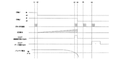
次に、図4に示すフローチャート及び図5及び図6に示すタイミングチャートを参照して露光処理について説明する。この露光処理は、カメラ全体処理のS80でバッテリチェック結果OKと判定された場合に、S82のミラーアップ直後に実行される。図5は、バルブ撮影中にバッテリーNGとなった場合を説明するタイミングチャートであり、図6は、スローシャッタ撮影中にバッテリーNGとなった場合を説明するタイミングチャートである。 Next, the exposure process will be described with reference to the flowchart shown in FIG. 4 and the timing charts shown in FIGS. This exposure process is executed immediately after the mirror up in S82 when it is determined that the battery check result is OK in S80 of the entire camera process. FIG. 5 is a timing chart for explaining a case where the battery is NG during bulb photographing, and FIG. 6 is a timing chart for explaining a case where the battery is NG during slow shutter photographing.
この処理に入ると先ず、露光開始指令をDSP13へ出力し、DSP13を介してCCD62の積分を開始させる(S200、図5及び図6;時間t1)。CCD62の積分量は、時間経過とともに増加していく。次に、露光時間を計測するためのハードタイマ(Tvカウント用タイマ)にS60で算出した適正シャッタ速度Tvをセットし(S202)、シャッター先幕マグネット43への通電をオフしてシャッター先幕を走行させる(S204、図5及び図6;時間t2)。
In this process, first, an exposure start command is output to the
続いて、S202でセットしたTvカウント用タイマをスタートさせ(S206)、適正シャッタ速度Tvがシャッターの全開時間であるシンクロ同調速度(例えば1/150)以下であるか否かをチェックする(S208)。シャッタボタンによるバルブ撮影モード及びリモコンバルブ撮影モードが設定されている場合は、シンクロ同調速度以下であると判断される。 Subsequently, the timer for Tv count set in S202 is started (S206), and it is checked whether or not the appropriate shutter speed Tv is equal to or lower than the synchro synchronization speed (for example, 1/150) that is the fully open time of the shutter (S208). . When the bulb exposure mode by the shutter button and the remote control bulb photography mode are set, it is determined that the speed is equal to or lower than the synchro synchronization speed.
『通常露光』
シンクロ同調速度よりも速いシャッター速度Tvでの露光、すなわち通常の露光では、バッテリチェック結果OKと判定された直後の露光中にバッテリー電圧が急激に低下する可能性は低いので、露光中のバッテリチェックを行なくてもよい。本実施形態では、シンクロ同調速度以下でなければ(S208;N)、Tvカウント用タイマがタイムアップするまで待機し(S288;N)、タイムアップしたらシャッター後幕マグネット44への通電をオフしてカメラ全体処理へ戻る(S288;Y、S290)。
"Normal exposure"
In exposure at a shutter speed Tv faster than the synchronization speed, that is, normal exposure, the battery voltage is unlikely to drop sharply during exposure immediately after the battery check result is determined to be OK. It is not necessary to do. In the present embodiment, if it is not less than the synchronization speed (S208; N), it waits until the timer for Tv counts up (S288; N), and when the time is up, the energization to the shutter
『長時間露光』
これに対し、シンクロ同調速度以下となるシャッタ速度Tvでの露光、つまり長時間露光では、露光時間が長いために、バッテリチェック結果OKと判定された直後であっても露光時間が経過するにつれてバッテリー電圧が低下する虞がある。よって、本実施形態では露光中も定期的にバッテリチェックを行なう。すなわち、シンクロ同調速度以下であれば(S208;Y)、15.6msタイマをスタートさせ(S210)、フラッシュトリガタイミング計測用の8.5msタイマをスタートさせる(S212)。15.6msタイマは、1/30よりも低速シャッタ速度になる場合及びバルブ撮影中にメインスイッチSWM及び蓋スイッチのオン/オフを定期的にチェックするためのハードタイマであり、この15.6msタイマの実行回数をソフトカウンタでカウントすることによって露光時間を計測する。続いて、Tvカウント用タイマがタイムアップしたか否かをチェックする(S214)。S214でフラッシュトリガタイミング8.5ms計測中にタイムアップしていると判断されるのは、適正シャッタ速度Tvが1/45〜1/150である場合である。Tvカウント用タイマがタイムアップしていれば、シャッター後幕マグネット44への通電をオフしてシャッター後幕を走行させる(S214;Y、S216)。Tvカウント用タイマがタイムアップしていなければS216をスキップする(S216;N)。そして、S212でスタートさせた8.5msタイマがタイムアップしたか否かをチェックし(S218)、該8.5msタイマがタイムアップするまでS214〜S218の処理を繰り返す(S218;N)。
"Long exposure"
On the other hand, in the exposure at the shutter speed Tv that is equal to or lower than the synchronization speed, that is, in the long time exposure, the exposure time is long. Therefore, even after the battery check result OK is determined, the battery is increased as the exposure time elapses. There is a risk of voltage drop. Therefore, in this embodiment, the battery is periodically checked even during exposure. That is, if it is equal to or lower than the synchro synchronization speed (S208; Y), a 15.6 ms timer is started (S210), and an 8.5 ms timer for flash trigger timing measurement is started (S212). The 15.6 ms timer is a hard timer for periodically checking on / off of the main switch SWM and the lid switch when the shutter speed is lower than 1/30 and during bulb photography. The 15.6 ms timer The exposure time is measured by counting the number of executions of the above by a soft counter. Subsequently, it is checked whether or not the Tv count timer has expired (S214). In S214, it is determined that the time is up during the measurement of the flash trigger timing 8.5 ms when the appropriate shutter speed Tv is 1/45 to 1/150. If the timer for Tv count is up, energization to the shutter
8.5msタイマがタイムアップしたら、外付フラッシュ22が接続されているか否か、外付フラッシュ22の充電が完了しているか否か等の外付フラッシュ発光条件がOKであるか否かをチェックし(S220)、OKであれば外付フラッシュ22へのXトリガをオンする(S220;Y、S222)。これにより外付フラッシュ22が発光する。外付フラッシュ発光条件がOKでなければS222をスキップする(S220;N)。そして、内蔵フラッシュ33が所定の発光位置までポップアップしているか否かをチェックする(S224)。内蔵フラッシュ33がポップアップしていれば、内蔵フラッシュ33の充電が完了しているか否か、内蔵フラッシュの発光が禁止されているか否か等の内蔵フラッシュ発光条件がOKが否かをチェックする(S224;Y、S226)。内蔵フラッシュ発光条件がOKであれば内蔵フラッシュ33へのトリガをオンし(S226;Y、S228)、S232へ進む。このトリガに同期して内蔵フラッシュ33は発光する。S224で内蔵フラッシュ33がポップアップしていなかった場合(S224;N)、S226で内蔵フラッシュ発光条件がOKでなかった場合(S226;N)には、そのままS232へ進む。
When the 8.5 ms timer expires, check whether the external flash emission conditions such as whether the
続いて、Tvダイアル49によりバルブ撮影モードが設定されているか否かをチェックする(S232)。バルブ撮影モードが設定されていれば(S232;Y)、リモコン撮影モードが設定されているか否かをチェックする(S234)。 Subsequently, it is checked whether or not the bulb photographing mode is set by the Tv dial 49 (S232). If the bulb shooting mode is set (S232; Y), it is checked whether or not the remote control shooting mode is set (S234).
『シャッタボタンによるバルブ撮影モード』
リモコン撮影モードが設定されていない場合は(S234;N)、シャッタボタン51によりバルブ撮影を実行している場合であり、S236へ進み、シャッタボタン51が押されている間は露光を継続する。具体的には先ず、15.6msタイマが経過するまで待機し(S236;N)、15.6msタイマが経過したら(S236;Y)、15.6msタイマの実行回数をカウントするソフトカウンタを+1加算し(S237)、15.6msタイマを再スタートさせ(S238)、バッテリー電圧を検出する(S240)。検出したバッテリー電圧値のA/D変換値は、batt-adとしてRAM11bに記憶する。続いて、バッテリー電圧値batt-adがBULBレベル未満であるか否かをチェックし(S242)、BULBレベル未満であれば(S242;Y)、露光中バッテリーNGフラグに1をセットし(S252)、露光停止指令をDSP13へ出力し(S249、図5;時間t3)、シャッター後幕マグネット44への通電を遮断してシャッター後幕を走行させる(S250、図5;時間t4)。これにより露光は強制終了される。DSP13は、CPU11から露光停止指令を入力すると(図5;時間t3)、CCD62の積分を強制終了させ、該強制終了時点までに蓄積されたCCD62の画像信号の取り込みを開始する。取り込まれた画像信号は、DSP13内で画像処理され、画像モニタ63に表示可能な撮像画像とされる。この撮影画像は、DSP13により画像記憶手段64に記憶され(図5;時間t5)、S86のメカチャージ処理後にカメラ全体処理に戻ったS94で露出アンダー警告表示アイコンと一緒に画像モニタ63のイメージLCD上に表示される。また露出アンダー警告表示アイコンは、外部表示器45(及びファインダ内表示器46)にも表示される。
"Bulb shooting mode with shutter button"
When the remote control shooting mode is not set (S234; N), it is a case where bulb shooting is being performed by the
S242でバッテリー電圧batt-adがBULBレベル未満でなかった場合は(S242;N)、画像記憶手段64用の着脱口蓋の開閉状態をチェックする蓋スイッチのスイッチ状態をチェックし(S244)、蓋が開いていなければメインスイッチSWMがオフしているか否かをチェックし(S246)、メインスイッチSWMがオフしていなければ測光スイッチSWS又はレリーズスイッチSWRのいずれかがオンしているか否かをチェックする(S246;N、S248)。測光スイッチSWS及びレリーズスイッチSWRのいずれかがオンしていれば、S236に戻る(S248;Y)。S236〜S248の処理は、バッテリー電圧値batt-adがBULBレベル未満になるか、画像記憶手段64用の着脱口蓋が開いているか、メインスイッチSWMがオフするか、又は、測光スイッチSWS及びレリーズスイッチSWRの両方がオフするまで、15.6ms毎に1回実行される。バッテリー電圧値batt-adがBULBレベル以上であっても、画像記憶手段64用の着脱口蓋が開いている場合(S242;N、S244;Y)、メインスイッチSWMがオフしている場合(S242;N、S244;N、S246;Y)、及び測光スイッチSWS及びレリーズスイッチSWRの両方がオフしている場合(S244;N、S248;N)には、そのままS249へ進み、露光停止指令をDSP13へ出力し、シャッター後幕マグネット44への通電をオフしてシャッター後幕を走行させる(S249、S250)。これにより露光完了となり、DSP13は、CCD62の積分を強制終了させて画像信号を取り込み、画像モニタ63に表示可能な撮影画像を取得して画像記憶手段64に記憶する。
If the battery voltage batt-ad is not less than the BULB level in S242 (S242; N), the switch state of the lid switch that checks the open / close state of the detachable mouth cover for the image storage means 64 is checked (S244). If it is not open, it is checked whether or not the main switch SWM is off (S246). If the main switch SWM is not off, it is checked whether either the photometry switch SWS or the release switch SWR is on. (S246; N, S248). If either the photometry switch SWS or the release switch SWR is turned on, the process returns to S236 (S248; Y). The processing of S236 to S248 is performed when the battery voltage value batt-ad becomes less than the BULB level, the attachment / detachment opening cover for the image storage means 64 is opened, the main switch SWM is turned off, or the photometric switch SWS and the release switch Runs once every 15.6 ms until both SWRs are turned off. Even when the battery voltage value batt-ad is equal to or higher than the BULB level, when the removable cover for the image storage means 64 is open (S242; N, S244; Y), when the main switch SWM is off (S242; N, S244; N, S246; Y), and when both the photometry switch SWS and the release switch SWR are off (S244; N, S248; N), the process proceeds to S249 and an exposure stop command is sent to the
『リモコンバルブ撮影モード』
S234のチェックでリモコンモードが設定されていると判断された場合は、リモコンレリーズによりバルブ撮影を行なっている場合であり、リモコン受光IC41がリモコンレリーズ信号を受信している間は露光を継続する。この場合にはS254へ進み、リモコン継続信号チェック用260msタイマをスタートさせる(S254)。この260msタイマは、リモコン装置のレリーズボタンが押されている場合に、該リモコン装置から250ms毎に1回送信されるリモコンレリーズ信号を検出するためのタイマである。続いて、バッテリー20のバッテリー電圧を検出し、該バッテリー電圧値をbatt-adとしてRAM11bに記憶し(S256)、バッテリー電圧値batt-adがBULBレベル未満であるか否かをチェックする(S258)。
Remote control bulb shooting mode
If it is determined in the check in S234 that the remote control mode is set, this is a case where bulb photography is being performed by the remote control release, and exposure is continued while the remote control
BULBレベル未満であれば(S258;Y)、露光中バッテリーNGフラグに1をセットし(S270)、露光停止指令をDSP13へ出力し(S249、図5;時間t3)、シャッター後幕マグネット44への通電を遮断してシャッター後幕を走行させる(S250、図5;時間t4)。これにより露光は強制終了される。DSP13は、露光停止指令を入力した時点(図5;時間t3)で、CCD62の積分を強制終了して画像信号の取り込みを開始する。取り込まれた露光強制終了時までの画像信号は、DSP13内で画像処理され、画像モニタ63に表示可能な撮像画像とされる。この撮影画像は、DSP13により画像記憶手段64に記憶される(図5;時間t5)。カメラ全体処理のS94では、露光強制終了されたときの撮影画像と露出アンダー警告表示アイコンとが画像モニタ63のイメージLCD上に一緒に表示される。また露出アンダー警告表示アイコンは、外部表示器45(及びファインダ内表示器46)にも表示される。
If it is less than the BULB level (S258; Y), 1 is set to the in-exposure battery NG flag (S270), an exposure stop command is output to the DSP 13 (S249, FIG. 5; time t3), and to the shutter
BULBレベル未満でなければ(S258;N)、蓋スイッチ情報に基づき画像記憶手段64用の着脱口蓋が開いているか否かをチェックし(S260)、画像記憶手段64用の着脱口蓋が開いていなければ、メインスイッチSWMがオフしているか否かをチェックする(S260;N、S262)。メインスイッチSWMがオフしていなければリモコンレリーズ継続信号を受信したか否かをチェックし(S262;N、S264)、リモコンレリーズ継続信号を受信していなければ260msタイマがタイムアップしたか否かをチェックする(S264;N、S266)。260msタイマがタイムアップしていなければ、S262へ戻り、260msタイムアップするか又はリモコンレリーズ継続信号を受信するまで待機する(S266;N)。そして、260msタイマがタイムアップしたら(S266;Y)、測光スイッチSWS又はレリーズスイッチSWRがオンしているか否かをチェックする(S268)。S268で測光スイッチSWS及びレリーズスイッチSWRのいずれか一方でもオンしている場合(S268;Y)、及び260msタイマがタイムアップする前にリモコンレリーズ継続信号を受信した場合(S264;Y)は、S254に戻り、S254〜S268の処理を繰り返す。S260で画像記録手段64用の着脱口蓋が開いていた場合(S260;Y)、S262でメインスイッチSWMがオフしていた場合(S262;Y)、及び、260msタイマが経過するまでにリモコンレリーズ継続信号を受信せず、さらに測光スイッチSWS及びレリーズスイッチSWRの両方がオンしていなかった場合(S268;Y)は、そのままS249へ進む。S249、S250では、シャッター後幕マグネット44への通電をオフしてシャッター後幕を走行させるとともに、露光停止指令をDSP13へ出力する。DSP13は、CCD62の積分を強制終了させて画像信号を取り込み、画像モニタ63に表示可能な撮影画像を取得して画像記憶手段64に記憶する。
If it is not less than the BULB level (S258; N), it is checked based on the lid switch information whether the attachment / detachment cover for the image storage means 64 is open (S260), and the attachment / detachment cover for the image storage means 64 must be opened. For example, it is checked whether or not the main switch SWM is off (S260; N, S262). If the main switch SWM is not turned off, it is checked whether or not the remote control release continuation signal has been received (S262; N, S264). If the remote control release continuation signal has not been received, it is determined whether or not the 260 ms timer has expired. A check is made (S264; N, S266). If the 260 ms timer has not expired, the process returns to S262 and waits until the 260 ms time expires or a remote control release continuation signal is received (S266; N). When the 260 ms timer expires (S266; Y), it is checked whether the photometry switch SWS or the release switch SWR is on (S268). If either the photometry switch SWS or the release switch SWR is turned on in S268 (S268; Y), or if a remote control release continuation signal is received before the 260 ms timer expires (S264; Y), S254 Returning to step S254, the processes in steps S254 to S268 are repeated. The remote control release is continued until the attachment / detachment cap for the image recording means 64 is opened in S260 (S260; Y), the main switch SWM is turned off in S262 (S262; Y), and the 260 ms timer elapses. If no signal is received and both the photometry switch SWS and the release switch SWR are not turned on (S268; Y), the process proceeds to S249 as it is. In S249 and S250, the energization of the shutter
『スローシャッター撮影』
以上はS232でバルブ撮影モードが設定されている場合の処理であるが、以下では、シャッタ速度がストロボ同調速度以下であってバルブ撮影モードが設定されていない場合(S232;N)、すなわちスローシャッター撮影での処理について説明する。この場合には、S272へ進み、Tvダイアル49で設定されたシャッタ速度又は演算された適正シャッタ速度での露光を行なう。具体的には先ず、バッテリー20のバッテリー電圧を検出し、該バッテリー電圧値のA/D変換値をbatt-adとしてRAM11bに記憶する(S272)。続いて、バッテリー電圧値batt-adがNGレベル未満であるか否かをチェックする(S274)。
"Slow shutter shooting"
The above is the processing when the bulb shooting mode is set in S232, but in the following, when the shutter speed is equal to or less than the flash synchronization speed and the bulb shooting mode is not set (S232; N), that is, the slow shutter. Processing in shooting will be described. In this case, the process proceeds to S272, and exposure is performed at the shutter speed set by the Tv dial 49 or the calculated appropriate shutter speed. Specifically, first, the battery voltage of the
NGレベル未満であれば(S274;Y)、露光中バッテリーNGフラグに1をセットし(S292)、露光停止指令をDSP13へ出力し(S292、図6;時間t3)、シャッター後幕マグネット44への通電を遮断してシャッター後幕を走行させる(S294、図6;時間t4)。これにより露光は強制終了される。DSP13は、CPU11から露光停止指令を入力した時点(図6;時間t3)で、CCD62の積分を強制終了させ、該強制終了時点までに蓄積されたCCD62の画像信号の取り込みを開始する。取り込まれた画像信号は、DSP13内で画像処理され、画像モニタ63に表示可能な撮像画像とされる。続いてCPU11は、15.6msタイマの実行回数をカウントするソフトカウンタの値及び15.6msタイマの残り時間から露光強制終了タイミングを算出し、この露光強制終了タイミングに対応する露出アンダー量を算出して(S296)、求めた露出アンダー量情報をDSP13へ送信し(S298、図6;時間t5)、カメラ全体処理に戻る。DSP13は、CPU11から露出アンダー量情報を受信すると(図6;時間t5)、撮影画像を画像記憶手段64に書き込むときに、該撮影画像のExif情報として露出アンダー量情報を一緒に記録する(図6;時間t6)。この露出アンダー量情報と撮影画像は、S292からカメラ全体処理に戻ったS106で、露出アンダー警告表示アイコンと一緒に画像モニタ63のイメージLCD上に表示される。また露出アンダー警告表示アイコンは、外部表示器45(及びファインダ内表示器46)にも表示される。
If it is less than the NG level (S274; Y), the battery NG flag during exposure is set to 1 (S292), an exposure stop command is output to the DSP 13 (S292, FIG. 6; time t3), and the shutter
NGレベル未満でなければ、画像記憶手段64用の着脱口蓋の開閉状態をチェックする蓋スイッチの状態をチェックし(S276)、蓋が開いていなければメインスイッチSWMがオフしているか否かをチェックする(S276;N、S278)。メインスイッチSWMがオフしていなければ、シャッタ時間Tvが経過したか否かをチェックする(S278;N、S280)。シャッタ時間Tvが経過していなければTvソフトカウンタを1減算し(S280;N、S282)、15.6msタイマが経過するまで待機する(S284;N)。そして15.6msタイマが経過したら(S284;Y)、15.6msタイマを再スタートさせてS272へ戻る(S286)。S272〜S286の処理は、バッテリー電圧値batt-adがNGレベル未満になるか、画像記憶手段64用の着脱口蓋が開いているか、メインスイッチSWMがオフするか、又は、シャッタ時間Tvが経過するまで、15.6ms毎に1回実行される。バッテリー電圧値batt-adがNGレベル以上であっても、画像記憶手段64用の着脱口蓋が開いている場合(S276;Y)、メインスイッチSWMがオフしている場合(S278;Y)、及びシャッタ時間Tvが経過した場合(S280;Y)は、シャッター後幕マグネット44への通電をオフしてシャッター後幕を走行させるとともに、露光停止指令をDSP13へ出力する(S249、S250)。これにより露光完了となり、DSP13は、CCD62の積分を強制終了させて画像信号を取り込み、画像モニタ63に表示可能な撮影画像を取得して画像記憶手段64に記憶する。
If it is not less than NG level, the state of the lid switch for checking the open / close state of the removable lid for the image storage means 64 is checked (S276). If the lid is not open, it is checked whether the main switch SWM is off. (S276; N, S278). If the main switch SWM is not turned off, it is checked whether or not the shutter time Tv has elapsed (S278; N, S280). If the shutter time Tv has not elapsed, the Tv soft counter is decremented by 1 (S280; N, S282) and waits until the 15.6 ms timer elapses (S284; N). When the 15.6 ms timer has elapsed (S284; Y), the 15.6 ms timer is restarted and the process returns to S272 (S286). In the processing of S272 to S286, the battery voltage value batt-ad becomes less than the NG level, the attachment / detachment cover for the image storage means 64 is opened, the main switch SWM is turned off, or the shutter time Tv elapses. Is executed once every 15.6 ms. Even when the battery voltage value batt-ad is equal to or higher than the NG level, when the detachable cover for the image storage means 64 is open (S276; Y), when the main switch SWM is off (S278; Y), and When the shutter time Tv has elapsed (S280; Y), the energization of the shutter
本実施形態は、スローシャッター撮影中にバッテリ残量不足で露光を強制終了した場合、露出アンダー警告及び露出アンダー量情報を表示して使用者に警告を促しているが、露出アンダー警告のみを表示してもよく、あるいは、露出アンダー警告及び露出アンダー量の他に、適正露出を得るための露出補正量をさらに算出して表示してもよい。露出補正量も一緒に表示されていれば、露光途中で取り込んだ撮影画像を所定の画像処理ソフトで露出補正する際に該適正補正量を参考にすることができ、使用者の手間を省くことができる。また本実施形態では、露出アンダー警告表示を点滅させることで、露光が強制終了されたこと及び露出アンダーであることを警告しているが、警告方法としては、種々の態様が可能であり、例えば電子ブザー25により警告音を発してもよい。
In this embodiment, when exposure is forcibly terminated due to insufficient battery power during slow shutter shooting, an underexposure warning and underexposure information are displayed to prompt the user, but only an underexposure warning is displayed. Alternatively, in addition to the underexposure warning and the underexposure amount, an exposure correction amount for obtaining proper exposure may be further calculated and displayed. If the exposure compensation amount is also displayed, the appropriate compensation amount can be used as a reference when performing exposure compensation on the captured image captured during exposure using the specified image processing software, saving the user's trouble. Can do. In this embodiment, the under-exposure warning is blinked to warn that the exposure has been forcibly terminated and under-exposure, but various modes are possible as the warning method, for example, A warning sound may be emitted by the
11 CPU
12 DPU
13 DSP
20 バッテリー
21 電源回路
22 外付フラッシュ
23 絞り制御回路
24 TTL調光素子
25 電子ブザー
26 測距スーパーインポーズ
27 モードダイアル
28 スイッチ手段
31 レンズCPU
32 AFIC
33 内蔵フラッシュ
34 16分割測光IC
35 ミラーモータードライバ
36 ミラーモータ
37 ミラースイッチ
38 AFモータドライバ
39 AFモータ
40 AF制御フォトインタラプタ
41 リモコン受光IC
42 EEPROM
43 シャッター先幕マグネット(ESMg1)
44 シャッター後幕マグネット(ESMg2)
45 外部表示器
46 ファインダ内表示器
47 リモコン・セルフLED
48 Avダイアル
49 Tvダイアル
50 スイッチ
51 シャッタボタン
61 フラッシュメモリ
62 CCD
63 画像モニタ
64 画像記憶手段
11 CPU
12 DPU
13 DSP
20
32 AFIC
33 Built-in
35
42 EEPROM
43 Shutter front curtain magnet (ESMg1)
44 Shutter rear curtain magnet (ESMg2)
45
48 Av dial 49
63
Claims (7)
露光中に前記バッテリー電圧がバッテリーチェックレベル未満になった場合は、該露光を強制終了し、前記プロセッサが前記画像信号の取り込みを開始すること、及び、
露光強制終了タイミングと予め設定されたシャッタ速度から適正露出に対する露出アンダー量を逆算する演算手段と、露光途中で前記プロセッサに取り込まれた画像信号に基づく撮影画像を記録するときに、前記露出アンダー量を共に記録するデータ書き込み手段とをさらに備えたこと、
を特徴とするデジタルカメラ。 Imaging means for receiving a subject image formed by a photographing lens and converting it into an electrical image signal, a processor for taking in and recording control of the image signal output from the imaging means, and a battery voltage of a driving power source being a battery In a digital camera having a battery check means for detecting whether or not it is below a check level ,
If the battery voltage falls below the battery check level during exposure, the exposure is forcibly terminated and the processor starts to capture the image signal ; and
A calculation means for calculating back the amount of underexposure for proper exposure from the forced exposure end timing and a preset shutter speed, and the amount of underexposure when recording a photographed image based on an image signal captured by the processor during exposure. And data writing means for recording
A digital camera characterized by
Priority Applications (3)
| Application Number | Priority Date | Filing Date | Title |
|---|---|---|---|
| JP2004107071A JP4355250B2 (en) | 2004-03-31 | 2004-03-31 | Digital camera |
| US11/091,433 US7542092B2 (en) | 2004-03-31 | 2005-03-29 | Digital camera with a battery checking device |
| DE102005014788A DE102005014788B4 (en) | 2004-03-31 | 2005-03-31 | digital camera |
Applications Claiming Priority (1)
| Application Number | Priority Date | Filing Date | Title |
|---|---|---|---|
| JP2004107071A JP4355250B2 (en) | 2004-03-31 | 2004-03-31 | Digital camera |
Publications (3)
| Publication Number | Publication Date |
|---|---|
| JP2005295183A JP2005295183A (en) | 2005-10-20 |
| JP2005295183A5 JP2005295183A5 (en) | 2007-04-19 |
| JP4355250B2 true JP4355250B2 (en) | 2009-10-28 |
Family
ID=35034298
Family Applications (1)
| Application Number | Title | Priority Date | Filing Date |
|---|---|---|---|
| JP2004107071A Expired - Fee Related JP4355250B2 (en) | 2004-03-31 | 2004-03-31 | Digital camera |
Country Status (3)
| Country | Link |
|---|---|
| US (1) | US7542092B2 (en) |
| JP (1) | JP4355250B2 (en) |
| DE (1) | DE102005014788B4 (en) |
Families Citing this family (13)
| Publication number | Priority date | Publication date | Assignee | Title |
|---|---|---|---|---|
| US8995715B2 (en) * | 2010-10-26 | 2015-03-31 | Fotonation Limited | Face or other object detection including template matching |
| US20100066890A1 (en) * | 2005-12-06 | 2010-03-18 | Panasonic Corporation | Digital camera |
| CN103647893B (en) * | 2005-12-06 | 2017-05-17 | 松下电器产业株式会社 | Digital camera, camera body, camera system and control method for the digital camera |
| US8223242B2 (en) * | 2005-12-06 | 2012-07-17 | Panasonic Corporation | Digital camera which switches the displays of images with respect to a plurality of display portions |
| JP4643437B2 (en) * | 2005-12-27 | 2011-03-02 | 株式会社東芝 | Information processing device |
| JP4643453B2 (en) * | 2006-01-10 | 2011-03-02 | 株式会社東芝 | Information processing apparatus and moving picture decoding method for information processing apparatus |
| JP5161443B2 (en) * | 2006-08-11 | 2013-03-13 | ペンタックスリコーイメージング株式会社 | camera |
| TWI410124B (en) * | 2008-10-02 | 2013-09-21 | Asia Optical Co Inc | An image recording apparatus and control method thereof |
| KR101141854B1 (en) * | 2009-12-30 | 2012-05-08 | 삼성전자주식회사 | Method and apparatus for driving camera |
| US8774591B2 (en) * | 2011-10-28 | 2014-07-08 | Canon Kabushiki Kaisha | Content management apparatus, recording apparatus, operation apparatus, content management system, and control methods thereof |
| JPWO2020129304A1 (en) * | 2018-12-19 | 2021-11-25 | パナソニックIpマネジメント株式会社 | Imaging device |
| US11836886B2 (en) | 2021-04-15 | 2023-12-05 | MetaConsumer, Inc. | Systems and methods for capturing and processing user consumption of information |
| US11688035B2 (en) * | 2021-04-15 | 2023-06-27 | MetaConsumer, Inc. | Systems and methods for capturing user consumption of information |
Family Cites Families (22)
| Publication number | Priority date | Publication date | Assignee | Title |
|---|---|---|---|---|
| JP3498389B2 (en) * | 1994-11-04 | 2004-02-16 | カシオ計算機株式会社 | Electronic still camera |
| JPH08179396A (en) | 1994-12-21 | 1996-07-12 | Nikon Corp | Exposure controller for camera |
| JP3411440B2 (en) * | 1996-02-18 | 2003-06-03 | 株式会社リコー | camera |
| JP3203188B2 (en) * | 1996-09-03 | 2001-08-27 | 三洋電機株式会社 | Electronic still camera |
| JP3340646B2 (en) | 1996-09-19 | 2002-11-05 | 旭光学工業株式会社 | Voltage application stop timing control device for electro-developing recording medium |
| JP2000115588A (en) | 1998-10-08 | 2000-04-21 | Canon Inc | Image pickup device, control method thereof and storage medium |
| JP4436506B2 (en) * | 1999-12-08 | 2010-03-24 | オリンパス株式会社 | Electronic camera device |
| US7113204B2 (en) * | 2000-02-04 | 2006-09-26 | Canon Kabushiki Kaisha | Image sensing apparatus, control method of image sensing apparatus, and computer program product |
| US20020005907A1 (en) * | 2000-04-25 | 2002-01-17 | Alten Brett G. | Remote control unit with visual display device for cameras and video recorders |
| US6982747B2 (en) * | 2000-05-18 | 2006-01-03 | Canon Kabushiki Kaisha | Notification of operating status in image sensing system |
| JP4423764B2 (en) * | 2000-07-25 | 2010-03-03 | 株式会社ニコン | Electronic camera |
| JP2002344794A (en) * | 2001-05-18 | 2002-11-29 | Fuji Photo Film Co Ltd | Digital camera |
| JP4593834B2 (en) * | 2001-07-02 | 2010-12-08 | 富士フイルム株式会社 | Digital camera and system |
| JP2003110948A (en) * | 2001-07-27 | 2003-04-11 | Sanyo Electric Co Ltd | Imaging apparatus |
| JP3539414B2 (en) * | 2001-09-25 | 2004-07-07 | 株式会社日立製作所 | Information recording device |
| JP2003110899A (en) * | 2001-09-27 | 2003-04-11 | Ricoh Co Ltd | Cradle device for digital camera |
| JP2003219219A (en) * | 2002-01-23 | 2003-07-31 | Sanyo Electric Co Ltd | Digital camera |
| JP3632668B2 (en) | 2002-02-18 | 2005-03-23 | ミノルタ株式会社 | Digital camera |
| US7123155B2 (en) * | 2002-04-05 | 2006-10-17 | Hewlett-Packard Development Company, L.P. | Operational mode-based battery monitoring for a battery-powered electronic device |
| JP2004037822A (en) * | 2002-07-03 | 2004-02-05 | Fuji Photo Film Co Ltd | Battery remaining quantity warning device |
| US20050062878A1 (en) * | 2003-03-26 | 2005-03-24 | Nikon Corporation | Power system and camera |
| US20040257463A1 (en) * | 2003-06-17 | 2004-12-23 | Goris Andrew C. | User interface for digital camera having nonvolatile memory for storing intermediate data for advanced processing and capable of slowing, delaying and/or suspending advanced processing during low battery conditions |
-
2004
- 2004-03-31 JP JP2004107071A patent/JP4355250B2/en not_active Expired - Fee Related
-
2005
- 2005-03-29 US US11/091,433 patent/US7542092B2/en not_active Expired - Fee Related
- 2005-03-31 DE DE102005014788A patent/DE102005014788B4/en not_active Expired - Fee Related
Also Published As
| Publication number | Publication date |
|---|---|
| US7542092B2 (en) | 2009-06-02 |
| JP2005295183A (en) | 2005-10-20 |
| DE102005014788B4 (en) | 2012-08-09 |
| DE102005014788A1 (en) | 2005-10-20 |
| US20050219406A1 (en) | 2005-10-06 |
Similar Documents
| Publication | Publication Date | Title |
|---|---|---|
| US7542092B2 (en) | Digital camera with a battery checking device | |
| US7773148B2 (en) | Power system having a battery unit that calculate cumulative work volume value | |
| JP2002344794A (en) | Digital camera | |
| JP2005184508A (en) | Imaging device and control method therefor | |
| JP2003232987A (en) | Focusing device | |
| JP2007104108A (en) | Imaging apparatus, emission luminance control method and program | |
| JP2009058837A (en) | Imaging apparatus, imaging method and program | |
| JP4358942B2 (en) | Interchangeable lens camera system and interchangeable lens | |
| JP2000347286A (en) | Camera used both for silver salt photography and electronic image pickup | |
| JP2005292740A (en) | Electronic camera | |
| JP2829919B2 (en) | Flash photography system for image signal recorder | |
| JPH0516585Y2 (en) | ||
| JP2004023538A (en) | Photographing device | |
| JP4288414B2 (en) | Digital camera that estimates the number of possible shots | |
| JP2016110000A (en) | Imaging device | |
| JP4243799B2 (en) | Digital camera and system, and electronic device system. | |
| JP2000122119A (en) | Camera | |
| JP2006106201A (en) | Camera | |
| JP2000101886A (en) | Camera system and photographing medium unit used for the same | |
| JP2000350090A (en) | Camera | |
| JPH10319490A (en) | Camera with liquid crystal finder | |
| JP4168600B2 (en) | Imaging apparatus and exposure correction method | |
| JP2003309758A (en) | Camera main body and camera | |
| JP2008270987A (en) | Image pickup device and its control method | |
| JP2004350187A (en) | Digital camera |
Legal Events
| Date | Code | Title | Description |
|---|---|---|---|
| A621 | Written request for application examination |
Free format text: JAPANESE INTERMEDIATE CODE: A621 Effective date: 20070306 |
|
| A521 | Request for written amendment filed |
Free format text: JAPANESE INTERMEDIATE CODE: A523 Effective date: 20070307 |
|
| RD04 | Notification of resignation of power of attorney |
Free format text: JAPANESE INTERMEDIATE CODE: A7424 Effective date: 20070621 |
|
| A711 | Notification of change in applicant |
Free format text: JAPANESE INTERMEDIATE CODE: A712 Effective date: 20080501 |
|
| A131 | Notification of reasons for refusal |
Free format text: JAPANESE INTERMEDIATE CODE: A131 Effective date: 20090428 |
|
| A521 | Request for written amendment filed |
Free format text: JAPANESE INTERMEDIATE CODE: A523 Effective date: 20090626 |
|
| TRDD | Decision of grant or rejection written | ||
| A01 | Written decision to grant a patent or to grant a registration (utility model) |
Free format text: JAPANESE INTERMEDIATE CODE: A01 Effective date: 20090721 |
|
| A01 | Written decision to grant a patent or to grant a registration (utility model) |
Free format text: JAPANESE INTERMEDIATE CODE: A01 |
|
| A61 | First payment of annual fees (during grant procedure) |
Free format text: JAPANESE INTERMEDIATE CODE: A61 Effective date: 20090731 |
|
| R150 | Certificate of patent or registration of utility model |
Ref document number: 4355250 Country of ref document: JP Free format text: JAPANESE INTERMEDIATE CODE: R150 Free format text: JAPANESE INTERMEDIATE CODE: R150 |
|
| FPAY | Renewal fee payment (event date is renewal date of database) |
Free format text: PAYMENT UNTIL: 20120807 Year of fee payment: 3 |
|
| S111 | Request for change of ownership or part of ownership |
Free format text: JAPANESE INTERMEDIATE CODE: R313111 |
|
| FPAY | Renewal fee payment (event date is renewal date of database) |
Free format text: PAYMENT UNTIL: 20120807 Year of fee payment: 3 |
|
| R350 | Written notification of registration of transfer |
Free format text: JAPANESE INTERMEDIATE CODE: R350 |
|
| FPAY | Renewal fee payment (event date is renewal date of database) |
Free format text: PAYMENT UNTIL: 20120807 Year of fee payment: 3 |
|
| FPAY | Renewal fee payment (event date is renewal date of database) |
Free format text: PAYMENT UNTIL: 20130807 Year of fee payment: 4 |
|
| S533 | Written request for registration of change of name |
Free format text: JAPANESE INTERMEDIATE CODE: R313533 |
|
| R350 | Written notification of registration of transfer |
Free format text: JAPANESE INTERMEDIATE CODE: R350 |
|
| LAPS | Cancellation because of no payment of annual fees |