JP2005184508A - Imaging device and control method therefor - Google Patents
Imaging device and control method therefor Download PDFInfo
- Publication number
- JP2005184508A JP2005184508A JP2003422951A JP2003422951A JP2005184508A JP 2005184508 A JP2005184508 A JP 2005184508A JP 2003422951 A JP2003422951 A JP 2003422951A JP 2003422951 A JP2003422951 A JP 2003422951A JP 2005184508 A JP2005184508 A JP 2005184508A
- Authority
- JP
- Japan
- Prior art keywords
- face
- area
- light emission
- image
- dimming
- Prior art date
- Legal status (The legal status is an assumption and is not a legal conclusion. Google has not performed a legal analysis and makes no representation as to the accuracy of the status listed.)
- Withdrawn
Links
Images


Landscapes
- Stroboscope Apparatuses (AREA)
- Studio Devices (AREA)
Abstract
Description
本発明は、静止画像や動画像を撮像、記録、再生する撮像装置及びその制御方法に関するものである。 The present invention relates to an imaging apparatus that captures, records, and reproduces still images and moving images, and a control method thereof.
従来、固体メモリ素子を有するメモリカードを記憶媒体として、静止画像や動画像を記録し、また損沖億媒体に記憶されている画像データを再生できる電子カメラ等の画像処理装置が市販されており、カラー液晶パネル等の電子ファインダを備える電子カメラも販売されている。 2. Description of the Related Art Conventionally, image processing apparatuses such as electronic cameras that can record still images and moving images and play back image data stored on a lossless medium using a memory card having a solid-state memory element as a storage medium are commercially available. An electronic camera equipped with an electronic viewfinder such as a color liquid crystal panel is also sold.
これらの電子カメラでは、暗所での撮影の補助光として、ストロボを内蔵したり、或は電子カメラ本体に別体のストロボを装着できるように構成されており、夜間など暗い場所でも鮮明な電子写真を撮ることが可能となっている。 These electronic cameras are designed to have a built-in strobe as auxiliary light for shooting in the dark or to be able to attach a separate strobe to the main body of the electronic camera. It is possible to take pictures.
このような従来の電子カメラのストロボ装置では、レリーズ時の本撮像の前にプリ発光を行い、プリ撮像画像から被写体の輝度レベルと、適正調光レベルの差を求め、その差に応じて、実際の撮像時の発光量を決定して撮像を行うようになっている(例えば、特許文献1参照)。 In such a strobe device of a conventional electronic camera, pre-flash is performed before actual imaging at the time of release, and the difference between the luminance level of the subject and the appropriate light control level is obtained from the pre-captured image, and according to the difference, Imaging is performed by determining the light emission amount at the time of actual imaging (see, for example, Patent Document 1).
この際の調光範囲は、一般的に測距領域を中心として設定される。 The light control range at this time is generally set around the distance measurement area.
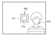
図10は、撮影画面における測距領域912と調光領域911との関係を説明する図である。
FIG. 10 is a diagram illustrating the relationship between the
同図では、測距領域912と被写体910とが重なっているので、測距領域912を中心とした調光領域911を基に調光制御を行っても、問題のない鮮明な画像を撮像することができる。しかし、例えば被写体910に合焦した(ピント合わせを行った)後に、カメラによる撮像範囲を移動させて図11の構図を変えた場合に、被写体910と測距領域912とが合致しなくなる。このような状態で、この測距領域912を中心にして調光制御を行うと被写体910がいない領域920で調光制御が行われるので、露出オーバな画像が撮像されてしまう虞がある。
In the same figure, since the
これを回避するためには、例えば図12に示す様に、測距領域912を被写体910が存在している領域に設定してAF動作を行えばよいが、一般的には、測距領域912の位置の選択するよりも、測距領域912は図11のように画面中央のままにしてAF動作を行い、この合焦後に構図を変更することが一般的に行われる。従って、被写体910と調光領域911とが合致せずに露出オーバな画像となってしまうという問題があった。
In order to avoid this, for example, as shown in FIG. 12, the AF area operation may be performed by setting the
そこで、AF前に撮影画像から被写体910の顔を検出し、この検出された被写体の顔領域に重みをつけて露出制御したり(例えば、特許文献2参照)、調光制御したりする(例えば、特許文献3参照)技術が提案されている。このような構成であれば、合焦後に構図を変更する作業を行わずとも、常に被写体の顔に合焦させることが可能となる。
しかしながら、例えば輝度が十分でない状況(例えば、夜景を背景として人物を撮影する場合)では、撮影画像から人物の顔の検出を精度良く行うことは難しい。人物の顔検出方法として、所定以上の大きさを有する肌色領域を顔領域とみなす方法や、輝度情報から顔の輪郭や目の形状を検出して顔領域とみなす方法があるが、どちらの場合も暗闇では検出精度が低下することは否めない。 However, for example, in a situation where the luminance is not sufficient (for example, when a person is photographed against a night view), it is difficult to accurately detect the person's face from the photographed image. There are two methods for detecting a human face: a method in which a skin color area with a size greater than or equal to a predetermined size is considered as a face area, and a method in which the face contour and eye shape are detected from luminance information and considered as a face area. However, the detection accuracy cannot be denied in the dark.
本発明は上記問題点に鑑みてなされたもので、被写体と予め設定されている調光領域が合致していない場合でも、適正なストロボ撮影画像が得られる撮像装置及びその制御方法を提供することを目的とする。 The present invention has been made in view of the above problems, and provides an imaging apparatus capable of obtaining an appropriate flash image even when a subject and a preset light control area do not match, and a control method thereof. With the goal.
プリ発光の撮像画面から被写体の顔位置を検出し、予め設定されている調光領域と検知された顔領域とが異なる場合に、顔領域を中心とした領域で調光制御を行う撮像装置及びその制御方法を提供する。 An imaging device that detects a face position of a subject from a pre-flash imaging screen, and performs dimming control in an area centered on the face area when the preset dimming area and the detected face area are different; The control method is provided.
本発明の撮像装置は以下のような構成を備える。即ち、
撮影時におけるメイン発光前にプリ発光を行う撮像装置であって、
被写体との距離を測定する測距手段と、
被写体を含む撮像画像内にストロボの調光制御領域を、前記測距手段により測定された前記距離に応じて設定する調光領域設定手段と、
プリ発光による撮像画像を基に、前記撮像画像内における顔領域を検出する顔領域検出手段と、
前記顔領域検出手段により検出された顔領域に応じて前記調光制御領域を決定する決定手段と、
前記決定手段で決定された前記調光制御領域における前記プリ発光による測光値に応じてメイン発光量を演算する演算手段と、
前記演算手段により演算された前記メイン発光量に基づいてストロボを制御して撮影を行うように制御する制御手段とを有することを特徴とする。
The imaging device of the present invention has the following configuration. That is,
An imaging device that performs pre-flash before main flash during shooting,
Ranging means for measuring the distance to the subject;
A dimming area setting means for setting a dimming control area of a strobe in a captured image including a subject according to the distance measured by the distance measuring means;
A face area detecting means for detecting a face area in the captured image based on a captured image by pre-emission;
Determining means for determining the dimming control area according to the face area detected by the face area detecting means;
A calculation means for calculating a main light emission amount according to a photometric value by the pre-light emission in the light control area determined by the determination means;
Control means for controlling the strobe to perform photographing based on the main light emission amount calculated by the calculating means.
また本発明の撮像装置の制御方法は以下のような工程を備える。即ち、
撮影時におけるメイン発光前にプリ発光を行う撮像装置における制御方法であって、
被写体との距離を測定する測距工程と、
被写体を含む撮像画像内にストロボの調光制御領域を、前記測距工程で測定された前記距離に応じて設定する調光領域設定工程と、
プリ発光による撮像画像を基に、前記撮像画像内における顔領域を検出する顔領域検出工程と、
前記顔位置検出工程で検出された顔領域に応じて前記調光制御領域を決定する決定工程と、
前記決定工程で決定された前記調光制御領域における前記プリ発光による測光値に応じてメイン発光量を演算する演算工程と、
前記演算工程で演算された前記メイン発光量に基づいてストロボを制御して撮影を行うように制御する制御工程とを有することを特徴とする。
Moreover, the control method of the imaging device of the present invention includes the following steps. That is,
A control method in an imaging device that performs pre-flash before main flash at the time of shooting,
A ranging process for measuring the distance to the subject;
A dimming area setting step for setting a dimming control area of a strobe in a captured image including a subject according to the distance measured in the ranging process;
A face area detection step of detecting a face area in the captured image based on a captured image by pre-emission;
A determining step of determining the dimming control region according to the face region detected in the face position detecting step;
A calculation step of calculating a main light emission amount according to a photometric value by the pre-light emission in the light control region determined in the determination step;
And a control step of controlling the strobe to perform photographing based on the main light emission amount calculated in the calculation step.
本発明によれば、被写体の輝度が十分に得られない状況での撮影であっても、高い精度で被写体の顔領域を検出することができ、この検出した顔領域に基づいて適正なストロボ制御を行うことが可能となる。 According to the present invention, it is possible to detect a face area of a subject with high accuracy even when shooting in a situation where the brightness of the subject cannot be sufficiently obtained, and to perform appropriate strobe control based on the detected face area. Can be performed.
以下、添付図面を参照して本発明の好適な実施の形態を詳しく説明する。 Hereinafter, preferred embodiments of the present invention will be described in detail with reference to the accompanying drawings.
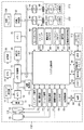
図1は、本発明の実施の形態に係る電子カメラ(画像処理装置)100の構成を示すブロック図である。 FIG. 1 is a block diagram showing a configuration of an electronic camera (image processing apparatus) 100 according to an embodiment of the present invention.
図において、10は撮影レンズ、12はシャッタ、14は光学像を電気信号に変換する撮像素子、16は撮像素子14のアナログ信号出力をディジタル信号に変換するA/D変換器である。タイミング発生部18は、撮像素子14、A/D変換器16、D/A変換器26にクロック信号や制御信号を供給して、それらの動作を制御している。このタイミング発生部18は、メモリ制御部22及びシステム制御部50により制御されている。画像処理部20は、A/D変換器16からのデータ或いはメモリ制御部22からのデータに対して所定の画素補間処理や色変換処理を行う。また、この画像処理部20は、撮像した画像データを用いて所定の演算処理を行い、それから得られた演算結果に基づいてシステム制御部50がシャッタ制御部40、測距制御部42に対する制御を実行する、TTL(スルー・ザ・レンズ)方式のAF(オートフォーカス)処理、AE(自動露出)処理、EF(ストロボプリ発光)処理を行っている。また画像処理部20は、撮像した画像データを用いて所定の演算処理を行い、得られた演算結果に基づいてTTL方式のAWB(オートホワイトバランス)処理も行っている。更に、その撮像した画像データから、目、口のエッジを特徴を抽出し、人間の顔を検出する顔検出処理も実行している。
In the figure, 10 is a photographing lens, 12 is a shutter, 14 is an image sensor that converts an optical image into an electrical signal, and 16 is an A / D converter that converts an analog signal output of the
メモリ制御部22は、A/D変換器16、タイミング発生部18、画像処理部20、画像表示用メモリ24、D/A変換器26、メモリ30、圧縮/伸長部32を制御する。これにより、A/D変換器16でA/D変換されたデータは画像処理部20、メモリ制御部22を介して、或いはA/D変換器16でA/D変換されたデータが直接メモリ制御部22を介して、画像表示用メモリ24或いはメモリ30に書き込まれる。
The
画像表示用メモリ24は画像表示部26に表示するデータを記憶しており、この画像表示用メモリ24に記憶されているデータはD/A変換器26を介してTFT,LCD等の画像表示部28に出力されて表示される。この画像表示部28により、撮像した画像データを逐次表示すれば、電子ファインダとして機能を実現できる。また画像表示部28は、システム制御部50の指示により任意に表示をオン/オフすることが可能であり、表示をオフにした場合は、この画像処理装置100の電力消費を大幅に低減できる。メモリ30は、撮影した静止画像や動画像を格納するためのメモリで、所定枚数の静止画像や所定時間分の動画像を格納するのに十分な記憶量を備えている。これにより、複数枚の静止画像を連続して撮影する連射撮影やパノラマ撮影の場合にも、高速かつ大量の画像書き込みをメモリ30に対して行うことが可能となる。また、このメモリ30はシステム制御部50の作業領域としても使用することが可能である。圧縮/伸長部32は、例えば適応離散コサイン変換(ADCT)等により画像データを圧縮及び伸長することができ、メモリ30に格納された画像データを読み込んで圧縮処理を行ったり、或いは圧縮された画像データを読み込んで伸長処理を行い、その処理を終えたデータをメモリ30に書き込むことができる。
The
シャッタ制御部40は、シャッタ12を制御する。測距制御部42は、撮影レンズ10のフォーカシングを制御する。測距制御部43は、撮影レンズ10のフォーカシング位置から被写体の距離を検出する。ズーム制御部44は、撮影レンズ10のズーミングを制御する。絞り制御部46は絞り102の動作を制御する。ストロボユニット48は、AF補助光の投光機能、ストロボ調光機能も有する。シャッタ制御部40、測距制御部42はTTL方式を用いて制御されており、撮像した画像データを画像処理部20によって演算した演算結果に基づき、システム制御部50がシャッタ制御部40、絞り制御部46、測距制御部42に対して制御を行う。
The
システム制御部50は、この画像処理装置100全体の動作を制御している。メモリ52は、このシステム制御部50の動作用の定数、変数、プログラム等を記憶している。表示部54は、システム制御部50でのプログラムの実行に応じて、文字、画像、音声等を用いて動作状態やメッセージ等を表示する液晶表示ユニット、スピーカ等を含んでいる。この表示部54は、画像処理装置100の操作部70の近辺の視認し易い位置に単数或いは複数個所設置され、例えばLCDやLED、発音素子等の組み合わせにより構成されている。また、この表示部54は、その一部の機能が光学ファインダ104内に設置されている。この表示部54の表示内容の内、LCD等に表示するものとしては、シングルショット/連写撮影表示、セルフタイマ表示、圧縮率表示、記録画素数表示、記録枚数表示、残撮影可能枚数表示、シャッタスピード表示、絞り値表示、露出補正表示、ストロボ表示、赤目緩和表示、マクロ撮影表示、ブザー設定表示、時計用電池残量表示、電池残量表示、エラー表示、複数桁の数字による情報表示、記憶媒体200及び210の着脱状態表示、通信I/F動作表示、日付け・時刻表示等がある。また、この表示部54の表示内容の内、光学ファインダ104に表示するものとしては、合焦表示、手振れ警告表示、ストロボ充電表示、シャッタスピード表示、絞り値表示、露出補正表示、等がある。
The
不揮発メモリ56は、電気的に消去及び記録が可能なメモリであり、例えばEEPROM等が用いられる。モードダイアル60、シャッタスイッチ62,64、画像表示ON/OFFスイッチ66、クイックレビューON/OFFスイッチ68及び操作部70は、システム制御部50の各種の動作指示を入力するための操作ユニットであり、スイッチやダイアル、タッチパネル、視線検知によるポインティング、音声認識装置等の単数或いは複数の組み合わせで構成される。
The
次にここで、これらの操作ユニットを具体的に説明する。 Next, these operation units will be specifically described here.
モードダイアルスイッチ60は、電源オフ、自動撮影モード、撮影モード、パノラマ撮影モード、再生モード、マルチ画面再生及び消去モード、PC接続モード等の各機能モードを切り替え設定することができる。シャッタスイッチ(SW1)62は、不図示のシャッターボタンの操作途中でオンとなり、AF(オートフォーカス)処理、AE(自動露出)処理、AWB(オートホワイトバランス)処理等の動作開始を指示する。シャッタスイッチ(SW2)64は、不図示のシャッタボタンの操作完了でオンとなり、ストロボ撮影モードの場合は、ストロボユニット48の発光制御、撮像素子14から読み出した信号をA/D変換器16、メモリ制御部22を介してメモリ30に画像データとして書き込む露光処理、画像処理部20やメモリ制御部22での演算を用いた現像処理、メモリ30から画像データを読み出し、圧縮/伸長部32で圧縮を行い、記憶媒体200或いは210に画像データを書き込む記録処理という一連の処理の動作開始を指示する。画像表示ON/OFFスイッチ66は、画像表示部28への画像表示のON/OFFを設定することができる。この機能により、光学ファインダ104を用いて撮影を行う際に、TFT,LCD等からなる画像表示部28への電流供給を遮断することにより、省電力を図ることが可能となる。クイックレビューON/OFFスイッチ68は、撮影直後に、その撮影した画像データを自動再生するクイックレビュー機能を設定する。尚、本実施の形態では、特に画像表示部28をオフにした場合におけるクイックレビュー機能を設定する機能を備えるものとする。操作部70は、各種ボタンやタッチパネル等を有し、これらスイッチやボタンには、メニューボタン、セットボタン、マクロボタン、マルチ画面再生改ページボタン、ストロボ設定ボタン、単写/連写/セルフタイマー切り替えボタン、メニュー移動+(プラス)ボタン、メニュー移動−(マイナス)ボタン、再生画像移動+(プラス)ボタン、再生画像−(マイナス)ボタン、撮影画質選択ボタン、露出補正ボタン、日付/時間設定ボタン等がある。
The
電源制御部80は、電池検出部、DC−DCコンバータ、通電するブロックを切り替えるスイッチ部等を備えており、電池の装着の有無、電池の種類、電池残量の検出を行い、その検出結果及びシステム制御部50の指示に基づいてDC−DCコンバータを制御し、必要な電圧を必要な期間、記憶媒体を含む各部へ供給する。82,84はコネクタ、電源86は、アルカリ電池やリチウム電池等の一次電池やNiCd電池やNiMH電池、Li電池等の二次電池、ACアダプタ等を備える。
The
90及び94は、メモリカードやハードディスク等の記憶媒体とのインタフェース、92及び96はメモリカードやハードディスク等の記憶媒体と接続を行うコネクタである。記憶媒体着脱検知部98は、コネクタ92及び或いは96に記憶媒体200或いは210が装着されているか否かを検知する。
尚、本実施の形態では、記憶媒体を取り付けるインターフェース及びコネクタを2系統有するものとして説明している。もちろん、この記憶媒体を取り付けるインターフェース及びコネクタは、単数或いは複数、いずれの系統数を備える構成としても構わない。また、異なる規格のインターフェース及びコネクタを組み合わせて備える構成としても構わない。インターフェース及びコネクタとしては、PCMCIAカードやCF(コンパクフラッシュ)カード等の規格に準拠したものを用いて構成して構わない。 In the present embodiment, it is assumed that there are two systems of interfaces and connectors for attaching a storage medium. Of course, the interface and connector to which this storage medium is attached may have a single or plural number of systems. Moreover, it is good also as a structure provided with combining the interface and connector of a different standard. The interface and the connector may be configured using a PCMCIA card, a CF (Compact Flash) card, or the like that conforms to a standard.
更に、インタフェース90及び94、そしてコネクタ92及び96をPCMCIAカードやCF(コンパクトフラッシュ(登録商標))カード等の規格に準拠したものを用いて構成した場合、LANカードやモデムカード、USBカード、IEEE1394カード、P1284カード、SCSIカード、PHS等の通信カード、等の各種通信カードを接続することにより、他のコンピュータやプリンタ等の周辺機器との間で画像データや画像データに付属した管理情報を転送し合うことができる。
Further, when the
絞り102は、シャッタ12との組み合わせで撮像素子14への露光量を決定している。光学ファインダ104は、画像表示部28による電子ファインダ機能を使用すること無しに、光学ファインダのみを用いて撮影を行うことが可能である。また、この光学ファインダ104には、表示部54の一部の機能、例えば、合焦表示、手振れ警告表示、ストロボ充電表示、シャッタスピード表示、絞り値表示、露出補正表示などが設置されている。通信部110は、RS232CやUSB,IEEE1394,P1284,SCSI、モデム、LAN、無線通信、等の各種通信機能を有する。アンテナ(コネクタ)112は、通信部110により画像処理装置100を他の機器と接続するもので、有線による接続の場合はコネクタ、無線通信の場合はアンテナである。記憶媒体200は、メモリカードやハードディスク等の記憶媒体である。この記憶媒体200は、半導体メモリや磁気ディスク等から構成される記憶部202、画像処理装置100とのインタフェース204、画像処理装置100と接続を行うコネクタ206を備えている。また記憶媒体210はメモリカードやハードディスク等の記憶媒体で、この記憶媒体210も半導体メモリや磁気ディスク等から構成される記憶部212、画像処理装置100とのインタフェース214、画像処理装置100と接続を行うコネクタ216を備えている。
The
図2は、本実施の形態に係るストロボユニット48をより詳しく説明するブロック図である。
FIG. 2 is a block diagram for explaining the
DC/DCコンバータ300は、電源86から出力される比較的低い電圧を300V程度の高電圧に昇圧している。コンデンサ301は、このDC/DCコンバータ300の出力に並列に接続されて発光エネルギーを充電している。分圧抵抗302,303は、コンデンサ301の充電電圧をモニタするために,その充電電圧を低電圧に分圧している。Xe管等の発光部305は、トリガ部304からのトリガ電圧により励起されて発光する。電流遮断素子306は、Xe管305の発光を制御するための素子で、例えばIGBTなどである。受光素子307は例えばフォトダイオードなどで構成され、Xe管305の発光量をモニタしている。圧縮積分部308は、受光素子307から出力される光電流を入力して増幅し、対数圧縮を行いXe管305の発光量を検出している。発光量コンパレータ309は、Xe管305の発光量が所定量以上かどうかを検出して、その検出結果を出力している。また310〜314はシステムコントローラ50との接続端子である。
The DC /
端子310は、Xe管305の発光開始/停止を制御する発光制御端子である。端子311は、トリガ部304を制御するためのトリガ制御信号を入力するトリガ制御端子である。端子312は、コンデンサ301の電圧をモニタするための電圧モニタ端子である。端子313は、発光量を制御するためのコンパレータ309のコンパレート電圧端子、端子314はコンパレータの出力端子である。
The terminal 310 is a light emission control terminal that controls the start / stop of light emission of the
以下、図3乃至図8のフローチャートを参照して、本実施の形態に係る電子カメラの動作を説明する。尚、この処理を実行するプログラム(図9の900)はメモリ52に記憶されており、システム制御部50の制御の下に実行される。尚、このメモリ52のメモリマップ例を図9に示す。図9において、907は、後述するように顔領域が検出されたときに、その顔位置データ及びその顔領域の画像データの平均輝度とを含む1つの顔領域に対する顔データを示している。従って、1つの画像内に複数の顔領域が検出された場合は、その顔領域の数だけ、この顔データ907が記憶されることになる。そして、908は、複数の顔が存在する場合、それら顔領域の平均輝度を求めて格納するエリアである。
Hereinafter, the operation of the electronic camera according to the present embodiment will be described with reference to the flowcharts of FIGS. A program for executing this processing (900 in FIG. 9) is stored in the
図3及び図4は本実施の形態に係る電子カメラ(画像処理装置)におけるメイン処理ルーチンでの動作を説明するフローチャートである。 3 and 4 are flowcharts for explaining the operation in the main processing routine in the electronic camera (image processing apparatus) according to the present embodiment.
この処理は、例えば電池交換後などの電源投入により開始され、まずステップS101で、システム制御部50は、メモリ52の各種フラグや制御変数等を初期化し、ステップS102で、画像表示部28の画像表示をオフ状態に初期設定する。次にステップS103で、モードダイアル60の設定位置を判定し、モードダイアル60が電源オフに設定されていたならばステップS105に進み、各表示部の表示を終了状態に変更し、フラグや制御変数等を含む必要なパラメータや設定値、設定モードを不揮発性メモリ56に記録し、電源制御手段80により画像表示部28を含む画像処理装置100各部の不要な電源を遮断する等の所定の終了処理を行った後、再びステップS103に戻る。
This process is started when the power is turned on, for example after battery replacement. First, in step S101, the
またステップS103で、モードダイアル60が撮影モードに設定されていればステップS106に進むが、その他のモードに設定されていればステップS104に進んで、そのモードダイアル60で選択されたモードに応じた処理を実行し、その処理を終えるとステップS103に戻る。
In step S103, if the
撮影モードが設定されている場合はステップS106に進み、電源制御部80からの信号に基づいて、電池等により構成される電源86の残容量や動作情況が画像処理装置100の動作に問題があるか否かを判断する。問題があると判断するとステップS108に進み、表示部54を用いて、画像や音声により所定の警告表示を行い、その後、ステップS103に戻る。
If the shooting mode is set, the process proceeds to step S106, and the remaining capacity and operation status of the
ステップS106で、電源86に問題が無いと判断するとステップS107に進み、記憶媒体200或いは210の動作状態が画像処理装置100の動作、特に記憶媒体に対する画像データの記録再生動作に問題があるか否かを判断し、問題があると判断すると前述のステップS108に進み、表示部54を用いて、画像や音声により所定の警告表示を行った後にステップS103に戻る。
If it is determined in step S106 that there is no problem with the
ステップS107で問題がないと判断するとステップS109に進み、表示部54を用いて、画像や音声により画像処理装置100の各種設定状態のUI表示を行う。尚、画像表示部28の画像表示がオンであったならば、画像表示部28も用いて画像や音声により画像処理装置100の各種設定状態のUI表示を行ってもよい。こうしてユーザによる各種設定がなされる。
If it is determined in step S107 that there is no problem, the process proceeds to step S109, and the
次にステップS110で、クイックレビューオン/オフスイッチ68の状態を調べ、クイックレビューがオンに設定されているとステップS111に進んで、メモリ52のクイックレビューフラグ901をオンに設定する。一方、クイックレビューオン/オフスイッチ68で、クイックレビューオフに設定されていればステップS112に進み、メモリ52のクイックレビューフラグ901をオフにする。尚、このクイックレビューフラグ901は、システム制御部50の内部メモリ或いはメモリ52に記憶されているが、ここでは図9に示すように、メモリ52に設定されている場合で説明する。これは他のフラグに関しても同様である。
Next, in step S110, the state of the quick review on / off switch 68 is checked. If the quick review is set to on, the process proceeds to step S111, and the
次にステップS113に進み、画像表示オン/オフスイッチ66の設定状態を調べ、画像表示がオンに設定されていればステップS114に進み、メモリ52の画像表示フラグ902をオンに設定し、次にステップS115で、画像表示部28の画像表示をオン状態に設定する。更に、ステップS116で、撮像した画像データを逐次表示するスルー表示状態に設定してステップS119(図4)に進む。このスルー表示状態では、撮像素子14、A/D変換器16、画像処理部20、メモリ制御部22を介して、画像表示用メモリ24に逐次書き込まれたデータを、メモリ制御部22、D/A変換器26を介して画像表示部28により逐次表示することにより、電子ファインダ機能を実現している。
In step S113, the setting state of the image display on / off
一方、ステップS113で、画像表示オン/オフスイッチ66が画像表示オフに設定されているとステップS117に進み、画像表示フラグ902をオフにするとともに、ステップS118で、画像表示部28の画像表示をオフ状態に設定してステップS119に進む。この画像表示オフの場合は、画像表示部28による電子ファインダ機能を使用せず、光学ファインダ104を用いて撮影する。この場合、電力消費量の大きい画像表示部28やD/A変換器26等の消費電力を削減することが可能となる。尚、画像表示フラグ902は、システム制御部50の内部メモリ或いはメモリ52に記憶されている。
On the other hand, if the image display on / off
ステップS119では、シャッタスイッチ(SW1)62が押されているかどうかを調べ、押されていなければステップS103に戻るが、シャッタスイッチ(SW1)62が押されたならばステップS120に進み、システム制御部50の内部メモリ或いはメモリ52に記憶されている画像表示フラグ902がオンに設定されているかをみる。オンに設定されていればステップS121に進み、画像表示部28の表示状態をフリーズ表示状態に設定してステップS122に進む。このフリーズ表示状態では、撮像素子14、A/D変換器16、画像処理部20、メモリ制御部22を介した画像表示用メモリ24の画像データの書き換えを禁止し、最後に書き込まれた画像データを、メモリ制御部22、D/A変換器26を介して画像表示部28により表示することにより、フリーズした映像を光学ファインダ104に表示している。
In step S119, it is checked whether or not the shutter switch (SW1) 62 has been pressed. If not, the process returns to step S103. If the shutter switch (SW1) 62 has been pressed, the process proceeds to step S120, and the system control unit. It is checked whether the
ステップS120で、画像表示フラグ902がオフであればステップS122に進む。ステップS122では、測距処理を行って撮影レンズ10の焦点を被写体に合わせ、更に測光処理を行って絞り値及びシャッタ速度を決定する。この測光処理では、必要であればストロボの設定も行う。尚、この測距及び測光処理S122の詳細は図5のフローチャートを参照して詳しく後述する。
If the
ステップS122で、測距及び測光処理を終えるとステップS123に進み、システム制御部50の内部メモリ或いはメモリ52に記憶される画像表示フラグ902の状態を判定する。ここで画像表示フラグ902がオンに設定されているとステップS124に進み、画像表示部28の表示状態をスルー表示状態に設定してステップS125に進む。尚、ステップS124でのスルー表示状態は、ステップS116でのスルー状態と同じ動作である。
When the distance measurement and photometry processing is completed in step S122, the process proceeds to step S123, and the state of the
次にステップS125で、シャッタスイッチ(SW2)64が押されずに、更にシャッタスイッチ(SW1)62も解除されるとステップS103(図3)に戻る。 Next, in step S125, if the shutter switch (SW1) 62 is also released without pressing the shutter switch (SW2) 64, the process returns to step S103 (FIG. 3).
一方、ステップS125でシャッタスイッチ(SW2)64が押されるとステップS127に進み、システム制御部50の内部メモリ或いはメモリ52に記憶される画像表示フラグ902がオンかどうかを判定し、画像表示フラグ902がオンであればステップS128に進み、画像表示部28の表示状態を固定色表示状態に設定してステップS129に進む。この固定色表示状態では、撮像素子14、A/D変換器16、画像処理部20、メモリ制御部22を介して画像表示用メモリ24に書き込まれた撮影画像データの代わりに、差し替えた固定色の画像データを、メモリ制御部22、D/A変換器26を介して画像表示部28に表示する。こうして固定色の映像を電子ファインダ104に表示している。
On the other hand, when the shutter switch (SW2) 64 is pressed in step S125, the process proceeds to step S127, where it is determined whether the
またステップS127で、画像表示フラグ902がオフであればステップS129に進む。このステップS129では、撮像素子14、A/D変換器16、画像処理部20、メモリ制御部22を介して、或いはA/D変換器16から直接メモリ制御部22を介して、撮影した画像データをメモリ30に書き込む露光処理、及び、メモリ制御部22、そして必要に応じて画像処理部20を用いて、メモリ30に書き込まれた画像データを読み出して各種処理を行う現像処理からなる撮影処理を実行する。
If the
この撮影処理(S129)の詳細は図6及び図7を参照して用いて後述する。 Details of the photographing process (S129) will be described later with reference to FIGS.
こうしてステップS129の撮影処理が実行されるとステップS130に進み、システム制御部50の内部メモリ或いはメモリ52に記憶される画像表示フラグ902がオンかどうかを判定し、画像表示フラグ902がオンであればステップS133に進み、クイックレビュー表示を行う。この場合は、撮影中も画像表示部28が電子ファインダとして常に表示された状態であり、撮影直後のクイックレビュー表示も行われる。
When the photographing process of step S129 is executed in this way, the process proceeds to step S130, where it is determined whether or not the
ステップS130で、画像表示フラグ902がオフであればステップS131に進み、システム制御部50の内部メモリ或いはメモリ52に記憶されるクイックレビューフラグ901がオンかどうかをみる。クイックレビューフラグ901がオンであればステップS132に進み、画像表示部28の画像表示をオン状態に設定してクイックレビュー表示を行い、その後、ステップS134に進む。
If it is determined in step S130 that the
またステップS130で画像表示フラグ902がオフで、ステップS131でクイックレビューフラグ901もオフであれば、画像表示部28をオフ状態のままでステップS134に進む。この場合は、撮影を行った後でも画像表示部28は消えたままであり、クイックレビュー表示も行われない。これは、光学ファインダ104を用いて撮影を続ける場合のように、撮影直後の撮影画像の確認が不要で、画像表示部28の電子ファインダ機能を使用せずに省電力を重視する使用方法である。
If the
ステップS134では、メモリ30に書き込まれた撮影した画像データを読み出して、メモリ制御部22、及び必要に応じて画像処理部20を用いて各種画像処理を実行し、及び、圧縮/伸長部32を用いて設定したモードに応じた画像圧縮処理を行った後、記憶媒体200或いは210へ、圧縮した画像データの書き込みを行う記録処理を実行する。この記録処理(S134)の詳細は図8のフローチャートを参照して詳しく後述する。
In step S134, the captured image data written in the
ステップS134の記録処理が終了した後、ステップS135で、シャッタスイッチ(SW2)64が押された状態かどうかを調べ、そうであればステップS136に進み、システム制御部50の内部メモリ或いはメモリ52に記憶される連写フラグ903の状態を判定する。ここで連写フラグ903がオンであれば、連続して撮影を行うためにステップS129に進み、次の映像の撮影を行う。ステップS136で、連写フラグ903がオンでなければステップS137に進み、シャッタースイッチ(SW2)64が放されるまでステップS135、S136の処理を繰り返す。
After the recording process in step S134 is completed, in step S135, it is checked whether the shutter switch (SW2) 64 has been pressed. If so, the process proceeds to step S136, and the
このように本実施の形態によれば、撮影直後にクイックレビュー表示を行う動作設定状態の場合に、記録処理(S134)が終了した際にシャッタスイッチ(SW2)が押された状態であればシャッタスイッチ(SW2)64が放されるまで画像表示部28におけるクイックレビュー表示を継続する。これにより、撮影画像の確認を入念に行うことができる。
As described above, according to the present embodiment, in the operation setting state in which the quick review display is performed immediately after shooting, the shutter is pressed if the shutter switch (SW2) is pressed when the recording process (S134) is completed. The quick review display on the
こうしてステップS134の記録処理の後、直ぐにシャッタスイッチ(SW2)64がオフされた場合、或いは、ステップS134の記録処理の後、シャッタスイッチ(SW2)を押し続けてクイックレビュー表示を継続して撮影画像の確認を行った後にシャッタースイッチ(SW2)をオフにした場合はステップS135からステップS137に進み、所定のミニマムレビュー時間が経過するのを待ってステップS138に進む。ステップS138では、画像表示フラグ902がオンかどうかを調べ、オンであればステップS139に進み、画像表示部28の表示状態をスルー表示状態に設定してステップS141に進む。これにより、画像表示部28でのクイックレビュー表示によって撮影画像を確認した後に、次の撮影のために撮像した画像データを逐次表示するスルー表示状態にすることが出来る。またステップS138で、画像表示フラグ902がオフであればステップS140に進み、画像表示部28の画像表示をオフ状態に設定してステップS141に進む。これにより、画像表示部28でのクイックレビュー表示によって撮影画像を確認した後に、省電力のために画像表示部28の機能を停止して、電力消費量の大きい画像表示部28やD/A変換器26等の消費電力を削減することが可能となる。
In this way, when the shutter switch (SW2) 64 is turned off immediately after the recording process of step S134, or after the recording process of step S134, the shutter switch (SW2) is kept pressed and the quick review display is continued to be taken. When the shutter switch (SW2) is turned off after confirming the above, the process proceeds from step S135 to step S137, and waits for a predetermined minimum review time to elapse, and then proceeds to step S138. In step S138, it is checked whether the
ステップS141では、シャッタスイッチ(SW1)62がオンされた状態かどうかを調べ、そうであればステップS125に進んで次の撮影に備える。またステップS141で、シャッタスイッチ(SW1)62がオフされている場合は、一連の撮影動作を終えてステップS103(図3)に戻る。 In step S141, it is checked whether the shutter switch (SW1) 62 is turned on. If so, the process proceeds to step S125 to prepare for the next shooting. If it is determined in step S141 that the shutter switch (SW1) 62 has been turned off, the series of photographing operations is terminated and the process returns to step S103 (FIG. 3).
図5は、図4のステップS122における測距及び測光処理の詳細を示すフローチャートである。 FIG. 5 is a flowchart showing details of the distance measurement and photometry processing in step S122 of FIG.
まずステップS201で、撮像素子14から電荷信号を読み出し、A/D変換器16を介してデジタルデータに変換し、そのデジタルデータを画像処理部20に入力する。この入力された画像データを用いて、画像処理部20はTTL方式のAE(自動露出)処理、EF(ストロボプリ発光)処理、AF(オートフォーカス)処理に用いる所定の演算を行っている。尚、ここでの各処理は、撮影した全画素数の内の必要に応じた特定の部分を必要個所分切り取って抽出し演算に用いている。これにより、TTL方式のAE,EF,AWB,AFの各処理において、中央重点モード、平均モード、評価モードの各モード等の異なるモード毎に最適な演算を行うことが可能となる。
First, in step S <b> 201, a charge signal is read from the
ステップS201における画像処理部20での演算結果を用いて、ステップS202で露出(AE)が適正と判断されナイトステップS203に進み、絞り制御部46及び、撮像素子14の電子シャッタの組み合わせでAE制御を行う。このAE制御で得られた測定データ905(図9)を用いて、ステップS204で、ストロボが必要か否かを判断し、ストロボが必要であればステップS205に進み、ストロボフラグ904をセットし、ストロボ48を充電してステップS201に進む。
Using the calculation result in the
ステップS202で、露出(AE)が適正と判断したならばステップS206に進み、測定データ905及び或いは設定パラメータ906をシステム制御部50の内部メモリ或いはメモリ52に記憶する(図9ではメモリ52に記憶した例を示す)。そして画像処理部20での演算結果及びAE制御で得られた測定データを用いて、ホワイトバランス(AWB)が適正かどうかを判断し、適正でないと判断するとステップS207に進み、画像処理部20を用いて色処理のパラメータを調節してAWB制御を行ってステップS201に進む。
If it is determined in step S202 that the exposure (AE) is appropriate, the process proceeds to step S206, and the
こうしてステップS206で、ホワイトバランス(AWB)が適正と判断するとステップS208に進み、メモリ52の測定データ905及び或いは設定パラメータ906をシステム制御部50の内部メモリ或いはメモリ52に記憶する。そしてAE制御及びAWB制御で得られた測定データ905を用いて、測距(AF)が合焦であるかどうかを判断する。合焦でないときはステップS209に進み、測距制御部42を用いてAF制御を行ってステップS201に進む。こうしてステップS208で、測距(AF)が合焦と判断すると、測定データ905及び或いは設定パラメータ906をシステム制御部50の内部メモリ或いはメモリ52に記憶し、この測距及び測光処理を終了する。
When it is determined in step S206 that the white balance (AWB) is appropriate, the process proceeds to step S208, and the
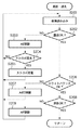
図6及び図7は、図4のS129における撮影処理の詳細を示すフローチャートである。 6 and 7 are flowcharts showing details of the photographing process in S129 of FIG.
前述の測距及び測光処理で得られて、システム制御部50の内部メモリ或いはメモリ52に記憶されている測光データ905に従い、絞り制御部46にて絞り値をセットするとともに、シャッタ制御部40によってシャッタ12を開放して撮像素子10を露光する(S301及びS302)。
The aperture value is set by the
次にステップS303で、ストロボフラグ904によりストロボ48が必要か否かを判断し、ストロボが必要な場合はステップS304に進み、所定の発光量でストロボユニット80をプリ発光させる。このプリ発光の光量は、レンズ10の絞り値と距離検出部43で検出された被写体までの距離と、設定された撮像素子14の感度とに基づいて決定される。ステップS305では、測光データ905に従って撮像素子14の露光終了を待ち、露光終了のタイミングになるとステップS306で、シャッタ12を閉じる。そしてステップS307で、撮像素子14から電荷信号を読み出し、A/D変換器16、画像処理部20、メモリ制御部22を介して、或いはA/D変換器16から直接メモリ制御部22を介して、撮影画像のデータをメモリ30に書き込む。
Next, in step S303, it is determined whether or not the
次にステップS308に進み、設定された撮影モードに応じて、フレーム処理を行う必要があるかどうかを判定し、フレーム処理を行う必要があればステップS309に進み、メモリ制御部22、及び必要に応じて画像処理部20を用いて、メモリ30に書き込まれた画像データを読み出して垂直加算処理を実行し、次にステップS310で、色処理を順次行った後、ステップS311で、顔検知処理を行う。この画像処理部20による顔検知処理は、前述した様に、撮像した画像データのなかから、目、口のエッジを特徴を抽出することにより人の顔位置を検知し、目、口を包含する顔の輪郭を検出して、その重心位置を求めるとともに、輪郭内の領域の輝度(画像信号レベル)を算出する。尚、この顔検知処理は、レンズ10のフォーカシング位置より、距離検出部43で検出した距離と、レンズの焦点距離とから人の顔の大きさを予測し、検出精度を高めている。
Next, the process proceeds to step S308, where it is determined whether it is necessary to perform frame processing according to the set shooting mode. If it is necessary to perform frame processing, the process proceeds to step S309, where the
次にステップS312では、ステップS311で検知された顔の数を判定し、その数が「0」の場合はステップS313に進み、「1」の場合はステップS314に、複数の場合はステップS318に分岐する。顔面検知がなされなかった場合、即ち、検知された顔の数が「0」の場合はステップS313で、予め設定されている通りに、測距点と合致した調光領域内の輝度(画像信号レベル)平均値を算出してステップS321(図7)に進む。 Next, in step S312, the number of faces detected in step S311 is determined. If the number is “0”, the process proceeds to step S313. If “1”, the process proceeds to step S314. If more than one, the process proceeds to step S318. Branch. If face detection has not been performed, that is, if the number of detected faces is “0”, in step S313, as previously set, the luminance (image signal in the dimming area that matches the distance measuring point). Level) average value is calculated, and the process proceeds to step S321 (FIG. 7).
検出された顔の数が「1」の場合、ステップS314で、その検出された顔の位置が予め設定された調光領域と一致するかどうかを判定し、一致する場合はステップS315に進み、検出された顔面の面積に応じて調光領域を修正する。一致しない場合はステップS316に分岐し、その検出された顔位置(図9の顔位置データに基づく領域)を新たな調光領域に設定し、検出された顔の面積に応じて調光領域を設定する。こうしてステップS315或はS316を実行するとステップS317に進み、ステップS315或はステップS316で設定された調光領域内の輝度(画像信号レベル)の平均値(図9の顔領域の平均輝度)を算出してステップS321(図7)に進む。 If the number of detected faces is “1”, in step S314, it is determined whether or not the position of the detected face matches a preset dimming area. If they match, the process proceeds to step S315. The dimming area is corrected according to the detected face area. If they do not match, the process branches to step S316, the detected face position (area based on the face position data in FIG. 9) is set as a new dimming area, and the dimming area is set according to the detected face area. Set. When step S315 or S316 is executed in this way, the process proceeds to step S317, and the average value of the luminance (image signal level) in the light control region set in step S315 or step S316 (average luminance of the face region in FIG. 9) is calculated. Then, the process proceeds to step S321 (FIG. 7).
一方、ステップS312の顔の検出処理で、複数の顔が検出された場合はステップS318(図7)に進み、それら検出された各顔の顔位置データと、各顔の領域に応じた複数の調光領域を設定する。次にステップS319で、各顔領域(調光領域内)の輝度(画像信号レベル)の平均値を算出して図9に示す各顔の平均輝度907に記憶する。更にステップS320で、これら検出された複数の調光領域の平均輝度を更に平均化して図9の複数の顔の平均輝度エリア908に格納してステップS321に進む。
On the other hand, if a plurality of faces are detected in the face detection process in step S312, the process proceeds to step S318 (FIG. 7), and a plurality of face position data for each detected face and a plurality of faces corresponding to each face region are detected. Set the dimming area. Next, in step S319, the average value of the brightness (image signal level) of each face area (in the light control area) is calculated and stored in the
こうしてステップS321で、調光領域内の輝度(画像信号レベル)が適正輝度(適正信号レベル)となる本発光量(実際の撮影時の発光量)を演算する。例えば、プリ発光によるプリ撮像の画像信号レベルが適正レベルである場合は、プリ発光と同じ発光量で良く、また例えば、プリ撮像の画像信号レベルが1段階下回っている場合は、プリ発光の2倍の発光量に設定する等の処理を行う。 In this way, in step S321, the main light emission amount (light emission amount at the time of actual photographing) at which the luminance (image signal level) in the dimming area becomes appropriate luminance (appropriate signal level) is calculated. For example, when the image signal level of pre-imaging by pre-emission is an appropriate level, the same amount of light emission as that of pre-emission is sufficient. For example, when the image signal level of pre-emission is one step lower, Processing such as setting the light emission amount to double is performed.
次にステップS322で、本撮像のために、再度シャッタ制御部40によってシャッタ12を開放し、ステップS323で、撮像素子10を露光する。そしてステップS324に進み、ステップS321で求めた本発光量で、ストロボユニット80を発光させる。
Next, in step S322, the
ステップS325では、測光データに従って撮像素子14の露光が終了までの時間を待ち、ステップS326で、シャッタ12を閉じる。そしてステップS327で、撮像素子14から電荷信号を読み出し、A/D変換器16、画像処理部20、メモリ制御部22を介して、或いはA/D変換器16から直接メモリ制御部22を介して、メモリ30に撮影画像のデータを書き込む。ステップS328で、設定された撮影モードに応じて、フレーム処理を行う必要があるかどうかを判断し、フレーム処理を行う必要があればステップS329に進み、メモリ制御部22、そして必要に応じて画像処理部20を用いて、メモリ30に書き込まれた画像データを読み出して垂直加算処理を実行し、ステップS330で、色処理を順次行った後、その処理を終えた画像データをメモリ30に書き込む。そしてステップS331で、メモリ30から画像データを読み出し、メモリ制御部22を介して画像表示用メモリ24に表示画像データの転送を行う。こうして一連の処理を終えたならば、撮影処理ルーチン(S129)を終了する。
In step S325, the time until the exposure of the
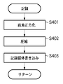
図8は、図4のS134における撮像記録処理の詳細を示すフローチャートである。 FIG. 8 is a flowchart showing details of the imaging recording process in S134 of FIG.
まずステップS401で、メモリ制御部22、そして必要に応じて画像処理部20を用いて、メモリ30に書き込まれた撮影画像データを読み出して撮像素子の縦横画素比率を「1:1」に補間する画素正方化処理を行い、その処理を終えた画像データをメモリ30に書き込む。次にステップS402で、メモリ30に書き込まれた画像データを読み出して、設定したモードに応じた画像圧縮処理を圧縮/伸長部32により行った後、ステップS403で、インターフェース90或いは94、コネクタ92或いは96を介して、メモリカードやコンパクトストロボカード等の記憶媒体200或いは210へ圧縮した画像データの書き込みを行う。こうして記憶媒体への書き込みが終わったならば、記録処理ルーチンS134を終了する。
First, in step S401, the captured image data written in the
尚、本実施の形態では、画像処理装置100にて検出された顔位置と、その大きさに応じて、調光領域を設定したが、誤検出の可能性もあるので、被写体までの距離を検出する距離検出部40で検出された、被写体距離、プリ発光光量、絞り値、ISO感度を基に、顔の反射率を25%とした場合の適正となる輝度値を演算し、その輝度値と比較して、所望の範囲内であれば、検出された顔位置をそのまま調光領域として用い、その範囲外であるならば誤検出と判断して、予め設定された調光領域を用いるか、もしくは画面上の最も輝度の高い領域を調光領域として用いてもよい。
In this embodiment, the dimming area is set according to the face position detected by the
また、この際、前述の被写体距離に応じた適正輝度値と、画面内の高輝度領域を比較し、所望の輝度範囲よりも高い場合は、ガラスや鏡などの異常反射領域として、調光領域から排除することにより、より正確に調光領域を設定することが可能になる。また、顔検知の際は、被写体の色相を認識することにより、より正確に顔の領域を検出することが可能となる。 At this time, the appropriate brightness value according to the subject distance is compared with the high brightness area in the screen, and if it is higher than the desired brightness range, the dimming area is used as an abnormal reflection area such as glass or a mirror. By eliminating from the above, it becomes possible to set the light control region more accurately. In the face detection, the face area can be detected more accurately by recognizing the hue of the subject.
(その他の実施例)
なお本発明は、複数の機器(例えばホストコンピュータ、インターフェース機器、リーダ、プリンタなど)から構成されるシステムに適用しても、一つの機器からなる装置(例えば、複写機、ファクシミリ装置など)に適用してもよい。
(Other examples)
Note that the present invention can be applied to a system (for example, a copier, a facsimile machine, etc.) composed of a single device even if it is applied to a system composed of a plurality of devices (for example, a host computer, interface device, reader, printer, etc.). May be.
また、本発明の目的は、前述した実施の形態の機能を実現するソフトウェアのプログラムコードを記録した記憶媒体(または記録媒体)を、システム或は装置に供給し、そのシステムあるいは装置のコンピュータ(またはCPUやMPU)が記憶媒体に格納されたプログラムコードを読み出し実行することによっても達成される。この場合、記憶媒体から読み出されたプログラムコード自体が前述した実施形態の機能を実現することになり、そのプログラムコードを記憶した記憶媒体は本発明を構成することになる。また、コンピュータが読み出したプログラムコードを実行することにより、前述した実施形態の機能が実現されるだけでなく、そのプログラムコードの指示に基づき、コンピュータで稼働しているオペレーティングシステム(OS)などが実際の処理の一部または全部を行い、その処理によって前述した実施形態の機能が実現される場合も含まれる。 Another object of the present invention is to supply a storage medium (or recording medium) in which a program code of software that realizes the functions of the above-described embodiments is recorded to a system or apparatus, and to perform a computer (or a computer) This can also be achieved by the CPU and MPU) reading and executing the program code stored in the storage medium. In this case, the program code itself read from the storage medium realizes the functions of the above-described embodiments, and the storage medium storing the program code constitutes the present invention. Further, by executing the program code read by the computer, not only the functions of the above-described embodiments are realized, but also an operating system (OS) running on the computer is actually executed based on the instruction of the program code. This includes a case where part or all of the processing is performed and the functions of the above-described embodiments are realized by the processing.
さらに、記憶媒体から読み出されたプログラムコードが、コンピュータに挿入された機能拡張カードやコンピュータに接続された機能拡張ユニットに備わるメモリに書込まれた後、そのプログラムコードの指示に基づき、その機能拡張カードや機能拡張ユニットに備わるCPUなどが実際の処理の一部または全部を行い、その処理によって前述した実施形態の機能が実現される場合も含まれる。例えば、PC上のドライバでこれらの処理を行う場合が、これに相当することは言うまでもない。 Furthermore, after the program code read from the storage medium is written into a memory provided in a function expansion card inserted into the computer or a function expansion unit connected to the computer, the function is determined based on the instruction of the program code. The case where the CPU of the expansion card or the function expansion unit performs part or all of the actual processing and the functions of the above-described embodiments are realized by the processing is also included. For example, it goes without saying that this processing is performed by a driver on a PC.
Claims (14)
被写体との距離を測定する測距手段と、
被写体を含む撮像画像内にストロボの調光制御領域を、前記測距手段により測定された前記距離に応じて設定する調光領域設定手段と、
プリ発光による撮像画像を基に、前記撮像画像内における顔領域を検出する顔領域検出手段と、
前記顔領域検出手段により検出された顔領域に応じて前記調光制御領域を決定する決定手段と、
前記決定手段で決定された前記調光制御領域における前記プリ発光による測光値に応じてメイン発光量を演算する演算手段と、
前記演算手段により演算された前記メイン発光量に基づいてストロボを制御して撮影を行うように制御する制御手段と、
を有することを特徴とする撮像装置。 An imaging device that performs pre-flash before main flash during shooting,
Ranging means for measuring the distance to the subject;
A dimming area setting means for setting a dimming control area of a strobe in a captured image including a subject according to the distance measured by the distance measuring means;
A face area detecting means for detecting a face area in the captured image based on a captured image by pre-emission;
Determining means for determining the dimming control area according to the face area detected by the face area detecting means;
A calculation means for calculating a main light emission amount according to a photometric value by the pre-light emission in the light control area determined by the determination means;
Control means for controlling the strobe to perform shooting based on the main light emission amount calculated by the calculating means;
An imaging device comprising:
前記決定手段は、前記比較手段により一致しないとされると、前記調光領域設定手段により設定された調光制御領域を前記顔位置検出手段により検出された顔領域に合わせるように決定することを特徴とする請求項1乃至4のいずれか1項に記載の撮像装置。 Comparing means for comparing whether the dimming control area set by the dimming area setting means and the face area detected by the face position detecting means match,
The determining means determines that the dimming control area set by the dimming area setting means is matched with the face area detected by the face position detecting means when it does not match by the comparing means. The imaging apparatus according to claim 1, wherein the imaging apparatus is characterized.
被写体との距離を測定する測距工程と、
被写体を含む撮像画像内にストロボの調光制御領域を、前記測距工程で測定された前記距離に応じて設定する調光領域設定工程と、
プリ発光による撮像画像を基に、前記撮像画像内における顔領域を検出する顔領域検出工程と、
前記顔位置検出工程で検出された顔領域に応じて前記調光制御領域を決定する決定工程と、
前記決定工程で決定された前記調光制御領域における前記プリ発光による測光値に応じてメイン発光量を演算する演算工程と、
前記演算工程で演算された前記メイン発光量に基づいてストロボを制御して撮影を行うように制御する制御工程と、
を有することを特徴とする制御方法。 A control method in an imaging device that performs pre-flash before main flash at the time of shooting,
A ranging process for measuring the distance to the subject;
A dimming area setting step for setting a dimming control area of a strobe in a captured image including a subject according to the distance measured in the ranging process;
A face area detection step of detecting a face area in the captured image based on a captured image by pre-emission;
A determining step of determining the dimming control region according to the face region detected in the face position detecting step;
A calculation step of calculating a main light emission amount according to a photometric value by the pre-light emission in the light control region determined in the determination step;
A control step for controlling the strobe to perform shooting based on the main light emission amount calculated in the calculation step;
A control method characterized by comprising:
前記決定工程では、前記比較工程で一致しないとされると、前記調光領域設定工程で設定された調光制御領域を前記顔位置検出工程で検出された顔領域に合わせるように決定することを特徴とする請求項7乃至10のいずれか1項に記載の制御方法。 Further comprising a comparison step for comparing whether or not the dimming control region set in the dimming region setting step matches the face region detected in the face position detection step;
If it is determined in the determination step that they do not coincide with each other in the comparison step, the dimming control region set in the dimming region setting step is determined to be matched with the face region detected in the face position detection step. The control method according to claim 7, wherein the control method is any one of claims 7 to 10.
Priority Applications (1)
| Application Number | Priority Date | Filing Date | Title |
|---|---|---|---|
| JP2003422951A JP2005184508A (en) | 2003-12-19 | 2003-12-19 | Imaging device and control method therefor |
Applications Claiming Priority (1)
| Application Number | Priority Date | Filing Date | Title |
|---|---|---|---|
| JP2003422951A JP2005184508A (en) | 2003-12-19 | 2003-12-19 | Imaging device and control method therefor |
Publications (2)
| Publication Number | Publication Date |
|---|---|
| JP2005184508A true JP2005184508A (en) | 2005-07-07 |
| JP2005184508A5 JP2005184508A5 (en) | 2006-12-28 |
Family
ID=34783652
Family Applications (1)
| Application Number | Title | Priority Date | Filing Date |
|---|---|---|---|
| JP2003422951A Withdrawn JP2005184508A (en) | 2003-12-19 | 2003-12-19 | Imaging device and control method therefor |
Country Status (1)
| Country | Link |
|---|---|
| JP (1) | JP2005184508A (en) |
Cited By (21)
| Publication number | Priority date | Publication date | Assignee | Title |
|---|---|---|---|---|
| JP2007259237A (en) * | 2006-03-24 | 2007-10-04 | Fujifilm Corp | Apparatus and method for photographing |
| JP2007310026A (en) * | 2006-05-16 | 2007-11-29 | Ricoh Co Ltd | Image recording method and device |
| JP2007336355A (en) * | 2006-06-16 | 2007-12-27 | Fujifilm Corp | Photographing device |
| JP2008079158A (en) * | 2006-09-22 | 2008-04-03 | Fujifilm Corp | Digital camera and control method thereof |
| JP2008079143A (en) * | 2006-09-22 | 2008-04-03 | Fujifilm Corp | White balance correction method and imaging apparatus |
| JP2008087140A (en) * | 2006-10-05 | 2008-04-17 | Toyota Motor Corp | Speech recognition robot and control method of speech recognition robot |
| JP2008219880A (en) * | 2007-02-08 | 2008-09-18 | Canon Inc | Image pickup device and image pickup method |
| JP2009253899A (en) * | 2008-04-10 | 2009-10-29 | Sony Corp | Imaging device |
| US7796831B2 (en) | 2005-12-27 | 2010-09-14 | Samsung Electronics Co., Ltd. | Digital camera with face detection function for facilitating exposure compensation |
| KR20100104050A (en) * | 2009-03-16 | 2010-09-29 | 삼성전자주식회사 | Method and apparatus for controlling flash emission |
| JP2011013459A (en) * | 2009-07-02 | 2011-01-20 | Panasonic Corp | Image pickup apparatus and mobile phone equipped therewith |
| US7894715B2 (en) | 2008-03-31 | 2011-02-22 | Canon Kabushiki Kaisha | Image pickup apparatus, camera system, and control method for image pickup apparatus |
| US7924343B2 (en) | 2006-09-29 | 2011-04-12 | Fujifilm Corporation | Photographing apparatus and exposure control method |
| JP2011078143A (en) * | 2011-01-19 | 2011-04-14 | Fujifilm Corp | Photographing apparatus, face detecting method thereof and image recording method |
| CN103871091A (en) * | 2014-04-04 | 2014-06-18 | 南京大学 | Night scene map making method for point element distribution characteristic expression |
| KR20160036230A (en) * | 2014-09-25 | 2016-04-04 | 엘지전자 주식회사 | Method for controlling mobile terminal and mobile terminal |
| WO2018194043A1 (en) * | 2017-04-17 | 2018-10-25 | ソニー株式会社 | Imaging device, method for controlling imaging device, and processing device |
| US10999523B2 (en) | 2018-02-02 | 2021-05-04 | Canon Kabushiki Kaisha | Image pickup apparatus, method for controlling image pickup apparatus, and storage medium for controlling flash photography when a still image is imaged |
| US11115603B2 (en) | 2018-04-04 | 2021-09-07 | Canon Kabushiki Kaisha | Image pickup apparatus that reduces time required for light control processing and method of controlling same |
| US11394890B2 (en) | 2019-02-21 | 2022-07-19 | Canon Kabushiki Kaisha | Image pickup apparatus that controls flash photography, control method therefor, and storage medium |
| JP7129196B2 (en) | 2018-04-04 | 2022-09-01 | キヤノン株式会社 | IMAGING DEVICE, CONTROL METHOD AND PROGRAM THEREOF |
-
2003
- 2003-12-19 JP JP2003422951A patent/JP2005184508A/en not_active Withdrawn
Cited By (29)
| Publication number | Priority date | Publication date | Assignee | Title |
|---|---|---|---|---|
| US7796831B2 (en) | 2005-12-27 | 2010-09-14 | Samsung Electronics Co., Ltd. | Digital camera with face detection function for facilitating exposure compensation |
| US7570883B2 (en) | 2006-03-24 | 2009-08-04 | Fujifilm Corporation | Image pickup method and apparatus with ISO sensitivity setting variable |
| JP2007259237A (en) * | 2006-03-24 | 2007-10-04 | Fujifilm Corp | Apparatus and method for photographing |
| JP4542058B2 (en) * | 2006-03-24 | 2010-09-08 | 富士フイルム株式会社 | Imaging apparatus and imaging method |
| JP2007310026A (en) * | 2006-05-16 | 2007-11-29 | Ricoh Co Ltd | Image recording method and device |
| JP2007336355A (en) * | 2006-06-16 | 2007-12-27 | Fujifilm Corp | Photographing device |
| JP4663607B2 (en) * | 2006-09-22 | 2011-04-06 | 富士フイルム株式会社 | Digital camera and control method thereof |
| JP2008079143A (en) * | 2006-09-22 | 2008-04-03 | Fujifilm Corp | White balance correction method and imaging apparatus |
| JP2008079158A (en) * | 2006-09-22 | 2008-04-03 | Fujifilm Corp | Digital camera and control method thereof |
| US7924343B2 (en) | 2006-09-29 | 2011-04-12 | Fujifilm Corporation | Photographing apparatus and exposure control method |
| JP2008087140A (en) * | 2006-10-05 | 2008-04-17 | Toyota Motor Corp | Speech recognition robot and control method of speech recognition robot |
| JP2008219880A (en) * | 2007-02-08 | 2008-09-18 | Canon Inc | Image pickup device and image pickup method |
| US7894715B2 (en) | 2008-03-31 | 2011-02-22 | Canon Kabushiki Kaisha | Image pickup apparatus, camera system, and control method for image pickup apparatus |
| JP2009253899A (en) * | 2008-04-10 | 2009-10-29 | Sony Corp | Imaging device |
| KR101589013B1 (en) * | 2009-03-16 | 2016-01-27 | 삼성전자주식회사 | Method and apparatus for controlling flash emission |
| KR20100104050A (en) * | 2009-03-16 | 2010-09-29 | 삼성전자주식회사 | Method and apparatus for controlling flash emission |
| JP2011013459A (en) * | 2009-07-02 | 2011-01-20 | Panasonic Corp | Image pickup apparatus and mobile phone equipped therewith |
| JP2011078143A (en) * | 2011-01-19 | 2011-04-14 | Fujifilm Corp | Photographing apparatus, face detecting method thereof and image recording method |
| CN103871091A (en) * | 2014-04-04 | 2014-06-18 | 南京大学 | Night scene map making method for point element distribution characteristic expression |
| KR20160036230A (en) * | 2014-09-25 | 2016-04-04 | 엘지전자 주식회사 | Method for controlling mobile terminal and mobile terminal |
| KR102158699B1 (en) * | 2014-09-25 | 2020-09-22 | 엘지전자 주식회사 | Method for controlling mobile terminal and mobile terminal |
| WO2018194043A1 (en) * | 2017-04-17 | 2018-10-25 | ソニー株式会社 | Imaging device, method for controlling imaging device, and processing device |
| JPWO2018194043A1 (en) * | 2017-04-17 | 2020-02-27 | ソニー株式会社 | Imaging device, control method of imaging device, and processing device |
| US11119387B2 (en) | 2017-04-17 | 2021-09-14 | Sony Corporation | Imaging device, imaging device control method, and processing device |
| JP7070558B2 (en) | 2017-04-17 | 2022-05-18 | ソニーグループ株式会社 | Imaging device, control method and processing device of imaging device |
| US10999523B2 (en) | 2018-02-02 | 2021-05-04 | Canon Kabushiki Kaisha | Image pickup apparatus, method for controlling image pickup apparatus, and storage medium for controlling flash photography when a still image is imaged |
| US11115603B2 (en) | 2018-04-04 | 2021-09-07 | Canon Kabushiki Kaisha | Image pickup apparatus that reduces time required for light control processing and method of controlling same |
| JP7129196B2 (en) | 2018-04-04 | 2022-09-01 | キヤノン株式会社 | IMAGING DEVICE, CONTROL METHOD AND PROGRAM THEREOF |
| US11394890B2 (en) | 2019-02-21 | 2022-07-19 | Canon Kabushiki Kaisha | Image pickup apparatus that controls flash photography, control method therefor, and storage medium |
Similar Documents
| Publication | Publication Date | Title |
|---|---|---|
| US7636123B2 (en) | Image capturing apparatus with light emission controlling mechanism and method of controlling the image capturing apparatus | |
| JP4262082B2 (en) | Image processing apparatus, control method therefor, program, and storage medium | |
| JP4989385B2 (en) | Imaging apparatus, control method thereof, and program | |
| JP2005184508A (en) | Imaging device and control method therefor | |
| JP2004088243A (en) | Imaging apparatus, and method and apparatus for controlling same | |
| JP2007104108A (en) | Imaging apparatus, emission luminance control method and program | |
| JP2005167697A (en) | Electronic camera having red-eye correction function | |
| JP2010050573A (en) | Image capturing apparatus and method of controlling the same | |
| JP2005292740A (en) | Electronic camera | |
| JP4636739B2 (en) | IMAGING DEVICE, IMAGING DEVICE CONTROL METHOD, PROGRAM, AND COMPUTER-READABLE STORAGE MEDIUM | |
| JP4750616B2 (en) | Imaging apparatus and control method thereof | |
| JP4262022B2 (en) | Imaging device | |
| KR100894485B1 (en) | Image capturing apparatus and its control method | |
| US10284783B2 (en) | Imaging apparatus and control method of imaging apparatus | |
| JP2007178925A (en) | Imaging device, strobe device, and method of controlling the strobe device | |
| JP2007173985A (en) | Imaging apparatus, imaging method, program, and storage medium | |
| JP5137343B2 (en) | Imaging apparatus and imaging method | |
| JP2008270987A (en) | Image pickup device and its control method | |
| JP2006091820A (en) | Imaging apparatus, stroboscope, method for controlling strobe light emission, and program | |
| JP4682104B2 (en) | Imaging device | |
| JP5241459B2 (en) | Imaging apparatus and control method thereof | |
| JP2005208392A (en) | Image imaging unit, image processing method and program | |
| JP2005197885A (en) | Imaging apparatus and control method thereof | |
| JP2005328273A (en) | Imaging apparatus, and control method, program, and storage medium thereof | |
| JP2008109503A (en) | Imaging apparatus, control method thereof, program and storage medium |
Legal Events
| Date | Code | Title | Description |
|---|---|---|---|
| A521 | Request for written amendment filed |
Free format text: JAPANESE INTERMEDIATE CODE: A523 Effective date: 20061113 |
|
| A621 | Written request for application examination |
Free format text: JAPANESE INTERMEDIATE CODE: A621 Effective date: 20061113 |
|
| A761 | Written withdrawal of application |
Free format text: JAPANESE INTERMEDIATE CODE: A761 Effective date: 20080528 |