JP4345765B2 - Vehicle and control method thereof - Google Patents
Vehicle and control method thereof Download PDFInfo
- Publication number
- JP4345765B2 JP4345765B2 JP2006095085A JP2006095085A JP4345765B2 JP 4345765 B2 JP4345765 B2 JP 4345765B2 JP 2006095085 A JP2006095085 A JP 2006095085A JP 2006095085 A JP2006095085 A JP 2006095085A JP 4345765 B2 JP4345765 B2 JP 4345765B2
- Authority
- JP
- Japan
- Prior art keywords
- power
- power storage
- target
- vehicle speed
- output
- Prior art date
- Legal status (The legal status is an assumption and is not a legal conclusion. Google has not performed a legal analysis and makes no representation as to the accuracy of the status listed.)
- Expired - Fee Related
Links
Images


Classifications
-
- Y—GENERAL TAGGING OF NEW TECHNOLOGICAL DEVELOPMENTS; GENERAL TAGGING OF CROSS-SECTIONAL TECHNOLOGIES SPANNING OVER SEVERAL SECTIONS OF THE IPC; TECHNICAL SUBJECTS COVERED BY FORMER USPC CROSS-REFERENCE ART COLLECTIONS [XRACs] AND DIGESTS
- Y02—TECHNOLOGIES OR APPLICATIONS FOR MITIGATION OR ADAPTATION AGAINST CLIMATE CHANGE
- Y02T—CLIMATE CHANGE MITIGATION TECHNOLOGIES RELATED TO TRANSPORTATION
- Y02T10/00—Road transport of goods or passengers
- Y02T10/60—Other road transportation technologies with climate change mitigation effect
- Y02T10/62—Hybrid vehicles
Landscapes
- Electric Propulsion And Braking For Vehicles (AREA)
- Hybrid Electric Vehicles (AREA)
- Control Of Vehicle Engines Or Engines For Specific Uses (AREA)
Abstract
Description
本発明は、車両およびその制御方法に関に関する。 The present invention relates to a vehicle and a control method thereof.
従来、この種の車両としては、内燃機関と、2つの回転電機を有し内燃機関からの動力を駆動輪に出力する動力出力手段と、2つの回転電機と電力をやりとりするバッテリと、を備えるものが提案されている(例えば、特許文献1参照)。この車両では、車速が高いほど小さくなる傾向に目標残存容量を設定すると共にバッテリの残存容量が目標残存容量となるよう内燃機関や2つの回転電機を制御することにより、低車速のときの加速性能や高車速のときの回生性能の向上を図っている。
こうした車両では、車両全体のエネルギ効率の向上を図ることは重要な課題とされており、このうち高車速から停車するまでの間の回生性能の向上を図ることが課題の一つとされている。したがって、車速以外のパラメータも考慮して目標残存容量をより適正に設定することが望ましい。また、こうした車両では、エネルギ効率をできるだけ低下させることなく、バッテリの残存容量が目標残容量となるよう内燃機関と2つの回転電機とを制御することが望まれている。 In such vehicles, it is an important issue to improve the energy efficiency of the entire vehicle, and among them, one of the issues is to improve the regeneration performance until the vehicle stops from a high vehicle speed. Therefore, it is desirable to set the target remaining capacity more appropriately in consideration of parameters other than the vehicle speed. In such a vehicle, it is desired to control the internal combustion engine and the two rotating electric machines so that the remaining capacity of the battery becomes the target remaining capacity without reducing energy efficiency as much as possible.
本発明の車両およびその制御方法は、車両のエネルギ効率の向上を図ることを目的の一つとする。また、本発明の車両およびその制御方法は、目標蓄電状態をより適正に設定することを目的の一つとする。さらに、本発明の車両およびその制御方法は、蓄電装置の蓄電状態を目標蓄電状態に近づける際にエネルギ効率が低下するのを抑制することを目的の一つとする。 One object of the vehicle and the control method thereof according to the present invention is to improve the energy efficiency of the vehicle. Another object of the vehicle and the control method thereof of the present invention is to set the target power storage state more appropriately. Furthermore, it is an object of the vehicle and the control method thereof of the present invention to suppress a decrease in energy efficiency when the power storage state of the power storage device is brought close to the target power storage state.
本発明の車両およびその制御方法は、上述の目的の少なくとも一部を達成するために以下の手段を採った。 The vehicle and the control method thereof according to the present invention employ the following means in order to achieve at least a part of the above-described object.
本発明の第1の車両は、
車軸側に動力を出力可能な動力出力手段と、
前記車軸側に動力を入出力可能な電動機と、
前記電動機と電力をやりとり可能な蓄電手段と、
前記蓄電手段の蓄電状態を検出する蓄電状態検出手段と、
所定の走行条件が成立しているとき、車速と前記蓄電手段の入力制限とに基づいて該蓄電手段の目標蓄電状態を設定すると共に該設定した蓄電手段の目標蓄電状態と前記検出された蓄電手段の蓄電状態とに基づいて前記蓄電手段に充放電すべき目標充放電電力を設定し、該設定した目標充放電電力により該蓄電手段が充放電されると共に走行に要求される要求駆動力に基づく駆動力により走行するよう前記動力出力手段と前記電動機とを制御する制御手段と、
を備えることを要旨とする。
The first vehicle of the present invention is
Power output means capable of outputting power to the axle side;
An electric motor capable of inputting and outputting power to the axle side;
Power storage means capable of exchanging electric power with the electric motor;
A storage state detection unit for detecting a storage state of the storage unit;
When a predetermined traveling condition is established, a target power storage state of the power storage unit is set based on a vehicle speed and an input restriction of the power storage unit, and the set target power storage state of the power storage unit and the detected power storage unit The target charge / discharge power to be charged / discharged to the power storage means is set based on the storage state of the battery, and the power storage means is charged / discharged by the set target charge / discharge power and based on the required driving force required for traveling Control means for controlling the power output means and the electric motor to travel by driving force;
It is a summary to provide.
この本発明の第1の車両では、所定の走行条件が成立しているときには、車速と蓄電手段の入力制限とに基づいて蓄電手段の目標蓄電状態を設定すると共に設定した蓄電手段の目標蓄電状態と蓄電手段の蓄電状態とに基づいて蓄電手段に充放電すべき目標充放電電力を設定し、その目標充放電電力により蓄電手段が充放電されると共に走行に要求される要求駆動力に基づく駆動力により走行するよう動力出力手段と電動機とを制御する。これにより、所定の走行条件が成立しているときには、車速だけに応じて目標蓄電状態を設定するものに比して目標蓄電状態をより適正に設定することができ、車両が減速する際の回生性能をより向上させることができる。この結果、車両のエネルギ効率の向上を図ることができる。ここで、「蓄電状態検出手段」には、蓄電手段の蓄電状態を直接的に検出するものが含まれる他、蓄電手段に充放電される充放電電流に基づいて蓄電状態を演算するものなども含まれる。 In the first vehicle of the present invention, when a predetermined traveling condition is established, the target power storage state of the power storage means is set based on the vehicle speed and the input restriction of the power storage means, and the set target power storage state of the power storage means is set. The target charge / discharge power to be charged / discharged to the power storage means is set based on the power storage state of the power storage means, and the power storage means is charged / discharged by the target charge / discharge power and is driven based on the required driving force required for traveling The power output means and the electric motor are controlled to travel by force. As a result, when a predetermined traveling condition is satisfied, the target power storage state can be set more appropriately than that for setting the target power storage state only in accordance with the vehicle speed, and regeneration when the vehicle decelerates can be performed. The performance can be further improved. As a result, the energy efficiency of the vehicle can be improved. Here, the “power storage state detection means” includes not only one that directly detects the power storage state of the power storage means, but also one that calculates the power storage state based on the charge / discharge current charged / discharged in the power storage means. included.
こうした本発明の第1の車両において、前記制御手段は、前記車速が大きいほど小さくなる傾向に且つ前記蓄電手段の入力制限が制限されるほど大きくなる傾向に前記蓄電手段の目標蓄電状態を設定する手段であるものとすることもできる。 In such a first vehicle of the present invention, the control means sets the target power storage state of the power storage means so as to decrease as the vehicle speed increases and to increase as the input restriction of the power storage means is limited. It can also be a means.
また、本発明の第1の車両において、車速を検出する車速検出手段と、運転者の操作により目標車速を設定する目標車速設定手段と、を備え、前記制御手段は、前記目標車速設定手段により前記目標車速が設定されている条件が成立していることにより前記所定の走行条件が成立しているときには前記目標車速と前記蓄電手段の入力制限とに基づいて該蓄電手段の目標蓄電状態を設定し前記検出された車速が前記設定された目標車速に近づくよう前記要求駆動力を設定する手段であるものとすることもできる。こうすれば、目標車速近傍の車速で定速走行しているときに、車両が減速する際に回生性能をより発揮できるよう備えておくことができる。この場合、前記制御手段は、前記目標車速設定手段により前記目標車速が設定されている条件が成立していることにより前記所定の走行条件が成立しているときであって前記検出された蓄電手段の蓄電状態が前記蓄電手段の目標蓄電状態よりも大きいときには、前記要求駆動力に基づく要求動力が所定動力以上のときには該設定した目標充放電電力により該蓄電手段から放電が行なわれるよう制御し、前記要求駆動力に基づく要求動力が前記所定動力未満のときには該要求動力が該所定動力以上のときに比して該蓄電手段からの放電が制限されるよう制御する手段であるものとすることもできる。この場合、前記制御手段は、前記要求動力が前記所定動力以上のときには該要求動力と前記設定した目標充放電電力とに基づく動力が前記動力出力手段から出力されるよう制御し、前記要求動力が前記所定動力未満のときには該要求動力が前記動力出力手段から出力されるよう制御する手段であるものとすることもできる。こうすれば、出力が比較的大きい領域で効率が比較的良好であると共に出力が比較的小さい領域で出力が小さいほど効率が低下する内燃機関を用いる場合には、要求動力が比較的小さいときに、要求動力と目標充放電電力とに基づく動力(要求動力以下の動力)を内燃機関から出力するものに比して内燃機関からの出力を大きくすることができるから、内燃機関の効率が低下するのを抑制することができる。この場合、要求動力が比較的大きいときに蓄電手段から放電させることにより蓄電手段の蓄電状態を目標蓄電状態に近づけることになる。この結果、内燃機関のエネルギ効率をそれほど低下させることなく、蓄電手段の蓄電状態を目標蓄電状態に近づけることができる。 The first vehicle of the present invention includes vehicle speed detection means for detecting a vehicle speed, and target vehicle speed setting means for setting a target vehicle speed by a driver's operation, wherein the control means is controlled by the target vehicle speed setting means. When the condition for setting the target vehicle speed is satisfied and the predetermined traveling condition is satisfied, the target power storage state of the power storage unit is set based on the target vehicle speed and the input limit of the power storage unit. Further, it may be a means for setting the requested driving force so that the detected vehicle speed approaches the set target vehicle speed. If it carries out like this, when driving | running | working at constant speed with the vehicle speed of the target vehicle speed vicinity, when a vehicle decelerates, it can prepare so that regeneration performance may be exhibited more. In this case, the control unit is configured to detect the power storage unit when the predetermined traveling condition is satisfied because the condition that the target vehicle speed is set by the target vehicle speed setting unit is satisfied. When the power storage state is greater than the target power storage state of the power storage means, the required power based on the required driving force is controlled to be discharged from the power storage means by the set target charge / discharge power when the power is greater than or equal to a predetermined power, When the required power based on the required driving force is less than the predetermined power, it is means for controlling the discharge from the power storage means to be limited compared to when the required power is equal to or higher than the predetermined power. it can. In this case, the control means controls the power based on the required power and the set target charge / discharge power to be output from the power output means when the required power is equal to or greater than the predetermined power, and the required power is It may be a means for controlling the required power to be output from the power output means when the power is less than the predetermined power. In this way, when using an internal combustion engine in which the efficiency is relatively good in the region where the output is relatively large and the efficiency decreases as the output is small in the region where the output is relatively small, the required power is relatively small. Since the output from the internal combustion engine can be made larger than the power output from the internal combustion engine (power below the required power) based on the required power and the target charge / discharge power, the efficiency of the internal combustion engine is reduced. Can be suppressed. In this case, when the required power is relatively large, the storage state of the storage unit is brought close to the target storage state by discharging from the storage unit. As a result, the power storage state of the power storage means can be brought closer to the target power storage state without significantly reducing the energy efficiency of the internal combustion engine.
さらに、本発明の第1の車両において、車速を検出する車速検出手段を備え、前記制御手段は、前記検出された車速が所定車速以上である条件と該車速の変化量が所定範囲内である条件とが共に所定時間に亘って成立していることにより前記所定の走行条件が成立しているときには、前記検出された車速の平均値としての平均車速と前記蓄電手段の入力制限とに基づいて該蓄電手段の目標蓄電状態を設定する手段であるものとすることもできる。こうすれば、所定車速以上の車速で定速走行しているときに、車両が減速する際に回生性能をより発揮できるよう備えておくことができる。 The first vehicle of the present invention further includes vehicle speed detection means for detecting a vehicle speed, wherein the control means has a condition that the detected vehicle speed is equal to or higher than a predetermined vehicle speed and a change amount of the vehicle speed is within a predetermined range. When the predetermined travel condition is satisfied because both the conditions are satisfied over a predetermined time, based on the average vehicle speed as the average value of the detected vehicle speed and the input limit of the power storage means It may be a means for setting a target power storage state of the power storage means. If it carries out like this, when driving | running | working at constant speed with the vehicle speed more than predetermined vehicle speed, when a vehicle decelerates, it can prepare so that regeneration performance may be exhibited more.
あるいは、本発明の第1の車両において、前記動力出力手段は内燃機関と該内燃機関の出力軸と前記車軸側とに接続され電力と動力の入出力を伴って該内燃機関からの動力の少なくとも一部を該車軸側に出力可能な電力動力入出力手段とを備え、前記蓄電手段は前記電力動力入出力手段および前記電動機と電力をやりとり可能な手段であるものとすることもできる。この場合、前記電力動力入出力手段は、前記内燃機関の出力軸と前記車軸と回転軸との3軸に接続され該3軸のうちいずれか2軸に入出力される動力に基づいて残余の軸に動力を入出力する3軸式動力入出力手段と、前記回転軸に動力を入出力可能な発電機と、を備える手段であるものとすることもできる。 Alternatively, in the first vehicle of the present invention, the power output means is connected to an internal combustion engine, an output shaft of the internal combustion engine, and the axle side, and includes at least power and power input / output. It is also possible to provide power power input / output means capable of outputting a part of the power to the axle side, and the power storage means may be means capable of exchanging power with the power power input / output means and the electric motor. In this case, the power motive power input / output means is connected to the three shafts of the output shaft of the internal combustion engine, the axle shaft, and the rotating shaft, and is based on the power input / output to any two of the three shafts. It can also be a means provided with a three-axis power input / output means for inputting / outputting power to / from the shaft and a generator capable of inputting / outputting power to / from the rotating shaft.
本発明の第2の車両は、
燃料の供給を受けて発電可能な発電手段と、
前記車軸側に動力を入出力可能な電動機と、
前記発電手段および前記電動機と電力をやりとり可能な蓄電手段と、
前記蓄電手段の蓄電状態を検出する蓄電状態検出手段と、
所定の走行条件が成立しているとき、車速と前記蓄電手段の入力制限とに基づいて該蓄電手段の目標蓄電状態を設定すると共に該設定した蓄電手段の目標蓄電状態と前記検出された蓄電手段の蓄電状態とに基づいて前記蓄電手段に充放電すべき目標充放電電力を設定し、該設定した目標充放電電力により該蓄電手段が充放電されると共に走行に要求される要求駆動力に基づく駆動力により走行するよう前記発電手段と前記電動機とを制御する制御手段と、
を備えることを要旨とする。
The second vehicle of the present invention is
Power generation means capable of generating electricity by receiving fuel supply;
An electric motor capable of inputting and outputting power to the axle side;
Power storage means capable of exchanging electric power with the power generation means and the motor;
A storage state detection unit for detecting a storage state of the storage unit;
When a predetermined traveling condition is established, a target power storage state of the power storage unit is set based on a vehicle speed and an input restriction of the power storage unit, and the set target power storage state of the power storage unit and the detected power storage unit The target charge / discharge power to be charged / discharged to the power storage means is set based on the storage state of the battery, and the power storage means is charged / discharged by the set target charge / discharge power and based on the required driving force required for traveling Control means for controlling the power generation means and the electric motor so as to travel by driving force;
It is a summary to provide.
この本発明の第2の車両では、所定の走行条件が成立しているときには、車速と蓄電手段の入力制限とに基づいて蓄電手段の目標蓄電状態を設定すると共に設定した蓄電手段の目標蓄電状態と蓄電手段の蓄電状態とに基づいて蓄電手段に充放電すべき目標充放電電力を設定し、その目標充放電電力により蓄電手段が充放電されると共に走行に要求される要求駆動力に基づく駆動力により走行するよう発電手段と電動機とを制御する。これにより、所定の走行条件が成立しているときには、車速だけに応じて目標蓄電状態を設定するものに比して目標蓄電状態をより適正に設定することができ、車両が減速する際の回生性能をより向上させることができる。この結果、車両のエネルギ効率の向上を図ることができる。ここで、「蓄電状態検出手段」には、蓄電手段の蓄電状態を直接的に検出するものが含まれる他、蓄電手段に充放電される充放電電流に基づいて蓄電状態を演算するものなども含まれる。 In the second vehicle of the present invention, when a predetermined traveling condition is established, the target power storage state of the power storage unit is set and the target power storage state of the power storage unit is set based on the vehicle speed and the input restriction of the power storage unit. The target charge / discharge power to be charged / discharged to the power storage means is set based on the power storage state of the power storage means, and the power storage means is charged / discharged by the target charge / discharge power and is driven based on the required driving force required for traveling The power generation means and the electric motor are controlled to travel by force. As a result, when a predetermined traveling condition is satisfied, the target power storage state can be set more appropriately than that for setting the target power storage state only in accordance with the vehicle speed, and regeneration when the vehicle decelerates can be performed. The performance can be further improved. As a result, the energy efficiency of the vehicle can be improved. Here, the “power storage state detection means” includes not only one that directly detects the power storage state of the power storage means, but also one that calculates the power storage state based on the charge / discharge current charged / discharged in the power storage means. included.
本発明の第1の車両の制御方法は、
車軸側に動力を出力可能な動力出力手段と、前記車軸側に動力を入出力可能な電動機と、前記電動機と電力をやりとり可能な蓄電手段と、を備える車両の制御方法であって、
所定の走行条件が成立しているとき、車速と前記蓄電手段の入力制限とに基づいて該蓄電手段の目標蓄電状態を設定すると共に該設定した蓄電手段の目標蓄電状態と該蓄電手段の蓄電状態とに基づいて前記蓄電手段に充放電すべき目標充放電電力を設定し、該設定した目標充放電電力により該蓄電手段が充放電されると共に走行に要求される要求駆動力に基づく駆動力により走行するよう前記動力出力手段と前記電動機とを制御する
ことを特徴とする。
The first vehicle control method of the present invention comprises:
A vehicle control method comprising: a power output means capable of outputting power to an axle side; an electric motor capable of inputting / outputting power to the axle side; and an electric storage means capable of exchanging electric power with the electric motor,
When a predetermined traveling condition is established, the target storage state of the power storage unit is set based on the vehicle speed and the input restriction of the power storage unit, and the set target storage state of the power storage unit and the power storage state of the power storage unit The target charging / discharging power to be charged / discharged to the power storage means is set based on the above, and the power storage means is charged / discharged by the set target charging / discharging power and the driving force based on the required driving force required for traveling is set. The power output means and the electric motor are controlled to run.
この本発明の第1の車両の制御方法によれば、所定の走行条件が成立しているときには、車速と蓄電手段の入力制限とに基づいて蓄電手段の目標蓄電状態を設定すると共に設定した蓄電手段の目標蓄電状態と蓄電手段の蓄電状態とに基づいて蓄電手段に充放電すべき目標充放電電力を設定し、その目標充放電電力により蓄電手段が充放電されると共に走行に要求される要求駆動力に基づく駆動力により走行するよう動力出力手段と電動機とを制御するから、所定の走行条件が成立しているときには、車速だけに応じて目標蓄電状態を設定するものに比して目標蓄電状態をより適正に設定することができ、車両が減速する際の回生性能をより向上させることができる。この結果、車両のエネルギ効率の向上を図ることができる。 According to the first vehicle control method of the present invention, when a predetermined traveling condition is established, the target power storage state of the power storage means is set and the set power storage is set based on the vehicle speed and the input restriction of the power storage means. The target charging / discharging power to be charged / discharged to the power storage means is set based on the target power storage state of the means and the power storage state of the power storage means, and the demand required for traveling while the power storage means is charged / discharged by the target charge / discharge power Since the power output means and the electric motor are controlled so as to travel by the driving force based on the driving force, when the predetermined traveling condition is satisfied, the target power storage is compared with the case where the target power storage state is set only according to the vehicle speed. The state can be set more appropriately, and the regeneration performance when the vehicle decelerates can be further improved. As a result, the energy efficiency of the vehicle can be improved.
本発明の第2の車両の制御方法は、
燃料の供給を受けて発電可能な発電手段と、前記車軸側に動力を入出力可能な電動機と、前記発電手段および前記電動機と電力をやりとり可能な蓄電手段と、を備える車両の制御方法であって、
所定の走行条件が成立しているとき、車速と前記蓄電手段の入力制限とに基づいて該蓄電手段の目標蓄電状態を設定すると共に該設定した蓄電手段の目標蓄電状態と該蓄電手段の蓄電状態とに基づいて前記蓄電手段に充放電すべき目標充放電電力を設定し、該設定した目標充放電電力により該蓄電手段が充放電されると共に走行に要求される要求駆動力に基づく駆動力により走行するよう前記発電手段と前記電動機とを制御する
ことを特徴とする。
The second vehicle control method of the present invention comprises:
A vehicle control method comprising: power generation means capable of generating power upon supply of fuel; an electric motor capable of inputting / outputting power to / from the axle; and a power storage means capable of exchanging electric power with the power generation means and the motor. And
When a predetermined traveling condition is established, the target storage state of the power storage unit is set based on the vehicle speed and the input restriction of the power storage unit, and the set target storage state of the power storage unit and the power storage state of the power storage unit The target charging / discharging power to be charged / discharged to the power storage means is set based on the above, and the power storage means is charged / discharged by the set target charging / discharging power and the driving force based on the required driving force required for traveling is set. The power generation means and the electric motor are controlled to run.
この本発明の第2の車両の制御方法によれば、所定の走行条件が成立しているときには、車速と蓄電手段の入力制限とに基づいて蓄電手段の目標蓄電状態を設定すると共に設定した蓄電手段の目標蓄電状態と蓄電手段の蓄電状態とに基づいて蓄電手段に充放電すべき目標充放電電力を設定し、その目標充放電電力により蓄電手段が充放電されると共に走行に要求される要求駆動力に基づく駆動力により走行するよう発電手段と電動機とを制御するから、所定の走行条件が成立しているときには、車速だけに応じて目標蓄電状態を設定するものに比して目標蓄電状態をより適正に設定することができ、車両が減速する際の回生性能をより向上させることができる。この結果、車両のエネルギ効率の向上を図ることができる。 According to the second vehicle control method of the present invention, when a predetermined traveling condition is established, the target power storage state of the power storage means is set and the set power storage is set based on the vehicle speed and the input restriction of the power storage means. The target charging / discharging power to be charged / discharged to the power storage means is set based on the target power storage state of the means and the power storage state of the power storage means, and the demand required for traveling while the power storage means is charged / discharged by the target charge / discharge power Since the power generation means and the electric motor are controlled so as to travel by the driving force based on the driving force, when the predetermined traveling condition is satisfied, the target power storage state is compared with that in which the target power storage state is set only according to the vehicle speed. Can be set more appropriately, and the regeneration performance when the vehicle decelerates can be further improved. As a result, the energy efficiency of the vehicle can be improved.
次に、本発明を実施するための最良の形態を実施例を用いて説明する。 Next, the best mode for carrying out the present invention will be described using examples.
図1は、本発明の一実施例であるハイブリッド自動車20の構成の概略を示す構成図である。実施例のハイブリッド自動車20は、図示するように、エンジン22と、エンジン22の出力軸としてのクランクシャフト26にダンパ28を介して接続された3軸式の動力分配統合機構30と、動力分配統合機構30に接続された発電可能なモータMG1と、動力分配統合機構30に接続されたリングギヤ軸32aに取り付けられた減速ギヤ35と、この減速ギヤ35に接続されたモータMG2と、動力出力装置全体をコントロールするハイブリッド用電子制御ユニット70とを備える。
FIG. 1 is a configuration diagram showing an outline of the configuration of a
エンジン22は、ガソリンまたは軽油などの炭化水素系の燃料により動力を出力する内燃機関であり、エンジン22の運転状態を検出する各種センサから信号を入力するエンジン用電子制御ユニット(以下、エンジンECUという)24により燃料噴射制御や点火制御,吸入空気量調節制御などの運転制御を受けている。エンジンECU24は、ハイブリッド用電子制御ユニット70と通信しており、ハイブリッド用電子制御ユニット70からの制御信号によりエンジン22を運転制御すると共に必要に応じてエンジン22の運転状態に関するデータをハイブリッド用電子制御ユニット70に出力する。
The
動力分配統合機構30は、外歯歯車のサンギヤ31と、このサンギヤ31と同心円上に配置された内歯歯車のリングギヤ32と、サンギヤ31に噛合すると共にリングギヤ32に噛合する複数のピニオンギヤ33と、複数のピニオンギヤ33を自転かつ公転自在に保持するキャリア34とを備え、サンギヤ31とリングギヤ32とキャリア34とを回転要素として差動作用を行なう遊星歯車機構として構成されている。動力分配統合機構30は、キャリア34にはエンジン22のクランクシャフト26が、サンギヤ31にはモータMG1が、リングギヤ32にはリングギヤ軸32aを介して減速ギヤ35がそれぞれ連結されており、モータMG1が発電機として機能するときにはキャリア34から入力されるエンジン22からの動力をサンギヤ31側とリングギヤ32側にそのギヤ比に応じて分配し、モータMG1が電動機として機能するときにはキャリア34から入力されるエンジン22からの動力とサンギヤ31から入力されるモータMG1からの動力を統合してリングギヤ32側に出力する。リングギヤ32に出力された動力は、リングギヤ軸32aからギヤ機構60およびデファレンシャルギヤ62を介して、最終的には車両の駆動輪63a,63bに出力される。
The power distribution and
モータMG1およびモータMG2は、いずれも発電機として駆動することができると共に電動機として駆動できる周知の同期発電電動機として構成されており、インバータ41,42を介してバッテリ50と電力のやりとりを行なう。インバータ41,42とバッテリ50とを接続する電力ライン54は、各インバータ41,42が共用する正極母線および負極母線として構成されており、モータMG1,MG2のいずれかで発電される電力を他のモータで消費することができるようになっている。したがって、バッテリ50は、モータMG1,MG2のいずれかから生じた電力や不足する電力により充放電されることになる。なお、モータMG1,MG2により電力収支のバランスをとるものとすれば、バッテリ50は充放電されない。モータMG1,MG2は、いずれもモータ用電子制御ユニット(以下、モータECUという)40により駆動制御されている。モータECU40には、モータMG1,MG2を駆動制御するために必要な信号、例えばモータMG1,MG2の回転子の回転位置を検出する回転位置検出センサ43,44からの信号や図示しない電流センサにより検出されるモータMG1,MG2に印加される相電流などが入力されており、モータECU40からは、インバータ41,42へのスイッチング制御信号が出力されている。モータECU40は、ハイブリッド用電子制御ユニット70と通信しており、ハイブリッド用電子制御ユニット70からの制御信号によってモータMG1,MG2を駆動制御すると共に必要に応じてモータMG1,MG2の運転状態に関するデータをハイブリッド用電子制御ユニット70に出力する。
The motor MG1 and the motor MG2 are both configured as well-known synchronous generator motors that can be driven as generators and can be driven as motors, and exchange power with the
バッテリ50は、バッテリ用電子制御ユニット(以下、バッテリECUという)52によって管理されている。バッテリECU52には、バッテリ50を管理するのに必要な信号、例えば,バッテリ50の端子間に設置された図示しない電圧センサからの端子間電圧,バッテリ50の出力端子に接続された電力ライン54に取り付けられた図示しない電流センサからの充放電電流,バッテリ50に取り付けられた温度センサ51からの電池温度Tbなどが入力されており、必要に応じてバッテリ50の状態に関するデータを通信によりハイブリッド用電子制御ユニット70に出力する。なお、バッテリECU52では、バッテリ50を管理するために電流センサにより検出された充放電電流の積算値に基づいて残容量SOCも演算している。
The
ハイブリッド用電子制御ユニット70は、CPU72を中心とするマイクロプロセッサとして構成されており、CPU72の他に処理プログラムを記憶するROM74と、データを一時的に記憶するRAM76と、図示しない入出力ポートおよび通信ポートとを備える。ハイブリッド用電子制御ユニット70には、イグニッションスイッチ80からのイグニッション信号,シフトレバー81の操作位置を検出するシフトポジションセンサ82からのシフトポジションSP,アクセルペダル83の踏み込み量を検出するアクセルペダルポジションセンサ84からのアクセル開度Acc,ブレーキペダル85の踏み込み量を検出するブレーキペダルポジションセンサ86からのブレーキペダルポジションBP,車速センサ88からの車速V,定速走行を指示すると共に定速走行における目標車速V*を設定するクルーズコントロールスイッチ89からのクルーズコントロール信号CSWなどが入力ポートを介して入力されている。ハイブリッド用電子制御ユニット70は、前述したように、エンジンECU24やモータECU40,バッテリECU52と通信ポートを介して接続されており、エンジンECU24やモータECU40,バッテリECU52と各種制御信号やデータのやりとりを行なっている。なお、シフトポジションセンサ82により検出するシフトレバー81のポジションとしては、駐車ポジション(Pポジション)や中立ポジション(Nポジション),ドライブポジション(Dポジション),リバースポジション(Rポジション)などがある。また、クルーズコントロール信号CSWは、目標車速V*が設定されたときに定速走行を行なうよう定速走行モードに移行させるためのモードスイッチ89aからの信号と、目標車速V*を設定する目標車速設定スイッチ89bからの信号とにより構成されており、モードスイッチ89aにより定速走行モードが設定されると共に目標車速設定スイッチ89bにより目標車速V*が設定されたときにクルーズコントロールスイッチ89がONされたと判断し、クルーズコントロール制御を実行する。このクルーズコントロール制御は、実施例では、クルーズコントロールスイッチ89がOFFされたときに加えて、運転者によりブレーキペダル85が踏み込まれたときやシフトポジションSPがDポジションから変更されたときなどにも解除するものとした。
The hybrid
こうして構成された実施例のハイブリッド自動車20は、運転者によるアクセルペダル83の踏み込み量に対応するアクセル開度Accと車速Vとに基づいてリングギヤ軸32aに出力すべき要求トルクを計算し、この要求トルクに対応する要求動力がリングギヤ軸32aに出力されるように、エンジン22とモータMG1とモータMG2とが運転制御される。エンジン22とモータMG1とモータMG2の運転制御としては、要求動力に見合う動力がエンジン22から出力されるようにエンジン22を運転制御すると共にエンジン22から出力される動力のすべてが動力分配統合機構30とモータMG1とモータMG2とによってトルク変換されてリングギヤ軸32aに出力されるようモータMG1およびモータMG2を駆動制御するトルク変換運転モードや要求動力とバッテリ50の充放電に必要な電力との和に見合う動力がエンジン22から出力されるようにエンジン22を運転制御すると共にバッテリ50の充放電を伴ってエンジン22から出力される動力の全部またはその一部が動力分配統合機構30とモータMG1とモータMG2とによるトルク変換を伴って要求動力がリングギヤ軸32aに出力されるようモータMG1およびモータMG2を駆動制御する充放電運転モード、エンジン22の運転を停止してモータMG2からの要求動力に見合う動力をリングギヤ軸32aに出力するよう運転制御するモータ運転モードなどがある。
The
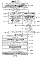
次に、こうして構成された実施例のハイブリッド自動車20の動作について説明する。図2は、ハイブリッド用電子制御ユニット70により実行される駆動制御ルーチンの一例を示すフローチャートである。このルーチンは、所定時間毎(例えば数msec毎)に繰り返し実行される。
Next, the operation of the thus configured
駆動制御ルーチンが実行されると、ハイブリッド用電子制御ユニット70のCPU72は、まず、アクセルペダルポジションセンサ84からのアクセル開度Accやブレーキペダルポジションセンサ86からのブレーキペダルポジションBP,車速センサ88からの車速V,モータMG1,MG2の回転数Nm1,Nm2,バッテリ50の残容量SOC,バッテリ50の入出力制限Win,Wout,クルーズコントロールスイッチ89からのクルーズコントロール信号CSWなど制御に必要なデータを入力する処理を実行する(ステップS100)。ここで、モータMG1,MG2の回転数Nm1,Nm2は、回転位置検出センサ43,44により検出されるモータMG1,MG2の回転子の回転位置に基づいて計算されたものをモータECU40から通信により入力するものとした。また、バッテリ50の残容量SOCは、図示しない電流センサにより検出された充放電電流の積算値に基づいて演算されたものをバッテリECU52から通信により入力するものとした。さらに、バッテリ50の入出力制限Win,Woutは、温度センサ51により検出されたバッテリ50の電池温度Tbとバッテリ50の残容量SOCとに基づいて設定されたものをバッテリECU52から通信により入力するものとした。なお、バッテリ50の入出力制限Win,Woutは、電池温度Tbに基づいて入出力制限Win,Woutの基本値を設定し、バッテリ50の残容量SOCに基づいて出力制限用補正係数と入力制限用補正係数とを設定し、設定した入出力制限Win,Woutの基本値に補正係数を乗じて入出力制限Win,Woutを設定することができる。図3に電池温度Tbと入出力制限Win,Woutの基本値との関係の一例を示し、図4にバッテリ50の残容量SOCと入出力制限Win,Woutの補正係数との関係の一例を示す。クルーズコントロール信号CSWは、前述したように、モードスイッチ89aからの信号と目標車速設定スイッチ89bからの信号とにより構成されており、モードスイッチ89aにより定速走行モードが設定されると共に目標車速設定スイッチ89bにより目標車速V*が設定されたときにクルーズコントロール制御を実行する。
When the drive control routine is executed, the
こうしてデータを入力すると、入力したクルーズコントロール信号CSWに基づいてクルーズコントロールスイッチ89がONされているか否かを判定し(ステップS110)、クルーズコントロールスイッチ89がONされていない、即ちOFFされていると判定されたときには、目標残容量SOC*に所定値S1を設定すると共に(ステップS120)、設定した目標残容量SOC*と残容量SOCとに基づいてバッテリ50に充放電すべき充放電要求電力Pb*を設定する(ステップS130)。ここで、所定値S1は、例えば、55%や60%などに設定される。また、充放電要求電力Pb*は、実施例では、残容量SOCから目標残容量SOC*を減じて得られる残容量差(SOC−SOC*)と充放電要求電力Pb*との関係を予め定めて充放電要求電力設定用マップとしてROM74に記憶しておき、残容量差(SOC−SOC*)が与えられると記憶したマップから対応する充放電要求電力Pb*を導出して設定するものとした。充放電要求電力設定用マップの一例を図5に示す。図5の例では、充放電要求電力Pb*は、残容量差(SOC−SOC*)が値0を含む所定範囲内(負の所定値Sref1以上かつ正の所定値Sref2以下)のときには値0が設定され、残容量差(SOC−SOC*)が正の所定値Sref2より大きいときには正(放電側)の値が設定され、残容量差(SOC−SOC*)が負の所定値Sref1より小さいときには負(充電側)の値が設定される。なお、所定値Sref1としては残容量差(SOC−SOC*)が−5%や−10%となる値などを用いることができ、所定値Sref2としては残容量差(SOC−SOC*)が5%や10%となる値などを用いることができる。
When the data is input in this way, it is determined whether or not the
続いて、入力したアクセル開度AccとブレーキペダルポジションBPと車速Vとに基づいて車両に要求されるトルクとして駆動輪63a,63bに連結されたリングギヤ軸32aに出力すべき要求トルクTr*とリングギヤ軸32aに要求される要求パワーPr*とを設定する(ステップS140)。要求トルクTr*は、実施例では、アクセル開度AccとブレーキペダルポジションBPと車速Vと要求トルクTr*との関係を予め定めて要求トルク設定用マップとしてROM74に記憶しておき、アクセル開度Accと車速Vとが与えられると記憶したマップから対応する要求トルクTr*を導出して設定するものとした。図6に要求トルク設定用マップの一例を示す。要求パワーPr*は、設定した要求トルクTr*にリングギヤ軸32aの回転数Nrを乗じることにより計算することができる。なお、リングギヤ軸32aの回転数Nrは、車速Vに換算係数kを乗じることによって求めたり、モータMG2の回転数Nm2を減速ギヤ35のギヤ比Grで割ることによって求めることができる。
Subsequently, the required torque Tr * to be output to the
そして、計算した要求パワーPr*からバッテリ50の充放電要求電力Pb*を減じることによりエンジン22に要求されるエンジン要求パワーPe*を計算し(ステップS150)、計算したエンジン要求パワーPe*に基づいてエンジン22の目標回転数Ne*と目標トルクTe*とを設定する(ステップS160)。この設定は、エンジン22を効率よく動作させる動作ラインと要求パワーPe*とに基づいて目標回転数Ne*と目標トルクTe*とを設定する。エンジン22の動作ラインの一例と目標回転数Ne*と目標トルクTe*とを設定する様子を図7に示す。図示するように、目標回転数Ne*と目標トルクTe*は、動作ラインと要求パワーPe*(Ne*×Te*)が一定の曲線との交点により求めることができる。
Then, the engine required power Pe * required for the
次に、設定した目標回転数Ne*とリングギヤ軸32aの回転数Nr(=Nm2/Gr)と動力分配統合機構30のギヤ比ρとを用いて次式(1)によりモータMG1の目標回転数Nm1*を計算すると共に計算した目標回転数Nm1*と現在の回転数Nm1とに基づいて式(2)によりモータMG1のトルク指令Tm1*を計算する(ステップS170)。ここで、式(1)は、動力分配統合機構30の回転要素に対する力学的な関係式である。動力分配統合機構30の回転要素における回転数とトルクとの力学的な関係を示す共線図の一例を図8に示す。図中、左のS軸はモータMG1の回転数Nm1であるサンギヤ31の回転数を示し、C軸はエンジン22の回転数Neであるキャリア34の回転数を示し、R軸はモータMG2の回転数Nm2を減速ギヤ35のギヤ比Grで除したリングギヤ32の回転数Nrを示す。式(1)は、この共線図を用いれば容易に導くことができる。なお、R軸上の2つの太線矢印は、エンジン22を目標回転数Ne*および目標トルクTe*の運転ポイントで定常運転したときにエンジン22から出力されるトルクTe*がリングギヤ軸32aに伝達されるトルクと、モータMG2から出力されるトルクTm2*が減速ギヤ35を介してリングギヤ軸32aに作用するトルクとを示す。また、式(2)は、モータMG1を目標回転数Nm1*で回転させるためのフィードバック制御における関係式であり、式(2)中、右辺第2項の「k1」は比例項のゲインであり、右辺第3項の「k2」は積分項のゲインである。
Next, using the set target rotational speed Ne *, the rotational speed Nr (= Nm2 / Gr) of the
Nm1*=Ne*・(1+ρ)/ρ-Nm2/(Gr・ρ) (1)
Tm1*=前回Tm1*+k1・(Nm1*-Nm1)+k2・∫(Nm1*-Nm1)dt (2)
Nm1 * = Ne * ・ (1 + ρ) / ρ-Nm2 / (Gr ・ ρ) (1)
Tm1 * = previous Tm1 * + k1 ・ (Nm1 * -Nm1) + k2 ・ ∫ (Nm1 * -Nm1) dt (2)
こうしてモータMG1の目標回転数Nm1*とトルク指令Tm1*とを計算すると、バッテリ50の入出力制限Win,Woutと計算したモータMG1のトルク指令Tm1*に現在のモータMG1の回転数Nm1を乗じて得られるモータMG1の消費電力(発電電力)との偏差をモータMG2の回転数Nm2で割ることによりモータMG2から出力してもよいトルクの上下限としてのトルク制限Tmin,Tmaxを次式(3)および式(4)により計算すると共に(ステップS180)、要求トルクTr*とトルク指令Tm1*と動力分配統合機構30のギヤ比ρを用いてモータMG2から出力すべきトルクとしての仮モータトルクTm2tmpを式(5)により計算し(ステップS190)、計算したトルク制限Tmin,Tmaxで仮モータトルクTm2tmpを制限した値としてモータMG2のトルク指令Tm2*を設定する(ステップS200)。このようにモータMG2のトルク指令Tm2*を設定することにより、リングギヤ軸32aに出力する要求トルクTr*を、バッテリ50の入出力制限Win,Woutの範囲内で制限したトルクとして設定することができる。なお、式(5)は、前述した図8の共線図から容易に導き出すことができる。
When the target rotational speed Nm1 * and the torque command Tm1 * of the motor MG1 are thus calculated, the input / output limits Win and Wout of the
Tmin=(Win-Tm1*・Nm1)/Nm2 (3)
Tmax=(Wout-Tm1*・Nm1)/Nm2 (4)
Tm2tmp=(Tr*+Tm1*/ρ)/Gr (5)
Tmin = (Win-Tm1 * ・ Nm1) / Nm2 (3)
Tmax = (Wout-Tm1 * ・ Nm1) / Nm2 (4)
Tm2tmp = (Tr * + Tm1 * / ρ) / Gr (5)
こうしてエンジン22の目標回転数Ne*や目標トルクTe*,モータMG1,MG2のトルク指令Tm1*,Tm2*を設定すると、エンジン22の目標回転数Ne*と目標トルクTe*についてはエンジンECU24に、モータMG1,MG2のトルク指令Tm1*,Tm2*についてはモータECU40にそれぞれ送信して(ステップS210)、駆動制御ルーチンを終了する。目標回転数Ne*と目標トルクTe*とを受信したエンジンECU24は、エンジン22が目標回転数Ne*と目標トルクTe*とによって示される運転ポイントで運転されるようにエンジン22における燃料噴射制御や点火制御などの制御を行なう。また、トルク指令Tm1*,Tm2*を受信したモータECU40は、トルク指令Tm1*でモータMG1が駆動されると共にトルク指令Tm2*でモータMG2が駆動されるようインバータ41,42のスイッチング素子のスイッチング制御を行なう。
Thus, when the target engine speed Ne *, the target torque Te *, and the torque commands Tm1 *, Tm2 * of the motors MG1, MG2 are set, the target engine speed Ne * and the target torque Te * of the
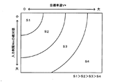
ステップS110でクルーズコントロールスイッチ89がONされていると判定されたときには、目標車速V*とバッテリ50の入力制限Winとに基づいてバッテリ50の目標残容量SOC*を設定すると共に(ステップS220)、設定した目標残容量SOC*と残容量SOCとに基づいて前述した図5の充放電要求電力設定用マップを用いて充放電要求電力Pb*を設定する(ステップS230)。バッテリ50の目標残容量SOC*は、実施例では、目標車速V*とバッテリ50の入力制限Winと目標残容量SOC*との関係を予め定めて目標残容量設定用マップとしてROM74に記憶しておき、目標車速V*と入力制限Winとが与えられると記憶したマップから対応する目標残容量SOC*を導出して設定するものとした。目標残容量設定用マップの一例を図9に示す。目標残容量SOC*は、図示するように、目標車速V*が大きいほど小さくなる傾向に設定し、バッテリ50の入力制限Winが制限されていないほど(絶対値が大きいほど)小さくなる傾向に設定するものとした。いま、クルーズコントロールスイッチ89がONされていて比較的高速で定速走行している状態のときに運転者によりブレーキペダル85が比較的大きく踏み込まれて車速Vが低下するときを考える。この場合の動力分配統合機構30の回転要素における回転数とトルクとの力学的な関係を示す共線図の一例を図10に示す。運転者によりブレーキペダル85が比較的大きく踏み込まれたときには、クルーズコントロール制御が解除され、要求トルクTr*に負の値が設定され、図10の共線図に示すように、モータMG2から制動トルクを出力することになる。このとき、モータMG2は発電機として機能し、モータMG2により発電された電力はバッテリ50に充電されることになる。車両が停止するまでにモータMG2により回生可能なエネルギは、ブレーキペダル85が踏み込まれる前の車速Vが高いほど多くなる。また、バッテリ50の入力制限Winが制限されていないほど(絶対値が大きいほど)バッテリ50に充電可能な電力は多くなり、低温時などバッテリ50の入力制限Winが大きく制限されているときにはバッテリ50に充電可能な電力は制限される。したがって、実施例では、目標車速V*が大きいほど小さくなる傾向に且つバッテリ50の入力制限Winが制限されていないほど小さくなる傾向にバッテリ50の目標残容量SOC*を設定するものとした。このように、目標車速V*およびバッテリ50の入力制限Winに応じて目標残容量SOC*を設定することにより、目標車速V*だけに基づいて目標残容量SOC*を設定するものに比して目標残容量SOC*をより適正に設定することができる。
When it is determined in step S110 that the
続いて、目標車速V*と車速Vとの差としての車速差(V*−V)が打ち消されるよう要求トルクTr*を次式(6)により計算する(ステップS240)。ここで、式(6)は、車速Vが目標車速V*となるようにするためのフィードバック制御の関係式であり、式(6)中、右辺第1項の「k3」は比例項のゲインであり、右辺第2項の「k4」は積分項のゲインである。 Subsequently, the required torque Tr * is calculated by the following equation (6) so that the vehicle speed difference (V * −V) as the difference between the target vehicle speed V * and the vehicle speed V is canceled (step S240). Here, Expression (6) is a relational expression of feedback control for causing the vehicle speed V to become the target vehicle speed V *. In Expression (6), “k3” in the first term on the right side is a gain of a proportional term. “K4” in the second term on the right side is the gain of the integral term.
Tr*=k3・(V*-V)+k4・∫(V*-V)dt (6) Tr * = k3 ・ (V * -V) + k4 ・ ∫ (V * -V) dt (6)
そして、バッテリ50の残容量SOCを目標残容量SOC*と比較する(ステップS250)。ステップS250の残容量SOCと目標残容量SOC*との比較は、バッテリ50が放電要求している可能性があるか否か、即ち充放電要求電力Pb*が正である可能性があるか否かを判定する処理である。残容量SOCが目標残容量SOC*以下のときには、こうした可能性はないと判断し、要求パワーPr*から充放電要求電力Pb*を減じることによりエンジン要求パワーPe*を計算し(ステップS150)、ステップS160〜S210の処理を実行して駆動制御ルーチンを終了する。この場合、充放電要求電力Pb*に応じてバッテリ50の充電が行なわれる。
Then, the remaining capacity SOC of the
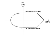
一方、ステップS250でバッテリ50の残容量SOCが目標残容量SOC*より大きいときには、バッテリ50が放電要求している可能性があると判断し、要求パワーPr*を閾値Prefと比較し(ステップS260)、要求パワーPr*が閾値Pref以上のときには、要求パワーPr*から充放電要求電力Pb*を減じることによりエンジン要求パワーPe*を計算し(ステップS150)、ステップS160〜S210の処理を実行して駆動制御ルーチンを終了し、要求パワーPr*が閾値Pref未満のときには要求パワーPr*をエンジン要求パワーPe*として設定し(ステップS270)、ステップS160〜S210の処理を実行して駆動制御ルーチンを終了する。ここで、閾値Prefは、バッテリ50の放電を伴って要求トルクTr*をリングギヤ軸32aに出力する際に、エンジン22を効率よく運転できるパワーの下限値近傍の値として設定される。エンジン22の動作ラインとエンジン22の効率との関係の一例を図11に示す。エンジン22の動作ライン上にエンジン22の目標回転数Ne*および目標トルクTe*を設定する際のエンジン22の効率は、図示するように、エンジン要求パワーPe*が所定パワーP1未満のときにはエンジン要求パワーPe*が大きくなるほど上昇し、エンジン要求パワーPe*が所定パワーP1以上のときにはエンジン要求パワーPe*が大きくなるほど低下する。したがって、バッテリ50の残容量SOCが目標残容量SOC*より大きいときに、要求パワーPr*が所定パワーP1未満のときに要求パワーPr*から充放電要求電力Pb*(値0以上)を減じたものをエンジン要求パワーPe*として設定すると、要求パワーPr*をエンジン要求パワーPe*として設定するものに比してエンジン22の効率が低下することがある。実施例では、こうしたエンジン22の効率の低下を抑制するために、バッテリ50の残容量SOCが目標残容量SOC*より大きいときに、要求パワーPr*が閾値Pref未満のときには要求パワーPr*をエンジン要求パワーPe*として設定するものとし、要求パワーPr*が閾値Pref以上のときには要求パワーPrから充放電要求電力Pb*を減じたものをエンジン要求パワーPe*に設定するものとした。ここで、閾値Prefには、所定パワーP1を用いるものとしてもよいし、所定パワーP1より若干小さいパワーや若干大きいパワーを用いるものとしてもよい。このようにエンジン要求パワーPe*を設定することにより、エンジン要求パワーPe*が比較的小さいときにバッテリ50から放電を行なうのを抑制すると共にエンジン要求パワーPe*が比較的大きいときにバッテリ50から放電を行なうから、エンジン22の効率をそれほど低下させることなく、バッテリ50の残容量SOCを目標残容量SOC*に近づけることができる。
On the other hand, when the remaining capacity SOC of the
以上説明した実施例のハイブリッド自動車20によれば、クルーズコントロールスイッチ89がONされているときには、目標車速V*とバッテリ50の入力制限Winとに基づいてバッテリ50の目標残容量SOC*を設定すると共に目標残容量SOC*と残容量SOCとに基づいてバッテリ50に充放電すべき充放電要求電力Pb*を設定し、設定した充放電要求電力Pb*によりバッテリ50が充放電されると共に要求トルクTr*に基づく駆動力により走行するようエンジン22とモータMG1,MG2とを制御するから、目標車速V*だけに基づいて目標残容量SOC*を設定するものに比して目標残容量SOC*をより適正に設定することができ、車両が減速する際の回生性能をより向上させることができる。この結果、車両のエネルギ効率の向上を図ることができる。しかも、実施例のハイブリッド自動車20によれば、クルーズコントロールスイッチ89がONされているときにバッテリ50の残容量SOCが目標残容量SOC*より大きいときには、要求パワーPr*が比較的大きいときにバッテリ50から放電を行なうと共に要求パワーPr*がそれほど大きくないときにはバッテリ50から放電を行なわないから、バッテリ50の残容量SOCを目標残容量SOC*に近づける際にエンジン22の効率が低下するのを抑制することができる。
According to the
実施例のハイブリッド自動車20では、クルーズコントロールスイッチ89がONされているときであってバッテリ50の残容量SOCが目標残容量SOC*より大きいときには、要求パワーPr*が閾値Pref以上のときにバッテリ50から放電を行なって残容量SOCを目標残容量SOC*に近づけるものとしたが、要求パワーPr*に拘わらずバッテリ50の放電を行なって残容量SOCを目標残容量SOC*に近づけるものとしてもよい。
In the
実施例のハイブリッド自動車20では、クルーズコントロールスイッチ89がONされているときであってバッテリ50の残容量SOCが目標残容量SOC*以下のときには、要求パワーPr*に拘わらず、要求パワーPr*から充放電要求電力Pb*(値0以下)を減じることによりエンジン要求パワーPe*を設定するものとしたが、要求パワーPr*を閾値Pref2と比較し、要求パワーPr*が閾値Pref2以上のときには要求パワーPr*をエンジン要求パワーPe*として設定し、要求パワーPr*が閾値Pref2未満のときには要求パワーPr*から充放電要求電力Pb*を減じることによりエンジン要求パワーPe*を設定するものとしてもよい。ここで、閾値Pref2は、バッテリ50の充電を伴って要求トルクTr*をリングギヤ軸32aに出力する際に、エンジン22を効率よく運転できるパワーの上限値近傍の値として設定される。以下、この理由について説明する。バッテリ50の残容量SOCが目標残容量SOC*以下のときには、充放電要求電力Pb*に負の値である可能性、即ちバッテリ50は充電要求している可能性がある。また、図11のエンジン22の動作ラインとエンジン22の効率との関係の一例に示したように、エンジン22の動作ライン上にエンジン22の目標回転数Ne*および目標トルクTe*を設定する際のエンジン22の効率は、エンジン要求パワーPe*が所定パワーP1未満のときにはエンジン要求パワーPe*が大きくなるほど上昇し、エンジン要求パワーPe*が所定パワーP1以上のときにはエンジン要求パワーPe*が大きくなるほど低下する。したがって、要求パワーPr*が所定パワーP1以上のときに要求パワーPr*から充放電要求電力Pb*(値0以下)を減じたものをエンジン要求パワーPe*として設定すると、要求パワーPr*をエンジン要求パワーPe*として設定するものに比してエンジン22の効率が低下することになる。変形例では、こうしたエンジン22の効率の低下を抑制するために、要求パワーPr*が閾値Pref2未満のときには要求パワーPr*から充放電要求電力Pb*を減じたものをエンジン要求パワーPe*として設定するものとし、要求パワーPr*が閾値Pref2以上のときには要求パワーPr*をエンジン要求パワーPe*として設定するものとした。ここで、閾値Pref2には、所定パワーP1を用いるものとしてもよいし、所定パワーP1より若干小さいパワーや若干大きいパワーを用いるものとしてもよい。このようにエンジン要求パワーPe*を設定することにより、要求パワーPr*が比較的大きいときにバッテリ50の充電を行なうのを抑制すると共に要求パワーPr*が比較的小さいときにバッテリ50の充電を行なうから、バッテリ50の残容量SOCを目標残容量SOC*に近づける際にエンジン22の効率が低下するのを抑制することができる。
In the
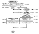
実施例のハイブリッド自動車20では、クルーズコントロールスイッチ89がOFFされているときには所定値S1をバッテリ50の目標残容量SOC*として設定し、クルーズコントロールスイッチ89がONされているときには目標車速V*とバッテリ50の入力制限Winとに基づいて目標残容量SOC*を設定するものとしたが、クルーズコントロールスイッチ89がOFFされているときやクルーズコントロールスイッチ89を備えない車両であっても、車両がある程度の車速Vで定速走行しているときなどには、定速走行時の平均車速Vaveとバッテリ50の入力制限Winとに基づいてバッテリ50の目標残容量SOC*を設定するものとしてもよい。図12は、クルーズコントロールスイッチ89を備えない車両における駆動制御ルーチンの一例の一部である。この駆動制御ルーチンのうち図2の駆動制御ルーチンと同一の処理については同一のステップ番号を付し、その詳細な説明は省略する。この駆動制御ルーチンでは、アクセル開度AccやブレーキペダルポジションBP,車速V,モータMG1,MG2の回転数Nm1,Nm2,バッテリ50の残容量SOC,バッテリ50の入出力制限Win,Woutなど制御に必要なデータを入力し(ステップS100b)、車速Vを閾値Vref1と比較すると共に(ステップS300)、車速Vが閾値Vref1以上のときには、今回の車速Vから前回の車速(前回v)を減じた車速変化量ΔVの絶対値を閾値Vref2と比較し(ステップS310)、車速変化量ΔVの絶対値が閾値Vref2以下のときには、車速Vが閾値Vref1以上且つ車速変化量ΔVの絶対値が閾値Vref2以下の状態が所定時間に亘って継続しているか否かを判定する(ステップS320)。ここで、閾値Vref1は、現在の車速Vから車両が停止するまでに回生可能なエネルギに応じて目標残容量SOC*を設定する必要があるか否かを判定するために用いられる閾値であり、例えば、40km/hなどに設定される。また、閾値Vref2は、車速Vがそれほど大きく変化していないか否かを判定するために用いられる閾値であり、例えば、3km/hや5km/hなどに設定される。さらに、所定時間は、車両が定速走行しているか否かを判定するために用いられる閾値であり、例えば、1secや2secなどに設定される。したがって、ステップS300〜S320の処理は、車両がある程度の車速Vで定速走行しているか否かを判定する処理となる。車速Vが閾値Vref1未満のときや、車速Vが閾値Vref1以上であっても車速変化量ΔVの絶対値が閾値Vref2より大きいとき,車速Vが閾値Vref1以上であると共に車速変化量ΔVの絶対値が閾値Vref2以下であってもその状態が未だ所定時間に亘って継続していないときには、車両がある程度の車速Vで定速走行していないと判断し、所定値S1を目標残容量SOC*として設定し(ステップS120)、ステップS130以降の処理を実行する。一方、車速Vが閾値Vref1以上であると共に車速変化量ΔVの絶対値が閾値Vref2以下でありその状態が所定時間に亘って継続しているときには、車両がある程度の車速Vで定速走行していると判断し、今回の車速Vを含む過去n回(例えば、3回や5回,10回など)の車速Vの平均値としての平均車速Vaveを計算し(ステップS330)、計算した平均車速Vaveとバッテリ50の入力制限Winとに基づいてバッテリ50の目標残容量SOC*を設定し(ステップS340)、ステップS230以降の処理を実行する。ここで、車両がある程度の車速Vで定速走行しているときの目標残容量SOC*は、変形例では、平均車速Vaveとバッテリ50の入力制限Winと目標残容量SOC*との関係を予め定めて目標残容量設定用マップとしてROM74に記憶しておき、目標車速V*と入力制限Winとが与えられると記憶したマップから対応する目標残容量SOC*を導出して設定するものとした。この変形例の目標残容量設定用マップの一例を図13に示す。目標残容量SOC*は、図示するように、平均車速Vaveが閾値Vref1以上の領域で大きいほど小さくなる傾向に設定し、バッテリ50の入力制限Winが制限されていないほど(絶対値が大きいほど)小さくなる傾向に設定するものとした。この理由については前述した。このように、平均車速Vaveおよびバッテリ50の入力制限Winに応じて目標残容量SOC*を設定することにより、平均車速Vaveだけに基づいて目標残容量SOC*を設定するものに比して目標残容量SOC*をより適正に設定することができる。この結果、車両のエネルギ効率の向上を図ることができる。なお、車両がある程度の車速Vで定速走行しているときにバッテリ50の残容量SOCが目標残容量SOC*より大きいときには、運転者によりアクセルペダル83が踏み増されたときなどのようにリングギヤ軸32aに比較的大きなパワーが要求されたときにだけバッテリ50から放電を行なって目標残容量SOC*にバッテリ50の現在の残容量SOCを近づけるものとしてもよいし、リングギヤ軸32aに要求されるパワーに拘わらずバッテリ50から放電を行なって目標残容量SOC*にバッテリ50の現在の残容量SOCを近づけるものとしてもよい。前者の場合には、実施例と同様に、バッテリ50の残容量SOCを目標残容量SOC*に近づける際にエンジン22の効率が低下するのを抑制することができる。
In the
実施例のハイブリッド自動車20では、モータMG2の動力を減速ギヤ35により変速してリングギヤ軸32aに出力するものとしたが、図14の変形例のハイブリッド自動車120に例示するように、モータMG2の動力をリングギヤ軸32aが接続された車軸(駆動輪63a,63bが接続された車軸)とは異なる車軸(図14における車輪63c,63dに接続された車軸)に出力するものとしてもよい。
In the
実施例のハイブリッド自動車20では、エンジン22の動力を動力分配統合機構30を介して駆動輪63a,63bに接続されたリングギヤ軸32aに出力するものとしたが、図15の変形例のハイブリッド自動車220に例示するように、エンジン22のクランクシャフト26に接続されたインナーロータ232と駆動輪63a,63bに動力を出力する駆動軸に接続されたアウターロータ234とを有し、エンジン22の動力の一部を駆動軸に伝達すると共に残余の動力を電力に変換する対ロータ電動機230を備えるものとしてもよい。
In the
実施例では、エンジン22と動力分配統合機構30とモータMG1とを発電手段として備えると共にモータMG2を備えるハイブリッド自動車20について説明したが、例えば、燃料電池を発電手段として備え、モータからの動力により走行する車両などに適用するものとしてもよい。この場合、バッテリが要求する要求充放電電力によりバッテリが充放電されると共に走行に要求される要求トルクにより走行するよう燃料電池とモータとを制御することになる。
In the embodiment, the
実施例では、エンジン22と動力分配統合機構30とモータMG1とを動力出力手段として備えると共にモータMG2を備えるハイブリッド自動車20について説明したが、例えば、エンジンだけを動力出力手段として備え、エンジンからの動力とモータからの動力とを用いて走行可能な車両などに適用するものとしてもよい。この場合、バッテリが要求する要求充放電電力によりバッテリが充放電されると共に走行に要求される要求トルクにより走行するようエンジンとモータとを制御することになる。
In the embodiment, the
以上、本発明を実施するための最良の形態について実施例を用いて説明したが、本発明はこうした実施例に何等限定されるものではなく、本発明の要旨を逸脱しない範囲内において、種々なる形態で実施し得ることは勿論である。 The best mode for carrying out the present invention has been described with reference to the embodiments. However, the present invention is not limited to these embodiments, and various modifications can be made without departing from the gist of the present invention. Of course, it can be implemented in the form.
20,120,220 ハイブリッド自動車、22 エンジン、24 エンジン用電子制御ユニット(エンジンECU)、26 クランクシャフト、28 ダンパ、30 動力分配統合機構、31 サンギヤ、32 リングギヤ、32a リングギヤ軸、33 ピニオンギヤ、34 キャリア、35,減速ギヤ、40 モータ用電子制御ユニット(モータECU)、41,42 インバータ、43,44 回転位置検出センサ、50 バッテリ、51 温度センサ、52 バッテリ用電子制御ユニット(バッテリECU)、54 電力ライン、60 ギヤ機構、62 デファレンシャルギヤ、63a,63b,63c,63d 駆動輪、70 ハイブリッド用電子制御ユニット、72 CPU、74 ROM、76 RAM、80 イグニッションスイッチ、81 シフトレバー、82 シフトポジションセンサ、83 アクセルペダル、84 アクセルペダルポジションセンサ、85 ブレーキペダル、86 ブレーキペダルポジションセンサ、88 車速センサ、89 クルーズコントロールスイッチ、89a モードスイッチ、89b 目標車速設定スイッチ、230 対ロータ電動機、232 インナーロータ 234 アウターロータ、MG1,MG2 モータ。
20, 120, 220 Hybrid vehicle, 22 engine, 24 engine electronic control unit (engine ECU), 26 crankshaft, 28 damper, 30 power distribution integration mechanism, 31 sun gear, 32 ring gear, 32a ring gear shaft, 33 pinion gear, 34 carrier , 35, reduction gear, 40 motor electronic control unit (motor ECU), 41, 42 inverter, 43, 44 rotational position detection sensor, 50 battery, 51 temperature sensor, 52 battery electronic control unit (battery ECU), 54 electric power Line, 60 gear mechanism, 62 differential gear, 63a, 63b, 63c, 63d drive wheel, 70 hybrid electronic control unit, 72 CPU, 74 ROM, 76 RAM, 80 ignition switch, 81 shift lever, 2 shift position sensor, 83 accelerator pedal, 84 accelerator pedal position sensor, 85 brake pedal, 86 brake pedal position sensor, 88 vehicle speed sensor, 89 cruise control switch, 89a mode switch, 89b target vehicle speed setting switch, 230 to rotor motor, 232
Claims (9)
前記車軸側に動力を入出力可能な電動機と、
前記電動機と電力をやりとり可能な蓄電手段と、
前記蓄電手段の蓄電状態を検出する蓄電状態検出手段と、
車速を検出する車速検出手段と、
運転者の操作により目標車速を設定する目標車速設定手段と、
前記目標車速設定手段により前記目標車速が設定されている所定の走行条件が成立しているときには前記目標車速と前記蓄電手段の入力制限とに基づいて該蓄電手段の目標蓄電状態を設定すると共に該設定した蓄電手段の目標蓄電状態と前記検出された蓄電手段の蓄電状態とに基づいて前記蓄電手段に充放電すべき目標充放電電力を設定し、前記所定の走行条件が成立しているときであって前記検出された蓄電手段の蓄電状態が前記設定した蓄電手段の目標蓄電状態よりも大きいときにおいて、前記検出された車速が前記設定された目標車速に近づくよう設定される要求駆動力に基づく要求動力が所定動力以上のときには該要求動力と前記設定した目標充放電電力とに基づく動力が前記動力出力手段から出力されながら前記要求駆動力に基づく駆動力により走行するよう前記動力出力手段と前記電動機とを制御し、前記要求動力が前記所定動力未満のときには該要求動力が前記動力出力手段から出力されながら前記要求駆動力に基づく駆動力により走行するよう前記動力出力手段と前記電動機とを制御する制御手段と、
を備える車両。 Power output means capable of outputting power to the axle side;
An electric motor capable of inputting and outputting power to the axle side;
Power storage means capable of exchanging electric power with the electric motor;
A storage state detection unit for detecting a storage state of the storage unit;
Vehicle speed detection means for detecting the vehicle speed;
Target vehicle speed setting means for setting the target vehicle speed by the operation of the driver;
When a predetermined traveling condition in which the target vehicle speed is set by the target vehicle speed setting means is satisfied, a target power storage state of the power storage means is set based on the target vehicle speed and an input restriction of the power storage means, and Based on the set target power storage state of the power storage means and the detected power storage state of the power storage means, the target charge / discharge power to be charged / discharged to the power storage means is set, and the predetermined traveling condition is satisfied. When the detected power storage state of the power storage means is larger than the target power storage state of the set power storage means, the detected vehicle speed is based on the required driving force set to approach the set target vehicle speed. When the required power is equal to or greater than the predetermined power, the power based on the required power and the set target charge / discharge power is output from the power output means while the power is based on the required drive power. The power output means and the electric motor are controlled so as to travel by driving force, and when the required power is less than the predetermined power, the required power is output from the power output means while traveling by the driving force based on the required driving force. Control means for controlling the power output means and the electric motor to
A vehicle comprising:
前記車軸側に動力を入出力可能な電動機と、
前記電動機と電力をやりとり可能な蓄電手段と、
前記蓄電手段の蓄電状態を検出する蓄電状態検出手段と、
車速を検出する車速検出手段と、
前記検出された車速が所定車速以上である条件と該車速の変化量が所定範囲内である条件とが共に所定時間に亘って成立している所定の走行条件が成立しているときには、前記検出された車速の平均値としての平均車速と前記蓄電手段の入力制限とに基づいて該蓄電手段の目標蓄電状態を設定すると共に該設定した蓄電手段の目標蓄電状態と前記検出された蓄電手段の蓄電状態とに基づいて前記蓄電手段に充放電すべき目標充放電電力を設定し、前記所定の走行条件が成立しているときであって前記検出された蓄電手段の蓄電状態が前記設定した蓄電手段の目標蓄電状態よりも大きいときにおいて、走行に要求される要求駆動力に基づく要求動力が所定動力以上のときには該要求動力と前記設定した目標充放電電力とに基づく動力が前記動力出力手段から出力されながら前記要求駆動力に基づく駆動力により走行するよう前記動力出力手段と前記電動機とを制御し、前記要求動力が前記所定動力未満のときには該要求動力が前記動力出力手段から出力されながら前記要求駆動力に基づく駆動力により走行するよう前記動力出力手段と前記電動機とを制御する制御手段と、
を備える車両。 Power output means capable of outputting power to the axle side;
An electric motor capable of inputting and outputting power to the axle side;
Power storage means capable of exchanging electric power with the electric motor;
A storage state detection unit for detecting a storage state of the storage unit;
Vehicle speed detection means for detecting the vehicle speed;
When a predetermined traveling condition is satisfied in which both the condition that the detected vehicle speed is equal to or higher than the predetermined vehicle speed and the condition that the amount of change in the vehicle speed is within a predetermined range are satisfied over a predetermined time, the detection is performed. The target power storage state of the power storage means is set based on the average vehicle speed as an average value of the set vehicle speed and the input restriction of the power storage means, and the set target power storage state of the power storage means and the detected power storage of the power storage means The target charging / discharging power to be charged / discharged to the power storage means is set based on the state, and the detected power storage state of the power storage means is when the predetermined traveling condition is satisfied. When the required power based on the required driving force required for traveling is greater than or equal to a predetermined power when the power storage state is greater than the target power storage state, the power based on the required power and the set target charge / discharge power is the power. The power output means and the electric motor are controlled so as to travel with a driving force based on the required driving force while being output from the force means. When the required power is less than the predetermined power, the required power is output from the power output means. Control means for controlling the power output means and the electric motor so as to travel with a driving force based on the required driving force,
A vehicle comprising:
前記動力出力手段は、内燃機関と、該内燃機関の出力軸と前記車軸側とに接続され電力と動力の入出力を伴って該内燃機関からの動力の少なくとも一部を該車軸側に出力可能な電力動力入出力手段と、を備え、
前記蓄電手段は、前記電力動力入出力手段および前記電動機と電力をやりとり可能な手段である
車両。 The vehicle according to claim 1 or 2 ,
The power output means is connected to the internal combustion engine, the output shaft of the internal combustion engine and the axle side, and can output at least part of the power from the internal combustion engine to the axle side with input and output of electric power and power. Power input / output means,
The power storage means is means capable of exchanging electric power with the electric power drive input / output means and the electric motor vehicle.
前記車軸側に動力を入出力可能な電動機と、
前記発電機および前記電動機と電力をやりとり可能な蓄電手段と、
前記蓄電手段の蓄電状態を検出する蓄電状態検出手段と、
車速を検出する車速検出手段と、
運転者の操作により目標車速を設定する目標車速設定手段と、
前記目標車速設定手段により前記目標車速が設定されている所定の走行条件が成立しているときには前記目標車速と前記蓄電手段の入力制限とに基づいて該蓄電手段の目標蓄電状態を設定すると共に該設定した蓄電手段の目標蓄電状態と前記検出された蓄電手段の蓄電状態とに基づいて前記蓄電手段に充放電すべき目標充放電電力を設定し、前記所定の走行条件が成立しているときであって前記検出された蓄電手段の蓄電状態が前記設定した蓄電手段の目標蓄電状態よりも大きいときにおいて、前記検出された車速が前記設定された目標車速に近づくよう設定される要求駆動力に基づく要求動力が所定動力以上のときには該要求動力と前記設定した目標充放電電力とに基づく動力が前記内燃機関から出力されながら前記要求駆動力に基づく駆動力により走行するよう前記内燃機関と前記発電機と前記電動機とを制御し、前記要求動力が前記所定動力未満のときには該要求動力が前記内燃機関から出力されながら前記要求駆動力に基づく駆動力により走行するよう前記内燃機関と前記発電機と前記電動機とを制御する制御手段と、
を備える車両。 An internal combustion engine, and a generator that generates electric power using power from the internal combustion engine;
An electric motor capable of inputting and outputting power to the axle side;
Power storage means capable of exchanging electric power with the generator and the motor;
A storage state detection unit for detecting a storage state of the storage unit;
Vehicle speed detection means for detecting the vehicle speed;
Target vehicle speed setting means for setting the target vehicle speed by the operation of the driver;
When a predetermined traveling condition in which the target vehicle speed is set by the target vehicle speed setting means is satisfied, a target power storage state of the power storage means is set based on the target vehicle speed and an input restriction of the power storage means, and Based on the set target power storage state of the power storage means and the detected power storage state of the power storage means, the target charge / discharge power to be charged / discharged to the power storage means is set, and the predetermined traveling condition is satisfied. When the detected power storage state of the power storage means is larger than the target power storage state of the set power storage means, the detected vehicle speed is based on the required driving force set to approach the set target vehicle speed. When the required power is equal to or higher than the predetermined power, the power based on the required power and the set target charge / discharge power is output from the internal combustion engine while driving based on the required drive power. The internal combustion engine, the generator, and the motor are controlled so as to travel by force, and when the required power is less than the predetermined power, the required power is output from the internal combustion engine while being driven by the driving force based on the required driving force. Control means for controlling the internal combustion engine, the generator and the electric motor so as to travel;
A vehicle comprising:
運転者の操作により目標車速が設定されている所定の走行条件が成立しているときには前記目標車速と前記蓄電手段の入力制限とに基づいて該蓄電手段の目標蓄電状態を設定すると共に該設定した蓄電手段の目標蓄電状態と該蓄電手段の蓄電状態とに基づいて前記蓄電手段に充放電すべき目標充放電電力を設定し、前記所定の走行条件が成立しているときであって前記蓄電手段の蓄電状態が前記設定した蓄電手段の目標蓄電状態よりも大きいときにおいて、車速が前記目標車速に近づくよう設定される要求駆動力に基づく要求動力が所定動力以上のときには該要求動力と前記設定した目標充放電電力とに基づく動力が前記動力出力手段から出力されながら前記要求駆動力に基づく駆動力により走行するよう前記動力出力手段と前記電動機とを制御し、前記要求動力が前記所定動力未満のときには該要求動力が前記動力出力手段から出力されながら前記要求駆動力に基づく駆動力により走行するよう前記動力出力手段と前記電動機とを制御する
ことを特徴とする車両の制御方法。 A vehicle control method comprising: a power output means capable of outputting power to an axle side; an electric motor capable of inputting / outputting power to the axle side; and an electric storage means capable of exchanging electric power with the electric motor,
When a predetermined traveling condition in which a target vehicle speed is set by a driver's operation is satisfied, a target power storage state of the power storage unit is set and set based on the target vehicle speed and an input limit of the power storage unit Based on the target power storage state of the power storage means and the power storage state of the power storage means, the target charge / discharge power to be charged / discharged to the power storage means is set, and the power storage means is satisfied when the predetermined traveling condition is satisfied. When the required power based on the required driving force set so that the vehicle speed approaches the target vehicle speed is greater than or equal to the predetermined power when the power storage state is greater than the target power storage state of the set power storage means. The power output means and the electric motor are driven so as to travel with the driving force based on the required driving force while the power based on the target charge / discharge power is output from the power output means. Gyoshi, said power demand is at less than the predetermined power controls said electric motor and said power output means to travel by the driving force based on the required driving force while being output the power demand from the power output unit A vehicle control method characterized by the above.
車速が所定車速以上である条件と該車速の変化量が所定範囲内である条件とが共に所定時間に亘って成立している所定の走行条件が成立しているときには、前記車速の平均値としての平均車速と前記蓄電手段の入力制限とに基づいて該蓄電手段の目標蓄電状態を設定すると共に該設定した蓄電手段の目標蓄電状態と該蓄電手段の蓄電状態とに基づいて前記蓄電手段に充放電すべき目標充放電電力を設定し、前記所定の走行条件が成立しているときであって前記蓄電手段の蓄電状態が前記設定した蓄電手段の目標蓄電状態よりも大きいときにおいて、走行に要求される要求駆動力に基づく要求動力が所定動力以上のときには該要求動力と前記設定した目標充放電電力とに基づく動力が前記動力出力手段から出力されながら前記要求駆動力に基づく駆動力により走行するよう前記動力出力手段と前記電動機とを制御し、前記要求動力が前記所定動力未満のときには該要求動力が前記動力出力手段から出力されながら前記要求駆動力に基づく駆動力により走行するよう前記動力出力手段と前記電動機とを制御する
ことを特徴とする車両の制御方法。 A vehicle control method comprising: a power output means capable of outputting power to an axle side; an electric motor capable of inputting / outputting power to the axle side; and an electric storage means capable of exchanging electric power with the electric motor,
When a predetermined traveling condition is established in which both the condition that the vehicle speed is equal to or higher than the predetermined vehicle speed and the condition that the amount of change in the vehicle speed is within a predetermined range are satisfied over a predetermined time, the average value of the vehicle speed is The target storage state of the power storage unit is set based on the average vehicle speed of the vehicle and the input restriction of the power storage unit, and the power storage unit is charged based on the set target storage state of the power storage unit and the storage state of the power storage unit. A target charge / discharge power to be discharged is set, and when the predetermined driving condition is satisfied and the power storage state of the power storage means is larger than the set target power storage state of the power storage means, a request is made for travel When the requested power based on the requested driving force is greater than or equal to the predetermined power, the power based on the requested power and the set target charge / discharge power is output from the power output means based on the requested driving force. The power output means and the electric motor are controlled so as to travel by driving force, and when the required power is less than the predetermined power, the required power is output from the power output means while traveling by the driving force based on the required driving force. A control method for a vehicle, wherein the power output means and the electric motor are controlled.
運転者の操作により目標車速が設定されている所定の走行条件が成立しているときには前記目標車速と前記蓄電手段の入力制限とに基づいて該蓄電手段の目標蓄電状態を設定すると共に該設定した蓄電手段の目標蓄電状態と該蓄電手段の蓄電状態とに基づいて前記蓄電手段に充放電すべき目標充放電電力を設定し、前記所定の走行条件が成立しているときであって前記蓄電手段の蓄電状態が前記設定した蓄電手段の目標蓄電状態よりも大きいときにおいて、車速が前記目標車速に近づくよう設定される要求駆動力に基づく要求動力が所定動力以上のときには該要求動力と前記設定した目標充放電電力とに基づく動力が前記内燃機関から出力されながら前記要求駆動力に基づく駆動力により走行するよう前記内燃機関と前記発電機と前記電動機とを制御し、前記要求動力が前記所定動力未満のときには該要求動力が前記内燃機関から出力されながら前記要求駆動力に基づく駆動力により走行するよう前記内燃機関と前記発電機と前記電動機とを制御する
ことを特徴とする車両の制御方法。
Comprising an internal combustion engine, a generator for generating electric power using the power from the internal combustion engine, a power capable output electric motor to the axle side, and a power storage unit capable exchanging power with the generator and the motor A vehicle control method comprising:
When a predetermined traveling condition in which a target vehicle speed is set by a driver's operation is satisfied, a target power storage state of the power storage unit is set and set based on the target vehicle speed and an input limit of the power storage unit Based on the target power storage state of the power storage means and the power storage state of the power storage means, the target charge / discharge power to be charged / discharged to the power storage means is set, and the power storage means is satisfied when the predetermined traveling condition is satisfied. When the required power based on the required driving force that is set so that the vehicle speed approaches the target vehicle speed when the power storage state is greater than the target power storage state of the set power storage means, The internal combustion engine, the generator, and the electric motor are driven so as to travel with a driving force based on the required driving force while power based on the target charge / discharge power is output from the internal combustion engine. When the required power is less than the predetermined power, the internal combustion engine, the generator, and the electric motor are controlled so that the required power is output from the internal combustion engine and travels with a driving force based on the required driving force. A method for controlling a vehicle.
Priority Applications (1)
| Application Number | Priority Date | Filing Date | Title |
|---|---|---|---|
| JP2006095085A JP4345765B2 (en) | 2006-03-30 | 2006-03-30 | Vehicle and control method thereof |
Applications Claiming Priority (1)
| Application Number | Priority Date | Filing Date | Title |
|---|---|---|---|
| JP2006095085A JP4345765B2 (en) | 2006-03-30 | 2006-03-30 | Vehicle and control method thereof |
Publications (2)
| Publication Number | Publication Date |
|---|---|
| JP2007269093A JP2007269093A (en) | 2007-10-18 |
| JP4345765B2 true JP4345765B2 (en) | 2009-10-14 |
Family
ID=38672336
Family Applications (1)
| Application Number | Title | Priority Date | Filing Date |
|---|---|---|---|
| JP2006095085A Expired - Fee Related JP4345765B2 (en) | 2006-03-30 | 2006-03-30 | Vehicle and control method thereof |
Country Status (1)
| Country | Link |
|---|---|
| JP (1) | JP4345765B2 (en) |
Families Citing this family (4)
| Publication number | Priority date | Publication date | Assignee | Title |
|---|---|---|---|---|
| US8504232B2 (en) | 2011-02-15 | 2013-08-06 | Toyota Jidosha Kabushiki Kaisha | Electrically powered vehicle and method for controlling the same |
| CN103596795B (en) * | 2011-06-06 | 2016-02-17 | 丰田自动车株式会社 | The driving control device of vehicle |
| KR101371463B1 (en) * | 2012-09-06 | 2014-03-24 | 기아자동차주식회사 | Method and system for controlling recharging of a battery for hybrid vehicle |
| JP6149772B2 (en) * | 2014-03-24 | 2017-06-21 | トヨタ自動車株式会社 | Hybrid vehicle |
-
2006
- 2006-03-30 JP JP2006095085A patent/JP4345765B2/en not_active Expired - Fee Related
Also Published As
| Publication number | Publication date |
|---|---|
| JP2007269093A (en) | 2007-10-18 |
Similar Documents
| Publication | Publication Date | Title |
|---|---|---|
| JP4086018B2 (en) | HYBRID VEHICLE, ITS CONTROL METHOD, AND POWER OUTPUT DEVICE | |
| JP4345824B2 (en) | Vehicle and control method thereof | |
| JP4407741B2 (en) | Vehicle and control method thereof | |
| JP4135681B2 (en) | POWER OUTPUT DEVICE, HYBRID VEHICLE HAVING THE SAME AND CONTROL METHOD THEREOF | |
| JP4229105B2 (en) | Hybrid vehicle and control method thereof | |
| JP2009227073A (en) | Hybrid vehicle, and control method for the same | |
| JP2008161023A (en) | Vehicle and control method thereof | |
| JP5200924B2 (en) | Hybrid vehicle and control method thereof | |
| JP2009126257A (en) | Vehicle and its control method | |
| JP2006262585A (en) | Hybrid vehicle and control method therefor | |
| JP4297108B2 (en) | Vehicle and control method thereof | |
| JP2006094626A (en) | Hybrid vehicle and its control method | |
| JP2006118359A (en) | Vehicle and its control method | |
| JP2009126253A (en) | Hybrid vehicle and its control method | |
| JP4345765B2 (en) | Vehicle and control method thereof | |
| JP4365354B2 (en) | Power output apparatus, automobile equipped with the same, and control method of power output apparatus | |
| JP2010064522A (en) | Vehicle and method of controlling the same | |
| JP2010195255A (en) | Hybrid vehicle and control method thereof | |
| JP4248553B2 (en) | Vehicle and control method thereof | |
| JP2005210841A (en) | Vehicle and method for controlling the same | |
| JP5691997B2 (en) | Hybrid car | |
| JP4301252B2 (en) | POWER OUTPUT DEVICE, ITS CONTROL METHOD, AND VEHICLE | |
| JP4258519B2 (en) | Vehicle and control method thereof | |
| JP2009184387A (en) | Hybrid vehicle and method of controlling the same | |
| JP2008162346A (en) | Power output unit, control method therefor, and vehicle |
Legal Events
| Date | Code | Title | Description |
|---|---|---|---|
| A621 | Written request for application examination |
Free format text: JAPANESE INTERMEDIATE CODE: A621 Effective date: 20080609 |
|
| A131 | Notification of reasons for refusal |
Free format text: JAPANESE INTERMEDIATE CODE: A131 Effective date: 20090224 |
|
| A521 | Request for written amendment filed |
Free format text: JAPANESE INTERMEDIATE CODE: A523 Effective date: 20090420 |
|
| TRDD | Decision of grant or rejection written | ||
| A01 | Written decision to grant a patent or to grant a registration (utility model) |
Free format text: JAPANESE INTERMEDIATE CODE: A01 Effective date: 20090623 |
|
| A01 | Written decision to grant a patent or to grant a registration (utility model) |
Free format text: JAPANESE INTERMEDIATE CODE: A01 |
|
| A61 | First payment of annual fees (during grant procedure) |
Free format text: JAPANESE INTERMEDIATE CODE: A61 Effective date: 20090706 |
|
| R151 | Written notification of patent or utility model registration |
Ref document number: 4345765 Country of ref document: JP Free format text: JAPANESE INTERMEDIATE CODE: R151 |
|
| FPAY | Renewal fee payment (event date is renewal date of database) |
Free format text: PAYMENT UNTIL: 20120724 Year of fee payment: 3 |
|
| FPAY | Renewal fee payment (event date is renewal date of database) |
Free format text: PAYMENT UNTIL: 20130724 Year of fee payment: 4 |
|
| LAPS | Cancellation because of no payment of annual fees |