JP4340745B2 - Laser machining method for workpieces that expand the laser spot - Google Patents
Laser machining method for workpieces that expand the laser spot Download PDFInfo
- Publication number
- JP4340745B2 JP4340745B2 JP2003559716A JP2003559716A JP4340745B2 JP 4340745 B2 JP4340745 B2 JP 4340745B2 JP 2003559716 A JP2003559716 A JP 2003559716A JP 2003559716 A JP2003559716 A JP 2003559716A JP 4340745 B2 JP4340745 B2 JP 4340745B2
- Authority
- JP
- Japan
- Prior art keywords
- laser
- primary
- workpiece
- positioning system
- relative movement
- Prior art date
- Legal status (The legal status is an assumption and is not a legal conclusion. Google has not performed a legal analysis and makes no representation as to the accuracy of the status listed.)
- Expired - Lifetime
Links
Images


Classifications
-
- B—PERFORMING OPERATIONS; TRANSPORTING
- B23—MACHINE TOOLS; METAL-WORKING NOT OTHERWISE PROVIDED FOR
- B23K—SOLDERING OR UNSOLDERING; WELDING; CLADDING OR PLATING BY SOLDERING OR WELDING; CUTTING BY APPLYING HEAT LOCALLY, e.g. FLAME CUTTING; WORKING BY LASER BEAM
- B23K26/00—Working by laser beam, e.g. welding, cutting or boring
- B23K26/08—Devices involving relative movement between laser beam and workpiece
-
- B—PERFORMING OPERATIONS; TRANSPORTING
- B23—MACHINE TOOLS; METAL-WORKING NOT OTHERWISE PROVIDED FOR
- B23K—SOLDERING OR UNSOLDERING; WELDING; CLADDING OR PLATING BY SOLDERING OR WELDING; CUTTING BY APPLYING HEAT LOCALLY, e.g. FLAME CUTTING; WORKING BY LASER BEAM
- B23K26/00—Working by laser beam, e.g. welding, cutting or boring
- B23K26/02—Positioning or observing the workpiece, e.g. with respect to the point of impact; Aligning, aiming or focusing the laser beam
- B23K26/06—Shaping the laser beam, e.g. by masks or multi-focusing
- B23K26/064—Shaping the laser beam, e.g. by masks or multi-focusing by means of optical elements, e.g. lenses, mirrors or prisms
-
- B—PERFORMING OPERATIONS; TRANSPORTING
- B23—MACHINE TOOLS; METAL-WORKING NOT OTHERWISE PROVIDED FOR
- B23K—SOLDERING OR UNSOLDERING; WELDING; CLADDING OR PLATING BY SOLDERING OR WELDING; CUTTING BY APPLYING HEAT LOCALLY, e.g. FLAME CUTTING; WORKING BY LASER BEAM
- B23K26/00—Working by laser beam, e.g. welding, cutting or boring
- B23K26/08—Devices involving relative movement between laser beam and workpiece
- B23K26/083—Devices involving movement of the workpiece in at least one axial direction
-
- B—PERFORMING OPERATIONS; TRANSPORTING
- B23—MACHINE TOOLS; METAL-WORKING NOT OTHERWISE PROVIDED FOR
- B23K—SOLDERING OR UNSOLDERING; WELDING; CLADDING OR PLATING BY SOLDERING OR WELDING; CUTTING BY APPLYING HEAT LOCALLY, e.g. FLAME CUTTING; WORKING BY LASER BEAM
- B23K26/00—Working by laser beam, e.g. welding, cutting or boring
- B23K26/36—Removing material
- B23K26/38—Removing material by boring or cutting
- B23K26/382—Removing material by boring or cutting by boring
- B23K26/389—Removing material by boring or cutting by boring of fluid openings, e.g. nozzles, jets
-
- B—PERFORMING OPERATIONS; TRANSPORTING
- B23—MACHINE TOOLS; METAL-WORKING NOT OTHERWISE PROVIDED FOR
- B23K—SOLDERING OR UNSOLDERING; WELDING; CLADDING OR PLATING BY SOLDERING OR WELDING; CUTTING BY APPLYING HEAT LOCALLY, e.g. FLAME CUTTING; WORKING BY LASER BEAM
- B23K26/00—Working by laser beam, e.g. welding, cutting or boring
- B23K26/36—Removing material
- B23K26/40—Removing material taking account of the properties of the material involved
-
- H—ELECTRICITY
- H05—ELECTRIC TECHNIQUES NOT OTHERWISE PROVIDED FOR
- H05K—PRINTED CIRCUITS; CASINGS OR CONSTRUCTIONAL DETAILS OF ELECTRIC APPARATUS; MANUFACTURE OF ASSEMBLAGES OF ELECTRICAL COMPONENTS
- H05K3/00—Apparatus or processes for manufacturing printed circuits
- H05K3/0011—Working of insulating substrates or insulating layers
- H05K3/0017—Etching of the substrate by chemical or physical means
- H05K3/0026—Etching of the substrate by chemical or physical means by laser ablation
-
- B—PERFORMING OPERATIONS; TRANSPORTING
- B23—MACHINE TOOLS; METAL-WORKING NOT OTHERWISE PROVIDED FOR
- B23K—SOLDERING OR UNSOLDERING; WELDING; CLADDING OR PLATING BY SOLDERING OR WELDING; CUTTING BY APPLYING HEAT LOCALLY, e.g. FLAME CUTTING; WORKING BY LASER BEAM
- B23K2101/00—Articles made by soldering, welding or cutting
- B23K2101/36—Electric or electronic devices
- B23K2101/42—Printed circuits
-
- B—PERFORMING OPERATIONS; TRANSPORTING
- B23—MACHINE TOOLS; METAL-WORKING NOT OTHERWISE PROVIDED FOR
- B23K—SOLDERING OR UNSOLDERING; WELDING; CLADDING OR PLATING BY SOLDERING OR WELDING; CUTTING BY APPLYING HEAT LOCALLY, e.g. FLAME CUTTING; WORKING BY LASER BEAM
- B23K2103/00—Materials to be soldered, welded or cut
- B23K2103/08—Non-ferrous metals or alloys
- B23K2103/12—Copper or alloys thereof
-
- B—PERFORMING OPERATIONS; TRANSPORTING
- B23—MACHINE TOOLS; METAL-WORKING NOT OTHERWISE PROVIDED FOR
- B23K—SOLDERING OR UNSOLDERING; WELDING; CLADDING OR PLATING BY SOLDERING OR WELDING; CUTTING BY APPLYING HEAT LOCALLY, e.g. FLAME CUTTING; WORKING BY LASER BEAM
- B23K2103/00—Materials to be soldered, welded or cut
- B23K2103/30—Organic material
- B23K2103/42—Plastics
-
- B—PERFORMING OPERATIONS; TRANSPORTING
- B23—MACHINE TOOLS; METAL-WORKING NOT OTHERWISE PROVIDED FOR
- B23K—SOLDERING OR UNSOLDERING; WELDING; CLADDING OR PLATING BY SOLDERING OR WELDING; CUTTING BY APPLYING HEAT LOCALLY, e.g. FLAME CUTTING; WORKING BY LASER BEAM
- B23K2103/00—Materials to be soldered, welded or cut
- B23K2103/50—Inorganic material, e.g. metals, not provided for in B23K2103/02 – B23K2103/26
- B23K2103/52—Ceramics
Landscapes
- Engineering & Computer Science (AREA)
- Physics & Mathematics (AREA)
- Optics & Photonics (AREA)
- Plasma & Fusion (AREA)
- Mechanical Engineering (AREA)
- Manufacturing & Machinery (AREA)
- Microelectronics & Electronic Packaging (AREA)
- Laser Beam Processing (AREA)
- Mechanical Optical Scanning Systems (AREA)
Description
この発明はレーザー微小加工、特に基板上の集束したスポットの寸法より大きいターゲット区域を除去するために基板上の所望のパターン内に集束したスポット寸法を有するレーザースポットを動かすために高速ステアリングミラーを利用した方法と装置に関するものである。 The present invention utilizes a high speed steering mirror to move a laser spot having a focused spot size in a desired pattern on the substrate to remove target areas that are larger than the size of the focused spot on the substrate, particularly a focused spot on the substrate The method and apparatus.
ここで背景技術のほんの一例として、電子回路パッケージ産業で最もよく使用されつつある部品である、集積回路チップパッケージ、マルチチップモジュール(MCMs)及び高密度の相互接続回路板のような多層の電子ワークピースを示す。 As just one example of the background art, multilayer electronic work such as integrated circuit chip packages, multichip modules (MCMs) and high density interconnect circuit boards, which are the components most commonly used in the electronic circuit package industry. Indicates a piece.
ボールグリッドアレイ、ピングリッドアレイ、回路板、及びハイブリッド微小回路のような単一チップをパッケージするデバイスは、典型的には、金属や有機誘電性材料、補強材料、さらには他の新規な材料の別々の構成層を含んでいる。ごく最近では、この種の電子材料にバイア(vias)を形成するため又は他の処理を施すためにレーザーを基にした微小加工技術に開発の目が向けられてきている。ここで、バイアは、ほんの一例として微小加工につき説明しているが、バイアは、完全な貫通孔でも盲(ブラインド)バイアと称される不完全な孔の形態であっても良い。あいにく、レーザー微小加工は、レーザーの種類、作業コスト並びに、ビーム波長、ビーム出力及びスポット寸法のようなレーザー及びターゲット材料の特定の操作パラメータを含む多くの変数を包括しており、それゆえ加工処理量及び孔の品質に大きなばらつきが生じる結果となる。 Devices that package a single chip, such as ball grid arrays, pin grid arrays, circuit boards, and hybrid microcircuits, are typically made of metal, organic dielectric materials, reinforcing materials, and other novel materials. Includes separate constituent layers. More recently, development attention has been directed to laser-based microfabrication techniques to form vias or perform other processes on this type of electronic material. Here, vias are described with respect to micromachining as an example only, but vias may be in the form of incomplete holes referred to as complete through holes or blind vias. Unfortunately, laser micromachining encompasses many variables, including laser type, operating cost, and specific operating parameters of the laser and target material such as beam wavelength, beam power and spot size, and therefore processing. This results in large variations in quantity and hole quality.
現在、微小加工作業に使用されているパルス化された紫外線(UV)レーザーは、多くの用途で所望される切り口(kerf)幅及び孔直径に比べて比較的小さいスポット寸法をもたらす。以下で「輪郭加工」と称される、レーザースポット寸法より大きいこのような幾何学的特徴を形成するレーザー加工の処理量は、高い出力密度と低い出力密度のレーザービームを用いることによって増大させることができる。何れもOwen等のものである米国特許第5,593,606号及び米国特許第5,841,099号には、多層デバイス内にバイア又は盲バイアを形成するために、レーザー出力パルスを有利なパラメータ内で発生させるUVレーザーシステムを用いることの有用性が記載されている。これらの特許は、集束したスポット寸法の直径よりも大きい直径を有するバイアをトレパニング、同心円加工又は螺旋加工によって作ることができる周知の技術について言及している。これらの技術を、以下、包括的に「輪郭穿孔(contoured drilling)」と称する。 Currently, pulsed ultraviolet (UV) lasers used in microfabrication operations provide relatively small spot dimensions compared to the kerf width and hole diameter desired in many applications. The throughput of laser processing that forms such geometric features larger than the laser spot dimensions, referred to below as “contouring”, can be increased by using high and low power density laser beams. Can do. U.S. Pat. Nos. 5,593,606 and 5,841,099, both of which are Owen et al., Advantageously use laser output pulses to form vias or blind vias in multilayer devices. The utility of using a UV laser system generated within parameters is described. These patents refer to known techniques by which vias having diameters larger than the diameter of the focused spot dimensions can be made by trepanning, concentric circle processing or spiral machining. These techniques are hereinafter collectively referred to as “contoured drilling”.
あいにく、焦点外れの状態でレーザーを操作することは、しばしば予測不可能かつ望ましくないエネルギー分配及びスポット形状をもたらし、バイア壁の傾斜、バイア底にある胴層の溶融度、穿孔中の溶融銅のはねかけによって生じるバイア周辺の「リム」の高さを含むバイアの品質に悪影響を及ぼす。さらに、通常の視準光学系及び集光光学系に進入するスポット寸法は、ターゲットに衝突するスポット寸法に反比例するので、光学系に適用される出力密度は、光学系の損傷閾値(damage threshold)を急激に越える。 Unfortunately, operating the laser out of focus often results in unpredictable and undesirable energy distribution and spot shapes, such as via wall tilt, fuselage melting at the bottom of the via, It adversely affects the quality of vias, including the height of the “rim” around the vias caused by splashing. In addition, the spot size entering normal collimation optics and collection optics is inversely proportional to the spot size impacting the target, so the power density applied to the optics is the damage threshold of the optics. Abruptly exceeded.
Wardの米国特許第4,461,947号には、入射レーザービームに対して垂直な平面内でレンズを回転させることにより、集束したレーザースポットの寸法より大きい寸法のターゲット区域に作用させる輪郭穿孔方法が開示されている。かかるレンズの回転は、支持取付アームの位置から独立したものである。また、Wardは、平面内における取付アームの動作に依存してレンズを回転させる先行技術に従う輪郭穿孔方法を開示している。背景技術の中で、Wardは、ビームを回転ミラーによって回転させることができることを開示している。 Ward U.S. Pat. No. 4,461,947 discloses a contour drilling method in which a lens is rotated in a plane perpendicular to the incident laser beam to act on a target area that is larger than the size of the focused laser spot. Is disclosed. Such rotation of the lens is independent of the position of the support mounting arm. Ward also discloses a contour drilling method according to the prior art that rotates the lens depending on the movement of the mounting arm in the plane. In the background art, Ward discloses that the beam can be rotated by a rotating mirror.
Kawasaki等の米国特許第5,571,430号には、第1軸線周りに旋回するとともにベアリング上の回転支持部材によって支持された凹面集光ミラーであり、第1軸線に対して垂直な第2軸線周りに回転可能な凹面集光ミラーを用いたレーザー溶接システムが開示されている。かかるミラーは、第1軸線周りに揺動して除去されるターゲットの「幅」を増大させ、第2軸線周りに回転して環状のパターンを形成する。 U.S. Pat. No. 5,571,430 to Kawasaki et al. Discloses a concave condensing mirror that pivots about a first axis and is supported by a rotating support member on a bearing, and is secondly perpendicular to the first axis. A laser welding system using a concave collector mirror that is rotatable about an axis is disclosed. Such mirrors swing around the first axis to increase the “width” of the removed target and rotate around the second axis to form an annular pattern.
従ってこの発明の目的は、集束したレーザースポットを迅速に空間的に広げる方法及び装置を提供すること、及び高い繰り返し速度のレーザーパルスのエネルギー密度を提供することにある。 Accordingly, it is an object of the present invention to provide a method and apparatus for quickly and spatially expanding a focused laser spot and to provide a high repetition rate laser pulse energy density.
この発明の他の目的は、集束したレーザースポットの寸法より大きい寸法をもつ幾何学的特徴を迅速に作ることである。 Another object of the present invention is to quickly create geometric features having dimensions that are larger than the dimensions of the focused laser spot.
この発明の更に他の目的は、かかるレーザー加工作業において処理量及び/又はワークピースの品質を向上することにある。 Still another object of the present invention is to improve throughput and / or workpiece quality in such laser processing operations.
Cutler等の米国特許第5,751,585号及び第5,847,960号並びにCutlerの米国特許第6,430,465号には、上部ステージが下部ステージによって支持されておらず、下部ステージから独立して移動し、そしてワークピースが1つの軸又はステージ上に搭載されている一方で、工具が他の軸又はステージ上に搭載されている分割軸式の位置決めシステムの記載が含まれている。このような位置決めシステムは、それぞれが高速位置決め器を支持する1つ以上の上部ステージを有し、そして1つ又は複数のワークピースを高い処理量で同時に処理することができる。というのも、積重式のステージシステムに比べて、独立して支持されたステージの各々はより小さい慣性質量を持ち、加速、減速及び方向転換をより速く行い得るからである。かくして、1つのステージの質量が、他方のステージ上に載荷されることがないので、所定荷重の共振周波数が増大する。さらに、低速位置決め器及び高速位置決め器は、連続的な位置決めコマンドデータに応答して停止する必要なしに動くよう用いられる一方で、データベースによって定められたターゲット位置上に一時的に静止した工具位置を作るためにそれらの個々の移動位置を協調させる。このような分割軸式のマルチレート位置決めシステムは、従来のシステムの高速位置決め器における移動制限範囲を減少させる一方で、工具の処理量を著しく増大させるとともにパネル化された又はパネル化されていないデータベースから稼働することができる。 US Pat. Nos. 5,751,585 and 5,847,960 to Cutler et al. And US Pat. No. 6,430,465 to Cutler disclose that the upper stage is not supported by the lower stage. Includes a description of a split-axis positioning system that moves independently and the workpiece is mounted on one axis or stage while the tool is mounted on the other axis or stage. . Such positioning systems have one or more upper stages each supporting a high speed positioner and can process one or more workpieces simultaneously at high throughput. This is because each independently supported stage has a smaller inertial mass and can accelerate, decelerate and turn faster compared to a stacked stage system. Thus, since the mass of one stage is not loaded on the other stage, the resonance frequency of a predetermined load increases. In addition, low speed and high speed positioners are used to move without the need to stop in response to continuous positioning command data, while temporarily stopping the tool position over the target position defined by the database. Coordinate their individual movement positions to make. Such a split axis multi-rate positioning system reduces the range of movement limitations in conventional high speed positioners while significantly increasing tool throughput and paneled or unpaneled databases. Can be operated from.
このような分割軸式の位置決めシステムは、ワークピースの全寸法及び重量が増大し、より長く、より重量のあるステージを利用するようになるにつれてさらに有利となるが、それらは、高いパルス繰り返し周波数(PRFs)でのレーザーパルス間の大きな幾何学的間隔によってエネルギーを有効に広げるのに十分な帯域幅を提供することができない。 Such split-axis positioning systems become even more advantageous as the overall size and weight of the workpiece increases and longer and heavier stages are utilized, but they have a higher pulse repetition frequency. The large geometric spacing between laser pulses at (PRFs) cannot provide sufficient bandwidth to effectively spread energy.
それゆえ、この発明は、ビーム経路内に、レーザービームを、公称ターゲット位置周りの所定パターン内で高速で連続的に動かし、高いレーザー繰り返し速度で発生した集束したレーザースポットを空間的に分離することにより、集束したレーザースポットの寸法より大きい寸法をもつ幾何学的特徴を創出する、圧電制御ミラーのような高速ステアリングミラーを用いる。この発明により、焦点外れでの稼働に関連するビーム品質の問題を伴うことなく、所定の繰り返し速度における一連のレーザーパルスを、より低いパルス速度にてより直径の大きい一連のパルスとして出現させることができる。 Therefore, the present invention spatially separates focused laser spots generated at high laser repetition rates by moving the laser beam continuously in a predetermined pattern around the nominal target position in the beam path at high speed. Uses a high-speed steering mirror, such as a piezoelectrically controlled mirror, that creates a geometric feature with dimensions larger than the dimensions of the focused laser spot. This invention allows a series of laser pulses at a given repetition rate to appear as a series of larger diameter pulses at a lower pulse rate without the beam quality problems associated with out-of-focus operation. it can.
この発明の追加の目的と利点は、添付図面を参照して行われる好適な実施形態についての詳細な説明から明らかになるであろう。 Additional objects and advantages of the present invention will become apparent from the detailed description of the preferred embodiment made with reference to the accompanying drawings.
図1を参照すると、この発明に従う例示的な実施形態のレーザーシステム10は、Qスイッチ付きのダイオード励起(DP)固体(SS)レーザー装置12を含み、このレーザー装置は、好適には固体レーザント(lasant)を含む。しかし、当業者には、クリプトンアークランプのようなダイオード以外の励起源も利用できることは理解されよう。励起ダイオード、アークランプ、又は他の従来の励起手段は、電力供給源(別に示さず)から電力を受け、電力供給源は、レーザー装置12の一部に形成しても良く、あるいは別々に配置しても良い。 Referring to FIG. 1, an exemplary
例示的なレーザー装置12は、主としてTEM00空間モードのプロフィルを有する1つ以上のレーザーパルスの、高調波発生したレーザー出力14をもたらす。約150ナノメータ(nm)〜約2000nmの好適なレーザー波長は、1.3、1.064、又は1.047、1.03〜1.05、0.75〜0.85ミクロン(μm)又は、Nd:YAG、Nd:YLF、Nd:YVO4、Nd:YAP、Yb:YAG、又はTi:Sapphireレーザー64からのそれらの第二、第三、第四、又は第五高調波を含むが、これらに限定はされない。このような高調波波長は、約532nm(二倍周波数Nd:YAG)、355nm(三倍周波数Nd:YAG)、266nm(四倍周波数Nd:YAG)、又は213nm(五倍周波数Nd:YAG)のよう波長を含むことができるが、これらに限定はされない。レーザー装置12及び高調波発生の技術は当業者には周知である。一具体例としてのレーザー装置12の詳細は、Owen等の米国特許第5,593,606号に詳細に記載されている。好適なレーザー装置12の一例には、米国カリフォルニア州、マウンテンビューのLightwave Electronics社によって販売されているModel 210 UV-3500のレーザー装置が含まれる。当業者には、他の適当な波長で発生するレーザー装置は市販されており、それらにはファイバーレーザー装置、又はQスイッチ付きCO2レーザーが含まれ、そして利用可能であることは理解されるであろう。一具体例としてのQスイッチ付きCO2レーザーは2002年12月12日発行の、Dunsky等の米国特許出願公開2002/0185474号に開示されている。The
図1を参照すると、レーザー出力14は、一連の(ステージ軸位置決めミラーのような)ビーム指向部品20、高速ステアリングミラーFSM(30)、及びビーム位置決めシステム40の高速位置決め器32(ガルバノメータ駆動の一対のX及びY軸ミラーのようなもの)によって指向される前に、ビーム経路18の途中に配置されたビームエキスパンダレンズ部品16を含む種々の周知の光学系によって操作することができる。最終的に、レーザー出力14は、レーザーシステム出力ビーム46としてワークピース50のレーザースポット48に適用される前に、集束又はテレセントリック(telecentric)走査レンズのような対物レンズ42を通過する。 Referring to FIG. 1, the
好適なビーム位置決めシステム40は、Cutler等の米国特許第5,751,585号に詳細に記載されており、Culterの米国特許第6,430,465号に記載されているアッベ(ABBE)エラー補正手段を含んでいても良い。ビーム位置決めシステム40は、好適には、並進(translation)ステージ位置決め器を利用するものであり、この並進ステージ位置決め器は、好適には少なくとも2つのプラットフォーム又はステージ52、54を制御するとともに位置決め部品20を支持し、レーザーシステム出力ビーム46を所望のレーザーターゲット位置60に向けて集束させる。好適な実施形態では、並進ステージ位置決め器は、分割軸式のシステムとし、この場合、典型的にはリニアモータ駆動のYステージ52は、ワークピース50をレール56に沿って支持して動かし、Xステージ54は、高速位置決め器32と対物レンズ42とをレール58に沿って支持して動かし、X及びYステージ間のZの寸法は調節可能であり、ビーム指向部品20は、レーザー装置12とFSM30との間で任意に回転しビーム経路18を整列させる。典型的な並進ステージ位置決め器は、500mm/secの速度と1.5×9.8m/sec2の加速度が可能である。便宜上、高速位置決め器32と1つ以上の並進ステージ52及び/又は54との組み合わせは、一次的な又は統合型の位置決めシステムとして称する。A suitable
ビーム位置決めシステム40は、提供されたテスト若しくはデザインデータに基づく唯一の若しくは繰り返しの処理作業を行うために同一の若しくは異なった回路板又はチップパッケージ上のターゲット位置60間を迅速に移動可能とする。一実施例としての高速位置決め器は400又は500mm/secの速度と300又は500×9.8m/sec2の加速度が可能であり、それ故またこれらは実施例としての統合位置決めシステムとなる典型的な可能性をもつ。上述した位置決めシステムの要素の多くを含む好適なレーザーシステム10の一例は、米国オレゴン州、ポートランド在のElectro Scientific Industries社(ESI)で製造されたModel 5320 レーザーシステム又はそのシリーズ中の他のものである。しかし、ワークピース位置決め用の単一のX及びYステージと、ビーム位置決め用の固定ビーム位置決め器及び/又は固定ガルバノメータをもつシステムを代案として利用することができることは当業者には明らかであろう。The
レーザーシステム制御器62は、好適には、当業者には周知の手法でレーザー12の点火をステージ52及び54と高速位置決め器32との動きに同期させる。レーザーシステム制御器62は、高速位置決め器32、ステージ52、54、レーザー12、及びFSM制御器64を制御するものとして包括的に示されている。当業者には、レーザーシステム制御器62が、これらのレーザー部品の何れかへの又は全てへの電力を制御及び/又は提供するための統合された又は独立した制御サブシステムを含むことができ、またかかるサブシステムはレーザーシステム制御器62に関して遠隔の場所に置くことができることは明らかであろう。レーザーシステム制御器62はまた好適には、ミラー制御器64によって直接的に又は間接的にFSM30の方向、傾斜角度又は回転、及び速度又は周波数を含む動きを制御するのは勿論、レーザー12又は位置決めシステム40の部品との同期を制御する。便宜上、FSM30とミラー制御器62との組み合わせは二次的な又は非統合型の位置決めシステムと称することができる。
レーザーシステムの出力ビーム46のパラメータは、異なった光吸収性、アブレーション闘値、又はUV若しくは可視光線に応答する他の特性を示すさまざまな金属性、誘電性及び他の材料のターゲットに、実質的に清浄で、連続的な穿孔、即ちバイヤの形成を容易にするために選択される。レーザーシステム出力の例示的なパラメータは、ビームスポット区域上で測定した平均エネルギー密度が、約120マイクロジュール(μJ)より大きく、好適には200μJより大きく、スポット寸法直径又は空間的主軸が、約50μmより小さく、好適には約1〜50μm、典型的には約20〜30μmであり、繰り返し速度が、約1キロヘルツ(kHz)、好適には約5kHzより大きく、最も好適には20kHzより高く、波長が、約150〜2000nmの間、更に好適には約190〜1325nmの間、最も好適には約266〜532nmの間にある。レーザーシステム出力ビーム46の好適パラメータは、約100ナノセカンド(ns)より短い、好適には約0.1ピコセカンド(ps)〜100nsの、更に好適には約190nsの又はそれより短い時間的パルス幅を利用することによって一定の熱的損傷効果を回避するように選択される。当業者には、これらのパラメータは変更可能であり、処理される材料にとって最適化することができ、そして異なったパラメータを異なったターゲット層を処理するために使用できることは明らかであろう。 The parameters of the
レーザーシステム出力ビーム46は好適には、ワークピース50上のビーム位置60に約25〜50μmより小さい直径のスポット区域48を作る。スポット区域48及び直径は一般的に1/e2ディメンションと称されるが、特にレーザーシステム10の説明に関しては、これらの用語は、単一パルスによって作られた孔のスポット区域又は直径と称するために時折使用される。また当業者には、出力ビーム46のスポット区域48は一般に円形であるが、実質上方形となるように形作ることができることは、明らかであろう。また当業者には、出力ビーム46は、もし特定の作業に望まれるならば、特に最初のステップ処理で、そのウイング部(wings)又はテイル部(tails)をイメージング又はクリッピングすることができることは明らかであろう。The laser
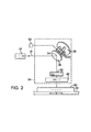
図2はFSM30の好適な実施形態を示しており、このFSM30は、レーザー出力14を受けるように配置され、ECB(エッチング回路基板)バイア穿孔、回路素子トリミング又は他の微小加工適用の目的でそれを高速位置決め器32及び対物レンズ42を通してワークピース50上のターゲット位置60へ偏向させる。FSM30は好適には、高速位置決め器32より高い周波数応答性を有する電歪アクチュエータを利用する制限された偏向ビーム位置決めステージの一部として実現される。FSM30は、鉛マグネシウムニオベイト(PMN)、電圧を変位に変換させるアクチュエータ22のような強誘電性のセラミックアクチュエータ材料によって湾曲する。PMN材料はより一般的な圧電アクチュエータ材料に似ているが、 1 パーセントより小さいヒステリシスと、高い電気機械変換効率をもち、幅広い作業および製造温度範囲を示し、永久偏光(polarization)を要求せず、そして小さい電気駆動電圧をもつ有用な機械的活性を提供する。 FIG. 2 shows a preferred embodiment of the
例示的なPMNアクチュエータ22は、PMN材料の40mm長さのシリンダについて約20ミクロンの制限された変位を有するが、5mm直径のシリンダについて、ミクロン当たり約210ニュートンの極めて高い剛性を有する。FSM30は、正三角形として配置された第1端部を有する3つのPMNアクチュエータ22へ歪み可能に連結されており、その正三角形の中心点とFSM30の中心点24とは一致している。PMNアクチュエータ22の第2端部は、X軸並進ステージ54に取り付けられた据え付け台26に機械的に連結されている。3つのPMNアクチュエータ22は好適には、FSM30の倒れ込み及び傾斜は、3自由度の構造を2自由度モードで使用することで実現される。3つのPMNアクチュエータ22は好適には、円周に沿って3つの活性領域に電気的に分割されたPMN材料の中空のシリンダとして形成される。1領域を作動させることによりそれは膨張又は収縮し、それによってFSM30は倒れ傾斜する。 The exemplary PMN actuator 22 has a limited displacement of about 20 microns for a 40 mm long cylinder of PMN material, but a very high stiffness of about 210 Newtons per micron for a 5 mm diameter cylinder. The
好適にはアクチュエータの三角形は、5mmの側辺を有し、約±4ミリラジアン(mRad)の角度に偏向さることができ、これは80mm対物レンズ42でワークピース50上に投影されたとき、レーザー出力14の±640ミクロンの偏向に変換される。例示的なFSM30では、パターン寸法を、レーザースポット寸法の約25ないし50倍までに制限する典型的な移動範囲の制限を設けても良く、その一方でFSM30の最大の周波数応答性は、パターン寸法をレーザースポット寸法の約15倍まで、典型的にはレーザースポット寸法の5〜10倍に制限するようより抑制的に制限しても良い。FSM30は、高速位置決め器32の例示的なガルバノメータ駆動のX及びY軸ミラーより高い周波数及び加速度で作動する。非統合型の位置決めシステムの例示的なFSM30は1,000mm/secより速い速度をもたらし、4,000mm/sec又はそれよりも速い速度とすることも可能であり、これらは典型的な統合型の位置決めシステムの速度の5〜10倍の速度である。非統合型の位置決めシステムの例示的なFSM30は、1,000×9.8m/sec2より大きい加速度をもたらし、30,000×9.8m/sec2又はそれより大きい加速度とすることも可能であり、これらは典型的な統合型の位置決めシステムの加速度の50〜100倍である。Preferably, the actuator triangle has a side of 5 mm and can be deflected to an angle of about ± 4 milliradians (mRad), which is the laser when projected onto the
特に、例示的なPMNアクチュエータ22は、約20μF(microFarad)の容量特性、1.0ΩのDCインピーダンス、5kHzにおける17Ωインピーダンスを有し、75ボルトの電圧駆動において3アンペア以上の電流を引き出す(draws)。FSM30を駆動する例示的なPMNアクチュエータ22は、約5kHzよりも大きい広信号帯域幅と、約8kHよりも大きい狭信号帯域幅と、約±0.5ミクロンの位置決め分解能をもつレーザー出力14を偏向させるための少なくとも約4mRadの偏向角度を有する。 In particular, the exemplary PMN actuator 22 has a capacitance characteristic of about 20 μF (microFarad), a DC impedance of 1.0 Ω, a 17 Ω impedance at 5 kHz, and draws more than 3 amperes at a voltage drive of 75 volts. . An exemplary PMN actuator 22 that drives
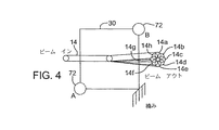
当業者には、任意の他の精密な高帯域幅のアクチュエータをミラーアクチュエータ22に利用できることは理解されよう。図3は、代替のFSM30を、ミラーアクチュエータ72A及び72B(包括的には、ミラーアクチュエータ72)用の例示的なミラー制御器64の例示的な制御回路と共に一部を断面図とし一部を概略図として示したものであり、ミラーアクチュエータ72は、好適には圧電(PZT)デバイスであり、圧電デバイスは、FSM30の角度を小さく変化させるために利用されて、レーザーシステム出力ビーム46の角度を小さく変化させ、その角度の小変化はワークピース50の表面のレーザースポット48の位置60を小さく変化させる。図4はFSM30の正面図であり、ミラーの歪みがレーザースポット48の位置60にどのように影響するかということを示すものである。 Those skilled in the art will appreciate that any other precise high bandwidth actuator can be utilized for the mirror actuator 22. FIG. 3 illustrates a partial cross-sectional view of an
図3、4を参照すると、PZTミラーアクチュエータ72を用いた例示的な実施形態が示されており、略方形のFSM30の1つのかど部は、撓むことはできるが圧縮又は延伸することはできない撓み性を有する基準構造体に固定されている。FSM30の2つの他のかど部は、正弦波に応答して圧電ミラーアクチュエータ72Aと72Bとによって駆動されてビーム進路18に小角度をもたらし、これはビーム位置決めシステム40の他の要素によって設定されたターゲット位置60上に重ねられたレーザースポット48のビーム位置に小変化を生じさせる。 Referring to FIGS. 3 and 4, an exemplary embodiment using a
好適な実施形態では、sin(a)の信号74は、1方向に角度変化を生じさせるために、圧電ミラーアクチュエータ72Aと72Bとを反対方向に駆動させ、sin(a+90度)の信号76は、最初の角度変化に対して90度の角度変化を生じさせるために、正弦(sine)によって同一方向に圧電ミラーアクチュエータ72Aと72Bとを駆動させる。レーザー出力14は、FSM30のおおよそ中心点で反射される。この結果、ミラー移動によってもたらされた小角度が走査レンズ42によって位置の変化に変換された後に、ワーク表面に円形運動が生じる。 In the preferred embodiment, sin (a)
レーザー穿孔作業では、好適な対物レンズの焦点長さは約50〜100mmであり、FSM30から走査レンズ42までの好適な距離はデザインの制約以内にあって実際上小さく、好適には、Zステージ(図示せず)がその正規の焦点高さにあるときに約300mmより小さく、更に好適には、100mmより小さい。好適なレーザーシステム10では、FSM30は、Xステージ54上の高速位置決め器32の上流側に取り付けられ、そして従来のビーム位置決めシステムの最終回転(final turn)ミラーに取って代わるものである。好適な実施形態では、FSM30は、オレゴン州ポートランド在のElecrto Scientific Industries社製のモデル5200又は5320に利用されているような既存のレーザー装置及び位置決めシステム40を容易にアップグレードして用いられており、また、従来のレーザーシステムのXステージ54上の最終回転ミラーと簡単に代えることができる。当業者には、FSM30は、ビーム進路18内に配置できる他、Xステージ54上以外の何れかの場所に取り付けできることは理解されよう。 For laser drilling operations, the focal length of the preferred objective lens is about 50-100 mm, and the preferred distance from the
当業者には、センター24のような旋回点の周りで2軸内においてFSM30の運動を制御するために種々の技術を代案として利用できることは認められるだろう。これらの技術は、ミラーの表面を変形させるために、歪み機構及びボイスコイルアクチュエータ、圧電、電わい又はPMNアクチュエータ材料の変形に依存する圧電アクチュエータ、及び圧電又は電わいアクチュエータを利用するFSM30を含む。ボイスコイルで作動するFSM30は、Bakerの米国特許第5,946,152号に記載されており、高周波数で動作するように適合させることができる。適当なボイスコイルにより作動するFSM30は、コロラド州のブルームフィールド在のBall Aerospace社及びカリフォルニア州のアーウ゛イン在のNewport社から入手可能である。適当な圧電アクチュエータは、ドイツ国カールスルーエ在のPhysik Instrumente(「PI」))社製のモデルS-330 Ultra-Fast Piezo Tip/Tilt Platformである。 Those skilled in the art will recognize that various techniques can be used as alternatives to control the movement of the
シミュレーションされたレーザースポット拡大(enlargement)の適用においては、レーザー制御器64は、トリミングプロフィール(profile)又は盲バイア穿孔プロフィールのような予定の工具進路に従うように統合型の位置決めシステムの高速位置決め器32及びステージ52、54に命令する一方で、ミラー制御器64は独立して、FSM30がレーザーシステム出力ビーム46のレーザースポット位置を小さな円運動又は振動のような所望のパターンで動かすようになす。この重複して自由進行するビーム移動又は振動は、レーザーシステム出力ビーム46のエネルギーを大区域上に分配し、工具進路に沿って幅広の切り口を有効に作る。有効な切り口幅は、前記パターンのパターン寸法とスポット直径との和に略等しい。ビーム移動はまた、広範囲に亘ってレーザーエネルギーを分散させ、或る時間内に所定の平均エネルギー密度で処理される区域を増大させる。 In a simulated laser spot enlargement application, the
FSM30に送られたミラー制御器64の命令は、統合型の位置決めシステムのステージ52、54及び高速位置決め器32にアドレスされた位置決め命令と統合されてはいないが、その位置決め命令に重ねられるので、多くの複雑さと出費が回避される一方、機能性及び処理量の著しい向上が達成される。また一方で、ミラー制御器64は、レーザー制御器62と協働し、特定のレーザー適用中にレーザーシステム出力ビーム46を所望のパターンで移動させ、あるいは統合型の位置決めシステムの特定の工具進路をもたらす。FSMの有効スポットパターンは、例えばトリミング加工を目的として、特定幅の切り口を得るためにパターン寸法を選択することができ及び/又は例えばバイア穿孔加工を目的として、特定の孔縁品質を得るために選択することができる。なお、当業者には、ミラー制御器64は、ユーザーが直接的にプログラミングすることができるが、レーザー制御器62と協働させる必要させる必要はなく、レーザー制御器62を介して制御する必要もないことは理解されよう。 The
コンピュータグラフィックスモデルは、上述したようなPZTアクチュエータによるFSM30の連続移動からもたらされる、ワーク表面におけるレーザースポット48個々の配置を示すために開発された。図5Bは、FSM30の移動によって向上した、図5Aの例示的な直線的な切り口を形成するための工具進路80のコンピュータモデルを示している。図5A及び5B(総称して図5)を参照すると、パラメータは、約18kHz のPRF、約25μmのスポット寸法、約50 mm/secの線速度(小さい回転円形パターンがワーク表面を横切る移動速度)、約2kHzの回転速度(円形パターンが回転している速度)、約30μmの回転適性(aptitude)((ビーム中心までの)円形パターンの直径)、約10μmの内径((円形パターンの中心までの)螺旋パターンの出発(starting)直径)、約150μmの外径((円形パターンの中心までの)螺旋パターンの端(end)直径)、及び約2回の繰り返し数(螺旋パターンが回転する回数)を含む。このモデルは、レーザーパルス速度を15〜20kHzの範囲内に支持するために、1kHz〜2.5kHzの回転速度(1回転当たり5〜15パルス)が実際的なパルスの重なりに望まれることを示している。 A computer graphics model was developed to show the individual placement of the laser spots 48 on the workpiece surface resulting from the continuous movement of the
再び図5を参照すると、ミラー増強された(mirror-enhanced)直線プロフィール82は、出力ビーム46のスポット直径86より大きい幅の切り口84を作る。この技術により、スポット直径86より幅の広い切り口がより少ないパスで形成されると同時に、加工の品質と集束された出力ビーム46を使用すること(即ちより幅の広いスポットを得るためにビーム焦点をぼかすことなしに)の他の利点を維持することができる。更に、ミラー増強された直線プロフィール82は、高い繰り返し速度の適用のために最も速い位置決め器32の帯域幅の能力を越えることができ、そして高速位置決め器32が、別法ではミラー増強された直線プロフィール82においてサブパターンを明確にすることが要求されるサブパターニング(sub patterning)とは対照的に、簡単な位置決め運動命令を保持することを可能となす。 Referring again to FIG. 5, the mirror-enhanced
図6Bは、FSM30の運動によって増強された、例示的なバイア形成用の螺旋工具進路90(図6A)のコンピュータモデルである。図6A、6B(総称して図6)を参照すれば、パラメータは、約15kHzのPRF、約15μmのスポット寸法、約30mm/secの線速度(小回転円形パターンがワーク表面を横切る移動速度)、約15kHzの回転速度(円形パターンが回転している速度)、約20μmの回転適性((ビーム中心までの)円形パターンの直径)、約10μmの内径((円形パターンの中心までの)螺旋パターンの出発直径)、約150μmの外径((円形パターンの中心までの)螺旋パターンの端直径)、及び約2回の繰り返し数(螺旋パターンが回転する回数)を含む。このモデルは、レーザーパルス速度を15〜20kHzの範囲内に支持するために1〜2.5kHzの回転速度(1回転当たり5〜15パルス)が実際的なパルスの重なりに望まれることを示している。 FIG. 6B is a computer model of an exemplary via forming spiral tool path 90 (FIG. 6A) augmented by the movement of
Qスイッチ付きCO2レーザーシステム10とPMN材料のFSM30を利用する例示的な実施形態では、CO2レーザーシステムはバイア孔当たり20〜30パルスをもつ30〜40kHzのPRFを利用する。FSM30は、1.0〜1.5kHzでレーザーシステム出力ビーム46を振動させるので、それは、孔が穿孔されるとき、完全な1回転をなし、穿孔時間は0.6〜1msより小さい時間となる。In an exemplary embodiment that utilizes a Q-switched CO 2 laser system 10 and
図6を参照すれば、盲バイアは、螺旋状の工具進路90に沿って隣接して重複する場所にスポット区域86を有するレーザーシステムの出力ビーム46を外周側に連続的に差し向けることによって形成される。ビーム46は、好適には、該システム10が該場所にカット深さを得るのに必要なビームパルスの数を放出するのに十分な速度で、各場所を通して連続的に動かされる。ビーム46が螺旋状の工具進路90に沿って進むにつれて、ターゲット材料は、少しずつ削り取られ、ビーム46が新しい切削場所に動かされる度に孔の寸法は増大する。孔の最終形状は典型的には、ビーム46が外周の円形進路に沿って移動したときに得られる。 Referring to FIG. 6, a blind via is formed by continuously directing the
ミラー増強されたバイア穿孔プロフィール92が出力ビーム46のスポット直径86より大きい切り口幅84をもたらし、結果として出来るバイアの直径94は、スポット寸法と同じ寸法の切り口幅から作られた螺旋の直径よりかなり大きくなることに留意されたい。この発明は、焦点はずれの状態で加工をすることに関連するビーム品質の問題なしに、所定の繰り返し速度での一連のレーザーパルススポット48が、より低いパルス速度での一連のより大直径のレーザーパルススポットとして現れることを可能にする。バイア直径又は切り口幅は典型的には25〜300μmの範囲にわたるが、1ミリメートル(mm)と同じか、又はそれより大きい直径又は幅をもつバイア又は切り口もまた望ましい。 The mirror-enhanced via
盲バイアを形成するための別の工具進路は、中心で出発しそして切り口幅84によって限定される漸増する半径の同心円を切断することになる。バイアの全直径はバイアを形成する同心円が領域の中心からより大きい距離をおいた個所で円形進路を進むにつれて増していく。代案として、このプロセスは所望の円周を限定しそして縁を中心にむけて処理していくことによって始めることができる。外側の螺旋処理は僅かに連続的となり、同心円の処理より速くなる傾向がある。しかし盲バイアは内方へ渦巻形に進めることによっても作ることができる。 Another tool path for forming a blind via would be to cut a concentric circle of increasing radius starting at the center and defined by the
当業者には、ワークピース50又は処理出力ビーム46の何れかを、他方の位置に対して固定又は移動することができることは理解されよう。好適な実施形態では、ワークピース50と処理出力ビーム46の両者は同時に移動する。多数の異なる基体上に、貫通孔バイア、種々の深さ及び直径を有する盲バイアを形成する例は、米国特許第5,593,606号に記載されている。他の工具進路のプロフィールを含む種々のバイア処理技術もまた、Dunsky等の米国特許第6,407,363号に記載されており、これは参考として明細書に含まれるものとする。当業者には、非円形バイアもまた同様のプロセスによって融除することができることは理解されよう。かかるバイアは例えば、正方形、方形、楕円形、スロット状又は他の表面幾何学的形態をもつことができる。 One skilled in the art will appreciate that either the
当業者にはまた、統合型の位置決めシステムを、小区域バイアを処理するために単一場所に差し向けることができ、また、非統合型のFSM30が、著しく滞留時間を長くすることなしに、及び工具進路90のような工具進路を実行するために統合型位置決めシステムを動かす複雑さなしに、出力ビーム46のスポット直径48より大きいバイア直径を作るために使用されることは、理解されるであろう。更に、縁の品質と底の均一性を含むバイア品質は、特に、レーザーシステム出力ビーム46の強度が比較的ガウス分布に従うときには大幅に改良することができる。 Those skilled in the art can also direct an integrated positioning system to a single location for handling small area vias and the
当業者には、本発明の上述の実施例の細部には、特許請求の範囲に記載した原理から逸脱することなく多くの変更を成し得ることは明らかであろう。従って本発明の範囲は特許請求の範囲によってのみ決定されるべきものである。 It will be apparent to those skilled in the art that many changes can be made in the details of the above-described embodiments of the invention without departing from the principles set forth in the claims. Accordingly, the scope of the invention should be determined only by the claims.
Claims (16)
一次的ビーム位置決めシステムから、ワークピースに対するレーザースポット位置の一次的相対移動を、制限された第1の速度及び加速度で与え、前記一次的ビーム位置決めシステムは、レーザー装置からワークピース上のレーザースポット位置にビーム位置決め経路を提供し、前記一次的相対移動は、一次的加工進路を定め、更に該加工方法は、
ビーム位置決め経路内に配置された二次的ビーム位置決めシステムから、ワークピースに対するレーザースポット位置の二次的相対移動を、第1の速度及び加速度よりも大きい第2の速度及び加速度で与え、該第2の速度及び加速度は速度が1,000mm/secより大きく、加速度が1,000×9.8m/sec 2 より大きいものであり、前記二次的相対移動は、一次的相対移動に重ねられるとともに、一次的加工進路に対して直角方向に規定されるパターン寸法がレーザースポット直径の15倍以下であるパターンを含み、一次的及び二次的相対移動は協働して、パターン寸法とスポット直径との和に相当する、一次的加工進路に沿った有効切り口幅をもたらすことを特徴とする加工方法。In a laser processing method in which each laser pulse has a laser spot diameter smaller than an effective cut width on the workpiece, the processing method is a method of laser processing an effective cut on a workpiece with a laser output pulse.
From the primary beam positioning system, a primary relative movement of the laser spot position relative to the workpiece is provided at a limited first velocity and acceleration, wherein the primary beam positioning system provides a laser spot position on the workpiece from the laser device. The primary relative movement defines a primary machining path, and the machining method further comprises:
From the secondary beam positioning system disposed in the beam positioning path, the secondary relative movement of the laser spot position with respect to the workpiece, given at a second speed and acceleration greater than the first speed and acceleration, said 2 speed and acceleration is greater than 1,000 mm / sec and acceleration is greater than 1,000 × 9.8 m / sec 2 , and the secondary relative movement is superimposed on the primary relative movement and The pattern dimension defined in a direction perpendicular to the primary processing path is less than or equal to 15 times the laser spot diameter, and the primary and secondary relative movements cooperate to form the pattern dimension and the spot diameter A machining method characterized by providing an effective cut width along the primary machining path corresponding to the sum of
一次的ビーム位置決めシステムから、ワークピースに対するレーザースポット位置の一次的相対移動を、制限された第1の速度及び加速度で与え、前記一次的ビーム位置決めシステムは、レーザー装置からワークピース上のレーザースポット位置にビーム位置決め経路を提供し、前記一次的相対移動は、一次的加工進路を定め、更に該加工方法は、 From the primary beam positioning system, a primary relative movement of the laser spot position relative to the workpiece is provided at a limited first velocity and acceleration, wherein the primary beam positioning system provides a laser spot position on the workpiece from the laser device. The primary relative movement defines a primary machining path, and the machining method further comprises:
ビーム位置決め経路内に配置され5kHzより大きい広信号帯域と、8kHzより大きい狭信号帯域幅を有する二次的ビーム位置決めシステムから、ワークピースに対するレーザースポット位置の二次的相対移動を、第1の速度及び加速度よりも大きい第2の速度及び加速度で与え、前記二次的相対移動は、一次的相対移動に重ねられるとともに、一次的加工進路に対して直角方向に規定されるパターン寸法がレーザースポット直径の15倍以下であるパターンを含み、一次的及び二次的相対移動は協働して、パターン寸法とスポット直径との和に相当する、一次的加工進路に沿った有効切り口幅をもたらすことを特徴とする加工方法。 A secondary relative movement of the laser spot position with respect to the workpiece from a secondary beam positioning system disposed in the beam positioning path and having a wide signal bandwidth greater than 5 kHz and a narrow signal bandwidth greater than 8 kHz is performed at a first speed. The secondary relative movement is superimposed on the primary relative movement, and a pattern dimension defined in a direction perpendicular to the primary machining path is a laser spot diameter. The primary and secondary relative movements together to produce an effective cut width along the primary machining path corresponding to the sum of the pattern dimensions and the spot diameter. A characteristic processing method.
一次的ビーム位置決めシステムから、ワークピースに対するレーザースポット位置の一次的相対移動を、制限された第1の速度及び加速度で与え、前記一次的ビーム位置決めシステムは、レーザー装置からワークピース上のレーザースポット位置にビーム位置決め経路を提供し、前記一次的相対移動は、一次的加工進路を定め、更に該加工方法は、 From the primary beam positioning system, a primary relative movement of the laser spot position relative to the workpiece is provided at a limited first velocity and acceleration, wherein the primary beam positioning system provides a laser spot position on the workpiece from the laser device. The primary relative movement defines a primary machining path, and the machining method further comprises:
ビーム位置決め経路内に配置され鉛マグネシウムニオベイト作動ミラー又は圧電作動ミラーを含む高速ステアリングミラーを有する二次的ビーム位置決めシステムから、ワークピースに対するレーザースポット位置の二次的相対移動を、第1の速度及び加速度よりも大きい第2の速度及び加速度で与え、前記二次的相対移動は、一次的相対移動に重ねられるとともに、一次的加工進路に対して直角方向に規定されるパターン寸法がレーザースポット直径の15倍以下であるパターンを含み、一次的及び二次的相対移動は協働して、パターン寸法とスポット直径との和に相当する、一次的加工進路に沿った有効切り口幅をもたらすことを特徴とする加工方法。 A secondary relative movement of the laser spot position relative to the workpiece from a secondary beam positioning system having a high speed steering mirror disposed in the beam positioning path and including a lead magnesium niobate actuating mirror or a piezoelectric actuating mirror, and a first velocity The secondary relative movement is superimposed on the primary relative movement, and a pattern dimension defined in a direction perpendicular to the primary machining path is a laser spot diameter. The primary and secondary relative movements together to produce an effective cut width along the primary machining path corresponding to the sum of the pattern dimensions and the spot diameter. A characteristic processing method.
並進ステージ位置決めシステムから、ワークピースに対するレーザースポット位置の、ステージ関連の相対的移動を、制限された並進ステージの速度及び加速度で与え、
高速位置決めシステムから、ワークピースに対するレーザースポット位置の高速相対的移動を、制限された高速の速度及び加速度で与え、前記高速位置決めシステムは並進ステージ位置決めシステムより高い加速度性能を有し、更に該加工方法は、
制限された第1の速度及び加速度でワークピースに対するレーザースポット位置の一次的相対的移動を与えるために、並進ステージ位置決めシステムと高速位置決めシステムとを統合することを含み、一次的ビーム位置決めシステムはビーム位置決め経路をレーザー装置からワークピース上のレーザースポット位置へ提供し、一次的相対的移動は一次的加工進路を定め、そして更に該加工方法は、
ビーム位置決め経路内に配置された高速ステアリングミラーから、ワークピースに対するレーザースポット位置の二次的相対的移動を、第1の速度及び加速度より大きい第2の速度及び加速度で与え、二次的相対的移動は一次的相対的移動上に重ねられているが、一次的相対的移動とは統合されておらず、かつ一次的加工進路に対して直角方向に規定されるパターン寸法がレーザースポット直径の15倍以下であるパターンを含み、一次的及び二次的相対移動は協働して、パターン寸法とスポット直径との和に相当する、一次的加工進路に沿った有効切り口幅をもたらすことを特徴とする加工方法。In a laser processing method in which each laser pulse has a laser spot diameter smaller than the effective cut width on the workpiece by laser output pulses, the processing method includes:
From the translation stage positioning system, give the stage-related relative movement of the laser spot position relative to the workpiece, with limited translation stage speed and acceleration,
A high speed positioning system provides high speed relative movement of the laser spot position with respect to the workpiece with limited high speed velocity and acceleration, the high speed positioning system having higher acceleration performance than a translation stage positioning system, and further comprising the processing method Is
The primary beam positioning system includes integrating a translation stage positioning system and a high speed positioning system to provide a primary relative movement of the laser spot position relative to the workpiece at a limited first velocity and acceleration. Providing a positioning path from the laser device to the laser spot position on the workpiece, the primary relative movement defines a primary processing path, and the processing method further comprises:
A secondary relative movement of the laser spot position relative to the workpiece is provided at a second velocity and acceleration greater than the first velocity and acceleration from a high speed steering mirror disposed in the beam positioning path, with a secondary relative The movement is superimposed on the primary relative movement, but is not integrated with the primary relative movement and the pattern dimension defined in the direction perpendicular to the primary machining path is 15 of the laser spot diameter. Including patterns that are less than or equal to twice, and the primary and secondary relative movements cooperate to provide an effective cut width along the primary machining path that corresponds to the sum of the pattern dimensions and the spot diameter. Processing method to do.
レーザー出力パルスをもたらすレーザー装置と、
ワークピースを移動させる並進ステージ位置決めシステムと、
レーザー出力パルスを受けるとともにビーム位置決め経路をワークピースに対して移動させる高速位置決めシステムと、
ビーム位置決め経路内であって、高速位置決めシステムの上流側に配置された二次的ビーム位置決めシステムと、を具えることを特徴とするシステム。A system using the method according to any one of claims 1 to 15 ,
A laser device for providing a laser output pulse;
A translation stage positioning system for moving the workpiece;
A high-speed positioning system that receives the laser output pulse and moves the beam positioning path relative to the workpiece;
A secondary beam positioning system disposed in the beam positioning path and upstream of the high speed positioning system.
Applications Claiming Priority (2)
| Application Number | Priority Date | Filing Date | Title |
|---|---|---|---|
| US34861302P | 2002-01-11 | 2002-01-11 | |
| PCT/US2003/000686 WO2003059568A1 (en) | 2002-01-11 | 2003-01-10 | Method for laser machining a workpiece with laser spot enlargement |
Publications (3)
| Publication Number | Publication Date |
|---|---|
| JP2005532908A JP2005532908A (en) | 2005-11-04 |
| JP2005532908A5 JP2005532908A5 (en) | 2008-04-17 |
| JP4340745B2 true JP4340745B2 (en) | 2009-10-07 |
Family
ID=23368777
Family Applications (1)
| Application Number | Title | Priority Date | Filing Date |
|---|---|---|---|
| JP2003559716A Expired - Lifetime JP4340745B2 (en) | 2002-01-11 | 2003-01-10 | Laser machining method for workpieces that expand the laser spot |
Country Status (9)
| Country | Link |
|---|---|
| JP (1) | JP4340745B2 (en) |
| KR (1) | KR100982677B1 (en) |
| CN (1) | CN1299873C (en) |
| AU (1) | AU2003214818A1 (en) |
| CA (1) | CA2469520A1 (en) |
| DE (1) | DE10392185T5 (en) |
| GB (1) | GB2397545B (en) |
| TW (1) | TW564196B (en) |
| WO (1) | WO2003059568A1 (en) |
Families Citing this family (22)
| Publication number | Priority date | Publication date | Assignee | Title |
|---|---|---|---|---|
| DE102004059721A1 (en) * | 2004-12-11 | 2006-05-04 | Carl Baasel Lasertechnik Gmbh & Co. Kg | Irrigation hose has several longitudinal discharge openings formed by sectional grooves in hose wall whereby flow limiter is arranged at inside portion of hose |
| CN100462181C (en) * | 2006-10-30 | 2009-02-18 | 西安交通大学 | Femto-second laser ture three-D micro-nano-processing center |
| US7663269B2 (en) * | 2006-12-13 | 2010-02-16 | A-Tech Corporation | High bandwidth linear actuator for steering mirror applications |
| DE102007012815A1 (en) | 2007-03-16 | 2008-09-18 | Sauer Gmbh Lasertec | Method and device for workpiece machining |
| US20090312859A1 (en) * | 2008-06-16 | 2009-12-17 | Electro Scientific Industries, Inc. | Modifying entry angles associated with circular tooling actions to improve throughput in part machining |
| TWI523720B (en) | 2009-05-28 | 2016-03-01 | 伊雷克托科學工業股份有限公司 | Acousto-optic deflector applications in laser processing of features in a workpiece, and related laser processing method |
| DE102009044316B4 (en) | 2009-10-22 | 2015-04-30 | Ewag Ag | Method for producing a surface and / or edge on a blank and laser processing device for carrying out the method |
| US8338745B2 (en) * | 2009-12-07 | 2012-12-25 | Panasonic Corporation | Apparatus and methods for drilling holes with no taper or reverse taper |
| KR101908002B1 (en) * | 2010-10-22 | 2018-12-19 | 일렉트로 싸이언티픽 인더스트리이즈 인코포레이티드 | Laser processing systems and methods for beam dithering and skiving |
| CN102069298A (en) * | 2010-12-20 | 2011-05-25 | 珠海市铭语自动化设备有限公司 | Laser cutting system for plates and cutting processing method thereof |
| CN102566590B (en) * | 2011-03-14 | 2014-03-26 | 北京国科世纪激光技术有限公司 | Intelligent adjusting system and method for optical element |
| CN103100797B (en) * | 2013-01-23 | 2015-09-09 | 刘茂珍 | Based on laser assisted microprocessing equipment and the method for adaptive optics |
| KR102154885B1 (en) * | 2013-02-13 | 2020-09-10 | 스미또모 가가꾸 가부시키가이샤 | Laser irradiation device and device of manufacturing laminate optical member |
| GB2511064A (en) | 2013-02-21 | 2014-08-27 | M Solv Ltd | Method of forming electrode structure for capacitive touch sensor |
| GB2514084B (en) * | 2013-02-21 | 2016-07-27 | M-Solv Ltd | Method of forming an electrode structure for capacitive touch sensor |
| EP2969372A4 (en) * | 2013-03-15 | 2016-11-16 | Electro Scient Ind Inc | Coordination of beam angle and workpiece movement for taper control |
| IT201600070259A1 (en) * | 2016-07-06 | 2018-01-06 | Adige Spa | Process of laser processing of a metal material with control of the position of the optical axis of the laser with respect to a flow of assistance gas, as well as a machine and computer program for carrying out such a process. |
| CN107876981B (en) * | 2017-11-20 | 2019-08-20 | 张家港初恒激光科技有限公司 | A kind of follow-on laser welding machining workstation |
| CN109579690A (en) * | 2018-12-04 | 2019-04-05 | 天津津航技术物理研究所 | A kind of high-precision angular displacement detecting device for fast anti-mirror image stabilization system |
| CN112122776A (en) * | 2020-09-23 | 2020-12-25 | 苏州科韵激光科技有限公司 | Nonlinear shape processing system and method based on high-speed rotating reflector |
| KR102497645B1 (en) * | 2021-06-23 | 2023-02-08 | 인하대학교 산학협력단 | Method of laser machine the mold surface |
| CN113897608A (en) * | 2021-10-23 | 2022-01-07 | 河南省锅炉压力容器安全检测研究院 | Laser surface strengthening processing equipment for valve sealing surface |
Family Cites Families (9)
| Publication number | Priority date | Publication date | Assignee | Title |
|---|---|---|---|---|
| JPS54116356A (en) * | 1978-03-03 | 1979-09-10 | Hitachi Ltd | Welding method by laser |
| FR2577052B1 (en) * | 1985-02-05 | 1988-09-09 | Bertin & Cie | METHOD AND DEVICE FOR MOVING THE POINT OF IMPACT OF A LASER BEAM ON A WORKPIECE |
| ATE152387T1 (en) * | 1991-01-17 | 1997-05-15 | United Distillers Plc | DYNAMIC LASER MARKING |
| JPH05209731A (en) * | 1992-01-31 | 1993-08-20 | Fanuc Ltd | Optical-axis adjusting method for laser robot |
| JP3060813B2 (en) | 1993-12-28 | 2000-07-10 | トヨタ自動車株式会社 | Laser processing equipment |
| JPH0885866A (en) * | 1994-09-16 | 1996-04-02 | Sumitomo Metal Mining Co Ltd | Production of ito sintered compact |
| US5847960A (en) * | 1995-03-20 | 1998-12-08 | Electro Scientific Industries, Inc. | Multi-tool positioning system |
| US5751585A (en) * | 1995-03-20 | 1998-05-12 | Electro Scientific Industries, Inc. | High speed, high accuracy multi-stage tool positioning system |
| AU2001251172A1 (en) * | 2000-03-30 | 2001-10-15 | Electro Scientific Industries, Inc. | Laser system and method for single pass micromachining of multilayer workpieces |
-
2003
- 2003-01-10 TW TW092100478A patent/TW564196B/en not_active IP Right Cessation
- 2003-01-10 WO PCT/US2003/000686 patent/WO2003059568A1/en active Application Filing
- 2003-01-10 AU AU2003214818A patent/AU2003214818A1/en not_active Abandoned
- 2003-01-10 JP JP2003559716A patent/JP4340745B2/en not_active Expired - Lifetime
- 2003-01-10 KR KR1020047010540A patent/KR100982677B1/en active IP Right Grant
- 2003-01-10 CN CNB038019914A patent/CN1299873C/en not_active Expired - Lifetime
- 2003-01-10 DE DE10392185T patent/DE10392185T5/en not_active Ceased
- 2003-01-10 CA CA002469520A patent/CA2469520A1/en not_active Abandoned
- 2003-01-10 GB GB0412827A patent/GB2397545B/en not_active Expired - Fee Related
Also Published As
| Publication number | Publication date |
|---|---|
| GB2397545A (en) | 2004-07-28 |
| TW200301718A (en) | 2003-07-16 |
| CA2469520A1 (en) | 2003-07-24 |
| CN1299873C (en) | 2007-02-14 |
| TW564196B (en) | 2003-12-01 |
| DE10392185T5 (en) | 2004-12-02 |
| AU2003214818A1 (en) | 2003-07-30 |
| KR100982677B1 (en) | 2010-09-17 |
| KR20040073542A (en) | 2004-08-19 |
| JP2005532908A (en) | 2005-11-04 |
| GB2397545B (en) | 2005-05-11 |
| CN1612793A (en) | 2005-05-04 |
| GB0412827D0 (en) | 2004-07-14 |
| WO2003059568A1 (en) | 2003-07-24 |
Similar Documents
| Publication | Publication Date | Title |
|---|---|---|
| US6706998B2 (en) | Simulated laser spot enlargement | |
| JP4340745B2 (en) | Laser machining method for workpieces that expand the laser spot | |
| JP2005532908A5 (en) | ||
| US6407363B2 (en) | Laser system and method for single press micromachining of multilayer workpieces | |
| JP4711393B2 (en) | Laser beam three-dimensional positioning apparatus and method | |
| JP4820071B2 (en) | Multi-beam micromachining system and method | |
| EP1910015B1 (en) | Via hole machining for microwave monolithic integrated circuits | |
| US20140263212A1 (en) | Coordination of beam angle and workpiece movement for taper control | |
| US8084706B2 (en) | System and method for laser processing at non-constant velocities | |
| JP5265375B2 (en) | Apparatus and method for X & Y two-dimensional cutting direction machining with set beam splitting using 45 degree beam splitting orientation | |
| US11232951B1 (en) | Method and apparatus for laser drilling blind vias | |
| JP3769942B2 (en) | Laser processing method and apparatus, and circuit forming method and apparatus for non-conductive transparent substrate | |
| JP2004526575A (en) | Ultraviolet laser ablation patterning method of fine structure in semiconductor | |
| KR20190025721A (en) | Laser processing apparatus and method for laser processing a workpiece | |
| WO2011148492A1 (en) | Laser processing method and laser processing machine | |
| JP4141809B2 (en) | Laser processing method | |
| CN111299859A (en) | Ultrafast laser non-taper cutting system and cutting method | |
| KR100664573B1 (en) | Laser Processing Apparatus and Method thereof | |
| JP2002346775A (en) | Device and method for laser beam machining | |
| Pique et al. | Laser direct-write micromachining | |
| JP2002079393A (en) | Laser beam irradiation device and method for laser beam machining |
Legal Events
| Date | Code | Title | Description |
|---|---|---|---|
| RD04 | Notification of resignation of power of attorney |
Free format text: JAPANESE INTERMEDIATE CODE: A7424 Effective date: 20040826 |
|
| A521 | Request for written amendment filed |
Free format text: JAPANESE INTERMEDIATE CODE: A523 Effective date: 20050615 |
|
| A621 | Written request for application examination |
Free format text: JAPANESE INTERMEDIATE CODE: A621 Effective date: 20050615 |
|
| A977 | Report on retrieval |
Free format text: JAPANESE INTERMEDIATE CODE: A971007 Effective date: 20071017 |
|
| A131 | Notification of reasons for refusal |
Free format text: JAPANESE INTERMEDIATE CODE: A131 Effective date: 20071113 |
|
| A524 | Written submission of copy of amendment under article 19 pct |
Free format text: JAPANESE INTERMEDIATE CODE: A524 Effective date: 20080213 |
|
| A524 | Written submission of copy of amendment under article 19 pct |
Free format text: JAPANESE INTERMEDIATE CODE: A524 Effective date: 20080213 |
|
| A131 | Notification of reasons for refusal |
Free format text: JAPANESE INTERMEDIATE CODE: A131 Effective date: 20081014 |
|
| A601 | Written request for extension of time |
Free format text: JAPANESE INTERMEDIATE CODE: A601 Effective date: 20090114 |
|
| A521 | Request for written amendment filed |
Free format text: JAPANESE INTERMEDIATE CODE: A523 Effective date: 20090119 |
|
| A602 | Written permission of extension of time |
Free format text: JAPANESE INTERMEDIATE CODE: A602 Effective date: 20090121 |
|
| TRDD | Decision of grant or rejection written | ||
| A01 | Written decision to grant a patent or to grant a registration (utility model) |
Free format text: JAPANESE INTERMEDIATE CODE: A01 Effective date: 20090512 |
|
| A01 | Written decision to grant a patent or to grant a registration (utility model) |
Free format text: JAPANESE INTERMEDIATE CODE: A01 |
|
| A61 | First payment of annual fees (during grant procedure) |
Free format text: JAPANESE INTERMEDIATE CODE: A61 Effective date: 20090610 |
|
| FPAY | Renewal fee payment (event date is renewal date of database) |
Free format text: PAYMENT UNTIL: 20120717 Year of fee payment: 3 |
|
| R150 | Certificate of patent or registration of utility model |
Ref document number: 4340745 Country of ref document: JP Free format text: JAPANESE INTERMEDIATE CODE: R150 Free format text: JAPANESE INTERMEDIATE CODE: R150 |
|
| FPAY | Renewal fee payment (event date is renewal date of database) |
Free format text: PAYMENT UNTIL: 20120717 Year of fee payment: 3 |
|
| FPAY | Renewal fee payment (event date is renewal date of database) |
Free format text: PAYMENT UNTIL: 20130717 Year of fee payment: 4 |
|
| R250 | Receipt of annual fees |
Free format text: JAPANESE INTERMEDIATE CODE: R250 |
|
| R250 | Receipt of annual fees |
Free format text: JAPANESE INTERMEDIATE CODE: R250 |
|
| R250 | Receipt of annual fees |
Free format text: JAPANESE INTERMEDIATE CODE: R250 |
|
| R250 | Receipt of annual fees |
Free format text: JAPANESE INTERMEDIATE CODE: R250 |
|
| R250 | Receipt of annual fees |
Free format text: JAPANESE INTERMEDIATE CODE: R250 |
|
| R250 | Receipt of annual fees |
Free format text: JAPANESE INTERMEDIATE CODE: R250 |
|
| R250 | Receipt of annual fees |
Free format text: JAPANESE INTERMEDIATE CODE: R250 |
|
| R250 | Receipt of annual fees |
Free format text: JAPANESE INTERMEDIATE CODE: R250 |
|
| R250 | Receipt of annual fees |
Free format text: JAPANESE INTERMEDIATE CODE: R250 |
|
| R250 | Receipt of annual fees |
Free format text: JAPANESE INTERMEDIATE CODE: R250 |
|
| R250 | Receipt of annual fees |
Free format text: JAPANESE INTERMEDIATE CODE: R250 |
|
| EXPY | Cancellation because of completion of term |