JP4339959B2 - Modulator, demodulator and transmission system for OFDM transmission - Google Patents
Modulator, demodulator and transmission system for OFDM transmission Download PDFInfo
- Publication number
- JP4339959B2 JP4339959B2 JP14224499A JP14224499A JP4339959B2 JP 4339959 B2 JP4339959 B2 JP 4339959B2 JP 14224499 A JP14224499 A JP 14224499A JP 14224499 A JP14224499 A JP 14224499A JP 4339959 B2 JP4339959 B2 JP 4339959B2
- Authority
- JP
- Japan
- Prior art keywords
- phase
- ofdm
- pilot
- carrier
- data
- Prior art date
- Legal status (The legal status is an assumption and is not a legal conclusion. Google has not performed a legal analysis and makes no representation as to the accuracy of the status listed.)
- Expired - Lifetime
Links
Images


Landscapes
- Synchronisation In Digital Transmission Systems (AREA)
Description
【0001】
【発明の属する技術分野】
本発明は、直交周波数分割多重(以下「OFDM」という)伝送に用いる変調装置および復調装置に関し、特に位相補正技術に関するものである。
【0002】
【従来の技術】
近年、移動体向けデジタル音声放送や地上系デジタルテレビ放送などにおいてOFDM技術を用いた伝送方式が注目されている。このOFDM技術はマルチキャリア変調方式の一種で、送信すべきデータ(送信データ)を隣接間で互いに直交する多数のサブキャリアに割り当て、さらに逆フーリエ変換することにより時間領域のデジタル変調信号に変換してOFDM信号を生成する。OFDM伝送においては、送信側で送信データに前述の処理を施して生成したOFDM信号を受信側に伝送する。そして受信側では、伝送されたOFDM信号に送信側で施された処理と逆の処理を施すことにより送信データを再生するものである。OFDM信号は、サブキャリアに分割された各々のデータの周期が長くなるため、マルチパスなどの遅延波の影響を受け難い特徴を有している。
【0003】
OFDM復調は、直交検波器によりベースバンド帯域にダウンコンバートしたOFDM信号を、高速フーリエ変換(以下「FFT」という)回路を用いてフーリエ変換処理を施すことで行う。このとき、直交検波器では送受信間での正確な周波数同期の確立が必要であり、またFFTでは受信したOFDM信号から1シンボル区間を規定のクロックで正確に取り込み、フーリエ変換することで各サブキャリアの位相と振幅情報を得る必要がある。
【0004】
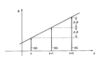
送受信のそれぞれにおけるOFDM信号に関して、周波数ずれおよび正確に1シンボル区間を取り込めない時間ずれがある場合、各サブキャリアは位相回転を起こし、送信データを再生できない。このように、OFDM復調には正確な周波数同期、シンボル同期およびクロック同期が必要であり、従来のOFDM復調装置では同期用シンボルを用いて周波数同期、シンボル同期、およびクロック同期のそれぞれを確立する必要がある。このために、OFDM信号Soは、図11に示すように、それぞれ複数(・・・、k、k+1、k+2、・・・)のサブキャリアSCより成る複数のOFDMシンボルOSにより伝送フレームが構成され、フレーム毎に同期用シンボルが挿入されて伝送される。同図において、縦軸は位相φ、横軸はサブキャリア周波数Fを表している。そして△φは隣接サブキャリア間の位相誤差を示している。
【0005】
更に、図12に示すように、n(nは1以上の整数)個のOFDMシンボルOSの先頭に同期用シンボルRSとしてヌルシンボルを挿入して1つの伝送フレームFrを構成しており、このヌルシンボルを連続して検出することで同期を確立する。なお、ヌルシンボルはOFDM変調したものでなくても良く、同期情報が得られやすい信号を用いることができる。つまり、OFDM信号Soは、ランダムノイズ状の波形となるため、これらの同期情報を時間軸波形から直接得ることが困難であるからである。そのため、周波数同期のためには正弦波形の信号を、クロック同期のためにはクロック成分が抽出しやすい振幅シフトキーイング(ASK)方式により変調された波形信号を用いることができる。
【0006】
図13を参照して、このように構成されたOFDM信号の概念について説明する。OFDM信号の周波数領域での状態SFを図左半部に、時間領域での状態STを図右半部に模式的に示している。周波数軸信号SFは、各OFDMシンボルOS1〜OSnのそれぞれが、周波数軸F上に多数のサブキャリアSCを直交するように配置して構成される。この周波数軸信号SFを逆フーリエ変換してOFDM変調することによって、時間軸信号STが生成される。各サブキャリアSCは送信側で一次変調された間隔P=1/PS(Hz)でサブキャリアを配置し、逆フーリエ変換してシンボル期間PS(sec)の時間軸T上の信号STに変換される。
【0007】
送信側から伝送する場合はこのOFDMシンボルOSと同期基準シンボルRSでOFDM信号の送信フレームを構成して伝送する。同期基準シンボルRSはOFDM変調したシンボルである必要はなく、同期処理に使いやすい波形の信号であれば良い。
【0008】
受信側では、入力された時間軸上の信号STから同期用基準シンボルRSだけを取り出して同期制御を行う。OFDMシンボルOSはシンボル期間PS毎に切り出され、更にフーリエ変換を施されて周波数軸上の信号SFに変換されることにより、OFDMシンボルOSが各サブキャリアSCに分離される。その後、分離された各サブキャリアSCに対して一次復調(データ復調)が施されることにより、受信データが得られる即ち送信データが再生される。このようなOFDM信号の復調処理において同期を正確に維持するには定期的に同期基準シンボルを伝送する必要が有る。
【0009】
以下に、図14を参照して、このような従来のOFDM復調装置の一例として、特開平8−102769号公報に開示されているOFDM復調装置について説明する。OFDM復調装置DMCは、A/D変換器101、クロック同期確立器102、直交検波器103、周波数同期確立器104、高速フーリエ変換器(FFT)105、シンボル同期確立器106、および一次復調器107を有する。送信側より伝送されたOFDM信号So’は、A/D変換器101、クロック同期確立器102、周波数同期確立器104、およびシンボル同期確立器106のそれぞれに供給される。
【0010】
クロック同期確立器102は、OFDM信号So’中の同期シンボルRSに基づいて、OFDM信号の送受信間におけるサンプリングクロックの同期ずれを検出する。クロック同期確立器102は、更に検出された同期ずれを補正して同期確立させたサンプリングクロック信号Sscを生成してA/D変換器101に出力する。A/D変換器101は、このサンプリングクロック信号Sscに基づいて、アナログのOFDM信号So’をサンプリングクロック成分の同期が確立されたデジタルのOFDM信号Soに変換して、直交検波器103に出力する。
【0011】
周波数同期確立器104は、OFDM信号So’中の同期シンボルRSに基づいて、送受信間に於けるキャリア信号の周波数の同期ずれを検出して、同期確立させた周波数信号Scfを生成して直交検波器103に出力する。直交検波器103は、この周波数信号Scfに基づいて、サンプリングクロック成分の同期確立されたデジタルのOFDM信号SoのOFDMシンボルOS(サブキャリアSC)を直交検波して、中間周波数帯域からベースバンド帯域のOFDM信号Sbに変換して、高速フーリエ変換器105に出力する。このベースバンド帯域のOFDM信号Sbが、キャリア信号の周波数成分の同期確立と併せて、サンプリングクロック成分の同期確立がされていることは言うまでもない。
【0012】
シンボル同期確立器106は、OFDM信号So’中の同期シンボルRSに基づいて、送受信間におけるシンボル時間窓の同期ずれを検出して、同期確立させたシンボル時間窓信号Sstを生成し、同信号Sstを高速フーリエ変換器105に出力する。高速フーリエ変換器105は、シンボル時間窓信号Sstに基づいて、ベースバンド帯域のOFDM信号Sbに高速フーリエ変換処理を施す。そして、高速フーリエ変換器105は、個々のOFDMシンボルOS毎に、時間領域の信号から周波数領域の各サブキャリアSCに分離して、シンボル同期の確立したサブキャリア信号Scを生成し、そして同信号Scを一次復調器107に出力する。このサブキャリア信号Scは、シンボル窓の同期確立に併せて、サンプリングクロック同期およびキャリア信号の周波数同期が確立されている。
【0013】
一次復調器107は、高速フーリエ変換器105から出力されたサブキャリア信号Scを各サブキャリア毎に復調して送信データSdを再生する。
【0014】
従来のOFDM復調器DMCは、直交検波器103によりベースバンド帯域にダウンコンバートしたOFDM信号Sbに、高速フーリエ変換(FFT)器105を用いてフーリエ変換演算を施す。このとき、直交検波器103では送受信間での正確な周波数同期確立が必要であり、またFFTでは受信したOFDM信号から1シンボル区間を規定のクロックで正確に取り込み、フーリエ変換することで各サブキャリアの位相と振幅情報を得る。
【0015】
【発明が解決しようとする課題】
OFDM復調器側においては、サンプリングクロック、キャリア周波数、およびFFTシンボル窓時間に関して、送信側におけるのと同一の条件を正確に再現してデータ処理を行う必要がある。つまり、OFDM復調時には、サンプリングクロック、キャリア周波数、およびシンボル時間窓の同期を確立しなければならない。これに対して、従来のOFDM復調装置では所定の間隔で間欠的に挿入される同期用シンボルを検出してシンボル同期およびクロック同期を確立している。この場合同期を確立するまでに数フレーム分の同期用シンボルの検出が必要であり、その間のOFDMシンボルは正確に復調できない。しかし、送受信間での同期ずれは、例えば伝送環境の変化によって容易に生じて、クロックずれ、周波数ずれ、および時間窓のずれを招く。これらのずれが生じている場合に、OFDM変調を行ったシンボルの各キャリアは、送信時の位相からこれらのずれに相当する量だけ位相回転を生じる。各サブキャリアの位相には情報(送信データ)が割り当てられているため、送信データが誤って再生されてしまう。
【0016】
これらのずれに対しては、同期用基準シンボルからその情報を検出して、サンプリングクロックずれ、キャリア周波数ずれ、シンボル時間窓ずれをそれぞれの誤差信号としてフィードバックして、逐一調整(同期確立)して同期をとっている。そのため、これらのずれが生じた時点で復調したOFDMシンボルのサブキャリアには位相回転誤差が生じているため、送信データが誤って再生されてしまう。更に、所定の間隔で連続的に同期シンボルを検出できないと、安定した同期を確立することができないため、バースト状に送信されるOFDMシンボルを正確に復調することが非常に困難である。
【0017】
それ故に、本発明は、上記問題を解決すべくなされたものであって、送受信間で周波数ずれや時間ずれがあるような場合でも、各サブキャリアの位相誤差を補正し、OFDMシンボルの復調を可能にする、OFDM伝送のための変調装置および復調装置を提供することを目的とする。
【0018】
【課題を解決するための手段および発明の効果】
上記のような目的を達成するために、本発明は、以下に示すような特徴を有している。
【0019】
第1の発明は、複数のデータキャリアと複数のパイロットキャリアとを含む複数のサブキャリアで構成される複数のOFDMシンボルから生成されたOFDM信号を受信するOFDM復調装置であって、
前記受信したOFDM信号を前記OFDMシンボル毎にフーリエ変換することにより前記複数のサブキャリアへと分離して、各サブキャリアの位相と振幅を求めるサブキャリア分離手段と、
前記複数のサブキャリアから前記複数のパイロットキャリアの位置を検出するパイロットキャリア位置検出手段と、
前記複数のパイロットキャリアはそれぞれ既知の位相と振幅が割り当てられており、前記パイロットキャリア毎の送受信間の位相差を、各パイロットキャリアにおける前記受信したOFDM信号から求めた位相と前記既知の位相との差を求めることにより検出する位相差検出手段と、
送受信間の時間ずれによって発生し且つ周波数に比例する位相回転により、隣接するサブキャリア間に生じる送受信の位相差の変化量を、前記パイロットキャリアの位相差に基づいて算出する位相変化量算出手段と、
前記複数のデータキャリアについて、前記データキャリア毎の位相補正量を前記変化量に基づいて算出する位相補正量算出手段と、
前記位相補正量に基づいて前記データキャリア毎に前記受信したOFDM信号から求めた位相を補正する位相補正手段とを備えている。
【0020】
上記のような第1の発明によれば、パイロットキャリアの送受信間位相差が検出され、この位相差に基づいてキャリア周波数に対する送受信間位相回転量の変化量が算出され、この変化量に基づいて各サブキャリアの位相補正量が算出されるため、この位相補正量は各サブキャリアの絶対位相誤差(送受信間の位相誤差)に対応する。したがって、サブキャリアに対しQPSKやQAM変調のような絶対位相変調が行われているOFDM信号に対しても、各サブキャリアの位相誤差を補正して正しく復調することができる。
【0021】
第2の発明は、第1の発明において、
前記位相変化量算出手段は、第1のパイロットキャリアにおける位相差と前記第1のパイロットキャリアと連続する第2のパイロットキャリアにおける位相差の差を、前記第1のパイロットキャリアと前記第2のパイロットキャリアの周波数の差で割ることにより前記変化量を算出する。
【0022】
第3の発明は、第2の発明において、
前記位相変化量算出手段は、第1のパイロットキャリアにおける位相差と前記第1のパイロットキャリアと連続する第2のパイロットキャリアにおける位相差の差を、前記第1のパイロットキャリアと前記第2のパイロットキャリアの周波数の差で割ることにより前記変化量を算出する。
【0023】
第4の発明は、第1の発明において、
前記位相変化量算出手段は、縦軸を位相差、横軸を周波数とした2次元平面上に配置した第1のパイロットキャリアの位相差及び周波数と前記第1のパイロットキャリアと連続する第2のパイロットキャリアの位相差及び周波数とを直線近似し、前記直線の傾きから前記変化量を算出する。
【0024】
第5の発明は、第1の発明において、
前記位相変化量算出手段は、1組のパイロットキャリア間の位相差の差を前記1組のパイロットキャリア間の周波数の差で割る演算を、複数のパイロットキャリアの組について行い、前記演算の結果を平均することにより前記変化量を算出する。
第6の発明は、第1の発明において、
前記OFDM復調装置は、
前記位相補正後のデータキャリアを復調するデータ復調手段をさらに備えている。
【0025】
第7の発明は、第1の発明において、
前記OFDM信号は、バースト状に入力される。
【0026】
第8の発明は、
複数のデータキャリアと複数のパイロットキャリアとを含む複数のサブキャリアで構成される複数のOFDMシンボルから生成されたOFDM信号を受信して復調するOFDM復調方法であって、
前記受信したOFDM信号を前記OFDMシンボル毎にフーリエ変換することにより前記複数のサブキャリアへと分離して、各サブキャリアの位相と振幅を求めるステップと、
前記複数のサブキャリアから前記複数のパイロットキャリアの位置を検出するステップと、
前記複数のパイロットキャリアはそれぞれ既知の位相と振幅が割り当てられており、前記パイロットキャリア毎の送受信間の位相差を各パイロットキャリアにおける前記受信したOFDM信号から求めた位相と前記既知の位相との差を求めることにより検出するステップと、
送受信間の時間ずれによって発生し且つ周波数に比例する位相回転により、隣接するサブキャリア間に生じる送受信の位相差の変化量を、前記パイロットキャリアの位相差に基づいて算出するステップと、
前記複数のデータキャリアについて、前記データキャリア毎の位相補正量を前記変化量に基づいて算出するステップと、
前記位相補正量に基づいて前記データキャリア毎に前記受信したOFDM信号から求めた位相を補正するステップとを含む。
【0027】
第9の発明は、
複数のデータキャリアと複数のパイロットキャリアとを含む複数のサブキャリアで構成される複数のOFDMシンボルから生成されたOFDM信号を送受信するOFDM伝送システムであって、
OFDM送信装置とOFDM受信装置とを備え、
前記OFDM送信装置は、
前記複数のパイロットキャリアにそれぞれ既知の位相と振幅を割り当て、前記複数のデータキャリアにそれぞれ送信データに応じた位相と振幅を割り当てる変調手段と、
前記OFDMシンボル毎に前記複数のサブキャリアを逆フーリエ変換することにより前記OFDM信号を生成するOFDM信号生成手段とを備え、
前記OFDM受信装置は、
前記受信したOFDM信号を前記OFDMシンボル毎にフーリエ変換することにより前記複数のサブキャリアへと分離して、各サブキャリアの位相と振幅を求めるサブキャリア分離手段と、
前記複数のサブキャリアから前記複数のパイロットキャリアの位置を検出するパイロットキャリア位置検出手段と、
前記複数のパイロットキャリアはそれぞれ既知の位相と振幅が割り当てられており、前記パイロットキャリア毎の送受信間の位相差を各パイロットキャリアにおける前記受信したOFDM信号から求めた位相と前記既知の位相との差を求めることにより検出する位相差検出手段と、
送受信間の時間ずれによって発生し且つ周波数に比例する位相回転により、隣接するサブキャリア間に生じる送受信の位相差の変化量を、前記パイロットキャリアの位相差に基づいて算出する位相変化量算出手段と、
前記複数のデータキャリアについて、前記データキャリア毎の位相補正量を前記変化量に基づいて算出する位相補正量算出手段と、
前記位相補正量に基づいて前記データキャリア毎に前記受信したOFDM信号から求めた位相を補正する位相補正手段とを備えている。
【0028】
第10の発明は、
同一の位相及び振幅の割り当てられた複数のパイロットキャリアと、周波数軸方向に差動変調された複数のデータキャリアとを含む複数のサブキャリアで構成される複数のOFDMシンボルから生成されたOFDM信号を受信するOFDM復調装置であって、
前記受信したOFDM信号を前記OFDMシンボル毎にフーリエ変換することにより前記複数のサブキャリアへと分離して、各サブキャリアの位相と振幅を求めるサブキャリア分離手段と、
送受信間の時間ずれによって発生し且つ周波数に比例する位相回転により、隣接するサブキャリア間に生じる送受信の位相差の変化量を、前記複数のパイロットキャリア間の位相に基づいて算出する位相変化量算出手段と、
前記複数のデータキャリアに対して、各データキャリアの位相と前記各データキャリアを差動復調する際の基準となる隣接するサブキャリアの位相との差である隣接位相差を算出する隣接位相差算出手段と、
前記複数のデータキャリアの前記隣接位相差を前記変化量に基づいて補正する位相補正手段とを備えている。
【0029】
上記のような第9の発明によれば、受信されたパイロットキャリアの位相に基づいてサブキャリア間の位相補正量が求められ、パイロットキャリアの送受信間の位相差は求められない。したがって、サブキャリアに対し周波数方向の差動変調が行われているOFDM信号に対しては、簡単な構成で、サブキャリア間の位相差の誤差を補正して正しく復調することができる。
【0030】
第11の発明は、第10の発明において、
前記位相変化量算出手段は、第1のパイロットキャリアにおける位相と前記第1のパイロットキャリアと連続する第2のパイロットキャリアにおける位相の差を、前記第1のパイロットキャリアと前記第2のパイロットキャリアの周波数の差で割ることにより前記変化量を算出する。
【0031】
第12の発明は、第10の発明において、
前記位相補正手段は、前記隣接位相差から前記変化量を引くことにより前記隣接位相差を補正する。
【0032】
第13の発明は、第10の発明において、
前記位相変化量算出手段は、縦軸を位相、横軸を周波数とした2次元平面上に配置した第1のパイロットキャリアの位相及び周波数と前記第1のパイロットキャリアと連続する第2のパイロットキャリアの位相及び周波数とを直線近似し、前記直線の傾きから前記変化量を算出する。
【0033】
第14の発明は、第10の発明において、
前記位相変化量算出手段は、1組のパイロットキャリア間の位相の差を前記1組のパイロットキャリア間の周波数の差で割る演算を、複数のパイロットキャリアの組について行い、前記演算の結果を平均することにより前記変化量を算出する。
第15の発明は、第10の発明において、
前記OFDM復調装置は、
前記位相補正後のデータキャリアを復調するデータ復調手段をさらに備えている。
【0034】
第16の発明は、第10の発明において、
前記OFDM信号は、バースト状に入力される。
【0035】
第17の発明は、
同一の位相及び振幅の割り当てられた複数のパイロットキャリアと、周波数軸方向に差動変調された複数のデータキャリアとを含む複数のサブキャリアで構成される複数のOFDMシンボルから生成されたOFDM信号を受信して復調するOFDM復調方法であって、
前記受信したOFDM信号を前記OFDMシンボル毎にフーリエ変換することにより前記複数のサブキャリアへと分離して、各サブキャリアの位相と振幅を求めるステップと、
送受信間の時間ずれによって発生し且つ周波数に比例する位相回転により、隣接するサブキャリア間に生じる送受信の位相差の変化量を、前記複数のパイロットキャリア間の位相に基づいて算出するステップと、
前記複数のデータキャリアに対して、各データキャリアの位相と前記各データキャリアを差動復調する際の基準となる隣接するサブキャリアの位相との差である隣接位相差を算出するステップと、
前記複数のデータキャリアの前記隣接位相差を前記変化量に基づいて補正するステップとを備えている。
【0036】
第18の発明は、
同一の位相及び振幅の割り当てられた複数のパイロットキャリアと、周波数軸方向に差動変調された複数のデータキャリアとを含む複数のサブキャリアで構成される複数のOFDMシンボルから生成されたOFDM信号を送受信するOFDM伝送システムであって、
OFDM送信装置とOFDM受信装置とを備え、
前記OFDM送信装置は、
前記複数のパイロットキャリアにそれぞれ同一の位相及び振幅を割り当て、前記複数のデータキャリアにそれぞれ送信データに応じた隣接するサブキャリアの位相と振幅の差を有する位相と振幅を割り当てる変調手段と、
前記OFDMシンボル毎に前記複数のサブキャリアを逆フーリエ変換することにより前記OFDM信号を生成するOFDM信号生成手段とを備え、
前記OFDM受信装置は、
前記受信したOFDM信号を前記OFDMシンボル毎にフーリエ変換することにより前記複数のサブキャリアへと分離して、各サブキャリアの位相と振幅を求めるサブキャリア分離手段と、
送受信間の時間ずれによって発生し且つ周波数に比例する位相回転により、隣接するサブキャリア間に生じる送受信の位相差の変化量を、前記複数のパイロットキャリア間の位相に基づいて算出する位相変化量算出手段と、
前記複数のデータキャリアに対して、各データキャリアの位相と前記各データキャリアを差動復調する際の基準となる隣接するサブキャリアの位相との差である隣接位相差を算出する隣接位相差算出手段と、
前記複数のデータキャリアの前記隣接位相差を前記変化量に基づいて補正する位相補正手段とを備えている。
【0064】
【発明の実施の形態】
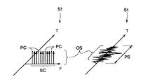
図2を参照して、先ず、本発明に係るOFDM信号およびその変調と復調の基本概念について説明する。OFDM信号の周波数領域での状態Sfが図左半部に、時間領域での状態Stが図右半部に模式的に示されている。周波数軸信号Sfは、周波数軸F上に直交するように配置された多数のサブキャリアSCの間に、パイロットキャリアPCと呼ばれる既知の位相を持つサブキャリアが埋め込まれて構成される。つまり、各OFDMシンボルOSを構成する複数のサブキャリアSCの内、所定の間隔のサブキャリアSCのそれぞれに既知の位相を与えて、この既知の位相を有するサブキャリアSCをパイロットキャリアPCとする。図2に示すように、本発明に係るOFDM信号Soは同期シンボルRSを必要としない構成である。
【0065】
図15に示すように、OFDM信号を用いたデータ伝送システムにおいて、送信側では、送信装置120内に含まれるOFDM変調装置121が次のようにしてOFDM信号を生成する。すなわち、まず、送信すべきデータ(送信データ)を複数のサブキャリアに割り当てると共にそれらのサブキャリアの間にパイロットキャリアPCを挿入することにより、伝送に使用されるサブキャリアSCを生成する。次に、パイロットキャリアの埋め込まれたこのサブキャリアSCに対してシンボル期間毎に逆フーリエ変換を施すことにより、時間領域信号Stを生成する。この時間領域信号Stは、変調された後にOFDM信号So’として伝送路130を介して送信装置120から受信装置140へと伝送される。受信側では、このOFDM信号So’を受信して、受信装置140に含まれるOFDM復調装置141がこのOFDM信号So’から次のようにして受信データを得る。すなわち、まず、このOFDM信号So’を復調してベースバンド信号である時間領域信号Stを得る。次に、この時間領域信号Stをシンボル期間PS毎に切り出し、切り出された時間領域信号Stにフーリエ変換を施して周波数軸F上の各サブキャリアSCに分離する。分離後、パイロットキャリアPCの位相からそのOFDMシンボル内の位相回転誤差を推定し、各サブキャリアSCの位相誤差を補償する。この位相誤差の補償された各サブキャリアの位相と振幅を求めることにより受信データを得る。
【0066】
このように本発明においては、同期ずれによる位相誤差を補正しているので、バースト状に複数のOFDMシンボルOSが送信される場合に、個々のOFDMシンボルOSを正しく復調できる。
【0067】
更に、OFDMシンボルOS自体に埋め込まれたパイロットキャリアPCに基づいて、同期ずれによる位相誤差を補償できるので、同期検出部の検出精度が劣っている、或いは同期検出部が無くても、高精度にデータを復調できる。
【0068】
また、本発明は図12および図13に示した従来のOFDM信号のようにフレーム構成で送信される場合にも適用できる。つまり、フレームを構成する各シンボル内にパイロットキャリアPCを埋め込むことにより、シンボル単位での同期ずれを補正できるので、OFDMシンボルが連続的に入力される場合にも正しく同期補正できる。
【0069】
後に詳述するが、同期基準シンボルRSに基づいてある程度同期をとった後、同期確立器で追い込めないずれに関して位相補償をかけて、さらに復調の精度を上げることができる。本発明が、同期シンボルRSを含む従来のOFDM信号にも適用できることは、後ほど図9を参照して詳しく説明する。
【0070】
図3を参照して、図2に示したOFDM周波数軸信号SfにおけるサブキャリアSCの詳細について更に説明する。周波数軸F上に配置された多数のサブキャリアSCの内、所定のサブキャリアに基準位相となる所定の複素数を割り当て、これをパイロットキャリアPC(点線の矢印で表示)とする。パイロットキャリアPCに割り当てる複素数は、例えば(1,0)などを用いる。ただし、実部iおよび虚部qからなる複素数を“(i,q)”と表記するものとする。パイロットキャリアPCは、例えば一定周波数間隔のサブキャリアSCに割り当てられる。或いは、各パイロットキャリアPCの間に入るサブキャリアSCの数(つまり、サブキャリア間隔)が1,3,5,・・・のように、一定の増分で増加する周波数間隔のサブキャリアSCをパイロットキャリアPCに割り当ててもよい。さらに所定のPN系列で規定される周波数間隔のサブキャリアに、パイロットキャリアPCを割り当てることもできる。このように、本発明においては、パイロットキャリアPCを一定周波数間隔のサブキャリアに割り当てたOFDM信号、パイロットキャリアPCを所定の増分で増加する周波数間隔のサブキャリアに割り当てたOFDM信号、パイロットキャリアPC、および所定のPN系列で規定される周波数間隔のサブキャリアに割り当てたOFDM信号のいずれも正しく復調できる。
【0071】
パイロットキャリアPC以外のサブキャリアSCには送信データを割り当て、これをデータキャリアDCと呼ぶ。データキャリアDCに送信データを割り当てるには様々な変調方式を用いることができ、例えばQPSKや16QAMなどがある。また、隣接するデータキャリアDC間で差動変調しても良く、例えば、DQPSKやDAPSKなどを用いることができる。このように、差動変調に多値差動位相変調や多値差動振幅位相変調を用いることができる。
【0072】
送信側は、このように構成したサブキャリアSCに逆フーリエ変換を施してOFDM変調を行い時間領域信号STに変換したOFDM信号に、ガードインターバルを付加する。ガードインターバルが付加されたOFDM信号は、連続的に送信或いはOFDMシンボル毎にバースト的に送信される。
【0073】
<OFDM変調装置>
以下、本発明のOFDM変調装置の実施形態について説明する。
図16は、本発明のOFDM変調装置の第1の実施形態の構成を示すブロック図である。この第1の実施形態のOFDM変調装置は、データ変調部201と直並列変換部203とOFDM信号生成部200とを備えており、OFDM信号生成部200は、逆フーリエ変換部205と、ガード挿入部207と、直交変調部209と、発振器211と、D/A変換器213と、ローパスフィルタ215とを有している。送信データSDは、このOFDM変調装置におけるデータ変調部201に入力される。データ変調部201は、この送信データSDを所定のブロックに区切り、各ブロックのデータを、各サブキャリアの位相と振幅に対応する1個の複素数(またはベクトル)に変換し、その複素数を各サブキャリアに割り当てる(このようにして各ブロックのデータに対応する複素数の割り当てられたサブキャリアを「データキャリア」という)。また、データ変調部201は、送信データSDの供給を受ける他、位相と振幅に対応する既知複素数の割り当てられたパイロットキャリアPCおよびパイロットキャリアの挿入に対応するタイミング信号Sitの供給を受け、そのタイミング信号Sitに基づき、データキャリアに対しパイロットキャリアPCを挿入する。このようにしてパイロットキャリアPCがデータキャリアに埋め込まれることにより、伝送に使用されるサブキャリアが周波数軸上の伝送サブキャリアSCとして得られる。これらの周波数軸上の伝送サブキャリアSCの位相と振幅に対応するデータが、1シンボル期間に相当する伝送サブキャリアを単位として、直並列変換部203で並列データに変換された後に逆フーリエ変換部205に入力される。逆フーリエ変換部205は、その並列データを逆フーリエ変換することにより、時間領域信号Stに変換する。この時間領域信号Stは、ガード挿入部207によりガードインターバルを付加された後、直交変調器209において、発振器211により生成された信号を用いて直交変調される。この直交変調後の信号は、D/A変換器213によりアナログ信号に変換された後、ローパスフィルタ215を経て、OFDM信号So’としてOFDM変調装置から出力される。
【0074】
図17は、本発明のOFDM変調装置の第2の実施形態の構成を示すブロック図である。この第2の実施形態のOFDM変調装置は、差動変調部231と直並列変換部203とOFDM信号生成部200とを備えており、OFDM信号生成部200は、逆フーリエ変換部205と、ガード挿入部207と、直交変調部209と、発振器211と、D/A変換器213と、ローパスフィルタ215とを有している。この第2の実施形態における構成要素のうち、第1の実施形態と同一の構成要素については同一の参照符号が付されている。
【0075】
送信データSDは、上記のOFDM変調装置における差動変調部231に入力される。差動変調部231は、この送信データSDを所定のブロックに区切り、各ブロックのデータを用いて次のような差動変調を行う。すなわち、差動変調部231は、図18に示すように、後述のパイロットキャリアを基準に、周波数方向に隣接するサブキャリア間で差動変調を行う。この差動変調の方式として差動位相変調方式を用いるものとすると、差動変調部231は、送信データSDを構成する各ブロックのデータを、周波数方向に隣接するサブキャリアの位相差に対応させる(このようにして各ブロックのデータの割り当てられたサブキャリアを本実施形態においても「データキャリア」という)。また、差動変調部231は、送信データの供給を受ける他、位相と振幅に対応する既知複素数の割り当てられたパイロットキャリアPCおよびパイロットキャリアの挿入に対応するタイミング信号Sitの供給を受け、そのタイミング信号Sitに基づき、データキャリアに対しパイロットキャリアPCを挿入する。なお、本実施形態のように差動変調を用いる場合には、挿入される各パイロットキャリアPCの位相が同一となるように既知複素数が割り当てられる。このようにしてパイロットキャリアPCがデータキャリアに埋め込まれることにより、伝送に使用されるサブキャリアが周波数軸上の伝送サブキャリアSCとして得られる。この周波数軸上の各伝送サブキャリアSCの位相と振幅に対応するデータが、1シンボル期間に相当する伝送サブキャリアを単位として、直並列変換部203で並列データに変換された後に逆フーリエ変換部205に入力される。以降、上記の第1の実施形態と同様にして、逆フーリエ変換部205、ガード挿入部207、直交変調部209、発振器211、D/A変換器213およびローパスフィルタ215により、OFDM信号So’が生成される。
【0076】
このような第2の実施形態によれば、周波数方向に隣接するサブキャリア間で差動変調が行われるため、従来のように隣接シンボル間で差動変調が行われる場合とは異なり、塊になったデータが間欠的に現れるように構成されたバースト状のOFDM信号が送信されるときであっても効率良く変調および復調を行うことができ、OFDM信号がバースト状である場合の伝送効率が向上する。
【0077】
<OFDM復調装置>
以下、本発明のOFDM復調装置の実施形態について説明する。
【0078】
(第1の実施形態)
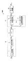
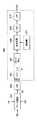
図1を参照して、本発明の第1実施形態に係るOFDM復調装置について説明する。本実施形態に係るOFDM復調装置DMPは、サブキャリア分離部10と位相補正器11とデータ復調器13とを備えている。サブキャリア分離部10は、A/D変換器1、直交検波器3、および高速フーリエ変換器5を有し、位相補正器11は、データキャリア位相誤差推定器7およびデータキャリア位相補正器9を有している。
【0079】
A/D変換器1、直交検波器3、および高速フーリエ変換器5は、図14に示した従来のOFDM復調装置DMCにおけるA/D変換器101、直交検波器103、および高速フーリエ変換器105のそれぞれと基本的に同様の構成である。A/D変換器1は入力されたOFDM信号So’をアナログ/デジタル変換してOFDM信号So”を生成し、直交検波器3はOFDM信号So”を直交検波してベースバンド帯域のOFDM信号Sb’を生成し、そして高速フーリエ変換器5はベースバンド帯域のOFDM信号Sb’に高速フーリエ変換処理を施してサブキャリア信号Sc’を生成する。
【0080】
しかしながら、本実施形態のOFDM復調装置DMPには、従来のOFDM復調装置DMCに於けるクロック同期確立器102、周波数同期確立器104、およびシンボル同期確立器106に相当する手段が設けられていない。その結果、生成されたこれらの信号So”、Sb’、およびSc’は、サンプリングクロック、サブキャリア信号の周波数、およびシンボル窓について同期確立されていない。
【0081】
このように同期が取れていないサブキャリア信号Sc’は、データキャリア位相誤差推定器7およびデータキャリア位相補正器9に出力される。データキャリア位相誤差推定器7は、OFDM復調されたサブキャリアSc’中のパイロットキャリアPCに基づいて受信OFDM信号So’中のデータキャリアDCの位相誤差を推定し、推定された位相誤差の補正量SHCを表す位相誤差補正信号Shcを生成してデータキャリア位相補正器9に出力する。
【0082】
データキャリア位相補正器9は、この位相誤差補正信号Shcに基づいて、サブキャリア信号Sc’中のデータキャリアDCを直接補正することでクロックずれ、周波数ずれ、およびシンボルずれ(FFT時間窓ずれ)による影響(位相回転)を補正して位相補正サブキャリア信号Scrとして、データ復調器13に出力する。データキャリア位相誤差推定器7とデータキャリア位相補正器9とは、OFDM信号の位相を補正する位相補正器11を構成している。
【0083】
なお、データキャリア位相誤差推定器7による位相誤差補正量を求める方法は、サブキャリアSCの位相変調方式により異なる。例えば、QPSKやQAM変調のようにサブキャリアが絶対位相変調されている場合には各サブキャリアの絶対位相誤差(送受信間の位相誤差)を求める。また、DQPSKやDAPSK変調のようにサブキャリア間で差動変調されている場合はサブキャリア間の相対位相誤差を求める。但し、サブキャリア間が差動変調されている場合にも、絶対位相誤差を求めることによって位相誤差補正量を求めることができる。位相補正器11の具体的な構成について、図4、図6、および図8を参照して以下に詳しく説明する。
【0084】
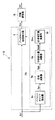
(第1実施例)
図4を参照して、本発明の第1実施例に係る位相補正器11について述べる。本実施例では、サブキャリアSCが絶対位相変調されているOFDM信号の復調に特に適している。絶対位相変調されているサブキャリアSCの位相を補正する位相補正器11Aは、サブキャリアSCの絶対位相誤差を求めるデータキャリア位相誤差推定器7Aとデータキャリア位相補正器9から構成される。さらに、データキャリア位相誤差推定器7Aは、パイロットキャリア位置検出器8a、パイロットキャリア抽出器8b、パイロットキャリアメモリ8c、位相差演算器8d、位相変化量演算器8e、および位相補正量演算器8fより成る。パイロットキャリア位置検出器8aには、送信側で何番のサブキャリアがパイロットキャリアに割り当てられているかの情報が保存されている。パイロットキャリアメモリ8cには、送信側で既知の複素数を割り当てた送信パイロットキャリアPCの情報SPCが予め保持されている。
【0085】
FFT回路5で周波数領域の信号Sfに変換された受信データSc’には、図2に示したように同一時間上に各サブキャリアSCが分離されて、その周波数順に配列されている。このように分離配列されたの複数個のサブキャリアを示す複素数データが得られる。これら複数の分離されたサブキャリアSCのそれぞれはパラレルにデータキャリア位相誤差推定器7Aのパイロットキャリア位置検出器8aおよびパイロットキャリア抽出器8bの双方に入力される。
【0086】
パイロットキャリア位置検出器8aは、送信側で割り当てられた順番に基づいて、サブキャリアSc’中のパイロットキャリアPCの位置を検出してパイロットキャリア位置信号Lpcを生成してパイロットキャリア抽出器8bおよびパイロットキャリアメモリ8cに出力する。しかしながら、この送信側でサブキャリアに割り当てられた順番に基づいてパイロットキャリアの位置を検出する方法は、OFDM信号の周波数オフセットがキャリア間隔以上になるとFFT回路5の出力であるサブキャリアSC中のデータキャリアの位置がずれるため、パイロットキャリアPCの位置を正しく検出することができない。このような場合には、送信側でパイロットキャリアPCとデータキャリアDCとを異なるパワーレベルで変調しておき、その変調パワーレベルに基づいてパイロットキャリアPCの位置を検出するようにしても良い。
【0087】
パイロットキャリア抽出器8bは、入力されたサブキャリアSc’中のパイロットキャリアPCを抽出する。すなわち、パイロットキャリア抽出器8bは、パイロットキャリア位置信号Lpcに基づき、パイロットキャリア位置検出器8aで検出されたパイロットキャリアPCの位置に相当するサブキャリアSCを抽出して、受信パイロットキャリア信号Rpcを生成すると共に、位相差演算器8gに出力する。
【0088】
パイロットキャリアメモリ8cは、パイロットキャリア位置信号Lpcに基づいて、検出されたパイロットキャリアPCの位置に対応するパイロットキャリアPCの情報SPC(すなわちパイロットキャリアPCに割り当てられた既知複素数)を自身から読み出して、送信パイロットキャリア信号Spcとして位相差演算器8dに出力する。
【0089】
位相差演算器8dは、受信パイロットキャリア信号Rpcと送信パイロットキャリア信号Spcに基づいて、パイロットキャリア抽出回路8bで抽出された受信パイロットキャリアPC(R)と、パイロットキャリアメモリ8cに保持されている送信パイロットキャリアPC(S)を比較し、その位相差PDを求める。位相差PDは、受信パイロットキャリアに割り当てられた複素数Aと、送信パイロットキャリアに割り当てられた複素数Bを入力とし、複素数Aと複素数Bの共役複素数とを乗算し、得られた複素数C=(i,q)から逆正接arctan(q/i) を演算して求めることができる。
【0090】
位相差PDは、また、複素数Aと複素数Bの位相を、それぞれ逆正接arctan演算で求め、それらを引き算することで求めることもできる。このようにして求められた位相差PDは、各キャリアが送信時の位相から受信側の周波数ずれおよび時間ずれによってどれだけ位相回転したかを表わす。位相差演算器8dは更に、位相差PDを示す送受信間位相差信号Spdを生成して、位相変化量演算器8eおよび位相補正量演算器8fの双方に出力する。
【0091】
位相変化量演算器8eは、送受信間位相差信号Spdに基づいて、各パイロットキャリアの送受信間位相差PDとキャリア周波数から、キャリア周波数に対する送受信間の位相差変化量APDを求める。位相変化量APDは、各パイロットキャリア間の位相変化を補間することで求めることができる。なお、キャリア周波数は各パイロットキャリアの周波数であるので、各パイロットキャリアの位置を知ることにより求めることができる。
【0092】
例えば、各パイロットキャリアの送受信間位相差PDを縦軸に、キャリア周波数を横軸にとり、直線近似することでこの直線の傾きを求め、この傾きから位相変化量を求めることができる。また、任意のパイロットキャリア間の送受信間位相差の差をそのパイロットキャリアPC間のキャリア周波数差で割ることで、2つのパイロットキャリア間の位相変化量を求めることもできる。さらにそれをシンボル内の各パイロットキャリアPCで順に計算し、その平均値を求めることでより高精度に位相変化量を求めることができる。つまり、任意の二つのパイロットキャリアPCをPCaとPCbとし、パイロットキャリアPCaの送受信間位相差φaとパイロットキャリアPCbの送受信間位相差φbとの差φa−φbをPCaとPCbの周波数差Fa−Fbで割ると、パイロットキャリアPCaとPCbの間における、キャリア周波数に対する位相変化量△φが求まる。すなわち、次式により位相変化量Δφが求まる。
△φ=(φa−φb)/(Fa−Fb)
【0093】
更に詳述すれば、各サブキャリアの位相誤差φ(k)を全て元に戻す必要があるので、各サブキャリアの補正量φ’(k)は、先頭のキャリアの位相誤差φ(k)に△φを累積していけば良い。それ故、補正量は、φ’(k)=−(k△φ+φ(0))で表すことができる。
【0094】
図5を参照して、以下に、周波数ずれΦfおよび時間ずれΦtによる位相回転について説明する。同図において、Θ(PCn)はn番目のパイロットキャリアPCの送受信間位相差PDを、ΔΦはキャリア間の位相誤差を、kはデータキャリアDCの番号を表す。nとkは正の整数である。各データキャリアDCは、Θ(PCn )を基準にΔΦが累算された分だけ位相回転を起こしている。よって、各データキャリアの位相補正量SHCはパイロットキャリアPCの送受信間位相差Θ(PCn )を基準に、位相変化量演算器8eで求めた位相誤差ΔΦに相当する位相変化量APDを累算することで求められる。これにより、各データキャリアDCが周波数ずれΦfおよび時間ずれΦtにより送信時の位相から回転した位相回転量を求めることができる。
【0095】
位相変化量演算器8eは、このようにして求めた位相変化量APDを示す送受信間位相差変化量信号Sapdを生成して位相補正量演算器8fに出力する。
【0096】
位相補正量演算器8fは、送受信間位相差信号Spdおよび送受信間位相差変化量信号Sapdに基づいて、各パイロットキャリアの送受信間位相差PDとキャリア周波数に対する位相変化量APDとから、各データキャリア毎の位相補正量SHCを求めて位相誤差補正信号Shcを生成する。各データキャリア毎の位相補正量SHCを求めるには、連続する二つのパイロットキャリアPC1およびPC2が入力された時点で、その二つのパイロットキャリアPC1およびPC2間のデータキャリアDCの補正量を算出する方法と、1シンボル内のすべてのパイロットキャリアPCが入力された時点で1シンボル内のすべてのデータキャリアDCを一括してデータキャリアDCの補正量を求める方法との二通りの方法がある。
【0097】
データキャリア位相補正器9は、位相誤差補正信号Shcに基づいて、各データキャリア毎の位相補正量SHCに基づき、各データキャリアの位相を位相補正量分だけ戻すことで位相補正を行う。上述のように、位相補正量演算器8fが複数のパイロットキャリアPCに基づいて位相補正量SHCを演算し終わる迄の間、少なくともその複数のパイロットキャリアPC間に位置するデータキャリアDCの位相補正はできないので、その間それらのデータキャリアDCを保持しておく必要がある。このデータキャリアDCの保持のためには、適当な容量のバッファをデータキャリア位相補正器9に設けるか、或いは高速フーリエ変換器5中に設けられているフーリエ演算時に必要とされるバッファを読み出しタイミングを適切に制御することで共用できる。位相補正された各データキャリアScrは、データ復調器13で復調されて、送信データSd’が再生される。
【0098】
第1実施例においては、データキャリアDCの変調にはどのような方式を用いても良く、例えばQPSKや16QAM、またDQPSKや16DAPSKなどの差動変調方式を用いてもよい。これらの演算は例えばDSPなどを用いることで実現することができる。さらにFFT以降の処理ステップはプログラムとして記録媒体に記録して実行することで処理することもできる。
【0099】
(第2実施例)
図6を参照して、本発明の第2実施例に係る位相補正器11について述べる。本実施例に於ける位相補正器11Bは、第1実施例に係る位相補正器11Aと異なり、OFDM変調装置の上記第2の実施形態によって得られるOFDM信号のようにサブキャリアSCが差動変調されているOFDM信号の復調に特に適している。データキャリアDCを周波数方向に隣接するサブキャリア間で差動変調している場合、周波数ずれによる一定の位相回転は差動復調によりキャンセルされるが、隣接キャリアの位相差に時間ずれによる位相誤差が加えられ、正しく差動復調することができない。
【0100】
図7に、差動変調によるOFDM信号の様子を示す。kはサブキャリアSCの番号を表す。送信側ではサブキャリアkとサブキャリアk+1の位相差Θに送信データを割り当てる。時間ずれが生じた場合、各サブキャリア周波数に比例して位相誤差が生じる。そのため、サブキャリアk+1はサブキャリアkに対し、本来の位相差から更に位相誤差ΔΦだけ回転した(k+1)’となる。
【0101】
サブキャリア(k+1)’とサブキャリアkの位相差はΘ+ΔΦとなり、この隣接サブキャリアで差動復調を行っても、正しく送信データを再生することができなくなる。そこで、本実施例は、隣接サブキャリア間の位相誤差のみを求め、位相補正を行うために、以下に述べるように構成される。本実施例に係るOFDM復調器は、位相補正器11Aが位相補正器11Bに変わると共に、データ復調器13が差動復調器15と交換された構造を有している。
【0102】
位相補正器11Bは位相補正器11Aのデータキャリア位相誤差推定器7Aがデータキャリア位相誤差推定器7Bに交換された構成を有している。データキャリア位相誤差推定器7Bは、データキャリア位相誤差推定器7Aのパイロットキャリア位置検出器8aおよびパイロットキャリアメモリ8cが取り除かれ、位相差演算器8dが位相演算器8gに交換されると共に、位相補正量演算器8fに対する位相差演算器8dの出力を取りやめた構成を有している。
【0103】
FFT回路5で周波数領域に変換し各サブキャリアに分離した受信データSc’は、データキャリア位相誤差推定器7Bのパイロットキャリア抽出器8bに入力される。
【0104】
パイロットキャリア抽出器8bは、サブキャリアSc’中のパイロットキャリアPCを抽出して、受信パイロットキャリア信号Rpc’を生成すると共に、位相演算器8gに出力する。
【0105】
位相演算器8gは、受信パイロットキャリア信号Rpc’に基づいて、パイロットキャリア抽出器8bで抽出された受信パイロットキャリアPC(R)の位相を求める。位相演算は、入力される受信パイロットキャリアPC(R)に割り当てられた複素数(i,q)から逆正接arctan(q/i) を演算することで受信パイロットキャリアPC(R)の位相PHを求めることができる。また、複素数(i,q)からq/iを演算することにより受信パイロットキャリアPC(R)の位相の近似値を求めるようにしてもよい。
【0106】
本実施例においては、OFDM信号に含まれるサブキャリアは周波数方向に隣接するサブキャリア間で差動変調されているため、サブキャリア間の位相誤差がどれだけあるかを求めれば良く、各サブキャリアが送信時の位相からどれだけ回転したかは考慮しなくて良い。また、このように差動変調されていることに加えて、送信パイロットキャリアのそれぞれの位相は同一であるため、第1実施例のデータキャリア位相誤差推定器7A(位相差演算器8d)のように、受信パイロットキャリアと送信パイロットキャリアとの間で位相を比較して送受信間位相差を求める必要はない。このようにして、受信パイロットキャリアの位相PHを検出した後に、位相演算器8gは受信パイロットキャリア位相信号Sphを生成して位相変化量演算器8eに出力する。
【0107】
位相変化量演算器8eは、受信パイロットキャリア位相信号Sphに基づいて、位相演算器8gで求めた受信パイロットキャリアPC(R)の位相PHとキャリア周波数から、第1実施例と同様に直線近似等の方法を用いてキャリア周波数に対する送受信間の位相変化量APD’を求める。そして、求めた位相変化量APD’を示す送受信間位相差変化量信号Sapd’を位相補正量演算器8fに出力する。
【0108】
位相補正量演算器8fは、送受信間位相差変化量信号Sapd’に基づいて、キャリア間の位相補正量HCを求める。本実施例においては、データキャリアDCは隣接キャリア間で差動変調されているため、隣接キャリア間での時間ずれによる位相回転量だけを補正すればよい。この場合、位相補正量演算器8fは、比較するキャリア間のキャリア周波数に対する位相誤差を補正する位相補正量を演算する。例えば、隣接キャリア間で比較する場合、1キャリア周波数間隔分の位相誤差を求めるので、位相変化量演算器8eで求めたキャリア周波数に対する位相変化量APD’が位相誤差ΔΦに相当する。2キャリア周波数間隔分離れたキャリアを比較して、2ΔΦを演算することで位相補正量が求まる。
【0109】
更に詳述すると、差動変調ではサブキャリアSC間の位相差に情報を乗せているので、データに割り当てられた位相差はθk+1−θk=θd( θkはk番目のサブキャリアの位相)で表される。OFDM信号が受信側で受信された後に、サブキャリアSCに同じ位相誤差が発生しても、位相差は変わらない。ところが、サブキャリア周波数(k)に比例する位相誤差k△φがあると、θk'+1−θk'=θd+△φとなる。よって、補正量として△φを求めれば良い。
【0110】
データキャリア位相補正器9は、位相補正量演算器8fで求めた位相補正量HCに基づき、高速フーリエ変換器5が出力する各データキャリアSc’の位相を補正する。位相補正は、差動復調を行う2つのデータキャリアに対して、そのデータキャリア間に対する位相補正量分だけ位相を戻すことで行う。
【0111】
差動復調器15は、データキャリア位相補正器9から出力された位相補正サブキャリア信号Scrを差動復調して送信データSd’を再生する。
【0112】
本実施例において、データキャリアの変調には、隣接キャリア間での差動変調方式を用い、例えばDQPSKなどの多値差動位相変調や16DAPSKなどの多値差動振幅位相変調方式を用いることができる。このように、隣接データキャリアを差動変調しておくことで、受信側における位相補正量の演算は簡単になり、第1実施例に比べ構成を簡単にできる。本実施例においては、サブキャリア自体の位相補正、つまり時間ずれの位相誤差を補正する。そして、補正されたサブキャリア間の位相差を求めることによって、周波数ずれの位相誤差をキャンセルすると共に求められた位相差をデマッピングしてデータを復調する。
【0113】
これらの演算は第1実施例同様、DSPなどを用いて実現することができる。さらにFFT以降の処理ステップはプログラムとして記録媒体に記録して実行することで処理することもできる。
【0114】
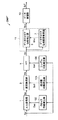
(第3実施例)
図8を参照して、本発明の第3実施例に係る位相補正器11について述べる。本実施例に於ける位相補正器11Cは、第2実施例に係る位相補正器11Bと同様に、サブキャリアSCに対し周波数方向に隣接するサブキャリア間での差動変調が行われているOFDM信号の復調に特に適している。位相補正器11Cは、第2実施例に係る位相補正器11Bのデータキャリア位相補正器9と高速フーリエ変換器5との間にキャリア間位相差演算器6を挿入すると共に、差動復調器15をデータ復調器13に戻した構成である。よって、データキャリア位相誤差推定器7Bの構成および動作については説明済みであるので、キャリア間位相差演算器6に関してのみ説明する。
【0115】
キャリア間位相差演算器6は、高速フーリエ変換器5からの出力であるサブキャリアSc’から、送信データに相当する隣接サブキャリア間の位相差を演算し、演算結果を位相差信号Sc”として、データキャリア位相補正器9に出力する。位相差信号Sc”において、周波数ずれによる位相誤差は既にキャンセルされているが時間ずれによる位相誤差は含まれたままである。
【0116】
データキャリア位相補正器9は、位相誤差補正信号Shcに基づいて、位相差信号Sc”の位相補正を行った後、位相補正サブキャリア信号Scrをデータ復調器13に出力する。
【0117】
本実施例においても、第2実施例と同様にデータキャリアの変調方式は周波数方向の隣接キャリア間での差動変調を用い、例えばDQPSKなどの多値差動位相変調や16DAPSKなどの多値差動振幅位相変調などを用いることができる。さらに、これらの演算は第1実施例同様DSPなどを用いて実現することができる。さらにFFT以降の処理ステップはプログラムとして記録媒体に記録して実行することで処理することもできる。このように、本実施例においては、キャリア間位相差演算によってサブキャリア間の位相差を求めるときに、周波数ずれの位相誤差がキャンセルされる。その後に、求められたサブキャリア間の位相差を補正することによって時間ずれの位相誤差を補正する。そして、補正された位相差をデマッピングしてデータを復調する。
【0118】
以上に述べたように、本発明の第1実施形態に係るOFDM復調装置DMPは、OFDMシンボル内に埋め込まれた既知の位相を有するパイロットキャリアPCに基づいて位相補正を行うために、図13に示すOFDM信号のように同期シンボルRSがフレームに挿入されていなくても、正確な復調が可能である。
【0119】
(第2の実施形態)
図9を参照して本発明の第2実施例に係るOFDM復調装置について以下に説明する。本実施形態にかかるOFDM復調装置DMP’は、同期シンボルRSとフレームで構成されて送信される従来のOFDM信号の復調に適している。本実施形態で用いられるOFDM信号は、図13に示すフレームを構成する各シンボル内に、図2および図3に示したパイロットキャリアPCを埋め込んだ構造を有する。OFDM信号をこのように構成することによって、同期基準シンボルRSに基づいて、図14に示した各同期確立器によってある程度同期をとり、同期確立器で追い込めないずれに関しては、図1に示す位相補正器11によって位相補償をして、さらに復調の精度を上げるようにしたものである。
【0120】
つまり、本実施形態に係るOFDM復調装置DMP’は、図1に示すOFDM復調装置DMPに、図14に示したクロック同期確立器102、周波数同期確立器104、およびシンボル同期確立器106が追加された構造を有する。その結果、上述のように、高速フーリエ変換器5は、シンボル時間窓信号Sstに基づいて、ベースバンド帯域のOFDM信号Sbに高速フーリエ変換処理を施す。そして、ベースバンド帯域の信号Sbを個々のOFDMシンボルOS毎に、時間領域の信号を周波数領域の各サブキャリアSCに分離してシンボル同期の確立したサブキャリア信号Scを生成して位相補正器11に出力する。このサブキャリア信号Scは、シンボル窓の同期確立に併せて、サンプリングクロック同期およびキャリア信号の周波数同期が確立されている。
【0121】
以降、この同期が確立されたサブキャリア信号Scに対して、第1実施形態に関して説明した種々の位相補正器11、11A、11B、および11Cのいずれかによって位相補正を施して、より精度の高い復調を可能にするものである。
【0122】
なお、本実施形態において、アナログのOFDM信号So’に対してA/D変換を行う際、受信側サンプリングクロックと送信側のサンプリングクロックとの間にずれがある場合について説明する。OFDM復調は一つのOFDMシンボル期間毎にFFT演算を施すことにより、時間領域の信号を周波数領域の信号に変換して、各サブキャリアに分離する。FFT回路には、FFTに用いるポイント数だけのデータ(信号値)を1つのOFDMシンボルから取り出して入力する。これを有効シンボル期間という。FFTに用いるポイント数は、例えば1024または512などである。送受信間でサンプリングクロックずれが生じた場合、同じポイント数(例えば1024)だけデータを取り込んだとしても、時間ずれが生じる。
【0123】
図10に、このような送受信間での時間ずれを生じた様子を示す。OSrは、受信したOFDMシンボルの一つを示す。受信OFDMシンボルからガードインターバルを取り除き、FFTに用いる1024ポイント分のデータ、すなわち有効シンボル期間を取り出す。OSesは、送信側でこのシンボルを発生した時の有効シンボル期間を示している。送受信間でサンプリングクロックにずれが生じた場合、受信側で取り込む有効シンボル期間はOSerに示すようになり、本来の有効シンボル期間と時間ずれが生じる。
【0124】
このようにして取り込んだ有効シンボル期間に対しFFT演算を施すと、有効シンボル期間の時間ずれにより各サブキャリアに位相回転が生じる。この様子を図5に示す。有効シンボル期間の時間ずれによる位相回転量はサブキャリア周波数に比例する。また、送受信間で周波数ずれがある場合に直交検波を行うと、各サブキャリアはサブキャリア周波数に依らず一定値だけ位相回転を起こす。
【0125】
よって、各受信サブキャリアは周波数ずれによる一定の位相回転とキャリア周波数に比例する位相回転を起こす。OFDM信号のサブキャリアは一定周波数間隔で配置されるため、隣接サブキャリア間の位相回転量は一定値となる。図11はこれを示している。kはサブキャリア番号を表す。
【0126】
時間ずれによる位相回転量は周波数に比例するため、この直線の傾きから隣接キャリア間の位相変化量が求まり、これが隣接キャリア間の位相誤差ΔΦに相当する。よって、受信側で周波数ずれによる一定の位相回転と時間ずれによるキャリア周波数に比例する位相回転を求め、データキャリアの位相を補正することで正しくデータを復調できる。そこで本実施形態においては、OFDM復調し各サブキャリアに分離した受信信号を、上述の如く位相補正を行った後にデータ復調を行う。
【0127】
以上詳述したように本発明によれば、送信側と受信側との間に周波数ずれおよび時間ずれがある場合でも、データを正しく復調することができる。またバースト状に送信されるOFDM信号には、安定したクロック同期が非常に困難であるが、本発明では、OFDMシンボル毎に周波数ずれ、時間ずれによる位相誤差の補正が可能なので、そのようなバースト状のOFDM信号であってもデータを正しく復調することができる。
【図面の簡単な説明】
【図1】本発明の第1実施形態に係るOFDM復調装置を示すブロック図。
【図2】本発明に係るOFDM信号およびその変調と復調の基本概念についての説明図。
【図3】図2に示したOFDM周波数軸信号に於けるサブキャリアの詳細な構成についての説明図。
【図4】本発明の第1実施形態に係るOFDM復調装置の第1実施例を示すブロック図。
【図5】周波数ずれ、および時間ずれによる位相回転についての説明図。
【図6】本発明の第1実施形態に係るOFDM復調装置の第2実施例を示すブロック図。
【図7】差動変調によるOFDM信号の様子を示す説明図。
【図8】本発明の第1実施形態に係るOFDM復調装置の第3実施例を示すブロック図。
【図9】本発明の第2実施形態に係るOFDM復調装置を示すブロック図。
【図10】送受信間での時間ずれを生じたOFDM信号の様子を示す説明図。
【図11】OFDM信号に於ける時間ずれによる隣接キャリア間の位相回転の説明図。
【図12】従来例のOFDM伝送フレームの説明図。
【図13】従来のOFDM信号の周波数領域および時間領域での状態の説明図。
【図14】従来のOFDM復調装置を示すブロック図。
【図15】OFDM信号を用いた伝送システムを示す図。
【図16】本発明に係るOFDM変調装置の第1の実施形態の構成を示すブロック図。
【図17】本発明に係るOFDM変調装置の第2の実施形態の構成を示すブロック図。
【図18】本発明に係るOFDM変調装置の第2の実施形態における差動変調を説明するための図。
【符号の説明】
DMP、DMP’…OFDM復調装置
1 …A/D変換器
3 …直交検波器
5 …FFT回路
6 …キャリア間位相差演算器
7 …データキャリア位相誤差推定器
8a …パイロットキャリア位置検出器
8b …パイロットキャリア抽出器
8c …パイロットキャリアメモリ
8d …位相差演算器
8e …位相変化量演算器
8f …位相補正量演算器
8g …位相演算器
9 …データキャリア位相補正器
10 …サブキャリア分離部
11 …位相補正器
13 …データ復調器
15 …差動復調器
120…送信装置
121…OFDM変調装置
130…伝送路
140…受信装置
141…OFDM復調装置
200…OFDM信号生成部
201…データ変調部
231…差動変調部[0001]
BACKGROUND OF THE INVENTION
The present invention relates to a modulation device and a demodulation device used for orthogonal frequency division multiplexing (hereinafter referred to as “OFDM”) transmission, and more particularly to a phase correction technique.
[0002]
[Prior art]
In recent years, transmission schemes using OFDM technology have attracted attention in digital audio broadcasting for mobiles and terrestrial digital television broadcasting. This OFDM technology is a type of multi-carrier modulation, in which data to be transmitted (transmission data) is assigned to a number of subcarriers that are orthogonal to each other between adjacent neighbors, and further converted to a time-domain digital modulation signal by inverse Fourier transform. To generate an OFDM signal. In OFDM transmission, an OFDM signal generated by performing the above-described processing on transmission data on the transmission side is transmitted to the reception side. On the receiving side, the transmitted data is reproduced by performing a process opposite to the process performed on the transmitting side on the transmitted OFDM signal. The OFDM signal has a characteristic that it is difficult to be affected by delay waves such as multipath because the period of each data divided into subcarriers becomes long.
[0003]
OFDM demodulation is quadrature detectionvesselIs performed by subjecting the OFDM signal down-converted to the baseband band by a Fourier transform process using a fast Fourier transform (hereinafter referred to as “FFT”) circuit. At this time, quadrature detectionvesselIn the FFT, it is necessary to establish accurate frequency synchronization between transmission and reception. In the FFT, one symbol period is accurately captured from the received OFDM signal with a prescribed clock, and Fourier transform is performed to obtain the phase and amplitude information of each subcarrier. Need to get.
[0004]
When there is a frequency shift and a time shift that cannot accurately capture one symbol period with respect to the OFDM signal in each transmission / reception, each subcarrier causes phase rotation and transmission data cannot be reproduced. As described above, accurate frequency synchronization, symbol synchronization, and clock synchronization are required for OFDM demodulation, and in the conventional OFDM demodulator, it is necessary to establish each of frequency synchronization, symbol synchronization, and clock synchronization using a synchronization symbol. There is. For this reason, as shown in FIG. 11, the OFDM signal So is composed of a plurality of OFDM symbols OS each composed of a plurality of (..., k, k + 1, k + 2,...) Subcarriers SC. A synchronization symbol is inserted for each frame and transmitted. In the figure, the vertical axis represents the phase φ, and the horizontal axis represents the subcarrier frequency F. Δφ indicates a phase error between adjacent subcarriers.
[0005]
Furthermore, as shown in FIG. 12, one transmission frame Fr is configured by inserting a null symbol as a synchronization symbol RS at the head of n (n is an integer of 1 or more) OFDM symbols OS. Synchronization is established by detecting symbols continuously. Note that the null symbol does not have to be OFDM-modulated, and a signal from which synchronization information can be easily obtained can be used. That is, since the OFDM signal So has a random noise waveform, it is difficult to obtain the synchronization information directly from the time axis waveform. Therefore, a sinusoidal waveform signal can be used for frequency synchronization, and a waveform signal modulated by an amplitude shift keying (ASK) system that can easily extract a clock component can be used for clock synchronization.
[0006]
With reference to FIG. 13, the concept of the OFDM signal configured as described above will be described. The state SF in the frequency domain of the OFDM signal is schematically shown in the left half of the figure, and the state ST in the time domain is schematically shown in the right half of the figure. The frequency axis signal SF is configured by arranging each of the OFDM symbols OS1 to OSn so that a large number of subcarriers SC are orthogonally crossed on the frequency axis F. The time axis signal ST is generated by subjecting the frequency axis signal SF to inverse Fourier transform and OFDM modulation. Each subcarrier SC is arranged with a subcarrier at an interval P = 1 / PS (Hz) subjected to primary modulation on the transmission side, and is converted into a signal ST on the time axis T in the symbol period PS (sec) by inverse Fourier transform. The
[0007]
In the case of transmission from the transmission side, the OFDM symbol OS and the synchronization reference symbol RS constitute an OFDM signal transmission frame for transmission. The synchronization reference symbol RS does not need to be an OFDM modulated symbol, and may be a signal having a waveform that is easy to use for synchronization processing.
[0008]
On the receiving side, only the synchronization reference symbol RS is extracted from the input signal ST on the time axis, and synchronization control is performed. The OFDM symbol OS is cut out every symbol period PS, and further subjected to Fourier transform to be converted into a signal SF on the frequency axis, whereby the OFDM symbol OS is separated into subcarriers SC. Thereafter, primary demodulation (data demodulation) is performed on each separated subcarrier SC, whereby reception data is obtained, that is, transmission data is reproduced. In order to maintain accurate synchronization in such demodulation processing of the OFDM signal, it is necessary to periodically transmit a synchronization reference symbol.
[0009]
The OFDM demodulator disclosed in Japanese Patent Laid-Open No. 8-102769 will be described below as an example of such a conventional OFDM demodulator with reference to FIG. The OFDM demodulator DMC includes an A /
[0010]
Based on the synchronization symbol RS in the OFDM signal So ′, the clock synchronization establisher 102 detects a sampling clock synchronization shift between transmission and reception of the OFDM signal. The
[0011]
Based on the synchronization symbol RS in the OFDM signal So ′, the frequency synchronization establisher 104 detects a frequency synchronization shift of the carrier signal between transmission and reception, generates a synchronized frequency signal Scf, and performs quadrature detection. Output to the
[0012]
Based on the synchronization symbol RS in the OFDM signal So ′, the symbol synchronization establisher 106 detects a symbol time window synchronization shift between transmission and reception, generates a symbol time window signal Sst in which synchronization is established, and generates the same signal Sst. Is output to the fast Fourier
[0013]
The
[0014]
The conventional OFDM demodulator DMC uses quadrature detection.vesselThe fast Fourier transform (FFT)
[0015]
[Problems to be solved by the invention]
On the OFDM demodulator side, regarding the sampling clock, carrier frequency, and FFT symbol window time, it is necessary to accurately reproduce the same conditions as those on the transmission side to perform data processing. That is, at the time of OFDM demodulation, synchronization of the sampling clock, carrier frequency, and symbol time window must be established. On the other hand, a conventional OFDM demodulator detects symbol for synchronization inserted intermittently at a predetermined interval to establish symbol synchronization and clock synchronization. In this case, it is necessary to detect synchronization symbols for several frames before synchronization is established, and the OFDM symbols during that period cannot be accurately demodulated. However, a synchronization shift between transmission and reception is easily caused by a change in transmission environment, for example, and causes a clock shift, a frequency shift, and a time window shift. When these deviations occur, each carrier of the symbol subjected to OFDM modulation undergoes phase rotation by an amount corresponding to these deviations from the phase at the time of transmission. Since information (transmission data) is assigned to the phase of each subcarrier, the transmission data is erroneously reproduced.
[0016]
For these deviations, the information is detected from the reference symbol for synchronization, and the sampling clock deviation, carrier frequency deviation, and symbol time window deviation are fed back as respective error signals and adjusted (established) one by one. Synchronized. Therefore, a phase rotation error occurs in the subcarrier of the OFDM symbol demodulated at the time when these deviations occur, and transmission data is erroneously reproduced. Furthermore, if synchronization symbols cannot be detected continuously at a predetermined interval, stable synchronization cannot be established, and it is very difficult to accurately demodulate OFDM symbols transmitted in bursts.
[0017]
Therefore, the present invention has been made to solve the above problem, and corrects the phase error of each subcarrier and demodulates the OFDM symbol even when there is a frequency shift or time shift between transmission and reception. It is an object of the present invention to provide a modulation device and a demodulation device for OFDM transmission.
[0018]
[Means for Solving the Problems and Effects of the Invention]
In order to achieve the above object, the present invention has the following features.
[0019]
The first invention provides a plurality of subcarriers including a plurality of data carriers and a plurality of pilot carriers.Composed ofMultiple OFDM symbolsGenerated fromAn OFDM demodulator for receiving an OFDM signal,
Subcarrier separation means for separating the received OFDM signal into the plurality of subcarriers by Fourier transform for each OFDM symbol, and obtaining the phase and amplitude of each subcarrier;
Pilot carrier position detecting means for detecting positions of the plurality of pilot carriers from the plurality of subcarriers;
Each of the plurality of pilot carriers is assigned a known phase and amplitude, and a phase difference between transmission and reception for each pilot carrier is determined by the phase obtained from the received OFDM signal in each pilot carrier and the known phase. By finding the differencePhase difference detection means for detecting;
Based on the phase difference of the pilot carrier, the amount of change in the phase difference of the transmission / reception that occurs between adjacent subcarriers due to the phase rotation that occurs due to the time lag between transmission and receptionA phase change amount calculating means for calculating;
A phase correction amount calculating means for calculating a phase correction amount for each of the plurality of data carriers based on the change amount;
The phasecorrectionBased on quantityObtained from the received OFDM signal for each data carrierPhase correction means for correcting the phase.
[0020]
According to the first invention as described above,Because the phase difference between the transmission and reception of the pilot carrier is detected, the amount of change in the phase rotation amount between transmission and reception with respect to the carrier frequency is calculated based on this phase difference, and the amount of phase correction for each subcarrier is calculated based on this amount of change This phase correction amount corresponds to the absolute phase error (phase error between transmission and reception) of each subcarrier. Therefore, even for an OFDM signal in which absolute phase modulation such as QPSK or QAM modulation is performed on the subcarrier, the phase error of each subcarrier can be corrected and demodulated correctly.
[0021]
According to a second invention, in the first invention,
The phase change amount calculation means calculates the difference between the phase difference in the first pilot carrier and the phase difference in the second pilot carrier that is continuous with the first pilot carrier, and calculates the difference between the first pilot carrier and the second pilot. The amount of change is calculated by dividing by the difference in carrier frequency.
[0022]
According to a third invention, in the second invention,
The phase change amount calculation means calculates the difference between the phase difference in the first pilot carrier and the phase difference in the second pilot carrier that is continuous with the first pilot carrier, and calculates the difference between the first pilot carrier and the second pilot. The amount of change is calculated by dividing by the difference in carrier frequency.
[0023]
According to a fourth invention, in the first invention,
The phase change amount calculating means includes a phase difference and a frequency of a first pilot carrier arranged on a two-dimensional plane having a phase difference on the vertical axis and a frequency on the horizontal axis, and a second phase that is continuous with the first pilot carrier. The phase difference and frequency of the pilot carrier are linearly approximated, and the amount of change is calculated from the slope of the straight line.
[0024]
According to a fifth invention, in the first invention,
The phase change amount calculation means performs an operation for dividing a phase difference difference between a set of pilot carriers by a frequency difference between the set of pilot carriers for a plurality of sets of pilot carriers, and calculates the result of the calculation. The amount of change is calculated by averaging.
First6In the first invention,
The OFDM demodulator comprises:
Data demodulation means for demodulating the phase-corrected data carrier is further provided.
[0025]
First7In the first invention,
The OFDM signal is input in bursts.
[0026]
First8The invention of
An OFDM demodulation method for receiving and demodulating an OFDM signal generated from a plurality of OFDM symbols composed of a plurality of subcarriers including a plurality of data carriers and a plurality of pilot carriers,
Separating the received OFDM signal into the plurality of subcarriers by Fourier transform for each OFDM symbol, and determining the phase and amplitude of each subcarrier;
Detecting positions of the plurality of pilot carriers from the plurality of subcarriers;
Each of the plurality of pilot carriers is assigned a known phase and amplitude, and the phase difference between transmission and reception for each pilot carrier is determined by the difference between the phase obtained from the received OFDM signal in each pilot carrier and the known phase. Detecting by determining
Calculating a change amount of a transmission / reception phase difference between adjacent subcarriers based on a phase difference caused by a time lag between transmission and reception and caused by phase rotation proportional to the frequency, based on the phase difference of the pilot carrier;
For the plurality of data carriers, calculating a phase correction amount for each data carrier based on the amount of change;
Correcting the phase obtained from the received OFDM signal for each data carrier based on the phase correction amount.
[0027]
First9The invention of
An OFDM transmission system for transmitting and receiving an OFDM signal generated from a plurality of OFDM symbols composed of a plurality of subcarriers including a plurality of data carriers and a plurality of pilot carriers,
An OFDM transmitter and an OFDM receiver,
The OFDM transmitter
Modulating means for assigning a known phase and amplitude to each of the plurality of pilot carriers, and assigning a phase and amplitude corresponding to transmission data to each of the plurality of data carriers;
OFDM signal generating means for generating the OFDM signal by inverse Fourier transforming the plurality of subcarriers for each OFDM symbol,
The OFDM receiver
Subcarrier separation means for separating the received OFDM signal into the plurality of subcarriers by Fourier transform for each OFDM symbol, and obtaining the phase and amplitude of each subcarrier;
Pilot carrier position detecting means for detecting positions of the plurality of pilot carriers from the plurality of subcarriers;
Each of the plurality of pilot carriers is assigned a known phase and amplitude, and the phase difference between transmission and reception for each pilot carrier is determined by the difference between the phase obtained from the received OFDM signal in each pilot carrier and the known phase. Phase difference detection means for detecting by obtaining
Phase change amount calculating means for calculating a change amount of a transmission / reception phase difference between adjacent subcarriers based on a phase difference of the pilot carrier due to a phase rotation that is caused by a time lag between transmission and reception and is proportional to the frequency; ,
A phase correction amount calculating means for calculating a phase correction amount for each of the plurality of data carriers based on the change amount;
Phase correction means for correcting the phase obtained from the received OFDM signal for each data carrier based on the phase correction amount.
[0028]
First10The invention of
Assigned the same phase and amplitudeMultiple pilot carriers,Differentially modulated along the frequency axisMultiple subcarriers including multiple data carriersComposed ofMultiple OFDM symbolsGenerated fromAn OFDM demodulator for receiving an OFDM signal,
Subcarrier separation means for separating the received OFDM signal into the plurality of subcarriers by Fourier transform for each OFDM symbol, and obtaining the phase and amplitude of each subcarrier;
Based on the phase between the plurality of pilot carriers, the amount of change in the phase difference of transmission / reception that occurs between adjacent subcarriers due to the phase rotation that is caused by the time lag between transmission and reception and that is proportional to the frequency.A phase change amount calculating means for calculating;
Adjacent phase difference calculation for calculating the adjacent phase difference, which is the difference between the phase of each data carrier and the phase of adjacent subcarriers serving as a reference when differentially demodulating each data carrier, for the plurality of data carriers Means,
in frontMultiple data carriersThe adjacent phase differenceTheBased on the amount of changePhase correcting means for correcting.
[0029]
According to the ninth invention as described above, the phase correction amount between the subcarriers is obtained based on the phase of the received pilot carrier, and the phase difference between the transmission and reception of the pilot carrier is not obtained. Therefore, an OFDM signal in which subcarriers are subjected to differential modulation in the frequency direction can be correctly demodulated with a simple configuration by correcting an error in the phase difference between the subcarriers.
[0030]
First1The invention of the10In the invention of
The phase change amount calculating means calculates the difference between the phase of the first pilot carrier and the phase of the second pilot carrier that is continuous with the first pilot carrier, between the first pilot carrier and the second pilot carrier. The amount of change is calculated by dividing by the difference in frequency.
[0031]
First2In the tenth aspect of the present invention,
The phase correction unit corrects the adjacent phase difference by subtracting the change amount from the adjacent phase difference.
[0032]
First3The invention of the10In the invention of
The phase change amount calculating means includes a phase and frequency of a first pilot carrier arranged on a two-dimensional plane having a phase on the vertical axis and a frequency on the horizontal axis, and a second pilot carrier that is continuous with the first pilot carrier. Are linearly approximated, and the amount of change is calculated from the slope of the straight line.
[0033]
In a fourteenth aspect based on the tenth aspect,
The phase change amount calculating means performs an operation for dividing a phase difference between one set of pilot carriers by a frequency difference between the one set of pilot carriers for a plurality of sets of pilot carriers, and averages the result of the calculation. To calculate the amount of change.
First5The invention of the10In the invention of
The OFDM demodulator comprises:
Data demodulation means for demodulating the phase-corrected data carrier is further provided.
[0034]
First6The invention of the10In the invention of
The OFDM signal is input in bursts.
[0035]
First7The invention of
An OFDM signal generated from a plurality of OFDM symbols composed of a plurality of subcarriers including a plurality of pilot carriers assigned the same phase and amplitude and a plurality of data carriers differentially modulated in the frequency axis direction. An OFDM demodulation method for receiving and demodulating,
Separating the received OFDM signal into the plurality of subcarriers by Fourier transform for each OFDM symbol, and determining the phase and amplitude of each subcarrier;
Calculating a change amount of a transmission / reception phase difference between adjacent subcarriers based on a phase between the plurality of pilot carriers by a phase rotation that occurs due to a time lag between transmission and reception and is proportional to a frequency; and
Calculating an adjacent phase difference that is a difference between a phase of each data carrier and a phase of an adjacent subcarrier serving as a reference when differentially demodulating each data carrier for the plurality of data carriers;
Correcting the adjacent phase differences of the plurality of data carriers based on the amount of change.
[0036]
The eighteenth invention
Assigned the same phase and amplitudeWith multiple pilot carriersA plurality of data carriers differentially modulated in the frequency axis directionAn OFDM transmission system for transmitting and receiving an OFDM signal generated from a plurality of OFDM symbols composed of a plurality of subcarriers,
An OFDM transmitter and an OFDM receiver,
The OFDM transmitter
Modulating means for assigning the same phase and amplitude to each of the plurality of pilot carriers, and assigning a phase and amplitude having a difference between the phase and amplitude of adjacent subcarriers corresponding to transmission data to the plurality of data carriers, respectively
OFDM signal generating means for generating the OFDM signal by performing an inverse Fourier transform on the plurality of subcarriers for each OFDM symbol.,
The OFDM receiver
Subcarrier separation means for separating the received OFDM signal into the plurality of subcarriers by Fourier transform for each OFDM symbol, and obtaining the phase and amplitude of each subcarrier;,
The amount of change in the phase difference of transmission / reception that occurs between adjacent subcarriers due to phase rotation that occurs due to a time lag between transmission and reception and that is proportional to the frequencypluralPilot carrierAmongPlaceIn phaseA phase change amount calculating means for calculating based on;
For the plurality of data carriersfor,eachData carryAphaseAdjacent phase difference that calculates the adjacent phase difference that is the difference between the phase of the adjacent subcarrier that is the reference when differentially demodulating each data carrierA calculation means;
SaidBased on the amount of change, the adjacent phase difference of a plurality of data carriersPhase correcting means for correcting.
[0064]
DETAILED DESCRIPTION OF THE INVENTION
With reference to FIG. 2, the basic concept of the OFDM signal and its modulation and demodulation according to the present invention will be described first. A state Sf in the frequency domain of the OFDM signal is schematically shown in the left half of the figure, and a state St in the time domain is schematically shown in the right half of the figure. The frequency axis signal Sf is configured by embedding a subcarrier having a known phase called a pilot carrier PC between a large number of subcarriers SC arranged orthogonally on the frequency axis F. In other words, among the plurality of subcarriers SC constituting each OFDM symbol OS, a known phase is given to each of the subcarriers SC with a predetermined interval, and the subcarrier SC having this known phase is defined as a pilot carrier PC. As shown in FIG. 2, the OFDM signal So according to the present invention has a configuration that does not require the synchronization symbol RS.
[0065]
As shown in FIG. 15, in the data transmission system using the OFDM signal, on the transmission side, the
[0066]
As described above, in the present invention, the phase error due to the synchronization error is corrected, so that when a plurality of OFDM symbols OS are transmitted in bursts, each OFDM symbol OS can be correctly demodulated.
[0067]
Furthermore, since the phase error due to the synchronization shift can be compensated based on the pilot carrier PC embedded in the OFDM symbol OS itself, the detection accuracy of the synchronization detection unit is inferior or even without the synchronization detection unit, the accuracy is high. Data can be demodulated.
[0068]
Further, the present invention can also be applied to a case where transmission is performed in a frame configuration like the conventional OFDM signal shown in FIGS. That is, by embedding the pilot carrier PC in each symbol constituting the frame, it is possible to correct the synchronization shift in symbol units, and therefore correct synchronization correction can be performed even when OFDM symbols are continuously input.
[0069]
As will be described in detail later, after achieving synchronization to some extent based on the synchronization reference symbol RS, phase compensation can be applied to any of the problems that cannot be driven by the synchronization establisher, thereby further improving the accuracy of demodulation. The fact that the present invention can be applied to a conventional OFDM signal including a synchronization symbol RS will be described in detail later with reference to FIG.
[0070]
The details of the subcarrier SC in the OFDM frequency axis signal Sf shown in FIG. 2 will be further described with reference to FIG. Among a number of subcarriers SC arranged on the frequency axis F, a predetermined complex number serving as a reference phase is assigned to a predetermined subcarrier, and this is defined as a pilot carrier PC (indicated by a dotted arrow). For example, (1, 0) is used as the complex number assigned to the pilot carrier PC. However, a complex number composed of a real part i and an imaginary part q is expressed as “(i, q)”. The pilot carrier PC is assigned to subcarriers SC having a constant frequency interval, for example. Alternatively, the number of subcarriers SC (that is, the subcarrier interval) that fall between the pilot carriers PC is piloted by subcarriers SC having frequency intervals that increase by a constant increment such as 1, 3, 5,. You may allocate to carrier PC. Furthermore, pilot carrier PC can also be assigned to subcarriers having a frequency interval defined by a predetermined PN sequence. As described above, in the present invention, the OFDM signal in which the pilot carrier PC is allocated to the subcarriers having a constant frequency interval, the OFDM signal in which the pilot carrier PC is allocated to the subcarriers in the frequency interval that is increased by a predetermined increment, the pilot carrier PC, Any OFDM signal assigned to subcarriers having a frequency interval defined by a predetermined PN sequence can be demodulated correctly.
[0071]
Transmission data is assigned to subcarriers SC other than pilot carrier PC, and this is called data carrier DC. Various modulation schemes can be used to allocate transmission data to the data carrier DC, such as QPSK and 16QAM. Further, differential modulation may be performed between adjacent data carriers DC, and for example, DQPSK or DAPSK can be used. Thus, multi-level differential phase modulation or multi-level differential amplitude phase modulation can be used for differential modulation.
[0072]
On the transmission side, a guard interval is added to the OFDM signal obtained by performing inverse Fourier transform on the thus configured subcarrier SC, performing OFDM modulation, and converting the subcarrier SC into a time domain signal ST. The OFDM signal to which the guard interval is added is continuously transmitted or transmitted in bursts for each OFDM symbol.
[0073]
<OFDM modulator>
Hereinafter, embodiments of the OFDM modulation apparatus of the present invention will be described.
FIG. 16 is a block diagram showing the configuration of the first embodiment of the OFDM modulation apparatus of the present invention. The OFDM modulation apparatus according to the first embodiment includes a
[0074]
FIG. 17 is a block diagram showing the configuration of the second embodiment of the OFDM modulation apparatus of the present invention. The OFDM modulation apparatus according to the second embodiment includes a
[0075]
The transmission data SD is input to the
[0076]
According to the second embodiment, since differential modulation is performed between adjacent subcarriers in the frequency direction, unlike in the case where differential modulation is performed between adjacent symbols as in the prior art, a lump is performed. Modulation and demodulation can be performed efficiently even when a burst-like OFDM signal configured such that the generated data appears intermittently is transmitted, and the transmission efficiency when the OFDM signal is burst-like improves.
[0077]
<OFDM demodulator>
Hereinafter, embodiments of the OFDM demodulator of the present invention will be described.
[0078]
(First embodiment)
With reference to FIG. 1, an OFDM demodulator according to a first embodiment of the present invention will be described. The OFDM demodulator DMP according to this embodiment includes a
[0079]
The A /
[0080]
However, the OFDM demodulator DMP of this embodiment is not provided with means corresponding to the
[0081]
The non-synchronized subcarrier signal Sc ′ is output to the data carrier
[0082]
The data
[0083]
The method for obtaining the phase error correction amount by the data carrier
[0084]
(First embodiment)
The
[0085]
In the reception data Sc 'converted into the frequency domain signal Sf by the
[0086]
The pilot
[0087]
The
[0088]
Based on the pilot carrier position signal Lpc, the
[0089]
The
[0090]
The phase difference PD can also be obtained by obtaining the phases of the complex number A and the complex number B by arctangent arctan calculation and subtracting them. The phase difference PD thus obtained represents how much the phase of each carrier has been rotated from the phase at the time of transmission by the frequency shift and time shift on the receiving side. The
[0091]
The phase
[0092]
For example, the transmission / reception phase difference PD of each pilot carrier is taken on the vertical axis, the carrier frequency is taken on the horizontal axis, and the slope of this straight line is found by linear approximation, and the phase change amount can be found from this slope. Moreover, the phase change amount between two pilot carriers can be obtained by dividing the difference in phase difference between transmission and reception between arbitrary pilot carriers by the carrier frequency difference between the pilot carriers PC. Furthermore, it is possible to obtain the phase change amount with higher accuracy by calculating it in order for each pilot carrier PC in the symbol and obtaining the average value. That is, arbitrary two pilot carriers PC are PCa and PCb, and the difference φa−φb between the phase difference φa between the transmission and reception of the pilot carrier PCa and the phase difference φb between the transmission and reception of the pilot carrier PCb is the frequency difference Fa−Fb between PCa and PCb. When divided by, the phase change amount Δφ with respect to the carrier frequency between the pilot carriers PCa and PCb is obtained. That is, the phase change amount Δφ is obtained by the following equation.
Δφ = (φa−φb) / (Fa−Fb)
[0093]
More specifically, since it is necessary to restore all the phase errors φ (k) of each subcarrier, the correction amount φ ′ (k) of each subcarrier is equal to the phase error φ (k) of the leading carrier. △ φ should be accumulated. Therefore, the correction amount can be expressed by φ ′ (k) = − (kΔφ + φ (0)).
[0094]
With reference to FIG. 5, the phase rotation due to the frequency shift Φf and the time shift Φt will be described below. In the figure, Θ (PCn) represents the phase difference PD between transmission and reception of the nth pilot carrier PC, ΔΦ represents the phase error between carriers, and k represents the number of the data carrier DC. n and k are positive integers. Each data carrier DC causes phase rotation by the amount of accumulation of ΔΦ with reference to Θ (PCn). Therefore, the phase correction amount SHC of each data carrier accumulates the phase change amount APD corresponding to the phase error ΔΦ obtained by the phase
[0095]
The phase
[0096]
Based on the inter-transmission / reception phase difference signal Spd and the inter-transmission / reception phase difference change amount signal Sapd, the phase
[0097]
The data
[0098]
In the first embodiment, any method may be used for modulating the data carrier DC, and for example, a differential modulation method such as QPSK or 16QAM, or DQPSK or 16DAPSK may be used. These operations can be realized by using, for example, a DSP. Furthermore, the processing steps after FFT can be processed by being recorded on a recording medium as a program and executed.
[0099]
(Second embodiment)
The
[0100]
FIG. 7 shows the state of an OFDM signal by differential modulation. k represents the number of the subcarrier SC. On the transmission side, transmission data is assigned to the phase difference Θ between subcarrier k and
[0101]
The phase difference between subcarrier (k + 1) ′ and subcarrier k is Θ + ΔΦ, and transmission data cannot be correctly reproduced even if differential demodulation is performed on this adjacent subcarrier. Therefore, this embodiment is configured as described below in order to obtain only the phase error between adjacent subcarriers and perform phase correction. The OFDM demodulator according to the present embodiment has a structure in which the
[0102]
The
[0103]
Received data Sc 'converted into the frequency domain by the
[0104]
The
[0105]
The
[0106]
In this embodiment, since the subcarriers included in the OFDM signal are differentially modulated between subcarriers adjacent in the frequency direction, it is only necessary to determine how much phase error exists between the subcarriers. There is no need to consider how much has been rotated from the phase at the time of transmission. Further, in addition to being differentially modulated in this way, the phases of the transmission pilot carriers are the same, so that the data carrier
[0107]
Based on the received pilot carrier phase signal Sph, the phase
[0108]
The phase
[0109]
More specifically, since differential modulation places information on the phase difference between subcarriers SC, the phase difference assigned to the data is θk + 1−θk= Θd (θkIs represented by the phase of the kth subcarrier. Even if the same phase error occurs in the subcarrier SC after the OFDM signal is received on the receiving side, the phase difference does not change. However, if there is a phase error kΔφ proportional to the subcarrier frequency (k), θk '+ 1−θk '= Θd + Δφ. Therefore, Δφ may be obtained as the correction amount.
[0110]
The data
[0111]
The
[0112]
In this embodiment, the data carrier is modulated using a differential modulation method between adjacent carriers, for example, a multi-value differential phase modulation method such as DQPSK or a multi-value differential amplitude phase modulation method such as 16 DAPSK. it can. Thus, by differentially modulating adjacent data carriers, the calculation of the phase correction amount on the receiving side is simplified, and the configuration can be simplified compared to the first embodiment. In this embodiment, the phase correction of the subcarrier itself, that is, the phase error due to the time shift is corrected. Then, by obtaining the phase difference between the corrected subcarriers, the phase error due to the frequency shift is canceled and the obtained phase difference is demapped to demodulate the data.
[0113]
These operations can be realized by using a DSP or the like as in the first embodiment. Furthermore, the processing steps after FFT can be processed by being recorded on a recording medium as a program and executed.
[0114]
(Third embodiment)
The
[0115]
The inter-carrier phase difference calculator 6 calculates a phase difference between adjacent subcarriers corresponding to transmission data from the subcarrier Sc ′ which is an output from the
[0116]
The data
[0117]
Also in the present embodiment, as in the second embodiment, the data carrier modulation method uses differential modulation between adjacent carriers in the frequency direction. For example, multilevel differential phase modulation such as DQPSK or multilevel difference such as 16 DAPSK is used. Dynamic amplitude phase modulation or the like can be used. Further, these operations can be realized using a DSP or the like as in the first embodiment. Furthermore, the processing steps after FFT can be processed by being recorded on a recording medium as a program and executed. Thus, in the present embodiment, the phase error due to the frequency shift is canceled when the phase difference between the subcarriers is obtained by the intercarrier phase difference calculation. After that, the phase error of the time shift is corrected by correcting the obtained phase difference between the subcarriers. Then, the data is demodulated by demapping the corrected phase difference.
[0118]
As described above, the OFDM demodulator DMP according to the first embodiment of the present invention performs the phase correction based on the pilot carrier PC having a known phase embedded in the OFDM symbol. Even if the synchronization symbol RS is not inserted into the frame as in the OFDM signal shown, accurate demodulation is possible.
[0119]
(Second Embodiment)
The OFDM demodulator according to the second embodiment of the present invention will be described below with reference to FIG. The OFDM demodulator DMP ′ according to the present embodiment is suitable for demodulating a conventional OFDM signal that is composed of a synchronization symbol RS and a frame and is transmitted. The OFDM signal used in this embodiment has a structure in which the pilot carrier PC shown in FIGS. 2 and 3 is embedded in each symbol constituting the frame shown in FIG. By constructing the OFDM signal in this way, the synchronization is established to some extent by each synchronization estimator shown in FIG. 14 based on the synchronization reference symbol RS, and the phase correction shown in FIG. The phase compensation is performed by the
[0120]
That is, the OFDM demodulator DMP ′ according to the present embodiment includes the
[0121]
Thereafter, the subcarrier signal Sc for which this synchronization is established is subjected to phase correction by any of the
[0122]
In the present embodiment, a case will be described in which there is a difference between the reception-side sampling clock and the transmission-side sampling clock when A / D conversion is performed on the analog OFDM signal So ′. In OFDM demodulation, a time domain signal is converted into a frequency domain signal by performing an FFT operation for each OFDM symbol period, and is separated into subcarriers. Into the FFT circuit, data (signal values) corresponding to the number of points used for the FFT are extracted from one OFDM symbol and inputted. This is called an effective symbol period. The number of points used for FFT is, for example, 1024 or 512. When a sampling clock shift occurs between transmission and reception, a time shift occurs even if data is fetched by the same number of points (eg, 1024).
[0123]
FIG. 10 shows a state in which such a time lag between transmission and reception occurs. OSr indicates one of the received OFDM symbols. The guard interval is removed from the received OFDM symbol, and data for 1024 points used for FFT, that is, an effective symbol period is extracted. OSes indicates an effective symbol period when this symbol is generated on the transmission side. When the sampling clock is shifted between transmission and reception, the effective symbol period captured on the receiving side is indicated by OSer, and a time lag occurs from the original effective symbol period.
[0124]
When the FFT operation is performed on the effective symbol period captured in this way, phase rotation occurs in each subcarrier due to the time lag of the effective symbol period. This is shown in FIG. The amount of phase rotation due to the time lag of the effective symbol period is proportional to the subcarrier frequency. If quadrature detection is performed when there is a frequency shift between transmission and reception, each subcarrier causes phase rotation by a constant value regardless of the subcarrier frequency.
[0125]
Therefore, each reception subcarrier causes a constant phase rotation due to a frequency shift and a phase rotation proportional to the carrier frequency. Since the subcarriers of the OFDM signal are arranged at constant frequency intervals, the amount of phase rotation between adjacent subcarriers has a constant value. FIG. 11 shows this. k represents a subcarrier number.
[0126]
Since the amount of phase rotation due to time lag is proportional to the frequency, the amount of phase change between adjacent carriers is obtained from the slope of this straight line, which corresponds to the phase error ΔΦ between adjacent carriers. Therefore, it is possible to correctly demodulate data by obtaining a constant phase rotation due to a frequency shift on the receiving side and a phase rotation proportional to the carrier frequency due to a time shift and correcting the phase of the data carrier. Therefore, in the present embodiment, data demodulation is performed after performing phase correction on the received signal that has been OFDM demodulated and separated into subcarriers as described above.
[0127]
As described above in detail, according to the present invention, data can be correctly demodulated even when there is a frequency shift and a time shift between the transmission side and the reception side. In addition, although stable clock synchronization is very difficult for OFDM signals transmitted in bursts, the present invention can correct phase errors due to frequency shifts and time shifts for each OFDM symbol. Even if it is an OFDM signal, data can be demodulated correctly.
[Brief description of the drawings]
FIG. 1 is a block diagram showing an OFDM demodulator according to a first embodiment of the present invention.
FIG. 2 is an explanatory diagram of an OFDM signal according to the present invention and a basic concept of modulation and demodulation thereof.
FIG. 3 is an explanatory diagram showing a detailed configuration of subcarriers in the OFDM frequency axis signal shown in FIG. 2;
FIG. 4 is a block diagram showing a first example of the OFDM demodulator according to the first embodiment of the present invention.
FIG. 5 is an explanatory diagram of phase rotation due to frequency shift and time shift.
FIG. 6 is a block diagram showing a second example of the OFDM demodulator according to the first embodiment of the present invention.
FIG. 7 is an explanatory diagram showing a state of an OFDM signal by differential modulation.
FIG. 8 is a block diagram showing a third example of the OFDM demodulator according to the first embodiment of the present invention.
FIG. 9 is a block diagram showing an OFDM demodulator according to a second embodiment of the present invention.
FIG. 10 is an explanatory diagram showing a state of an OFDM signal in which a time lag between transmission and reception occurs.
FIG. 11 is an explanatory diagram of phase rotation between adjacent carriers due to a time shift in an OFDM signal.
FIG. 12 is an explanatory diagram of a conventional OFDM transmission frame.
FIG. 13 is an explanatory diagram of a state in a frequency domain and a time domain of a conventional OFDM signal.
FIG. 14 is a block diagram showing a conventional OFDM demodulator.
FIG. 15 is a diagram showing a transmission system using an OFDM signal.
FIG. 16 is a block diagram showing a configuration of a first embodiment of an OFDM modulation apparatus according to the present invention.
FIG. 17 is a block diagram showing a configuration of a second exemplary embodiment of an OFDM modulation apparatus according to the present invention.
FIG. 18 is a diagram for explaining differential modulation in the second embodiment of the OFDM modulation apparatus according to the present invention.
[Explanation of symbols]
DMP, DMP '... OFDM demodulator
1 A / D converter
3 ... Quadrature detector
5 ... FFT circuit
6 ... Inter-carrier phase difference calculator
7: Data carrier phase error estimator
8a ... Pilot carrier position detector
8b ... Pilot carrier extractor
8c ... Pilot carrier memory
8d: Phase difference calculator
8e ... Phase change amount calculator
8f ... Phase correction amount calculator
8g ... Phase calculator
9 ... Data carrier phase corrector
10: Subcarrier separation unit
11: Phase corrector
13 Data demodulator
15 ... Differential demodulator
120: Transmitter
121. OFDM modulation apparatus
130: Transmission path
140. Receiving device
141. OFDM demodulator
200: OFDM signal generator
201: Data modulation section
231 ... Differential modulation section
Claims (18)
前記受信したOFDM信号を前記OFDMシンボル毎にフーリエ変換することにより前記複数のサブキャリアへと分離して、各サブキャリアの位相と振幅を求めるサブキャリア分離手段と、
前記複数のサブキャリアから前記複数のパイロットキャリアの位置を検出するパイロットキャリア位置検出手段と、
前記複数のパイロットキャリアはそれぞれ既知の位相と振幅が割り当てられており、前記パイロットキャリア毎の送受信間の位相差を、各パイロットキャリアにおける前記受信したOFDM信号から求めた位相と前記既知の位相との差を求めることにより検出する位相差検出手段と、
送受信間の時間ずれによって発生し且つ周波数に比例する位相回転により、隣接するサブキャリア間に生じる送受信の位相差の変化量を、前記パイロットキャリアの位相差に基づいて算出する位相変化量算出手段と、
前記複数のデータキャリアについて、前記データキャリア毎の位相補正量を前記変化量に基づいて算出する位相補正量算出手段と、
前記位相補正量に基づいて前記データキャリア毎に前記受信したOFDM信号から求めた位相を補正する位相補正手段とを備えた、OFDM復調装置。An OFDM demodulator for receiving an OFDM signal generated from a plurality of OFDM symbols composed of a plurality of subcarriers including a plurality of data carriers and a plurality of pilot carriers,
Subcarrier separation means for separating the received OFDM signal into the plurality of subcarriers by Fourier transform for each OFDM symbol, and obtaining the phase and amplitude of each subcarrier;
Pilot carrier position detecting means for detecting positions of the plurality of pilot carriers from the plurality of subcarriers;
Each of the plurality of pilot carriers is assigned a known phase and amplitude, and a phase difference between transmission and reception for each pilot carrier is determined by the phase obtained from the received OFDM signal in each pilot carrier and the known phase. phase difference detection means for detecting by determining a difference,
Phase change amount calculating means for calculating a change amount of a transmission / reception phase difference between adjacent subcarriers based on a phase difference of the pilot carrier caused by a phase rotation that is caused by a time lag between transmission and reception and that is proportional to a frequency ; ,
A phase correction amount calculating means for calculating a phase correction amount for each of the plurality of data carriers based on the change amount;
And a phase correction means for correcting the phase obtained from the OFDM signal thus received for each of the data carrier based on the phase correction amount, OFDM demodulator.
前記位相補正後のデータキャリアを復調するデータ復調手段をさらに備えた請求項1記載のOFDM復調装置。The OFDM demodulator comprises:
2. The OFDM demodulator according to claim 1, further comprising data demodulating means for demodulating the data carrier after the phase correction.
前記受信したOFDM信号を前記OFDMシンボル毎にフーリエ変換することにより前記複数のサブキャリアへと分離して、各サブキャリアの位相と振幅を求めるステップと、Separating the received OFDM signal into the plurality of subcarriers by Fourier transform for each OFDM symbol, and determining the phase and amplitude of each subcarrier;
前記複数のサブキャリアから前記複数のパイロットキャリアの位置を検出するステップと、 Detecting positions of the plurality of pilot carriers from the plurality of subcarriers;
前記複数のパイロットキャリアはそれぞれ既知の位相と振幅が割り当てられており、前記パイロットキャリア毎の送受信間の位相差を各パイロットキャリアにおける前記受信したOFDM信号から求めた位相と前記既知の位相との差を求めることにより検出するステップと、Each of the plurality of pilot carriers is assigned a known phase and amplitude, and the phase difference between transmission and reception for each pilot carrier is determined by the difference between the phase obtained from the received OFDM signal in each pilot carrier and the known phase. Detecting by determining
送受信間の時間ずれによって発生し且つ周波数に比例する位相回転により、隣接するサブキャリア間に生じる送受信の位相差の変化量を、前記パイロットキャリアの位相差に基づいて算出するステップと、Calculating the amount of change in transmission / reception phase difference between adjacent subcarriers based on the phase difference of the pilot carrier due to phase rotation that occurs due to a time lag between transmission and reception and that is proportional to the frequency;
前記複数のデータキャリアについて、前記データキャリア毎の位相補正量を前記変化量に基づいて算出するステップと、For the plurality of data carriers, calculating a phase correction amount for each data carrier based on the change amount;
前記位相補正量に基づいて前記データキャリア毎に前記受信したOFDM信号から求めた位相を補正するステップとを含む、OFDM復調方法。Correcting the phase obtained from the received OFDM signal for each data carrier based on the phase correction amount.
OFDM送信装置とOFDM受信装置とを備え、An OFDM transmitter and an OFDM receiver,
前記OFDM送信装置は、The OFDM transmitter
前記複数のパイロットキャリアにそれぞれ既知の位相と振幅を割り当て、前記複数のデータキャリアにそれぞれ送信データに応じた位相と振幅を割り当てる変調手段と、Modulation means for assigning a known phase and amplitude to each of the plurality of pilot carriers, and assigning a phase and amplitude according to transmission data to the plurality of data carriers,
前記OFDMシンボル毎に前記複数のサブキャリアを逆フーリエ変換することにより前記OFDM信号を生成するOFDM信号生成手段とを備え、OFDM signal generating means for generating the OFDM signal by inverse Fourier transforming the plurality of subcarriers for each OFDM symbol,
前記OFDM受信装置は、The OFDM receiver
前記受信したOFDM信号を前記OFDMシンボル毎にフーリエ変換することにより前記複数のサブキャリアへと分離して、各サブキャリアの位相と振幅を求めるサブキャリア分離手段と、Subcarrier separation means for separating the received OFDM signal into the plurality of subcarriers by Fourier transform for each OFDM symbol, and obtaining the phase and amplitude of each subcarrier;
前記複数のサブキャリアから前記複数のパイロットキャリアの位置を検出するパイロットキャリア位置検出手段と、Pilot carrier position detecting means for detecting positions of the plurality of pilot carriers from the plurality of subcarriers;
前記複数のパイロットキャリアはそれぞれ既知の位相と振幅が割り当てられており、前記パイロットキャリア毎の送受信間の位相差を各パイロットキャリアにおける前記受信したOFDM信号から求めた位相と前記既知の位相との差を求めることにより検出する位相差検出手段と、Each of the plurality of pilot carriers is assigned a known phase and amplitude, and the phase difference between transmission and reception for each pilot carrier is determined by the difference between the phase obtained from the received OFDM signal in each pilot carrier and the known phase. Phase difference detection means for detecting by obtaining
送受信間の時間ずれによって発生し且つ周波数に比例する位相回転により、隣接するサブキャリア間に生じる送受信の位相差の変化量を、前記パイロットキャリアの位相差に基づいて算出する位相変化量算出手段と、Phase change amount calculating means for calculating a change amount of a transmission / reception phase difference between adjacent subcarriers based on a phase difference of the pilot carrier caused by a phase rotation that is caused by a time lag between transmission and reception and that is proportional to a frequency; ,
前記複数のデータキャリアについて、前記データキャリア毎の位相補正量を前記変化量に基づいて算出する位相補正量算出手段と、A phase correction amount calculating means for calculating a phase correction amount for each data carrier based on the change amount for the plurality of data carriers;
前記位相補正量に基づいて前記データキャリア毎に前記受信したOFDM信号から求めた位相を補正する位相補正手段とを備えた、OFDM伝送システム。An OFDM transmission system comprising phase correction means for correcting a phase obtained from the received OFDM signal for each data carrier based on the phase correction amount.
前記受信したOFDM信号を前記OFDMシンボル毎にフーリエ変換することにより前記複数のサブキャリアへと分離して、各サブキャリアの位相と振幅を求めるサブキャリア分離手段と、
送受信間の時間ずれによって発生し且つ周波数に比例する位相回転により、隣接するサブキャリア間に生じる送受信の位相差の変化量を、前記複数のパイロットキャリア間の位相に基づいて算出する位相変化量算出手段と、
前記複数のデータキャリアに対して、各データキャリアの位相と前記各データキャリアを差動復調する際の基準となる隣接するサブキャリアの位相との差である隣接位相差を算出する隣接位相差算出手段と、
前記複数のデータキャリアの前記隣接位相差を前記変化量に基づいて補正する位相補正手段とを備えた、OFDM復調装置。 An OFDM signal generated from a plurality of OFDM symbols composed of a plurality of subcarriers including a plurality of pilot carriers assigned the same phase and amplitude and a plurality of data carriers differentially modulated in the frequency axis direction. An OFDM demodulator for receiving,
Subcarrier separation means for separating the received OFDM signal into the plurality of subcarriers by Fourier transform for each OFDM symbol, and obtaining the phase and amplitude of each subcarrier;
Phase change calculation that calculates the amount of change in transmission / reception phase difference between adjacent subcarriers based on the phase between the plurality of pilot carriers due to phase rotation that occurs due to time lag between transmission and reception and that is proportional to the frequency Means,
Adjacent phase difference calculation for calculating the adjacent phase difference, which is the difference between the phase of each data carrier and the phase of adjacent subcarriers serving as a reference when differentially demodulating each data carrier, for the plurality of data carriers Means,
The adjacent phase difference before Symbol plurality of data carriers and a phase correction means for correcting, based on the amount of change, OFDM demodulator.
前記位相補正後の前記隣接位相差に基づいて前記データキャリアを差動復調するデータ復調手段をさらに備えた請求項10記載のOFDM復調装置。The OFDM demodulator comprises:
11. The OFDM demodulator according to claim 10 , further comprising data demodulating means for differentially demodulating the data carrier based on the adjacent phase difference after the phase correction.
前記受信したOFDM信号を前記OFDMシンボル毎にフーリエ変換することにより前記複数のサブキャリアへと分離して、各サブキャリアの位相と振幅を求めるステップと、Separating the received OFDM signal into the plurality of subcarriers by Fourier transform for each OFDM symbol, and determining the phase and amplitude of each subcarrier;
送受信間の時間ずれによって発生し且つ周波数に比例する位相回転により、隣接するサブキャリア間に生じる送受信の位相差の変化量を、前記複数のパイロットキャリア間の位相に基づいて算出するステップと、Calculating a change amount of a transmission / reception phase difference between adjacent subcarriers based on a phase between the plurality of pilot carriers by a phase rotation that occurs due to a time lag between transmission and reception and is proportional to a frequency; and
前記複数のデータキャリアに対して、各データキャリアの位相と前記各データキャリアを差動復調する際の基準となる隣接するサブキャリアの位相との差である隣接位相差を算出するステップと、Calculating an adjacent phase difference that is a difference between a phase of each data carrier and a phase of an adjacent subcarrier serving as a reference when differentially demodulating each data carrier for the plurality of data carriers;
前記複数のデータキャリアの前記隣接位相差を前記変化量に基づいて補正するステップとを備えた、OFDM復調装置。And correcting the adjacent phase difference of the plurality of data carriers based on the change amount.
OFDM送信装置とOFDM受信装置を備え、
前記OFDM送信装置は、
前記複数のパイロットキャリアにそれぞれ同一の位相及び振幅を割り当て、前記複数のデータキャリアにそれぞれ送信データに応じた隣接するサブキャリアの位相と振幅の差を有する位相と振幅を割り当てる変調手段と、
前記OFDMシンボル毎に前記複数のサブキャリアを逆フーリエ変換することにより前記OFDM信号を生成するOFDM信号生成手段とを備え、
前記OFDM受信装置は、
前記受信したOFDM信号を前記OFDMシンボル毎にフーリエ変換することにより前記複数のサブキャリアへと分離して、各サブキャリアの位相と振幅を求めるサブキャリア分離手段と、
送受信間の時間ずれによって発生し且つ周波数に比例する位相回転により、隣接するサブキャリア間に生じる送受信の位相差の変化量を、前記複数のパイロットキャリア間の位相に基づいて算出する位相変化量算出手段と、
前記複数のデータキャリアに対して、各データキャリアの位相と前記各データキャリアを差動復調する際の基準となる隣接するサブキャリアの位相との差である隣接位相差を算出する隣接位相差算出手段と、
前記複数のデータキャリアの前記隣接位相差を前記変化量に基づいて補正する位相補正手段とを備えた、OFDM伝送システム。An OFDM signal generated from a plurality of OFDM symbols composed of a plurality of subcarriers including a plurality of pilot carriers assigned the same phase and amplitude and a plurality of data carriers differentially modulated in the frequency axis direction. An OFDM transmission system for transmitting and receiving,
An OFDM transmitter and an OFDM receiver,
The OFDM transmitter
Modulating means for assigning the same phase and amplitude to each of the plurality of pilot carriers, and assigning a phase and amplitude having a difference between the phase and amplitude of adjacent subcarriers corresponding to transmission data to each of the plurality of data carriers ;
OFDM signal generating means for generating the OFDM signal by inverse Fourier transforming the plurality of subcarriers for each OFDM symbol ,
The OFDM receiver
Subcarrier separation means for separating the received OFDM signal into the plurality of subcarriers by Fourier transform for each OFDM symbol, and obtaining the phase and amplitude of each subcarrier ;
The phase rotation that is proportional to and the frequency generated by the time difference between transmission and reception, the variation of the phase difference of transmission and reception occurring between adjacent subcarriers, a phase change amount is calculated based on the position phase between said plurality of pilot carriers A calculation means;
For the plurality of data carriers, the adjacent phase difference to calculate the adjacent phase difference which is a difference between the phase of adjacent subcarriers each of said data carrier and the data carrier A phase as a reference for differential demodulation A calculation means;
An OFDM transmission system comprising: phase correction means for correcting the adjacent phase differences of the plurality of data carriers based on the amount of change .
Priority Applications (1)
| Application Number | Priority Date | Filing Date | Title |
|---|---|---|---|
| JP14224499A JP4339959B2 (en) | 1998-05-26 | 1999-05-21 | Modulator, demodulator and transmission system for OFDM transmission |
Applications Claiming Priority (3)
| Application Number | Priority Date | Filing Date | Title |
|---|---|---|---|
| JP10-144848 | 1998-05-26 | ||
| JP14484898 | 1998-05-26 | ||
| JP14224499A JP4339959B2 (en) | 1998-05-26 | 1999-05-21 | Modulator, demodulator and transmission system for OFDM transmission |
Publications (3)
| Publication Number | Publication Date |
|---|---|
| JP2000049747A JP2000049747A (en) | 2000-02-18 |
| JP2000049747A5 JP2000049747A5 (en) | 2006-06-22 |
| JP4339959B2 true JP4339959B2 (en) | 2009-10-07 |
Family
ID=26474311
Family Applications (1)
| Application Number | Title | Priority Date | Filing Date |
|---|---|---|---|
| JP14224499A Expired - Lifetime JP4339959B2 (en) | 1998-05-26 | 1999-05-21 | Modulator, demodulator and transmission system for OFDM transmission |
Country Status (1)
| Country | Link |
|---|---|
| JP (1) | JP4339959B2 (en) |
Families Citing this family (10)
| Publication number | Priority date | Publication date | Assignee | Title |
|---|---|---|---|---|
| JP2002204215A (en) * | 2000-12-28 | 2002-07-19 | Kddi Research & Development Laboratories Inc | Phase error correcting device of ofdm receiving device |
| KR100510551B1 (en) * | 2003-10-10 | 2005-08-26 | 삼성전자주식회사 | OFDM demodulator with common phase error(CPE) correction and CPE removing method |
| EP1782594A1 (en) * | 2004-08-20 | 2007-05-09 | NTT DoCoMo, Inc. | Apparatus and method for reducing a phase drift |
| JP2006352746A (en) * | 2005-06-20 | 2006-12-28 | Fujitsu Ltd | Receiver for orthogonal frequency division multiplexing transmission |
| JP4809097B2 (en) * | 2006-03-29 | 2011-11-02 | ルネサスエレクトロニクス株式会社 | Reception circuit and reception method |
| KR101406160B1 (en) | 2007-06-29 | 2014-06-12 | 톰슨 라이센싱 | Apparatus and method for removing common phase error in a dvb-t/h receiver |
| EP2171896A4 (en) * | 2007-06-29 | 2012-06-06 | Thomson Licensing | Apparatus and method for removing common phase error in a dvb-t/h receiver |
| CN102387110B (en) * | 2010-09-06 | 2014-11-05 | 日电(中国)有限公司 | Equipment and method for generating pilot frequency sequence |
| JP6893958B2 (en) * | 2019-07-16 | 2021-06-23 | アンリツ株式会社 | Clock error correction device, measuring device equipped with it, clock error correction method, and measurement method |
| CN116455720B (en) * | 2023-06-16 | 2023-08-18 | 北京智芯微电子科技有限公司 | Method, device, equipment and medium for estimating phase between OFDM symbols |
-
1999
- 1999-05-21 JP JP14224499A patent/JP4339959B2/en not_active Expired - Lifetime
Also Published As
| Publication number | Publication date |
|---|---|
| JP2000049747A (en) | 2000-02-18 |
Similar Documents
| Publication | Publication Date | Title |
|---|---|---|
| EP0961448B1 (en) | Modulator, demodulator, and transmission system for use in OFDM transmission | |
| US5608764A (en) | OFDM synchronization demodulation circuit | |
| JP4043335B2 (en) | Receiver | |
| CN1901528B (en) | OFDM demodulating apparatus and method | |
| CN100527652C (en) | OFDM receiver and data demobulation method in OFDM receiver | |
| US20180205509A1 (en) | Receiver and method of receiving | |
| JP2879030B2 (en) | OFDM transmitting apparatus and receiving apparatus, and OFDM transmitting method and receiving method | |
| US8406322B2 (en) | OFDM demodulation device and method | |
| EP0734132A2 (en) | Signal structure for multicarrier modulation, which reduces the overhead requirement | |
| JP3022854B1 (en) | Delay profile analyzer and symbol synchronization method | |
| US6961393B1 (en) | In-band-on-channel (IBOC) system and methods of operation using orthogonal frequency division multiplexing (OFDM) with timing and frequency offset correction | |
| JP4339959B2 (en) | Modulator, demodulator and transmission system for OFDM transmission | |
| KR100347965B1 (en) | Coarse frequency synchronization in multicarrier systems | |
| KR100341200B1 (en) | Quadrature frequency division multiplexing demodulator | |
| KR20020056986A (en) | Modulator and demodulator using dispersed pilot subchannel and ofdm frame structure in orthogonal frequency division multiplexing system | |
| JP4567088B2 (en) | OFDM signal receiving apparatus and receiving method | |
| US20180145864A1 (en) | Receiver and method of receiving | |
| JP2000049747A5 (en) | ||
| KR20000074901A (en) | Apparatus for compensating residual frequency offset and method thereof in orthogonal frequency division multiplexing system | |
| JPH09219692A (en) | Orthogonal frequency division multiplex transmission system and modulator and demodulator therefor | |
| JPH08265288A (en) | Ofdm signal synchronization demodulator | |
| JP2001094529A (en) | Pilot signal extracting circuit in ofdm receiver | |
| JP2006135861A (en) | Guard interval detecting device, guard interval detecting method and frequency offset detecting device | |
| KR20070119915A (en) | Equalizing method and apparatus | |
| JP2001313626A (en) | Ofdm receiver |
Legal Events
| Date | Code | Title | Description |
|---|---|---|---|
| A521 | Written amendment |
Free format text: JAPANESE INTERMEDIATE CODE: A523 Effective date: 20060510 |
|
| A621 | Written request for application examination |
Free format text: JAPANESE INTERMEDIATE CODE: A621 Effective date: 20060510 |
|
| A977 | Report on retrieval |
Free format text: JAPANESE INTERMEDIATE CODE: A971007 Effective date: 20081201 |
|
| A131 | Notification of reasons for refusal |
Free format text: JAPANESE INTERMEDIATE CODE: A131 Effective date: 20081219 |
|
| A521 | Written amendment |
Free format text: JAPANESE INTERMEDIATE CODE: A523 Effective date: 20090216 |
|
| A131 | Notification of reasons for refusal |
Free format text: JAPANESE INTERMEDIATE CODE: A131 Effective date: 20090407 |
|
| A521 | Written amendment |
Free format text: JAPANESE INTERMEDIATE CODE: A523 Effective date: 20090528 |
|
| TRDD | Decision of grant or rejection written | ||
| A01 | Written decision to grant a patent or to grant a registration (utility model) |
Free format text: JAPANESE INTERMEDIATE CODE: A01 Effective date: 20090611 |
|
| A01 | Written decision to grant a patent or to grant a registration (utility model) |
Free format text: JAPANESE INTERMEDIATE CODE: A01 |
|
| A61 | First payment of annual fees (during grant procedure) |
Free format text: JAPANESE INTERMEDIATE CODE: A61 Effective date: 20090703 |
|
| R150 | Certificate of patent or registration of utility model |
Free format text: JAPANESE INTERMEDIATE CODE: R150 |
|
| FPAY | Renewal fee payment (event date is renewal date of database) |
Free format text: PAYMENT UNTIL: 20120710 Year of fee payment: 3 |
|
| FPAY | Renewal fee payment (event date is renewal date of database) |
Free format text: PAYMENT UNTIL: 20120710 Year of fee payment: 3 |
|
| FPAY | Renewal fee payment (event date is renewal date of database) |
Free format text: PAYMENT UNTIL: 20130710 Year of fee payment: 4 |
|
| R250 | Receipt of annual fees |
Free format text: JAPANESE INTERMEDIATE CODE: R250 |
|
| R250 | Receipt of annual fees |
Free format text: JAPANESE INTERMEDIATE CODE: R250 |
|
| S111 | Request for change of ownership or part of ownership |
Free format text: JAPANESE INTERMEDIATE CODE: R313113 |
|
| R360 | Written notification for declining of transfer of rights |
Free format text: JAPANESE INTERMEDIATE CODE: R360 |
|
| R360 | Written notification for declining of transfer of rights |
Free format text: JAPANESE INTERMEDIATE CODE: R360 |
|
| R371 | Transfer withdrawn |
Free format text: JAPANESE INTERMEDIATE CODE: R371 |
|
| S111 | Request for change of ownership or part of ownership |
Free format text: JAPANESE INTERMEDIATE CODE: R313113 |
|
| R350 | Written notification of registration of transfer |
Free format text: JAPANESE INTERMEDIATE CODE: R350 |
|
| R250 | Receipt of annual fees |
Free format text: JAPANESE INTERMEDIATE CODE: R250 |
|
| R250 | Receipt of annual fees |
Free format text: JAPANESE INTERMEDIATE CODE: R250 |
|
| EXPY | Cancellation because of completion of term |