JP4334760B2 - Networking system - Google Patents
Networking system Download PDFInfo
- Publication number
- JP4334760B2 JP4334760B2 JP2000504685A JP2000504685A JP4334760B2 JP 4334760 B2 JP4334760 B2 JP 4334760B2 JP 2000504685 A JP2000504685 A JP 2000504685A JP 2000504685 A JP2000504685 A JP 2000504685A JP 4334760 B2 JP4334760 B2 JP 4334760B2
- Authority
- JP
- Japan
- Prior art keywords
- packet
- memory
- data
- cell
- queue
- Prior art date
- Legal status (The legal status is an assumption and is not a legal conclusion. Google has not performed a legal analysis and makes no representation as to the accuracy of the status listed.)
- Expired - Fee Related
Links
Images


Classifications
-
- H—ELECTRICITY
- H04—ELECTRIC COMMUNICATION TECHNIQUE
- H04L—TRANSMISSION OF DIGITAL INFORMATION, e.g. TELEGRAPHIC COMMUNICATION
- H04L12/00—Data switching networks
- H04L12/54—Store-and-forward switching systems
- H04L12/56—Packet switching systems
- H04L12/5601—Transfer mode dependent, e.g. ATM
-
- H—ELECTRICITY
- H04—ELECTRIC COMMUNICATION TECHNIQUE
- H04L—TRANSMISSION OF DIGITAL INFORMATION, e.g. TELEGRAPHIC COMMUNICATION
- H04L49/00—Packet switching elements
- H04L49/10—Packet switching elements characterised by the switching fabric construction
- H04L49/104—Asynchronous transfer mode [ATM] switching fabrics
- H04L49/105—ATM switching elements
- H04L49/108—ATM switching elements using shared central buffer
-
- H—ELECTRICITY
- H04—ELECTRIC COMMUNICATION TECHNIQUE
- H04L—TRANSMISSION OF DIGITAL INFORMATION, e.g. TELEGRAPHIC COMMUNICATION
- H04L12/00—Data switching networks
- H04L12/54—Store-and-forward switching systems
- H04L12/56—Packet switching systems
- H04L12/5601—Transfer mode dependent, e.g. ATM
- H04L2012/5638—Services, e.g. multimedia, GOS, QOS
-
- H—ELECTRICITY
- H04—ELECTRIC COMMUNICATION TECHNIQUE
- H04L—TRANSMISSION OF DIGITAL INFORMATION, e.g. TELEGRAPHIC COMMUNICATION
- H04L12/00—Data switching networks
- H04L12/54—Store-and-forward switching systems
- H04L12/56—Packet switching systems
- H04L12/5601—Transfer mode dependent, e.g. ATM
- H04L2012/5678—Traffic aspects, e.g. arbitration, load balancing, smoothing, buffer management
- H04L2012/5681—Buffer or queue management
Description
【0001】
【発明の属する技術分野】
本発明は、ネットワーキングシステム及びその内部における情報の送出及びルーティングに関し、特に共有メモリへのアクセスの競合や送出及び/又はルーティングの決定に要する時間に起因するシステムの待ち時間の問題に関し、とりわけかかる待ち時間の最小化に関する。
【0002】
【従来の技術】
ネットワーキングシステムにおけるシステム性能に要求される主な要因及び関心事のうちの2つとして、帯域幅能力及びシステム動作待ち時間が一般に挙げられる。帯域幅は、システムを介して伝送できるデータの量を反映し、待ち時間は、データがシステム中に「滞在する」時間の量に関係するものとなる。
【0003】
本発明は、待ち時間の最小化に関するものである。本出願人の「High Performance Universal Multi-Port Pnternally Cached Dynamic Random Access Memory System, Architecture and Method」と題する同時係属中の米国特許出願第581,467号(1995年12月29日出願)では、帯域幅を最大化するための前途有望な解決策が提供されている。
【0004】
ネットワークシステムの待ち時間は、幾つかの要因により決定され、その主な1つが、データパケット又はセルの始まりにおいて制御情報を検査する結果として送出又はルーティングの決定を行うために要する時間の量である。該制御情報は、セル又はパケットを伴うか否かによって異なる。セルの場合には、システム内の出口(egress)インターフェイスに対するセルのマッピングに使用することが可能なVCI/VPI情報に基づいてスイッチング決定が行われる。一方、パケットの場合には、出口インターフェイスに対するパケットのマッピングに使用することが可能なデスティネーション(即ち宛先)アドレスに基づいてルーティング決定が行われる。更に、パケットの場合には、ソース(即ち発信元)アドレスを使用して、複数対のソース/デスティネーションアドレス対に基づく1レベルのフィルタリングを提供することが可能であり、この場合には、どのソース/デスティネーションアドレス対の通信が可能であるかを決定するために多数のルールが設定される。かかるルールに適合しないパケットが受信された場合には、該パケットは破棄される。例えば、典型的には、この種のネットワークにおけるデータは、セルの場合には53byte、パケットの場合には64〜64Kbyteとなる。
【0005】
従来のシステムでは、制御情報の処理は、中央処理装置(CPU)により実行され、セル/パケット全体が受信されるまで開始されない。かかるシステムの待ち時間は、I/Oポートからメモリへのデータの伝送、データの最初に配置された制御情報のアクセス、該制御情報の更新、及びメモリからI/Oポートへのデータの伝送によって決まる。これらの共有メモリへのアクセスの全ての結果として、かなりのバス及びメモリ競合が生じることになり、これにより待ち時間が増大することになる。該待ち時間は、この種のアーキテクチャではかなり重大なものとなる。これは、パケット/セル全体が受信されるまで制御情報の処理を開始することができないからである。待ち時間を増大させることになる他の要因としては、QOS(Quality of Service)及びマルチキャストのサポートが挙げられる。QOSは、各I/Oポート毎に複数の待ち行列を維持することを必要とし、これにより、既に過剰負荷となっているメモリへのアクセス数が増大する。また、マルチキャストは、複数のI/Oポートに対する同一パケット/セルの送信を必要とし、これもまた、過剰負荷となっているメモリへのアクセス数を増大させるものとなる。
【0006】
システムの待ち時間を決定する更に別の要因は、共有メモリのスループットである。共有メモリのスループットがあまり高くない場合、それに従って待ち時間も増大する。一般に、フル帯域幅をサポートするには、メモリのスループットは、ポート速度にポート数を乗じた値の2倍に等しい必要がある。しかし、これは、同一の共有メモリに対して行わなければならない他のアクセス全てを考慮したものではなく、このため、待ち時間を最小限にすると共にシステムを介した高い帯域幅を達成するためには、メモリのスループットを一層高くする必要がある。更に、一層多数のポートが追加され、及び各ポートの速度が増大されると、それに比例して待ち時間が増大する。したがって、共有メモリシステムのスループットの増大は極めて困難な問題となる。
【0007】
後に例証するように、殆どの従来のネットワーキングシステムの動作は、ゼロ又はほぼゼロの待ち時間の達成を許さないものである。一方、本発明によれば、新規のパケット/セルデュアルパスデータ処理及び管理アーキテクチャを用いることにより、結果的に最適に最小化された待ち時間を達成することができる。
【0008】
【発明が解決しようとする課題】
したがって、本発明の目的は、待ち時間を劇的に低減させる、データパケット及び/又はセル等のデュアルパスデータ処理及び管理に関する新規のシステムアーキテクチャ及びその方法を提供することにある。
【0009】
本発明の更なる目的は、待ち時間を最小限にするこの新規の結果を、各パケット/セルの制御情報を処理している間に他のリソースと競合することなく達成することにある。
【0010】
本発明の更なる目的については、以下で説明すると共に、特許請求の範囲に一同詳細に表すこととする。
【0011】
【課題を解決するための手段】
要するに、本発明は、その重要な1つの観点からすれば、CPU又はデータ制御システムに包含されるものであり、この場合、データは共通バスに沿ってインターフェイスされ、該共通バスは、共通メモリと、データパケット/セルの受信及び前記メモリへの書き込み及び該メモリからの除去を行う複数のI/Oモジュールとに接続される。本発明はまた、メモリアクセスの競合及びその結果として生じるシステムの待ち時間を低減させるための方法を包含し、該方法は、各I/Oモジュールに、対応する送出エンジン、送信待ち行列手段、及び該I/Oモジュールにより受信されたパケット/セルから制御情報を抽出して該制御情報を前記送出エンジンに提供するための別個のパスを設け、前記抽出されたパケット/セルの制御情報を前記送出エンジンで処理して、そのデータをメモリに書き込んでいる際にスイッチング、ルーティング、及び/又はフィルタリングの決定を行い、送出エンジンによる処理結果を待ち行列マネージャに送って各パケット/セルの受信待ち行列及び送信待ち行列に対する待ち行列の出し入れを行い、対応するI/Oモジュールの送信待ち行列手段を介して、パケット/セルデータを送信すべき適当な出口I/Oモジュールとのインターフェイスを制御し、その全てを、メモリとの間でのパケット/セルデータの伝送と競合することなく及び該データ伝送とは独立して行う、という各ステップを有するものである。
【0012】
好適でベストモードの構成及び技法について以下に詳述する。
【0013】
【発明の実施の形態】
従来技術による現行ネットワークシステムにおける待ち時間の制限
既述のように、ネットワークシステムと共に使用される典型的なパケット/セル構成では、制御情報は、図1に概略的に示すように、パケットの最初に配置される。既述のように、システム内の出口インターフェイスに対してセルをマッピングするために使用されるVCI/VPI情報に基づくスイッチング決定が示されている。パケットのルーティング決定は、出口インターフェイスに対するパケットのマッピングに使用されるデスティネーションアドレスに基づいて行われる。
【0014】
図2の従来のシステムでは、CPUは、共通バスを介して、メモリアクセス、及び複数のデータ受信及び除去I/Oポート#1,#2等とのインターフェイスを行い、周知のように、様々な点線及び破線は、共有メモリとのインターフェイスパスを示している。上記で指摘したように、共有メモリの様々なアクセスの結果として、かなりの競合が生じて、待ち時間が増大する。パケット/セル全体が受信されるまで制御情報の処理を開始することができないため、この種のアーキテクチャでは、該待ち時間の増大はかなり重大なものとなっている。
【0015】
更に、図3から分かるように、共有メモリへのアクセスが増大すると、競合も増大し、競合が増大すると、システムの待ち時間が増大することになる。図3には(1回の読み出し又は書き込みについてのアクセスタイムがMに等しく、1回のメモリアクセスについてのビット数がWであり)以下の機能が示されている。
【0016】
A.受信ポート#1から共有メモリへのデータ書き込み。1パケット又はセルを伝送するための時間は((B×8)/W)×Mに等しい(Bは1パケット又はセルのバイト数)。パケットが大きくなると、該パケットをメモリへ書き込むための時間も長くなる。
【0017】
B.受信ポート#2から共有メモリへのデータ書き込み。1パケット又はセルを伝送するための時間は((B×8)/W)×Mに等しい(Bは1パケット又はセルのバイト数)。パケットが大きくなると、該パケットをメモリへ書き込むための時間も長くなる。
【0018】
C.ポート#1から共有メモリへ書き込まれたパケット/セルからの制御情報の読み出し。これに要する時間は、読み出すべき制御情報の量によって決まる。該制御情報の量は、典型的には、パケットの場合には約24〜28byte、セルの場合には5byteとなる。読み出すべきバイト数はNに等しく、したがって読み出し時間は((N×8)/W)×Mとなる。他のインターフェイスが同一の共有メモリについて競合するため、ポート#2が現在メモリへデータを書き込んでいることに起因して、該アクセスは一層長いものとなる、ということが理解されよう。これは、ポート#1で受信されたパケット/セルの待ち時間を増大させるものとなる。
【0019】
D.ポート#1から受信されたパケット/セルのバッファアドレスの適当な待ち行列への書き込み。これは典型的には8〜12byteとなる。該待ち行列を更新するための時間は((P×8)/W)×Mとなる(Pは適当な待ち行列に書き込まれるべき待ち行列情報の長さ)。他のインターフェイスが同一の共有メモリについて競合するため、この場合も、該アクセスが一層長い時間を要し、ポート#1で受信されたパケット/セルの待ち時間が増大する。
【0020】
E.どの待ち行列が送信に利用可能なデータを有しているかを判定するための異なる待ち行列の読み出し。これは、ポート#1からのパケット/セルのバッファアドレスが送信可能な状態になるまで多数の待ち行列の読み出しを行うことからなる。読み出される各待ち行列エントリは、典型的には8〜12byteとなる。待ち行列を更新するための時間は(Q+1)(((P×8)/W)×M)となる(Qは最後にパケットが待ち行列から出される前に読み出された待ち行列の数)。この場合も、他のインターフェイスが同一の共有メモリについて競合するため、該アクセスが一層長い時間を要し、ポート#1で受信されたパケット/セルの待ち時間が増大する。
【0021】
F.共有メモリから受信ポート#2へのデータの読み出し。1パケット又はセルを伝送するための時間は((B×8)/W)×Mに等しい(Bは1パケット又はセルのバイト数)。パケットが大きくなると、該パケットをメモリから読み出すための時間も長くなる。
【0022】
勿論、本システムの目標は、待ち時間をゼロ(又はほぼゼロ)にすることにある。待ち時間がゼロになると、出口インターフェイスからメモリへのパケット/セルの書き込みと、該出口インターフェイスに関するメモリからの前記パケット/セルの読み出しとの間の時間がなくなることになる。実際に、出口インターフェイスが決定され、及びパケット/セルがメモリに完全に書き込まれる前にバッファアドレスが待ち行列から出された場合には、競合条件が存在し得る。該競合条件の結果として、メモリへのデータの書き込みが完了する前に該データの読み出しが開始されることになり、これにより不正データが伝送されることになる。共有メモリシステムでは、前述のように、パケット/セルがメモリに完全に書き込まれるまで制御情報や待ち行列を処理することができないため、ゼロ待ち時間を達成することは不可能である。
【0023】
今日の典型的なシステムは、システムの一層高いスループットを提供することによりシステムの待ち時間を低減させようとするものであり、これは、待ち時間の低減に漸進的な利益を提供するものである。しかし、システム内の高いスループットの提供は、コスト及び複雑性を犠牲にすることによってしか達成することができない。ボトムライン(最低のライン即ち損益を示す最低の数字)は、I/Oポートのデータ伝送速度及び密度を増大させることであり、かかるシステムの待ち時間は削減されることはなく、実際には増大する。
図4のタイプのネットワーク
スイッチ、ルータ、ブリッジ、ハブ、ルーティングスイッチ、及びスイッチングルータ等の典型的なネットワーク機器は、図4に示すように、ATM、トークンリング、FDDI、Ehternet、及びSonetといった複数のネットワークと相互接続される。これらのネットワークの相互接続は、システムが受信した各パケット又はセルを参照してどのポートからパケット/セルを送信すべきかを決定するためにCPU又は送出エンジン(FE:Forwarding Engine)を必要とする。既述のように、CPU/FEは、各パケット/セルの最初の部分にアクセスして、該パケット/セルが如何なるタイプのデータであるか、及びそのデスティネーションが何処であるかを判定しなければならない。データ伝送速度及びI/Oポートが増大すると、同一メモリリソースに対する競合も増大し、これにより既述のようにシステムの待ち時間が増大する。待ち時間を低減させるための唯一の解決策は、メモリアクセスタイムの短縮であるが、これはコスト及び複雑性を高めるものとなる。共有メモリシステムの場合、該メモリシステムの性能は、最小限でも、全てのポートの帯域幅の2倍よりも大きくなければならない。例えば、システムがN個のポートを有しており、その各ポートがデータ伝送速度Vを有している場合には、該メモリシステムの総帯域幅は、2NVよりも大きくなければならない。メモリシステムは、制御情報のルックアップ及び修正、並びに考え得る待ち行列の管理及びルーティングテーブルのルックアップ等もサポートしなければならないため、該総帯域幅は2NVよりも大きくなければならない。メモリシステムが2NVよりも大きい総帯域幅を有していなければならないため、これにより、性能のスケーラビリティ(即ち拡張性及び縮小性)が抑制され、その結果として待ち時間の低減におけるスケーラビリティが制限されることになる。
【0024】
QOSを提供する場合には、1ポートにつき多数の待ち行列を維持することが必要となり、該アーキテクチャの結果として、待ち行列のアクセスの競合が増大することに起因して待ち時間が増大することになる。勿論、この場合には、一層高いメモリスループットが必要となり、コスト及び複雑性が増すことになる。
【0025】
また、マルチキャストサポートを提供する場合には、やはり、共有メモリへのアクセス数が劇的に増大し、競合及び待ち時間が大幅に増大し、一層高いスループットのメモリシステムを設計する必要が生じる。
【0026】
また、この種のシステムでは、パケット/セルがメモリに完全に書き込まれるまで制御情報及び待ち行列の処理を開始することができないため、ゼロ待ち時間を達成することも不可能である。
図5のタイプのネットワーク
図5は、図4と類似したものであるが、CPU/FEの前部にヘッダキャッシュが追加されている。パケット/セルは、各インターフェイスで送受信される際に、共有メモリ構造中にリード/ライトされるが、この場合には、該パケットの最初の64byteがヘッダキャッシュ内に「ミラー(mirror)」される。最初の64byteがヘッダキャッシュ中にコピーされ、1セルが53byteであるため、このアーキテクチャは、パケットベースのシステムにのみ適用可能なものとなる。CPU/FEは、パケットの制御情報にアクセスする場合に、実際には共有メモリからではなくヘッダキャッシュからデータを取り出す。これにより、制御情報に対するアクセスのみではあるが、共有メモリに対する競合が低減される。このため、このアーキテクチャは、図4に示す従来のアーキテクチャと比較して漸進的な改善を提供するものとなる。
【0027】
しかし、従来のアーキテクチャの場合のように、メモリシステムは、各ポートについてのスループットの2倍よりも大きいことを依然として必要とする。共有メモリへのデータの書き込み、制御情報の処理、各ポート毎の待ち行列の設定及び維持、及び共有メモリからのデータの読み出しが、依然として一組をなす一連のアクセスとなっている。ポート及びデータ伝送速度が増大すると、それに従って同一の待ち時間を提供するためにメモリスループットをスケーリングする(即ち拡張する)必要がある。これは、コスト及び複雑性を増大させることによってのみ達成することができ、該増大は、コストの制限上実施不能となるポイントに達するものとなる。
【0028】
各ポート毎に多数の待ち行列を維持することを必要とするQOSを提供する場合、このアーキテクチャは、待ち行列にアクセスするための競合の増大に起因して待ち時間を増大させるものとなる。この場合もやはりコスト及び複雑性を増大させるものとなる一層高いメモリスループットが必要となる。
【0029】
マルチキャストサポートを提供する場合には、このアーキテクチャは、共有メモリへのアクセスを増大させ、競合及び待ち時間を大幅に増大させ、より高いスループットのメモリシステムを設計することが必要となる。
【0030】
このシステムの場合も、パケットがメモリ中に完全に書き込まれるまで制御情報及び待ち行列の処理を開始することができないため、ゼロ待ち時間を達成することは不可能である。
図6のタイプのネットワーク
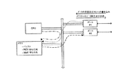
このシステムは、図4のシステムと類似したものである。この図6のシステムにおいて、パケット/セルが受信されると、該パケット/セルは、各I/Oモジュール上のメモリ並びにCPU/FEメモリ内に格納される。CPU/FEによりアクセスすることが可能なメモリ内にデータが受信されると、該CPU/FEが制御情報を読み出してデータのデスティネーションとなるポートを決定する。該ポートが決定されると、それが各I/Oモジュール上に書き込まれて、該データを棄却すべきか維持すべきかが示される。したがって、このアーキテクチャは、CPU/FEメモリに関する幾分かの競合を軽減させ、これにより待ち時間が幾分か低減されるが、その代わりにメインシステムバスに多くの競合が生成される。これは、各I/Oモジュールが他のI/Oモジュールに関するデータをその必要性の有無に関わらず送信しなければならないからである。ポート及びデータ伝送速度が増大すると、CPU/FEモジュールのメモリスループットは、システム中の全ポートのデータ伝送速度よりも大きくなければならない。これは、図4及び図5に示す従来の2つの例と比較してメモリシステムのコスト及び複雑性を低減させるものであるが、あらゆるI/Oモジュール上に一層複雑で高コストの「モジュール」相互接続バス及びメモリを必要とし、このため、システム全体のコスト及び複雑性が増大することになる。コスト及び複雑性を増大させる他の要因として、あらゆるI/Oモジュールが、他のあらゆるI/Oモジュールからのデータを受信することができるよう十分なメモリを有していなければならないことが挙げられる。一般に、I/Oモジュール上のメモリスループットは、前述のように、そのポートのデータ伝送速度の2倍をサポートしていればよく、及びその待ち行列の管理をサポートしていればよい。このアーキテクチャでは、そのポートのデータ伝送速度の2倍及びその待ち行列の管理をサポートしていなければならず、更に、システム内の他のポートの全てのデータ伝送速度、及びこのデータに関する付加的な受信待ち行列の管理をサポートしていなければならない。ポート及びデータ伝送速度が増大すると、それに従って、あらゆるI/Oモジュール及びCPU/FEモジュール上のメモリシステムのスループットが増大しなければならず、このため、この種のアーキテクチャのスケーラビリティが制限されることになる。
【0031】
各ポート毎に多数の待ち行列を維持することを必要とするQOSを提供する場合、このアーキテクチャは、待ち行列にアクセスするための競合の増大に起因して待ち時間を増大させるものとなる。
【0032】
マルチキャストサポートを提供する場合には、このアーキテクチャは、同一のパケットを各I/Oモジュールに同時に送信することができるという点では従来の例よりも良好なものであるが、1回のアクセスでパケット全体を送信することができないため、それに従って待ち時間が増大する。したがって、このアーキテクチャは、待ち時間の幾分かの内部的な低減を提供するものとなるが、これは、一層高いメモリスループット、1I/Oモジュールあたりのコスト及び複雑性の増大という犠牲の下で実現されるものである。
【0033】
更に、このシステムの場合も、パケット/セルがメモリ中に完全に書き込まれるまで制御情報及び待ち行列の処理を開始することができないため、ゼロ待ち時間の達成が不可能となる。
図7のタイプのネットワーク
図7に示すようなクロスバーを用いる場合には、セルは、典型的には入力で処理され、及び該セルがクロスバー内で効率的にスイッチングされることを可能にする内部ヘッダが与えられる。クロスバーは、該内部ヘッダを用いてセルをどの出力ポートにスイッチングすべきかを決定することになる。複数のセルが同一の出力を宛先とする場合には、クロスバー内の出力又は入力において更なるバッファリングが必要となる。殆どのクロスバーアーキテクチャは、セルのみと共に用いられる。これは、かかるアーキテクチャが、単一の出力ポートを宛先とする複数の入力ポートやマルチキャストを含む幾つかの要因に起因するブロック化(blocking)という問題を一般に有するという事実に起因する。パケットが使用される場合、該パケットのサイズは64byteから64,000byteまで変化する可能性があり、これらのブロック化の問題は大きな問題となり、一般に該アーキテクチャを使用不能にするものとなる。
【0034】
入力ポートにおける初期のルックアップは、図4に関して説明した競合の問題を依然として有するものであり、セル全体が受信されるのを待った後にルックアップを実行しなければならず、この場合もシステムの待ち時間が増大する。セルがスイッチ内に入ると、待ち時間は、実施されるクロスバーのタイプによって決まるが、一般には、シリコンベースのクロスバーにおける多数のホップのトラバース(traversing)、又はメモリベースのクロスバーにおける共有メモリに関する競合から構成される。クロスバー内で内部的なブロック化が生じた場合には、更なる待ち時間が生じる可能性がある。
【0035】
QOSを提供する場合には、典型的には入力ポート又は出力ポートの何れかに待ち行列が設けられる。該待ち行列は、あらゆるポートに必要なものではなく、競合及び維持すべき待ち行列の数が低減され、待ち時間もまた低減される。
【0036】
マルチキャストサポートを提供する場合には、典型的にはクロスバー内でセルが複製され、その結果として、内部的に又は出力ポートでブロック化状況が発生し(及び待ち時間が増大し)、また入力ポートでバックプレッシャー(backpressure)が生じ、このため、入力ポートが更なるバッファ空間を提供することが必要となる。ポート及びデータ伝送速度が増大した場合、このアーキテクチャは、スケーリングすることができない。これは、マルチキャストにより、ブロック化の問題が悪化し、システムのコスト及び複雑性が一層増大するからである。
【0037】
このシステムの場合も、パケット/セルがメモリ中に完全に書き込まれるまで制御情報及び待ち行列の処理を開始することができないため、ゼロ待ち時間の達成が不可能となる。
本発明の好適実施例
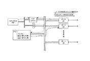
図8に例示する従来のものとは異なる本発明は、待ち時間を最小限にするようネットワーキングシステムを最適化し、実際に、データ伝送速度及びポート密度が増大された場合でさえ、ゼロ待ち時間を達成することが可能なものである。更に、本発明は、53byteのセル又は64〜64Kbyteのパケットについてもこれを達成する。これは、パケット/セルがメモリに書き込まれている際に該パケット/セルから制御情報を抽出し、及びメモリへのデータの書き込み時にスイッチング、ルーティング、及び/又はフィルタリングの決定を行う送出エンジンFEに前記制御情報を提供することにより、達成される。
【0038】
送出エンジンFEがそのタスクを終えた後、次いで、その結果が、待ち行列に対する出し入れを行うために待ち行列マネージャQMに与えられる。本発明によれば、これら全てが発生するのは、パケット/セルがメモリに完全に書き込まれる前であり、これにより、パケット/セルがメモリに完全に書き込まれた直後にデータの読み出しを開始させることが可能となる。実際に、パケットがメモリに完全に書き込まれる前に該パケットの読み出しを開始させることが可能であるが、これは、これまでメモリからの読み出し時に行うことはできなかった。不正なデータがメモリから読み出されることになるからである。パケット/セルの読み出しの開始が早すぎないことを保証するためには、図8に示すように出口ポートと入口ポートとの間の同期Sが必要となる。これは、送出エンジンFEが、最後のデータがメモリ中にあることを検出し、次いで意図される出口ポートについて待ち行列のアドレス情報を待ち行列マネージャQMに送る場合に達成される。これは、本発明と他の全てのネットワーキングアーキテクチャとの間の重要な相違点である。かかる他のアーキテクチャを用いる場合には、この競合条件は存在せず、したがって、既に指摘したように、それらでゼロ待ち時間を達成することは不可能である。
【0039】
該競合条件を防止するために、出口ポートと入口ポートとの間の同期Sが送出エンジンの出力で実施される(送出エンジンは、パケット/セルがメモリに完全に書き込まれるまで、その出力に結果を保持し、次いで、該結果を一点鎖線のフローラインで示すように待ち行列マネージャに送ることができる)。
【0040】
本発明では制御情報のために別個のパス又はデュアルパスが使用され、このため、各I/Oモジュール(#1〜#n)がそのポートのみについてデータを(該データが送信データであろうと受信データであろうと)処理することが可能となり、これにより、本発明のシステムは、今日の既存のシステムと比較して、必要となるロジックの複雑性がより低下し、一層単純で安価に実施することが可能なものとなる。前述のように、殆どのシステムは、システム内のあらゆるポートのデータ伝送速度の2倍よりも遙かに大きいデータ伝送速度をサポートするために、制御情報を格納するために使用されるメモリアーキテクチャを必要とする。一方、本発明は、そのI/Oモジュール上のあらゆるポートのデータ伝送速度に対する要件を低減させるものとなる(これは著しい低減となる)。本発明はまた、高コストで複雑な解決策を必要とすることなく、システムのポート及びデータ伝送速度の増大を可能にするものである。
【0041】
殆どの他のアーキテクチャでは、既述のように、パケット又はセルを格納するために使用される同一のメモリにアクセスするためにFE及び待ち行列マネージャが必要となり、その結果、待ち時間が増大することになる。これは、FE及び待ち行列マネージャがメモリアクセスに関して各ポートと競合しなければならないからである。しかし、本発明を用いた場合には、FE及び待ち行列マネージャは、制御情報を処理するための別個のパスPを有しており、これにより、それら2つのエンティティが最大限の性能で動作することが可能になり、メモリとの間のパケット/セルの伝送による干渉を受けることもなくなる。これは、実際に、ゼロ待ち時間を達成するために生じなければならないことである。
【0042】
図9から分かるように、本発明のシステムの待ち時間は、制御情報及び待ち行列の処理がメモリへのデータ書き込みから独立して行われる場合には、ゼロへと低減することが可能である。図9において(この場合も、メモリに対する1回の読み出し又は書き込みについてのアクセスタイムはMに等しく、1回のメモリアクセスについてのビット数はWである)、図8に示す本発明のデュアルパス処理により以下の事象が生じ、該図9は、特に前述の図3のA-E動作と対照をなすような形式をとったものである。
【0043】
A.受信ポート#1からメモリへのデータの書き込み。1パケット又はセルを伝送するための時間は((B×8)/W)×Mに等しい(Bは1パケット又はセルのバイト数)。パケットが大きくなると、該パケットをメモリへ書き込むための時間も長くなる。
【0044】
B.受信ポート#2からメモリへのデータの書き込み。1パケット又はセルを伝送するための時間は((C×8)/W)×Mに等しい(Cは1パケット又はセルのバイト数)。パケットが大きくなると、該パケットをメモリへ書き込むための時間も長くなる。
【0045】
C.メモリへのパケット又はセルの書き込み中に該パケット又はセルから制御情報が抽出される。該制御情報の処理は直ちに開始される。この処理の結果は、待ち行列マネージャに与えられる。該制御情報は、パケット/セルのヘッダから抽出されるので、必要となる情報のみが抽出される。これは、典型的には、パケット又はセルについて4〜10byteである。該制御情報の抽出に要する時間の量は((Y×8)/W)×Mとなる。ここで、Yは、制御情報がヘッダ内でまたがるバイト数(典型的には4〜24byte)である。送出エンジンは他の如何なるデバイスとも競合する必要がないので、制御情報の処理の開始時における遅延は全く存在しない、ということが理解されよう。この結果は、受信したばかりのパケット/セルの待ち時間に影響を与えるものではない。
【0046】
D.ポート#1から受信されたパケット/セルのバッファアドレスの適当な出口I/Oモジュールへの送出。該I/Oモジュール上で、待ち行列マネージャがバッファアドレスを適当な待ち行列に入れ、該待ち行列の最上部に現れた際に抽出することになる。この送出結果は典型的には4〜10byteとなる。該結果を待ち行列マネージャに送るための時間は((Z×8)/R)×Sとなる。ここで、Zは送出結果の長さ、Rは該結果をFEから待ち行列マネージャに送るために使用されるバスの幅、及びSは同じバスのクロック速度である。メモリとの間でのパケット/セルの伝送は送出結果の送信に干渉しないものであることが理解されよう。この結果は、受信したばかりのパケット/セルの待ち時間に影響を与えるものではない。
【0047】
E.どの待ち行列が送信に利用可能なデータを有しているかを判定するための異なる待ち行列の読み出し。これは、ポート#1からのパケット/セルのバッファアドレスが送信可能な状態になるまで多数の待ち行列の読み出しを行うことからなる。読み出される各待ち行列エントリは典型的には8〜12byteとなる。待ち行列を更新するための時間は(F+1)(((P×8)/R)×S)となる(Fは最後にパケットが待ち行列から出される前に読み出された待ち行列の数)。待ち行列は分散され、読み出すべき待ち行列の数は、特定のI/Oモジュール(システム全体ではない)をサポートするための待ち行列の数まで低減される。これは、異なる待ち行列をスキャンするために要する時間量を低減させ、したがってゼロ待ち時間の達成を支援するものとなる。メモリとの間でのパケット/セルの伝送は、待ち行列からのバッファアドレスの取り出しに干渉しないものであることが理解されよう。この結果は、受信したばかりのパケット/セルの待ち時間に影響を与えるものではない。
【0048】
F.メモリから受信ポート#2へのデータの読み出し。1パケット又はセルを伝送するための時間は((B×8)/W)×Mに等しい(Bは1パケット又はセルのバイト数)。パケットが大きくなると、該パケットをメモリから読み出すための時間も長くなる。
【0049】
前述のように1ポートにつき多数の待ち行列を維持することを必要とするQOSを提供する場合には、本アーキテクチャは、待ち行列マネージャをN個の独立したサブ待ち行列マネージャへと分割することを可能にする。この場合、各サブ待ち行列マネージャは、関連するI/Oモジュールについて待ち行列を処理することを責務とするものとなる。これにより、システムのポート及びデータ伝送速度が増大された場合に拡張することが可能な単純で安価な実施態様が可能となり、これもまた、システムのゼロ待ち時間の達成を可能にするものとなる。
【0050】
また、マルチキャストサポートを提供する場合には、本発明のアーキテクチャは、単純で安価な実施態様を用いることができるように送出及び待ち行列の決定を行うために必要となる最小限の量の情報を送るという点で最適な解決策を提供するものとなる。待ち行列マネージャが「サブ待ち行列マネージャ」から構成されるため、マルチキャスト情報を各サブ待ち行列マネージャへ同時に与えることができ、これにより、競合が排除され、ゼロ待ち時間が達成される。
【0051】
したがって、本発明は、待ち時間を最小限にするための最適な解決策を提供し、該解決策は、ポート及びデータ伝送速度の増大に伴って拡張可能である一方、単純で安価な実施形態しか必要としないものとなる。
【0052】
本発明の最終的な結果は、送出エンジンは、各パケット/セルの制御情報を処理する際に他のリソースと競合する必要がない、ということであり、実際に、送出エンジンは、そのI/Oモジュール内のデータを処理するだけでよく、一層単純で複雑性の低いものとすることができる。待ち行列マネージャもまた、各パケット/セルの待ち行列の送受信を行う処理する際に他のリソースと競合する必要がなく、実際に、待ち行列マネージャは、そのI/Oモジュール内のデータを処理するだけでよく、やはり一層単純で複雑性の低いものとすることが可能となる。
【0053】
更に、本発明の場合には、データと制御情報との間に競合が存在せず、待ち行列が効率的に処理され、並びにマルチキャストサポートが提供される。本最終的な結果は、待ち時間を劇的に低減させるアーキテクチャとなる。本発明を前記の同時係属中の米国特許出願第581,467号の帯域幅最適化構造と組み合わせると、最適帯域幅及び最小待ち時間を有するネットワークが得られることになる。
【0054】
当業者であれば更なる修正例を実施することが可能であり、かかる実施は、特許請求の範囲に係る本発明の思想及び範囲内に含まれるものである。
【図面の簡単な説明】
【図1】 従来の典型的なパケット/セル構造及び現行のネットワーキングシステムを示すブロック図である。
【図2】 例示としての典型的な従来のネットワーク中のシステムを示す同様のブロック図である。
【図3】 競合が如何にして待ち時間を生成するかを示す説明図である。
【図4】 典型的な従来の多数のI/Oポートを有する共有メモリシステムを示すブロック図である。
【図5】 「ヘッダ」キャッシュを有する修正された共有メモリシステムを示すブロック図である。
【図6】 従来の典型的な分散型メモリシステム及び現行のネットワーキングシステムを示す同様のブロック図である。
【図7】 ネットワーキングシステムで使用される典型的なクロスバーシステムを示すブロック図である。
【図8】 本発明の好適なパケット/セルデュアルパスデータ処理及び管理アーキテクチャを示すブロック図である。
【図9】 本発明により如何に待ち時間が低減されるかを示す説明図である。[0001]
BACKGROUND OF THE INVENTION
The present invention relates to networking systems and the sending and routing of information within them, and more particularly to system latency issues due to contention for access to shared memory and the time required to make sending and / or routing decisions. Concerning time minimization.
[0002]
[Prior art]
Two of the main factors and concerns required for system performance in networking systems are generally bandwidth capacity and system operation latency. The bandwidth reflects the amount of data that can be transmitted through the system, and the latency is related to the amount of time that the data “stays” in the system.
[0003]
The present invention relates to minimizing latency. Applicant's co-pending US Patent Application No. 581,467 (filed December 29, 1995) entitled “High Performance Universal Multi-Port Pnternally Cached Dynamic Random Access Memory System, Architecture and Method” Promising solutions are being provided to enable
[0004]
Network system latency is determined by several factors, one of which is the amount of time it takes to make a sending or routing decision as a result of examining control information at the beginning of a data packet or cell. . The control information differs depending on whether a cell or packet is involved. In the case of cells, switching decisions are made based on VCI / VPI information that can be used to map cells to egress interfaces in the system. On the other hand, in the case of a packet, a routing decision is made based on the destination (ie destination) address that can be used for mapping the packet to the egress interface. Further, in the case of packets, the source (ie source) address can be used to provide one level of filtering based on multiple pairs of source / destination address pairs, in which case A number of rules are set to determine if communication of the source / destination address pair is possible. If a packet that does not conform to such rules is received, the packet is discarded. For example, typically, data in this type of network is 53 bytes for cells and 64 to 64 Kbytes for packets.
[0005]
In conventional systems, processing of control information is performed by a central processing unit (CPU) and does not begin until the entire cell / packet is received. The waiting time of such a system is determined by the transmission of data from the I / O port to the memory, the access of the control information arranged at the beginning of the data, the update of the control information, and the transmission of the data from the memory to the I / O port. Determined. All of these shared memory accesses result in significant bus and memory contention, which increases latency. The latency is quite significant for this type of architecture. This is because the processing of control information cannot be started until the entire packet / cell is received. Other factors that increase latency include QOS (Quality of Service) and multicast support. QOS requires the maintenance of multiple queues for each I / O port, which increases the number of accesses to memory that is already overloaded. Multicast also requires transmission of the same packet / cell to a plurality of I / O ports, which also increases the number of accesses to an overloaded memory.
[0006]
Yet another factor that determines system latency is the shared memory throughput. If the shared memory throughput is not very high, the latency will increase accordingly. In general, to support full bandwidth, memory throughput needs to be equal to twice the port speed multiplied by the number of ports. However, this does not take into account all the other accesses that must be made to the same shared memory, so to minimize latency and achieve high bandwidth through the system. Requires higher memory throughput. Furthermore, as more ports are added and the speed of each port is increased, latency increases proportionally. Therefore, increasing the throughput of the shared memory system becomes a very difficult problem.
[0007]
As will be demonstrated later, the operation of most conventional networking systems is one that does not allow zero or nearly zero latency to be achieved. On the other hand, according to the present invention, the use of a novel packet / cell dual path data processing and management architecture can result in optimally minimized latency.
[0008]
[Problems to be solved by the invention]
Accordingly, it is an object of the present invention to provide a novel system architecture and method for dual path data processing and management, such as data packets and / or cells, that dramatically reduce latency.
[0009]
It is a further object of the present invention to achieve this new result of minimizing latency without competing with other resources while processing the control information for each packet / cell.
[0010]
Further objects of the present invention will be described below and will be described in detail in the claims.
[0011]
[Means for Solving the Problems]
In short, the present invention, in one important aspect thereof, is encompassed by a CPU or data control system, in which case data is interfaced along a common bus, which is connected to a common memory. Connected to a plurality of I / O modules for receiving and writing data packets / cells to and removing them from the memory. The present invention also includes a method for reducing memory access contention and the resulting system latency, the method comprising, for each I / O module, a corresponding delivery engine, transmission queue means, and A separate for extracting control information from the packet / cell received by the I / O module and providing the control information to the sending enginepathThe control information of the extracted packet / cell is processed by the transmission engine, and switching, routing, and / or filtering is determined when the data is written in the memory, and the processing result by the transmission engine Should be sent to the queue manager to send / receive queues to / from the receive and send queues of each packet / cell and send the packet / cell data via the send queue means of the corresponding I / O module The steps of controlling the interface with the appropriate egress I / O module and performing all of them without competing with the transmission of packet / cell data to and from the memory and independent of the data transmission. It is what you have.
[0012]
Preferred and best mode configurations and techniques are described in detail below.
[0013]
DETAILED DESCRIPTION OF THE INVENTION
Limiting latency in current network systems with prior art
As already mentioned, in a typical packet / cell configuration used with a network system, control information is placed at the beginning of the packet, as shown schematically in FIG. As already mentioned, switching decisions based on VCI / VPI information used to map cells to egress interfaces in the system are shown. Packet routing decisions are made based on the destination address used to map the packet to the egress interface.
[0014]
In the conventional system of FIG. 2, the CPU performs memory access and interfaces with a plurality of data reception and removal I /
[0015]
Further, as can be seen from FIG. 3, as the access to the shared memory increases, the contention also increases, and as the contention increases, the latency of the system increases. FIG. 3 shows the following functions (the access time for one read or write is equal to M and the number of bits for one memory access is W):
[0016]
A. Write data from receive
[0017]
B. Write data from receive
[0018]
C. Read control information from packets / cells written to shared memory from
[0019]
D. Write the packet / cell buffer address received from
[0020]
E. Reading different queues to determine which queue has data available for transmission. This consists of reading a number of queues until the packet / cell buffer address from
[0021]
F. Read data from shared memory to receive
[0022]
Of course, the goal of the system is to zero (or nearly zero) latency. When the latency is zero, there will be no time between writing the packet / cell from the egress interface to memory and reading the packet / cell from the memory for the egress interface. In fact, a race condition may exist if the egress interface is determined and the buffer address is dequeued before the packet / cell is completely written to memory. As a result of the race condition, reading of the data is started before the writing of data to the memory is completed, thereby transmitting illegal data. In a shared memory system, as described above, it is impossible to achieve zero latency because the control information and queue cannot be processed until the packet / cell is completely written to memory.
[0023]
Today's typical system seeks to reduce system latency by providing higher throughput of the system, which provides a gradual benefit in reducing latency. . However, providing high throughput within the system can only be achieved at the expense of cost and complexity. The bottom line (the lowest line, or the lowest number indicating profit or loss) is to increase the data transmission speed and density of the I / O ports, and the latency of such systems is not reduced, but actually increases. To do.
Figure 4 type network
Typical network devices such as switches, routers, bridges, hubs, routing switches, and switching routers are interconnected with multiple networks such as ATM, Token Ring, FDDI, Ethernet, and Sonet, as shown in FIG. . These network interconnections require a CPU or Forwarding Engine (FE) to determine from which port the packet / cell should be transmitted with reference to each packet or cell received by the system. As already mentioned, the CPU / FE must access the first part of each packet / cell to determine what type of data the packet / cell is and where it is destined for. I must. As data transmission rates and I / O ports increase, contention for the same memory resource also increases, thereby increasing system latency as previously described. The only solution to reduce latency is to reduce memory access time, which increases cost and complexity. In the case of a shared memory system, the performance of the memory system must be at least greater than twice the bandwidth of all ports. For example, if the system has N ports and each port has a data transmission rate V, the total bandwidth of the memory system must be greater than 2 NV. Since the memory system must also support control information lookups and modifications, as well as possible queue management and routing table lookups, the total bandwidth must be greater than 2 NV. This suppresses performance scalability (ie, scalability and shrinkability) as the memory system must have a total bandwidth greater than 2 NV, and as a result limits scalability in reducing latency. It will be.
[0024]
In providing QOS, it is necessary to maintain a large number of queues per port, and as a result of this architecture, latency increases due to increased contention of queue access. Become. Of course, in this case, higher memory throughput is required, which increases cost and complexity.
[0025]
Also, when providing multicast support, the number of accesses to the shared memory will increase dramatically, contention and latency will increase significantly, and a higher throughput memory system will need to be designed.
[0026]
Also, this type of system cannot achieve zero latency because control information and queue processing cannot begin until the packet / cell is completely written to memory.
Network of the type shown in FIG.
FIG. 5 is similar to FIG. 4 except that a header cache is added to the front of the CPU / FE. Packets / cells are read / written into the shared memory structure as they are sent and received on each interface, in which case the first 64 bytes of the packet are “mirrored” in the header cache. . Since the first 64 bytes are copied into the header cache and one cell is 53 bytes, this architecture is only applicable to packet-based systems. When accessing the control information of the packet, the CPU / FE actually takes out data from the header cache instead of from the shared memory. This reduces contention for shared memory, but only for access to control information. Thus, this architecture provides a gradual improvement over the conventional architecture shown in FIG.
[0027]
However, as with conventional architectures, the memory system still needs to be greater than twice the throughput for each port. Writing data to the shared memory, processing control information, setting and maintaining a queue for each port, and reading data from the shared memory are still a series of accesses. As port and data transmission rates increase, memory throughput needs to be scaled (ie, expanded) to provide the same latency accordingly. This can only be achieved by increasing cost and complexity, which reaches a point where it becomes impractical due to cost limitations.
[0028]
When providing QOS that requires maintaining a large number of queues for each port, this architecture increases latency due to increased contention for accessing the queues. Again, higher memory throughput is required which also increases cost and complexity.
[0029]
In providing multicast support, this architecture requires increased access to shared memory, greatly increasing contention and latency, and designing higher throughput memory systems.
[0030]
Even with this system, it is impossible to achieve zero latency because control information and queue processing cannot begin until the packet is completely written into memory.
Figure 6 type network
This system is similar to the system of FIG. In the system of FIG. 6, when a packet / cell is received, the packet / cell is stored in the memory on each I / O module as well as in the CPU / FE memory. When data is received in a memory that can be accessed by the CPU / FE, the CPU / FE reads the control information and determines a port as a data destination. Once the port is determined, it is written on each I / O module to indicate whether the data should be rejected or maintained. Thus, this architecture alleviates some contention for CPU / FE memory, thereby reducing latency somewhat, but creates more contention on the main system bus instead. This is because each I / O module must transmit data regarding other I / O modules regardless of the necessity. As ports and data transmission rates increase, the CPU / FE module memory throughput must be greater than the data transmission rates of all ports in the system. This reduces the cost and complexity of the memory system compared to the two conventional examples shown in FIGS. 4 and 5, but is a more complex and costly “module” on any I / O module. Requires an interconnect bus and memory, which increases the overall cost and complexity of the system. Another factor that increases cost and complexity is that every I / O module must have enough memory to be able to receive data from every other I / O module. . Generally, the memory throughput on the I / O module only needs to support twice the data transmission rate of the port as described above, and only needs to support the management of the queue. This architecture must support twice the data rate of the port and the management of its queues, and in addition to all the data rates of other ports in the system, and additional data related to this data. Must support receive queue management. As the port and data transmission rates increase, the throughput of the memory system on every I / O module and CPU / FE module must increase accordingly, which limits the scalability of this type of architecture. become.
[0031]
When providing QOS that requires maintaining a large number of queues for each port, this architecture increases latency due to increased contention for accessing the queues.
[0032]
When providing multicast support, this architecture is better than the previous example in that the same packet can be sent to each I / O module at the same time. Since the whole cannot be transmitted, the latency increases accordingly. Thus, this architecture provides some internal reduction in latency, at the cost of higher memory throughput, cost per I / O module, and increased complexity. It is realized.
[0033]
Furthermore, even with this system, zero latency cannot be achieved because control information and queue processing cannot begin until the packet / cell is completely written into memory.
Figure 7 type of network
When using a crossbar as shown in FIG. 7, a cell is typically processed at the input, and an internal header is provided that allows the cell to be efficiently switched within the crossbar. . The crossbar will use the internal header to determine which output port the cell should be switched to. If multiple cells are destined for the same output, further buffering is required at the output or input in the crossbar. Most crossbar architectures are used with cells only. This is due to the fact that such architecture generally has the problem of blocking due to several factors including multiple input ports destined for a single output port and multicast. If a packet is used, the size of the packet can vary from 64 bytes to 64,000 bytes, and these blocking issues are a major problem and generally make the architecture unusable.
[0034]
The initial lookup at the input port still has the contention problem described with respect to FIG. 4, and the lookup must be performed after waiting for the entire cell to be received, again in the system wait. Time increases. When a cell enters the switch, latency is determined by the type of crossbar implemented, but in general, multiple hops traversing in a silicon-based crossbar, or shared memory in a memory-based crossbar Composed of conflicts. If internal blocking occurs within the crossbar, additional latency may occur.
[0035]
When providing QOS, a queue is typically provided at either the input port or the output port. The queue is not required for every port, the number of contention and queues to be maintained is reduced, and latency is also reduced.
[0036]
When providing multicast support, cells are typically replicated in the crossbar, resulting in a blocking situation (and increased latency) internally or at the output port, and ingress Back pressure occurs at the port, which requires the input port to provide more buffer space. This architecture cannot be scaled as the port and data transmission rates increase. This is because multicasting exacerbates the blocking problem and further increases system cost and complexity.
[0037]
Again, zero latency cannot be achieved in this system because control information and queue processing cannot begin until the packet / cell is completely written into memory.
Preferred embodiment of the present invention
The present invention, which differs from the prior art illustrated in FIG. 8, optimizes the networking system to minimize latency, and in fact, achieves zero latency even when the data transmission rate and port density are increased. It is possible to achieve. Furthermore, the present invention achieves this for 53 byte cells or 64 to 64 Kbyte packets. This is to the sending engine FE that extracts control information from the packet / cell when it is written to memory and makes switching, routing, and / or filtering decisions when writing data to the memory. This is achieved by providing the control information.
[0038]
After the dispatch engine FE has finished its task, the result is then given to the queue manager QM for taking in and out of the queue. In accordance with the present invention, all of this occurs before the packet / cell is completely written to memory, thereby starting to read data immediately after the packet / cell is completely written to memory. It becomes possible. In fact, it is possible to start reading a packet before it is completely written to memory, but this has not been possible before when reading from memory. This is because illegal data is read from the memory. In order to ensure that the start of packet / cell reading is not too early, a synchronization S between the egress port and the egress port is required as shown in FIG. This is achieved when the sending engine FE detects that the last data is in memory and then sends the queue address information to the queue manager QM for the intended exit port. This is an important difference between the present invention and all other networking architectures. When using such other architectures, this race condition does not exist and therefore it is impossible to achieve zero latency with them as already pointed out.
[0039]
To prevent the race condition, a synchronization S between the egress port and the ingress port is performed at the output of the sending engine (the sending engine will result in its output until the packet / cell is completely written to memory). And then the result can be sent to the queue manager as shown by the dashed line flow line).
[0040]
In the present invention, a separate path or dual path is used for control information, so that each I / O module (# 1- # n) receives data only for that port (whether the data is transmitted data or not). Data can be processed (whether data), which makes the system of the present invention less complex and requires less complexity and is simpler and cheaper to implement than existing systems today It will be possible. As mentioned above, most systems have a memory architecture that is used to store control information to support data transmission rates that are much greater than twice the data transmission rate of every port in the system. I need. On the other hand, the present invention reduces the requirement for the data transmission rate of every port on the I / O module (this is a significant reduction). The present invention also allows for increased system ports and data transmission rates without the need for costly and complex solutions.
[0041]
Most other architectures require an FE and a queue manager to access the same memory used to store the packet or cell, as described above, resulting in increased latency. become. This is because the FE and queue manager must contend with each port for memory access. However, with the present invention, the FE and queue manager have separate paths P for processing control information, so that these two entities operate at maximum performance. And no interference from the packet / cell transmission with the memory. This is actually what must happen to achieve zero latency.
[0042]
As can be seen from FIG. 9, the latency of the system of the present invention can be reduced to zero if the control information and queue processing is performed independently of writing data to the memory. In FIG. 9 (again, the access time for one read or write to the memory is equal to M, and the number of bits for one memory access is W), the dual pass processing of the present invention shown in FIG. The following events occur, and FIG. 9 takes a form that contrasts particularly with the AE operation of FIG. 3 described above.
[0043]
A. Write data from receive
[0044]
B. Write data to memory from receive
[0045]
C. Control information is extracted from the packet or cell while the packet or cell is being written to the memory. Processing of the control information is started immediately. The result of this processing is given to the queue manager. Since the control information is extracted from the packet / cell header, only necessary information is extracted. This is typically 4-10 bytes for a packet or cell. The amount of time required to extract the control information is ((Y × 8) / W) × M. Here, Y is the number of bytes (typically 4 to 24 bytes) that the control information spans in the header. It will be appreciated that there is no delay at the beginning of processing of the control information, since the delivery engine need not compete with any other device. This result does not affect the latency of the packet / cell just received.
[0046]
D. Send the packet / cell buffer address received from
[0047]
E. Reading different queues to determine which queue has data available for transmission. This consists of reading a number of queues until the packet / cell buffer address from
[0048]
F. Read data from memory to receive
[0049]
When providing a QOS that needs to maintain a large number of queues per port as described above, the architecture will divide the queue manager into N independent sub-queue managers. enable. In this case, each sub-queue manager is responsible for processing the queue for the associated I / O module. This allows for a simple and inexpensive implementation that can be scaled as system ports and data transmission rates are increased, which also allows the system to achieve zero latency. .
[0050]
Also, when providing multicast support, the architecture of the present invention provides the minimum amount of information required to make sending and queuing decisions so that a simple and inexpensive implementation can be used. It provides the best solution in terms of sending. Since the queue manager is composed of “sub-queue managers”, multicast information can be provided to each sub-queue manager at the same time, thereby eliminating contention and achieving zero latency.
[0051]
The present invention thus provides an optimal solution for minimizing latency, which can be scaled with increasing port and data transmission rates, while being a simple and inexpensive embodiment. It will only be necessary.
[0052]
The net result of the present invention is that the sending engine does not have to contend with other resources in processing the control information for each packet / cell, and in fact the sending engine does not have its I / It only needs to process the data in the O module, which can be simpler and less complex. The queue manager also does not have to contend with other resources when processing to send and receive queues for each packet / cell, and in fact the queue manager processes the data in its I / O module It is possible to make it simpler and less complicated.
[0053]
Furthermore, in the case of the present invention, there is no contention between data and control information, the queue is processed efficiently, and multicast support is provided. The net result is an architecture that dramatically reduces latency. Combining the present invention with the bandwidth optimization structure of the aforementioned co-pending US Patent Application No. 581,467 will result in a network with optimal bandwidth and minimum latency.
[0054]
Those skilled in the art can implement further modifications, and such implementation is within the spirit and scope of the claimed invention.
[Brief description of the drawings]
FIG. 1 is a block diagram illustrating a conventional typical packet / cell structure and an existing networking system.
FIG. 2 is a similar block diagram illustrating a system in an exemplary typical conventional network.
FIG. 3 is an illustration showing how contention generates latency.
FIG. 4 is a block diagram illustrating a typical conventional shared memory system having multiple I / O ports.
FIG. 5 is a block diagram illustrating a modified shared memory system having a “header” cache.
FIG. 6 is a similar block diagram illustrating a typical conventional distributed memory system and an existing networking system.
FIG. 7 is a block diagram illustrating an exemplary crossbar system used in a networking system.
FIG. 8 is a block diagram illustrating a preferred packet / cell dual path data processing and management architecture of the present invention.
FIG. 9 is an explanatory diagram showing how the waiting time is reduced according to the present invention.
Claims (20)
Applications Claiming Priority (3)
| Application Number | Priority Date | Filing Date | Title |
|---|---|---|---|
| US08/900,757 | 1997-07-25 | ||
| US08/900,757 US5918074A (en) | 1997-07-25 | 1997-07-25 | System architecture for and method of dual path data processing and management of packets and/or cells and the like |
| PCT/IB1998/001117 WO1999005826A1 (en) | 1997-07-25 | 1998-07-21 | Networking systems |
Publications (2)
| Publication Number | Publication Date |
|---|---|
| JP2001511575A JP2001511575A (en) | 2001-08-14 |
| JP4334760B2 true JP4334760B2 (en) | 2009-09-30 |
Family
ID=25413044
Family Applications (1)
| Application Number | Title | Priority Date | Filing Date |
|---|---|---|---|
| JP2000504685A Expired - Fee Related JP4334760B2 (en) | 1997-07-25 | 1998-07-21 | Networking system |
Country Status (10)
| Country | Link |
|---|---|
| US (1) | US5918074A (en) |
| EP (1) | EP1016246B1 (en) |
| JP (1) | JP4334760B2 (en) |
| CN (1) | CN1151639C (en) |
| AU (1) | AU738983B2 (en) |
| CA (1) | CA2297650C (en) |
| DE (1) | DE69820084T2 (en) |
| HK (1) | HK1031058A1 (en) |
| IL (1) | IL134221A (en) |
| WO (1) | WO1999005826A1 (en) |
Families Citing this family (122)
| Publication number | Priority date | Publication date | Assignee | Title |
|---|---|---|---|---|
| US6160811A (en) * | 1997-09-12 | 2000-12-12 | Gte Internetworking Incorporated | Data packet router |
| US6259699B1 (en) * | 1997-12-30 | 2001-07-10 | Nexabit Networks, Llc | System architecture for and method of processing packets and/or cells in a common switch |
| US6138219A (en) * | 1998-03-27 | 2000-10-24 | Nexabit Networks Llc | Method of and operating architectural enhancement for multi-port internally cached dynamic random access memory (AMPIC DRAM) systems, eliminating external control paths and random memory addressing, while providing zero bus contention for DRAM access |
| WO2000003522A1 (en) * | 1998-07-08 | 2000-01-20 | Broadcom Corporation | A method of sending packets between trunk ports of network switches |
| US6876653B2 (en) * | 1998-07-08 | 2005-04-05 | Broadcom Corporation | Fast flexible filter processor based architecture for a network device |
| US6430188B1 (en) | 1998-07-08 | 2002-08-06 | Broadcom Corporation | Unified table for L2, L3, L4, switching and filtering |
| US6272567B1 (en) * | 1998-11-24 | 2001-08-07 | Nexabit Networks, Inc. | System for interposing a multi-port internally cached DRAM in a control path for temporarily storing multicast start of packet data until such can be passed |
| US6498782B1 (en) | 1999-02-03 | 2002-12-24 | International Business Machines Corporation | Communications methods and gigabit ethernet communications adapter providing quality of service and receiver connection speed differentiation |
| US6765911B1 (en) * | 1999-02-03 | 2004-07-20 | International Business Machines Corporation | Communications adapter for implementing communications in a network and providing multiple modes of communications |
| US7120117B1 (en) | 2000-08-29 | 2006-10-10 | Broadcom Corporation | Starvation free flow control in a shared memory switching device |
| US6952401B1 (en) * | 1999-03-17 | 2005-10-04 | Broadcom Corporation | Method for load balancing in a network switch |
| DE60031515T2 (en) | 1999-03-17 | 2007-08-23 | Broadcom Corp., Irvine | NETWORK AGENCY |
| US7366171B2 (en) * | 1999-03-17 | 2008-04-29 | Broadcom Corporation | Network switch |
| US7643481B2 (en) | 1999-03-17 | 2010-01-05 | Broadcom Corporation | Network switch having a programmable counter |
| US6813268B1 (en) | 1999-05-21 | 2004-11-02 | Broadcom Corporation | Stacked network switch configuration |
| US7031302B1 (en) | 1999-05-21 | 2006-04-18 | Broadcom Corporation | High-speed stats gathering in a network switch |
| US6842457B1 (en) | 1999-05-21 | 2005-01-11 | Broadcom Corporation | Flexible DMA descriptor support |
| WO2000072533A1 (en) * | 1999-05-21 | 2000-11-30 | Broadcom Corporation | Stacked network switch configuration |
| US6879588B1 (en) | 1999-05-21 | 2005-04-12 | Broadcom Corporation | Address resolution snoop support for CPU |
| US6859454B1 (en) | 1999-06-30 | 2005-02-22 | Broadcom Corporation | Network switch with high-speed serializing/deserializing hazard-free double data rate switching |
| US7295552B1 (en) * | 1999-06-30 | 2007-11-13 | Broadcom Corporation | Cluster switching architecture |
| US7315552B2 (en) * | 1999-06-30 | 2008-01-01 | Broadcom Corporation | Frame forwarding in a switch fabric |
| US7082133B1 (en) | 1999-09-03 | 2006-07-25 | Broadcom Corporation | Apparatus and method for enabling voice over IP support for a network switch |
| US7143294B1 (en) * | 1999-10-29 | 2006-11-28 | Broadcom Corporation | Apparatus and method for secure field upgradability with unpredictable ciphertext |
| US7131001B1 (en) | 1999-10-29 | 2006-10-31 | Broadcom Corporation | Apparatus and method for secure filed upgradability with hard wired public key |
| US7539134B1 (en) * | 1999-11-16 | 2009-05-26 | Broadcom Corporation | High speed flow control methodology |
| WO2001037484A2 (en) * | 1999-11-16 | 2001-05-25 | Broadcom Corporation | Serializing data using hazard-free multilevel glitchless multiplexing |
| ATE344562T1 (en) * | 1999-11-18 | 2006-11-15 | Broadcom Corp | TABLE LOOKUP MECHANISM FOR ADDRESS RESOLUTION IN A PACKET NETWORK SWITCH |
| ATE265774T1 (en) | 1999-12-07 | 2004-05-15 | Broadcom Corp | MIRROR IN A NETWORK SWITCH STACK ARRANGEMENT |
| US6463067B1 (en) * | 1999-12-13 | 2002-10-08 | Ascend Communications, Inc. | Submission and response architecture for route lookup and packet classification requests |
| US7009973B2 (en) * | 2000-02-28 | 2006-03-07 | Broadcom Corporation | Switch using a segmented ring |
| US6810031B1 (en) | 2000-02-29 | 2004-10-26 | Celox Networks, Inc. | Method and device for distributing bandwidth |
| US6678678B2 (en) | 2000-03-09 | 2004-01-13 | Braodcom Corporation | Method and apparatus for high speed table search |
| US7103053B2 (en) * | 2000-05-03 | 2006-09-05 | Broadcom Corporation | Gigabit switch on chip architecture |
| US7222147B1 (en) | 2000-05-20 | 2007-05-22 | Ciena Corporation | Processing network management data in accordance with metadata files |
| US7266595B1 (en) | 2000-05-20 | 2007-09-04 | Ciena Corporation | Accessing network device data through user profiles |
| US6880086B2 (en) | 2000-05-20 | 2005-04-12 | Ciena Corporation | Signatures for facilitating hot upgrades of modular software components |
| US7143153B1 (en) | 2000-11-09 | 2006-11-28 | Ciena Corporation | Internal network device dynamic health monitoring |
| US7240364B1 (en) | 2000-05-20 | 2007-07-03 | Ciena Corporation | Network device identity authentication |
| US7225244B2 (en) | 2000-05-20 | 2007-05-29 | Ciena Corporation | Common command interface |
| US7111053B1 (en) | 2000-05-20 | 2006-09-19 | Ciena Corporation | Template-driven management of telecommunications network via utilization of operations support services clients |
| US7062642B1 (en) * | 2000-05-20 | 2006-06-13 | Ciena Corporation | Policy based provisioning of network device resources |
| US6601186B1 (en) | 2000-05-20 | 2003-07-29 | Equipe Communications Corporation | Independent restoration of control plane and data plane functions |
| US6639910B1 (en) | 2000-05-20 | 2003-10-28 | Equipe Communications Corporation | Functional separation of internal and external controls in network devices |
| US6934749B1 (en) | 2000-05-20 | 2005-08-23 | Ciena Corporation | Tracking distributed data retrieval in a network device |
| US6760339B1 (en) | 2000-05-20 | 2004-07-06 | Equipe Communications Corporation | Multi-layer network device in one telecommunications rack |
| US7054272B1 (en) | 2000-07-11 | 2006-05-30 | Ciena Corporation | Upper layer network device including a physical layer test port |
| US6715097B1 (en) | 2000-05-20 | 2004-03-30 | Equipe Communications Corporation | Hierarchical fault management in computer systems |
| US7051097B1 (en) | 2000-05-20 | 2006-05-23 | Ciena Corporation | Embedded database for computer system management |
| US6708291B1 (en) | 2000-05-20 | 2004-03-16 | Equipe Communications Corporation | Hierarchical fault descriptors in computer systems |
| US6671699B1 (en) | 2000-05-20 | 2003-12-30 | Equipe Communications Corporation | Shared database usage in network devices |
| US7225240B1 (en) | 2000-05-20 | 2007-05-29 | Ciena Corporation | Decoupling processes from hardware with logical identifiers |
| US6868092B1 (en) | 2000-05-20 | 2005-03-15 | Ciena Corporation | Network device with embedded timing synchronization |
| US7020696B1 (en) | 2000-05-20 | 2006-03-28 | Ciena Corp. | Distributed user management information in telecommunications networks |
| US6742134B1 (en) | 2000-05-20 | 2004-05-25 | Equipe Communications Corporation | Maintaining a local backup for data plane processes |
| US6876652B1 (en) | 2000-05-20 | 2005-04-05 | Ciena Corporation | Network device with a distributed switch fabric timing system |
| US6332198B1 (en) | 2000-05-20 | 2001-12-18 | Equipe Communications Corporation | Network device for supporting multiple redundancy schemes |
| US7349960B1 (en) | 2000-05-20 | 2008-03-25 | Ciena Corporation | Throttling distributed statistical data retrieval in a network device |
| US6658579B1 (en) | 2000-05-20 | 2003-12-02 | Equipe Communications Corporation | Network device with local timing systems for automatic selection between redundant, synchronous central timing systems |
| US6654903B1 (en) | 2000-05-20 | 2003-11-25 | Equipe Communications Corporation | Vertical fault isolation in a computer system |
| US7039046B1 (en) | 2000-05-20 | 2006-05-02 | Ciena Corporation | Network device including central and distributed switch fabric subsystems |
| US7280529B1 (en) | 2000-05-20 | 2007-10-09 | Ciena Corporation | Providing network management access through user profiles |
| US6826561B2 (en) | 2000-05-22 | 2004-11-30 | Broadcom Corporation | Method and apparatus for performing a binary search on an expanded tree |
| EP1162792B1 (en) * | 2000-06-09 | 2012-08-15 | Broadcom Corporation | Gigabit switch with frame forwarding and address learning |
| EP1168725B1 (en) | 2000-06-19 | 2005-06-15 | Broadcom Corporation | Switch fabric with path redundancy |
| US7126947B2 (en) * | 2000-06-23 | 2006-10-24 | Broadcom Corporation | Switch having external address resolution interface |
| US6999455B2 (en) * | 2000-07-25 | 2006-02-14 | Broadcom Corporation | Hardware assist for address learning |
| US7330877B2 (en) * | 2000-09-18 | 2008-02-12 | Sharp Laboratories Of America | Devices, softwares and methods for rescheduling multi-party sessions upon premature termination of session |
| US7227862B2 (en) * | 2000-09-20 | 2007-06-05 | Broadcom Corporation | Network switch having port blocking capability |
| US7120155B2 (en) * | 2000-10-03 | 2006-10-10 | Broadcom Corporation | Switch having virtual shared memory |
| US6988177B2 (en) * | 2000-10-03 | 2006-01-17 | Broadcom Corporation | Switch memory management using a linked list structure |
| US7020166B2 (en) * | 2000-10-03 | 2006-03-28 | Broadcom Corporation | Switch transferring data using data encapsulation and decapsulation |
| US6851000B2 (en) * | 2000-10-03 | 2005-02-01 | Broadcom Corporation | Switch having flow control management |
| US7274705B2 (en) * | 2000-10-03 | 2007-09-25 | Broadcom Corporation | Method and apparatus for reducing clock speed and power consumption |
| US7420977B2 (en) * | 2000-10-03 | 2008-09-02 | Broadcom Corporation | Method and apparatus of inter-chip bus shared by message passing and memory access |
| US7424012B2 (en) * | 2000-11-14 | 2008-09-09 | Broadcom Corporation | Linked network switch configuration |
| US7035286B2 (en) * | 2000-11-14 | 2006-04-25 | Broadcom Corporation | Linked network switch configuration |
| US7035255B2 (en) * | 2000-11-14 | 2006-04-25 | Broadcom Corporation | Linked network switch configuration |
| US6850542B2 (en) * | 2000-11-14 | 2005-02-01 | Broadcom Corporation | Linked network switch configuration |
| US6647443B1 (en) * | 2000-12-28 | 2003-11-11 | Intel Corporation | Multi-queue quality of service communication device |
| US7042843B2 (en) * | 2001-03-02 | 2006-05-09 | Broadcom Corporation | Algorithm for time based queuing in network traffic engineering |
| US6976072B2 (en) * | 2001-03-30 | 2005-12-13 | Sharp Laboratories Of America, Inc. | Method and apparatus for managing job queues |
| US7263597B2 (en) | 2001-04-19 | 2007-08-28 | Ciena Corporation | Network device including dedicated resources control plane |
| US20020184381A1 (en) * | 2001-05-30 | 2002-12-05 | Celox Networks, Inc. | Method and apparatus for dynamically controlling data flow on a bi-directional data bus |
| US7187685B2 (en) * | 2001-08-09 | 2007-03-06 | International Business Machines Corporation | Multi-module switching system |
| US7274692B1 (en) * | 2001-10-01 | 2007-09-25 | Advanced Micro Devices, Inc. | Method and apparatus for routing packets that have multiple destinations |
| US7221678B1 (en) * | 2001-10-01 | 2007-05-22 | Advanced Micro Devices, Inc. | Method and apparatus for routing packets |
| US7295563B2 (en) * | 2001-10-01 | 2007-11-13 | Advanced Micro Devices, Inc. | Method and apparatus for routing packets that have ordering requirements |
| US7355970B2 (en) * | 2001-10-05 | 2008-04-08 | Broadcom Corporation | Method and apparatus for enabling access on a network switch |
| US20030074473A1 (en) * | 2001-10-12 | 2003-04-17 | Duc Pham | Scalable network gateway processor architecture |
| US7283538B2 (en) * | 2001-10-12 | 2007-10-16 | Vormetric, Inc. | Load balanced scalable network gateway processor architecture |
| US7424019B1 (en) | 2001-11-27 | 2008-09-09 | Marvell Israel (M.I.S.L) Ltd. | Packet header altering device |
| US20030105830A1 (en) * | 2001-12-03 | 2003-06-05 | Duc Pham | Scalable network media access controller and methods |
| KR100428773B1 (en) * | 2002-01-21 | 2004-04-28 | 삼성전자주식회사 | Router System and Method for Duplication of Forwarding Engine Utilizing |
| US7197553B2 (en) * | 2002-04-19 | 2007-03-27 | Nortel Networks Limited | Network system having a virtual-service-module |
| US7804785B2 (en) * | 2002-04-19 | 2010-09-28 | Avaya Inc. | Network system having an instructional sequence for performing packet processing and optimizing the packet processing |
| US7246178B2 (en) * | 2002-05-07 | 2007-07-17 | Nortel Networks Limited | Methods and systems for changing a topology of a network |
| US7386628B1 (en) | 2002-05-08 | 2008-06-10 | Nortel Networks Limited | Methods and systems for processing network data packets |
| CN100354843C (en) * | 2002-05-24 | 2007-12-12 | 皇家飞利浦电子股份有限公司 | Pseudo multiport data memory having stall facility |
| US7334124B2 (en) * | 2002-07-22 | 2008-02-19 | Vormetric, Inc. | Logical access block processing protocol for transparent secure file storage |
| US6931530B2 (en) | 2002-07-22 | 2005-08-16 | Vormetric, Inc. | Secure network file access controller implementing access control and auditing |
| US6678828B1 (en) * | 2002-07-22 | 2004-01-13 | Vormetric, Inc. | Secure network file access control system |
| US6754744B2 (en) | 2002-09-10 | 2004-06-22 | Broadcom Corporation | Balanced linked lists for high performance data buffers in a network device |
| JP4023281B2 (en) * | 2002-10-11 | 2007-12-19 | 株式会社日立製作所 | Packet communication apparatus and packet switch |
| US7143288B2 (en) | 2002-10-16 | 2006-11-28 | Vormetric, Inc. | Secure file system server architecture and methods |
| US20040114536A1 (en) * | 2002-10-16 | 2004-06-17 | O'rourke Aidan | Method for communicating information on fast and slow paths |
| JP4157403B2 (en) * | 2003-03-19 | 2008-10-01 | 株式会社日立製作所 | Packet communication device |
| US8103800B2 (en) * | 2003-06-26 | 2012-01-24 | Broadcom Corporation | Method and apparatus for multi-chip address resolution lookup synchronization in a network environment |
| US7697432B2 (en) * | 2003-06-27 | 2010-04-13 | Broadcom Corporation | Equal and weighted cost multipath load balancing in a network device |
| US7904584B2 (en) * | 2004-02-12 | 2011-03-08 | Broadcom Corporation | Source identifier-based trunking for systems of network devices |
| JP4008911B2 (en) * | 2004-09-29 | 2007-11-14 | 株式会社東芝 | Control device |
| US20060114907A1 (en) * | 2004-11-30 | 2006-06-01 | Broadcom Corporation | Cut-through switching in a network device |
| US7733868B2 (en) | 2005-01-26 | 2010-06-08 | Internet Broadcasting Corp. | Layered multicast and fair bandwidth allocation and packet prioritization |
| US8228932B2 (en) * | 2005-02-18 | 2012-07-24 | Broadcom Corporation | Layout architecture for expandable network device |
| US20060294317A1 (en) * | 2005-06-22 | 2006-12-28 | Berke Stuart A | Symmetric multiprocessor architecture with interchangeable processor and IO modules |
| JP4974078B2 (en) * | 2007-07-26 | 2012-07-11 | Necアクセステクニカ株式会社 | Data processing device |
| CN102204174A (en) * | 2008-11-04 | 2011-09-28 | 株式会社自动网络技术研究所 | Communication device, relay device, communication system, and communication method |
| CN102582269A (en) * | 2012-02-09 | 2012-07-18 | 珠海天威技术开发有限公司 | Memory chip and data communication method, consumable container and imaging device of memory chip |
| US11275632B2 (en) | 2018-09-14 | 2022-03-15 | Advanced Micro Devices, Inc. | Broadcast command and response |
| CN113010173A (en) | 2019-12-19 | 2021-06-22 | 超威半导体(上海)有限公司 | Method for matrix data broadcasting in parallel processing |
| CN113094099A (en) | 2019-12-23 | 2021-07-09 | 超威半导体(上海)有限公司 | Matrix data broadcast architecture |
| US11403221B2 (en) | 2020-09-24 | 2022-08-02 | Advanced Micro Devices, Inc. | Memory access response merging in a memory hierarchy |
Family Cites Families (8)
| Publication number | Priority date | Publication date | Assignee | Title |
|---|---|---|---|---|
| US5313582A (en) * | 1991-04-30 | 1994-05-17 | Standard Microsystems Corporation | Method and apparatus for buffering data within stations of a communication network |
| US5715407A (en) * | 1992-03-06 | 1998-02-03 | Rambus, Inc. | Process and apparatus for collision detection on a parallel bus by monitoring a first line of the bus during even bus cycles for indications of overlapping packets |
| US5309432A (en) * | 1992-05-06 | 1994-05-03 | At&T Bell Laboratories | High-speed packet switch |
| JPH07321815A (en) * | 1994-05-24 | 1995-12-08 | Nec Corp | Shared buffer type atm switch and its multi-address control method |
| EP0692893B1 (en) * | 1994-07-12 | 2000-03-01 | Ascom AG | Equipment for switching in digital ATM networks |
| US5513134A (en) * | 1995-02-21 | 1996-04-30 | Gte Laboratories Incorporated | ATM shared memory switch with content addressing |
| US5752078A (en) * | 1995-07-10 | 1998-05-12 | International Business Machines Corporation | System for minimizing latency data reception and handling data packet error if detected while transferring data packet from adapter memory to host memory |
| US5799209A (en) * | 1995-12-29 | 1998-08-25 | Chatter; Mukesh | Multi-port internally cached DRAM system utilizing independent serial interfaces and buffers arbitratively connected under a dynamic configuration |
-
1997
- 1997-07-25 US US08/900,757 patent/US5918074A/en not_active Expired - Lifetime
-
1998
- 1998-07-21 CN CNB988075792A patent/CN1151639C/en not_active Expired - Fee Related
- 1998-07-21 AU AU82366/98A patent/AU738983B2/en not_active Ceased
- 1998-07-21 EP EP98932442A patent/EP1016246B1/en not_active Expired - Lifetime
- 1998-07-21 WO PCT/IB1998/001117 patent/WO1999005826A1/en active IP Right Grant
- 1998-07-21 DE DE69820084T patent/DE69820084T2/en not_active Expired - Fee Related
- 1998-07-21 JP JP2000504685A patent/JP4334760B2/en not_active Expired - Fee Related
- 1998-07-21 IL IL13422198A patent/IL134221A/en not_active IP Right Cessation
- 1998-07-21 CA CA002297650A patent/CA2297650C/en not_active Expired - Fee Related
-
2001
- 2001-03-13 HK HK01101793A patent/HK1031058A1/en not_active IP Right Cessation
Also Published As
| Publication number | Publication date |
|---|---|
| DE69820084D1 (en) | 2004-01-08 |
| IL134221A (en) | 2004-06-01 |
| EP1016246B1 (en) | 2003-11-26 |
| HK1031058A1 (en) | 2001-05-25 |
| IL134221A0 (en) | 2001-04-30 |
| DE69820084T2 (en) | 2004-09-02 |
| CN1151639C (en) | 2004-05-26 |
| AU8236698A (en) | 1999-02-16 |
| JP2001511575A (en) | 2001-08-14 |
| US5918074A (en) | 1999-06-29 |
| CN1267418A (en) | 2000-09-20 |
| CA2297650A1 (en) | 1999-02-04 |
| EP1016246A1 (en) | 2000-07-05 |
| AU738983B2 (en) | 2001-10-04 |
| CA2297650C (en) | 2007-11-27 |
| WO1999005826A1 (en) | 1999-02-04 |
Similar Documents
| Publication | Publication Date | Title |
|---|---|---|
| JP4334760B2 (en) | Networking system | |
| JP2622055B2 (en) | Packet switching device and control method thereof | |
| JP3789395B2 (en) | Packet processing device | |
| EP0680173B1 (en) | Multicasting apparatus | |
| US4991172A (en) | Design of a high speed packet switching node | |
| US6147999A (en) | ATM switch capable of routing IP packet | |
| KR100664778B1 (en) | Flexible telecommunications switching network | |
| EP0680179B1 (en) | Multicasting apparatus | |
| EP0849917B1 (en) | Switching system | |
| JP3640299B2 (en) | A proposal and response architecture for route lookup and packet classification requests | |
| US20040151197A1 (en) | Priority queue architecture for supporting per flow queuing and multiple ports | |
| US7859999B1 (en) | Memory load balancing for single stream multicast | |
| JP2002501311A (en) | Network king system | |
| US5825774A (en) | Packet characterization using code vectors | |
| US6735207B1 (en) | Apparatus and method for reducing queuing memory access cycles using a distributed queue structure | |
| US6643294B1 (en) | Distributed control merged buffer ATM switch | |
| US5748633A (en) | Method and apparatus for the concurrent reception and transmission of packets in a communications internetworking device | |
| US7461167B1 (en) | Method for multicast service in a crossbar switch | |
| US20030235189A1 (en) | Pointer allocation by prime numbers | |
| US7505422B1 (en) | Preference programmable first-one detector and quadrature based random grant generator | |
| JP2002344514A (en) | Multi-cast method and device thereof | |
| WO2002003206A2 (en) | Multientity queue pointer chain tehnique | |
| KR100429907B1 (en) | Router and routing method for combined unicast and multicast traffic | |
| JP2001024702A (en) | Packet multiplexer and multiplexing method | |
| JP2001086124A (en) | Method for selecting atm cell waiting in queue and circuit device |
Legal Events
| Date | Code | Title | Description |
|---|---|---|---|
| A521 | Request for written amendment filed |
Free format text: JAPANESE INTERMEDIATE CODE: A523 Effective date: 20040726 |
|
| A621 | Written request for application examination |
Free format text: JAPANESE INTERMEDIATE CODE: A621 Effective date: 20040726 |
|
| A977 | Report on retrieval |
Free format text: JAPANESE INTERMEDIATE CODE: A971007 Effective date: 20060831 |
|
| A131 | Notification of reasons for refusal |
Free format text: JAPANESE INTERMEDIATE CODE: A131 Effective date: 20061003 |
|
| A601 | Written request for extension of time |
Free format text: JAPANESE INTERMEDIATE CODE: A601 Effective date: 20061228 |
|
| A602 | Written permission of extension of time |
Free format text: JAPANESE INTERMEDIATE CODE: A602 Effective date: 20070111 |
|
| A521 | Request for written amendment filed |
Free format text: JAPANESE INTERMEDIATE CODE: A523 Effective date: 20070403 |
|
| A02 | Decision of refusal |
Free format text: JAPANESE INTERMEDIATE CODE: A02 Effective date: 20080304 |
|
| A521 | Request for written amendment filed |
Free format text: JAPANESE INTERMEDIATE CODE: A523 Effective date: 20080702 |
|
| A911 | Transfer to examiner for re-examination before appeal (zenchi) |
Free format text: JAPANESE INTERMEDIATE CODE: A911 Effective date: 20081010 |
|
| TRDD | Decision of grant or rejection written | ||
| A01 | Written decision to grant a patent or to grant a registration (utility model) |
Free format text: JAPANESE INTERMEDIATE CODE: A01 Effective date: 20090526 |
|
| A01 | Written decision to grant a patent or to grant a registration (utility model) |
Free format text: JAPANESE INTERMEDIATE CODE: A01 |
|
| A61 | First payment of annual fees (during grant procedure) |
Free format text: JAPANESE INTERMEDIATE CODE: A61 Effective date: 20090624 |
|
| FPAY | Renewal fee payment (event date is renewal date of database) |
Free format text: PAYMENT UNTIL: 20120703 Year of fee payment: 3 |
|
| R150 | Certificate of patent or registration of utility model |
Free format text: JAPANESE INTERMEDIATE CODE: R150 |
|
| FPAY | Renewal fee payment (event date is renewal date of database) |
Free format text: PAYMENT UNTIL: 20120703 Year of fee payment: 3 |
|
| FPAY | Renewal fee payment (event date is renewal date of database) |
Free format text: PAYMENT UNTIL: 20130703 Year of fee payment: 4 |
|
| R250 | Receipt of annual fees |
Free format text: JAPANESE INTERMEDIATE CODE: R250 |
|
| R250 | Receipt of annual fees |
Free format text: JAPANESE INTERMEDIATE CODE: R250 |
|
| R250 | Receipt of annual fees |
Free format text: JAPANESE INTERMEDIATE CODE: R250 |
|
| LAPS | Cancellation because of no payment of annual fees |