JP4324043B2 - Image processing apparatus and method - Google Patents
Image processing apparatus and method Download PDFInfo
- Publication number
- JP4324043B2 JP4324043B2 JP2004208882A JP2004208882A JP4324043B2 JP 4324043 B2 JP4324043 B2 JP 4324043B2 JP 2004208882 A JP2004208882 A JP 2004208882A JP 2004208882 A JP2004208882 A JP 2004208882A JP 4324043 B2 JP4324043 B2 JP 4324043B2
- Authority
- JP
- Japan
- Prior art keywords
- color
- image
- area
- importance
- correction
- Prior art date
- Legal status (The legal status is an assumption and is not a legal conclusion. Google has not performed a legal analysis and makes no representation as to the accuracy of the status listed.)
- Expired - Fee Related
Links
- 238000012545 processing Methods 0.000 title claims description 40
- 238000000034 method Methods 0.000 title description 52
- 238000012937 correction Methods 0.000 claims description 121
- 238000000605 extraction Methods 0.000 claims description 13
- 230000007423 decrease Effects 0.000 claims description 5
- 239000000284 extract Substances 0.000 claims description 4
- 238000003672 processing method Methods 0.000 claims 8
- 239000003086 colorant Substances 0.000 description 15
- 230000008569 process Effects 0.000 description 14
- 230000006870 function Effects 0.000 description 13
- 230000014509 gene expression Effects 0.000 description 10
- 238000010586 diagram Methods 0.000 description 8
- 230000005484 gravity Effects 0.000 description 6
- 238000001514 detection method Methods 0.000 description 5
- 210000001508 eye Anatomy 0.000 description 5
- 238000003702 image correction Methods 0.000 description 5
- 230000002776 aggregation Effects 0.000 description 4
- 238000004220 aggregation Methods 0.000 description 4
- 241000282412 Homo Species 0.000 description 3
- 238000006243 chemical reaction Methods 0.000 description 3
- 238000011156 evaluation Methods 0.000 description 3
- 210000004709 eyebrow Anatomy 0.000 description 3
- 210000000744 eyelid Anatomy 0.000 description 3
- 238000012804 iterative process Methods 0.000 description 3
- KNMAVSAGTYIFJF-UHFFFAOYSA-N 1-[2-[(2-hydroxy-3-phenoxypropyl)amino]ethylamino]-3-phenoxypropan-2-ol;dihydrochloride Chemical compound Cl.Cl.C=1C=CC=CC=1OCC(O)CNCCNCC(O)COC1=CC=CC=C1 KNMAVSAGTYIFJF-UHFFFAOYSA-N 0.000 description 2
- 239000011159 matrix material Substances 0.000 description 2
- 238000012986 modification Methods 0.000 description 2
- 230000004048 modification Effects 0.000 description 2
- 235000012736 patent blue V Nutrition 0.000 description 2
- 241000196324 Embryophyta Species 0.000 description 1
- 241000375392 Tana Species 0.000 description 1
- 238000004458 analytical method Methods 0.000 description 1
- 238000013459 approach Methods 0.000 description 1
- 230000015556 catabolic process Effects 0.000 description 1
- 230000003247 decreasing effect Effects 0.000 description 1
- 230000000694 effects Effects 0.000 description 1
- 230000003631 expected effect Effects 0.000 description 1
- 210000000887 face Anatomy 0.000 description 1
- 230000001815 facial effect Effects 0.000 description 1
- 238000002372 labelling Methods 0.000 description 1
- 239000004973 liquid crystal related substance Substances 0.000 description 1
- 238000010606 normalization Methods 0.000 description 1
- 230000009467 reduction Effects 0.000 description 1
- 230000001568 sexual effect Effects 0.000 description 1
- 238000012546 transfer Methods 0.000 description 1
Images


Classifications
-
- H—ELECTRICITY
- H04—ELECTRIC COMMUNICATION TECHNIQUE
- H04N—PICTORIAL COMMUNICATION, e.g. TELEVISION
- H04N1/00—Scanning, transmission or reproduction of documents or the like, e.g. facsimile transmission; Details thereof
- H04N1/46—Colour picture communication systems
- H04N1/56—Processing of colour picture signals
- H04N1/60—Colour correction or control
- H04N1/62—Retouching, i.e. modification of isolated colours only or in isolated picture areas only
- H04N1/628—Memory colours, e.g. skin or sky
Landscapes
- Engineering & Computer Science (AREA)
- Multimedia (AREA)
- Signal Processing (AREA)
- Image Processing (AREA)
- Facsimile Image Signal Circuits (AREA)
- Color Image Communication Systems (AREA)
- Image Analysis (AREA)
Description
本発明は画像処理装置およびその方法に関し、例えば、ディジタルカメラ、スキャナ、ディスプレイ、プリンタなどのカラー画像機器および画像処理ソフトウェアにおけるカラー画像の色補正処理に関する。 The present invention relates to an image processing apparatus and method, and relates to color correction processing of a color image in color image equipment such as a digital camera, a scanner, a display, and a printer, and image processing software.
カラー画像機器の色再現においては、元の色を忠実に再現することが要求される。一方、人間が好ましいと感じる色再現も重要で、特に、肌色、空の青、草木の緑などは、人間が7好ましいと感じる色再現が要求される。そのため、例えばディジタルカメラで被写体を撮影し、ディジタル画像データとして記録する場合、適正な明るさの画像が得られうように、撮影時に露出を制御するとともに、イメージセンサから出力されるカラー画像データのカラーバランス、色相、彩度および階調を補正する。 In color reproduction of color image equipment, it is required to faithfully reproduce the original color. On the other hand, color reproduction that humans feel preferable is also important, and color reproduction that humans feel 7 preferable is particularly required for skin color, sky blue, and green vegetation. Therefore, for example, when a subject is photographed with a digital camera and recorded as digital image data, exposure is controlled at the time of photographing so that an image with appropriate brightness can be obtained, and color image data output from an image sensor can be obtained. Correct color balance, hue, saturation, and gradation.
しかし、これら色変換に関する処理は、画像全体の明るさや色を補正するものであり、補正したい色を個別に補正することはできない。このため、補正したい色を目標色に補正すると別の色に影響が及び、画像全体としては、必ずしも好ましい色に補正されるわけではない。例えば、日陰にいる人物を撮影する場合、その肌の明るさを目標の明るさまで明るくすれば、元々好ましい明るさである他の領域が過剰に明るくなる。また、部分的な照明の影響で肌色が青味を帯びたり、逆に黄色すぎる場合、肌色を好ましい色に補正すれば、元々好ましい色である他の領域の色が不自然になる。 However, these color conversion processes correct the brightness and color of the entire image, and cannot individually correct the color to be corrected. For this reason, when the color to be corrected is corrected to the target color, another color is affected, and the entire image is not necessarily corrected to a preferable color. For example, when a person in the shade is photographed, if the brightness of the skin is increased to the target brightness, other areas that are originally preferable brightness become excessively bright. In addition, when the skin color is bluish due to the influence of partial lighting, or conversely too yellow, if the skin color is corrected to a preferable color, the colors of other regions that are originally preferable colors become unnatural.
このような問題を解決するため、例えば、小寺「ハードコピーのための画像信号処理」テレビジョン学会誌 Vol.43、No.11 (1989)、pp.1205-1212に、選択的色調整のモデルが紹介されている。これは、色補正を行う色領域を指定し、指定した色領域内の色相および彩度を好ましい方向へと補正するものである。 In order to solve such a problem, for example, Kodera "Image signal processing for hard copy" Television Society Journal Vol.43, No.11 (1989), pp.1205-1212, model for selective color adjustment. Has been introduced. This designates a color area to be subjected to color correction, and corrects the hue and saturation in the designated color area in a preferable direction.
上記の文献によれば色相補正量、彩度倍率を用いて知覚的に色の調整を行うとしているが、色相補正量、彩度倍率をどのように定めるかは具体的に示されていない。仮に、色相補正量、彩度倍率を適当な値に設定して色の調整を行うと、補正量が強すぎて画像が不自然になったり、補正量が弱すぎて期待した効果が得られない。また、補正結果の画像をディスプレイに表示したり、プリンタで印刷して確認し、知覚的に調整しながら最適な色相補正量、彩度倍率を探索するという方法は、調整に専門的な経験が必要であったり、膨大な回数の試行が必要になる。 According to the above-mentioned document, color adjustment is perceptually performed using the hue correction amount and the saturation magnification, but it is not specifically shown how to determine the hue correction amount and the saturation magnification. If you adjust the color by setting the hue correction amount and saturation magnification to appropriate values, the correction amount is too strong and the image becomes unnatural, or the correction amount is too weak and the expected effect is obtained. Absent. In addition, the method of displaying the image of the correction result on the display or checking it by printing with a printer and searching for the optimum hue correction amount and saturation magnification while perceptually adjusting it requires specialized experience in adjustment. It is necessary or enormous number of trials are required.
画像全体の明るさや色の変換では補正しきれない画像に対して、所望の色領域内の色相および彩度の補正を簡単かつ効果的に行うことが望まれる。 It is desirable to simply and effectively correct hue and saturation within a desired color area for an image that cannot be corrected by brightness and color conversion of the entire image.
本発明は、画像全体として不自然な色補正結果になることを防ぐことを目的とする。 An object of the present invention is to prevent an unnatural color correction result for the entire image .
本発明は、前記の目的を達成する一手段として、以下の構成を備える。 The present invention has the following configuration as one means for achieving the above object.
本発明の画像処理は、入力画像から所定の画像領域を抽出し、前記抽出した画像領域ごとに、前記画像領域の前記入力画像における面積に応じた重要度、前記画像領域の前記入力画像における位置に応じた重要度、および、前記画像領域の輝度に応じた重要度を算出し、前記画像領域ごとに、前記画像領域の代表色を決定し、前記面積に応じた重要度、前記位置に応じた重要度および前記輝度に応じた重要度から各画像領域の重要度を決定し、前記各画像領域の重要度と代表色から前記入力画像全体の代表色を決定し、目標色と前記入力画像全体の代表色の差から補正係数を設定し、前記設定した補正係数に基づき、前記入力画像中の前記画像領域を色補正することを特徴とする。 The image processing of the present invention extracts a predetermined image area from the input image, each image region obtained by the extraction, degree of importance according to the area in the input image of the image area, the position in the input image of the image area And the importance according to the brightness of the image area is calculated , the representative color of the image area is determined for each image area, and the importance according to the area and the position are determined. The importance of each image area is determined from the importance according to the importance and the brightness, and the representative color of the entire input image is determined from the importance and representative color of each image area, and the target color and the input image are determined. A correction coefficient is set from the difference between the representative colors of the whole, and the image region in the input image is color-corrected based on the set correction coefficient .
本発明によれば、画像全体として不自然な色補正結果になることを防ぐことができる。 According to the present invention, it is possible to prevent an unnatural color correction result for the entire image .
以下、添付図面を参照して、本発明の好適な実施例を詳細に説明する。 Hereinafter, preferred embodiments of the present invention will be described in detail with reference to the accompanying drawings.
実施例の画像処理装置はパーソナルコンピュータ(PC)やワークステーション(WS)などのコンピュータにより構成され、ディジタルカメラやスキャナからの入力、インターネットからのダウンロード、CD-ROMやDVD-ROMなどの記憶媒体からの読み込みなどにより入力される画像において、所定の色領域または被写体領域を検出し、適切な補正を行うものである。以下では、このような処理を行う実施例の画像処理装置について、より詳細に説明する。とくに、実施例では、ディジタルカメラで撮影した画像から所定の色領域(例えば人肌領域)や所定の被写体領域(人の顔領域)を検出し、適切な補正を行う例を説明する。 The image processing apparatus of the embodiment is configured by a computer such as a personal computer (PC) or a workstation (WS), and is input from a digital camera or scanner, downloaded from the Internet, or a storage medium such as a CD-ROM or DVD-ROM. A predetermined color area or subject area is detected in an image input by reading the image, and appropriate correction is performed. Hereinafter, an image processing apparatus according to an embodiment that performs such processing will be described in more detail. In particular, in the embodiment, an example will be described in which a predetermined color region (for example, human skin region) or a predetermined subject region (human face region) is detected from an image photographed by a digital camera and appropriate correction is performed.
[構成]
図1は実施例の画像処理装置の基本構成を示すブロック図である。
[Constitution]
FIG. 1 is a block diagram illustrating a basic configuration of an image processing apparatus according to an embodiment.
CPU 201は、RAM 202やROM 203に格納されているプログラムやデータを用いて、装置全体の制御を行うとともに、後述する各種処理を実行する。
The
RAM 202は、ハードディスクなどの外部記憶装置207や記憶媒体ドライブ装置208に装着された記憶媒体から読み込んだプログラムやデータを一時的に記憶するためのエリアを備えるとともに、CPU 201が各種処理を実行するためのワークエリアも備える。また、ROM 203には、ブートプログラムや装置の設定データなどが格納されている。
The
キーボード204、マウス205はそれぞれ、ユーザがCPU 201に各種指示や情報を入力するための入力デバイスである。表示部206は、CRTや液晶画面などにより構成され、CPU 201により、グラフィックユーザインタフェイスや、処理結果を示す文字や画像などが表示される。
A
外部記憶装置207は、ハードディスクドライブ装置などの大容量記憶装置で、ここにはオペレーティングシステム(OS)や、後述する各種処理をCPU 201に実行させるためのプログラムやデータが格納されている。外部記憶装置207に格納されたプログラムやデータは、必要に応じて、CPU 201の制御により読み出されRAM 202に格納される。
The
記憶媒体ドライブ装置208に装着されたCD-ROMやDVD-ROMなどの記憶媒体に記録されたプログラムやデータは、必要に応じて、CPU 201の制御により読み出されRAM 202や外部記憶装置207に格納される。なお、外部記憶装置207に記憶されているプログラムやデータの一部を記憶媒体に記録しておいてもよい。それらプログラムやデータを使用する場合、CPU 201は、それらプログラムやデータを記憶媒体ドライブ装置208に読み出させ、RAM 202に格納する。
Programs and data recorded on a storage medium such as a CD-ROM or DVD-ROM attached to the storage
インタフェイス(I/F) 209は、ディジタルカメラやプリンタなどを接続するUSB (Universal Serial Bus)やIEEE1394などのシリアルバスインタフェイスや、インターネットやLANなどのネットワーク回線を接続するネットワークインタフェイスを備える。 The interface (I / F) 209 includes a serial bus interface such as USB (Universal Serial Bus) or IEEE1394 for connecting a digital camera or a printer, and a network interface for connecting a network line such as the Internet or a LAN.
上記の各構成は、システムバス210によって相互に接続されている。
The above components are connected to each other by a
[機能構成]
図2は画像処理装置の機能構成を示すブロック図である。
[Function configuration]
FIG. 2 is a block diagram illustrating a functional configuration of the image processing apparatus.
画像入力部10は、I/F 209に接続されたディジタルカメラなどから処理対象の画像データを入力する。勿論、処理対象の画像データ(以下「入力画像」と呼ぶ)は、外部記憶装置207、記憶媒体、あるいは、ネットワーク上のサーバ装置から入力してもよい。なお、入力画像の中には、被写体として人の顔が写っていることにする。
The
画像補正部20は、入力画像のコントラストやカラーバランスなどを調整するが、その調整の方法は限定されず、例えば、ヒストグラムやトーンカーブを利用した調整方法などが好適に例示される。画像補正部20による調整にも関わらず、肌色などの所定の色が好ましい色に再現されない画像は、後述する色補正により、所定の色領域の色補正を行うことになる。なお、以下では、所定の色領域として肌色を示す人肌領域を代表例に説明するが、人間が好ましいと感じる色再現に関係する、空の青、草木の緑、夕日の赤、海の青などの色領域にも適用することができる。
The
所定色領域設定部30は、画像補正部20によって補正された画像から、補正を行う所定色領域を設定するが、その設定方法は限定されず、例えば、顔検出部により検出された顔の情報を利用する方法や、任意の色相や彩度を指定する方法などが例示される。あるいは、ユーザがキーボード204やマウス205を操作して、色領域を指示してもよいし、任意の色相や彩度を指定または選択する方法などでもよい。勿論、ユーザは、おおよその画像領域を指定し、指定された画像領域に対して顔検出を行ったり、さらに、色相や彩度を指定する方法も考えられる。さらに、所定色領域設定部30は、設定した所定色領域の、入力画像における位置の情報を用いて、色補正部90が補正を行う際の、画像領域の位置による重みを設定する。
The predetermined color
代表色抽出部40は、所定色域設定部30が設定した所定色領域の色情報から代表色を抽出する。ただし、集合写真のように一枚の画像に多数の人物が写っている場合の人肌領域のように、入力画像中に所定色領域が複数ある場合がある。この場合、代表色抽出部40は、各所定色領域の色情報からそれぞれ代表色を抽出する。また、代表色は、例えば、所定色領域内の画素の色相および彩度の平均値や中央値、あるいは、最頻値などである。
The representative
所定色領域評価部42は、前述したように複数の所定色領域がある場合、それら所定色領域の重要度を判定する。代表色決定部44は、前述したように複数の所定色領域がある場合、代表色抽出部40が所定色領域ごとに抽出した代表色と、画像領域評価部42の所定色領域の重要度の評価結果から、入力画像全体として一つの代表色を決定する。なお、胸像写真のように一枚の画像に一人の人物しか写っていない場合の人肌領域のように、入力画像中に一つの所定色領域しかない場合、代表色決定部44は、当該領域の代表色を入力画像全体の代表色に決定することは言うまでもない。
When there are a plurality of predetermined color areas as described above, the predetermined color
目標色メモリ50は、所定色領域の色に対応する補正目標色を、所定色領域の種類ごとに記憶する。補正係数設定部60は、目標色メモリ50に記憶された補正目標色、並びに、代表色決定部44が決定した代表色から、色補正部90が用いる補正係数を設定する。色領域設定部70は、所定色領域抽出部30が抽出した所定色領域の色情報から、代表色決定部44が決定した代表色を含む、色補正部90の補正対象の色領域を設定する。
The
色補正部90は、色領域設定部70が設定した補正対象の色領域を、画像領域設定部80が設定した画像領域の位置による重み、および、補正係数設定部60が設定した補正係数を用いて色補正する。色補正された画像は、画像出力部100により、例えばプリンタ、外部記憶装置207、または、ネットワーク上のサーバ装置へ出力される。あるいは、色補正した画像を、原画像を入力したディジタルカメラに戻し、その記憶媒体に新たに格納または上書きしてもよい。
The
[処理の手順]
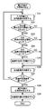
図3はCPU 201が実行する画像補正処理を示すフローチャートである。
[Processing procedure]
FIG. 3 is a flowchart showing an image correction process executed by the
まず、入力画像をRAM 202にロードする(S1)。ロードの形態は限定されるものではないが、例えば、ユーザがキーボード204やマウス205を用いて、外部記憶装置207、記憶媒体またはサーバ装置に保存された処理対象の画像データのファイル名を指定することで、CPU 201にロードを指示してもよいし、あるいは、ユーザがI/F 209にディジタルカメラ(またはスキャナ)を接続し、キーボード204やマウス205を用いてディジタルカメラ(またはスキャナ、実際にはRAM 202にロードされている、それらデバイス用のドライバソフトウェア)に、ディジタルカメラの内部メモリに保存された(またはスキャナで読み取った)画像のデータをRAM 202に転送するよう指示することで、処理対象の画像データをRAM 202にロードしてもよい。
First, the input image is loaded into the RAM 202 (S1). The form of loading is not limited. For example, the user designates the file name of the image data to be processed stored in the
処理対象の画像データは一画素の各チャネルが8ビットで表現されるRGB画像で、かつ、その画像サイズはM×N画素(Mは横方向の画素数、Nは縦方向の画素数)である。また、処理対象の画像データは、R(赤)の画素値のみで構成されるプレーン、G(緑)の画素値のみで構成されるプレーン、および、B(青)の画素値のみで構成されるプレーンの合計三つのプレーンで構成されるが、これに限定されるものではなく、一つのプレーンで構成されるようなカラー画像であってもよい。さらに、処理対象の画像データがJPEG圧縮などされている場合、CPU 201は、画像データを伸長し、各画素がR、G、Bの色成分で表現される画像を生成する。
The image data to be processed is an RGB image in which each channel of one pixel is represented by 8 bits, and the image size is M × N pixels (M is the number of pixels in the horizontal direction and N is the number of pixels in the vertical direction). is there. The image data to be processed is composed of only a plane composed of only R (red) pixel values, a plane composed of only G (green) pixel values, and a B (blue) pixel value. However, the present invention is not limited to this, and a color image composed of one plane may be used. Further, when the image data to be processed is JPEG compressed, the
また、画像データの各チャネルのビット長は8に限るものではなく、その他、例えば各チャネル12、16ビットなどであってもよい。あるいは、画素値の表現を整数に限る必要はなく、実数値であっても構わない。 In addition, the bit length of each channel of the image data is not limited to 8, and may be, for example, 12 or 16 bits for each channel. Alternatively, the representation of the pixel value need not be limited to an integer, and may be a real value.
また、ここではRGB画像を用いて説明するが、他のLCH、YCbCr、L*u*v*、HSV、HSL等他の色空間であっても、前段で、本実施例による処理を行う色空間に色変換することで適切に処理が行えることは言うまでもない。また、その際、画像データの色空間と、本処理を行う色空間と同一である場合には元画像のデータを直接用いて処理を行っても構わない。 In addition, although described here using RGB images, even in other color spaces such as other LCH, YCbCr, L * u * v *, HSV, HSL, etc. Needless to say, appropriate processing can be performed by color conversion to space. In this case, if the color space of the image data is the same as the color space for performing this processing, the processing may be performed using the original image data directly.
次に、RAM 202にロードした入力画像のコントラストを補正する(S2)。このコントラスト補正処理の補正方法は限定されないが、輝度ヒストグラムや入出力関係を表すトーンカーブを用いてコントラストを適切に補正する方法などが例示される。続いて、入力画像のカラーバランスを適切に補正する(S3)。このカラーバランス補正方法は限定されないが、例えばヒストグラムや入出力関係を表すトーンカーブを用いたカラーバランス方法などが挙げられる。
Next, the contrast of the input image loaded in the
次に、所定色領域設定部30の所定色領域の設定に従い、補正後の画像から所定色領域を抽出し(S4)、所定色領域があるか否かを判定する(S5)。所定色領域がない場合、補正後の画像を、例えばプリンタ、外部記憶装置207、または、ネットワーク上のサーバ装置などへ出力する(S7)。また、所定色領域がある場合は、前述した色補正部90による所定色領域の色補正処理(S6)を行った後、補正後の画像を出力する(S7)。
Next, in accordance with the setting of the predetermined color area of the predetermined color
所定色領域の抽出方法は限定されないが、人肌領域であれば顔検出処理により検出した顔の情報を利用する方法や、任意の色相や彩度を指定する方法などが例示される。 Although the extraction method of the predetermined color area is not limited, examples of the human skin area include a method of using face information detected by face detection processing and a method of specifying an arbitrary hue and saturation.
被写体の顔を含む顔領域を用いる場合、上記の顔検出処理を用いて自動的に設定する、あるいは、表示部206に画像を表示してキーボード204やマウス205を用いて対話的にユーザが設定する、の何れであっても良い。本実施例の処理においては顔領域の位置情報があれば以後で説明する処理には充分であり、上記の顔領域設定の際に用いる画像はステップS2、S3による処理前の画像であっても、処理後の画像であっても良い。
When using a face area that includes the face of the subject, it is automatically set using the face detection process described above, or displayed on the
顔検出結果の顔の情報を利用する方法を一例として説明する。画像中の顔領域を検出する処理としては、Yang, et al.「Detecting Faces in Images: A Survey」 IEEE TRANSACTIONS ON PATTERN ANALYSIS AND MACHINE INTELLIGENCE, VOL.24, No.1, January 2002に挙げられているような方式を用いて顔矩形領域を検出すればよい。そして、検出した両目の位置情報を取得し、両目を結ぶ線分とその線分に垂直な線分を辺とする所定の矩形領域を定め、その矩形領域内の画素のRGB値の平均値および共分散行列を求める。このRGB平均値および共分散行列、並びに、検出された顔矩形領域内の各画素のRGB値のマハラノビス距離を計算し、閾値以下の画素を肌色画素とし、その集合を人肌領域とする。 A method of using face information of the face detection result will be described as an example. The process for detecting facial regions in images is listed in Yang, et al. “Detecting Faces in Images: A Survey” IEEE TRANSACTIONS ON PATTERN ANALYSIS AND MACHINE INTELLIGENCE, VOL.24, No.1, January 2002. The face rectangular area may be detected using such a method. Then, the position information of the detected eyes is acquired, a predetermined rectangular area having a line segment connecting the eyes and a line segment perpendicular to the line segment as a side is defined, and an average value of RGB values of pixels in the rectangular area and Find the covariance matrix. The RGB average value and covariance matrix, and the Mahalanobis distance of the RGB value of each pixel in the detected face rectangular area are calculated, pixels below the threshold are defined as skin color pixels, and the set is defined as a human skin area.
さらに、人肌領域の画像上での空間的な連結を調べ、連結した肌色画素をまとめて画像領域に設定する。これは、例えば、肌色画素の連結を調べ、連結した肌色画素には同一のラベルを付与することによって実現される。また、必須ではないが、好ましくは、その際、小領域である画像領域を除去する。これは、例えば小領域判定のための閾値を予め設定しておき、画像領域の画素数が閾値以下の場合、その画像領域を除外するなどの処理を行う。 Further, the spatial connection of the human skin region on the image is examined, and the connected skin color pixels are collectively set in the image region. This is realized, for example, by examining the connection of skin color pixels and assigning the same label to the connected skin color pixels. Further, although it is not essential, it is preferable to remove an image area which is a small area at that time. For example, a threshold value for determining a small area is set in advance, and when the number of pixels in the image area is equal to or smaller than the threshold value, the image area is excluded.
このように、抽出した所定色領域にはラベリングを施す。つまり、所定色領域に属す画素にはラベル番号(例えば、所定色領域外は「0」、j番目の所定色領域は「j」がラベル番号になる)を付与する。なお、ラベル番号は入力画像の画素位置に対応させてRAM 202に格納する。
In this way, the extracted predetermined color area is labeled. That is, a label number (for example, “0” is outside the predetermined color area and “j” is the label number for the jth predetermined color area) is assigned to the pixels belonging to the predetermined color area. The label number is stored in the
● 所定色領域の色補正処理(S6)
図4はCPU 201が実行する所定色領域の色補正処理(S6)を示すフローチャートである。
● Precise color area color correction processing (S6)
FIG. 4 is a flowchart showing the color correction process (S6) of the predetermined color area executed by the
まず、RGB色空間の各値で表現されている入力画像を、LCH色空間(明度L、彩度C、色相H)に変換する(S11)。なお、変換後の色空間は、LCHに限らず、YCbCr、L*u*v*、HSV、HSLなど他の色空間であってもよい。 First, an input image expressed by each value in the RGB color space is converted into an LCH color space (lightness L, saturation C, hue H) (S11). The converted color space is not limited to LCH, and may be other color spaces such as YCbCr, L * u * v *, HSV, and HSL.
次に、反復処理を行うために、抽出した所定色領域の数を変数Nに設定し、カウンタkを零に初期化する(S12)。そして、k番目の所定色領域について代表色を抽出し(S13)、カウンタkをインクリメントし(S14)、ステップS15の判定によりk=NになるまでステップS13、S14の処理を繰り返して、抽出された各所定色領域の代表色を抽出する。 Next, in order to perform an iterative process, the number of extracted predetermined color regions is set to a variable N, and a counter k is initialized to zero (S12). Then, a representative color is extracted for the kth predetermined color area (S13), the counter k is incremented (S14), and the process of steps S13 and S14 is repeated until k = N by the determination of step S15. The representative color of each predetermined color area is extracted.
図5は代表色の抽出処理(S13)を示すフローチャートである。 FIG. 5 is a flowchart showing the representative color extraction process (S13).
まず、入力画像から注目画素を取得し(S41)、注目画素に対するラベル番号を参照して、注目画素がk番目の所定色領域の画素か否かを判定し(S42)、注目画素がk番目の所定色領域の画素であれば、注目画素の明度Lが閾値Lth以上か否かを判定する(S43)。例えば、人肌領域の場合、抽出した領域に目、眉、髭または陰影が含まれると代表色が適切に得られない場合がある。そこでステップS42およびS43の判定により、補正対象の肌色よりも明度が低いと考えられる陰影、目、眉または髭といった領域を構成する画素を除外する。 First, the target pixel is acquired from the input image (S41), and it is determined whether or not the target pixel is a pixel in the kth predetermined color region with reference to the label number for the target pixel (S42). If it is a pixel of the predetermined color area, it is determined whether or not the lightness L of the target pixel is equal to or greater than the threshold Lth (S43). For example, in the case of a human skin region, if the extracted region includes eyes, eyebrows, eyelids, or shadows, a representative color may not be obtained appropriately. Therefore, the determination of steps S42 and S43 excludes pixels that constitute areas such as shadows, eyes, eyebrows, and eyelids that are considered to have a lightness lower than the skin color to be corrected.
次に、ステップS42およびS43の条件を満たす注目画素について、その画素の彩度Cおよび色相Hを集計する(S44)。この集計方法は、代表色として何を採用するかによって変わるが、例えば代表色を画素の平均値とする場合は、彩度Cおよび色相Hを単純に加算し、加算値を集計した画素数をカウントする。 Next, for the pixel of interest that satisfies the conditions of steps S42 and S43, the saturation C and hue H of the pixel are totaled (S44). This aggregation method varies depending on what is adopted as the representative color.For example, when the representative color is the average value of the pixels, the saturation C and the hue H are simply added, and the number of pixels obtained by adding the addition values is calculated. Count.
次に、注目画素を移動し(S45)、入力画像の全画素を調べたか否かを判定し(S46)、全画素を調べるまでステップS41からS45の処理を繰り返す。そして、入力画像の全画素について調査が終了すると、k番目の所定色領域の代表色を設定する(S47)。代表色を所定色領域内の画素の彩度Cおよび色相Hの平均値とする場合、ステップS44の加算結果をカウント値で除算した値CrおよびHrを代表色に設定する。 Next, the target pixel is moved (S45), it is determined whether or not all the pixels of the input image have been examined (S46), and the processing from step S41 to S45 is repeated until all the pixels are examined. When the survey is completed for all pixels of the input image, the representative color of the kth predetermined color area is set (S47). When the representative color is the average value of the saturation C and the hue H of the pixels in the predetermined color area, values Cr and Hr obtained by dividing the addition result in step S44 by the count value are set as the representative colors.
上記では、ステップS13の反復処理により、N個の所定色領域の代表色を抽出する例を説明したが、図5に示すステップS42の処理に、注目画素がどの所定色領域に属すかの判定を加え、ステップS44で画素が属す所定色領域ごとに彩度Cおよび色相Hを集計すれば、ステップS47でN個の所定色領域の代表色を一度に設定することができる。この場合、上記の反復処理は不要になる。 In the above, the example in which the representative colors of the N predetermined color areas are extracted by the iterative process of step S13 has been described. However, in the process of step S42 shown in FIG. 5, the predetermined color area to which the target pixel belongs is determined. In step S44, if the saturation C and the hue H are counted for each predetermined color region to which the pixel belongs, in step S47, the representative colors of N predetermined color regions can be set at a time. In this case, the above iterative process becomes unnecessary.
次に、図4に示す処理に戻り、各所定色領域の重要度を判定する(S16)。例えば、所定色領域の面積(当該領域に属する画素の数)、所定色領域の、入力画像上の位置、および、所定色領域の代表輝度に応じて重要度を算出する。以下では、k番目(0<k<N)の所定色領域の、面積をS(k)、重要度をI(k)、面積による重要度をIs(k)、位置による重要度をIp(k)、輝度による重要度をIb(k)と表記する。 Next, returning to the processing shown in FIG. 4, the importance of each predetermined color area is determined (S16). For example, the importance is calculated according to the area of the predetermined color region (the number of pixels belonging to the region), the position of the predetermined color region on the input image, and the representative luminance of the predetermined color region. Below, the area of the kth (0 <k <N) predetermined color area is S (k), importance is I (k), importance by area is Is (k), and importance by position is Ip ( k), the importance based on luminance is expressed as Ib (k).
まず、面積による重要度Is(k)を算出する。所定色領域の面積S(k)は、当該領域を表す情報から算出する。当該領域の形状が矩形、円形、楕円形、三角形などの比較的単純な形状であれば、その面積の算出に必要な数値(例えば、矩形ならば縦横の画素数、円形ならば半径の画素数など)を調べ、面積を算出すればよい。しかし、一般に、肌色領域などの所定色領域は不定形である可能性が高く、その場合、所定色領域の色を示す画素(例えば肌色画素)の数を計数する。これは、ステップS4における所定色領域のラベリングあるいはステップS13の代表色の抽出処理で行えばよい。 First, the importance Is (k) based on the area is calculated. The area S (k) of the predetermined color area is calculated from information representing the area. If the shape of the area is a relatively simple shape such as a rectangle, circle, ellipse, triangle, etc., the number required to calculate the area (for example, the number of vertical and horizontal pixels for a rectangle, the number of radius pixels for a circle) Etc.) and the area may be calculated. However, in general, there is a high possibility that a predetermined color area such as a skin color area is indefinite, and in this case, the number of pixels (for example, skin color pixels) indicating the color of the predetermined color area is counted. This may be performed by labeling a predetermined color area in step S4 or representative color extraction processing in step S13.
そして、面積S(0)〜S(N-1)から、面積による重要度Is(0)〜Is(N-1)を算出する。なお、各所定色領域の面積を、所定色領域の面積の最大値で正規化した値を用いる。
Is(k) = S(k)/Smax …(1)
ここで、SmaxはS(0)〜S(N-1)の最大値
Then, the importance levels Is (0) to Is (N-1) based on the areas are calculated from the areas S (0) to S (N-1). A value obtained by normalizing the area of each predetermined color region with the maximum value of the area of the predetermined color region is used.
Is (k) = S (k) / Smax… (1)
Where Smax is the maximum value of S (0) to S (N-1)
式(1)の重要度算出式は一例であって、例えば、所定色領域の総面積を用いて正規化するような変形は容易である。勿論、他の算出式でもよい。 The importance calculation formula of the formula (1) is an example, and for example, it is easy to modify the normalization using the total area of the predetermined color region. Of course, other calculation formulas may be used.
次に、所定色領域の位置による重要度Ip(k)を算出する。まず、所定色領域の重心を算出し、重心の座標値から位置による重要度Ip(k)を算出する。 Next, the importance level Ip (k) based on the position of the predetermined color region is calculated. First, the center of gravity of the predetermined color region is calculated, and the importance Ip (k) depending on the position is calculated from the coordinate value of the center of gravity.
図6は重心位置による重要度を説明する図である。図6において、画像601の中央部602は比較的主要な被写体(または被写体の中心)が配置されると想定される範囲である。そして、水平位置による重要度Iphおよび垂直位置による重要度Ipvを定義し、中央部602における重要度IphおよびIpvを「1」とし、画像601の周辺に向かって重要度IphおよびIpvを低下させ、画像端で重要度IphおよびIpvを「0」にする。なお、すなわち、重心の水平方向の正規化座標がh1〜h2の場合は重要度Iph=1になり、重心の垂直方向の正規化座標がv1〜v2の場合は重要度Ipv=1になり、それ以外の場合、重要度は0以上1未満の値になる。そして、位置による重要度Ip(k)は式(2)によって算出する。
Ip(k) = Iph(k)×Ipv(k) …(2)
FIG. 6 is a diagram for explaining the importance according to the position of the center of gravity. In FIG. 6, a
Ip (k) = Iph (k) x Ipv (k) (2)
勿論、Ip(k)をIph(k)とIpv(k)の平均値、最大値、最小値としてもよい。また、図6に示す中央部602は、矩形に限らず、円や楕円などもよい。 Of course, Ip (k) may be the average value, maximum value, and minimum value of Iph (k) and Ipv (k). 6 is not limited to a rectangle, but may be a circle or an ellipse.
次に、所定色領域の輝度による重要度Ib(k)を算出する。まず、所定色領域の代表輝度を決定するが、代表輝度はステップS13の代表色の抽出(彩度Cおよび色相Hの集計)と同様に、輝度Lについて集計を行えばよい。そして、輝度Lの集計結果から平均輝度(あるいは重み付け平均値、中央値、最大値、最小値、最頻値など)を算出して、それを当該領域の代表輝度にする。勿論、輝度をヒストグラムとして集計し、ヒストグラムを解析して代表輝度を算出してもよい。このように、代表輝度の決定に必要な、輝度Lの集計は、ステップS16で行う必要はなく、ステップS13の代表色の抽出中にあわせて行うようにしてもよい。 Next, the importance level Ib (k) based on the luminance of the predetermined color region is calculated. First, the representative luminance of the predetermined color region is determined. The representative luminance may be aggregated with respect to the luminance L in the same manner as the representative color extraction (summation of saturation C and hue H) in step S13. Then, the average luminance (or weighted average value, median value, maximum value, minimum value, mode value, etc.) is calculated from the result of aggregation of the luminance L, and is used as the representative luminance of the area. Of course, the luminance may be aggregated as a histogram, and the representative luminance may be calculated by analyzing the histogram. As described above, the aggregation of the luminance L necessary for determining the representative luminance is not necessarily performed in step S16, and may be performed in accordance with the extraction of the representative color in step S13.
図7は代表輝度と重要度Ib(k)の関係を示す図である。例えば、肌色領域における肌色の適正な明るさは、一般に、画像中の最大輝度の60〜90%程度であるといわれる。図7に示すThMinおよびThMaxは、所定色領域の色の適正な明るさの最小値および最大値を表す。図7に示すような明るさと重要度Ib(k)の対応関係を予め定めておき、各所定色領域の代表輝度から輝度による重要度Ib(k)を算出する。 FIG. 7 is a diagram showing the relationship between representative luminance and importance level Ib (k). For example, the appropriate brightness of the skin color in the skin color region is generally said to be about 60 to 90% of the maximum luminance in the image. ThMin and ThMax shown in FIG. 7 represent minimum and maximum values of appropriate brightness of colors in a predetermined color region. A correspondence relationship between brightness and importance Ib (k) as shown in FIG. 7 is determined in advance, and importance Ib (k) based on luminance is calculated from the representative luminance of each predetermined color area.
勿論、図7に示す輝度と重要度の関係は一例であって、この他の対応関係でも構わない。 Of course, the relationship between luminance and importance shown in FIG. 7 is an example, and other correspondence relationships may be used.
このようにして算出した、面積による重要度Is(k)、位置による重要度Ip(k)、輝度による重要度Ib(k)から各所定色領域の重要度I(k)を決定する。
I(k) = Is(k)×Ip(k)×Ib(k) …(3)
The importance level I (k) of each predetermined color region is determined from the importance level Is (k) based on the area, the importance level Ip (k) based on the position, and the importance level Ib (k) based on the brightness.
I (k) = Is (k) × Ip (k) × Ib (k) (3)
勿論、重要度I(k)の計算は、三つの重要度の掛け算に限らず、平均値、重み付け平均値、最大値、最小値、中央値などでもよく、本実施例が意図する所定色領域の面積、位置および輝度を考慮して重要度を求める方法であればよい。また、所定色領域の面積、位置および輝度による重要度のほかに、他の領域に対する重要度を設けて、それを加味して所定色領域の重要度を決定してもよい。また、面積、位置および輝度による重要度すべてが必須というわけではなく、これらのうちの何れかを用いない変形も可能である。つまり、画像領域の重要度を評価する手段を設け、各画像領域を評価して、所定色領域の重要度を決定すればよい。 Of course, the calculation of the importance level I (k) is not limited to the multiplication of the three importance levels, and may be an average value, a weighted average value, a maximum value, a minimum value, a median value, etc. Any method may be used as long as the degree of importance is calculated in consideration of the area, position, and luminance. Further, in addition to the importance based on the area, position, and luminance of the predetermined color area, importance on other areas may be provided, and the importance of the predetermined color area may be determined in consideration of the importance. In addition, not all importance based on area, position, and luminance is essential, and modifications that do not use any of these are possible. That is, a means for evaluating the importance of the image area may be provided, and each image area may be evaluated to determine the importance of the predetermined color area.
次に、各所定色領域の代表色から全体として一つの代表色を決定する(S17)。以下では、k番目の領域の代表色を(Cr(k), Hr(k))、ステップS17で決定する、全体として一つの代表色を(Cr, Hr)とする。 Next, one representative color is determined as a whole from the representative colors of each predetermined color region (S17). In the following, the representative color of the kth region is (Cr (k), Hr (k)), and one representative color as a whole is (Cr, Hr) determined in step S17.
まず、各代表色をa*b*データに変換するが、これは、式(4)により、極座標系(C-H座標系)のCHデータををxy座標系に変換することに相当する。
a*(k) = Cr(k)×cos(Hr(k))
b*(k) = Cr(k)×sin(Hr(k)) …(4)
First, each representative color is converted into a * b * data, which corresponds to converting the CH data in the polar coordinate system (CH coordinate system) into the xy coordinate system according to Equation (4).
a * (k) = Cr (k) x cos (Hr (k))
b * (k) = Cr (k) × sin (Hr (k))… (4)
そして、(a*(k), b*(k))を各所定色領域の重要度I(k)で重み付け平均する。
ar* = {Σka*(k)×I(k)}/ΣkI(k)
br* = {Σkb*(k)×I(k)}/ΣkI(k) …(5)
Then, (a * (k), b * (k)) is weighted and averaged with the importance I (k) of each predetermined color area.
ar * = {Σ k a * (k) × I (k)} / Σ k I (k)
br * = {Σ k b * (k) × I (k)} / Σ k I (k)… (5)
そして、(ar*, br*)をC-H座標系に戻して(Cr, Hr)を求める。
Cr = √(ar*2 + br*2)
Hr = tana-1(br*/ar*) …(6)
Then, (ar *, br *) is returned to the CH coordinate system to obtain (Cr, Hr).
Cr = √ (ar * 2 + br * 2 )
Hr = tana -1 (br * / ar *)… (6)
なお、所定色領域が人肌領域など、ある程度色相が揃っている場合は、単に(Cr(k), Hr(k))を重み付け平均して代表色(Cr, Hr)を算出してもよい。あるいは、各所定色領域のうち最大の重要度をもつ領域の代表色を全体の代表色にしてもよい。 When the predetermined color area is a certain amount of hue, such as a human skin area, the representative color (Cr, Hr) may be calculated simply by weighted average of (Cr (k), Hr (k)). . Alternatively, the representative color of the area having the greatest importance among the predetermined color areas may be the entire representative color.
次に、目標色メモリ50から目標色のデータを取得し(S18)、代表色と目標色の差から色補正における補正量を制御する補正係数を設定する(S19)。色補正における補正量は色相Hと彩度Cごとに定めるため、補正係数も色相Hと彩度Cごとに色相補性係数Phおよび彩度補正係数Pcとして設定する。 Next, target color data is acquired from the target color memory 50 (S18), and a correction coefficient for controlling a correction amount in color correction is set from the difference between the representative color and the target color (S19). Since the correction amount in the color correction is determined for each hue H and saturation C, the correction coefficient is also set as the color complementation coefficient Ph and saturation correction coefficient Pc for each hue H and saturation C.
色相補正係数Phは、例えば式(7)に示すように、補正目標色の色相Htと代表色の色相Hrの差が大きくなると、減少するように設定する。
Ph(Hdist) = K1・exp(-Hdist 2/t1) …(7)
ここで、K1、t1は定数
Hdist = |Ht - Hr|
The hue correction coefficient Ph is set so as to decrease as the difference between the hue Ht of the correction target color and the hue Hr of the representative color increases, for example, as shown in Equation (7).
Ph (H dist ) = K1 ・ exp (-H dist 2 / t1)… (7)
Where K1 and t1 are constants
H dist = | Ht-Hr |
つまり、補正対象の色の代表色の色相Hrが目標色の色相Htに近いほど、代表色の色相Hrを目標色の色相Htにより近付けるような補正を行い、代表色の色相Hrが目標色の色相Htから大きく離れている場合は、あまり補正を行わないように補正係数Phを設定する。このように補正係数を設定する理由として、補正対象とする色の代表色の色相Hr(k)が目標色の色相Htから大きく離れている場合、代表色を目標色により近付けるような補正を行うと、入力画像全体のカラーバランスが崩れてしまうからである。 In other words, the closer the hue Hr of the representative color of the color to be corrected is to the target hue Ht, the closer the hue Hr of the representative color is to the hue Ht of the target color, and the hue Hr of the representative color is the target color. If it is far from the hue Ht, the correction coefficient Ph is set so as not to make much correction. As a reason for setting the correction coefficient in this way, when the hue Hr (k) of the representative color of the color to be corrected is far from the hue Ht of the target color, correction is performed so that the representative color is closer to the target color. This is because the color balance of the entire input image is lost.
同様に、彩度補正係数Pcは、目標色の彩度Ctと代表色の彩度Crの差が大きくなると、減少するように設定する。つまり、補正対象とする色の代表色の彩度Crが目標色の彩度Ctに近いほど代表色の彩度Crを目標色の彩度Ctにより近付けるような補正を行い、代表色の彩度Crが目標色の彩度Ctから大きく離れている場合は、あまり補正を行わないように補正係数Pcを設定する。ただし、彩度補正係数Pcは、彩度を下げるように補正する場合と、彩度を上げるように補正をする場合とで設定方法が異なる。これは、彩度を下げる場合、補正により画像の印象が地味になる現象を防ぐように補正係数を設定する方が望ましく、逆に、彩度を上げる場合は、補正対象とする色の代表色の彩度Crが、目標色の彩度Ctから離れていても、目標色の彩度Ctに近付けるような補正を行う方が画像の印象がよくなる効果が期待できるからである。このような彩度補正係数Pcの設定方法として、例えば、彩度を上げる場合は式(8)、彩度を下げる場合は式(9)を用いる。
Ct < Crの場合 Pc(Cdist) = -a1・Cdist 2 + b1 …(8)
Ct ≧ Crの場合 Pc(Cdist) = K2・exp(-Cdist 2/t2) …(9)
ここで、a1、b1、K2、t2は定数
Cdist = |Ct - Cr|
Similarly, the saturation correction coefficient Pc is set to decrease as the difference between the saturation Ct of the target color and the saturation Cr of the representative color increases. That is, as the saturation Cr of the representative color of the color to be corrected is closer to the saturation Ct of the target color, correction is performed so that the saturation Cr of the representative color is closer to the saturation Ct of the target color. When Cr is far away from the saturation Ct of the target color, the correction coefficient Pc is set so as not to make much correction. However, the method of setting the saturation correction coefficient Pc differs depending on whether the correction is performed so as to decrease the saturation or the correction is performed so as to increase the saturation. This is because when reducing saturation, it is desirable to set a correction coefficient so as to prevent the phenomenon that the impression of the image becomes plain due to correction. Conversely, when increasing saturation, the representative color of the color to be corrected This is because even if the saturation Cr of the image is far from the saturation Ct of the target color, an effect of improving the impression of the image can be expected by performing correction so as to approach the saturation Ct of the target color. As a method for setting such a saturation correction coefficient Pc, for example, Expression (8) is used to increase the saturation, and Expression (9) is used to decrease the saturation.
When Ct <Cr Pc (C dist ) = -a1 ・ C dist 2 + b1… (8)
When Ct ≥ Cr Pc (C dist ) = K2 ・ exp (-C dist 2 / t2)… (9)
Where a1, b1, K2, and t2 are constants
C dist = | Ct-Cr |
図8は式(8)(9)を示すグラフで、横軸は目標色の彩度Ctと代表色の彩度Crの差、縦軸は彩度補正係数Pcを示す。図8に示すように、彩度を下げる補正における彩度補正係数(実線)と、彩度を上げる補正における彩度補正係数(点線)の値は、彩度の差が等しくても、図にC1で示すように異なり、彩度を下げる補正における彩度補正係数(実線)がより小さいことがわかる。これは、彩度を下げるように補正する場合、彩度を上げるように補正する場合に比べて補正量が小さくなることを示す。 FIG. 8 is a graph showing Expressions (8) and (9), where the horizontal axis represents the difference between the saturation Ct of the target color and the saturation Cr of the representative color, and the vertical axis represents the saturation correction coefficient Pc. As shown in FIG. 8, the saturation correction coefficient (solid line) in the saturation reduction correction and the saturation correction coefficient (dotted line) in the saturation enhancement correction are shown in the figure even if the saturation difference is equal. As shown by C1, it can be seen that the saturation correction coefficient (solid line) in the correction for decreasing the saturation is smaller. This indicates that the correction amount is smaller when the saturation is corrected to be lower than when the saturation is corrected to be increased.
次に、補正対象の色領域を設定する(S20)。図9は補正対象の色領域の設定処理(S19)を示すフローチャートである。 Next, a color area to be corrected is set (S20). FIG. 9 is a flowchart showing the setting process (S19) of the color area to be corrected.
色領域の設定では、所定色領域内の画素の色相に注目し、補正対象とする代表色を含む色領域を設定し、その領域を色補正の対象領域にする。これは、入力画像の全領域に対して、例えば人肌を好ましい肌色にする補正を行えば、元々好ましい色であった画像中の他の領域の色が不自然になってしまう問題を防ぐためである。 In setting the color area, paying attention to the hue of the pixels in the predetermined color area, a color area including a representative color to be corrected is set, and the area is set as a color correction target area. This is to prevent the problem that the colors of other regions in the image that are originally preferable colors become unnatural if correction is made to a preferable skin color for all regions of the input image, for example. It is.
まず、入力画像から注目画素を取得し(S31)、注目画素が所定色領域の画素か否かを判定し(S32)、注目画素が所定色領域の画素であれば、注目画素の明度Ltが閾値Lth以上か否かを判定する(S33)。ステップS32およびS33の判定は、代表色の抽出と同様に、例えば、人肌領域の場合、抽出した領域に含まれる目、眉、髭または陰影といった領域を構成する画素を除外するためである。 First, the target pixel is acquired from the input image (S31), it is determined whether the target pixel is a pixel in the predetermined color area (S32), and if the target pixel is a pixel in the predetermined color area, the brightness Lt of the target pixel is It is determined whether or not the threshold value Lth is exceeded (S33). For example, in the case of a human skin region, the determinations in steps S32 and S33 are for excluding the pixels constituting the region such as eyes, eyebrows, eyelids, or shadows included in the extracted region.
次に、ステップS32およびS33の条件を満たす画素について、その画素の彩度Cが無彩色の彩度閾値Cth以上であるか否かを判定する(S34)。注目画素の彩度Cが閾値Cth未満であるということは、注目画素が無彩色に限りなく近いことを意味する。ここで無彩色画素を除く理由は、無彩色領域においてはRGB値の僅かな差で色相が大きく変わり、所定色領域に対応する色相領域を高精度に決めることができなくなる問題を防ぐためである。 Next, for a pixel that satisfies the conditions of steps S32 and S33, it is determined whether the saturation C of the pixel is equal to or greater than the saturation threshold Cth of the achromatic color (S34). That the saturation C of the pixel of interest is less than the threshold Cth means that the pixel of interest is as close as possible to an achromatic color. Here, the reason for excluding the achromatic color pixel is to prevent a problem in which the hue changes greatly due to a slight difference in RGB values in the achromatic color area, and the hue area corresponding to the predetermined color area cannot be determined with high accuracy. .
次に、ステップS32からS34の条件を満たす注目画素について、その画素の色相Hを集計する(S35)。この集計方法は、所定色領域を示す特定色相として何を採用するかによって変わるが、例えば、ステップS32からS34の条件を満たす画素の色相分布を解析し、最大色相Hmaxおよび最小色相Hminによって補正対象の色領域を示す方法が例示される。 Next, for the target pixel that satisfies the conditions of steps S32 to S34, the hue H of the pixel is totaled (S35). This aggregation method varies depending on what is adopted as the specific hue indicating the predetermined color area.For example, the hue distribution of the pixels satisfying the conditions of steps S32 to S34 is analyzed, and the correction target is determined by the maximum hue Hmax and the minimum hue Hmin. A method for indicating the color region of is illustrated.
次に、注目画素を移動し(S36)、入力画像の全画素を調べたか否かを判定し(S37)、全画素を調べるまでステップS31からS36の処理を繰り返す。そして、入力画像の全画素について調査が終了すると、補正対象の色領域を設定する(S38)。前述した最大色相Hmaxおよび最小色相Hminによって補正対象の色領域を示す場合、例えば式(10)に示すように、集計結果である最大色相および最小色相を用いて、代表色相Hrとの差から補正対象とする色領域を設定する。
ΔH = max(|Hmax - Hr|, |Hmin - Hr|) …(10)
ここで、関数max()は括弧の中で最大のものを選択する関数
Next, the pixel of interest is moved (S36), it is determined whether or not all the pixels of the input image have been examined (S37), and the processing from step S31 to S36 is repeated until all the pixels are examined. Then, when the survey for all the pixels of the input image is completed, a color area to be corrected is set (S38). When the color area to be corrected is indicated by the maximum hue Hmax and the minimum hue Hmin described above, for example, as shown in Equation (10), correction is performed from the difference from the representative hue Hr using the maximum hue and the minimum hue as the total result. Set the target color area.
ΔH = max (| Hmax-Hr |, | Hmin-Hr |) (10)
Here, the function max () is a function that selects the largest one among the parentheses.
つまり、補正対象の色領域は、図3に示すステップS4において抽出される所定色領域を包含するような色相範囲として設定される。 That is, the color area to be corrected is set as a hue range including the predetermined color area extracted in step S4 shown in FIG.
なお、ステップS32からS34の条件を満たす画素群の色相分布から、最大色相Hmaxおよび最小色相Hminを自動的に導出する例を示した。しかし、補正対象の色領域を示す特定色相の設定方法はこれに限定されるものではない。入力画像の状態によっては、例えば、ユーザが任意の色相領域をマニュアル設定する、あるいは、目標色メモリ50に予め登録された色相領域を選択するなどした方が好ましい場合もある。ただし、この場合でも補正対象の色領域は、ステップS4において抽出される所定色領域を包含するような、色相範囲として設定することが望ましく、ユーザの設定または選択に対して、所定色領域の包含が不充分の場合に警告を発するなどの処置をとることが望ましい。
An example has been shown in which the maximum hue Hmax and the minimum hue Hmin are automatically derived from the hue distribution of the pixel group that satisfies the conditions of steps S32 to S34. However, the method for setting the specific hue indicating the color area to be corrected is not limited to this. Depending on the state of the input image, for example, it may be preferable that the user manually sets an arbitrary hue area or selects a hue area registered in advance in the
次に、設定した色領域に対して、後述する色補正において使用する色領域の重みを色相範囲と彩度範囲ごとに設定する(S39)。 Next, for the set color area, the weight of the color area used in the color correction described later is set for each hue range and saturation range (S39).
まず、色相の重みWhは代表色で「1」、補正対象の色領域外では「0」になるように、式(11)のように定める。これは、後述する色補間を行う場合に、補正対象の色相領域内外で色の連続性が破綻するのを防ぐためである。
HがHr±ΔHの範囲内 Wh = |H - Hr|/ΔH
Hが上記範囲外 Wh = 0 …(11)
First, the hue weight Wh is determined as shown in Expression (11) so that it is “1” for the representative color and “0” outside the color region to be corrected. This is to prevent the color continuity from breaking inside and outside the hue area to be corrected when performing color interpolation, which will be described later.
H is within the range of Hr ± ΔH Wh = | H-Hr | / ΔH
H is outside the above range Wh = 0… (11)
ただし、重みの設定方法は、式(11)に示す方法に限らず、例えば、補正対象の色領域を示す色相範囲、代表色、および、任意の定数を用いて非線形に変化する設定方法などが例示される。 However, the method of setting the weight is not limited to the method shown in Equation (11), and for example, there is a setting method that changes non-linearly using a hue range indicating the color region to be corrected, a representative color, and an arbitrary constant. Illustrated.
また、彩度の重みWcは、目標色の彩度Crおよび無彩色の彩度閾値Cthから、式(12)のように定める。
C < Cthの場合 Wc = 0
Cth ≦ C ≦ Crの場合 Wc = (C - Cth)/(Cr - Cth) …(12)
C > Crの場合 Wc = 1
Further, the saturation weight Wc is determined as shown in Expression (12) from the saturation Cr of the target color and the saturation threshold Cth of the achromatic color.
If C <Cth Wc = 0
When Cth ≤ C ≤ Cr Wc = (C-Cth) / (Cr-Cth)… (12)
When C> Cr Wc = 1
ただし、重みの設定方法は、式(12)に示す方法に限らず、例えば、所定色領域を包含する彩度範囲ΔCを色相領域の設定方法と同様な方法で求め、彩度の重みWcを設定する方法なども挙げられる。 However, the weight setting method is not limited to the method shown in Expression (12) .For example, the saturation range ΔC including the predetermined color area is obtained by the same method as the hue area setting method, and the saturation weight Wc is calculated. The setting method etc. are also mentioned.
このように補正対象とする色領域を重み付ける理由は、後述する色補正を行う場合に、補正対象の色相領域内外で色の連続性が破綻することを防ぐためである。 The reason for weighting the color area to be corrected in this way is to prevent the color continuity from breaking inside and outside the hue area to be corrected when color correction described later is performed.
次に、図4に示す処理に戻り、入力画像における所定色領域の位置情報から、色補正に用いる画像領域の重みを設定する(S21)。後述する色補正においては、ステップS20で設定した、所定色領域の重みを利用して所定色に対してのみ色補正を行うことで、元々好ましい色であった画像中の他の領域の色が不自然になる現象を回避する。しかし、補正対象の色領域のみを設定した場合、例えば入力画像において、ステップS20において設定した色相範囲ΔHに含まれる、所定色領域外の画素が存在すると、同画素も色補正の対象になる。そこで、このような問題を解決する方法として、ステップS21で設定する画像領域の重みを利用する。 Next, returning to the processing shown in FIG. 4, the weight of the image area used for color correction is set from the position information of the predetermined color area in the input image (S21). In color correction to be described later, by performing color correction only on a predetermined color using the weight of the predetermined color area set in step S20, the colors of other areas in the image that were originally preferable colors can be obtained. Avoid unnatural phenomena. However, when only the color area to be corrected is set, for example, in the input image, if a pixel outside the predetermined color area included in the hue range ΔH set in step S20 exists, the pixel is also subjected to color correction. Therefore, as a method for solving such a problem, the weight of the image area set in step S21 is used.
画像領域の重みは、所定色領域内の画素が色補正の対象となり、所定色領域外の画素が色補正の非対象になるように0以上1以下の値Wp(x, y)を設定する。ただし、0≦x≦M-1、0≦y≦N-1である。また、色補正により所定色領域の境界付近で色の連続性が破綻するのを防ぐように、画像領域の重みを設定することが望ましい。 The weight of the image area is set to a value Wp (x, y) between 0 and 1 so that pixels in the predetermined color area are subject to color correction and pixels outside the predetermined color area are not subject to color correction. . However, 0 ≦ x ≦ M−1 and 0 ≦ y ≦ N−1. In addition, it is desirable to set the weight of the image area so as to prevent the color continuity from breaking near the boundary of the predetermined color area due to the color correction.
画像領域の重みの設定方法は、限定されないが、所定色領域の重心を求め、重心と各画素の距離に応じた重みを付ける方法などが例示される。この設定方法を用いると、後述する色補正において、所定色領域の境界付近の画素に対する補正量は、所定色領域の中心付近の画素に比べて小さくなり、所定色領域の境界付近で色の連続性が破綻するのを防ぐことができる。また、所定色領域にガウシアンフィルタなどによりローパス処理を施し、所定色領域の境界付近をぼかすことで、所定色領域内外の色の連続性の破綻を和らげる方法なども挙げられる。 The method of setting the weight of the image area is not limited, and examples include a method of obtaining a centroid of a predetermined color area and assigning a weight according to the distance between the centroid and each pixel. When this setting method is used, in the color correction described later, the correction amount for pixels near the boundary of the predetermined color region is smaller than the pixels near the center of the predetermined color region, and the color continuity is near the boundary of the predetermined color region. Sexual breakdown can be prevented. In addition, there is a method in which a low-pass process is performed on a predetermined color area using a Gaussian filter or the like, and the vicinity of the boundary of the predetermined color area is blurred, thereby reducing the continuity of colors inside and outside the predetermined color area.
次に、所定色領域の代表色、代表色を含む補正処理の対象の色領域、および、画像領域の重みを利用して、入力画像中の補正対象の画素の色相および彩度を補正し(S22およびS23)、補正後の画像をRGB色空間に変換し(S24)、その後、図3に示すステップS7で補正後の画像を出力する。 Next, the hue and saturation of the pixel to be corrected in the input image are corrected using the representative color of the predetermined color region, the color region to be corrected including the representative color, and the weight of the image region ( S22 and S23), the corrected image is converted into the RGB color space (S24), and then the corrected image is output in step S7 shown in FIG.
ステップS22の色相補正は、代表色における色相補正量Dhを算出する。色相補正量Dhは、目標色の色相Htと代表色の色相Hrの差、並びに、色相補正係数Phの積として表される(式(13)参照)。そして、色相補正量Dhに、色相領域の重みWh、彩度領域の重みWcおよび画像領域重みWpを掛けた分、入力画像の画素の色相Hを補正する(式(13)参照)。
H' = H + W・Dh
Dh = Ph(Ht - Hr) …(13)
W = Wh・Wc・Wp
ここで、Hは色補正前の画素の色相
H'は色補正後の画素の色相
In the hue correction in step S22, the hue correction amount Dh for the representative color is calculated. The hue correction amount Dh is expressed as a product of the difference between the hue Ht of the target color and the hue Hr of the representative color, and the hue correction coefficient Ph (see Expression (13)). Then, the hue H of the input image pixel is corrected by multiplying the hue correction amount Dh by the hue region weight Wh, the saturation region weight Wc, and the image region weight Wp (see Expression (13)).
H '= H + W ・ Dh
Dh = Ph (Ht-Hr)… (13)
W = Wh ・ Wc ・ Wp
Where H is the hue of the pixel before color correction
H 'is the hue of the pixel after color correction
同様に、ステップS23の彩度補正は、彩度補正係数Pcから代表色における彩度補正率Kcを算出し、彩度補正率Kcに色相領域の重みWh、彩度領域の重みWc、並びに、画像領域の重みWpを色補正前の画素の彩度Cに掛けた分、入力画像内の画素の彩度Cを補正する(式(14)参照)。彩度補正率Kcは、式(14)に示すように、目標色の彩度Ct、代表色の彩度Crの差、および、補正彩度係数Pcによって表される。
C' = C(W・Kc + 1)
Kc = Pc(Ct - Cr)/Cr (Ct≠0) …(14)
W = Wh・Wc・Wp
ここで、Cは色補正前の画素の彩度
C'は色補正後の画素の彩度
Similarly, the saturation correction in step S23 calculates the saturation correction rate Kc for the representative color from the saturation correction coefficient Pc, and the hue correction area Kc includes the hue area weight Wh, the saturation area weight Wc, and The saturation C of the pixel in the input image is corrected by multiplying the image region weight Wp by the saturation C of the pixel before color correction (see Expression (14)). The saturation correction rate Kc is represented by the saturation Ct of the target color, the difference of the saturation Cr of the representative color, and the corrected saturation coefficient Pc, as shown in Expression (14).
C '= C (W ・ Kc + 1)
Kc = Pc (Ct-Cr) / Cr (Ct ≠ 0)… (14)
W = Wh ・ Wc ・ Wp
Where C is the saturation of the pixel before color correction
C 'is the saturation of the pixel after color correction
[変形例]
上記の実施例では、ディジタルカメラで撮影した画像をコンピュータで処理する場合を中心について説明したが、写真などをスキャナで読み取った画像の処理にも適用することができる。また、本実施例の機能は、コンピュータだけでなく、ディジタルカメラ、スキャナ、ディスプレイ、プリンタなどのカラー画像機器本体に組み込むこともできる。
[Modification]
In the above-described embodiment, the case where an image captured by a digital camera is processed by a computer has been mainly described. However, the present invention can also be applied to processing of an image obtained by reading a photograph or the like by a scanner. The function of this embodiment can be incorporated not only in a computer but also in a color image apparatus main body such as a digital camera, a scanner, a display, and a printer.
また、上記の実施例では、所定色の領域ごとの代表色を重要度に応じて合成し、入力画像に対する代表色を求め、この代表色に応じて色補正条件を求めたが、他の方法を用いて色補正条件を求めても構わない。例えば、各所定色の領域ごとに色補正条件を求め、求められた色補正条件を重要度に応じて合成して、入力画像に対する色補正条件を求めても構わない。 In the above embodiment, the representative colors for each predetermined color area are synthesized according to the importance, the representative color for the input image is obtained, and the color correction condition is obtained according to the representative color. The color correction condition may be obtained using For example, the color correction condition may be obtained for each predetermined color area, and the obtained color correction condition may be synthesized according to the importance to obtain the color correction condition for the input image.
[他の実施例]
なお、本発明は、複数の機器(例えばホストコンピュータ、インタフェイス機器、リーダ、プリンタなど)から構成されるシステムに適用しても、一つの機器からなる装置(例えば、複写機、ファクシミリ装置など)に適用してもよい。
[Other embodiments]
Note that the present invention can be applied to a system including a plurality of devices (for example, a host computer, an interface device, a reader, and a printer), and a device (for example, a copying machine and a facsimile device) including a single device. You may apply to.
また、本発明の目的は、前述した実施例の機能を実現するソフトウェアのプログラムコードを記録した記憶媒体(または記録媒体)を、システムあるいは装置に供給し、そのシステムあるいは装置のコンピュータ(またはCPUやMPU)が記憶媒体に格納されたプログラムコードを読み出し実行することによっても、達成されることは言うまでもない。この場合、記憶媒体から読み出されたプログラムコード自体が前述した実施例の機能を実現することになり、そのプログラムコードを記憶した記憶媒体は本発明を構成することになる。また、コンピュータが読み出したプログラムコードを実行することにより、前述した実施例の機能が実現されるだけでなく、そのプログラムコードの指示に基づき、コンピュータ上で稼働しているオペレーティングシステム(OS)などが実際の処理の一部または全部を行い、その処理によって前述した実施例の機能が実現される場合も含まれることは言うまでもない。 Also, an object of the present invention is to supply a storage medium (or recording medium) in which a program code of software that realizes the functions of the above-described embodiments is recorded to a system or apparatus, and a computer (or CPU or CPU) of the system or apparatus. Needless to say, this can also be achieved by the MPU) reading and executing the program code stored in the storage medium. In this case, the program code itself read from the storage medium realizes the functions of the above-described embodiments, and the storage medium storing the program code constitutes the present invention. Further, by executing the program code read by the computer, not only the functions of the above-described embodiments are realized, but also an operating system (OS) running on the computer based on the instruction of the program code. It goes without saying that a case where the function of the above-described embodiment is realized by performing part or all of the actual processing and the processing is included.
さらに、記憶媒体から読み出されたプログラムコードが、コンピュータに挿入された機能拡張カードやコンピュータに接続された機能拡張ユニットに備わるメモリに書込まれた後、そのプログラムコードの指示に基づき、その機能拡張カードや機能拡張ユニットに備わるCPUなどが実際の処理の一部または全部を行い、その処理によって前述した実施例の機能が実現される場合も含まれることは言うまでもない。 Furthermore, after the program code read from the storage medium is written into a memory provided in a function expansion card inserted into the computer or a function expansion unit connected to the computer, the function is determined based on the instruction of the program code. Needless to say, the CPU of the expansion card or the function expansion unit performs part or all of the actual processing and the functions of the above-described embodiments are realized by the processing.
本発明を上記記憶媒体に適用する場合、その記憶媒体には、先に説明したフローチャートに対応するプログラムコードが格納されることになる。 When the present invention is applied to the storage medium, the storage medium stores program codes corresponding to the flowcharts described above.
Claims (11)
前記抽出した画像領域ごとに、前記画像領域の前記入力画像における面積に応じた重要度、前記画像領域の前記入力画像における位置に応じた重要度、および、前記画像領域の輝度に応じた重要度を算出し、
前記画像領域ごとに、前記画像領域の代表色を決定し、
前記面積に応じた重要度、前記位置に応じた重要度および前記輝度に応じた重要度から各画像領域の重要度を決定し、前記各画像領域の重要度と代表色から前記入力画像全体の代表色を決定し、
目標色と前記入力画像全体の代表色の差から補正係数を設定し、
前記設定した補正係数に基づき、前記入力画像中の前記画像領域を色補正することを特徴とする画像処理方法。 Extract a predetermined image area from the input image,
For each image region obtained by the extraction, degree of importance according to the area in the input image of the image area, the importance corresponding to the position in the input image of the image area, and the importance according to the luminance of the image area To calculate
For each image area, determine a representative color of the image area ;
The importance of each image area is determined from the importance according to the area, the importance according to the position, and the importance according to the brightness, and the importance of each image area and the representative color are used to determine the importance of the entire input image. Decide the representative color,
Set the correction coefficient from the difference between the target color and the representative color of the entire input image ,
An image processing method comprising: color-correcting the image area in the input image based on the set correction coefficient .
前記入力画像全体の代表色と前記補正対象の色領域に基づき、色値に関する重みを算出し、
前記画像領域の前記入力画像における位置に関する重みを算出し、
前記色補正は、前記補正係数、前記色値に関する重み、および、前記位置に関する重みに基づき行われることを特徴とする請求項1に記載された画像処理方法。 Further, based on the representative color of the entire input image, a correction target color region including the representative color is calculated,
Based on the representative color of the entire input image and the color area to be corrected, a weight related to a color value is calculated,
Calculating a weight related to the position of the image area in the input image;
2. The image processing method according to claim 1, wherein the color correction is performed based on the correction coefficient, a weight related to the color value, and a weight related to the position .
前記抽出した画像領域ごとに、前記画像領域の前記入力画像における面積に応じた重要度、前記画像領域の前記入力画像における位置に応じた重要度、および、前記画像領域の輝度に応じた重要度を算出する算出手段と、
前記画像領域ごとに、前記画像領域の代表色を決定する第一の決定手段と、
前記面積に応じた重要度、前記位置に応じた重要度および前記輝度に応じた重要度から各画像領域の重要度を決定し、前記各画像領域の重要度と代表色から前記入力画像全体の代表色を決定する第二の決定手段と、
目標色と前記入力画像全体の代表色の差から補正係数を設定する設定手段と、
前記設定した補正係数に基づき、前記入力画像中の前記画像領域を色補正する補正手段とを有することを特徴とする画像処理装置。 Extracting means for extracting a predetermined image region from the input image;
For each image region obtained by the extraction, degree of importance according to the area in the input image of the image area, the importance corresponding to the position in the input image of the image area, and the importance according to the luminance of the image area Calculating means for calculating
For each of the image areas, a first determining means for determining a representative color of the image area,
The importance of each image area is determined from the importance according to the area, the importance according to the position, and the importance according to the brightness, and the importance of each image area and the representative color are used to determine the importance of the entire input image. A second determining means for determining a representative color;
Setting means for setting a correction coefficient from a difference between a target color and a representative color of the entire input image ;
An image processing apparatus comprising: a correction unit that corrects the color of the image area in the input image based on the set correction coefficient .
Priority Applications (2)
| Application Number | Priority Date | Filing Date | Title |
|---|---|---|---|
| JP2004208882A JP4324043B2 (en) | 2004-07-15 | 2004-07-15 | Image processing apparatus and method |
| US11/180,451 US7580169B2 (en) | 2004-07-15 | 2005-07-13 | Image processing apparatus and its method |
Applications Claiming Priority (1)
| Application Number | Priority Date | Filing Date | Title |
|---|---|---|---|
| JP2004208882A JP4324043B2 (en) | 2004-07-15 | 2004-07-15 | Image processing apparatus and method |
Publications (2)
| Publication Number | Publication Date |
|---|---|
| JP2006033382A JP2006033382A (en) | 2006-02-02 |
| JP4324043B2 true JP4324043B2 (en) | 2009-09-02 |
Family
ID=35599106
Family Applications (1)
| Application Number | Title | Priority Date | Filing Date |
|---|---|---|---|
| JP2004208882A Expired - Fee Related JP4324043B2 (en) | 2004-07-15 | 2004-07-15 | Image processing apparatus and method |
Country Status (2)
| Country | Link |
|---|---|
| US (1) | US7580169B2 (en) |
| JP (1) | JP4324043B2 (en) |
Families Citing this family (23)
| Publication number | Priority date | Publication date | Assignee | Title |
|---|---|---|---|---|
| TW200632771A (en) * | 2005-03-10 | 2006-09-16 | Avisonic Technology Corp | Automatic white balance method applicable for color digital image |
| JP4073477B2 (en) * | 2005-03-25 | 2008-04-09 | 三菱電機株式会社 | Image processing apparatus and image display apparatus |
| JP4671354B2 (en) * | 2006-03-15 | 2011-04-13 | 株式会社リコー | Image compression apparatus and image compression method |
| KR100763239B1 (en) * | 2006-06-27 | 2007-10-04 | 삼성전자주식회사 | Image processing apparatus and method for enhancing visibility of image on display |
| TW200820794A (en) * | 2006-10-17 | 2008-05-01 | Au Optronics Corp | System for image color correction and method thereof |
| JP4853296B2 (en) * | 2007-01-15 | 2012-01-11 | 富士ゼロックス株式会社 | Color conversion apparatus, color conversion method, color conversion program, color conversion coefficient creation apparatus, color conversion coefficient creation method, and color conversion coefficient creation program |
| JP2008219289A (en) * | 2007-03-01 | 2008-09-18 | Sanyo Electric Co Ltd | Video correction device, video display device, imaging apparatus and video correction program |
| US20100195902A1 (en) * | 2007-07-10 | 2010-08-05 | Ronen Horovitz | System and method for calibration of image colors |
| JP2009033361A (en) * | 2007-07-25 | 2009-02-12 | Fuji Xerox Co Ltd | Color adjustment unit, image-forming device, and program |
| JP5067852B2 (en) * | 2007-08-10 | 2012-11-07 | キヤノン株式会社 | Image processing method and image processing apparatus |
| CN101540140B (en) * | 2008-03-21 | 2011-06-29 | 旭丽电子(广州)有限公司 | Method and device for emitting corresponding environmental light according to picture displayed by displaying device |
| JP2009290822A (en) | 2008-06-02 | 2009-12-10 | Ricoh Co Ltd | Image processing apparatus, image processing method, program and recording medium |
| US20100158357A1 (en) | 2008-12-19 | 2010-06-24 | Qualcomm Incorporated | Image processing method and system of skin color enhancement |
| JP5570315B2 (en) * | 2010-06-17 | 2014-08-13 | 三菱電機株式会社 | Image processing method of image reading apparatus and image reading apparatus |
| US8891864B2 (en) | 2011-02-16 | 2014-11-18 | Apple Inc. | User-aided image segmentation |
| JP5950652B2 (en) * | 2011-04-08 | 2016-07-13 | ローム株式会社 | Image processing circuit, semiconductor device, and image processing device |
| JP5807489B2 (en) * | 2011-09-28 | 2015-11-10 | カシオ計算機株式会社 | Image processing apparatus, image processing method, and program |
| US9854970B2 (en) * | 2012-02-21 | 2018-01-02 | Massachusetts Eye & Ear Infirmary | Calculating conjunctival redness |
| WO2015168629A1 (en) | 2014-05-02 | 2015-11-05 | Massachusetts Eye And Ear Infirmary | Grading corneal fluorescein staining |
| JP6458570B2 (en) * | 2015-03-12 | 2019-01-30 | オムロン株式会社 | Image processing apparatus and image processing method |
| JP6955156B2 (en) * | 2017-10-23 | 2021-10-27 | 富士通株式会社 | Image processing program, image processing device and image processing method |
| WO2020240912A1 (en) * | 2019-05-30 | 2020-12-03 | パナソニックIpマネジメント株式会社 | Image processing method, image processing device, and program |
| CN111127363B (en) * | 2019-12-26 | 2024-01-23 | Tcl华星光电技术有限公司 | Image processing method, image processing device and storage medium for improving ultra-wide viewing angle |
Family Cites Families (30)
| Publication number | Priority date | Publication date | Assignee | Title |
|---|---|---|---|---|
| DE3582581D1 (en) * | 1985-02-09 | 1991-05-23 | Dainippon Screen Mfg | METHOD AND DEVICE FOR REPLAYING COLOR SEPARATION IMAGES BY SCANING. |
| EP0269334B1 (en) * | 1986-11-14 | 1995-02-08 | Canon Kabushiki Kaisha | Color image processing apparatus |
| JP2537997B2 (en) | 1988-09-30 | 1996-09-25 | 松下電器産業株式会社 | Color adjustment device |
| JPH06237369A (en) | 1993-02-09 | 1994-08-23 | Canon Inc | Picture processing unit |
| JP3399486B2 (en) * | 1993-06-30 | 2003-04-21 | 富士ゼロックス株式会社 | Color image processing apparatus and method |
| JPH07327134A (en) * | 1994-05-31 | 1995-12-12 | Canon Inc | Image processor and its method |
| JP2630923B2 (en) * | 1994-12-05 | 1997-07-16 | 日本アイ・ビー・エム株式会社 | Image recognition method and apparatus |
| US5710872A (en) * | 1995-03-23 | 1998-01-20 | Nikon Corporation | Color image recording device, system, and method |
| EP0763926A3 (en) * | 1995-09-13 | 1998-01-07 | Dainippon Screen Mfg. Co., Ltd. | Method and apparatus for preparing special color separation |
| US6343141B1 (en) * | 1996-10-08 | 2002-01-29 | Lucent Technologies Inc. | Skin area detection for video image systems |
| JPH10283470A (en) | 1997-04-01 | 1998-10-23 | Fuji Xerox Co Ltd | Image processor, image processing method and recording medium |
| US6239886B1 (en) * | 1998-01-08 | 2001-05-29 | Xerox Corporation | Method and apparatus for correcting luminance and chrominance data in digital color images |
| JP2000209425A (en) * | 1998-11-09 | 2000-07-28 | Canon Inc | Device and method for processing image and storage medium |
| JP2001034775A (en) * | 1999-05-17 | 2001-02-09 | Fuji Photo Film Co Ltd | History image display method |
| US6559975B1 (en) * | 1999-06-15 | 2003-05-06 | Microsoft Corporation | Full-color to a spot-color image converter |
| JP2001043371A (en) | 1999-07-29 | 2001-02-16 | Canon Inc | Method and device for processing image and storage medium |
| JP3800873B2 (en) | 1999-07-29 | 2006-07-26 | コニカミノルタビジネステクノロジーズ株式会社 | Image processing apparatus and method |
| JP4095208B2 (en) | 1999-07-29 | 2008-06-04 | キヤノン株式会社 | Image processing method, image processing apparatus, and storage medium |
| JP2001309193A (en) | 2000-04-18 | 2001-11-02 | Minolta Co Ltd | Image processing unit, image processing method, and recording medium with image processing program recorded therein |
| EP1231565A1 (en) | 2001-02-09 | 2002-08-14 | GRETAG IMAGING Trading AG | Image colour correction based on image pattern recognition, the image pattern including a reference colour |
| US7079284B2 (en) * | 2001-10-10 | 2006-07-18 | Kabushiki Kaisha Toshiba | Image processing apparatus |
| JP3890219B2 (en) | 2001-10-31 | 2007-03-07 | キヤノン株式会社 | Image processing device |
| US7356190B2 (en) * | 2002-07-02 | 2008-04-08 | Canon Kabushiki Kaisha | Image area extraction method, image reconstruction method using the extraction result and apparatus thereof |
| WO2004032524A1 (en) * | 2002-09-12 | 2004-04-15 | Matsushita Electric Industrial Co., Ltd. | Image processing device |
| US7376268B2 (en) * | 2002-09-17 | 2008-05-20 | Ricoh Company, Limited | Image processing apparatus for transmitting image data to an external device |
| JP4375781B2 (en) | 2002-11-29 | 2009-12-02 | 株式会社リコー | Image processing apparatus, image processing method, program, and recording medium |
| JP2004236110A (en) | 2003-01-31 | 2004-08-19 | Canon Inc | Image processor, image processing method, storage medium and program |
| JP4324044B2 (en) * | 2004-07-15 | 2009-09-02 | キヤノン株式会社 | Image processing apparatus and method |
| US7936919B2 (en) * | 2005-01-18 | 2011-05-03 | Fujifilm Corporation | Correction of color balance of face images depending upon whether image is color or monochrome |
| US8131098B2 (en) * | 2007-07-06 | 2012-03-06 | Panasonic Corporation | Image processing device, image processing method, image processing system, program, storage medium, and integrated circuit |
-
2004
- 2004-07-15 JP JP2004208882A patent/JP4324043B2/en not_active Expired - Fee Related
-
2005
- 2005-07-13 US US11/180,451 patent/US7580169B2/en not_active Expired - Fee Related
Also Published As
| Publication number | Publication date |
|---|---|
| US7580169B2 (en) | 2009-08-25 |
| US20060012840A1 (en) | 2006-01-19 |
| JP2006033382A (en) | 2006-02-02 |
Similar Documents
| Publication | Publication Date | Title |
|---|---|---|
| JP4324043B2 (en) | Image processing apparatus and method | |
| US7468812B2 (en) | Image processing apparatus and its method for color correction | |
| KR101309498B1 (en) | Histogram adjustment for high dynamic range image mapping | |
| KR101309497B1 (en) | Histogram adjustment for high dynamic range image mapping | |
| US6535301B1 (en) | Image processing apparatus, image processing method, image processing program recording medium, color adjustment method, color adjustment device, and color adjustment control program recording medium | |
| JP5424712B2 (en) | Image processing apparatus, control method therefor, and program | |
| US8463038B2 (en) | Image processing apparatus and method for correcting an image based upon features of the image | |
| US8248431B2 (en) | Image processing apparatus, image processing method, program, and recording medium | |
| US20050025356A1 (en) | Image processing method and apparatus | |
| JP2003274427A (en) | Image processing apparatus, image processing system, image processing method, storage medium, and program | |
| US8290262B2 (en) | Color processing apparatus and method thereof | |
| US20050068587A1 (en) | Monotone conversion process for color images | |
| JPH11146219A (en) | Image processing device and method and medium recording image processing program | |
| JP4243362B2 (en) | Image processing apparatus, image processing method, and recording medium recording image processing program | |
| JP2005192162A (en) | Image processing method, image processing apparatus, and image recording apparatus | |
| JP4332474B2 (en) | Image processing apparatus and method | |
| JP4522229B2 (en) | Image processing method and apparatus | |
| JP2005192158A (en) | Image processing method, image processing apparatus, and image recording apparatus | |
| JP2006203431A (en) | Image processing apparatus and method of processing image | |
| JP2006133874A (en) | Method and apparatus for processing image | |
| JP3817371B2 (en) | Image processing method, apparatus, and recording medium | |
| JPH10340332A (en) | Image processor, image processing method and medium recording image processing control program | |
| JP3918924B2 (en) | Image processing apparatus, image processing method, and computer-readable recording medium recording image processing program | |
| JP5826237B2 (en) | Image processing apparatus, image processing method, and program | |
| JP3570416B2 (en) | Image processing apparatus, image processing method, and medium recording image processing control program |
Legal Events
| Date | Code | Title | Description |
|---|---|---|---|
| A621 | Written request for application examination |
Free format text: JAPANESE INTERMEDIATE CODE: A621 Effective date: 20070711 |
|
| RD03 | Notification of appointment of power of attorney |
Free format text: JAPANESE INTERMEDIATE CODE: A7423 Effective date: 20070711 |
|
| A977 | Report on retrieval |
Free format text: JAPANESE INTERMEDIATE CODE: A971007 Effective date: 20081208 |
|
| A131 | Notification of reasons for refusal |
Free format text: JAPANESE INTERMEDIATE CODE: A131 Effective date: 20090105 |
|
| A521 | Request for written amendment filed |
Free format text: JAPANESE INTERMEDIATE CODE: A523 Effective date: 20090306 |
|
| TRDD | Decision of grant or rejection written | ||
| A01 | Written decision to grant a patent or to grant a registration (utility model) |
Free format text: JAPANESE INTERMEDIATE CODE: A01 Effective date: 20090529 |
|
| A01 | Written decision to grant a patent or to grant a registration (utility model) |
Free format text: JAPANESE INTERMEDIATE CODE: A01 |
|
| A61 | First payment of annual fees (during grant procedure) |
Free format text: JAPANESE INTERMEDIATE CODE: A61 Effective date: 20090605 |
|
| R150 | Certificate of patent or registration of utility model |
Free format text: JAPANESE INTERMEDIATE CODE: R150 |
|
| FPAY | Renewal fee payment (event date is renewal date of database) |
Free format text: PAYMENT UNTIL: 20120612 Year of fee payment: 3 |
|
| FPAY | Renewal fee payment (event date is renewal date of database) |
Free format text: PAYMENT UNTIL: 20120612 Year of fee payment: 3 |
|
| FPAY | Renewal fee payment (event date is renewal date of database) |
Free format text: PAYMENT UNTIL: 20130612 Year of fee payment: 4 |
|
| LAPS | Cancellation because of no payment of annual fees |