KR101309497B1 - Histogram adjustment for high dynamic range image mapping - Google Patents
Histogram adjustment for high dynamic range image mapping Download PDFInfo
- Publication number
- KR101309497B1 KR101309497B1 KR1020070048029A KR20070048029A KR101309497B1 KR 101309497 B1 KR101309497 B1 KR 101309497B1 KR 1020070048029 A KR1020070048029 A KR 1020070048029A KR 20070048029 A KR20070048029 A KR 20070048029A KR 101309497 B1 KR101309497 B1 KR 101309497B1
- Authority
- KR
- South Korea
- Prior art keywords
- image
- luminance values
- offset
- tone reproduction
- luminance
- Prior art date
Links
- 238000013507 mapping Methods 0.000 title claims abstract description 46
- 238000000034 method Methods 0.000 claims abstract description 75
- 230000006870 function Effects 0.000 claims description 48
- 238000012545 processing Methods 0.000 claims description 17
- 239000003086 colorant Substances 0.000 claims description 2
- 230000006835 compression Effects 0.000 description 9
- 238000007906 compression Methods 0.000 description 9
- 238000003384 imaging method Methods 0.000 description 8
- 238000004364 calculation method Methods 0.000 description 5
- 125000001475 halogen functional group Chemical group 0.000 description 4
- 239000000049 pigment Substances 0.000 description 4
- 238000004590 computer program Methods 0.000 description 3
- 238000010586 diagram Methods 0.000 description 3
- 238000005259 measurement Methods 0.000 description 3
- 238000009877 rendering Methods 0.000 description 3
- 238000013459 approach Methods 0.000 description 2
- 238000009792 diffusion process Methods 0.000 description 2
- 230000000694 effects Effects 0.000 description 2
- 238000005516 engineering process Methods 0.000 description 2
- 238000012935 Averaging Methods 0.000 description 1
- 241000023320 Luma <angiosperm> Species 0.000 description 1
- 230000003044 adaptive effect Effects 0.000 description 1
- 238000004422 calculation algorithm Methods 0.000 description 1
- 238000006243 chemical reaction Methods 0.000 description 1
- 235000019642 color hue Nutrition 0.000 description 1
- 230000007812 deficiency Effects 0.000 description 1
- 230000001419 dependent effect Effects 0.000 description 1
- 230000003993 interaction Effects 0.000 description 1
- 239000011159 matrix material Substances 0.000 description 1
- OSWPMRLSEDHDFF-UHFFFAOYSA-N methyl salicylate Chemical compound COC(=O)C1=CC=CC=C1O OSWPMRLSEDHDFF-UHFFFAOYSA-N 0.000 description 1
- 238000003909 pattern recognition Methods 0.000 description 1
- 230000008447 perception Effects 0.000 description 1
- 238000004321 preservation Methods 0.000 description 1
- 238000013139 quantization Methods 0.000 description 1
- 238000001454 recorded image Methods 0.000 description 1
- 239000000758 substrate Substances 0.000 description 1
- 238000012546 transfer Methods 0.000 description 1
- 230000000007 visual effect Effects 0.000 description 1
- 238000012800 visualization Methods 0.000 description 1
Images


Classifications
-
- G—PHYSICS
- G06—COMPUTING; CALCULATING OR COUNTING
- G06T—IMAGE DATA PROCESSING OR GENERATION, IN GENERAL
- G06T5/00—Image enhancement or restoration
- G06T5/40—Image enhancement or restoration using histogram techniques
-
- H—ELECTRICITY
- H04—ELECTRIC COMMUNICATION TECHNIQUE
- H04N—PICTORIAL COMMUNICATION, e.g. TELEVISION
- H04N23/00—Cameras or camera modules comprising electronic image sensors; Control thereof
- H04N23/70—Circuitry for compensating brightness variation in the scene
-
- G—PHYSICS
- G06—COMPUTING; CALCULATING OR COUNTING
- G06T—IMAGE DATA PROCESSING OR GENERATION, IN GENERAL
- G06T5/00—Image enhancement or restoration
- G06T5/90—Dynamic range modification of images or parts thereof
-
- H—ELECTRICITY
- H04—ELECTRIC COMMUNICATION TECHNIQUE
- H04N—PICTORIAL COMMUNICATION, e.g. TELEVISION
- H04N5/00—Details of television systems
- H04N5/44—Receiver circuitry for the reception of television signals according to analogue transmission standards
- H04N5/57—Control of contrast or brightness
-
- G—PHYSICS
- G06—COMPUTING; CALCULATING OR COUNTING
- G06T—IMAGE DATA PROCESSING OR GENERATION, IN GENERAL
- G06T2207/00—Indexing scheme for image analysis or image enhancement
- G06T2207/20—Special algorithmic details
- G06T2207/20004—Adaptive image processing
- G06T2207/20012—Locally adaptive
-
- G—PHYSICS
- G06—COMPUTING; CALCULATING OR COUNTING
- G06T—IMAGE DATA PROCESSING OR GENERATION, IN GENERAL
- G06T2207/00—Indexing scheme for image analysis or image enhancement
- G06T2207/20—Special algorithmic details
- G06T2207/20021—Dividing image into blocks, subimages or windows
-
- G—PHYSICS
- G06—COMPUTING; CALCULATING OR COUNTING
- G06T—IMAGE DATA PROCESSING OR GENERATION, IN GENERAL
- G06T2207/00—Indexing scheme for image analysis or image enhancement
- G06T2207/20—Special algorithmic details
- G06T2207/20172—Image enhancement details
- G06T2207/20208—High dynamic range [HDR] image processing
Landscapes
- Engineering & Computer Science (AREA)
- Physics & Mathematics (AREA)
- General Physics & Mathematics (AREA)
- Theoretical Computer Science (AREA)
- Multimedia (AREA)
- Signal Processing (AREA)
- Image Processing (AREA)
- Facsimile Image Signal Circuits (AREA)
- Controls And Circuits For Display Device (AREA)
Abstract
이미지 데이터의 자동 매핑 방법은 이미지에 대한 이미지 데이터를 휘도값들로 표현하는 단계; 상기 이미지의 평균 휘도값과 상기 이미지의 최소 및 최대 휘도값들의 함수로서 키값을 결정하는 단계; 상기 휘도값들 각각에 오프셋을 적용하는 단계를 포함하는 오프셋 조정된 휘도값들을 발생하는 단계로서, 상기 오프셋은 상기 결정된 키값의 함수인, 상기 오프셋 조정된 휘도값들의 발생 단계; 및 상기 오프셋 조정된 휘도값들에 매핑 함수를 적용하는 단계를 포함하는 상기 이미지의 적어도 한 영역에 대한 톤 재생 곡선을 계산하는 단계를 포함한다.An automatic mapping method of image data includes expressing image data of an image as luminance values; Determining a key value as a function of the average brightness value of the image and the minimum and maximum brightness values of the image; Generating offset adjusted luminance values comprising applying an offset to each of the luminance values, the offset being a function of the determined key value; And calculating a tone reproduction curve for at least one area of the image comprising applying a mapping function to the offset adjusted luminance values.
동작 범위, 톤 재생 곡선, 히스토그램, 오프셋 조정된 휘도값, 매핑 함수 Operating range, tone reproduction curve, histogram, offset-adjusted luminance value, mapping function
Description
도 1은 대표적인 실시예의 한 양태에 따른 이미징 시스템의 기능 블록도.1 is a functional block diagram of an imaging system in accordance with an aspect of an exemplary embodiment.
도 2는 대표적인 실시예의 다른 양태에 따라 로컬 히스토그램 조정 기반 동작 범위 이미지 매핑에 대한 방법의 흐름도.2 is a flowchart of a method for local histogram adjustment based operating range image mapping in accordance with another aspect of an exemplary embodiment.
도 3은 입력 이미지의 대표적인 휘도 히스토그램을 도시한 도면.3 illustrates a representative luminance histogram of an input image.
도 4는 처리를 위해 블록들로 다시 나뉘어진 대표적인 이미지의 개략도.4 is a schematic diagram of an exemplary image subdivided into blocks for processing.
도 5는 전체 이미지 또는 이미지의 한 영역(region)에 대한 오프셋 조정되거나 정규화된 휘도값들에 적용될 수 있는 매핑 함수들을 도시한 도면.5 illustrates mapping functions that may be applied to offset adjusted or normalized luminance values for an entire image or a region of the image.
도 6은 거리 가중 함수에 따른 가중된 평균 처리를 도시한 도면.6 illustrates weighted average processing as a function of distance weighting.
*도면의 주요부분에 대한 도면부호의 설명** Description of the reference numerals for the main parts of the drawings *
10: 이미징 시스템 14: 이미지 획득 디바이스10: imaging system 14: image acquisition device
16: 활성 픽셀 센서 18: 신호16: active pixel sensor 18: signal
20: 이미지 처리 디바이스 22: 처리기20: image processing device 22: processor
24: 디스플레이 26: 이미징 디바이스24: display 26: imaging device
28: 메모리 30: 데이터/제어 버스28: memory 30: data / control bus
32; 휘발성 메모리 32; Volatile memory
대표적인 실시예는 이미지 처리에 관한 것이다. 특히, 본 출원은 더 높은 동작 범위에서 더 낮은 동작 범위로의 이미지들의 매핑에 관한 것이다. An exemplary embodiment relates to image processing. In particular, the present application relates to the mapping of images from a higher operating range to a lower operating range.
장면, 이미지 또는 재생 디바이스의 "동작 범위(dynamic range)"는 최고 휘도 레벨과 최저 휘도 레벨 사이의 비로서 규정된다. 최근의 기술들은 높은 동작 범위(HDR) 배경들에 대한 라디언스 맵(radiance map)들을 비교적 생성하기 쉽도록 한다. 프린터들 및 CRT 모니터들과 같은 종래의 낮은 동작 범위(LDR) 재생 디바이스들은 통상적으로 8비트, 즉 휘도가 0 내지 255의 정수값들의 범위가 될 수 있다. 이들 디바이스들은 높은 동작 범위 이미지들(일반적으로 채널당 12, 16, 또는 심지어 32 비트들)을 직접 재생할 수 없다. 그러나, 종래의 재생 디바이스들에 대한 높은 콘트라스트 배경의 실질적인 재생이 프린트 산업, 사진 산업 및 컴퓨터 그래픽스에 요구된다. The "dynamic range" of a scene, image or playback device is defined as the ratio between the highest and lowest luminance levels. Recent technologies make it relatively easy to generate radiance maps for high operating range (HDR) backgrounds. Conventional low operating range (LDR) reproduction devices such as printers and CRT monitors can typically be in the range of 8 bits, i.e., integer values of 0 to 255 in brightness. These devices cannot directly play high operating range images (generally 12, 16, or even 32 bits per channel). However, substantial reproduction of a high contrast background for conventional reproduction devices is required in the print industry, photography industry and computer graphics.
높은 동작 범위에서 낮은 동작 범위로 변환하는데 동일한 양자화 단계들이 이용된다면, 그 후 가장 밝은 이미지 부분 또는 가장 어두운 이미지 부분이 흔히 손상된다. 동작 범위 압축에 대한 여러가지 톤 재생 기술들이 제안되어 왔다. 그러나, 대부분의 이들 기술들은 배경의 로컬 콘트라스트 및 미세한 세부사항들을 재생할 수 없고, 아티팩트들을 도입하려는 경향이 있다. 이러한 결함을 극복하기 위한 기술들은 빈번히 수치적으로 값비싸다. 그 외에도, 이들 방법들은 일반적으로, 이 미지 의존적인 수동 파라미터 조정들(image-dependent manual parameter adjustments)을 포함하며, 이것은 이들 방법들을 자동화된 디스플레이 또는 프린트 처리에 활용하는 것을 어렵게 한다. If the same quantization steps are used to convert from the high operating range to the low operating range, then the brightest or darkest image portions are often corrupted. Various tone reproduction techniques for operating range compression have been proposed. However, most of these techniques cannot reproduce the local contrast and fine details of the background and tend to introduce artifacts. Techniques for overcoming these deficiencies are frequently numerically expensive. In addition, these methods generally include image-dependent manual parameter adjustments, which makes it difficult to utilize these methods for automated display or print processing.
Eschbach 등에 의한 미국 특허 번호 제 5,450,502호에는 자연스러운 장면 이미지에서의 글로벌 콘트라스트를 개선하는 방법을 개시하고 있으며, 여기서 이미지는 표현들에 대한 컬러 좌표들의 원래 세트로부터 변환되고, 한 항(term)은 전체 이미지 세기에 대한 관계를 갖는다. 이미지의 글로벌 히스토그램은 그 항에 대해 도출되며, 이미지 세기의 각각의 가능한 레벨로 픽셀들의 개체군을 플롯팅(plot)한다. 히스토그램을 기술하는 신호는, 신호의 평평한 부분들에 영향을 미치지 않고, 함수의 강한 피크들(peaks) 및 밸리들(valleys)을 약화시키는 필터로 동작된다. 필터링된 히스토그램 신호는 이미지가 프린트될 디바이스에서 TRC 매핑을 제어하기 위해 사용된다. 이미지는 다수의 세그먼트들로 분할되며, 각각은 그 이미지 세그먼트에 대한 로컬 히스토그램 신호에 의해 설명될 수 있다. 각각의 로컬 히스토그램 신호는 글로벌 히스토그램에 비교되어, 어느 신호들이 더 평평한 지를 결정한다. 로컬 히스토그램들 중 어느 하나가 글로벌 히스토그램보다 더 평평한 신호들을 가진다면, 그 신호들은 관련된 히스토그램 신호로 합산되고, 적절한 곳에 플래터닝 필터(flattening filter)로 향하게 된다. US Patent No. 5,450,502 to Eschbach et al. Discloses a method for improving global contrast in natural scene images, wherein the image is converted from the original set of color coordinates for the representations, and one term is the entire image. Has a relationship to intensity. A global histogram of the image is derived for that term and plots a population of pixels at each possible level of image intensity. The signal describing the histogram is operated with a filter that weakens the strong peaks and valleys of the function without affecting the flat portions of the signal. The filtered histogram signal is used to control TRC mapping at the device on which the image is to be printed. An image is divided into a number of segments, each of which may be described by a local histogram signal for that image segment. Each local histogram signal is compared to a global histogram to determine which signals are flatter. If any of the local histograms have signals that are flatter than the global histogram, they are summed into the associated histogram signal and directed to a flattening filter where appropriate.
본 명세서에 기술된 양태들에 따라, 이미지 데이터의 자동 매핑 방법에 있어서: 이미지에 대한 이미지 데이터를 휘도값들로서 표현하는 단계; 이미지의 평균 휘도값과 이미지의 최소 및 최대 휘도값들의 함수로서 키값을 결정하는 단계; 휘도값들 각각에 오프셋을 적용하는 단계를 포함하는 오프셋 조정된 휘도값들을 발생하는 단계로서, 오프셋은 결정된 키값의 함수이며, 상기 오프셋 조정된 휘도값들에 매핑 함수를 적용하는 단계를 포함하는 이미지의 적어도 한 영역에 대한 톤 재생 곡선을 계산하는 단계를 포함하는, 이미지 데이터의 자동 매핑 방법이 제공된다.According to aspects described herein, a method of automatic mapping of image data, comprising: representing image data for an image as luminance values; Determining a key value as a function of the average luminance value of the image and the minimum and maximum luminance values of the image; Generating offset adjusted luminance values comprising applying an offset to each of the luminance values, the offset being a function of the determined key value and applying a mapping function to the offset adjusted luminance values. A method of automatic mapping of image data is provided, comprising calculating a tone reproduction curve for at least one region of.
이렇게 기술된 방법에서, 키값은 이미지의 전체 밝기에 관련하여 증가할 수 있다. In this way, the key value can be increased in relation to the overall brightness of the image.
이 방법에서, 키값은 다음의 방정식에 따라 계산될 수 있다:In this way, the key value can be calculated according to the following equation:

여기서 r 및 s는 상수들이며, Lmin은 이미지의 최소 휘도이고 Lmax는 최대 휘도이다. Where r and s are constants, L min is the minimum luminance of the image and L max is the maximum luminance.
이 방법에서, 오프셋은 다음의 방정식에 따라 계산될 수 있다:In this way, the offset can be calculated according to the following equation:

이 방법에서, 휘도는 다음의 방정식에 따라 정규화될 수 있다:In this way, the luminance can be normalized according to the following equation:
![]()
![]()
여기서 Lmin은 이미지의 최소 휘도값이고 Lmax는 이미지의 최대 휘도값이다. Where L min is the minimum luminance value of the image and L max is the maximum luminance value of the image.
이 방법에서, 톤 재생 곡선 계산 단계는 이미지의 복수의 영역들 각각에 대 한 상이한 톤 재생 곡선을 계산하는 단계를 포함할 수 있다. In this method, the tone reproduction curve calculating step may include calculating a different tone reproduction curve for each of the plurality of regions of the image.
이 방법에서, 영역들은 동일한 크기의 블록들이 될 수 있다. In this way, the regions may be blocks of the same size.
상기 방법은 이미지의 픽셀에 대한 매핑된 픽셀 휘도값을 계산하는 단계를 더 포함할 수 있으며, 상기 매핑된 픽셀 휘도값은, 픽셀이 위치된 영역의 톤 재생 곡선과 픽셀이 위치된 영역에 이웃하는 영역들의 톤 재생 곡선들에 대해 결정된 매핑된 값들의 가중된 평균의 함수이다.The method may further comprise calculating a mapped pixel luminance value for the pixel of the image, wherein the mapped pixel luminance value is adjacent to the tone reproduction curve of the region where the pixel is located and the region where the pixel is located. It is a function of the weighted average of the mapped values determined for the tone reproduction curves of the regions.
이 방법에서, 가중된 평균은 픽셀의 휘도값과 이웃하는 영역의 평균 휘도값 사이의 유사성의 함수가 될 수 있다. In this method, the weighted average may be a function of the similarity between the luminance value of the pixel and the average luminance value of the neighboring region.
이 방법에서, 계산된 키값은 영역들 각각에 대해 동일할 수 있다.In this way, the calculated key value may be the same for each of the regions.
상기 방법은 톤 재생 곡선 조정된 휘도값들을 발생시키기 위하여, 이미지의 상기 적어도 한 영역의 휘도값들에 톤 재생 곡선을 적용하는 단계를 더 포함할 수 있다.The method may further comprise applying a tone reproduction curve to the luminance values of the at least one region of the image to generate tone reproduction curve adjusted luminance values.
이 방법에서, 이미지 데이터를 휘도값들로 표현하는 단계는 각각의 픽셀에 대한 색소값들(colorant values)의 가중된 평균을 계산하는 단계를 포함할 수 있으며, 상기 방법은 발생된 톤 재생 곡선 조정된 휘도값들의 함수로서 조정된 색소값들을 계산하는 단계를 더 포함한다.In this method, representing image data as luminance values may include calculating a weighted average of colorant values for each pixel, wherein the method adjusts the generated tone reproduction curve. Calculating the adjusted pigment values as a function of the adjusted luminance values.
상기 방법은 이미지 렌더링 디바이스 상에 이미지를 렌더링하는 단계를 더 포함할 수 있다. The method may further comprise rendering the image on an image rendering device.
이 방법에서, 톤 재생 곡선을 계산하는 단계는 오프셋 조정된 휘도값들을 더 낮은 동작 범위를 갖는 휘도값들로 매핑하는 단계를 더 포함할 수 있다.In this method, calculating the tone reproduction curve may further include mapping offset adjusted luminance values to luminance values having a lower operating range.
이 방법에서, 오프셋 조정된 휘도값들은 톤 재생 곡선을 계산하기 전에 대수 눈금(logarithmic scale) 상에 정규화된다.In this method, the offset adjusted luminance values are normalized on a logarithmic scale before calculating the tone reproduction curve.
컴퓨터 프로그램 제품은 컴퓨터 상에서 실행시, 컴퓨터가 상술된 방법을 수행하게 하는 명령들을 저장하는 실제적인 컴퓨터 사용 가능한 데이터 캐리어를 포함할 수 있다. The computer program product may include an actual computer usable data carrier that, when executed on a computer, stores instructions that cause the computer to perform the methods described above.
본 발명의 또 다른 양태에 따라, 이미지 처리 디바이스는 이미지에 대한 이미지 데이터를 휘도값들로 표현하고, 이미지의 평균 휘도값과 이미지의 최소 및 최대 휘도값들의 함수로서 키값을 결정하고, 휘도값들 각각에 오프셋을 적용하는 명령을 포함하는 오프셋 조정된 휘도값들을 생성하는 명령으로서, 오프셋은 결정된 키값의 함수이며, 상기 오프셋 조정된 휘도값들을 매핑 함수에 적용하는 단계를 포함하는 이미지의 적어도 한 영역에 대한 톤 재생 곡선을 계산하는 명령을 저장하는 메모리를 포함한다. 처리기는 명령들을 실행하고 처리된 이미지를 출력한다.According to another aspect of the invention, an image processing device expresses image data for an image as luminance values, determines a key value as a function of the average luminance value of the image and the minimum and maximum luminance values of the image, Instructions for generating offset adjusted luminance values comprising a command to apply an offset to each, wherein the offset is a function of the determined key value and applying the offset adjusted luminance values to a mapping function; Includes memory to store instructions to calculate the tone reproduction curve for. The processor executes the commands and outputs the processed image.
이렇게 기술된 이미지 처리 디바이스는 처리기에 의해 출력된 이미지를 수신하는 처리기와 연관된 이미지 렌더링 디바이스 및 디스플레이 중 적어도 하나를 더 포함할 수 있다. The image processing device so described may further comprise at least one of a display and an image rendering device associated with the processor that receives the image output by the processor.
본 발명의 또 다른 양태에 따라, 컴퓨터 프로그램 제품은, 컴퓨터상에서 실행될 때 컴퓨터로 하여금, 이미지에 대한 이미지 데이터를 휘도값들로 표현하는 단계; 이미지의 평균 휘도값과 이미지의 최소 및 최대 휘도값들의 함수로서 키값을 결정하는 단계; 오프셋-조정된 휘도값들을 생성하기 위해 휘도값들의 각각에 오프셋을 적용하는 단계를 포함한 휘도값들의 동작 범위를 압축하는 단계로서, 오프셋 은 결정된 키값의 함수인 상기 오프셋 조정된 휘도값들에 매핑 함수를 적용하는 단계를 포함하는 이미지의 적어도 한 영역에 대한 톤 재생 곡선을 계산하는 단계를 포함하는 방법을 수행하도록 하는 명령들을 저장하는 컴퓨터 사용 가능한 데이터 캐리어를 포함한다.According to another aspect of the present invention, a computer program product, comprising a computer, when executed on a computer, comprises: expressing image data for an image as luminance values; Determining a key value as a function of the average luminance value of the image and the minimum and maximum luminance values of the image; Compressing an operating range of luminance values, including applying an offset to each of the luminance values to produce offset-adjusted luminance values, the offset being a mapping function to the offset adjusted luminance values that is a function of the determined key value. And a computer usable data carrier storing instructions for performing a method comprising calculating a tone reproduction curve for at least one area of an image comprising applying a.
본 발명의 또 다른 양태에 따라, 높은 동작 범위로부터 높은 동작 범위보다 더 낮은, 낮은 동작 범위로의 이미지 데이터의 자동 매핑 방법이 제공된다. 이 방법은 높은 동작 범위 이미지에 대한 이미지 데이터를 휘도값들의 글로벌 히스토그램으로 표현하고 높은 동작 범위 이미지의 전체 휘도의 함수로서 오프셋을 자동으로 결정하는 단계를 포함한다. 글로벌 히스토그램의 휘도값들은 오프셋을 통합하는 대수 동작 범위 압축으로 압축된다. 이미지는 복수의 영역들로 나누어지며, 영역들 각각은 압축된 글로벌 히스토그램으로부터 선택된 휘도값들의 로컬 히스토그램에 의해 설명될 수 있다. 톤 재생 곡선은 낮은 동작 범위의 휘도값들을 출력하기 위해 로컬 히스토그램을 매핑하는 이미지의 복수의 영역들 각각에 대해 계산된다. According to yet another aspect of the present invention, a method of automatic mapping of image data from a high operating range to a lower operating range, which is lower than a high operating range, is provided. The method includes representing image data for a high operating range image as a global histogram of luminance values and automatically determining an offset as a function of the overall luminance of the high operating range image. The luminance values of the global histogram are compressed with logarithmic operating range compression incorporating the offset. The image is divided into a plurality of regions, each of which may be described by a local histogram of luminance values selected from the compressed global histogram. The tone reproduction curve is calculated for each of a plurality of regions of the image that map a local histogram to output luminance values of a low operating range.
대표적인 실시예는 낮은 동작 범위 디바이스들 상에 렌더링될 때 높은 동작 범위 배경의 만족스럽고 실제적인 외관을 보유한 보다 낮은 동작 범위를 갖는 이미지로의 높은 동작 범위 이미지들의 압축을 위한 시스템 및 방법에 관한 것이다. An exemplary embodiment relates to a system and method for the compression of high operating range images into an image having a lower operating range that has a satisfactory and practical appearance of a high operating range background when rendered on low operating range devices.
이 기술은, 아티팩트들을 도입하지 않고 배경들의 로컬 콘트라스트 및 미세한 세부사항들을 재생하는 완전히 자동화되고 고속인 톤 재생 방법에 사용하기에 적당하다. This technique is suitable for use in a fully automated and fast tone reproduction method that reproduces the local contrast and fine details of the backgrounds without introducing artifacts.
다양한 양태들에서, 상기 방법은 초기의 대수 동작 범위 압축에서 매핑된 높은 동작 범위 이미지의 전체 밝기(휘도)를 자동으로 설정하는 단계를 포함한다. 다양한 양태들에서, 로컬 히스토그램들은 윈도우된 애플리케이션 방식(windowed application approach)에 기초하여 높은 동작 범위 이미지의 로컬 콘트라스트 및 세부들을 재생하도록 조정된다. 윈도우 내부의 상대적 균일성에 따라 상이한 윈도우들의 콘트라스트 향상 정도를 제어함으로써 잡음 아티팩트들이 회피되거나 감소될 수 있다. 상기 방법은 대부분의 로컬 톤 재생 기술들보다는 더욱 효과적으로 할로 아티팩트들(halo artifacts)을 억제할 수 있다. 아티팩트들을 더 감소시키기 위해 유사 가중 함수가 도입될 수 있다. In various aspects, the method includes automatically setting the overall brightness (luminance) of the high operating range image mapped in the initial algebraic operating range compression. In various aspects, the local histograms are adjusted to reproduce the local contrast and details of the high range of motion image based on a windowed application approach. Noise artifacts can be avoided or reduced by controlling the degree of contrast enhancement of different windows depending on the relative uniformity within the window. The method can suppress halo artifacts more effectively than most local tone reproduction techniques. A pseudo weight function can be introduced to further reduce artifacts.
도 1을 참조하면, 이미징 시스템(10)은 장면(12)의 이미지와 같은 이미지를 얻는다. 이미지는 카메라, 스케너 등과 같은 높은 동작 범위 이미지 획득 디바이스(14)에 의해 얻어질 수 있으며, 이것은 장면(12)의 이미지를 나타내는 광을 수신하는 활성 픽셀 센서(16)를 포함할 수 있다. 획득 디바이스는 그 광을 픽셀 레벨 수신 신호들을 나타내는 신호(18)로 변환한다. 획득 디바이스는, 예를 들면, 채널당 12, 16 또는 32비트들까지 기록할 수 있다. 기록된 이미지는 스틸 이미지 또는 비디오 이미지가 될 수 있다. 이미지 처리 디바이스(20)는, 신호 동작 범위의 비트들의 수를 감소시키기 위하여 본 명세서에 기술된 이 이미지를 처리하는 처리기(22)를 포함한다. 처리기(22)의 출력은 CRT 모니터와 같은 디스플레이(24) 상에 디스플레이될 수 있다. 대안적으로, 이미지는 프린터와 같은 이미징 디바이스(26) 상에서 렌더링되며, 이미징 디바이스(26)는 종이와 같은 기판 상에 물리적 형태로 이미지를 발생시킨다. 이러한 목적으로, 처리 디바이스(20)는 또한 디스플레이 드라이버 및/또는 프린터 드라이버를 포함할 수 있다. 이미지 처리 디바이스(20)는 범용 컴퓨터 또는 전용 처리 디바이스의 형태일 수 있다. 처리기에 대한 명령들은 RAM 또는 ROM과 같은 개별 메모리(28)에 저장될 수 있고, 메모리는 처리기(22)와 함께 단일칩으로 조합될 수 있다. 이미지 처리 디바이스(20)의 구성성분들은 데이터/제어 버스(30)를 통해 통신할 수 있다. 처리 동안, 휘발성 메모리(32)에 이미지가 저장될 수 있다. Referring to FIG. 1,
이미지 센서(16)에 의해 생성되는 이미지(18)는 디스플레이(22) 상에 디스플레이되거나 이미징 디바이스(24) 상에서 렌더링될 수 있는 보다 높은 동작 범위를 가질 수 있다. 따라서, 본 시스템의 동작은 이미지의 밝기 히스토그램을 더 낮은 동작 범위 중 하나에 매핑한다. 처리기(22)는 도 2의 흐름도에 약술된 방법을 수행하는 명령들을 포함한다. The
도 1은 이미징 시스템(10)의 매우 단순화된 기능도임을 알 것이다. 그러나, 이러한 이미징 처리 디바이스들의 세부사항들이 알려져 있고 더 기술할 필요가 없음을 알 것이다. 1 is a very simplified functional diagram of the
일 실시예에서, 디스크 또는 다른 데이터 캐리어 디바이스와 같은 컴퓨터 프로그램 제품은 컴퓨터(20) 상에 명령들을 인스톨하기 위해 사용되거나 또는 명령들은 서버를 통해 컴퓨터에 제공될 수 있다. In one embodiment, a computer program product, such as a disk or other data carrier device, may be used to install instructions on the
디지털 이미지는 정규 격자 상에 배열될 픽셀들 또는 화상의 요소들의 집합을 포함한다. 컬러 이미지는 픽셀에서 컬러를 기술하기 위해, 여러 개의 색소 채널 들, 보통 3개 또는 4개의 색소 채널들을 포함한다. 예를 들면, 적색, 녹색 및 청색(RGB) 채널들, 또는 청록색, 자홍색, 황색 및 흑색(CMYK) 채널들이 있을 수 있다. 각 채널은 다시, 각 픽셀의 컬러량을 표현하는 색소값들을 포함한다. 컬러 이미지들에서, 채널들은 간접적으로만 명도 및 밝기 (brightness or lightness)의 인간의 감각을 표현하고, 따라서 컬러 정보는 더 낮은 동작 범위로 매핑하기 전에 밝기를 나타내는 양으로 변환된다. The digital image includes a collection of pixels or elements of the picture to be arranged on a regular grid. A color image contains several pigment channels, usually three or four pigment channels, to describe the color in the pixel. For example, there may be red, green and blue (RGB) channels, or cyan, magenta, yellow and black (CMYK) channels. Each channel again contains pigment values representing the amount of color in each pixel. In color images, the channels only indirectly express the human sense of brightness or lightness, and therefore the color information is converted to an amount representing brightness before mapping to a lower operating range.
인간의 밝기 지각을 실질적으로 나타내는 일차원을 갖는 3차원 컬러 공간들이 본 기술 분야에 잘 알려져 있다. 이러한 공간들은 일반적으로 밝기 차원과 직교하는 색차(chrominance) 평면을 통상적으로 가지며, 그 평면은 색의 색채 성분을 표현한다. 색차 평면 내의 밝기축과 상이한 방향은 상이한 컬러 색조에 대응하며, 밝기 축으로부터의 거리는 적어도 대략적으로는 지각된 컬러의 생생함 및 포화도에 관련된다. 이러한 컬러 공간은 극좌표에서 표현될 수 있고, 밝기축에 관한 회전은 색조 각 또는 컬러 위상을 표현하고, 색조축으로부터의 거리는 포화도를 나타낸다. 밝기축(또는 그레이 스케일)은 예를 들면 세기, 밝기, 휘도, 값 또는 루마(luma)로서 렌더링될 수 있고, 본 명세서에서는 휘도로 칭해진다.Three-dimensional color spaces with one dimension that substantially represent the human perception of brightness are well known in the art. These spaces typically have a chrominance plane that is orthogonal to the brightness dimension, which plane represents the chromatic components of the color. Directions different from the brightness axis in the chrominance plane correspond to different color hues, and the distance from the brightness axis is at least approximately related to the vividness and saturation of the perceived color. This color space can be expressed in polar coordinates, the rotation about the brightness axis representing the hue angle or color phase, and the distance from the hue axis representing saturation. The brightness axis (or gray scale) can be rendered, for example, as intensity, brightness, brightness, value or luma, referred to herein as brightness.
도 2를 참조하면, 제 1 동작 범위의 이미지(HDR 이미지)를 제 2의 더 낮은 동작 범위(LDR 이미지)로 매핑하기 위한 대표적인 방법이 도시되어 있다. 이러한 방법은 글로벌 휘도 히스토그램의 형태로 이미지 데이터를 표현하고 동작 범위에 대한 오프셋을 결정하는 단계를 포함한다. 이어서, 휘도 이미지의 동작 범위는 압축되고 색차가 재삽입된다. 상기 방법은 이미지의 복수의 영역들에 대한 로컬 히스 토그램들을 발생시키는 단계를 포함할 수 있다. 영역들의 에지들에서의 급격한 변경들을 감소시키고 2개 이상의 영역들에 이르는 균일한 영역들의 오브젝트들 주위의 할로 아티팩트들을 최소화하도록 결정되는 휘도값들에 평탄화 기술들이 적용될 수 있다.Referring to FIG. 2, an exemplary method for mapping an image of the first operating range (HDR image) to a second lower operating range (LDR image) is shown. This method includes representing image data in the form of a global luminance histogram and determining an offset to an operating range. The operating range of the luminance image is then compressed and the color difference is reinserted. The method may include generating local histograms for a plurality of regions of the image. Planarization techniques can be applied to luminance values that are determined to reduce abrupt changes in the edges of regions and to minimize halo artifacts around objects of uniform regions that span two or more regions.
상기 방법은 단계(S100)에서 시작한다. 단계(S102)에서, HDR 이미지에 대한 이미지 데이터가 처리기(20)에 의해 수신된다. The method starts at step S100. In step S102, image data for the HDR image is received by the
단계(S104)에서 이미지 데이터는 글로벌 휘도 히스토그램(예를 들면, 이미지의 모든 픽셀들에 대한 히스토그램)으로 변환된다. 도 3은 대표적인 히스토그램을 도시하고 있지만, 실제로, 높은 동작 범위 이미지가 도시된 것보다 더 많은 휘도값들을 포함할 수 있음을 알 것이다. In step S104 the image data is converted into a global luminance histogram (e.g., histogram for all the pixels of the image). Although FIG. 3 shows a representative histogram, it will be appreciated that in practice, a high operating range image may contain more luminance values than shown.
이미지의 각 픽셀에 대해, 단계(S104)에서, 픽셀의 컬러 성분들이 휘도값으로 변환될 수 있다. 예를 들면, RGB 입력이 가중된 평균과 같은 평균이 휘도 성분 L을 결정하기 위해 사용될 수 있다. 일 양태에서, 다음의 식이 이용될 수 있다:For each pixel of the image, in step S104, the color components of the pixel may be converted to a luminance value. For example, an average, such as a weighted average of RGB inputs, may be used to determine the luminance component L. In one aspect, the following formula may be used:
L = 0.299 * R + 0.587 * G + 0.114 * B 식 1 L = 0.299 * R + 0.587 * G + 0.114 *
이러한 단계는 입력이 L*a*b*와 같이 이미 휘도로 표현되는 경우에는 물론 필요하지 않다. 다음의 계산들은 휘도 성분 L에 기초하고 있다. RGB 컬러 정보는 동작 범위의 압축 후에 재저장될 수 있다(식 11).This step is of course not necessary if the input is already represented by luminance, such as L * a * b *. The following calculations are based on the luminance component L. The RGB color information can be restored after compression of the operating range (Equation 11).
단계들(S106 내지 S110)에서, 동작 범위를 압축하는데 적용될 오프셋이 결정된다. 오프셋은 매핑된 이미지의 전체 밝기를 결정한다. 이미지의 동작 범위는, 각 픽셀에 대한 오프셋과 휘도 성분 L의 대수를 계산함으로써 압축될 수 있으며, 이는 0과 1 사이의 값을 생성하도록 정규화될 수 있다. 특히, 각 픽셀에 대해, 압축된 휘도값 D는 다음과 같이 계산될 수 있다:In steps S106-S110, an offset to be applied to compress the operating range is determined. The offset determines the overall brightness of the mapped image. The operating range of the image can be compressed by calculating the logarithm of the luminance component L and the offset for each pixel, which can be normalized to produce a value between zero and one. In particular, for each pixel, the compressed luminance value D can be calculated as follows:

여기서 Lmin은 이미지의 최소 휘도이고 Lmax는 최대 휘도이다. Where L min is the minimum luminance of the image and L max is the maximum luminance.
본 명세서에 사용된 바와 같이, 최대 및 최소 휘도값들은 이미지에 대한 실제 최대 및 최소 휘도값들이 될 수 있거나, 범위의 상단 및 하단에 각각 있는 휘도값들의 작은 부분을 평균하여 결정될 수 있다. 최대 및 최소 휘도값들은 또한, 휘도 분포의 어떤 상위 및 하위 백분위수들이 각각 될 수 있다. 통상적으로 상위 백분위수는 90% 보다 크게 선택되고 하위 백분위수는 10%보다 작게 선택된다. As used herein, the maximum and minimum luminance values may be actual maximum and minimum luminance values for the image, or may be determined by averaging a small portion of the luminance values at the top and bottom of the range, respectively. The maximum and minimum luminance values can also be certain upper and lower percentiles of the luminance distribution, respectively. Typically, the upper percentile is chosen to be greater than 90% and the lower percentile is chosen to be less than 10%.
한 실시예에서, 전체 이미지에 대해 동일한 오프셋값이 이용된다. 다른 실시예들에서, 비록 필요하지 않더라도 동일한 크기 및 형상이 될 수 있는 이미지의 복수의 영역들 각각에 대해 오프셋이 결정된다. 다음의 설명에서 전체 이미지는 하나의 영역으로 간주된다.In one embodiment, the same offset value is used for the entire image. In other embodiments, an offset is determined for each of a plurality of regions of the image that may be the same size and shape, although not required. In the following description, the entire image is regarded as one area.
오프셋은 다음과 같이 자동으로 추정될 수 있다. 단계(S106)에서 이미지의 평균 휘도의 추정이 결정된다. 예를 들면, 전체 이미지의 평균 로그-휘도는 다음과 같이 결정될 수 있다:The offset can be automatically estimated as follows. In step S106, an estimate of the average brightness of the image is determined. For example, the average log-luminance of the entire image can be determined as follows:

여기서 N은 이미지의 전체 픽셀수이고, L(x,y)은 식 1로부터 계산된 위치 x,y의 입력의 픽셀 휘도이고, ε는 블랙 픽셀들(0값들, 1의 로그를 갖는다.)이 이미지 내에 존재하는 경우 발생할 수 있는 단일성을 회피하기 위한 작은 값(약 0.00001)이다.Where N is the total number of pixels in the image, L (x, y) is the pixel luminance of the input at position x, y calculated from
단계(S108)에서, 키값 k가 결정된다. 키값은 이미지의 휘도의 함수이다. 더 큰 키값들은 더 밝은 이미지들(더 높은 휘도값들)에 대응하고, 더 작은 키값들은 더 작은 이미지들(더 낮은 휘도값들)에 대응한다. 이미지의 키값은 다음의 수학식에 의해 Lave로부터 결정될 수 있다:In step S108, the key value k is determined. The key value is a function of the brightness of the image. Larger key values correspond to brighter images (higher luminance values) and smaller key values correspond to smaller images (lower luminance values). The key value of the image can be determined from L ave by the following equation:
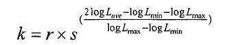
여기서 r 및 s는 상수이고, 여기서 Lmin은 이미지의 최소 휘도이고 Lmax는 최대 휘도이다. Where r and s are constants, where L min is the minimum luminance of the image and L max is the maximum luminance.
식 4는 평균 휘도가 최대 휘도(보다 밝은 이미지)에 보다 가까울 때, 더 우두운 이미지와 더 큰 k 값에 대응하는, 가장 낮은 휘도값에 이미지의 평균 휘도가 더 가까울 때 k의 비교적 낮은 값을 할당하도록 구성된다. 상수들은 예를 들면 상수들 r 및 s의 상이한 값들을 가진 이미지들을 생성하고, 관찰자들의 그룹으로 선호 연구들(preference studies)을 행함으로써 경험적으로 결정될 수 있다. 예를 들면, r이 0.35이고 s가 2인 경우 적절한 값들이 발견되었으면, 식 4는 다음과 같이 된다:Equation 4 gives a relatively low value of k when the average luminance of the image is closer to the lowest luminance value, which corresponds to the darker image and the larger k value, when the average luminance is closer to the maximum luminance (brighter image). Configured to assign. The constants can be determined empirically by, for example, generating images with different values of the constants r and s, and doing preference studies with a group of observers. For example, if r is 0.35 and s is 2, then the appropriate values are found, then Equation 4 becomes:

여기서 k는 0.175 내지 0.70의 범위이다. Where k is in the range of 0.175 to 0.70.
단계(S110)에서, 오프셋은 이미지의 Lave가 0과 1 사이의 비율로 상기와 같이 결정된 키값으로 매핑되도록 결정된다:In step S110, the offset is determined such that L ave of the image is mapped to the key value determined as above at a ratio between 0 and 1.

오프셋은, 미리 선택된 수의 반복들 내에서(예를 들면, 약 20회 반복) 예를 들면 뉴톤 방법과 같은 수치 계산을 사용하여 풀 수 있다. The offset can be solved within a preselected number of iterations (eg about 20 iterations) using, for example, numerical calculations such as the Newton method.
단계(S112)에서, 이미지(200)는 예를 들면 블록들(202)과 같은 영역들로 분할될 수 있다(도 4). 블록들은 동일한 크기 및 형상이 되거나 또는 상이할 수도 있다. 예를 들면, 삼각형들 또는 육각형들과 같은 다른 형상의 블록들도 있지만, 매트릭스로 배열된 직사각형 블록들이 또한 고려된다. 블록들은 같은 크기 및 형상이 될 수 있다. 블록들의 크기는 이미지의 해상에 어느 정도 의존할 수 있다. 예를 들면, 이미지(200)는 약 2 내지 약 1000 블록들(202), 예를 들면 약 64 블록들로 분할될 수 있다. 블록들의 크기는 이미지의 픽셀의 수에 부분적으로 의존할 수 있다. 블록들에 너무 적은 수의 픽셀들이 있다면, 계산이 부정확해질 수 있다. 예를 들면, 각각의 블록(202)은 적어도 약 500 픽셀들을 포함할 수 있고, 일 실시예에서, 적어도 약 1000 픽셀들을 포함할 수 있다. In step S112, the
단계(S114)에서, 블록들 각각에 대해, 톤 재생 곡선(TRC)이 로컬 영역의 히 스토그램 조정에 기초하여 계산된다. 특히, 각각의 영역(202)에서의 픽셀들에 대한 D 값들을 포함하는 로컬 히스토그램이 발생되고, 선택된 더 낮은 동작 범위 내의 출력 휘도값들의 세트에 매핑된다. 도 5에 도시된 바와 같이, 히스토그램 등화 매핑 및 선형 매핑을 포함하는 히스토그램 조정에 대한 다양한 방법들이 존재한다. 선형 매핑 방법에서, 블록의 모든 픽셀들에 대한 D 값들의 입력 히스토그램은 선형 매핑 함수를 사용하여 출력 히스토그램에 매핑된다(출력 D 값은 입력 D 값에 정비례한다). 예를 들면, 히스토그램의 최소 휘도는 더 낮은 동작 범위의 최소 휘도와 같고, 히스토그램의 최대 휘도는 더 낮은 동작 범위의 최대 휘도와 같을 수 있다. 그 다음, 밝기의 나머지 값들은 이들 한도들 사이의 보간에 의해 구성된다. 히스토그램 등화 매핑은 이미지 픽셀들의 밝기 랭킹을 유지하지만, 동일한 수의 픽셀들이 각각의 가능한 밝기값을 갖도록 밝기값들을 재분배한다. 이러한 방법은, 동일하거나 유사한 입력 D값들을 갖는 픽셀들의 큰 집중(concentration)이 있는 범위(더 높은 콘트라스트를 제공함)에 이르고, 보다 적은 픽셀들이 있는 범위를 압축한다. In step S114, for each of the blocks, the tone reproduction curve TRC is calculated based on the histogram adjustment of the local area. In particular, a local histogram is generated that includes the D values for the pixels in each
한 실시예에서, TRC들을 계산하는데 사용된 기술은 2개 이상의 매핑 기술들의 가중된 평균인 매핑 함수에 기초한다. 매핑 함수는 히스토그램 등화 매핑 함수와 선형 매핑 함수의 가중된 평균이 될 수 있다. 상기 방법은 균일성의 임계 레벨을 초과하는 이미지의 임의의 영역들을 검출하고 검출된 영역들의 선형 매핑 함수에 더 큰 가중을 두기 위해 이 매핑 함수를 국부적으로 조정하는 단계를 포함할 수 있다. In one embodiment, the technique used to calculate the TRCs is based on a mapping function that is a weighted average of two or more mapping techniques. The mapping function may be a weighted average of the histogram equalization mapping function and the linear mapping function. The method may include detecting any regions of the image that exceed a threshold level of uniformity and locally adjusting this mapping function to place a greater weight on the linear mapping function of the detected regions.
예를 들면 매핑 함수는, 식 6에 기술된 바와 같이, 적절히 결정된 오프셋으 로 초기의 대수 압축 후에, 히스토그램 등화 매핑 함수와 선형 매핑 함수의 가중된 평균일 수 있다. 이러한 히스토그램 조정 기술은, 2004년 ICPR2004, 17차 패턴 인식에 관한 국제 회의, 2권 847 내지 850면의 J.Duan 및 G. Qiu에 의한 "Fast Tone Mapping for High Dynamic Range Images"에 기술된 방법에 기초한다. 이 기술은 원래 글로벌 톤 매핑을 위해 설계되었다: For example, the mapping function may be the weighted average of the histogram equalization mapping function and the linear mapping function after initial logarithmic compression with an appropriately determined offset, as described in Equation 6. This histogram adjustment technique is described in the method described in 2004 ICPR2004, International Conference on 17th Pattern Recognition, Vol. 2, pp. 847-850, by "Fast Tone Mapping for High Dynamic Range Images" by J. Duan and G. Qiu. Based. This technique was originally designed for global tone mapping:
![]()
![]()
여기서,0 ≤β≤1이다. EC는 초기 대수 압축 후의 히스토그램 등화 매핑이고 LC는 초기 대수 압축 후의 선형 매핑이다. β= 0으로 설정하면, 매핑은 선형이고, β= 1이면, 매핑은 히스토그램 등화된다. 일반적으로 더 큰 값들의 β는 더 많은 콘트라스트를 가진 이미지들을 생성하는데, 그 이유는 이것이 보다 많이 등화 방법을 가중화하기 때문이다. Here, 0 ≦ β ≦ 1. EC is histogram equalization mapping after initial logarithmic compression and LC is linear mapping after initial logarithmic compression. If beta = 0, the mapping is linear; if beta = 1, the mapping is histogram equalized. In general, larger values of β produce images with more contrast because this weights the equalization method more.
예를 들면, Trifonov 등에 의한 미국 특허 제6,826,310호에 기술된 바와 같은 다른 히스토그램 등화 기술들이 TRC를 생성하기 위해 고려된다. For example, other histogram equalization techniques as described in US Pat. No. 6,826,310 to Trifonov et al. Are contemplated for generating TRCs.
상기 약술된 로컬 콘트라스트 향상 방법은 매우 상이한 값들로 매핑되는 유사한 픽셀들의 균일한 영역들(204)을 유발할 수 있다. 이것은 잡음을 유발하는 경향이 있다. 이를 해결하기 위한 한 방법은 균일한 영역들을 검출한 다음 이 영역에서의 콘트라스트 향상을 감소시키는 것이다(단계 S116). 상이한 로컬 영역들에 대한 파라미터 β를 자동으로 결정하기 위해 적응적 방법이 사용될 수 있다. 예를 들면, 히스토그램 값들에 대해 계산된 확산(spread)의 임의의 측정이 계산될 수 있 다. 샘플 측정들은 분산, 표준 편차, 범위(range), 사분위간(inter-quartile) 편차 등이 될 수 있다. 이 측정이 미리 결정된 임계값보다 더 큰 경우(예를 들면, 분산이 확산의 측정으로 사용되는 경우에 약 18.8이 임계값으로 사용될 수 있다), 그것은 균일한 블록으로 간주된다. 그 후, 로컬 히스토그램 조정 기술(식 6)에서 비교적 더 작은 파라미터 β가 사용된다. 이것은 이 영역에 더 작은 콘트라스트 향상을 제공한다. The local contrast enhancement method outlined above may result in
각 블록을 개별적으로 처리하는 콘트라스트 향상의 대표적 방법은 매우 상이한 값들로 매핑되는 유사한 픽셀들의 인접한 영역들을 유발할 수 있다. 한 실시예에서, 한 블록에서 다음 블록으로의 급격한 변화들을 감소시키기 위하여 평탄화 방법(단계 S116)이 사용된다. 평탄화 기술은 픽셀이 존재하는 블록들로부터의 TRC뿐만 아니라 인접한 블록들(최대 8개까지)의 TRC들에 의해 제공된 출력 P 매핑값의 가중된 평균을 생성하는 거리 가중 함수를 포함할 수 있다. 가중은 각각의 블록의 중간으로부터 픽셀의 거리에 반비례할 수 있다. 따라서, 픽셀이 블록들 사이의 에지에 더 가까울 때, 인접한 블록의 TRC에 더 큰 가중을 둔다. 가중 함수는, 각각의 이웃하는 블록에 대한 평균 D값과 픽셀 입력 D 값 사이의 유사성을 고려하는 유사성 함수에 따라 더 수정될 수 있다. A representative method of contrast enhancement of processing each block individually can lead to adjacent areas of similar pixels that map to very different values. In one embodiment, a planarization method (step S116) is used to reduce abrupt changes from one block to the next. The planarization technique may include a distance weighting function that produces a weighted average of the output P mapping values provided by the TRCs of adjacent blocks (up to eight) as well as the TRCs from blocks in which the pixel is present. The weighting may be inversely proportional to the distance of the pixel from the middle of each block. Thus, when the pixel is closer to the edge between blocks, it puts a greater weight on the TRC of the adjacent block. The weighting function can be further modified according to the similarity function taking into account the similarity between the average D value and the pixel input D value for each neighboring block.
예를 들면, 도 6에 도시된 바와 같이, 이미지의 각 픽셀 D(x,y)(식 2로부터 결정됨)에 대해, 이웃하는 블록들에서 전개된 TRC들은 TRC1[D(x,y)], TRC2, [D(x,y)], TRC3[D(x,y)] ... TRC9[D(x,y)]로 이송하기 위해 사용된다. 그 다음, 최 종 매핑된 픽셀값은 다음과 같은 유사성 가중 함수 및 거리 가중 함수에 따라, TRC1[D(x,y)], TRC2, [D(x,y)], TRC3[D(x,y)] 등의 가중된 평균으로 계산될 수 있다:For example, as shown in FIG. 6, for each pixel D (x, y) (determined from equation 2) of the image, the TRCs developed in neighboring blocks are TRC 1 [D (x, y)]. , TRC 2 , [D (x, y)], TRC 3 [D (x, y)] ... used to transfer to TRC 9 [D (x, y)]. The final mapped pixel value is then TRC 1 [D (x, y)], TRC 2 , [D (x, y)], TRC 3 [D according to the similarity weighting function and the distance weighting function (x, y)] can be calculated as a weighted average of:

여기서,here,


여기서, wd(n)은 거리 가중 함수이며, σd는 상수이고(예를 들면 18), dn은 도 6에 도시된 바와 같이 현재 픽셀 위치와 이웃하는 블록들의 중심 사이의 유클리드 거리이며, ws(n)은 유사성 가중 함수이고, σd는 상수이고(예를 들면 0.1), Sn은 현재 픽셀 값과 이웃하는 블록들의 평균 픽셀 값(Dmeann) 사이의 정규화된 차이다.Where w d (n) is the distance weighting function, σ d is a constant (eg 18), d n is the Euclidean distance between the current pixel position and the center of neighboring blocks, as shown in FIG. 6, w s (n) is a similarity weighting function, σ d is a constant (eg 0.1) and S n is a normalized difference between the current pixel value and the average pixel value Dmean n of neighboring blocks.
거리 가중 함수는 픽셀이 위치되는 블록에 대한 TRC에 최대 가중을 항상 할당하기 때문에 로컬 콘트라스트의 보존(preservation)을 선호하는 반면, 유사성 가중 함수는 균일한 영역들에서 유사한 픽셀들이 상이한 블록들로 나누어지는 경우일 지라도 유사한 값들로 매핑되는 기회를 증가시킨다. 네트 효과(net effect)는 매핑된 이미지들이 로컬 콘트라스트를 보전하고 그렇지 않으면 균일한 영역들에 오브젝트들의 윤곽들에 가깝게 발생하려는 경향이 있는 할로 아티팩트들을 제거한다는 것이다. The distance weighting function prefers preservation of local contrast because it always assigns the maximum weight to the TRC for the block in which the pixel is located, while the similarity weighting function divides similar pixels into different blocks in uniform regions. Even in cases it increases the chance of mapping to similar values. The net effect is that the mapped images preserve local contrast and otherwise eliminate halo artifacts that tend to occur close to the contours of the objects in uniform regions.
선택적으로, 하나의 블록의 모든 픽셀들에 대해 거리 가중 함수를 계산함으로써 계산을 감소시킬 수 있다. 그 후 계산된 값들은 픽셀들과 이웃하는 센터들 사이의 상대 거리들이 항상 동일(균일한 크기 및 형상의 블록들로 가정)하기 때문에 다른 블록들 모두에 사용될 수 있다. 부가적으로, 유사성 함수의 계산은 룩업 테이블을 사용하여 근사화될 수 있다. 알고리즘을 가속화하기 위한 대안적 전략은 저해상도 이미지들에 대한 값들을 계산한 다음 보간을 통해 원래 크기로 다시 돌아가는 것이다. Optionally, the calculation can be reduced by calculating the distance weighting function for all pixels of one block. The calculated values can then be used for all other blocks because the relative distances between the pixels and neighboring centers are always the same (assuming blocks of uniform size and shape). Additionally, the calculation of the similarity function can be approximated using a lookup table. An alternative strategy to accelerate the algorithm is to calculate the values for the low resolution images and then revert back to the original size through interpolation.
단계(S 118)에서, RGB 출력은 식 7을 사용하여 결정된 Pmapped 휘도값들 및 오리지널 RGB 값들의 함수로서 재구성된다. 선택적으로 이들은 다음의 식을 사용하여 결정될 수 있다:In
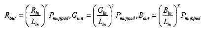
여기서 감마 파라미터 γ는 매핑된 이미지의 컬러를 제어하는 상수이다. 예를 들면, γ는 0.5로 설정된다. The gamma parameter γ is a constant that controls the color of the mapped image. For example, γ is set to 0.5.
상술한 방법은 여러 이점들을 가진다. 첫째, 로컬 히스토그램 조정은 글로벌 매핑에 의존하는 히스토그램 조정 방법들로 달성될 수 있는 것보다 더 큰 콘트라스트를 달성하도록 허용한다. 둘째, 초기의 동작 범위의 감소는 대수 압축이며, 여기서 전체 밝기는 뉴톤 방법을 사용하여 자동으로 설정될 수 있다. 이것은 인간의 상호 작용에 대한 요구를 감소시키며, 예를 들면 사진관 환경에서 이미지들의 자동화된 대량 프린트에 적절한 기술을 렌더링한다. 넷째, 이 방법은 할로 효과들을 최소화하고 균일한 영역들이 유사한 방식들로 처리되도록 허용한다. 이미지의 상이한 영역들에서의 β의 상이한 값들을 사용함으로써, 콘트라스트가 그렇게 하기에 적합한 곳에 제공되도록 허용한다. 확산의 히스토그램 측정들에 기초하여, β를 자동으로 결정하는 방법이 또한 제공된다. The method described above has several advantages. First, local histogram adjustment allows to achieve greater contrast than can be achieved with histogram adjustment methods that rely on global mapping. Second, the reduction in the initial operating range is logarithmic compression, where the overall brightness can be automatically set using the Newton method. This reduces the need for human interaction and renders a technique suitable for automated mass printing of images, for example in a photo studio environment. Fourth, this method minimizes halo effects and allows uniform regions to be processed in similar ways. By using different values of β in different regions of the image, the contrast is allowed to be provided where appropriate. Based on histogram measurements of diffusion, a method is also provided for automatically determining β.
상기 방법은 대표적인 디폴트 파라미터들을 가진 광범위한 높은 동작 범위 이미지들에 대해 테스트되었고, 매우 긍정적인 결과들을 보여준다. 기존의 톤 재생 방법들에 비해, 일관성 있게 양호한 재생은 본 방법을 사용하여 인간 입력에 대한 요구 없이 달성된다. The method has been tested on a wide range of high range images with representative default parameters and shows very positive results. Compared with existing tone reproduction methods, consistently good reproduction is achieved using this method without the need for human input.
상기 방법은, 프린터들 및 CRT 모니터들과 같은 종래의 8-비트의 낮은 동작 범위 재생 디바이스들에 대한 시각화(visualization)에 적합한 형태로 높은 동작 범위 이미지 데이터(일반적으로 채널당 12 또는 16, 또는 심지어 32비트들)의 변환에서 응용을 발견한다. 재생된 이미지들을 보기 좋게 하고 시각 경험을 유발하게 함으로써, 프린트 산업, 사진 산업 및 컴퓨터 그래픽스에 초점을 맞춘다. 본 기술은 그 목적을 달성할 수 있고, 사용자 평가들에서 최상의 기존 기술들과의 매우 비교 가능한 성능을 보여준다. 그 외에도, 이 기술이 고속이고 완전히 자동적이기 때 문에, 자동 프린팅 파이프라인에 포함될 수 있다. The method is characterized by high operating range image data (generally 12 or 16, or even 32 per channel) in a form suitable for visualization for conventional 8-bit low operating range playback devices such as printers and CRT monitors. Finds application in the conversion of bits). It focuses on the print industry, photography industry and computer graphics by making the reproduced images look good and induce visual experience. The technique can achieve its purpose and show very comparable performance with the best existing techniques in user ratings. In addition, because the technology is fast and fully automatic, it can be included in the automatic printing pipeline.
본 발명에 의한 톤 재생 방법은, 아티팩트들을 도입하지 않고, 배경들의 로컬 콘트라스트 및 미세한 세부들을 완전 자동 및 고속으로 재생할 수 있다. The tone reproduction method according to the present invention can reproduce local contrast and fine details of backgrounds at full automatic and high speed without introducing artifacts.
Claims (10)


Applications Claiming Priority (2)
| Application Number | Priority Date | Filing Date | Title |
|---|---|---|---|
| US11/435,588 US7636496B2 (en) | 2006-05-17 | 2006-05-17 | Histogram adjustment for high dynamic range image mapping |
| US11/435,588 | 2006-05-17 |
Publications (2)
| Publication Number | Publication Date |
|---|---|
| KR20070111391A KR20070111391A (en) | 2007-11-21 |
| KR101309497B1 true KR101309497B1 (en) | 2013-09-24 |
Family
ID=38461047
Family Applications (1)
| Application Number | Title | Priority Date | Filing Date |
|---|---|---|---|
| KR1020070048029A KR101309497B1 (en) | 2006-05-17 | 2007-05-17 | Histogram adjustment for high dynamic range image mapping |
Country Status (5)
| Country | Link |
|---|---|
| US (1) | US7636496B2 (en) |
| EP (1) | EP1857975B1 (en) |
| JP (1) | JP4870617B2 (en) |
| KR (1) | KR101309497B1 (en) |
| DE (1) | DE602007005863D1 (en) |
Families Citing this family (57)
| Publication number | Priority date | Publication date | Assignee | Title |
|---|---|---|---|---|
| US7684640B2 (en) * | 2005-10-20 | 2010-03-23 | Sharp Laboratories Of America, Inc. | Methods and systems for automatic digital image enhancement with local adjustment |
| EP1840831A1 (en) * | 2006-03-31 | 2007-10-03 | Sony Deutschland Gmbh | Adaptive histogram equalization for images with strong local contrast |
| JP4406443B2 (en) * | 2007-05-09 | 2010-01-27 | 株式会社東芝 | Image correction device |
| US7706034B2 (en) * | 2007-09-11 | 2010-04-27 | Xerox Corporation | Multi-Dimensional look-up table generation via adaptive node selection based upon color characteristics of an input image |
| US8107756B2 (en) * | 2007-10-11 | 2012-01-31 | Himax Technologies Limited | Digital image tone remapping method and apparatus |
| WO2009086083A2 (en) * | 2007-12-21 | 2009-07-09 | Mks Instruments, Inc. | Hierarchically organizing data using a partial least squares analysis (pls-trees) |
| WO2012118961A1 (en) | 2011-03-02 | 2012-09-07 | Dolby Laboratories Licensing Corporation | Local multiscale tone-mapping operator |
| US8126858B1 (en) | 2008-01-23 | 2012-02-28 | A9.Com, Inc. | System and method for delivering content to a communication device in a content delivery system |
| US8165393B2 (en) * | 2008-06-05 | 2012-04-24 | Microsoft Corp. | High dynamic range texture compression |
| US20090322777A1 (en) * | 2008-06-26 | 2009-12-31 | Microsoft Corporation | Unified texture compression framework |
| US8194992B2 (en) * | 2008-07-18 | 2012-06-05 | Xerox Corporation | System and method for automatic enhancement of seascape images |
| JP5271631B2 (en) * | 2008-08-07 | 2013-08-21 | Hoya株式会社 | Image processing unit, imaging device, composite image creation program |
| US8339475B2 (en) * | 2008-12-19 | 2012-12-25 | Qualcomm Incorporated | High dynamic range image combining |
| US20100157079A1 (en) | 2008-12-19 | 2010-06-24 | Qualcomm Incorporated | System and method to selectively combine images |
| US9025898B2 (en) * | 2009-04-06 | 2015-05-05 | Red Hat Israel, Ltd. | Dynamically selecting compression method for graphics remoting |
| JP4795473B2 (en) * | 2009-06-29 | 2011-10-19 | キヤノン株式会社 | Image processing apparatus and control method thereof |
| CN102473295B (en) | 2009-06-29 | 2016-05-04 | 汤姆森特许公司 | Based on the tone mapping in district |
| US8346009B2 (en) | 2009-06-29 | 2013-01-01 | Thomson Licensing | Automatic exposure estimation for HDR images based on image statistics |
| JP5628306B2 (en) * | 2009-06-29 | 2014-11-19 | トムソン ライセンシングThomson Licensing | Contrast improvement |
| US8345975B2 (en) * | 2009-06-29 | 2013-01-01 | Thomson Licensing | Automatic exposure estimation for HDR images based on image statistics |
| US8457398B2 (en) * | 2009-10-27 | 2013-06-04 | Himax Media Solutions, Inc. | Image enhancement method and apparatuses utilizing the same |
| KR101648762B1 (en) * | 2009-11-03 | 2016-08-18 | 한양대학교 산학협력단 | Method and Apparatus for converting dynamic ranges of input images |
| JP5397190B2 (en) * | 2009-11-27 | 2014-01-22 | ソニー株式会社 | Image processing apparatus, image processing method, and program |
| US8606009B2 (en) * | 2010-02-04 | 2013-12-10 | Microsoft Corporation | High dynamic range image generation and rendering |
| US8314847B2 (en) | 2010-05-25 | 2012-11-20 | Apple Inc. | Automatic tone mapping curve generation based on dynamically stretched image histogram distribution |
| WO2012017946A1 (en) * | 2010-08-04 | 2012-02-09 | 日本電気株式会社 | Image processing method, image processing device and image processing program |
| US8990199B1 (en) | 2010-09-30 | 2015-03-24 | Amazon Technologies, Inc. | Content search with category-aware visual similarity |
| US8463036B1 (en) | 2010-09-30 | 2013-06-11 | A9.Com, Inc. | Shape-based search of a collection of content |
| US8422782B1 (en) | 2010-09-30 | 2013-04-16 | A9.Com, Inc. | Contour detection and image classification |
| US8374428B2 (en) | 2010-12-05 | 2013-02-12 | Microsoft Corporation | Color balancing for partially overlapping images |
| JP5828649B2 (en) * | 2011-03-09 | 2015-12-09 | キヤノン株式会社 | Image processing apparatus, image processing method, and computer program |
| US8947555B2 (en) * | 2011-04-18 | 2015-02-03 | Qualcomm Incorporated | White balance optimization with high dynamic range images |
| KR20200074229A (en) * | 2011-05-27 | 2020-06-24 | 돌비 레버러토리즈 라이쎈싱 코오포레이션 | Scalable systems for controlling color management comprising varying levels of metadata |
| EP2769540B1 (en) * | 2011-10-20 | 2018-11-28 | Dolby Laboratories Licensing Corporation | Method and system for video equalization |
| KR101349968B1 (en) * | 2011-11-28 | 2014-01-14 | 네이버 주식회사 | Image processing apparatus and method for automatically adjustment of image |
| TWI463879B (en) * | 2011-12-26 | 2014-12-01 | Univ Nat Chunghsing | Modulated image processing method and system thereof |
| US8970739B2 (en) * | 2012-03-05 | 2015-03-03 | Apple Inc. | Devices and methods for creating structure histograms for use in image enhancement |
| CN102819852B (en) * | 2012-05-31 | 2017-12-29 | 新奥特(北京)视频技术有限公司 | A kind of method for generating halation in the picture |
| WO2014012680A1 (en) | 2012-07-18 | 2014-01-23 | Thomson Licensing | Method and device for converting an image sequence whose luminance values belong to a span of values with large dynamic range |
| KR101389930B1 (en) * | 2012-08-17 | 2014-04-29 | 연세대학교 산학협력단 | Apparatus and method for performing tone mapping for image |
| WO2014118032A1 (en) * | 2013-01-29 | 2014-08-07 | Thomson Licensing | Method and device for modifying the dynamic range of an image |
| CN104715445B (en) * | 2013-12-13 | 2018-04-06 | 腾讯科技(深圳)有限公司 | Image processing method and system |
| US9420145B2 (en) * | 2014-01-13 | 2016-08-16 | Marvell World Trade Ltd. | System and method for tone mapping of images |
| CN104463820A (en) * | 2014-10-29 | 2015-03-25 | 广东工业大学 | Reverse tone mapping algorithm based on frequency domain |
| US9860504B2 (en) | 2015-01-09 | 2018-01-02 | Vixs Systems, Inc. | Color gamut mapper for dynamic range conversion and methods for use therewith |
| US9652870B2 (en) * | 2015-01-09 | 2017-05-16 | Vixs Systems, Inc. | Tone mapper with filtering for dynamic range conversion and methods for use therewith |
| EP3054418A1 (en) * | 2015-02-06 | 2016-08-10 | Thomson Licensing | Method and apparatus for processing high dynamic range images |
| JP6613697B2 (en) * | 2015-08-06 | 2019-12-04 | 株式会社リコー | Image processing apparatus, program, and recording medium |
| CN105608685B (en) * | 2015-11-17 | 2018-09-28 | 江苏理工学院 | A kind of secondary histogram equalization image enchancing method and system of histogram modification |
| CN107292829B (en) * | 2016-03-31 | 2020-12-15 | 阿里巴巴集团控股有限公司 | Image processing method and device |
| CN108460730B (en) * | 2017-02-17 | 2020-06-26 | 京东方科技集团股份有限公司 | Image processing method and device |
| DE102017218072A1 (en) | 2017-10-11 | 2019-04-11 | Robert Bosch Gmbh | Method for taking a picture |
| US10504452B2 (en) * | 2018-03-12 | 2019-12-10 | Apple Inc. | Pixel contrast control systems and methods |
| TWI681675B (en) * | 2018-07-04 | 2020-01-01 | 瑞昱半導體股份有限公司 | Contrast enhancement method based on dynamic range compression and electronic apparatus thereof |
| JP7212466B2 (en) * | 2018-07-06 | 2023-01-25 | キヤノン株式会社 | Image processing device, image processing method, program, storage medium |
| US11049224B2 (en) | 2018-12-05 | 2021-06-29 | Microsoft Technology Licensing, Llc | Automated real-time high dynamic range content review system |
| CN112351195B (en) * | 2020-09-22 | 2022-09-30 | 北京迈格威科技有限公司 | Image processing method, device and electronic system |
Family Cites Families (12)
| Publication number | Priority date | Publication date | Assignee | Title |
|---|---|---|---|---|
| US4654722A (en) * | 1985-05-06 | 1987-03-31 | Eastman Kodak Company | Tone value sample selection in digital image processing method employing histogram normalization |
| US5450502A (en) * | 1993-10-07 | 1995-09-12 | Xerox Corporation | Image-dependent luminance enhancement |
| US5724456A (en) * | 1995-03-31 | 1998-03-03 | Polaroid Corporation | Brightness adjustment of images using digital scene analysis |
| US5581370A (en) * | 1995-06-05 | 1996-12-03 | Xerox Corporation | Image-dependent automatic area of interest enhancement |
| US5822453A (en) | 1996-12-10 | 1998-10-13 | Eastman Kodak Company | Method for estimating and adjusting digital image contrast |
| US6175427B1 (en) * | 1998-04-20 | 2001-01-16 | Xerox Corporation | System and method of tonal correction of independent regions on a compound document |
| US6850642B1 (en) * | 2000-01-31 | 2005-02-01 | Micron Technology, Inc. | Dynamic histogram equalization for high dynamic range images |
| US6826310B2 (en) * | 2001-07-06 | 2004-11-30 | Jasc Software, Inc. | Automatic contrast enhancement |
| US7136073B2 (en) * | 2002-10-17 | 2006-11-14 | Canon Kabushiki Kaisha | Automatic tone mapping for images |
| JP4303061B2 (en) * | 2003-08-28 | 2009-07-29 | 富士フイルム株式会社 | Image processing apparatus and method, and program |
| US7492375B2 (en) * | 2003-11-14 | 2009-02-17 | Microsoft Corporation | High dynamic range image viewing on low dynamic range displays |
| JP3956311B2 (en) * | 2004-02-19 | 2007-08-08 | オムロン株式会社 | Image data conversion device and camera device |
-
2006
- 2006-05-17 US US11/435,588 patent/US7636496B2/en not_active Expired - Fee Related
-
2007
- 2007-05-14 EP EP07108101A patent/EP1857975B1/en not_active Expired - Fee Related
- 2007-05-14 DE DE602007005863T patent/DE602007005863D1/en active Active
- 2007-05-17 KR KR1020070048029A patent/KR101309497B1/en not_active IP Right Cessation
- 2007-05-17 JP JP2007131454A patent/JP4870617B2/en not_active Expired - Fee Related
Non-Patent Citations (2)
| Title |
|---|
| Erik Reinhard., ‘Parameter Estimation for Photographic Tone Reproduction’, journal of graphics tools, 2002. |
| Erik Reinhard., 'Parameter Estimation for Photographic Tone Reproduction', journal of graphics tools, 2002. * |
Also Published As
| Publication number | Publication date |
|---|---|
| EP1857975A3 (en) | 2008-04-02 |
| KR20070111391A (en) | 2007-11-21 |
| EP1857975A2 (en) | 2007-11-21 |
| EP1857975B1 (en) | 2010-04-14 |
| JP2007310886A (en) | 2007-11-29 |
| DE602007005863D1 (en) | 2010-05-27 |
| JP4870617B2 (en) | 2012-02-08 |
| US20070268534A1 (en) | 2007-11-22 |
| US7636496B2 (en) | 2009-12-22 |
Similar Documents
| Publication | Publication Date | Title |
|---|---|---|
| KR101309497B1 (en) | Histogram adjustment for high dynamic range image mapping | |
| KR101309498B1 (en) | Histogram adjustment for high dynamic range image mapping | |
| US7158686B2 (en) | Enhancing the tonal characteristics of digital images using inflection points in a tone scale function | |
| US7116838B2 (en) | Enhancing the tonal and spatial characteristics of digital images using selective spatial filters | |
| EP2076013B1 (en) | Method of high dynamic range compression | |
| US7043090B2 (en) | Enhancing the tonal characteristics of digital images using expansive and compressive tone scale functions | |
| KR101012270B1 (en) | Methods and systems for converting images from low dynamic range to high dynamic range | |
| JP5105209B2 (en) | Image processing apparatus and method, program, and recording medium | |
| US7058234B2 (en) | Enhancing the tonal, spatial, and color characteristics of digital images using expansive and compressive tone scale functions | |
| EP1377029A2 (en) | Enhancing the tonal characteristics of digital images | |
| US7130485B2 (en) | Enhancing the tonal and color characteristics of digital images using expansive and compressive tone scale functions | |
| JP4639037B2 (en) | Image processing method and apparatus | |
| Fairchild et al. | Image appearance modeling | |
| JP4324044B2 (en) | Image processing apparatus and method | |
| JP4219577B2 (en) | Image processing apparatus, image output apparatus, image processing method, and storage medium | |
| JP3817371B2 (en) | Image processing method, apparatus, and recording medium | |
| Lee et al. | Complex adaptation-based LDR image rendering for 3D image reconstruction | |
| JP2003125213A5 (en) | ||
| Kotera | Overview Paper: Intelligent color imaging |
Legal Events
| Date | Code | Title | Description |
|---|---|---|---|
| A201 | Request for examination | ||
| E902 | Notification of reason for refusal | ||
| E701 | Decision to grant or registration of patent right | ||
| GRNT | Written decision to grant | ||
| LAPS | Lapse due to unpaid annual fee |