JP4310918B2 - Information recording apparatus, information recording method, and recording medium - Google Patents
Information recording apparatus, information recording method, and recording medium Download PDFInfo
- Publication number
- JP4310918B2 JP4310918B2 JP2000384733A JP2000384733A JP4310918B2 JP 4310918 B2 JP4310918 B2 JP 4310918B2 JP 2000384733 A JP2000384733 A JP 2000384733A JP 2000384733 A JP2000384733 A JP 2000384733A JP 4310918 B2 JP4310918 B2 JP 4310918B2
- Authority
- JP
- Japan
- Prior art keywords
- data
- discrete cosine
- cosine transform
- special reproduction
- field
- Prior art date
- Legal status (The legal status is an assumption and is not a legal conclusion. Google has not performed a legal analysis and makes no representation as to the accuracy of the status listed.)
- Expired - Fee Related
Links
Images


Landscapes
- Television Signal Processing For Recording (AREA)
- Compression Or Coding Systems Of Tv Signals (AREA)
Description
【0001】
【発明の属する技術分野】
本発明は、情報記録装置および情報記録方法、並びに記録媒体に関し、特に、各マクロブロックのDCT種別を判定し、DCT種別に対応した処理を実行することにより、高画質の特殊再生用データを生成することができる、情報記録装置および情報記録方法、並びに記録媒体に関する。
【0002】
【従来の技術】
近年、高能率符号化により圧縮されたデータを記録する技術が一般に普及している。代表的な高能率圧縮符号化方式には、例えば、MPEG(Moving Picture Coding Experts Group/Moving Picture Experts Group)2などがある。MPEG2は、ISO(International Organization For Standardization:国際標準化機構)で制定された、デジタル動画と音声の圧縮および伸長に関する規格であり、動き保証予測符号化と、離散コサイン変換(DCT:Discrete Cosine Transform)符号化を組み合わせたハイブリッド符号化方式である。すなわち、MPEG2とは、ビデオ信号のフレーム間の差分を取ることにより、時間軸方向の冗長度を落とし、DCTを用いて、空間軸方向の冗長度を落とすことにより、ビデオ信号を効率よく符号化することができる圧縮符号化方式である。
【0003】
MPEG2においては、まず、16画素×16ラインのマクロブロック単位で動き補償が行われ、次に、8画素×8ラインのサブブロックで、DCTにより、DCT係数が生成される。MPEG2においては、図1に示されるように、フレームDCTと、フィールドDCTの2種類のDCTが存在し、ピクチャがフレーム構造の場合、マクロブロック単位でフレームDCTとフィールドDCTを切り替えることができる。
【0004】
フレームDCTにおいては、図1(A)に示されるように、16画素×16ラインのマクロブロックから、フィールド毎に分割されることなく、そのまま、8画素×8ラインで構成される4つのサブブロックに分解される。一方、フィールドDCTにおいては、図1(B)に示されるように、16画素×16ラインのマクロブロックから、奇数ラインと偶数ラインに分割されることにより、それぞれ、トップフィールド、もしくはボトムフィールドのいずれかのフィールドで形成される8画素×8ラインの4つのサブブロックに分解される。
【0005】
DCT係数が生成された後、量子化ステップ制御、およびハフマン符号化を経て、符号化が終了し、例えば、磁気テープなどの所定の記録媒体に、符号化されたデータが記録される。MPEG2で圧縮符号化されたデータを復号する場合には、この逆の手順を行えばよい。
【0006】
このような、高能率符号化を施された画像データを、圧縮し、磁気テープなどの記録媒体に記録、または再生する、例えば、デジタルVTRなどの記録再生装置においては、例えば、サーチ再生など、通常の再生と異なる再生(以下、特殊再生と称する)に必要なデータ(以下、特殊再生用データと称する)が、画像データとともに記録されるようになされている。
【0007】
磁気テープなどの記録媒体の記憶容量を有効に利用するために、特殊再生用データのデータ量は、少ないことが望ましい。図2は、データ量の少ない特殊再生用データを生成するための、従来の磁気テープ記録装置1の構成(もしくは、デジタルVTRなどの磁気テープ記録再生装置のうち、記録系の部分の構成)を示すブロック図である。
【0008】
画像データ符号化部11は、入力されたベースバンドのビデオ信号を、例えば、MP@HLあるいはMP@H-14などのMPEG2方式で圧縮する。圧縮された信号は、再生用の主画像データとして、多重化部17に供給されるとともに、特殊再生用データを生成するために、イントラフレーム分離部12に供給される。
【0009】
イントラフレーム分離部12は、画像データ符号化部11より入力されたビデオデータから、イントラフレームのみで構成されたIピクチャを分離し、DC成分抽出部13および逆DCT処理部14に供給する。
【0010】
DC成分抽出部13は、イントラフレーム分離部12から供給されたIピクチャのDCT係数から、DC成分を抽出し、それを特殊再生用データとして、スイッチ15に出力する。
【0011】
逆DCT処理部14は、イントラフレーム分離部12から供給されたIピクチャのDCT係数から、DC成分に加えて、DCT係数の低域成分、すなわち、低次のAC成分を抽出するとともに、逆DCT変換を施す。その結果算出された画素値(輝度値および色差)が、特殊再生用データとなり、スイッチ15に出力される。
【0012】
スイッチ15は、図示せぬ制御部により切り替えられ、DC成分抽出部13または逆DCT処理部14で生成された特殊再生用データを、データ長調整部16に供給する。
【0013】
データ長調整部16は、DC成分抽出部13、もしくは、逆DCT処理部14から入力されたデータの長さを調整(制限)し、多重化部17に供給する。
【0014】
多重化部17には、画像データ符号化部11から入力される主画像データおよびデータ長調整部16から入力される特殊再生用データの他、別途供給される圧縮されたオーディオデータおよび所定のシステムデータ(例えば、AUXデータなど)が供給される。多重化部17は、供給されるこれらのデータを多重化し、記録フォーマット部18に供給する。
【0015】
記録フォーマット部18は、多重化部17からの多重化データに対して、誤り訂正符号の付加や、変調処理を施し、図示せぬ回転ヘッドに供給し、磁気テープ19に記録させる。
【0016】
次に、図2の磁気テープ記録装置1の動作について説明する。ビデオ信号は、画像データ符号化部11に入力され、例えば、MP@HLまたはMP@H-14方式で圧縮され、イントラフレーム分離部12および多重化部17に供給される。
【0017】
イントラフレーム分離部12は、入力された主画像データ(Iピクチャ、Pピクチャ、およびBピクチャから構成されているデータ)から、Iピクチャを分離し、DC成分抽出部13および逆DCT処理部14に供給する。特殊再生用データを、DC成分のみから生成する場合、DC成分抽出部13は、供給されたIピクチャのDCT係数から、DC成分を抽出する。具体的には、1つのマクロブロックを構成する、4つのDCTブロック(8画素×8ライン)に分割された輝度信号YのDCT係数のそれぞれから、DC成分が抽出される。また、1つのマクロブロックを構成する1つのDCTブロックに分割された色差信号Crおよび色差信号Cbから、それぞれDC成分が抽出される。
【0018】
例えば、画像フォーマットが、4:2:0である場合、1つのマクロブロックからは、4つの輝度信号と、2つの色差信号を得ることができる。図3(A)は、この例の場合の特殊再生用データであるDC成分が逆変換されて生成された輝度信号Y1乃至Y4、図3(B)は、色差信号Cr1、そして、図3(C)は、色差信号Cb1を表している。すなわち、これらの輝度値および色差により構成される画像が、特殊再生時に表示される。抽出されたこれらのDC成分が、特殊再生用データとして、スイッチ15を介して、データ長調整部16に供給される。
【0019】
特殊再生用データを、DC成分および低次AC成分から生成して、より高画質の特殊再生用データを記録させたい場合、逆DCT処理部14は、イントラフレーム分離部12から供給されたIピクチャのDCT係数から、DC成分に加えて、DCT係数の低域成分、すなわち、低次のAC成分を抽出するとともに、逆DCT変換を施す。その結果算出された画素値(輝度値および色差)が、特殊再生用データとなり、スイッチ15を介して、データ長調整部16に供給される。
【0020】
データ長調整部16は、DC成分抽出部13から供給された、特殊再生用データとしてのDC成分のデータ長を調整する。例えば、輝度信号YのDCT係数から抽出されたDC成分のデータ長は、6ビットに調整(制限)され、また色差信号Cr,CbのDCT係数から抽出されたDC成分は、5ビットに調整(制限)される。データ長調整部16の処理により、特殊再生用データのデータ量の削減と、データ量の固定化を実現することができる。データ長を調整された特殊再生用データは、多重化部17に供給される。
【0021】
多重化部17は、データ長調整部16から供給された特殊再生用データを、画像データ符号化部11から供給される主画像データ、並びに別途供給されるオーディオデータおよびシステムデータとともに多重化し、記録フォーマット部18に供給する。
【0022】
記録フォーマット部18に供給された多重化データは、誤り符号が付加され、変調処理等が施された後、図示せぬ回転ヘッドを介して、磁気テープ19に記録される。
【0023】
【発明が解決しようとする課題】
しかしながら、図2を用いて説明した磁気テープ記録装置1においては、フレームDCTにより符号化されたマクロブロックを考慮して、特殊再生用データが生成されており、フィールドDCTにより符号化されたマクロブロックについては考慮されていなかった。フィールドDCTにより符号化されたマクロブロックに対して、図2を用いて説明した従来の磁気テープ記録装置1を用いて、特殊再生用データを生成すると、ブロックノイズが目立つ、画質の悪い特殊再生用データが生成されてしまう。更に、従来の磁気テープ記録装置1では、DCTサイズを変化させて符号化するといった、DCTレベルにおける解像度の変換による復号化についても考慮されていなかった。
【0024】
本発明はこのような状況に鑑みてなされたものであり、各マクロブロックのDCT種別を判定し、DCT種別に対応した処理を実行することにより、高画質の特殊再生用データを生成することができるようにするものである。
【0025】
【課題を解決するための手段】
本発明の情報記録装置は、主画像データからIピクチャを抽出する抽出手段と、Iピクチャの各マクロブロックが、フレーム離散コサイン変換を施されているか、または、フィールド離散コサイン変換を施されているかを判定する判定手段と、Iピクチャの各マクロブロックのうち、前記フィールド離散コサイン変換を施されたマクロブロックに対して、逆離散コサイン変換を施すことにより、特殊再生用のデータを生成する生成手段と、生成手段により生成された特殊再生用のデータに対して、フィールド入れ替えおよび平均化処理を施す平均化処理手段と、平均化処理手段によりフィールド入れ替えおよび平均化処理が施された特殊再生用のデータと、主画像データとを記録する記録手段とを備えることを特徴とする。
【0028】
生成手段には、フィールド離散コサイン変換が施されたマクロブロックに対して、DC成分および低次のAC成分のデータ以外に全て0を代入し、その結果得られるデータに対して逆離散コサイン変換を施すことにより、特殊再生用のデータを生成させるようにすることができる。
【0030】
生成手段には、フィールド離散コサイン変換が施されたマクロブロックから、DC成分および低次のAC成分のデータのみを抽出し、抽出したDC成分および低次のAC成分のデータに対して、逆離散コサイン変換を施すことにより、特殊再生用のデータを生成させるようにすることができる。
【0034】
本発明の情報記録方法は、主画像データからIピクチャを抽出する抽出ステップと、Iピクチャの各マクロブロックが、フレーム離散コサイン変換を施されているか、または、フィールド離散コサイン変換を施されているかを判定する判定ステップと、Iピクチャの各マクロブロックのうち、フィールド離散コサイン変換を施されたマクロブロックに対して、逆離散コサイン変換を施すことにより、特殊再生用のデータを生成する生成ステップと、生成ステップの処理により生成された特殊再生用のデータに対して、フィールド入れ替えおよび平均化処理を施す平均化処理ステップと、平均化処理ステップの処理によりフィールド入れ替えおよび平均化処理が施された特殊再生用のデータと、前記主画像データとを記録する記録ステップとを含むことを特徴とする。
【0035】
本発明の記録媒体に記録されているプログラムは、主画像データからIピクチャを抽出する抽出ステップと、Iピクチャの各マクロブロックが、フレーム離散コサイン変換を施されているか、または、フィールド離散コサイン変換を施されているかを判定する判定ステップと、Iピクチャの各マクロブロックのうち、フィールド離散コサイン変換を施されたマクロブロックに対して、逆離散コサイン変換を施すことにより、特殊再生用のデータを生成する生成ステップと、生成ステップの処理により生成された特殊再生用のデータに対して、フィールド入れ替えおよび平均化処理を施す平均化処理ステップと、平均化処理ステップの処理によりフィールド入れ替えおよび平均化処理が施された特殊再生用のデータと、前記主画像データとを記録する記録ステップとを含むことを特徴とする。
【0036】
本発明の情報記録装置、情報記録方法、および記録媒体に記録されているプログラムにおいては、主画像データからIピクチャが抽出され、Iピクチャの各マクロブロックが、フレーム離散コサイン変換を施されているか、または、フィールド離散コサイン変換を施されているかが判定され、Iピクチャの各マクロブロックのうち、フィールド離散コサイン変換を施されたマクロブロックに対して、逆離散コサイン変換を施すことにより、特殊再生用のデータが生成され、生成された特殊再生用のデータに対して、フィールド入れ替えおよび平均化処理が施され、フィールド入れ替えおよび平均化処理が施された特殊再生用のデータと、主画像データとが記録される。
【0037】
【発明の実施の形態】
以下、図を参照して、本発明の実施の形態について説明する。
【0038】
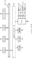
まず、本発明の第1の実施の形態について説明する。図4は、本発明を適用した、磁気テープ記録装置21の構成(もしくは、本発明を適用した、デジタルVTRなどの磁気テープ記録再生装置のうち、記録系の部分の構成)を示すブロック図である。なお、従来の場合と対応する部分には同一の符号を付してあり、その説明は適宜省略する(以下、同様)。
【0039】
すなわち、図4の磁気テープ記録装置21は、新たに、DCT種別判定部31、DC成分抽出部32、DC成分抽出部33、逆DCT処理部34、スイッチ35、およびフィールド平均化処理部36が新たに設けられている以外は、基本的に、図2の磁気テープ記憶装置1と同様の構成を有している。
【0040】
イントラフレーム分離部12において分離されたIピクチャは、DCT種別判定部31に入力される。DCT種別判定部31は、各マクロブロックに対し、そのDCTタイプが、フレームDCTであるか、フィールドDCTであるかを判定し、フレームDCTであった場合は、入力されたデータを、DC成分抽出部32に出力し、フィールドDCTであった場合は、入力されたデータを、DC成分抽出部33および逆DCT処理部34に出力する。
【0041】
DCTタイプがフレームDCTであった場合、DC成分抽出部32は、図2のDC成分抽出部13と同様の処理により、供給されたIピクチャのDCT係数から、DC成分を抽出する。抽出されたDC成分が、特殊再生用データとして、スイッチ15を介して、データ長調整部16に供給される。
【0042】
DCTタイプがフィールドDCTであった場合、DC成分抽出部33に入力されたデータは、図2を用いて説明した場合と同様の処理が施されて、生成された特殊再生用データが、スイッチ35を介して、フィールド平均化処理部36に供給される。
【0043】
そして、逆DCT処理部34に入力されたデータは、そのDC成分および低次AC成分を基に、解像度を変更されることなく、逆DCT処理が施される。図5を用いて、逆DCT処理部34の具体的な処理について説明する。
【0044】
逆DCT処理部34に入力されるデータは、図5(A)に示されるような、8画素×8ラインのサブブロックである。そのうち、所望するDCT係数のみが逆DCTに用いられる。ここでは、DC成分と、1次のAC成分を、逆DCTに用いる場合について説明する。
【0045】
図5(B)に示されるように、逆DCT処理部34において、所定のDCT係数(DC成分および1次のAC成分)以外のDCT係数に0が代入された、新たなサブブロックが作成される。そして、図5(B)に示される新たなサブブロックに対して、8画素×8ラインの逆DCT処理が施され、図5(C)に示されるように、a0乃至a7の8つの値からなる8画素×8ラインのサブブロックが生成される。
【0046】
そして、図5(C)のサブブロックを基に、(a0+a1+a2+a3)/4および(a4+a5+a6+a7)/4が算出されて、図5(D)に示されるように、算出された2つの値からなる8画素×8ラインのサブブロックが生成され、特殊再生用データとして、スイッチ35を介して、フィールド平均化処理部36に供給される。
【0047】
このように、フィールドDCTにより符号化されたマクロブロックに対して、所望するDCT係数(この場合は、DC成分および低次AC成分)のみを抽出して、その他のDCT係数を0にしたサブブロックに対して逆DCT変換を施すことにより、逆DCT変換の計算量を少なくすることができる。
【0048】
スイッチ35は、図示せぬ制御部により切り替えられ、DC成分抽出部33または逆DCT処理部34で生成された特殊再生用データを、フィールド平均化処理部36に供給する。
【0049】
フィールド平均化処理部36は、入力された4つのサブブロックに対して、フィールド入れ替えおよび平均化処理を施して、16画素×16ラインのマクロブロックを、スイッチ15を介して、データ長調整部16に出力する。フィールド入れ替えおよび平均化処理の詳細について、図6乃至図8を用いて説明する。
【0050】
図6(A)に示されるように、フィールド平均化処理部36に入力された4つのサブブロックは、それぞれ、左半分の奇数ラインに相当するサブブロック、右半分の奇数ラインに相当するサブブロック、左半分の偶数ラインに相当するサブブロック、右半分の偶数ラインに相当するサブブロックに割り当てられる。そして、それら4つのサブブロックの割り当てに従って各成分が再配列され、図6(B)に示されるような、16画素×16ラインのマクロブロックが生成される。
【0051】
そして、図6(B)に示される16画素×16ラインのマクロブロックが、8画素×8ラインの4つのエリアに分割されて、それぞれのエリアにおいて、平均化処理が行われるので、その結果、図6(C)に示される、16画素×16ラインのマクロブロックが得られる。
【0052】
DC成分抽出部33から出力されるサブブロックは、それぞれのラインが同じ値を有している。従って、図7(A)に示されるように、それぞれのラインの値がAであるサブブロック、それぞれのラインの値がBであるサブブロック、それぞれのラインの値がCであるサブブロック、および、それぞれのラインの値がDであるサブブロックが、フィールド平均化処理部36に入力された場合、図6を用いて説明した処理により、平均化されて出力されるマクロブロックは、図7(B)に示されるように、8画素×16ラインの(A+C)/2と、8画素×16ラインの(B+D)/2に、2つの要素で構成される。
【0053】
また、逆DCT処理部34から出力されるサブブロックは、4ラインずつ異なる値を有している(すなわち、2つの値で構成されている)。従って、図8(A)に示されるように、4ラインの値がA1、残り4ラインの値がA2であるサブブロック、4ラインの値がB1、残り4ラインの値がB2であるサブブロック、4ラインの値がC1、残り4ラインの値がC2であるサブブロック、および、4ラインの値がD1、残り4ラインの値がD2であるサブブロックが、フィールド平均化処理部36に入力された場合、図6を用いて説明した処理により、平均化されて出力されるマクロブロックは、図8(B)に示されるように、8画素×8ラインの(A1+C1)/2、8画素×8ラインの(A2+C2)/2、8画素×8ラインの(B1+D1)/2、および、8画素×8ラインの(B2+D2)/2の、4つの要素で構成される。
【0054】
このように、フィールド平均化処理を施すことにより、ブロックノイズを低減して、より高画質な特殊再生用データを得ることができる。
【0055】
次に、本発明の第2の実施の形態について説明する。図9は、本発明を適用した、磁気テープ記録装置41の構成を示すブロック図である。
【0056】
図9の磁気テープ記録装置41は、逆DCT処理部34に代わって解像度変換逆DCT処理部52が設けられ、輝度調整部51が新たに設けられている以外は、図4を用いて説明した磁気テープ記録装置21と、基本的に同様の構成を有するものである。
【0057】
解像度変換逆DCT処理部52には、図10(A)に示されるような、8画素×8ラインのサブブロックが入力される。そのうち、所望するDCT係数のみが抽出されて、逆DCTに用いられる(ここでは、DC成分と、1次のAC成分を、逆DCTに用いる場合について説明する)。そして、図10(B)に示されるように、抽出されたDCT係数(DC成分および1次のAC成分)に対して、輝度調整が行われ、逆DCT処理が実行される。
【0058】
解像度変換逆DCT処理部52において、8画素×8ラインのDCTブロックが、逆DCTによって、n1画素×n2ライン(n1≦8、n2≦8)のブロックサイズに圧縮される場合、その圧縮比に対応して、各成分のパワーをそろえる(輝度調整する)必要がある。
【0059】
8画素×8ラインのDCTブロックのDCT係数は、次の式(1)で示される。
【数1】

![]()
そして、n1画素×n2ラインのDCTブロックのDCT係数は、次の式(1)で示される。
【数2】
![]()
ただし、式(1)および式(2)において、u,v=0の場合、Cu,Cv=1/√(2)(√(a)と表記されている場合、平方根(√)は、続く括弧内の全てにかかるものである。以下同様)であり、それ以外の場合、Cu,Cv=1である。
【0062】
式(1)の定数項2/√(8×8)、および式(2)定数項2/√(n1×n2)は、それぞれのDCT係数の電力に関する項である。輝度調整部51は、これらを比較し、式(3)に示される、輝度調整のために各成分に乗算する値を算出して、解像度変換逆DCT処理部52に出力する。
√(n1×n2)/√(8×8)・・・(3)
【0063】
解像度変換逆DCT処理部52は、図10(B)に示される、抽出されたDCT係数に、式(3)で表される値を乗算し、逆DCT変換を施して、図10(C)に示される、1画素×2ラインの、2ブロックからなるデータを生成し、それぞれのブロックの値をホールド処理することにより、図10(D)に示される8画素×8ラインのサブブロックを生成して、スイッチ35に出力する。
【0064】
図11を用いて、輝度調整部51および解像度変換逆DCT処理部52の、更に具体的な処理について説明する。
【0065】
解像度変換逆DCT処理部52に、図11(A)に示されるような、8画素×8ラインのサブブロックが入力された場合、図11(B)に示されるように、DC成分(440)および1次のAC成分(−336)が抽出される。そして、輝度調整部51は、輝度調整のために各成分に乗算する値を算出する。ここでは、n1=1、n2=2であるので、式(3)に、n1=1、n2=2が代入されて、輝度調整の値として√(2)/8が算出され、解像度変換逆DCT処理部52に出力される。
【0066】
解像度変換逆DCT処理部52において、輝度調整が実行された(すなわち、各成分に、√(2)/8が乗算された)結果、図11(C)に示されるような、画素値77および画素値−57、1画素×2ラインからなるデータを得ることができる。解像度変換逆DCT処理部52は、この値に、更に、逆DCT処理を施して、図11(D)に示されるような、画素値14および画素値95、1画素×2ラインの、逆DCT変換後のベースバンド領域でのデータを算出し、それぞれの成分をホールドすることにより、画素値14である8画素×4ラインの部分と、画素値95である8画素×4ラインの部分からなる8画素×8ラインのサブブロックを生成して、出力する。
【0067】
このようにして、所望するDCT係数のみを抽出し、逆DCT処理を行うデータのブロックサイズを小さくすることにより、逆DCT処理の計算量を、より一層減少することができる。更に、逆DCT処理前の各成分に対して、定数を乗算するのみの処理で輝度調整を行うことにより、作成される特殊再生用データの画質の悪化を防止することが可能となる。
【0068】
上述した一連の処理は、ハードウエアにより実現させることもできるが、ソフトウエアにより実現させることもできる。一連の処理をソフトウエアにより実現する場合には、そのソフトウエアを構成するプログラムが、専用のハードウエアに組み込まれているコンピュータ、または、各種のプログラムをインストールすることで、各種の機能を実行することが可能な、例えば汎用のパーソナルコンピュータなどに、記録媒体からインストールされ、そのプログラムがコンピュータで実行されることより、上述した、磁気テープ記録装置21もしくは磁気テープ記録装置41と同様のデータ生成処理が、機能的に実現される。
【0069】
図12は、上述したようなデータ生成処理機能を有するコンピュータ61の一実施の形態の構成を示すブロック図である。CPU(Central Processing Unit)71には、バス75を介して入出力インタフェース76が接続されており、CPU71は、入出力インタフェース76を介して、ユーザから、キーボード、マウスなどよりなる入力部78から指令が入力されると、例えば、ROM(Read Only Memory)72、ハードディスク74、またはドライブ80に装着される磁気ディスク91、光ディスク92、光磁気ディスク93、もしくは半導体メモリ94などの記録媒体に格納されているプログラムを、RAM(Random Access Memory)73にロードして実行する。これにより、例えば、通信部79を介して入力された映像データに対して、上述した各種の処理が行われ、特殊再生用データが生成される。
【0070】
更に、CPU71は、その処理結果を、例えば、入出力インタフェース76を介して、LCD(Liquid Crystal Display)もしくはスピーカなどよりなる出力部77に、必要に応じて出力する。なお、プログラムは、ハードディスク74やROM72に予め記憶しておき、コンピュータ61と一体的にユーザに提供したり、磁気ディスク91、光ディスク92、光磁気ディスク93、半導体メモリ94等のパッケージメディアとして提供したり、衛星、ネットワーク等から通信部79を介してハードディスク74に提供することができる。
【0071】
なお、本明細書において、記録媒体により提供されるプログラムを記述するステップは、記載された順序に沿って時系列的に行われる処理はもちろん、必ずしも時系列的に処理されなくとも、並列的あるいは個別に実行される処理をも含むものである。
【0072】
【発明の効果】
本発明の情報記録装置、情報記録方法、および記録媒体に記録されているプログラムによれば、主画像データからIピクチャを抽出し、Iピクチャの各マクロブロックが、フレーム離散コサイン変換を施されているか、または、フィールド離散コサイン変換を施されているかを判定し、Iピクチャの各マクロブロックのうち、フィールド離散コサイン変換を施されたマクロブロックに対して、逆離散コサイン変換を施すことにより、特殊再生用のデータを生成し、生成された特殊再生用のデータに対して、フィールド入れ替えおよび平均化処理を施し、フィールド入れ替えおよび平均化処理が施された特殊再生用のデータと、主画像データとを記録するようにしたので、高画質の特殊再生用データを生成することができる。
【図面の簡単な説明】
【図1】フィールドDCTおよびフレームDCTについて説明するための図である。
【図2】従来の磁気テープ記録装置の構成を示すブロック図である。
【図3】1つのマクロブロックから得ることができる輝度信号および色差信号について説明するための図である。
【図4】本発明を適応した磁気テープ記録装置の構成を示すブロック図である。
【図5】DC成分と、低次AC成分による逆DCTについて説明するための図である。
【図6】フィールド平均化処理について説明するための図である。
【図7】DC成分から作成したマクロブロックに対する処理について説明するための図である。
【図8】DC成分と低次AC成分から作成したマクロブロックに対する処理について説明するための図である。
【図9】本発明を適応した磁気テープ記録装置の構成を示すブロック図である。
【図10】DC成分と低次AC成分による、解像度変換逆DCTについて説明するための図である。
【図11】DC成分と低次AC成分による、解像度変換逆DCTの具体例について説明するための図である。
【図12】コンピュータの構成を示すブロック図である。
【符号の説明】
11 画像データ符号化部, 12 イントラフレーム分離部, 13 DC成分抽出部, 21 磁気テープ記録装置, 31 DCT種別判定部, 32,33 DC成分抽出部, 34 逆DCT処理部, 36 フィールド平均化処理部, 41 磁気テープ記録装置, 51 輝度調整部, 52 解像度変換逆DCT処理部[0001]
BACKGROUND OF THE INVENTION
The present invention relates to an information recording apparatus, an information recording method, and a recording medium, and in particular, generates a high-quality special reproduction data by determining the DCT type of each macroblock and executing processing corresponding to the DCT type. The present invention relates to an information recording apparatus, an information recording method, and a recording medium.
[0002]
[Prior art]
In recent years, a technique for recording data compressed by high-efficiency encoding has become widespread. As a typical high-efficiency compression coding system, for example, there is MPEG (Moving Picture Coding Experts Group / Moving Picture Experts Group) 2 and the like. MPEG2 is a standard for compression and decompression of digital video and audio, established by the ISO (International Organization for Standardization), and motion-guaranteed predictive coding and discrete cosine transform (DCT) code. This is a hybrid coding method combining the coding. That is, with MPEG2, the video signal is efficiently encoded by reducing the redundancy in the time axis direction by taking the difference between the frames of the video signal and reducing the redundancy in the spatial axis direction by using DCT. This is a compression encoding method that can be performed.
[0003]
In MPEG2, motion compensation is first performed in units of macroblocks of 16 pixels × 16 lines, and then DCT coefficients are generated by DCT in subblocks of 8 pixels × 8 lines. In MPEG2, as shown in FIG. 1, there are two types of DCTs, a frame DCT and a field DCT. When a picture has a frame structure, the frame DCT and the field DCT can be switched in units of macroblocks.
[0004]
In the frame DCT, as shown in FIG. 1A, four sub-blocks composed of 8 pixels × 8 lines as they are without being divided for each field from a macroblock of 16 pixels × 16 lines. Is broken down into On the other hand, in the field DCT, as shown in FIG. 1B, a 16 pixel × 16 line macroblock is divided into an odd line and an even line, so that either a top field or a bottom field is obtained. It is decomposed into four sub-blocks of 8 pixels × 8 lines formed in these fields.
[0005]
After the DCT coefficients are generated, the encoding is completed through quantization step control and Huffman encoding, and the encoded data is recorded on a predetermined recording medium such as a magnetic tape. In the case of decoding data compressed and encoded with MPEG2, the reverse procedure may be performed.
[0006]
In such a recording / reproducing apparatus such as a digital VTR, the image data subjected to such high-efficiency encoding is compressed and recorded on or reproduced from a recording medium such as a magnetic tape. Data (hereinafter referred to as special reproduction data) necessary for reproduction different from normal reproduction (hereinafter referred to as special reproduction) is recorded together with image data.
[0007]
In order to effectively use the storage capacity of a recording medium such as a magnetic tape, it is desirable that the data amount of the special reproduction data is small. FIG. 2 shows a configuration of a conventional magnetic tape recording apparatus 1 (or a configuration of a recording system portion of a magnetic tape recording / reproducing apparatus such as a digital VTR) for generating special reproduction data with a small amount of data. FIG.
[0008]
The image
[0009]
The intra
[0010]
The DC
[0011]
The inverse
[0012]
The switch 15 is switched by a control unit (not shown), and supplies the special reproduction data generated by the DC
[0013]
The data
[0014]
In addition to the main image data input from the image
[0015]
The
[0016]
Next, the operation of the magnetic tape recording apparatus 1 in FIG. 2 will be described. The video signal is input to the image
[0017]
The intra
[0018]
For example, when the image format is 4: 2: 0, four luminance signals and two color difference signals can be obtained from one macroblock. 3A shows luminance signals Y1 to Y4 generated by inversely transforming the DC component, which is the special reproduction data in this example, FIG. 3B shows the color difference signal Cr1, and FIG. C) represents the color difference signal Cb1. That is, an image composed of these luminance values and color differences is displayed during special reproduction. These extracted DC components are supplied to the data
[0019]
When the special reproduction data is generated from the DC component and the low-order AC component and the special reproduction data with higher image quality is to be recorded, the inverse
[0020]
The data
[0021]
The multiplexing
[0022]
The multiplexed data supplied to the
[0023]
[Problems to be solved by the invention]
However, in the magnetic tape recording apparatus 1 described with reference to FIG. 2, the special reproduction data is generated in consideration of the macroblock encoded by the frame DCT, and the macroblock encoded by the field DCT is used. Was not considered. When the special reproduction data is generated for the macroblock encoded by the field DCT using the conventional magnetic tape recording apparatus 1 described with reference to FIG. 2, the block noise is conspicuous and the image quality is poor. Data is generated. Further, the conventional magnetic tape recording apparatus 1 does not consider decoding by conversion of resolution at the DCT level, such as encoding by changing the DCT size.
[0024]
The present invention has been made in view of such circumstances, and it is possible to generate high-quality special reproduction data by determining the DCT type of each macroblock and executing processing corresponding to the DCT type. It is something that can be done.
[0025]
[Means for Solving the Problems]
An information recording apparatus according to the present invention includes an extracting means for extracting an I picture from main image data, an I picture Each macroblock Means for determining whether frame discrete cosine transform or field discrete cosine transform has been performed, and I picture Of each macroblock Field discrete cosine transform Macroblock On the other hand, generating means for generating special reproduction data by performing inverse discrete cosine transform, The special reproduction data generated by the generation means is subjected to field replacement and averaging processing, and field replacement and averaging processing are performed by the averaging processing means. Recording means for recording special reproduction data and main image data is provided.
[0028]
The generation means includes For macroblocks with field discrete cosine transform Substitute all zeros in addition to the DC component and low-order AC component data. , For the resulting data Data for special reproduction can be generated by performing inverse discrete cosine transform.
[0030]
The generation means includes From a macroblock with field discrete cosine transform Only the DC component and low-order AC component data are extracted, and the data for special reproduction is generated by performing inverse discrete cosine transform on the extracted DC component and low-order AC component data. Can be.
[0034]
An information recording method of the present invention includes an extraction step of extracting an I picture from main image data, an I picture Each macroblock Determining whether the frame is subjected to frame discrete cosine transform or field discrete cosine transform, and I picture Of each macroblock of Field discrete cosine transform Macroblock , A generation step of generating data for special reproduction by performing inverse discrete cosine transform, The special reproduction data generated by the generation step processing is subjected to the field replacement and averaging processing, and the field replacement and averaging processing is performed by the averaging processing step processing. And a recording step of recording the special reproduction data and the main image data.
[0035]
The program recorded on the recording medium of the present invention includes an extraction step of extracting an I picture from main image data, an I picture Each macroblock Determining whether the frame is subjected to frame discrete cosine transform or field discrete cosine transform, and I picture Of each macroblock of Field discrete cosine transform Macroblock , A generation step of generating data for special reproduction by performing inverse discrete cosine transform, The special reproduction data generated by the generation step processing is subjected to the field replacement and averaging processing, and the field replacement and averaging processing is performed by the averaging processing step processing. And a recording step of recording the special reproduction data and the main image data.
[0036]
In the information recording apparatus, the information recording method, and the program recorded on the recording medium of the present invention, an I picture is extracted from main image data, and the I picture Each macroblock Is subjected to frame discrete cosine transform or field discrete cosine transform, and an I picture Of each macroblock of Field discrete cosine transform Macroblock By performing inverse discrete cosine transform, special playback data is generated, The generated special playback data was subjected to field replacement and averaging processing, and field replacement and averaging processing were performed. Data for special reproduction and main image data are recorded.
[0037]
DETAILED DESCRIPTION OF THE INVENTION
Hereinafter, embodiments of the present invention will be described with reference to the drawings.
[0038]
First, a first embodiment of the present invention will be described. FIG. 4 is a block diagram showing a configuration of the magnetic tape recording apparatus 21 to which the present invention is applied (or a configuration of a recording system portion of a magnetic tape recording / reproducing apparatus such as a digital VTR to which the present invention is applied). is there. In addition, the same code | symbol is attached | subjected to the part corresponding to the conventional case, The description is abbreviate | omitted suitably (hereinafter the same).
[0039]
That is, the magnetic tape recording apparatus 21 of FIG. 4 newly includes a DCT
[0040]
The I picture separated by the intra
[0041]
When the DCT type is the frame DCT, the DC
[0042]
When the DCT type is the field DCT, the data input to the DC component extraction unit 33 is subjected to the same processing as that described with reference to FIG. To the field averaging processing unit 36.
[0043]
The data input to the inverse
[0044]
The data input to the inverse
[0045]
As shown in FIG. 5B, the inverse
[0046]
Then, (a0 + a1 + a2 + a3) / 4 and (a4 + a5 + a6 + a7) / 4 are calculated based on the sub-blocks of FIG. 5C, and as shown in FIG. A sub-block of pixels × 8 lines is generated and supplied to the field averaging processing unit 36 via the switch 35 as special reproduction data.
[0047]
In this way, only a desired DCT coefficient (in this case, a DC component and a low-order AC component) is extracted from the macroblock encoded by the field DCT, and the other DCT coefficients are set to 0. By applying inverse DCT transformation to the above, the amount of computation of inverse DCT transformation can be reduced.
[0048]
The switch 35 is switched by a control unit (not shown), and supplies the special reproduction data generated by the DC component extraction unit 33 or the inverse
[0049]
The field averaging processing unit 36 performs field replacement and averaging processing on the four input sub-blocks, and converts the 16 pixel × 16 line macroblock to the data
[0050]
As shown in FIG. 6A, the four sub-blocks input to the field averaging processing unit 36 are sub-blocks corresponding to left odd-numbered lines and sub-blocks corresponding to right-half odd lines, respectively. , Sub-blocks corresponding to even lines in the left half, and sub-blocks corresponding to even lines in the right half. Then, the components are rearranged according to the allocation of these four sub-blocks, and a 16 pixel × 16 line macroblock as shown in FIG. 6B is generated.
[0051]
Then, the macro block of 16 pixels × 16 lines shown in FIG. 6B is divided into four areas of 8 pixels × 8 lines, and averaging processing is performed in each area. A macroblock of 16 pixels × 16 lines shown in FIG. 6C is obtained.
[0052]
In the sub-block output from the DC component extraction unit 33, each line has the same value. Therefore, as shown in FIG. 7A, each sub-block with a line value of A, a sub-block with a line value of B, a sub-block with a line value of C, and When the sub-blocks whose line values are D are input to the field averaging processing unit 36, the macroblocks that are averaged and output by the processing described with reference to FIG. As shown in B), (A + C) / 2 of 8 pixels × 16 lines and (B + D) / 2 of 8 pixels × 16 lines are composed of two elements.
[0053]
In addition, the sub-blocks output from the inverse
[0054]
As described above, by performing the field averaging process, it is possible to reduce block noise and obtain special reproduction data with higher image quality.
[0055]
Next, a second embodiment of the present invention will be described. FIG. 9 is a block diagram showing a configuration of a magnetic tape recording apparatus 41 to which the present invention is applied.
[0056]
The magnetic tape recording apparatus 41 of FIG. 9 has been described with reference to FIG. 4 except that a resolution conversion inverse DCT processing unit 52 is provided in place of the inverse
[0057]
The resolution conversion inverse DCT processing unit 52 receives a sub-block of 8 pixels × 8 lines as shown in FIG. Among them, only a desired DCT coefficient is extracted and used for inverse DCT (here, a case where a DC component and a primary AC component are used for inverse DCT will be described). Then, as shown in FIG. 10B, luminance adjustment is performed on the extracted DCT coefficients (DC component and primary AC component), and inverse DCT processing is performed.
[0058]
In the resolution conversion inverse DCT processing unit 52, a DCT block of 8 pixels × 8 lines is converted into n by inverse DCT. 1 Pixel xn 2 Line (n 1 ≦ 8, n 2 When the block size is compressed to ≦ 8), the power of each component needs to be aligned (brightness adjustment) in accordance with the compression ratio.
[0059]
The DCT coefficient of the DCT block of 8 pixels × 8 lines is expressed by the following equation (1).
[Expression 1]
![]()
And n 1 Pixel xn 2 The DCT coefficient of the DCT block of the line is expressed by the following equation (1).
[Expression 2]
![]()
However, in Formula (1) and Formula (2), when u, v = 0, Cu, Cv = 1 / √ (2) (when expressed as √ (a), the square root (√) continues. This applies to everything in parentheses, and so on), otherwise Cu, Cv = 1 It is.
[0062]
The
√ (n 1 × n 2 ) / √ (8 × 8) (3)
[0063]
The resolution conversion inverse DCT processing unit 52 multiplies the extracted DCT coefficient shown in FIG. 10B by the value represented by Expression (3), performs inverse DCT conversion, and performs the process shown in FIG. The data consisting of two blocks of 1 pixel x 2 lines shown in Fig. 10 is generated, and the value of each block is held, thereby generating the sub-block of 8 pixels x 8 lines shown in Fig. 10 (D) And output to the switch 35.
[0064]
With reference to FIG. 11, more specific processing of the
[0065]
When an 8-pixel × 8-line sub-block as shown in FIG. 11A is input to the resolution conversion inverse DCT processing unit 52, as shown in FIG. 11B, a DC component (440) And the primary AC component (-336) is extracted. Then, the
[0066]
In the resolution conversion inverse DCT processing unit 52, luminance adjustment is performed (that is, each component is multiplied by √ (2) / 8). As a result, the
[0067]
In this way, by extracting only the desired DCT coefficients and reducing the block size of the data to be subjected to inverse DCT processing, the amount of calculation of inverse DCT processing can be further reduced. Furthermore, it is possible to prevent deterioration of the image quality of the special reproduction data to be created by performing the brightness adjustment for each component before the inverse DCT process by simply multiplying by a constant.
[0068]
The series of processes described above can be realized by hardware, but can also be realized by software. When a series of processing is realized by software, a program constituting the software executes various functions by installing a computer incorporated in dedicated hardware or various programs. Data generation processing similar to that of the magnetic tape recording device 21 or the magnetic tape recording device 41 described above can be performed by installing the program from a recording medium into a general-purpose personal computer or the like and executing the program on the computer. Is functionally realized.
[0069]
FIG. 12 is a block diagram showing a configuration of an embodiment of a computer 61 having a data generation processing function as described above. An input /
[0070]
Further, the
[0071]
In the present specification, the step of describing the program provided by the recording medium is not limited to the processing performed in chronological order according to the described order, but is not necessarily performed in chronological order. It also includes processes that are executed individually.
[0072]
【The invention's effect】
According to the information recording apparatus, the information recording method, and the program recorded on the recording medium of the present invention, the I picture is extracted from the main image data, and the I picture Each macroblock Is subjected to frame discrete cosine transform or field discrete cosine transform, and an I picture Of each macroblock of Field discrete cosine transform Macroblock By performing inverse discrete cosine transformation, special reproduction data is generated, The generated special playback data was subjected to field replacement and averaging processing, and field replacement and averaging processing were performed. Since special reproduction data and main image data are recorded, high-quality special reproduction data can be generated.
[Brief description of the drawings]
FIG. 1 is a diagram for explaining a field DCT and a frame DCT.
FIG. 2 is a block diagram showing a configuration of a conventional magnetic tape recording apparatus.
FIG. 3 is a diagram for explaining a luminance signal and a color difference signal that can be obtained from one macroblock;
FIG. 4 is a block diagram showing a configuration of a magnetic tape recording apparatus to which the present invention is applied.
FIG. 5 is a diagram for explaining inverse DCT using a DC component and a low-order AC component;
FIG. 6 is a diagram for explaining field averaging processing;
FIG. 7 is a diagram for explaining processing on a macroblock created from a DC component;
FIG. 8 is a diagram for explaining processing on a macroblock created from a DC component and a low-order AC component.
FIG. 9 is a block diagram showing a configuration of a magnetic tape recording apparatus to which the present invention is applied.
FIG. 10 is a diagram for explaining resolution conversion inverse DCT using a DC component and a low-order AC component.
FIG. 11 is a diagram for describing a specific example of resolution conversion inverse DCT using a DC component and a low-order AC component.
FIG. 12 is a block diagram illustrating a configuration of a computer.
[Explanation of symbols]
DESCRIPTION OF
Claims (5)
前記Iピクチャの各マクロブロックが、フレーム離散コサイン変換を施されているか、または、フィールド離散コサイン変換を施されているかを判定する判定手段と、
前記Iピクチャの各マクロブロックのうち、前記フィールド離散コサイン変換が施されたマクロブロックに対して、逆離散コサイン変換を施すことにより、特殊再生用のデータを生成する生成手段と、
前記生成手段により生成された前記特殊再生用のデータに対して、フィールド入れ替えおよび平均化処理を施す平均化処理手段と、
前記平均化処理手段により前記フィールド入れ替えおよび平均化処理が施された前記特殊再生用のデータと、前記主画像データとを記録する記録手段と
を備えることを特徴とする情報記録装置。Extracting means for extracting an I picture from main image data;
Determining means for determining whether each macroblock of the I picture has been subjected to frame discrete cosine transform or field discrete cosine transform;
Generating means for generating special reproduction data by performing inverse discrete cosine transform on the macroblock subjected to the field discrete cosine transform among the macroblocks of the I picture;
Averaging processing means for performing field replacement and averaging processing on the special reproduction data generated by the generating means;
An information recording apparatus comprising: recording means for recording the special reproduction data subjected to the field replacement and averaging processing by the averaging processing means and the main image data.
ことを特徴とする請求項1に記載の情報記録装置。The generating means substitutes all zeros in addition to DC component data and low-order AC component data for the macroblock subjected to the field discrete cosine transform , and inverse discrete cosine is obtained for the resulting data. The information recording apparatus according to claim 1, wherein the special reproduction data is generated by performing conversion.
ことを特徴とする請求項1に記載の情報記録装置。The generation means extracts only DC component and low-order AC component data from the macroblock subjected to the field discrete cosine transform , and extracts the DC component and low-order AC component data. The information recording apparatus according to claim 1, wherein the special reproduction data is generated by performing inverse discrete cosine transform.
前記Iピクチャの各マクロブロックが、フレーム離散コサイン変換を施されているか、または、フィールド離散コサイン変換を施されているかを判定する判定ステップと、
前記Iピクチャの各マクロブロックのうち、前記フィールド離散コサイン変換を施されたマクロブロックに対して、逆離散コサイン変換を施すことにより、特殊再生用のデータを生成する生成ステップと、
前記生成ステップの処理により生成された前記特殊再生用のデータに対して、フィールド入れ替えおよび平均化処理を施す平均化処理ステップと、
前記平均化処理ステップの処理により前記フィールド入れ替えおよび平均化処理が施された前記特殊再生用のデータと、前記主画像データとを記録する記録ステップと
を含むことを特徴とする情報記録方法。An extraction step of extracting an I picture from the main image data;
A determination step of determining whether each macroblock of the I picture is subjected to frame discrete cosine transform or field discrete cosine transform;
A generation step of generating data for special reproduction by performing inverse discrete cosine transform on the macroblock subjected to the field discrete cosine transform among the macroblocks of the I picture,
An averaging process step for performing field replacement and averaging process on the special reproduction data generated by the process of the generating step;
An information recording method comprising: a recording step of recording the special reproduction data that has undergone the field replacement and averaging processing by the processing of the averaging processing step, and the main image data.
前記Iピクチャの各マクロブロックが、フレーム離散コサイン変換を施されているか、または、フィールド離散コサイン変換を施されているかを判定する判定ステップと、
前記Iピクチャの各マクロブロックのうち、前記フィールド離散コサイン変換を施されたマクロブロックに対して、逆離散コサイン変換を施すことにより、特殊再生用のデータを生成する生成ステップと、
前記生成ステップの処理により生成された前記特殊再生用のデータに対して、フィールド入れ替えおよび平均化処理を施す平均化処理ステップと、
前記平均化処理ステップの処理により前記フィールド入れ替えおよび平均化処理が施された前記特殊再生用のデータと、前記主画像データとを記録する記録ステップと
を含むことを特徴とするコンピュータが読み取り可能なプログラムが記録されている記録媒体。An extraction step of extracting an I picture from the main image data;
A determination step of determining whether each macroblock of the I picture is subjected to frame discrete cosine transform or field discrete cosine transform;
A generation step of generating data for special reproduction by performing inverse discrete cosine transform on the macroblock subjected to the field discrete cosine transform among the macroblocks of the I picture,
An averaging process step for performing field replacement and averaging process on the special reproduction data generated by the process of the generating step;
A recording step for recording the special reproduction data that has undergone the field replacement and averaging processing by the processing of the averaging processing step, and the main image data. A recording medium on which the program is recorded.
Priority Applications (1)
| Application Number | Priority Date | Filing Date | Title |
|---|---|---|---|
| JP2000384733A JP4310918B2 (en) | 2000-12-19 | 2000-12-19 | Information recording apparatus, information recording method, and recording medium |
Applications Claiming Priority (1)
| Application Number | Priority Date | Filing Date | Title |
|---|---|---|---|
| JP2000384733A JP4310918B2 (en) | 2000-12-19 | 2000-12-19 | Information recording apparatus, information recording method, and recording medium |
Publications (3)
| Publication Number | Publication Date |
|---|---|
| JP2002185914A JP2002185914A (en) | 2002-06-28 |
| JP2002185914A5 JP2002185914A5 (en) | 2007-05-17 |
| JP4310918B2 true JP4310918B2 (en) | 2009-08-12 |
Family
ID=18852124
Family Applications (1)
| Application Number | Title | Priority Date | Filing Date |
|---|---|---|---|
| JP2000384733A Expired - Fee Related JP4310918B2 (en) | 2000-12-19 | 2000-12-19 | Information recording apparatus, information recording method, and recording medium |
Country Status (1)
| Country | Link |
|---|---|
| JP (1) | JP4310918B2 (en) |
-
2000
- 2000-12-19 JP JP2000384733A patent/JP4310918B2/en not_active Expired - Fee Related
Also Published As
| Publication number | Publication date |
|---|---|
| JP2002185914A (en) | 2002-06-28 |
Similar Documents
| Publication | Publication Date | Title |
|---|---|---|
| US6862402B2 (en) | Digital recording and playback apparatus having MPEG CODEC and method therefor | |
| US5136371A (en) | Digital image coding using random scanning | |
| US5864637A (en) | Method and apparatus for improved video decompression by selective reduction of spatial resolution | |
| US8411741B2 (en) | Picture processing apparatus, picture processing method, picture processing program and recording medium | |
| JPH08237669A (en) | Picture signal processor, picture signal processing method and picture signal decoder | |
| KR100192696B1 (en) | Method and apparatus for reproducing picture data | |
| JPH08154249A (en) | Image reproducing device and image reproducing system | |
| WO2007148619A1 (en) | Dynamic image decoding device, decoded image recording device, and their method and program | |
| JPH08149470A (en) | Reducing method for block distortion generated at time of decoding of conversion coded image data and decoder for the data | |
| JP2723867B2 (en) | Image signal decoding device | |
| JP3164971B2 (en) | Image playback device | |
| JP4339784B2 (en) | A method for decoding compressed bitstream encoded video encoded as a plurality of blocks. | |
| JP4310918B2 (en) | Information recording apparatus, information recording method, and recording medium | |
| JPH07203456A (en) | Coder, decoder and video recording device | |
| JPWO2002080575A1 (en) | Image processing apparatus, image processing method, image processing program, and recording medium | |
| JP3897684B2 (en) | Image recording method | |
| US6549677B1 (en) | Data conversion method and apparatus and signal recording and reproduction apparatus utilizing same | |
| JPH0998421A (en) | Image encoding/decoding device | |
| JP3896635B2 (en) | Image data conversion apparatus and method, prediction coefficient generation apparatus and method | |
| JP2002369220A (en) | Extended image coding method, extended image decoding method, extended image coder, extended image decoder and extended image recording medium | |
| JP2900815B2 (en) | Method and device for adaptive coring | |
| JP2591437B2 (en) | High-definition video signal encoding / decoding device | |
| JPH11317941A (en) | Image processing unit, its method and supply medium | |
| JPH09224246A (en) | Image compression coding and image compression decoding device | |
| JPH07123355A (en) | Video signal recording and reproducing device and video signal recording and reproducing system |
Legal Events
| Date | Code | Title | Description |
|---|---|---|---|
| A521 | Written amendment |
Free format text: JAPANESE INTERMEDIATE CODE: A523 Effective date: 20070326 |
|
| A621 | Written request for application examination |
Free format text: JAPANESE INTERMEDIATE CODE: A621 Effective date: 20070326 |
|
| A977 | Report on retrieval |
Free format text: JAPANESE INTERMEDIATE CODE: A971007 Effective date: 20081119 |
|
| A131 | Notification of reasons for refusal |
Free format text: JAPANESE INTERMEDIATE CODE: A131 Effective date: 20081127 |
|
| A521 | Written amendment |
Free format text: JAPANESE INTERMEDIATE CODE: A523 Effective date: 20081222 |
|
| A131 | Notification of reasons for refusal |
Free format text: JAPANESE INTERMEDIATE CODE: A131 Effective date: 20090203 |
|
| A521 | Written amendment |
Free format text: JAPANESE INTERMEDIATE CODE: A523 Effective date: 20090402 |
|
| TRDD | Decision of grant or rejection written | ||
| A01 | Written decision to grant a patent or to grant a registration (utility model) |
Free format text: JAPANESE INTERMEDIATE CODE: A01 Effective date: 20090421 |
|
| A01 | Written decision to grant a patent or to grant a registration (utility model) |
Free format text: JAPANESE INTERMEDIATE CODE: A01 |
|
| A61 | First payment of annual fees (during grant procedure) |
Free format text: JAPANESE INTERMEDIATE CODE: A61 Effective date: 20090504 |
|
| FPAY | Renewal fee payment (event date is renewal date of database) |
Free format text: PAYMENT UNTIL: 20120522 Year of fee payment: 3 |
|
| FPAY | Renewal fee payment (event date is renewal date of database) |
Free format text: PAYMENT UNTIL: 20120522 Year of fee payment: 3 |
|
| FPAY | Renewal fee payment (event date is renewal date of database) |
Free format text: PAYMENT UNTIL: 20120522 Year of fee payment: 3 |
|
| FPAY | Renewal fee payment (event date is renewal date of database) |
Free format text: PAYMENT UNTIL: 20130522 Year of fee payment: 4 |
|
| LAPS | Cancellation because of no payment of annual fees |