JP4290762B2 - Image processing system using analog joystick - Google Patents
Image processing system using analog joystick Download PDFInfo
- Publication number
- JP4290762B2 JP4290762B2 JP53395096A JP53395096A JP4290762B2 JP 4290762 B2 JP4290762 B2 JP 4290762B2 JP 53395096 A JP53395096 A JP 53395096A JP 53395096 A JP53395096 A JP 53395096A JP 4290762 B2 JP4290762 B2 JP 4290762B2
- Authority
- JP
- Japan
- Prior art keywords
- data
- lever
- control circuit
- controller
- image processing
- Prior art date
- Legal status (The legal status is an assumption and is not a legal conclusion. Google has not performed a legal analysis and makes no representation as to the accuracy of the status listed.)
- Expired - Fee Related
Links
Images


Classifications
-
- A—HUMAN NECESSITIES
- A63—SPORTS; GAMES; AMUSEMENTS
- A63F—CARD, BOARD, OR ROULETTE GAMES; INDOOR GAMES USING SMALL MOVING PLAYING BODIES; VIDEO GAMES; GAMES NOT OTHERWISE PROVIDED FOR
- A63F13/00—Video games, i.e. games using an electronically generated display having two or more dimensions
- A63F13/40—Processing input control signals of video game devices, e.g. signals generated by the player or derived from the environment
- A63F13/42—Processing input control signals of video game devices, e.g. signals generated by the player or derived from the environment by mapping the input signals into game commands, e.g. mapping the displacement of a stylus on a touch screen to the steering angle of a virtual vehicle
- A63F13/428—Processing input control signals of video game devices, e.g. signals generated by the player or derived from the environment by mapping the input signals into game commands, e.g. mapping the displacement of a stylus on a touch screen to the steering angle of a virtual vehicle involving motion or position input signals, e.g. signals representing the rotation of an input controller or a player's arm motions sensed by accelerometers or gyroscopes
-
- G—PHYSICS
- G06—COMPUTING; CALCULATING OR COUNTING
- G06F—ELECTRIC DIGITAL DATA PROCESSING
- G06F3/00—Input arrangements for transferring data to be processed into a form capable of being handled by the computer; Output arrangements for transferring data from processing unit to output unit, e.g. interface arrangements
- G06F3/01—Input arrangements or combined input and output arrangements for interaction between user and computer
- G06F3/03—Arrangements for converting the position or the displacement of a member into a coded form
- G06F3/033—Pointing devices displaced or positioned by the user, e.g. mice, trackballs, pens or joysticks; Accessories therefor
- G06F3/0338—Pointing devices displaced or positioned by the user, e.g. mice, trackballs, pens or joysticks; Accessories therefor with detection of limited linear or angular displacement of an operating part of the device from a neutral position, e.g. isotonic or isometric joysticks
-
- A—HUMAN NECESSITIES
- A63—SPORTS; GAMES; AMUSEMENTS
- A63F—CARD, BOARD, OR ROULETTE GAMES; INDOOR GAMES USING SMALL MOVING PLAYING BODIES; VIDEO GAMES; GAMES NOT OTHERWISE PROVIDED FOR
- A63F13/00—Video games, i.e. games using an electronically generated display having two or more dimensions
- A63F13/20—Input arrangements for video game devices
- A63F13/21—Input arrangements for video game devices characterised by their sensors, purposes or types
- A63F13/213—Input arrangements for video game devices characterised by their sensors, purposes or types comprising photodetecting means, e.g. cameras, photodiodes or infrared cells
-
- A—HUMAN NECESSITIES
- A63—SPORTS; GAMES; AMUSEMENTS
- A63F—CARD, BOARD, OR ROULETTE GAMES; INDOOR GAMES USING SMALL MOVING PLAYING BODIES; VIDEO GAMES; GAMES NOT OTHERWISE PROVIDED FOR
- A63F13/00—Video games, i.e. games using an electronically generated display having two or more dimensions
- A63F13/20—Input arrangements for video game devices
- A63F13/22—Setup operations, e.g. calibration, key configuration or button assignment
-
- A—HUMAN NECESSITIES
- A63—SPORTS; GAMES; AMUSEMENTS
- A63F—CARD, BOARD, OR ROULETTE GAMES; INDOOR GAMES USING SMALL MOVING PLAYING BODIES; VIDEO GAMES; GAMES NOT OTHERWISE PROVIDED FOR
- A63F13/00—Video games, i.e. games using an electronically generated display having two or more dimensions
- A63F13/20—Input arrangements for video game devices
- A63F13/24—Constructional details thereof, e.g. game controllers with detachable joystick handles
-
- A—HUMAN NECESSITIES
- A63—SPORTS; GAMES; AMUSEMENTS
- A63F—CARD, BOARD, OR ROULETTE GAMES; INDOOR GAMES USING SMALL MOVING PLAYING BODIES; VIDEO GAMES; GAMES NOT OTHERWISE PROVIDED FOR
- A63F13/00—Video games, i.e. games using an electronically generated display having two or more dimensions
- A63F13/40—Processing input control signals of video game devices, e.g. signals generated by the player or derived from the environment
- A63F13/42—Processing input control signals of video game devices, e.g. signals generated by the player or derived from the environment by mapping the input signals into game commands, e.g. mapping the displacement of a stylus on a touch screen to the steering angle of a virtual vehicle
- A63F13/426—Processing input control signals of video game devices, e.g. signals generated by the player or derived from the environment by mapping the input signals into game commands, e.g. mapping the displacement of a stylus on a touch screen to the steering angle of a virtual vehicle involving on-screen location information, e.g. screen coordinates of an area at which the player is aiming with a light gun
-
- A—HUMAN NECESSITIES
- A63—SPORTS; GAMES; AMUSEMENTS
- A63F—CARD, BOARD, OR ROULETTE GAMES; INDOOR GAMES USING SMALL MOVING PLAYING BODIES; VIDEO GAMES; GAMES NOT OTHERWISE PROVIDED FOR
- A63F13/00—Video games, i.e. games using an electronically generated display having two or more dimensions
- A63F13/50—Controlling the output signals based on the game progress
- A63F13/52—Controlling the output signals based on the game progress involving aspects of the displayed game scene
-
- A—HUMAN NECESSITIES
- A63—SPORTS; GAMES; AMUSEMENTS
- A63F—CARD, BOARD, OR ROULETTE GAMES; INDOOR GAMES USING SMALL MOVING PLAYING BODIES; VIDEO GAMES; GAMES NOT OTHERWISE PROVIDED FOR
- A63F13/00—Video games, i.e. games using an electronically generated display having two or more dimensions
- A63F13/90—Constructional details or arrangements of video game devices not provided for in groups A63F13/20 or A63F13/25, e.g. housing, wiring, connections or cabinets
- A63F13/95—Storage media specially adapted for storing game information, e.g. video game cartridges
-
- G—PHYSICS
- G05—CONTROLLING; REGULATING
- G05G—CONTROL DEVICES OR SYSTEMS INSOFAR AS CHARACTERISED BY MECHANICAL FEATURES ONLY
- G05G9/00—Manually-actuated control mechanisms provided with one single controlling member co-operating with two or more controlled members, e.g. selectively, simultaneously
- G05G9/02—Manually-actuated control mechanisms provided with one single controlling member co-operating with two or more controlled members, e.g. selectively, simultaneously the controlling member being movable in different independent ways, movement in each individual way actuating one controlled member only
- G05G9/04—Manually-actuated control mechanisms provided with one single controlling member co-operating with two or more controlled members, e.g. selectively, simultaneously the controlling member being movable in different independent ways, movement in each individual way actuating one controlled member only in which movement in two or more ways can occur simultaneously
- G05G9/047—Manually-actuated control mechanisms provided with one single controlling member co-operating with two or more controlled members, e.g. selectively, simultaneously the controlling member being movable in different independent ways, movement in each individual way actuating one controlled member only in which movement in two or more ways can occur simultaneously the controlling member being movable by hand about orthogonal axes, e.g. joysticks
-
- G—PHYSICS
- G06—COMPUTING; CALCULATING OR COUNTING
- G06F—ELECTRIC DIGITAL DATA PROCESSING
- G06F11/00—Error detection; Error correction; Monitoring
- G06F11/07—Responding to the occurrence of a fault, e.g. fault tolerance
- G06F11/16—Error detection or correction of the data by redundancy in hardware
- G06F11/20—Error detection or correction of the data by redundancy in hardware using active fault-masking, e.g. by switching out faulty elements or by switching in spare elements
-
- G—PHYSICS
- G06—COMPUTING; CALCULATING OR COUNTING
- G06F—ELECTRIC DIGITAL DATA PROCESSING
- G06F3/00—Input arrangements for transferring data to be processed into a form capable of being handled by the computer; Output arrangements for transferring data from processing unit to output unit, e.g. interface arrangements
- G06F3/01—Input arrangements or combined input and output arrangements for interaction between user and computer
- G06F3/011—Arrangements for interaction with the human body, e.g. for user immersion in virtual reality
-
- G—PHYSICS
- G06—COMPUTING; CALCULATING OR COUNTING
- G06F—ELECTRIC DIGITAL DATA PROCESSING
- G06F3/00—Input arrangements for transferring data to be processed into a form capable of being handled by the computer; Output arrangements for transferring data from processing unit to output unit, e.g. interface arrangements
- G06F3/01—Input arrangements or combined input and output arrangements for interaction between user and computer
- G06F3/016—Input arrangements with force or tactile feedback as computer generated output to the user
-
- G—PHYSICS
- G06—COMPUTING; CALCULATING OR COUNTING
- G06F—ELECTRIC DIGITAL DATA PROCESSING
- G06F3/00—Input arrangements for transferring data to be processed into a form capable of being handled by the computer; Output arrangements for transferring data from processing unit to output unit, e.g. interface arrangements
- G06F3/01—Input arrangements or combined input and output arrangements for interaction between user and computer
- G06F3/03—Arrangements for converting the position or the displacement of a member into a coded form
- G06F3/033—Pointing devices displaced or positioned by the user, e.g. mice, trackballs, pens or joysticks; Accessories therefor
- G06F3/038—Control and interface arrangements therefor, e.g. drivers or device-embedded control circuitry
- G06F3/0383—Signal control means within the pointing device
-
- G—PHYSICS
- G06—COMPUTING; CALCULATING OR COUNTING
- G06T—IMAGE DATA PROCESSING OR GENERATION, IN GENERAL
- G06T15/00—3D [Three Dimensional] image rendering
- G06T15/10—Geometric effects
- G06T15/20—Perspective computation
-
- A—HUMAN NECESSITIES
- A63—SPORTS; GAMES; AMUSEMENTS
- A63F—CARD, BOARD, OR ROULETTE GAMES; INDOOR GAMES USING SMALL MOVING PLAYING BODIES; VIDEO GAMES; GAMES NOT OTHERWISE PROVIDED FOR
- A63F2300/00—Features of games using an electronically generated display having two or more dimensions, e.g. on a television screen, showing representations related to the game
- A63F2300/10—Features of games using an electronically generated display having two or more dimensions, e.g. on a television screen, showing representations related to the game characterized by input arrangements for converting player-generated signals into game device control signals
- A63F2300/1018—Calibration; Key and button assignment
-
- A—HUMAN NECESSITIES
- A63—SPORTS; GAMES; AMUSEMENTS
- A63F—CARD, BOARD, OR ROULETTE GAMES; INDOOR GAMES USING SMALL MOVING PLAYING BODIES; VIDEO GAMES; GAMES NOT OTHERWISE PROVIDED FOR
- A63F2300/00—Features of games using an electronically generated display having two or more dimensions, e.g. on a television screen, showing representations related to the game
- A63F2300/10—Features of games using an electronically generated display having two or more dimensions, e.g. on a television screen, showing representations related to the game characterized by input arrangements for converting player-generated signals into game device control signals
- A63F2300/1025—Features of games using an electronically generated display having two or more dimensions, e.g. on a television screen, showing representations related to the game characterized by input arrangements for converting player-generated signals into game device control signals details of the interface with the game device, e.g. USB version detection
-
- A—HUMAN NECESSITIES
- A63—SPORTS; GAMES; AMUSEMENTS
- A63F—CARD, BOARD, OR ROULETTE GAMES; INDOOR GAMES USING SMALL MOVING PLAYING BODIES; VIDEO GAMES; GAMES NOT OTHERWISE PROVIDED FOR
- A63F2300/00—Features of games using an electronically generated display having two or more dimensions, e.g. on a television screen, showing representations related to the game
- A63F2300/10—Features of games using an electronically generated display having two or more dimensions, e.g. on a television screen, showing representations related to the game characterized by input arrangements for converting player-generated signals into game device control signals
- A63F2300/1037—Features of games using an electronically generated display having two or more dimensions, e.g. on a television screen, showing representations related to the game characterized by input arrangements for converting player-generated signals into game device control signals being specially adapted for converting control signals received from the game device into a haptic signal, e.g. using force feedback
-
- A—HUMAN NECESSITIES
- A63—SPORTS; GAMES; AMUSEMENTS
- A63F—CARD, BOARD, OR ROULETTE GAMES; INDOOR GAMES USING SMALL MOVING PLAYING BODIES; VIDEO GAMES; GAMES NOT OTHERWISE PROVIDED FOR
- A63F2300/00—Features of games using an electronically generated display having two or more dimensions, e.g. on a television screen, showing representations related to the game
- A63F2300/10—Features of games using an electronically generated display having two or more dimensions, e.g. on a television screen, showing representations related to the game characterized by input arrangements for converting player-generated signals into game device control signals
- A63F2300/1043—Features of games using an electronically generated display having two or more dimensions, e.g. on a television screen, showing representations related to the game characterized by input arrangements for converting player-generated signals into game device control signals being characterized by constructional details
-
- A—HUMAN NECESSITIES
- A63—SPORTS; GAMES; AMUSEMENTS
- A63F—CARD, BOARD, OR ROULETTE GAMES; INDOOR GAMES USING SMALL MOVING PLAYING BODIES; VIDEO GAMES; GAMES NOT OTHERWISE PROVIDED FOR
- A63F2300/00—Features of games using an electronically generated display having two or more dimensions, e.g. on a television screen, showing representations related to the game
- A63F2300/10—Features of games using an electronically generated display having two or more dimensions, e.g. on a television screen, showing representations related to the game characterized by input arrangements for converting player-generated signals into game device control signals
- A63F2300/1087—Features of games using an electronically generated display having two or more dimensions, e.g. on a television screen, showing representations related to the game characterized by input arrangements for converting player-generated signals into game device control signals comprising photodetecting means, e.g. a camera
-
- A—HUMAN NECESSITIES
- A63—SPORTS; GAMES; AMUSEMENTS
- A63F—CARD, BOARD, OR ROULETTE GAMES; INDOOR GAMES USING SMALL MOVING PLAYING BODIES; VIDEO GAMES; GAMES NOT OTHERWISE PROVIDED FOR
- A63F2300/00—Features of games using an electronically generated display having two or more dimensions, e.g. on a television screen, showing representations related to the game
- A63F2300/20—Features of games using an electronically generated display having two or more dimensions, e.g. on a television screen, showing representations related to the game characterised by details of the game platform
- A63F2300/206—Game information storage, e.g. cartridges, CD ROM's, DVD's, smart cards
-
- A—HUMAN NECESSITIES
- A63—SPORTS; GAMES; AMUSEMENTS
- A63F—CARD, BOARD, OR ROULETTE GAMES; INDOOR GAMES USING SMALL MOVING PLAYING BODIES; VIDEO GAMES; GAMES NOT OTHERWISE PROVIDED FOR
- A63F2300/00—Features of games using an electronically generated display having two or more dimensions, e.g. on a television screen, showing representations related to the game
- A63F2300/60—Methods for processing data by generating or executing the game program
- A63F2300/6045—Methods for processing data by generating or executing the game program for mapping control signals received from the input arrangement into game commands
-
- A—HUMAN NECESSITIES
- A63—SPORTS; GAMES; AMUSEMENTS
- A63F—CARD, BOARD, OR ROULETTE GAMES; INDOOR GAMES USING SMALL MOVING PLAYING BODIES; VIDEO GAMES; GAMES NOT OTHERWISE PROVIDED FOR
- A63F2300/00—Features of games using an electronically generated display having two or more dimensions, e.g. on a television screen, showing representations related to the game
- A63F2300/60—Methods for processing data by generating or executing the game program
- A63F2300/63—Methods for processing data by generating or executing the game program for controlling the execution of the game in time
- A63F2300/636—Methods for processing data by generating or executing the game program for controlling the execution of the game in time involving process of starting or resuming a game
-
- A—HUMAN NECESSITIES
- A63—SPORTS; GAMES; AMUSEMENTS
- A63F—CARD, BOARD, OR ROULETTE GAMES; INDOOR GAMES USING SMALL MOVING PLAYING BODIES; VIDEO GAMES; GAMES NOT OTHERWISE PROVIDED FOR
- A63F2300/00—Features of games using an electronically generated display having two or more dimensions, e.g. on a television screen, showing representations related to the game
- A63F2300/60—Methods for processing data by generating or executing the game program
- A63F2300/64—Methods for processing data by generating or executing the game program for computing dynamical parameters of game objects, e.g. motion determination or computation of frictional forces for a virtual car
- A63F2300/643—Methods for processing data by generating or executing the game program for computing dynamical parameters of game objects, e.g. motion determination or computation of frictional forces for a virtual car by determining the impact between objects, e.g. collision detection
-
- A—HUMAN NECESSITIES
- A63—SPORTS; GAMES; AMUSEMENTS
- A63F—CARD, BOARD, OR ROULETTE GAMES; INDOOR GAMES USING SMALL MOVING PLAYING BODIES; VIDEO GAMES; GAMES NOT OTHERWISE PROVIDED FOR
- A63F2300/00—Features of games using an electronically generated display having two or more dimensions, e.g. on a television screen, showing representations related to the game
- A63F2300/60—Methods for processing data by generating or executing the game program
- A63F2300/66—Methods for processing data by generating or executing the game program for rendering three dimensional images
- A63F2300/6661—Methods for processing data by generating or executing the game program for rendering three dimensional images for changing the position of the virtual camera
-
- A—HUMAN NECESSITIES
- A63—SPORTS; GAMES; AMUSEMENTS
- A63F—CARD, BOARD, OR ROULETTE GAMES; INDOOR GAMES USING SMALL MOVING PLAYING BODIES; VIDEO GAMES; GAMES NOT OTHERWISE PROVIDED FOR
- A63F2300/00—Features of games using an electronically generated display having two or more dimensions, e.g. on a television screen, showing representations related to the game
- A63F2300/80—Features of games using an electronically generated display having two or more dimensions, e.g. on a television screen, showing representations related to the game specially adapted for executing a specific type of game
- A63F2300/8005—Athletics
-
- A—HUMAN NECESSITIES
- A63—SPORTS; GAMES; AMUSEMENTS
- A63F—CARD, BOARD, OR ROULETTE GAMES; INDOOR GAMES USING SMALL MOVING PLAYING BODIES; VIDEO GAMES; GAMES NOT OTHERWISE PROVIDED FOR
- A63F2300/00—Features of games using an electronically generated display having two or more dimensions, e.g. on a television screen, showing representations related to the game
- A63F2300/80—Features of games using an electronically generated display having two or more dimensions, e.g. on a television screen, showing representations related to the game specially adapted for executing a specific type of game
- A63F2300/8035—Virtual fishing
-
- G—PHYSICS
- G05—CONTROLLING; REGULATING
- G05G—CONTROL DEVICES OR SYSTEMS INSOFAR AS CHARACTERISED BY MECHANICAL FEATURES ONLY
- G05G9/00—Manually-actuated control mechanisms provided with one single controlling member co-operating with two or more controlled members, e.g. selectively, simultaneously
- G05G9/02—Manually-actuated control mechanisms provided with one single controlling member co-operating with two or more controlled members, e.g. selectively, simultaneously the controlling member being movable in different independent ways, movement in each individual way actuating one controlled member only
- G05G9/04—Manually-actuated control mechanisms provided with one single controlling member co-operating with two or more controlled members, e.g. selectively, simultaneously the controlling member being movable in different independent ways, movement in each individual way actuating one controlled member only in which movement in two or more ways can occur simultaneously
- G05G9/047—Manually-actuated control mechanisms provided with one single controlling member co-operating with two or more controlled members, e.g. selectively, simultaneously the controlling member being movable in different independent ways, movement in each individual way actuating one controlled member only in which movement in two or more ways can occur simultaneously the controlling member being movable by hand about orthogonal axes, e.g. joysticks
- G05G2009/0474—Manually-actuated control mechanisms provided with one single controlling member co-operating with two or more controlled members, e.g. selectively, simultaneously the controlling member being movable in different independent ways, movement in each individual way actuating one controlled member only in which movement in two or more ways can occur simultaneously the controlling member being movable by hand about orthogonal axes, e.g. joysticks characterised by means converting mechanical movement into electric signals
- G05G2009/04759—Light-sensitive detector, e.g. photoelectric
-
- G—PHYSICS
- G05—CONTROLLING; REGULATING
- G05G—CONTROL DEVICES OR SYSTEMS INSOFAR AS CHARACTERISED BY MECHANICAL FEATURES ONLY
- G05G9/00—Manually-actuated control mechanisms provided with one single controlling member co-operating with two or more controlled members, e.g. selectively, simultaneously
- G05G9/02—Manually-actuated control mechanisms provided with one single controlling member co-operating with two or more controlled members, e.g. selectively, simultaneously the controlling member being movable in different independent ways, movement in each individual way actuating one controlled member only
- G05G9/04—Manually-actuated control mechanisms provided with one single controlling member co-operating with two or more controlled members, e.g. selectively, simultaneously the controlling member being movable in different independent ways, movement in each individual way actuating one controlled member only in which movement in two or more ways can occur simultaneously
- G05G9/047—Manually-actuated control mechanisms provided with one single controlling member co-operating with two or more controlled members, e.g. selectively, simultaneously the controlling member being movable in different independent ways, movement in each individual way actuating one controlled member only in which movement in two or more ways can occur simultaneously the controlling member being movable by hand about orthogonal axes, e.g. joysticks
- G05G2009/04777—Manually-actuated control mechanisms provided with one single controlling member co-operating with two or more controlled members, e.g. selectively, simultaneously the controlling member being movable in different independent ways, movement in each individual way actuating one controlled member only in which movement in two or more ways can occur simultaneously the controlling member being movable by hand about orthogonal axes, e.g. joysticks with additional push or pull action on the handle
-
- G—PHYSICS
- G06—COMPUTING; CALCULATING OR COUNTING
- G06F—ELECTRIC DIGITAL DATA PROCESSING
- G06F2203/00—Indexing scheme relating to G06F3/00 - G06F3/048
- G06F2203/01—Indexing scheme relating to G06F3/01
- G06F2203/013—Force feedback applied to a game
-
- G—PHYSICS
- G06—COMPUTING; CALCULATING OR COUNTING
- G06F—ELECTRIC DIGITAL DATA PROCESSING
- G06F2203/00—Indexing scheme relating to G06F3/00 - G06F3/048
- G06F2203/01—Indexing scheme relating to G06F3/01
- G06F2203/015—Force feedback applied to a joystick
-
- G—PHYSICS
- G06—COMPUTING; CALCULATING OR COUNTING
- G06F—ELECTRIC DIGITAL DATA PROCESSING
- G06F2203/00—Indexing scheme relating to G06F3/00 - G06F3/048
- G06F2203/038—Indexing scheme relating to G06F3/038
- G06F2203/0382—Plural input, i.e. interface arrangements in which a plurality of input device of the same type are in communication with a PC
Description
技術分野
この発明はアナログジョイスティックを用いる画像処理システムに関する。より特定的には、この発明は、レバーの傾斜方向および傾斜量に応じた操作信号を出力するアナログジョイスティックを、CRT等のモニタ上に表示された映像の画像データをプログラムに基づいて発生する画像処理装置に接続し、操作者のレバー操作に従って画像データすなわち映像に変化を与える画像処理システムに関する。
従来技術
図1に示す従来のゲーム機用コントローラ1は、矩形ハウジング2およびそのハウジング1aの上面に設けられた、ゲーム内容を選択するためのセレクトスイッチ3,ゲームの開始を指示するためのスタートスイッチ2,ゲーム中においてゲームキャラクタの移動方向を指示するための十字方向スイッチ4,およびキャラクタの動作を選択または指示するための2つの動作スイッチ5aおよび5bを含む。
図2に示すゲーム機用コントローラ1では、セレクトスイッチ3,スタートスイッチ2および十字方向スイッチ4に加えて、ハウジング1a′の上に4つの動作スイッチ5a,5b,5cおよび5dを設けるとともに、ハウジング1a′の左右側面に沿って手を当てたときに人指し指または中指が届くハウジング1a′の背面の位置に2つのスイッチ6aおよび6bを設けた。
また、図3に示すコントローラ1では、左右ハウジング1aおよび1bの上(前面)に十字方向スイッチ4a,および動作スイッチ5aおよび5b,および十字方向スイッチ4b,および動作スイッチ5cおよび5cを配置した。
このような、図1ないし図3の従来技術のコントローラでは、十字方向スイッチ4または4aおよび4bを用いて、モニタ上の映像を移動させるべき方向を指示する方向信号を出力する。ところが、従来の十字方向スイッチでは、モニタ画面上における上(北),下(南),左(西)および右(東)の4つの方向(コントローラを平面的に見た場合の前,後,左および右の4つの方向)にスイッチ接点が設けられ、その接点のいずれがオンされているかによって、その4つの方向のいずれか1つを指定する方向信号を出力する。つまり、従来のコントローラの十字スイッチは、いわばディジタルジョイスティックである。したがって、操作者が上方向指示ボタンと右方向指示ボタンとを同時に押せば、上方向信号と右方向信号とを同時に得られるという利点があるものの、操作者は決められた方向以外の他の任意の方向を指示することができない、という問題点があった。
他方、たとえば平成5年(1993)5月25日付で出願公告された特公平5−19925号には、レバーを備え、レバーを倒した方向によって決まる方向信号を出力するアナログジョイスティックが提案されている。このアナログジョイスティックは、回転可変抵抗器を用い、レバーを倒した方向の信号のみならず、レバーを倒した量に応じた信号を出力することができる。しかしながら、従来のアナログジョイスティックでは、ディジタルジョイスティックとは異なり、2つの方向を同時に指示することはできない。したがって、ゲームの内容によっては不都合が生じる。
具体的に、特公平5−19925号に示すアナログジョイスティックをレーシングゲームに適用した場合を考える。このとき、レバーを上(前)に傾斜させたとき「アクセルを踏む」ように設定し、レバーを下(後)に傾斜させたとき「ブレーキを踏む」ように設定し、レバーを右に傾斜させたとき「ハンドルを右に回す」ように設定し、そしてレバーを左に傾斜させたとき「ハンドルを左に回す」ように設定したと想定する。この場合、従来のアナログジョイスティックでは、レバーを前方に最大傾斜量傾斜させたまま右または左に傾斜させると、レバーがガイドリングの内周(特公平5−19925号のケース11の円形の孔111)にガイドされてレバーは自然に右後方に押し戻される。したがって、アクセルを一杯踏んでいるときにハンドルを右または左に回したとき、アクセルの踏み込み量が自然に減少させられてしまう、換言すればアクセルを一杯踏み込んでいる状態ではハンドルを右または左に回せないという問題がある。
この問題は、従来のアナログジョイスティックのレバーをガイドするガイドリングの形状が円形に固定されていることに起因している。
発明の概要
それゆえに、この発明の主たる目的は、アナログジョイスティックのレバーの傾動範囲を適宜変更することができる、新規な画像処理システムを提供することである。
この発明の他の目的は、アナログジョイスティックを用いて所望の方向が正確に設定でき、しかもアナログジョイスティックのレバーの傾動範囲を適宜変更することができる、画像処理システムを提供することである。
この発明は、モニタに表示すべき映像の画像データを発生する画像処理装置と画像データに変化を与えるアナログジョイスティックとを備える画像処理システムであって、操作者によって操作されたとき所定の傾動可能範囲内で傾動し、操作者が操作しないとき中心を示す所定の状態で静止するレバー、レバーの周囲に形成され、その内周面にレバーが当接することによって物理的傾動可能範囲を8角形に規制するガイド部、レバーの傾斜方向および傾斜角度に応じて、2軸方向の座標信号を出力する座標出力手段、2軸方向の座標値の、中心を示す所定の状態における値を原点とした場合の当該原点からの距離をレバーの傾斜角度の量を表す傾き量データとして出力する傾き量データ出力手段、傾き量データが所定の閾値より大きいか否か判定することによって、レバーが8角形の物理的傾動可能範囲に内接する円形状の範囲外の領域である不感領域内にあるかどうかを判断する判断手段、判断手段によってレバーが不感領域内にあることを判断したとき、原点からの距離が閾値に等しくなるように2軸方向の座標値を補正する補正手段、および2軸方向の座標値に基づいて画像データを出力する画像データ出力手段を備える、画像処理システムである。
この発明によれば、アナログジョイスティックのレバーの物理的傾動可能範囲内の特定領域においてジョイスティックデータを補正するようにしているので、レバーの実質的傾動可能範囲の形状をその物理的傾動可能範囲の形状と異ならせることができ、したがって、用途、たとえばゲームの内容等に応じて最適の実質的傾動可能範囲を設定することができる。
さらに、この発明では、特定領域を不感領域として設定することによって、振動や操作者の不所望の手の動き等によって、モニタ上の画像が不所望に変化されるのを防止できる。
また、不感領域がレバーのニュートラル位置に関連して設定されると、レバーのニュートラル位置におけるデータのずれが解消される。つまり、摩擦等の原因でレバーのニュートラル位置においてデータが“0”に戻らないという問題を解決することができる。つまり、正しい“0”を設定することができる。
この発明の上述の目的およびその他の目的,特徴,局面および利点は、添付図面に関連して行われる以下の実施例の詳細な説明から一層明らかとなろう。
【図面の簡単な説明】
図1はコントローラの第1従来技術を示す図解図であり;
図2はコントローラの第2従来技術を示す図解図であり;
図3はコントローラの第3従来技術を示す図解図であり;
図4はこの発明の一実施例を示す概略図解図であり;
図5は図4実施例の画像処理装置を詳細に示すブロック図であり;
図6は図5実施例のCPUのメモリマップを示す図解図であり、カートリッジに内蔵されている外部メモリおよびW−RAMを示し;
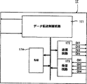
図7は図5実施例におけるコントローラ制御回路を詳細に示すブロック図であり;
図8は図7のRAMのメモリマップを示す図解図であり;
図9は図4実施例のコントローラの上から見た斜視図であり;
図10は図4実施例のコントローラの下から見た斜視図であり;
図11は実施例に利用可能なアナログジョイスティックユニットを示す斜視図であり;
図12は図11ユニットの要部を示す斜視図であり;
図13は図11ユニットの要部を示す分解斜視図であり;
図14は図11ユニットの要部を示す断面図解図であり;
図15はガイドリングによるレバーの案内状態を示す図解図であり;
図16はコントローラおよび拡張装置を詳細に示すブロック図であり;
図17はコントローラのアナログジョイスティックおよび各ボタンのデータを示す図解図であり;
図18は図5実施例のCPUの動作を示すフローチャートであり;
図19は図5実施例のバス制御回路の動作を示すフローチャートであり;
図20は図5実施例のコントローラ制御回路の動作を示すフローチャートであり;
図21は図5実施例のコントローラ回路の動作を示すフローチャートであり;
図22はコントローラ制御回路からコマンド”0”が送信されたときの制御回路の送受信データを示す図解図であり;
図23はコントローラ制御回路からコマンド”1”が送信されたときの制御回路の送受信データを示す図解図であり;
図24はコントローラ制御回路からコマンド”2”が送信されたときの制御回路の送受信データを示す図解図であり;
図25はコントローラ制御回路からコマンド”3”が送信されたときの制御回路の送受信データを示す図解図であり;
図26はコントローラ制御回路からコマンド”255”が送信されたときの制御回路の送受信データを示す図解図であり;
図27はボタンの操作によるXカウンタおよびYカウンタのリセット動作を示すフローチャートであり;
図28は電源をオンしたときのXカウンタおよびYカウンタのリセット動作を示すフローチャートであり;
図29はレバーの物理的座標とモニタの画面との関係を示す図解図であり;
図30はレバーの中心以外の位置でリセットしたときのレバーの物理的座標とモニタの画面との関係を示す図解図であり;
図31は図5実施例におけるアナログジョイスティックのデータ補正のためのタイマインタラプトルーチンの一例を示すフローチャートであり;
図32は中心補正の1つの方法を示す図解図であり;
図33はその方法を示すフローチャートであり;
図34は中心補正の他の方法を示す図解図であり;
図35はその方法を示すフローチャートであり;
図36は中心補正のさらに他の方法を示す図解図であり;
図37はその方法を示すフローチャートであり;
図38は周辺補正の1つの方法を示す図解図であり;
図39はその方法を示すフローチャートであり;
図40は周辺補正の他の方法を示す図解図であり;そして
図41はその方法を示すフローチャートである。
発明を実施するための最良の形態
以下においては、アナログジョイスティックがメモリ装置(半導体メモリ,CD−ROM等)のゲームプログラムに従ってモニタの画面上にゲームキャラクタを表示するビデオゲーム機に適用されてゲームキャラクタをコントロールするビデオゲーム機の実施例を説明する。しかしながら、この発明は、モニタに表示すべき映像の画像データをプログラムに基づいて発生する一般的な画像処理装置およびアナログジョイスティックを含む一般的な画像処理システムに適用され得ることを予め指摘しておく。
図4は、この発明に従った一実施例の画像処理装置10およびコントローラ40を示す図解図である。画像処理装置10は、その上部にカートリッジ接続用のコネクタが設けられており、そのコネクタにカートリッジ20が差し込まれている。カートリッジ20には、カートリッジ用コネクタ13と接続されることによって、画像処理装置10と電気的に接続されデータの授受が可能となるように基板が設けられている。この基板には、プログラム等のデータを記憶する外部ROMおよび必要に応じて画像処理装置10で処理されたデータを記憶するためのRAM等の読出・書込可能メモリが装着されている。また、この外部メモリのメモリマップは、図6の外部メモリ領域に示すとおり、画像処理装置10が画像信号発生させるために必要な画像データを記憶している画像データ領域201と、CPU11が所定の動作を行うために必要なプログラムデータを記憶しているプログラムデータ領域202とを含む。
画像処理装置10の前面には、コントローラ40を接続するためのコントローラ用コネクタ181−184が設けられている。このコントローラ用コネクタ181−184にコントローラ40を接続することにより、画像処理装置10は、コントローラ40と電気的に接続され、コントローラ40との間でデータの送受信が可能となる。
コントローラ40は、画像処理装置10に設けられたコントローラ用コネクタ181−184に接続するための接続用ジャック41とケーブル42で接続されている。コントローラ40は、両手または片手で把持可能な形状であり、そのハウジングの外部には、押圧することによって電気的信号を発生する複数のボタンおよび垂直に直立している操作部(アナログジョイスティックのレバー)が突出している。
画像処理装置10およびコントローラ40のハウジング内部には、電気回路および機械的機構が収容されるが、詳細は、後ほど説明する。
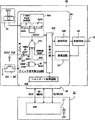
図5の詳細なブロック図を参照して、画像処理装置10本体には、カートリッジ20,モニタ30(テレビジョン受像機またはCRT等)およびコントローラ40が接続される。画像処理装置10の内部には、カートリッジ20に内蔵の外部メモリに予めストアされているプログラムに従って画像処理の進行を制御するためのCPU11が備えられている。このCPU11は、図6に示すようなメモリ空間を有し、このメモリ空間は、カートリッジ20に内蔵の外部メモリのメモリ領域201および202とW−RAM14のメモリ領域141とを含む。そして、CPU11には、バス制御回路12が接続されている。
バス制御回路12は、パラレル信号線であるバスにより、カートリッジ用コネクタ13,W−RAM14,音楽信号発生回路15,および画像信号発生回路16に接続され、シリアル信号線により、コントローラ制御回路17に接続されている。また、バス制御回路12は、CPU11からバスを介してパラレル信号で出力されたコマンドを入力し、シリアル信号に変換して、シリアル信号でコマンドをコントローラ制御回路17に出力し、かつコントローラ制御回路17から入力したシリアル信号のデータをパラレル信号に変換し、バスに出力する。バスに出力されたデータは、CPU11で処理されたり、W−RAM14に記憶される等の所定の処理を施される。
カートリッジ用コネクタ13には、カートリッジ20が接続され、カートリッジ20内の外部ROMおよび読出・書込メモリとバス制御回路12とがアドレスバスおよびデータバスで接続されデータの授受が行われる。
W−RAM14は、CPU11で処理するためのデータを一時記憶するためのメモリであって、アドレスバスおよびデータバスによってバス制御回路12と接続され、バス制御回路12を介してW−RAM14からまたはW−RAM14へデータを読み出しまたは書き込みすることができる。また、W−RAM14のメモリマップは、図6のW−RAM領域に示すとおり、コントローラデータ領域ないてコントロールパッドデータ領域141を含む。
音楽信号発生回路15は、バス制御回路12を介して、CPU11の命令に従って音楽信号を発生する回路である。
画像信号発生回路16は、バス制御回路12を介して、CPU11の命令に従って画像信号を発生する回路である。
コントローラ制御回路17は、バス制御回路12およびコントローラ用コネクタ181−184にシリアルでデータを送受信できるように接続されている。
コントローラ制御回路17の具体的な構造を図7の内部ブロック図を参照して説明する。
データ転送制御回路171は、パラレル−シリアル変換回路とシリアル−パラレル変換回路とを含み、シリアル−パラレル変換回路によって、バス制御回路12からのシリアルデータを受信し、かつパラレル−シリアル変換回路43によって、バス制御回路12へシリアルデータを送信する。また、データ転送制御回路171は、送信回路172,受信回路173およびRAM174にバスによって接続されている。そのため、データ転送制御回路171は、RAM174に対してデータをパラレルデータとして送受信する。従って、データ転送制御回路171は、バス制御回路12からの命令に基づいて、RAM174のデータを読出してバス制御回路12に送信したり、バス制御回路12から受信したデータをRAMに書き込む。
送信回路172は、バスからのパラレル信号をシリアル信号に変換してデータを送信する。信号線CH1−CH4は、それそれコントローラ用コネクタ181−184に接続され、それぞれに接続されたコントローラ40にシリアルデータを送信する。
受信回路173は、コントローラ40からのシリアル信号を受信し、受信したデータをパラレル信号としてバスに出力する。信号線CH1−CH4は、それぞれコントローラ用コネクタ181−184に接続され、それぞれに接続されたコントローラ40からシリアルデータを受信する。
RAM174は、データ転送制御回路171とバスで接続されており、データをパラレル信号で入出力できる。RAM174に記憶されているデータは、図8のメモリマップを用いて説明する。エリア1741には、1チャンネル用のコマンドが記憶される。エリア1742には、1チャンネル用の送信データおよび受信データが記憶される。エリア1743には、2チャンネル用のコマンドが記憶される。エリア1744には、2チャンネル用の送信データおよび受信データが記憶される。エリア1745には、3チャンネル用のコマンドが記憶される。エリア1746には、3チャンネル用の送信データおよび受信データが記憶される。エリア1747には、4チャンネル用のコマンドが記憶される。エリア1748には、4チャンネル用の送信データおよび受信データが記憶される。
上述のようなブロック構成により、データ転送制御回路171は、送信回路172から所定のコマンド(命令)を送信したり、受信回路173が受信したデータをRAM174に記憶したりすることができる。
コントローラ用コネクタ181−184は、それぞれコントローラ制御回路17にシリアル線で接続されており、かつコントローラ40の接続用ジャック41と着脱自在に接続されている。また、コントローラ用コネクタ181−184がコントローラ40の接続用ジャック41に接続されたとき、コントローラ40とコントローラ用コネクタ181−184とが電気的に接続され、その間でデータの授受ができるようになる。
図9および図10を参照して、この実施例におけるコントローラ40は、上ハーフと下ハーフとからなるハウジング401を含み、ハウジング401の左右両端には、左側グリップ402Lと右側グリップ402Rが手前側に突出して形成される。左側グリップ402Lと右側グリップ402Rの中間位置には、中央グリップ402Cが手前側に突出して形成される。左側グリップ402Lの基端近傍のハウジング401表面には、ディジタルジョイスティックである十字方向指示スイッチ403が形成される。右側グリップ402Rの基端近傍のハウジング401表面には、6種類の動作を指示する動作指示スイッチ404A,404B,404C,404D,404Eおよび404Fがそれぞれ形成される。
中央グリップ402Cの基端近傍のハウジング401上には、360°の全方向を指示可能なアナログジョイスティック45が形成される。ハウジング401のほば中央位置には、ゲームのスタートを指示するスタートスイッチ405が形成される。また、スタートスイッチ405は、スイッチ403および404Aないし404F,およびアナログジョイスティック45によって囲まれる領域のほぼ中央に位置する。
さらに、ハウジング401の背面側に一対の側面スイッチ406Lおよび406Rが形成され、下ハーフのほぼ中央であって、中央グリップ402Cの基端近傍に底面スイッチ407が形成される。
下ハーフの背面側は底面方向に延長され、その先端には開口部408が形成されている。開口部408の奥には図4に示す拡張カートリッジ50がそこに接統されるコネクタ(図示せず)が設けられている。また、開口部408に挿入されたカートリッジ50を排出するためのレバー409が開口部408に形成されている。そして、上述の拡張カートリッジ50を挿入する開口部408のレバー409の反対側には、切欠410が形成され、この切欠410はレバー409を用いて拡張カートリッジ50を取り出すときに拡張カートリッジ50を引き出すためのスペースを形成する。
ここで、図11ないし図15を参照して、アナログジョイスティック45を詳細に説明する。アナログジョイスティック45は、図11に示すジョイスティックユニットとして構成される。そのジョイスティックユニットはハウジング401の上ハーフおよび下ハーフで挟持される。ジョイスティックユニットは、ケース451とカバー452とによって形成されるハウジングを含み、ハウジング内には内ケース453が収容される。
図12および図13に示すように、内ケース453は中央部に碗形の凹部454を有し、この凹部454の周囲に2対の支持プレート455aおよび455b,および456aおよび456bが互いに90°の角度間隔を隔てて設けられ、それらの支持プレート455aおよび455b,および456aおよび456bのそれぞれに半円形の軸受457aおよび457b,および458aおよび458bが設けられている。軸受457aおよび457b,または458aおよび458bは、同一軸線上に配置されており、軸受457aおよび457b,および458aおよび458bの軸心は同じ高さレベルで互いに直交している。また、内ケース453の側面には回転軸心が互いに直交する羽根車ないし円盤459および460が回転自在に支持され、それぞれの円盤459および460には歯車461が付設されている。
アナログジョイスティックユニットは、さらに揺動部材462および463を含む。一方の揺動部材462は長手方向に長い長孔464を備える円弧状部材でなり、その両端部に支軸465aおよび465bが設けられていると共に、それらの支軸465aおよび465bから、平坦面466aおよび466bを備えた軸端部467aおよび467bが延出され、片側の軸端部467bに扇形の歯車468が設けられている。他方の揺動部材463は、一方の揺動部材462よりも曲率半径の小さな円弧状部材によって構成されている点で一方の揺動部材462と異なっているが、その他の点では、略同様の構成になっている。すなわち、参照番号469が長孔、参照番号470aおよび470bは支軸、参照番号471aおよび471bは平坦面、参照番号472aおよび472bは軸端部、そして参照番号473が歯車を示す。
一対の揺動部材462および463は、それらの支軸465aおよび465b,および470aおよび470bを内ケース453の2組の軸受457aおよび457b,および458aおよび458bに各別に嵌め込んで揺動自在に支持させることによって、長孔463および469の長手方向が互いに直交するように間隔を隔てて重なった状態に配置される。こうして内ケース453に取り付けられた一対の揺動部材462および463において、扇形の歯車468および473は、上述の歯車461に噛み合わされる。また、上述の平坦面466aおよび466b,および471aおよび471bのそれぞれは、後述するレバー474の中立状態において同一水平面に含まれる。
図13に示すように、レバー474は、一端部に径外方向に突き出た突起475を備え、中間部に球部476を備え、他端部に連結部477を備えている。上記球部476には180°隔てた箇所に緯線方向に延びる溝478が形成されている。また、レバー474の直径は揺動部材462および463の長孔464および469の短径寸法よりも大きくない寸法、好ましくは長孔464および469にがたつきなく摺動可能に嵌入され得る寸法に選ばれる。そして、レバー474の一端部が長孔464および469に貫挿され、かつその突起475が一方の揺動部材462の長孔464に嵌まり込んでいる。このため、このレバー474において、突起475は内ケース453に取り付けられた上側の揺動部材463の長孔469の長手方向に直交する方向に突出することになり、これによって、レバー474が上方に引っ張られたときには、突起475が上側の揺動部材463によって抜止めされる。
図12のように組み立てられた横構部分が、図11に示した外ケースに収容される。このとき、内ケース453は図示していないビスなどの適宜手段で外ケースに固定される。
そして、内ケース453には図13からよくわかるように、2つの羽根車ないし円盤459および460に対し、それぞれ、フォトインタラプタ479および480が対向して設けられる。このフォトインタラプタ479および480はそれぞれ発光素子および受光素子(図示せず)を含み、発光素子からの光が羽根車ないし円盤459および460にそれぞれ形成されたスリット481および483を通過して受光素子によって受光される。したがって、フォトインタラプタ479および480は、それぞれスリット481および482を検出し、スリット481および482に応じて、羽根車ないし円盤459および460の回転に従ったパルス信号を出力する。
なお、揺動部材462および463の揺動軸心(支軸465および470)の高さレベルとレバー474の球部476の中心の高さレベルとは一致している。また、外ケース451にはフレキシブル配線板483を接続した基板(図示せず)が組み込まれており、この基板の配線パターンに上述のフォトインタラプタ479および480に含まれる発光素子や受光素子が電気的に接続されている。
図14から判るように、一対の揺動部材462および463に備わっている平坦面466および471の上に溝付きリング484が載架せられ、この溝付きリング484の上にコイルばね485が配置される。溝付きリング484は押下げ部材の例示であって、レバー474の中立状態においては、リング484の下面が水平になり、そのリング484の下面と上述の平坦面466および471とが互いに面接触して重なり合う。
図14に示すように、カバー452にはガイドリング486が取り付けられていて、このガイドリング486の中央部に円形の孔487が形成される。ガイドリング486は、さらに、孔487の周囲から外方に向かって上がり勾配となるガイド壁488を含む。つまり、ガイド壁488は全体として“すりばち”または“コーン”形状に形成される。そして、ガイド壁488は、上から見たとき、図15に示すように8角形になる外縁491を有する。
なお、孔487の直径は上述のレバー474の球部476の外周直径と略同じ寸法に選ばれる。したがって、図14に示すように、孔487の孔縁がレバー474の球部476に接触し、レバー474が球部476と孔487とによって全方位揺動自在に支持されるようになっている。また、ガイドリング486の孔487には、180°隔てた2箇所に円形のボス489が径内方向に向けて突出されており、これらのボス489が、上記球部476に設けられている緯線方向の溝478に各別に嵌まり込んでいる。したがって、レバー474はボス489の軸心回りに揺動することができるが、レバー474自体の軸心まわりには回転することができない。したがって、球部476の溝478とボス489とによってレバー474がその軸心回りに回転することを阻止する。
また、カバー452を外ケース451に被着した状態では、ばね490が溝付きリング484とカバー452との間に挟まれて圧縮している。そのため、一対の揺動部材462および463の平坦面466および471は溝付きリング484を介してばね490の力で常時押圧されており、この押圧作用によって、一対の揺動部材462および463がいずれの方向にも傾かない姿勢になるように常時弾発付勢され、その結果、レバー474が垂直姿勢、すなわち中立状態に常時弾発付勢された状態になる。
レバー474には、操作つまみ492がレバー474の連結部477を介して取り付けられる。操作つまみ492の上面には、手の指を置きやすいように凹所493が備わっている。
このようなアナログジョイスティックユニットにおいて、レバー474の傾斜方向および傾斜角度に応じて、揺動部材462および/または463が揺動し、揺動部材462および/または463の揺動角度に応じて羽根車ないし円盤469および/または470が回転すると、それらの円盤469および/または470の回転量に応じたパルスがフォトインタラプタ479および480から出力され、そのパルスがX軸および/またはY軸の方向での座標信号として利用される。
ここで、ガイドリング486について説明する。ガイドリング486は、図15に示すように上から見たとき8角形の外縁491を有するガイド壁488を含む。8角形の外縁491のそれぞれの角が図15に示すようにレバー474を受け入れる凹所として機能し、角と角との間の直線(辺)がレバー474を案内するガイドとして働く。そのため、この実施例では、それぞれの角を上(北),下(南),左(西),右(東),上と左との中間(北西),上と右との中間(北東),下と左との中間(南西)および下と右との中間(南東)の8つの位置(45°間隔)に位置決めする。
図15に示す上(北)を示すポイントNについてみると、このポイントNを挟む両側のガイド壁488aおよび488bは、ポイントNに向かって収束している。すなわち、両側のガイド壁488aおよび488bは互いに交差し、その交差した位置がポイントNである。そのため、このポイントNに向けてレバー474を倒すと、レバー474は、ポイントNを挟む両側のガイド壁488aおよび488bに沿って移動し、すなわち、ガイド壁488aおよび488bによってガイドされて、最終的に、ポイントNに位置決めされる。したがって、たとえばモニタ(図示せず)上の可動キャラクタ(図示せず)をモニタ画面上において上方向に移動させようとするとき、つまり、可動キャラクタをその可動キャラクタからみて直進方向に移動させようとするとき、レバー474をポイントNに向けて倒すだけでよい。つまり、可動キャラクタをまっすぐ前進させるとき、レバー474をポイントNの近傍に向けて傾けると、レバー474はポイントNに隣接するガイド壁488aおよび488bに沿ってポイントNで拘束されるので、その状態を保持するだけで、可動キャラクタ正確に直進させることができる。
また、円盤459および460の回転を検出する方法としてスリット481および482をフォトインタラプタ479および480で検出する例を挙げたが、他の方法が利用されてもよい。たとえば、円盤459および460にそれぞれ複数の導電部材を設け、その導電部材を電気的に検出することによって、円盤459および460の回転を検出する方法が利用可能である。
次に、コネクタ181に接続されるコントローラ40を図16の詳細なブロック図を用いて説明する。
前述のコントローラ用コネクタ182−184に接続されるコントローラ40は、コントローラ用コネクタ181に接続されているコントローラ40と同じものである。そのため、説明は省略する。
接続用ジャック41は、コントローラ用コネクタ181−184と接続され、画像処理装置10から送信されたデータを変換回路43に出力する。
変換回路43は、画像処理装置10のコントローラ制御回路17のデータをシリアル信号でケーブル42を介して送受信する。具体的に述べると、変換回路43は、コントローラ制御回路17から受信したシリアルデータをコントローラ回路44内の受信回路441へシリアル信号で送信するとともに、コントローラ回路44内の送信回路445からのシリアル信号を受信し、シリアル信号として、ケーブル42を介してコントローラ制御回路17へ出力する。
コントローラ回路44は、受信回路441,制御回路442,スイッチ信号検出回路443,カウンタ444,送信回路445およびジョイポート制御回路446を含む。送信回路445は、制御回路442から出力されたパラレル信号をシリアル信号に変換して変換回路43へ出力する。受信回路441は、変換回路43から出力されたシリアル信号をパラレル信号に変換して制御回路442に出力する。
制御回路442は、受信回路441からのパラレル信号が入力されることにより、画像処理装置10から出力されたデータを受け取る。制御回路442は、その受信したデータをもとに所定の動作を行う。制御回路442は、スイッチ信号検出回路443にスイッチ信号を検出するように指示し、スイッチ信号検出回路443からどのボタンが押されているかを表わすデータを受け取る。また、制御回路442は、カウンタ444にデータの出力を指示し、Xカウンタ444XおよびYカウンタ444Yのデータを受け取る。制御回路442は、ジョイポート制御回路446とアドレスバスおよびデータバスで接続されており、ジョイポート制御回路446に命令データを出力することにより拡張装置50を制御することができ、拡張装置50から出力されたデータを受け取ることができる。
スイッチ信号検出回路443は、ボタン403−407のスイッチ信号を入力し、所定の復数のボタンが同時に押されたことを検出し、リセット信号をリセット回路448に送信する。また、スイッチ信号検出回路443は、スイッチ信号を制御回路442へ出力する。
カウンタ回路444は、2つのカウンタを含む。一方は、Xカウンタ444Xであり、ジョイステック45内のX軸用フォトインタラプタ479から出力される検出信号(パルス信号)を計数(カウント)するものである。これによって、レバー474がX軸方向にどれだけ傾いたかを検出することができる。他方は、Yカウンタ444Yであり、ジョイスティック45内のY軸用フォトインタラプタ480から出力されるパルス信号をカウントするものである。これによって、操作部がY軸方向にどれだけ傾いたかを検出することができる。カウンタ回路444は、これらXカウンタ444XおよびYカウンタ444Yによって計数された計数値を制御回路442の指示に従って、制御回路442へ出力する。
ジョイポート制御回路446は、制御回路442およびジョイポートコネクタ46を介して拡張装置50にアドレスバスおよびデータバスで接続されている。これによって、制御回路442と拡張装置50とがアドレスバスおよびデータバスで接続されることになり、画像処理装置10のメインCPU11の命令に従って拡張装置50を制御可能となる。
ボタン403−407は、コントローラ40の外部に突出したキートップを使用者が押圧することにより、電気的信号を発生するものである。この実施例では、キーが押されたとき、電圧がハイからローに変わる。この電圧の変化は、スイッチ信号検出回路443によって検出される。
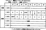
図17を用いて、コントローラ10のデータを説明する。コントローラ10で発生するデータは、4バイトであり、B,A,G,START,上,下,左,右,JSRST,0(実施例では使用しない。),L,R,E,D,C,F,X座標およびY座標からなり、それぞれのビットは、0か1で表される。Bは、ボタン404Bに対応しており、ボタン404Bが操作者によって押されたとき1になり、押されていないとき0になる。同様に、Aはボタン404A,Gはボタン407,STARTはボタン405,上と下と左と右とはボタン403,Lはボタン406L,Rはボタン406R,Eはボタン404E,Dはボタン404D,Cはボタン404C,Fはボタン404Fに対応する。JSRSTは、ボタン405とボタン406Lとボタン406Rとが操作者によって同時に押されたとき1になり、押されていないとき0になる。X座標およびY座標は、それぞれXカウンタ444XおよびYカウンタ444Yの計数値のデータである。
次に、拡張装置50について説明する。図16の拡張装置50の例は、バックアップメモリカード50である。このバックアップメモリカード50には、アドレスを指定することにより所望のアドレスにデータを書込・読出可能なRAM51とそのRAM51のデータを保存するために必要なバックアップ電源を供給するための電池52が内蔵されている。そして、このバックアップメモリカード50をコントローラ40のジョイポートコネクタ46に接続することにより、RAM51は、ジョイポート制御回路446と電気的に接続されるため、データの送受信が可能になる。このデータの送受信については、後ほど詳しく説明する。
上述の実施例では、拡張装置の例として、バックアップメモリカード50を示したが、拡張装置としては、この実施例に限定されるものではなく、データを送信することができおよび/またはデータを受信して動作することができるなら任意の装置が適用可能である。
次に画像処理装置10とコントローラ40とのデータの送受信に関する動作説明をする。
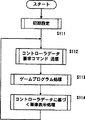
まず、図18の画像処理装置10のCPU11のフローチャートを参照して画像処理に関する説明を行う。ステップS111で、CPU11は、図5のプログラムデータ領域202に記憶されている初期値(図示せず)に基づき、初期設定を行う。次に、ステップS112で、CPU11は、プログラムデータ領域202に記憶されているコントールパッドデータ要求コマンドをバス制御回路12に出力する。次に、ステップS113で、CPU11は、図5のプログラムデータ領域202に記憶されているプログラムにおよび画像データ領域201に基づき所定の画像処理を行う。また、CPU11がステップS113を実行しているときに、バス制御回路12は、ステップS121−124を実行している。次に、ステップS114で、CPU11は、図3のコントロールパッドデータ領域141に記憶されているコントロールパッドデータに基づき画像データを出力する。ステツプ114を終了した後は、CPU11は、ステップS112−ステップS114を繰り返し実行する。
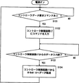
バス制御回路12の動作を図19を用いて説明する。ステツプ121で、バス制御回路12は、CPU11がコントローラデータ要求コマンド(コントローラ40のスイッチデータまたは拡張装置50のデータ等の要求命令)を出力したか否かを判断する。コントローラデータ要求コマンドが出力されていなければ、出力されるまで待機する。コントローラデータ要求コマンドが出力されていれば、ステップS122に移る。ステップS122で、バス制御回路12は、コントローラ制御回路17にコントローラ40のデータを読み込むためのコマンド(後に示すコマンド1またはコマンド2等)を出力する。次に、ステップS123で、バス制御回路12は、コントローラ制御回路17がコントローラ40からデータを受信してRAM174に記憶したか否かを判断する。バス制御回路12は、コントローラ制御回路17がコントローラ40からデータを受信してRAM174に記憶していなければ、ステップS123で待機し、コントローラ制御回路17がコントローラ40からデータを受信してRAM174に記憶していれば、ステップS124に移る。ステップS124で、バス制御回路12は、コントローラ制御回路17のRAM174に記憶されているコントローラ40のデータをW−RAM14へ転送する。バス制御回路12は、W−RAM14へのデータ転送が終わるとステップS121に戻り、ステップS121−ステップS124の動作を繰り返す。
なお、図18および図19のフローチャートでは、バス制御回路12がRAM174からW−RAM14へデータを転送した後、CPU11がW−RAM14に記憶されたデータを処理する例を示したが、CPU11がバス制御回路12を介して直接RAM174のデータを処理してもよい。
次に、図20のコントローラ制御回路17の動作フローチャートを参照して、データ転送に関する動作説明を行う。
ステップS171で、バス制御回路12からの書き込み待ちが有るか否かを判断する。バス制御回路12からの書き込み待ちがなければ、データ転送制御回路171は、バス制御回路12からの書き込み待ちが有るまで待機する。バス制御回路12からの書き込み待ちが有れば、次のステップS172に移る。ステップS172で、データ転送制御回路171は、1−4チャンネルに対するコマンドおよび/またはデータをRAM174に記憶させる。
ステップS173において1チャンネル目のコマンドおよび/またはデータをコネクタ181に接続されているコントローラ40に送信する。コントローラ40の制御回路442は、このコマンドおよび/またはデータに基づいて所定の動作を行い、画像処理装置10に送信すべきデータを出力する。このデータの内容は、後の制御回路442の動作説明で詳しく説明する。次に、ステップS174で、データ転送制御回路171は、この制御回路442から出力されたデータを受信し、そのデータをRAMに記憶する。
ステップS175において2チャンネル目のコマンドおよび/またはデータをコネクタ182に接続されているコントローラ40に送信する。コントローラ40の制御回路442は、このコマンドおよび/またはデータに基づいて所定の動作を行い、画像処理装置10に送信すべきデータを出力する。次のステップS176は、ステップS174と同様である。
ステップS177において3チャンネル目のコマンドおよび/またはデータをコネクタ183に接続されているコントローラ40に送信する。コントローラ40の制御回路442は、このコマンドおよび/またはデータに基づいて所定の動作を行い、画像処理装置10に送信すべきデータを出力する。次のステップS178は、ステップS174と同様である。
ステップS179において4チャンネル目のコマンドおよび/またはデータをコネクタ184に接続されているコントローラ40に送信する。コントローラ40の制御回路442は、このコマンドおよび/またはデータに基づいて所定の動作を行い、画像処理装置10に送信すべきデータを出力する。次のステップS180は、ステップS174と同様である。
ステップS181で、データ転送制御回路171は、ステップS174,176,178および180で受信したデータをまとめて、バス制御回路12へ転送する。
次に、図21のコントローラ40内のコントローラ回路44の動作フローチャートを示す。まず、ステップS402では、コマンドが画像処理装置10から制御回路442に入力されているか否かを判断する。コマンドが入力されていなければ、制御回路442は、コマンドが入力されるまで待機する。コマンドが入力されていれば次のステップSに移る。ステップS404では、コマンドが入力されると、制御回路442に入力されたコマンドがステータス要求コマンド(コマンド0)であるか否かを判断する。コマンド0でなかった場合は、ステップS408に移る。コマンド0であった場合は、ステップS406に移り、ステータス送出処理を行う。具体的には、CPU11がコマンド0を出力した場合の画像処理装置10とコントローラ40との送受信データを詳細に表した図22を参照して説明する。
コントローラ40の制御回路442は、1バイト(8ビット)で構成されるコマンド0のデータを受信すると、TYPE L(1バイト),TYPE H(1バイト)およびステータスを送信する。TYPE LおよびTYPE Hは、ジョイポートコネクタ46に接続されている機器がどんな機能を持っているかを示すためのものであり、拡張装置50に記録されているデータである。これによって、画像処理装置10は、コントローラ40にどの様な拡張装置50が接続されているかを認識することが可能である。ステータスは、ジョイポートに拡張装置50が接続されているか否か、およびリセット後に拡張装置50が接続されたか否かを示すデータである。
ステップS408では、入力されたコマンドがパッドデータ要求コマンド(コマンド1)であるか否かを判断する。コマンド1でなかった場合は、ステップS412に移る。コマンド1であった場合は、ステップS410に移り、パッドデータ送出処理を行う。具体的には、CPU11がコマンド1を出力した場合の画像処理装置10とコントローラ40との送受信データを詳細に表した図23を参照して説明する。
コントローラ40の制御回路442は、1バイト(8ビット)で構成されるコマンド1のデータを受信すると、B,A,G,START,上,下,左,右,L,R,E,D,C,Fの14個のスイッチのデータ(16ビット)とJSRST(1ビット)とカウンタ444Xおよびカウンタ444Yのデータ(16ビット)を送信する。これらのデータを画像処理装置10に送信することによって、操作者がどのようにコントローラ40を操作したかを画像処理装置10に認識させることができる。
ステップS412では、入力されたコマンドが拡張コネクタ書き出し要求コマンド(コマンド2)であるか否かを判断する。コマンド2でなかった場合は、ステップS416に移る。コマンド2であった場合は、ステップS414に移り、拡張コネクタ書き出し処理を行う。具体的には、CPU11がコマンド2を出力した場合の画像処理装置10とコントローラ40との送受信データを詳細に表した図24を参照して説明する。
コントローラ40の制御回路442は、1バイト(8ビット)で構成されるコマンド2のデータ,アドレスの上位ビットを示すアドレスH(8ビット),アドレスの下位ビット(3ビット)を表わすアドレスLおよび送受信のアドレスデータエラーをチェックするためのアドレスCRC(5ビット)を受信すると、受信したアドレスデータに基づいて、拡張装置50に記憶されているデータ(32バイト)およびデータエラーをチェックするためのCRC(8ビット)を送信する。このように、拡張装置50と画像処理装置10とが接続されることにより、画像処理装置10が拡張装置50からのデータを処理することができる。
ステップS416では、入力されたコマンドが拡張コネクタ読み込み要求コマンド(コマンド3)であるか否かを判断する。コマンド3でなかった場合は、ステップS420に移る。コマンド3であった場合は、ステップS418に移り、拡張コネクタ読み込み処理を行う。具体的には、CPU11がコマンド3を出力した場合の画像処理装置10とコントローラ40との送受信データを詳細に表した図25を参照して説明する。
コントローラ40の制御回路442は、1バイト(8ビット)で構成されるコマンド3のデータ,アドレスの上位ビットを示すアドレスH(8ビット),アドレスの下位ビット(3ビット)を表わすアドレスL,送受信のアドレスデータエラーをチェックするためのアドレスCRC(5ビット)および拡張装置50に送るべきデータ(32バイト)を受信すると、受信したデータに対してエラーをチェックするためのCRC(8ビット)を送信する。このように、拡張装置50と画像処理装置10とが接続されることにより、画像処理装置10が拡張装置50を制御可能となる。また、このように、拡張装置50と画像処理装置10とが接続されることにより、コントローラ40の機能を飛躍的に向上させることができる。
ステップS420では、入力されたコマンドがリセットコマンド(コマンド255)であるか否かを判断する。コマンド255でなかった場合は、ステップS402に移る。コマンド255であった場合は、ステップS422に移り、ジョイスティックカウンタリセット処理を行う。具体的には、CPU11がコマンド255を出力した場合の画像処理装置10とコントローラ40との送受信データを詳細に表した図26を参照して説明する。
コントローラ40の制御回路442は、1バイト(8ビット)で構成されるコマンド255のデータを受信すると、リセット信号を出力し、Xカウンタ444XおよびYカウンタ444Yをリセットし、前述のTYPE L(1バイト),TYPE H(1バイト)およびステータスを送信する。
上述した、ジョイスティック45のリセットに関する詳細な説明をする。
ジョイスティック45の原点を決定するリセットの方法は、ボタンの操作によるリセット,電源のON−OFFによるリセットおよび画像処理装置10によるリセットの3つの方法がある。
(1)ボタンの操作によるリセット
図27のフローチャートを参照して、ジョイスティック45の傾斜状態のデータを記憶しているカウンタ444のリセットについて説明する。まず、ステップS432で、スイッチ信号検出回路443が、ボタン406L,ボタン406Rおよびボタン405が同時に押されたか否かを検出する。そして、3つのボタンが押されていないときは、引き続きスイッチ信号の検出を続行する。また、3つのボタンが押された場合は、リセット信号を出力する。
このリセット信号が出力されたことによって、ステップS434で、Xカウンタ444XおよびYカウンタ444Yの計数値がリセットされる。したがって、ボタン406L,ボタン406Rおよびボタン405が同時に押される毎に、ジョイスティックの原点が決定される。
この実施例では、使用者がボタン406L,ボタン406Rおよびボタン405の3つを同時に押したとき、スイッチ信号検出回路443がリセット信号を発生する例を示したが、特にこの3つのボタンでなくともよい。例えば、使用者が押すボタンは、3つに限定されるものではなく2つでも4つでもよい。また、リセットのためのボタンは、上述の3つのボタンでなくとも、その他に設けられたボタンのうちどのボタンを設定してもよい。
(2)電源のオン−オフによるリセット
図28のフローチャートを参照して、その他のカウンタ444のリセットについて説明する。まず、コントローラ40が画像処理装置10に接続されている場合は、使用者が画像処理装置10の電源スイッチをONするか、コントローラ40が画像処理装置10に未接続の場合は、使用者がコントローラ40の接続用ジャックを画像処理装置10のコントローラ用コネクタ181−184に差込むことにより、コントローラ40に電源を供給することに応じて、パワーオンリセット回路447がリセット信号を出力する。このリセット信号が出力されたことによって、ステップS442で、Xカウンタ444XおよびYカウンタ444Yの計数値がリセットされる。したがって、電源がコントローラ40に供給される毎にジョイスティックの原点が決定される。
(3)画像処理装置10によるリセット
前述の図21のステップS420およびステップS422のリセットがある。このリセットによって、画像処理装置10の処理状況に応じて、プログラムで自由にジョイスティック45の原点を決定可能である。
以上の方法でXカウンタ444XおよびYカウンタ444Yをリセットすることができる。レバー474が中立しているとき(使用者に操作されていないとき)にリセット信号が出力されることにより、Xカウンタ444XおよびYカウンタ444Yに間違った計数値が記憶されたままで、画像処理装置10に間違った計数値を送信することを防止できる。
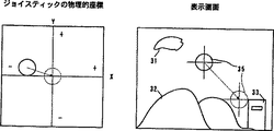
次に、コントローラ40によって画面を変化させる例を図29を用いて説明する。図29の左図は、レバー474の物理的な傾斜量を座標で表したものである。具体的に説明すると、中心に描かれている丸がレバー474の位置を表し、この図では、操作者が操作しない状態(レバー474がハウジングに対して、垂直に直立した状態)を表している。もし、操作者から見て、レバー474を前方に傾斜させたときは、丸がY軸に対して+方向に移動し、レバー474を後方に傾斜させたときは、丸がY軸に対して−方向に移動する。また、操作者から見で、レバー474を右方に傾斜させたときは、丸がX軸に対して+方向に移動し、レバー474を左方に傾斜させたときは、丸がX軸に対して−方向に移動する。
図29の右図は、実施例の一例として、レバー474を前後左右に傾斜させることにより、照準35を上下左右に動かし、敵34に照準を合わせるゲームの表示画面を示している。雲31,山32および建物33は、スクロール等で変化する背景画像であり、敵34は画面上を自由に動き回るオブジェクトである。例えば、図に示すように敵34が画面の右上に現れているとき、操作者は、レバー474を右に傾け、かつ前方に傾ける。すると、コントローラ40内にあるXカウンタ444Xが加算され計数値が大きくなり、かつYカウンタ444Yが加算され計数値が大きくなる。この計数値のデータは、画像処理装置10に送信される。画像処理装置10は、この加算値のデータを用いて、照準35の表示位置を変化させる。その結果、照準35と敵34とが重なり合うようになる。そして、重なったとき、ボタン404A等のボタンを押すと、このスイッチデータも前述の加算値のデータと同様に画像処理装置10に送信される。その結果、画像処理装置10は、ミサイル(図示せず)等を画面に表示し、敵34に当たるように表示するための画像信号を発生する。
次に、レバー474を中心部よりずらして(傾斜して)リセットした場合の例を図30を用いて説明する。図30の左図の実線の丸で示した座標位置でXカウンタ444XおよびYカウンタ444Yをリセットしたとき、操作者がレバー474から手を放すと、レバー474は、座標の中心位置(破線の丸で示した位置)に復帰する。このときの画像表示の変化を図30の右図を用いて説明する。まず、Xカウンタ444XおよびYカウンタ444Yをリセットしたときは、図29の右図と同じように、照準35が実線の丸の位置に表示されている。なぜなら、Xカウンタ444XおよびYカウンタ444Yの計数値が0であるので、初期値と同じ計数値であるからである。次に、操作者がレバー474から手を放し、レバー474が座標の中心位置に復帰したとき、コントローラ40内にあるXカウンタ444Xが加算され計数値が大きくなり、かつYカウンタ444Yが減算され計数値が小さくなる。この計数値のデータは、画像処理装置10に送信される。画像処理装置10は、この加算値のデータを用いて、照準35の表示位置を変化させる。(破線の照準35の位置に変化させる。)
このようなリセットをどの様なときに行うのかを説明する。例えば、操作者が敵34の出現する位置を図30の右図の破線の照準35の位置であると予想したとする。その場合、敵34が出現した瞬間に破線の照準35の位置に照準35を合わせたいと考える。しかし、破線の照準35に照準35を静止し続けるのでは、ゲームを操作するものとして退屈であり、かつ予想以外の場所から敵34が出現したとき対応できない可能性がある。そのため、敵34が出現した瞬間に破線の照準35の位置に照準35を合わせ、かつ自由に他の場所に照準35を移動させるようにするために上述のリセット機能を用いる。操作者の動作を具体的に説明すると、まず操作者は、実線の照準35を基準に、敵34が現れると予想した位置(破線の照準35の位置)と対象の位置に照準35が表示されるようにレバー474を傾斜させる。そのとき、レバー474の物理的座標は、図30の左図の実線の丸の位置になる。このとき、操作者は、ボタン406L,ボタン406Rおよびボタン405の3つを同時に押す。すると、Xカウンタ444XおよびYカウンタ444Yがリセットされ、照準35は、実線の照準35の位置に表示される。そして、操作者は、自由に照準35を動かし、敵34の出現を待つ。もし、破線の照準35の位置に敵34が出現したとき、操作者は、レバー474から手を放す。すると、レバー474は、図30の左図の破線の丸の物理的座標位置に復帰する。その結果、照準35は、破線の照準35の位置に表示される。操作者は、照準35を敵34に正確に重ね合せ、ボタン404A等のスイッチを押すと、ミサイル(図示せず)等が画面に表示され、敵34に当たる。
また、上述のようにリセットを行うと、レバー474を右下方向に多く動かすことができる。そのため、操作者が、レバー474を右下方向に多く動かしたいときに有効である。
次に、この発明の特徴となるアナログジョイスティック45のデータを補正する方法について説明する。アナログジョイスティックのデータを補正する理由は、1つはレバー474のニュートラル状態におけるデータのずれが生じるからであり、1つはレバー474の傾動範囲を変更する必要性があるからである。
アナログジョイスティック45からのデータを補正するために、図16に示す制御回路442において、図31に示すタイマインタラプトルーチンが実行される。このタイマインタラプトルーチンはたとえば1/30秒程度の一定時間毎に実行される。
図31の最初のステップS1では、制御回路442は、Xカウンタ444XおよびYカウンタ444Yから、Xカウント値およびYカウント値、すなわち、レバー474の実際の傾斜方向および傾斜量を示す座標データXaおよびYaを読み取る。このデータXaおよびYaは、制御回路442に含まれるメモリ(図示せず)にストアされる。続くステップS2では、制御回路442は、中心補正を実行する。中心補正とは、アナログジョイスティック45のレバー474のニュートラル位置におけるデータXaおよびYaの”0”からのずれを補正することである。つまり、操作者がレバー474の操作を開放したとき、レバー474はニュートラル位置になり、そのとき、データXaおよびYaはともに”0”となるはずである。ところが、アナログジョイスティック45の内部機構における摩擦のために、レバー474のニュートラル位置においてXカウンタ444XおよびYカウンタ444YのデータXaおよびYaが”0”に戻らないことがある。このようなニュートラル位置におけるデータのずれをステップS2によって補正する。中心補正の方法は、後に詳しく説明するように、図32,図34および図36に示す3つの方法がある。
ステップS2の中心補正が終了すると、次のステップS3において、制御回路442は、そのとき設定されている周辺補正モードが”円モード”かどうか判断する。上述の実施例においては、アナログジョイスティック45のガイドリング486は8角形の外縁491を有し、したがって、レバー474はこのガイドリング486の外縁491によって、8角形の範囲で傾動可能である。しかしながら、ゲームの内容によっては、8角形の範囲ではなく、円形や4角形の範囲でレバーが傾動されたものとみなすことが要求されることがある。レバー474の実質的傾動範囲が図38に示すように円形の場合を”円モード”とよび、レバーの実質的傾動範囲が図40に示すように4角形の場合を”4角形モード”とよぶ。前者の場合、レバー474は実際には8角形の外縁491で規制されて8角形の範囲で傾動されるが、ステップS4において、そのレバー474の動きを図38に示す円形の範囲に補正する。後者の場合、ステップS5において、そのレバー474の動きを図40に示す4角形の範囲に補正する。”円モード”はレバー474を最大傾動させたときに、レバー474の傾斜方向によってジョイスティックデータが変わらない方がよいゲーム、たとえばレバーを傾動させた方向および量によって可動キャラクタをモード画面上で全方向に移動させるゲームに好適する。”4角形モード”は、先に述べたレーシングゲームのように、レバー474を前方または後方に最大傾動した状態でレバー474を左右に傾動させるゲームに好適する。
次に、図32および図33を参照して、第1の中心補正方法について説明する。図32に示す方法は、Xカウンタ444XおよびYカウンタ444YのデータXaおよびYaがそれぞれ図32における斜線で規定される所定範囲内にあるとき、アナログジョイスティック45から出力されるデータ(以下、”ジョイスティックデータ”と呼ぶ)XおよびYをそれぞれ”0”とみなす方法である。具体的には、カウンタデータXaが”+16”から”−16”の範囲にあるとき、ジョイスティックデータXは”0”として出力される。同様に、カウンタデータYaが”+16”から”−16”の範囲にあるとき、ジョイスティックデータYは”0”として出力される。なお、この具体的数値”16”および”−16”は発明者等の実験によって決定された数値であるが、他の任意の数値を設定することができることはいうまでもない。つまり、発明者等の実験では、レバー474のニュートラル位置におけるデータのずれはほぼ”16”から”−16”の範囲であったので、上述の数値を用いるが、他の数値が適当であると考えられるときはその他の数値を用いればよい。
図33の最初のステップS11では、制御回路442は、カウンタデータYaが”16”より大きいかどうか(Ya>16)を判断する。このステップS11で“YES”が判断されると、すなわち、カウンタデータYaが”16”より大きいとき、次のステップS12において、制御回路442は、カウンタデータYaから”16”を減じた値(Ya−16)をジョイスティックデータYとして設定する。
ステップS11で“NO”が判断されると、制御回路442は、ステップS13において、カウンタデータYaが”−16”より小さいかどうか判断する。このステップS13において“YES”が判断されたとき、すなわち、カウンタデータYaが”−16”より小さいとき、次のステップS14において、制御回路442は、ジョイスティックデータYとしてカウンタデータYaに”16”を加えた値(Ya+16)を設定する。
ステップS13で“NO”と判断されると、すなわち、カウンタデータYaが”16”から”−16”の範囲内にあるとき、ステップS15において、制御回路442は、ジョイスティックデータYとして”0”を出力する(Y=0)。
ステップS12,S14またはS15の後、ステップS16では、制御回路442は、カウンタデータXaが”16”より大きいかどうか(Xa>16)を判断する。このステップS16で“YES”が判断されると、すなわち、カウンタデータXaが”16”より大きいとき、次のステップS17において、制御回路442は、カウンタデータXaから”16”を減じた値(Xa−16)をジョイスティックデータXとして設定する。
ステップS16で“NO”が判断されると、制御回路442は、ステップS18において、カウンタデータXaが”−16”より小さいかどうか判断する。このステップS13において“YES”が判断されたとき、すなわち、カウンタデータXaが”−16”より小さいとき、次のステップS19において、制御回路442は、ジョイスティックデータXとしてカウンタデータXaに”16”を加えた値(Xa+16)を設定する。
ステップS18で“NO”と判断されると、すなわち、カウンタデータXaが”16”から”−16”の範囲内にあるとき、ステップS20において、制御回路442は、ジョイスティックデータXとして”0”を出力する(X=0)。その後、図31にリターンする。
第1の方法によれば、レバー474のニュートラル位置ではジョイスティックデータXおよびYは共に”0”となり、ニュートラル位置におけるデータのずれは解消される。しかしながら、X軸およびY軸の近傍、すなわち、図32の斜線の範囲は、不感領域となる。この不感領域では、レバー474が動かされたにも拘わらず、”0”のジョイスティックデータが出力されるので、所謂”あそび”が生じる。したがって、第1の中心補正方法は、アナログジョイスティックの”あそび”が許容されるゲームに好適する。
図34および図35に示す中心補正の第2の方法は、図34に示す円の部分が中心(0,0)に重なるようにデータをシフトする。具体的には、図34の斜線で示す範囲以外の範囲のカウンタデータを中心に向かって16√2だけシフトする。この方法では、第1の方法とは異なり、”あそび”は生じない。しかしながら、三角関数やルート計算が必要になる。
詳しくいうと、図35のステップS21において、制御回路442は、レバー474の傾き量Daを(1)式に従って計算する。
![]()
ただし、ステップS22において“YES”と判断されると、制御回路442は以下に示す(2)式に従ってジョイスティックデータを計算する。
D=Da−16√2
θ=tan-1(Ya/Xa)
X=D・cosθ
Y=D・sinθ …(2)
このようにして、第2の方法によれば、図34においてAおよびBで示す直線運動がA′およびB′で示す曲線運動に変換される。
図36および図37で示す第3の中心補正方法では、図36に示される矩形の範囲(レバー474の静止可能範囲)が中心(0,0)に重なるように、カウンタデータを変換する。第3の方法では、”あそび”は生じないだけでなく、複雑な計算が不要となる。
図37の最初のステップS31では、制御回路442は、カウンタデータXaが所定値(具体的には、”16”)より大きいかどうか判断する。このステップS31で“YES”が判断されると、次のステップS32において、制御回路442は、次式(3)に従って、中間値Ya1およびXa1を計算する。
Ya1=Ya(16/Xa)
Xa1=16 …(3)
また、ステップS31において“NO”が判断されると、ステップS33において、カウンタデータXaが所定値(具体的には、”−16”)より小さいかどうか判断する。このステップS33で“YES”が判断されると、次のステップS34において、制御回路442は、次式(4)に従って、中間値Ya1およびXa1を計算する。
Ya1=Ya(16/−Xa)
Xa1=−16 …(4)
なお、ステップS31およびS33においてともに“NO”と判断されたときには、制御回路442は、中間値Ya1およびXa1として、カウンタデータYaおよびXaをそのまま出力する。
続くステップS36では、制御回路442は、中間値Ya1が所定値(具体的には、”16”)より大きいかどうか判断する。このステップS36で“YES”が判断されると、次のステップS37において、制御回路442は、次式(5)に従って、中間値Ya2およびXa2を計算する。
Xa2=Xa1(16/Ya1)
Ya2=16 …(5)
また、ステップS36において“NO”が判断されると、ステップS38において、中間値Ya1が所定値(具体的には、”−16”)より小さいかどうか判断する。このステップS38で“YES”が判断されると、次のステップS39において、制御回路442は、次式(6)に従って、中間値Ya2およびXa2を計算する。
Xa2=Xa(16/−Ya)
Ya2=−16 …(6)
ステップS36およびS38においてともに“NO”と判断されたときには、制御回路442は、中間値Ya2およびXa2として、中間値Ya1およびXa1をそのまま出力する。
その後、ステップS41が実行され、4つの条件が同時に充足されるかどうか判断される。第1の条件は、カウンタデータXaが”−16”と等しいかまたは大きいか(Xa≧−16)である。第2の条件は、カウンタデータXaが”16”と等しいかまたは小さいか(Xa≦16)である。第3の条件は、カウンタデータYaが”−16”と等しいかまたは大きいか(Ya≧−16)であり、第4の条件は、カウンタデータYaが”16”と等しいかまたは小さいか(Ya≦16)である。この4つの条件が全て充足されると、ステップS41において“YES”が判断される。この場合には、制御回路442は、ステップS42において、ジョイスティックデータYおよびXとして、それぞれ、”0”を出力する(Y=0,X=0)。ステップS41で“NO”が判断されると、制御回路442は、ステップS43において、次式(7)に従って、ジョイスティックデータXおよびYを計算する。
Y=Ya−Ya2
X=Xa−Xa2 …(7)
このようにして中心補正が3つの方法のいずれかに従って実行された後、図31のステップS3以降のステップが実行される。
図38および図39を参照して、図31のステップS4すなわち、”円モード”について説明する。”円モード”は、図38で示す8角形のレバー474の物理的傾動範囲を円形に補正する。ただし、このような周辺補正で使用されるデータは、先に中心補正を施されたデータ、すなわち、ジョイスティックデータである。図38に示す方法では、8角形と円形との差の範囲(図38において斜線で示す)がレバー474の”あそび”となる。
具体的には、図39の最初のステップS51において、制御回路442は、先の図35のステップS21および(1)式と同様にして、ジョイスティックデータXおよびYに基づいて、傾き量Dを計算する。次いで、ステップS52において、傾き量Dが最大値Dmaxより大きいかどうか(D>Dmax)を判断する。傾き量Dの最大値Dmaxは、アナログジョイスティック45に固有の値であり、予めメモリ(図示せず)にストアされている。したがって、このステップS52では、傾き量Dと最大値maxとを比較する。ステップS52において“NO”が判断されれば、レバー474はガイドリング486(図15)に当接する位置までは傾斜されていないことを意味し、この場合には、制御回路442は、中心補正されたジョイスティックデータをそのまま出力する。
これに対して、レバー474がガイドリング486に当接する位置まで傾斜されているとき、つまり、ステップS52において“YES”が判断されるとき、制御回路442は次式(8)に従ってジョイスティックデータX′およびY′を計算する。
X′=X(Dmax/D)
Y′=Y(Dmax/D) …(8)
このようにして、8角形であるレバー474の物理的傾動範囲が円形の実質的傾動可能範囲に補正される。
次に、図40および図41を参照して、図31のステップS5における”4角形モード”について説明する。”4角形モード”は、図40で示す8角形のレバー474の物理的傾動範囲を4角形に補正する。図40に示す方法では、8角形と4角形との差の範囲(図40において斜線で示す)がレバー474の”あそび”となる。
図41の最初のステップS61では、制御回路442は、ジョイスティックデータXが最大値Xmaxより大きいかどうか判断する。Y軸のプラス側の最大値(後述)と同じように、X軸のプラス側の最大値Xmaxもまたアナログジョイスティック45に固有の値であり、予めメモリ(図示せず)にストアされている。したがって、このステップS61では、ジョイスティックデータXと最大値Xmaxとが比較される。ステップS61において“YES”が判断されると、制御回路442は、次のステップS62において、ジョイスティックデータXとしてプラス最大値Xmaxを出力する。
ステップS61で“NO”が判断されたとき、制御回路442は、ステップS63において、さらに、ジョイスティックデータXが最大値−Xmaxより小さいかどうか判断する。このX軸のマイナス側の最大値−Xmaxもまたアナログジョイスティック45に固有の値であり、予めメモリ(図示せず)にストアされている。したがって、このステップS63では、ジョイスティックデータXとマイナス最大値−Xmaxとが比較される。ステップS63において“YES”が判断されると、制御回路442は、次のステップS64において、ジョイスティックデータXとしてマイナス最大値−Xmaxを出力する。
Y軸についても同様の処理が実行される。すなわち、ステップS65では、制御回路442は、ジョイスティックデータYが最大値Ymaxより大きいかどうか判断する。Y軸のプラス側の最大値Ymaxもまたアナログジョイスティック45に固有の値であり、予めメモリ(図示せず)にストアされている。したがって、このステップS65では、ジョイスティックデータYと最大値Ymaxとが比較される。ステップS65において“YES”が判断されると、制御回路442は、次のステップS66において、ジョイスティックデータYとしてプラス最大値Ymaxを出力する。
ステップS65で“NO”が判断されたとき、制御回路442は、ステップS67において、さらに、ジョイスティックデータYが最大値−Ymaxより小さいかどうか判断する。このY軸のマイナス側の最大値−Ymaxもまたアナログジョイスティック45に固有の値であり、予めメモリ(図示せず)にストアされている。したがって、このステップS67では、ジョイスティックデータYとマイナス最大値−Ymaxとが比較される。ステップS67において“YES”が判断されると、制御回路442は、次のステップS68において、ジョイスティックデータYとしてマイナス最大値−Ymaxを出力する。
このようにして、上述の実施例では、レバー474の傾動可能範囲の一部(中心部および/または周辺部)において、不感領域を設定することによって、レバー474のニュートラル位置におけるデータのずれが解消できるだけでなく、レバー474の実質的傾動範囲をガイドリング486の形状に拘わらず任意に設定できる。したがって、特定のゲームに好適するレバー474の実質的傾動範囲の形状を設定することができる。
この発明が詳細に説明され図示されたが、それは単なる図解および一例として用いたものであり、限定であると解されるべきではないことは明らかであり、この発明の精神および範囲は添付されたクレームの文言によってのみ限定される。Technical field
The present invention relates to an image processing system using an analog joystick. More specifically, the present invention relates to an analog joystick that outputs an operation signal corresponding to a tilt direction and a tilt amount of a lever, and an image that generates image data of a video displayed on a monitor such as a CRT based on a program. The present invention relates to an image processing system that is connected to a processing device and changes image data, that is, video according to an operator's lever operation.
Conventional technology
A conventional
In the
Further, in the
1 to 3 uses the
On the other hand, for example, Japanese Patent Publication No. 5-19925, which was published on May 25, 1993, proposes an analog joystick that includes a lever and outputs a direction signal determined by the direction in which the lever is tilted. . This analog joystick uses a rotation variable resistor, and can output not only a signal in the direction in which the lever is tilted but also a signal corresponding to the amount of tilting the lever. However, unlike a digital joystick, the conventional analog joystick cannot simultaneously indicate two directions. Therefore, inconvenience occurs depending on the contents of the game.
Specifically, consider the case where the analog joystick shown in Japanese Patent Publication No. 5-19925 is applied to a racing game. At this time, when the lever is tilted up (front), it is set to “step on the accelerator”, when it is tilted down (rear), it is set to “step on the brake”, and the lever is tilted to the right. Suppose that when set to "turn the handle to the right", and set the handle to "turn to the left" when the lever is tilted to the left. In this case, in the conventional analog joystick, when the lever is tilted to the right or the left with the maximum tilt amount being tilted forward, the lever moves to the inner periphery of the guide ring (the
This problem is caused by the fact that the shape of the guide ring that guides the lever of the conventional analog joystick is fixed in a circular shape.
Summary of the Invention
Therefore, a main object of the present invention is to provide a novel image processing system capable of appropriately changing the tilting range of the lever of the analog joystick.
Another object of the present invention is to provide an image processing system in which a desired direction can be accurately set using an analog joystick and the tilt range of the lever of the analog joystick can be appropriately changed.
The present invention provides an image processing apparatus for generating image data of a video to be displayed on a monitor. And Analog joystick that changes image data With The image processing system includes a lever that tilts within a predetermined tiltable range when operated by an operator, and is stationary in a predetermined state indicating a center when the operator does not operate. - It is formed around the lever, and the physical tiltable range is established by the lever abutting on the inner peripheral surface. Octagonal Regulatory guide Coordinate output means for outputting coordinate signals in the biaxial direction according to the tilt direction and tilt angle of the lever, and the origin when the coordinate value in the biaxial direction is a value in a predetermined state indicating the center. Distance from Lever Represents the amount of tilt angle Inclination amount data As Output tilt amount data output means, tilt amount data is By determining whether it is greater than a predetermined threshold, Lever Octagonal Physical tilt possible range Inscribed in Circular Insensitive area that is out of range Judgment to judge whether it is in Step, When the judgment means judges that the lever is in the dead area , Coordinate values in two axes so that the distance from the origin is equal to the threshold value Correcting hand to correct Step, and Coordinate value in two axes Image data output device that outputs image data based on Step An image processing system is provided.
According to the present invention, since the joystick data is corrected in a specific region within the physical tiltable range of the lever of the analog joystick, the shape of the substantial tiltable range of the lever is changed to the shape of the physical tiltable range. Therefore, the optimum substantial tiltable range can be set according to the use, for example, the content of the game.
Furthermore, in the present invention, by setting the specific area as the insensitive area, it is possible to prevent the image on the monitor from being undesirably changed due to vibrations, an undesired hand movement of the operator, or the like.
Further, when the insensitive area is set in relation to the neutral position of the lever, the data shift at the neutral position of the lever is eliminated. That is, the problem that data does not return to “0” at the neutral position of the lever due to friction or the like can be solved. That is, the correct “0” can be set.
The above and other objects, features, aspects and advantages of the present invention will become more apparent from the detailed description of the following examples given in conjunction with the accompanying drawings.
[Brief description of the drawings]
FIG. 1 is an illustrative view showing a first prior art of a controller;
FIG. 2 is an illustrative view showing a second prior art of the controller;
FIG. 3 is an illustrative view showing a third prior art of the controller;
FIG. 4 is a schematic illustration showing one embodiment of the present invention;
FIG. 5 is a block diagram showing in detail the image processing apparatus of FIG. 4 embodiment;
FIG. 6 is an illustrative view showing a memory map of the CPU of FIG. 5 embodiment, showing an external memory and W-RAM built in the cartridge;
FIG. 7 is a block diagram showing in detail the controller control circuit in the FIG. 5 embodiment;
FIG. 8 is an illustrative view showing a memory map of the RAM of FIG. 7;
FIG. 9 is a top perspective view of the controller of the FIG. 4 embodiment;
10 is a perspective view from below of the controller of FIG. 4 embodiment;
FIG. 11 is a perspective view showing an analog joystick unit that can be used in the embodiment;
12 is a perspective view showing the main part of the unit of FIG. 11;
FIG. 13 is an exploded perspective view showing the main part of the FIG. 11 unit;
FIG. 14 is a cross-sectional view showing the main part of the FIG. 11 unit;
FIG. 15 is an illustrative view showing a guide state of the lever by the guide ring;
FIG. 16 is a block diagram illustrating the controller and expansion device in detail;
FIG. 17 is an illustration showing the data of the controller's analog joystick and each button;
18 is a flowchart showing the operation of the CPU of FIG. 5 embodiment;
19 is a flowchart showing the operation of the bus control circuit of FIG. 5 embodiment;
20 is a flowchart showing the operation of the controller control circuit of FIG. 5 embodiment;
21 is a flow chart showing the operation of the controller circuit of FIG. 5 embodiment;
FIG. 22 is an illustrative view showing transmission / reception data of the control circuit when the command “0” is transmitted from the controller control circuit;
FIG. 23 is an illustrative view showing transmission / reception data of the control circuit when the command “1” is transmitted from the controller control circuit;
FIG. 24 is an illustrative view showing transmission / reception data of the control circuit when the command “2” is transmitted from the controller control circuit;
FIG. 25 is an illustrative view showing transmission / reception data of the control circuit when the command “3” is transmitted from the controller control circuit;
FIG. 26 is an illustrative view showing transmission / reception data of the control circuit when the command “255” is transmitted from the controller control circuit;
FIG. 27 is a flowchart showing the reset operation of the X counter and the Y counter by operating the button;
FIG. 28 is a flowchart showing the reset operation of the X counter and the Y counter when the power is turned on;
FIG. 29 is an illustrative view showing the relationship between the physical coordinates of the lever and the monitor screen;
FIG. 30 is an illustrative view showing the relationship between the physical coordinates of the lever and the monitor screen when reset at a position other than the center of the lever;
FIG. 31 is a flowchart showing an example of a timer interrupt routine for data correction of the analog joystick in the embodiment of FIG. 5;
FIG. 32 is an illustrative view showing one method of center correction;
FIG. 33 is a flowchart showing the method;
FIG. 34 is an illustrative view showing another method of center correction;
FIG. 35 is a flowchart showing the method;
FIG. 36 is an illustrative view showing still another method of center correction;
FIG. 37 is a flowchart showing the method;
FIG. 38 is an illustrative view showing one method of peripheral correction;
FIG. 39 is a flowchart showing the method;
FIG. 40 is an illustrative view showing another method of peripheral correction; and
FIG. 41 is a flowchart showing the method.
BEST MODE FOR CARRYING OUT THE INVENTION
In the following, an example of a video game machine in which an analog joystick is applied to a video game machine that displays a game character on a monitor screen in accordance with a game program of a memory device (semiconductor memory, CD-ROM, etc.) and controls the game character. Will be explained. However, it should be pointed out in advance that the present invention can be applied to a general image processing apparatus including a general image processing apparatus and an analog joystick that generate image data of a video to be displayed on a monitor based on a program. .
FIG. 4 is an illustrative view showing an
A controller connector 181-184 for connecting the
The
An electric circuit and a mechanical mechanism are housed inside the housings of the
Referring to the detailed block diagram of FIG. 5, a
The
A
The W-
The music
The image
The
A specific structure of the
The data
The
The receiving
The
With the block configuration as described above, the data
Each of the
Referring to FIGS. 9 and 10, the
On the
Further, a pair of side surface switches 406L and 406R are formed on the back surface side of the
The back side of the lower half is extended in the bottom direction, and an
Here, the
As shown in FIGS. 12 and 13, the
The analog joystick unit further includes
The pair of swinging
As shown in FIG. 13, the
The horizontal portion assembled as shown in FIG. 12 is accommodated in the outer case shown in FIG. At this time, the
As can be clearly understood from FIG. 13,
Note that the height level of the swing axis (support shafts 465 and 470) of the
As can be seen from FIG. 14, a
As shown in FIG. 14, a
The diameter of the hole 487 is selected to be approximately the same as the outer diameter of the
When the
An
In such an analog joystick unit, the
Here, the
Looking at the point N indicating the upper side (north) shown in FIG. 15, the
Moreover, although the example which detects the
Next, the
The
The
The
The
The
The switch
The
The
The
The data of the
Next, the
In the above-described embodiment, the
Next, operations related to data transmission / reception between the
First, image processing will be described with reference to the flowchart of the
The operation of the
In the flowcharts of FIGS. 18 and 19, an example is shown in which the
Next, an operation relating to data transfer will be described with reference to an operation flowchart of the
In step S171, it is determined whether or not there is a write wait from the
In step S173, the command and / or data of the first channel are transmitted to the
In step S175, the command and / or data of the second channel are transmitted to the
In step S177, the command and / or data of the third channel are transmitted to the
In step S179, the command and / or data of the fourth channel are transmitted to the
In step S181, the data
Next, an operation flowchart of the
When the
In step S408, it is determined whether or not the input command is a pad data request command (command 1). If the command is not 1, the process proceeds to step S412. If it is
When the
In step S412, it is determined whether or not the input command is an extension connector write request command (command 2). If the command is not 2, the process proceeds to step S416. If it is
The
In step S416, it is determined whether or not the input command is an expansion connector read request command (command 3). If it is not
The
In step S420, it is determined whether the input command is a reset command (command 255). If the command is not 255, the process proceeds to step S402. If the command is 255, the process proceeds to step S422, and joystick counter reset processing is performed. Specifically, a description will be given with reference to FIG. 26 showing in detail transmission / reception data between the
When the
A detailed description of the above-described reset of the
There are three reset methods for determining the origin of the joystick 45: reset by operating a button, reset by turning on / off the power, and reset by the
(1) Reset by button operation
With reference to the flowchart of FIG. 27, the resetting of the
By outputting this reset signal, the count values of the
In this embodiment, when the user simultaneously presses the
(2) Power-on / off reset
With reference to the flowchart of FIG. 28, resetting of the
(3) Reset by the
There is a reset in step S420 and step S422 of FIG. By this reset, the origin of the
The
Next, an example of changing the screen by the
The right diagram of FIG. 29 shows a display screen of a game in which the
Next, an example in which the
A description will be given of when such a reset is performed. For example, it is assumed that the operator has predicted that the position where the
Further, when reset is performed as described above, the
Next, a method for correcting the data of the
In order to correct the data from the
In the first step S1 of FIG. 31, the
When the center correction in step S2 is completed, in the next step S3, the
Next, the first center correction method will be described with reference to FIGS. 32 and 33. FIG. 32, data Xa and Ya of the
In the first step S11 of FIG. 33, the
If “NO” is determined in the step S11, the
If “NO” is determined in the step S13, that is, when the counter data Ya is within the range of “16” to “−16”, the
After step S12, S14 or S15, in step S16, the
If “NO” is determined in the step S16, the
If “NO” is determined in the step S18, that is, when the counter data Xa is within the range of “16” to “−16”, the
According to the first method, the joystick data X and Y are both “0” at the neutral position of the
The second method of center correction shown in FIGS. 34 and 35 shifts data so that the circle shown in FIG. 34 overlaps the center (0, 0). Specifically, the counter data in a range other than the range indicated by the oblique lines in FIG. 34 is shifted by 16√2 toward the center. Unlike the first method, this method does not cause “play”. However, trigonometric functions and route calculations are required.
Specifically, in step S21 in FIG. 35, the
![]()
However, if “YES” is determined in step S22, the
D = Da-16√2
θ = tan -1 (Ya / Xa)
X = D · cos θ
Y = D · sin θ (2)
In this manner, according to the second method, the linear motion indicated by A and B in FIG. 34 is converted into the curved motion indicated by A ′ and B ′.
In the third center correction method shown in FIGS. 36 and 37, the counter data is converted so that the rectangular range shown in FIG. 36 (the restable range of the lever 474) overlaps the center (0, 0). In the third method, “play” does not occur, and complicated calculation is not required.
In the first step S31 in FIG. 37, the
Ya1 = Ya (16 / Xa)
Xa1 = 16 (3)
If “NO” is determined in the step S31, it is determined whether or not the counter data Xa is smaller than a predetermined value (specifically, “−16”) in a step S33. If “YES” is determined in the step S33, in the next step S34, the
Ya1 = Ya (16 / −Xa)
Xa1 = −16 (4)
When it is determined “NO” in both steps S31 and S33,
In subsequent step S36, the
Xa2 = Xa1 (16 / Ya1)
Ya2 = 16 (5)
If “NO” is determined in the step S36, it is determined whether or not the intermediate value Ya1 is smaller than a predetermined value (specifically, “−16”) in a step S38. If “YES” is determined in the step S38, in the next step S39, the
Xa2 = Xa (16 / −Ya)
Ya2 = −16 (6)
When it is determined “NO” in both steps S36 and S38,
Thereafter, step S41 is executed, and it is determined whether or not the four conditions are satisfied simultaneously. The first condition is whether the counter data Xa is equal to or larger than “−16” (Xa ≧ −16). The second condition is whether the counter data Xa is equal to or smaller than “16” (Xa ≦ 16). The third condition is whether the counter data Ya is equal to or larger than “−16” (Ya ≧ −16), and the fourth condition is whether the counter data Ya is equal to or smaller than “16” (Ya ≦ 16). If all four conditions are satisfied, “YES” is determined in step S41. In this case, the
Y = Ya-Ya2
X = Xa−Xa2 (7)
Thus, after center correction is performed according to one of the three methods, steps after step S3 in FIG. 31 are performed.
With reference to FIGS. 38 and 39, step S4 of FIG. 31, that is, “circle mode” will be described. The “circle mode” corrects the physical tilt range of the
Specifically, in the first step S51 in FIG. 39, the
On the other hand, when the
X ′ = X (Dmax / D)
Y ′ = Y (Dmax / D) (8)
In this way, the physical tilting range of the
Next, with reference to FIGS. 40 and 41, the “quadrangle mode” in step S5 of FIG. 31 will be described. In the “tetragonal mode”, the physical tilting range of the
In the first step S61 in FIG. 41, the
When “NO” is determined in the step S61, the
Similar processing is executed for the Y-axis. That is, in step S65, the
When “NO” is determined in the step S65, the
In this manner, in the above-described embodiment, the data shift at the neutral position of the
Although the present invention has been described and illustrated in detail, it is clear that it has been used merely as an illustration and example and should not be construed as limiting, and the spirit and scope of the present invention are attached Limited only by the wording of the claims.
Claims (1)
操作者によって操作されたとき所定の傾動可能範囲内で傾動し、操作者が操作しないとき中心を示す所定の状態で静止するレバー、
前記レバーの周囲に形成され、その内周面に前記レバーが当接することによって物理的傾動可能範囲を8角形に規制するガイド部、
前記レバーの傾斜方向および傾斜角度に応じて、2軸方向の座標信号を出力する座標出力手段、
前記2軸方向の座標値の、前記中心を示す所定の状態における値を原点とした場合の当該原点からの距離を前記レバーの前記傾斜角度の量を表す傾き量データとして出力する傾き量データ出力手段、
前記傾き量データが所定の閾値より大きいか否か判定することによって、前記レバーが8角形の前記物理的傾動可能範囲に内接する円形状の範囲外の領域である不感領域内にあるかどうかを判断する判断手段、
前記判断手段によって前記レバーが前記不感領域内にあることを判断したとき、原点からの距離が前記閾値に等しくなるように前記2軸方向の座標値を補正する補正手段、および
前記2軸方向の座標値に基づいて画像データを出力する画像データ出力手段を備える、画像処理システム。An image processing system comprising an analog joystick provide an image processing equipment for generating image data of the image to be displayed on the monitor a change in the image data,
Tilted within a predetermined tilt range when operated by the operator, levers to rest in a predetermined state indicating the center when the operator does not operate,
A guide part that is formed around the lever and regulates a physical tiltable range to an octagon by contacting the lever with an inner peripheral surface thereof ;
Coordinate output means for outputting a coordinate signal in the biaxial direction according to the inclination direction and the inclination angle of the lever;
Inclination amount data output for outputting the distance from the origin when the coordinate value in the biaxial direction is a value in a predetermined state indicating the center as the origin, and as an inclination amount data representing the amount of the inclination angle of the lever means,
By determining whether or not the tilt amount data is larger than a predetermined threshold value, it is determined whether or not the lever is in a dead area that is an area outside the circular shape inscribed in the physical tiltable range of an octagon. judgment to determine hand stage,
When the said by determining means lever determines that it is in the dead zone, the correction hands stage distance from the origin to correct the coordinate value of the two-axis directions to be equal to the threshold, and the two-axis direction and an image data output means to output the image data on the basis of the coordinate values, the image processing system.
Applications Claiming Priority (3)
| Application Number | Priority Date | Filing Date | Title |
|---|---|---|---|
| JP13729895 | 1995-05-10 | ||
| JP28800695 | 1995-10-09 | ||
| PCT/JP1996/001237 WO1996035985A1 (en) | 1995-05-10 | 1996-05-10 | Image processing system using analog joystick |
Publications (1)
| Publication Number | Publication Date |
|---|---|
| JP4290762B2 true JP4290762B2 (en) | 2009-07-08 |
Family
ID=26470659
Family Applications (1)
| Application Number | Title | Priority Date | Filing Date |
|---|---|---|---|
| JP53395096A Expired - Fee Related JP4290762B2 (en) | 1995-05-10 | 1996-05-10 | Image processing system using analog joystick |
Country Status (13)
| Country | Link |
|---|---|
| US (1) | US5963196A (en) |
| EP (1) | EP0785499B1 (en) |
| JP (1) | JP4290762B2 (en) |
| KR (1) | KR100258391B1 (en) |
| CN (1) | CN1151427C (en) |
| AU (1) | AU719082B2 (en) |
| BR (1) | BR9606390A (en) |
| CA (1) | CA2194782C (en) |
| DE (1) | DE69626268T2 (en) |
| ES (1) | ES2191752T3 (en) |
| MX (1) | MX9700277A (en) |
| TW (1) | TW313648B (en) |
| WO (1) | WO1996035985A1 (en) |
Families Citing this family (67)
| Publication number | Priority date | Publication date | Assignee | Title |
|---|---|---|---|---|
| US6222525B1 (en) | 1992-03-05 | 2001-04-24 | Brad A. Armstrong | Image controllers with sheet connected sensors |
| US6344791B1 (en) * | 1998-07-24 | 2002-02-05 | Brad A. Armstrong | Variable sensor with tactile feedback |
| US5984785A (en) | 1995-05-10 | 1999-11-16 | Nintendo Co., Ltd. | Operating device with analog joystick |
| JP3544268B2 (en) | 1995-10-09 | 2004-07-21 | 任天堂株式会社 | Three-dimensional image processing apparatus and image processing method using the same |
| CN1149465C (en) | 1995-10-09 | 2004-05-12 | 任天堂株式会社 | Stereo image processing system |
| JP3524247B2 (en) | 1995-10-09 | 2004-05-10 | 任天堂株式会社 | Game machine and game machine system using the same |
| US6022274A (en) | 1995-11-22 | 2000-02-08 | Nintendo Co., Ltd. | Video game system using memory module |
| US6155926A (en) | 1995-11-22 | 2000-12-05 | Nintendo Co., Ltd. | Video game system and method with enhanced three-dimensional character and background control |
| US6374255B1 (en) | 1996-05-21 | 2002-04-16 | Immersion Corporation | Haptic authoring |
| US8674932B2 (en) | 1996-07-05 | 2014-03-18 | Anascape, Ltd. | Image controller |
| KR100320262B1 (en) * | 1996-08-05 | 2002-04-22 | 기노시타 구니아키 | Apparantus for and method of designation a point on displayed image, and readable recording medium storing program for designationg a point on displayed image |
| US6139434A (en) | 1996-09-24 | 2000-10-31 | Nintendo Co., Ltd. | Three-dimensional image processing apparatus with enhanced automatic and user point of view control |
| CN1132646C (en) * | 1996-10-11 | 2003-12-31 | 索尼计算机娱乐株式会社 | Operation device for game machine |
| US6256011B1 (en) | 1997-12-03 | 2001-07-03 | Immersion Corporation | Multi-function control device with force feedback |
| JP2000003637A (en) * | 1998-04-15 | 2000-01-07 | Seimitsu Kogyo Kk | Inclinable stick type indicating device |
| US7038667B1 (en) * | 1998-10-26 | 2006-05-02 | Immersion Corporation | Mechanisms for control knobs and other interface devices |
| US6203432B1 (en) | 1999-05-11 | 2001-03-20 | Madcatz, Inc. | System for adjusting the response characteristic of an electronic game input device |
| JP2003509141A (en) | 1999-09-11 | 2003-03-11 | 株式会社ソニー・コンピュータエンタテインメント | Operating device and signal output adjusting method of the same |
| JP3421006B2 (en) * | 1999-09-11 | 2003-06-30 | 株式会社ソニー・コンピュータエンタテインメント | Operating device |
| US6693626B1 (en) | 1999-12-07 | 2004-02-17 | Immersion Corporation | Haptic feedback using a keyboard device |
| TW529964B (en) | 2000-01-14 | 2003-05-01 | Sony Computer Entertainment Inc | Method for changing viewpoints using pressure-sensitive means, recording medium providing software program therefor, and entertainment system |
| DE60030545T2 (en) * | 2000-01-28 | 2007-05-16 | Konami Co., Ltd. | VIDEO SHIFTER AND METHOD FOR DISPLAYING THE RESULTS OF THE VIDEO SHOOTING GAME |
| JP2001314645A (en) * | 2000-05-02 | 2001-11-13 | Konami Co Ltd | Character control method, video game apparatus and recording medium |
| US20020077901A1 (en) * | 2000-12-19 | 2002-06-20 | Catalina Marketing International, Inc. | Paired promotion architecture |
| FR2826589B1 (en) * | 2001-06-27 | 2004-07-16 | Olivier Remi Yvon Aresi | DEVICE FOR IMPROVING THE PROGRESSIVITY OF ANALOGUE JOYSTICKS OF GAMES AND COMPUTER CONTROLLERS |
| JP4187182B2 (en) * | 2001-07-27 | 2008-11-26 | 株式会社バンダイナムコゲームス | Image generation system, program, and information storage medium |
| US6904823B2 (en) | 2002-04-03 | 2005-06-14 | Immersion Corporation | Haptic shifting devices |
| US8917234B2 (en) | 2002-10-15 | 2014-12-23 | Immersion Corporation | Products and processes for providing force sensations in a user interface |
| US8992322B2 (en) | 2003-06-09 | 2015-03-31 | Immersion Corporation | Interactive gaming systems with haptic feedback |
| JP2005219586A (en) * | 2004-02-04 | 2005-08-18 | Pioneer Electronic Corp | Operation device |
| US20060250351A1 (en) * | 2004-09-21 | 2006-11-09 | Fu Peng C | Gamepad controller mapping |
| US7659883B2 (en) * | 2006-03-20 | 2010-02-09 | Tech-Way Computer Co., Ltd. | Joystick device configured with a mouse unit |
| JP2007286926A (en) * | 2006-04-17 | 2007-11-01 | Sony Computer Entertainment Inc | Information processor, and control method and program thereof |
| ES2648388T3 (en) | 2006-08-23 | 2018-01-02 | Kudos Pharmaceuticals Limited | Derivatives of 2-methylmorpholin pyrido-, pyrazo- and pyrimido-pyrimidine as mTOR inhibitors |
| CN104656900A (en) | 2006-09-13 | 2015-05-27 | 意美森公司 | Systems and methods for casino gaming haptics |
| US8059090B2 (en) * | 2007-03-28 | 2011-11-15 | Sony Ericsson Mobile Communications Ab | Navigation device |
| US9486292B2 (en) | 2008-02-14 | 2016-11-08 | Immersion Corporation | Systems and methods for real-time winding analysis for knot detection |
| US9104791B2 (en) | 2009-05-28 | 2015-08-11 | Immersion Corporation | Systems and methods for editing a model of a physical system for a simulation |
| JP5269170B2 (en) * | 2011-10-27 | 2013-08-21 | 株式会社東芝 | Information processing apparatus and information processing apparatus control method |
| US20130293362A1 (en) * | 2012-05-03 | 2013-11-07 | The Methodist Hospital Research Institute | Multi-degrees-of-freedom hand controller |
| US9866924B2 (en) | 2013-03-14 | 2018-01-09 | Immersion Corporation | Systems and methods for enhanced television interaction |
| DE112014003585B4 (en) * | 2013-09-09 | 2021-05-06 | Robert Bosch Gmbh | Reduced insensitivity to vehicle control with single joystick drive |
| US20160346681A1 (en) * | 2015-05-27 | 2016-12-01 | Microsoft Technology Licensing, Llc | Thumbstick interface ring for game controller |
| US20160346680A1 (en) * | 2015-05-27 | 2016-12-01 | Microsoft Technology Licensing, Llc | Game controller with thumbstick interface ring |
| US10108273B2 (en) * | 2016-03-07 | 2018-10-23 | Microsoft Technology Licensing, Llc | Movement space mapping for control sticks in user input devices |
| US10463954B2 (en) | 2016-03-07 | 2019-11-05 | Microsoft Technology Licensing, Llc | Mechanical center calibration of control sticks in user input devices |
| EP3285148A1 (en) * | 2016-08-19 | 2018-02-21 | Bigben Interactive SA | Method for controlling a display element by a game console |
| US10520973B2 (en) | 2016-10-27 | 2019-12-31 | Fluidity Technologies, Inc. | Dynamically balanced multi-degrees-of-freedom hand controller |
| US10331232B2 (en) | 2016-10-27 | 2019-06-25 | Fluidity Technologies, Inc. | Controller with situational awareness display |
| US10331233B2 (en) | 2016-10-27 | 2019-06-25 | Fluidity Technologies, Inc. | Camera and sensor controls for remotely operated vehicles and virtual environments |
| CN110114669B (en) | 2016-10-27 | 2021-05-18 | 流体技术股份有限公司 | Dynamic balance multi-freedom hand controller |
| US10324487B2 (en) | 2016-10-27 | 2019-06-18 | Fluidity Technologies, Inc. | Multi-axis gimbal mounting for controller providing tactile feedback for the null command |
| US10198086B2 (en) | 2016-10-27 | 2019-02-05 | Fluidity Technologies, Inc. | Dynamically balanced, multi-degrees-of-freedom hand controller |
| CN110087744B (en) * | 2016-11-21 | 2020-09-29 | 雷蛇(亚太)私人有限公司 | Game controller and method of controlling game controller |
| JP6912889B2 (en) | 2017-01-12 | 2021-08-04 | 任天堂株式会社 | Game system and game controller |
| EP3444016A1 (en) * | 2017-08-17 | 2019-02-20 | Bigben Interactive SA | Method for controlling a display element by a game console |
| US10556174B2 (en) | 2017-10-25 | 2020-02-11 | Microsoft Technology Licensing, Llc | Calibration bias for control mechanisms in user input devices |
| CN114674220A (en) | 2017-10-27 | 2022-06-28 | 流体技术股份有限公司 | Multi-axis gimbal mount for controller providing haptic feedback for air commands |
| EP3701349A4 (en) | 2017-10-27 | 2021-07-28 | Fluidity Technologies, Inc. | Camera and sensor controls for remotely operated vehicles and virtual environments |
| WO2019084506A1 (en) | 2017-10-27 | 2019-05-02 | Fluidity Technologies, Inc. | Controller with situational awareness display |
| US10434405B2 (en) * | 2017-10-30 | 2019-10-08 | Microsoft Technology Licensing, Llc | Control stick sensitivity adjustment |
| JP7123554B2 (en) * | 2017-12-25 | 2022-08-23 | グリー株式会社 | Game device, control method and control program |
| US10521030B2 (en) * | 2018-01-10 | 2019-12-31 | Microsoft Technology Licensing, Llc | Transforming a control stick movement space |
| FR3087665B1 (en) * | 2018-10-25 | 2022-03-18 | Bigben Interactive | JOYSTICK COMPRISING AT LEAST ONE PIVOTING CONTROL MEMB WHOSE STOP ANGLE IS MODIFIABLE |
| US11599107B2 (en) | 2019-12-09 | 2023-03-07 | Fluidity Technologies Inc. | Apparatus, methods and systems for remote or onboard control of flights |
| US11662835B1 (en) | 2022-04-26 | 2023-05-30 | Fluidity Technologies Inc. | System and methods for controlling motion of a target object and providing discrete, directional tactile feedback |
| US11696633B1 (en) | 2022-04-26 | 2023-07-11 | Fluidity Technologies Inc. | System and methods for controlling motion of a target object and providing discrete, directional tactile feedback |
Family Cites Families (64)
| Publication number | Priority date | Publication date | Assignee | Title |
|---|---|---|---|---|
| US3729129A (en) * | 1971-06-22 | 1973-04-24 | Nasa | Numerical computer peripheral interactive device with manual controls |
| US4161726A (en) * | 1977-04-06 | 1979-07-17 | Texas Instruments Incorporated | Digital joystick control |
| US4359222A (en) * | 1978-10-30 | 1982-11-16 | Smith Engineering | Hand-held electronic game playing device with replaceable cartridges |
| JPS57136217A (en) * | 1981-02-03 | 1982-08-23 | Fujitsu Ltd | Cursor shift control system |
| US4469330A (en) * | 1982-01-07 | 1984-09-04 | Atari, Inc. | Controller unit for video game |
| DE3204428A1 (en) * | 1982-02-09 | 1983-08-18 | Siemens Ag | Control arrangement for displacing characters represented on the screen of a display device |
| US4685678A (en) * | 1982-08-13 | 1987-08-11 | Bally Manufacturing Corporation | Position transducer system for a joystick |
| US4462594A (en) * | 1982-09-29 | 1984-07-31 | Coleco, Industries, Inc. | Video game with control of rate of movement of game objects |
| JPS59100263A (en) * | 1982-11-29 | 1984-06-09 | Teikoku Piston Ring Co Ltd | Plasma-sprayed piston ring |
| US4486629A (en) * | 1983-07-18 | 1984-12-04 | Coleco Industries, Inc. | Joystick controller |
| US4587510A (en) * | 1983-10-19 | 1986-05-06 | Wico Corporation | Analog joystick controller |
| JPS6116641A (en) * | 1984-07-03 | 1986-01-24 | Nec Corp | Automatic multiplex delay system |
| JPS6116641U (en) * | 1984-07-03 | 1986-01-30 | 三菱電機株式会社 | PPI position marker display device |
| JPS61185138A (en) * | 1984-12-28 | 1986-08-18 | 東急ムサシ工業株式会社 | Cannibalism preventing breeding apparatus |
| JPS61185138U (en) * | 1985-05-13 | 1986-11-18 | ||
| US4659313A (en) * | 1985-11-01 | 1987-04-21 | New Flite Inc. | Control yoke apparatus for computerized aircraft simulation |
| US4748441A (en) * | 1986-09-17 | 1988-05-31 | Brzezinski Stephen R M | Multiple function control member |
| JPS63201816A (en) * | 1987-02-18 | 1988-08-19 | Hitachi Ltd | Cursor display device |
| JP2615607B2 (en) * | 1987-04-07 | 1997-06-04 | ソニー株式会社 | Input operation device |
| DE3716892A1 (en) * | 1987-05-20 | 1988-12-01 | Fresenius Ag | DEVICE FOR ENTERING NUMERICAL OR ALPHANUMERIC DATA IN ONE DEVICE |
| US4974192A (en) * | 1987-07-23 | 1990-11-27 | Face Technologies, Inc. | Communication processor for personal computer |
| US4924216A (en) * | 1988-02-12 | 1990-05-08 | Acemore International Ltd. | Joystick controller apparatus |
| US4887966A (en) * | 1988-06-30 | 1989-12-19 | Gellerman Floyd R | Flight simulation control apparatus |
| US4933670A (en) * | 1988-07-21 | 1990-06-12 | Picker International, Inc. | Multi-axis trackball |
| US4976429A (en) * | 1988-12-07 | 1990-12-11 | Dietmar Nagel | Hand-held video game image-projecting and control apparatus |
| GB2234575A (en) * | 1989-07-28 | 1991-02-06 | Philips Electronic Associated | User input device for an interactive display system |
| GB2244546A (en) * | 1990-05-10 | 1991-12-04 | Primax Electronics Ltd | Computer input device |
| US5160918A (en) * | 1990-07-10 | 1992-11-03 | Orvitek, Inc. | Joystick controller employing hall-effect sensors |
| JPH0442029U (en) * | 1990-08-09 | 1992-04-09 | ||
| US5046739A (en) * | 1990-10-31 | 1991-09-10 | Dynasound Organizer, Inc. | Ergonomic handle for game controller |
| WO1992009982A1 (en) * | 1990-11-29 | 1992-06-11 | International Business Machines Corporation | Controller for improved computer pointing devices |
| JPH04218824A (en) * | 1990-12-19 | 1992-08-10 | Yaskawa Electric Corp | Multidimensional information input device |
| US5203563A (en) * | 1991-03-21 | 1993-04-20 | Atari Games Corporation | Shaker control device |
| JP2794230B2 (en) * | 1991-07-16 | 1998-09-03 | 株式会社スクウェア | Video game device, control method thereof, and control device |
| US5237311A (en) * | 1991-08-01 | 1993-08-17 | Picker International, Inc. | Hingedly supported integrated trackball and selection device |
| US5213327A (en) * | 1991-10-24 | 1993-05-25 | Konami Co. Ltd. | Game apparatus |
| JPH05241502A (en) * | 1992-03-02 | 1993-09-21 | Fujitsu Ten Ltd | Scrolling control method for display image in image display device |
| GB2263802A (en) * | 1992-01-24 | 1993-08-04 | Chen Chin Tung | Television game with wireless remote-control for two players |
| US5551701A (en) * | 1992-08-19 | 1996-09-03 | Thrustmaster, Inc. | Reconfigurable video game controller with graphical reconfiguration display |
| US5245320A (en) * | 1992-07-09 | 1993-09-14 | Thrustmaster, Inc. | Multiport game card with configurable address |
| JPH0654962A (en) * | 1992-08-07 | 1994-03-01 | Funai Electric Co Ltd | Small electronic apparatus |
| JPH06110602A (en) * | 1992-09-30 | 1994-04-22 | Fujitsu Ten Ltd | Joy stick device |
| JP3229682B2 (en) * | 1992-12-22 | 2001-11-19 | 株式会社ソニー・コンピュータエンタテインメント | Information input device |
| US5394168A (en) * | 1993-01-06 | 1995-02-28 | Smith Engineering | Dual-mode hand-held game controller |
| US5290034A (en) * | 1993-01-15 | 1994-03-01 | Derral Hineman | Game chair apparatus |
| JP2799126B2 (en) * | 1993-03-26 | 1998-09-17 | 株式会社ナムコ | Video game device and game input device |
| JPH06315095A (en) * | 1993-04-30 | 1994-11-08 | Sony Corp | Remote control system |
| US5734373A (en) * | 1993-07-16 | 1998-03-31 | Immersion Human Interface Corporation | Method and apparatus for controlling force feedback interface systems utilizing a host computer |
| US5421590A (en) * | 1993-07-23 | 1995-06-06 | Commodore Electronics Limited | Multiple linked game controllers |
| IT1264225B1 (en) * | 1993-09-24 | 1996-09-23 | Sintecna S R L | DEVICE FOR POINTING THE CURSOR ON THE SCREEN OF INTERACTIVE SYSTEMS |
| US5436640A (en) * | 1993-10-29 | 1995-07-25 | Thrustmaster, Inc. | Video game and simulator joystick controller with geared potentiometer actuation |
| US5515044A (en) * | 1994-04-18 | 1996-05-07 | Sensormatic Electronics Corporation | Controller apparatus using force sensing resistors |
| JP3628358B2 (en) * | 1994-05-09 | 2005-03-09 | 株式会社ソニー・コンピュータエンタテインメント | Game console controller |
| US6004134A (en) * | 1994-05-19 | 1999-12-21 | Exos, Inc. | Interactive simulation including force feedback |
| US5624117A (en) * | 1994-07-28 | 1997-04-29 | Sugiyama Electron Co., Ltd. | Game machine controller |
| US5558329A (en) * | 1995-03-01 | 1996-09-24 | Liu; William S. Y. | Photoelectric digitized joystick |
| US5714981A (en) * | 1995-04-21 | 1998-02-03 | Advanced Gravis Computer Technology, Ltd. | Gameport communication apparatus and method |
| TW300974B (en) * | 1995-05-31 | 1997-03-21 | Sega Of America Inc | |
| US5589854A (en) * | 1995-06-22 | 1996-12-31 | Tsai; Ming-Chang | Touching feedback device |
| US5793356A (en) * | 1995-07-31 | 1998-08-11 | Microsoft Corporation | System and method for the software emulation of a computer joystick |
| US5663747A (en) * | 1995-10-23 | 1997-09-02 | Norandor Systems, Inc. | Pointing device |
| CA2210118C (en) * | 1995-11-10 | 2004-01-20 | Nintendo Co., Ltd. | Joystick device |
| US5615083A (en) * | 1995-12-11 | 1997-03-25 | Gateway 2000, Inc. | Detachable joystick for a portable computer |
| US5684512A (en) * | 1996-05-20 | 1997-11-04 | Schoch; Paul T. | Ergonomic apparatus for controlling video or computer equipment |
-
1996
- 1996-05-10 MX MX9700277A patent/MX9700277A/en unknown
- 1996-05-10 BR BR9606390A patent/BR9606390A/en not_active IP Right Cessation
- 1996-05-10 DE DE69626268T patent/DE69626268T2/en not_active Expired - Lifetime
- 1996-05-10 EP EP96913719A patent/EP0785499B1/en not_active Expired - Lifetime
- 1996-05-10 TW TW085105601A patent/TW313648B/zh not_active IP Right Cessation
- 1996-05-10 CN CNB961904631A patent/CN1151427C/en not_active Expired - Lifetime
- 1996-05-10 ES ES96913719T patent/ES2191752T3/en not_active Expired - Lifetime
- 1996-05-10 JP JP53395096A patent/JP4290762B2/en not_active Expired - Fee Related
- 1996-05-10 WO PCT/JP1996/001237 patent/WO1996035985A1/en active IP Right Grant
- 1996-05-10 CA CA002194782A patent/CA2194782C/en not_active Expired - Lifetime
- 1996-05-10 US US08/765,474 patent/US5963196A/en not_active Expired - Lifetime
- 1996-05-10 KR KR1019970700273A patent/KR100258391B1/en not_active IP Right Cessation
- 1996-05-10 AU AU56593/96A patent/AU719082B2/en not_active Expired
Also Published As
| Publication number | Publication date |
|---|---|
| KR970705064A (en) | 1997-09-06 |
| EP0785499B1 (en) | 2003-02-19 |
| WO1996035985A1 (en) | 1996-11-14 |
| AU5659396A (en) | 1996-11-29 |
| MX9700277A (en) | 1997-05-31 |
| AU719082B2 (en) | 2000-05-04 |
| EP0785499A4 (en) | 1999-01-07 |
| TW313648B (en) | 1997-08-21 |
| BR9606390A (en) | 1997-12-30 |
| DE69626268D1 (en) | 2003-03-27 |
| US5963196A (en) | 1999-10-05 |
| ES2191752T3 (en) | 2003-09-16 |
| CN1151427C (en) | 2004-05-26 |
| CN1154165A (en) | 1997-07-09 |
| EP0785499A1 (en) | 1997-07-23 |
| CA2194782A1 (en) | 1996-11-14 |
| DE69626268T2 (en) | 2003-11-06 |
| KR100258391B1 (en) | 2000-06-01 |
| CA2194782C (en) | 2004-07-20 |
Similar Documents
| Publication | Publication Date | Title |
|---|---|---|
| JP4290762B2 (en) | Image processing system using analog joystick | |
| RU2155368C2 (en) | Image processing device with analog joystick | |
| WO1997014089A1 (en) | Operation apparatus and image processing system using the apparatus | |
| EP0796643B1 (en) | Game machine and game machine system using the same | |
| US6325718B1 (en) | Operation controlling device and video processing system used therewith | |
| US6001015A (en) | Operation controlling device and video processing system used therewith | |
| US6346046B2 (en) | Three-dimensional image processing system having dynamically changing character polygon number | |
| US20060052165A1 (en) | Storage medium having stored thereon game program, game machine, and input device | |
| JP3819416B2 (en) | GAME SYSTEM AND GAME INFORMATION STORAGE MEDIUM USED FOR THE SAME | |
| JP4669504B2 (en) | GAME SYSTEM AND GAME INFORMATION STORAGE MEDIUM USED FOR THE SAME | |
| JP3847327B2 (en) | GAME SYSTEM AND GAME INFORMATION STORAGE MEDIUM USED FOR THE SAME | |
| JP4271225B2 (en) | GAME SYSTEM AND GAME INFORMATION STORAGE MEDIUM USED FOR THE SAME | |
| JP4456590B2 (en) | GAME SYSTEM AND GAME INFORMATION STORAGE MEDIUM USED FOR THE SAME | |
| JP4624398B2 (en) | GAME SYSTEM AND GAME INFORMATION STORAGE MEDIUM USED FOR THE SAME | |
| JP3889032B2 (en) | GAME SYSTEM AND GAME INFORMATION STORAGE MEDIUM USED FOR THE SAME | |
| JP4394098B2 (en) | GAME SYSTEM AND GAME INFORMATION STORAGE MEDIUM USED FOR THE SAME | |
| CN117258282A (en) | Intelligent interactive display device and display method | |
| JP4656659B2 (en) | GAME SYSTEM AND GAME INFORMATION STORAGE MEDIUM USED FOR THE SAME |
Legal Events
| Date | Code | Title | Description |
|---|---|---|---|
| A131 | Notification of reasons for refusal |
Free format text: JAPANESE INTERMEDIATE CODE: A131 Effective date: 20040406 |
|
| A521 | Request for written amendment filed |
Free format text: JAPANESE INTERMEDIATE CODE: A523 Effective date: 20040603 |
|
| A131 | Notification of reasons for refusal |
Free format text: JAPANESE INTERMEDIATE CODE: A131 Effective date: 20051129 |
|
| A521 | Request for written amendment filed |
Free format text: JAPANESE INTERMEDIATE CODE: A523 Effective date: 20060120 |
|
| A02 | Decision of refusal |
Free format text: JAPANESE INTERMEDIATE CODE: A02 Effective date: 20060808 |
|
| A01 | Written decision to grant a patent or to grant a registration (utility model) |
Free format text: JAPANESE INTERMEDIATE CODE: A01 |
|
| A61 | First payment of annual fees (during grant procedure) |
Free format text: JAPANESE INTERMEDIATE CODE: A61 Effective date: 20090402 |
|
| R150 | Certificate of patent or registration of utility model |
Free format text: JAPANESE INTERMEDIATE CODE: R150 |
|
| FPAY | Renewal fee payment (event date is renewal date of database) |
Free format text: PAYMENT UNTIL: 20120410 Year of fee payment: 3 |
|
| FPAY | Renewal fee payment (event date is renewal date of database) |
Free format text: PAYMENT UNTIL: 20120410 Year of fee payment: 3 |
|
| FPAY | Renewal fee payment (event date is renewal date of database) |
Free format text: PAYMENT UNTIL: 20120410 Year of fee payment: 3 |
|
| FPAY | Renewal fee payment (event date is renewal date of database) |
Free format text: PAYMENT UNTIL: 20130410 Year of fee payment: 4 |
|
| FPAY | Renewal fee payment (event date is renewal date of database) |
Free format text: PAYMENT UNTIL: 20130410 Year of fee payment: 4 |
|
| FPAY | Renewal fee payment (event date is renewal date of database) |
Free format text: PAYMENT UNTIL: 20130410 Year of fee payment: 4 |
|
| FPAY | Renewal fee payment (event date is renewal date of database) |
Free format text: PAYMENT UNTIL: 20140410 Year of fee payment: 5 |
|
| R250 | Receipt of annual fees |
Free format text: JAPANESE INTERMEDIATE CODE: R250 |
|
| R250 | Receipt of annual fees |
Free format text: JAPANESE INTERMEDIATE CODE: R250 |
|
| LAPS | Cancellation because of no payment of annual fees |