JP4282993B2 - Methods and apparatus for catheter-based annuloplasty (Background of the Invention) 1. Field of the Invention The present invention relates generally to techniques for treating mitral valve dysfunction, such as mitral valve leakage. More specifically, the invention relates to systems and methods for treating leaky mitral valves in a minimally invasive manner. - Google Patents
Methods and apparatus for catheter-based annuloplasty (Background of the Invention) 1. Field of the Invention The present invention relates generally to techniques for treating mitral valve dysfunction, such as mitral valve leakage. More specifically, the invention relates to systems and methods for treating leaky mitral valves in a minimally invasive manner. Download PDFInfo
- Publication number
- JP4282993B2 JP4282993B2 JP2002582831A JP2002582831A JP4282993B2 JP 4282993 B2 JP4282993 B2 JP 4282993B2 JP 2002582831 A JP2002582831 A JP 2002582831A JP 2002582831 A JP2002582831 A JP 2002582831A JP 4282993 B2 JP4282993 B2 JP 4282993B2
- Authority
- JP
- Japan
- Prior art keywords
- implant
- catheter
- mitral valve
- left ventricle
- tissue
- Prior art date
- Legal status (The legal status is an assumption and is not a legal conclusion. Google has not performed a legal analysis and makes no representation as to the accuracy of the status listed.)
- Expired - Lifetime
Links
Images


Classifications
-
- A—HUMAN NECESSITIES
- A61—MEDICAL OR VETERINARY SCIENCE; HYGIENE
- A61F—FILTERS IMPLANTABLE INTO BLOOD VESSELS; PROSTHESES; DEVICES PROVIDING PATENCY TO, OR PREVENTING COLLAPSING OF, TUBULAR STRUCTURES OF THE BODY, e.g. STENTS; ORTHOPAEDIC, NURSING OR CONTRACEPTIVE DEVICES; FOMENTATION; TREATMENT OR PROTECTION OF EYES OR EARS; BANDAGES, DRESSINGS OR ABSORBENT PADS; FIRST-AID KITS
- A61F2/00—Filters implantable into blood vessels; Prostheses, i.e. artificial substitutes or replacements for parts of the body; Appliances for connecting them with the body; Devices providing patency to, or preventing collapsing of, tubular structures of the body, e.g. stents
- A61F2/02—Prostheses implantable into the body
- A61F2/24—Heart valves ; Vascular valves, e.g. venous valves; Heart implants, e.g. passive devices for improving the function of the native valve or the heart muscle; Transmyocardial revascularisation [TMR] devices; Valves implantable in the body
- A61F2/2442—Annuloplasty rings or inserts for correcting the valve shape; Implants for improving the function of a native heart valve
- A61F2/2445—Annuloplasty rings in direct contact with the valve annulus
- A61F2/2448—D-shaped rings
-
- A—HUMAN NECESSITIES
- A61—MEDICAL OR VETERINARY SCIENCE; HYGIENE
- A61F—FILTERS IMPLANTABLE INTO BLOOD VESSELS; PROSTHESES; DEVICES PROVIDING PATENCY TO, OR PREVENTING COLLAPSING OF, TUBULAR STRUCTURES OF THE BODY, e.g. STENTS; ORTHOPAEDIC, NURSING OR CONTRACEPTIVE DEVICES; FOMENTATION; TREATMENT OR PROTECTION OF EYES OR EARS; BANDAGES, DRESSINGS OR ABSORBENT PADS; FIRST-AID KITS
- A61F2/00—Filters implantable into blood vessels; Prostheses, i.e. artificial substitutes or replacements for parts of the body; Appliances for connecting them with the body; Devices providing patency to, or preventing collapsing of, tubular structures of the body, e.g. stents
- A61F2/02—Prostheses implantable into the body
- A61F2/24—Heart valves ; Vascular valves, e.g. venous valves; Heart implants, e.g. passive devices for improving the function of the native valve or the heart muscle; Transmyocardial revascularisation [TMR] devices; Valves implantable in the body
- A61F2/2442—Annuloplasty rings or inserts for correcting the valve shape; Implants for improving the function of a native heart valve
- A61F2/2466—Delivery devices therefor
-
- A—HUMAN NECESSITIES
- A61—MEDICAL OR VETERINARY SCIENCE; HYGIENE
- A61B—DIAGNOSIS; SURGERY; IDENTIFICATION
- A61B17/00—Surgical instruments, devices or methods, e.g. tourniquets
- A61B17/00234—Surgical instruments, devices or methods, e.g. tourniquets for minimally invasive surgery
- A61B2017/00238—Type of minimally invasive operation
- A61B2017/00243—Type of minimally invasive operation cardiac
-
- A—HUMAN NECESSITIES
- A61—MEDICAL OR VETERINARY SCIENCE; HYGIENE
- A61B—DIAGNOSIS; SURGERY; IDENTIFICATION
- A61B17/00—Surgical instruments, devices or methods, e.g. tourniquets
- A61B17/04—Surgical instruments, devices or methods, e.g. tourniquets for suturing wounds; Holders or packages for needles or suture materials
- A61B17/0469—Suturing instruments for use in minimally invasive surgery, e.g. endoscopic surgery
- A61B2017/048—Suturing instruments for use in minimally invasive surgery, e.g. endoscopic surgery for reducing heart wall tension, e.g. sutures with a pad on each extremity
-
- Y—GENERAL TAGGING OF NEW TECHNOLOGICAL DEVELOPMENTS; GENERAL TAGGING OF CROSS-SECTIONAL TECHNOLOGIES SPANNING OVER SEVERAL SECTIONS OF THE IPC; TECHNICAL SUBJECTS COVERED BY FORMER USPC CROSS-REFERENCE ART COLLECTIONS [XRACs] AND DIGESTS
- Y10—TECHNICAL SUBJECTS COVERED BY FORMER USPC
- Y10S—TECHNICAL SUBJECTS COVERED BY FORMER USPC CROSS-REFERENCE ART COLLECTIONS [XRACs] AND DIGESTS
- Y10S623/00—Prosthesis, i.e. artificial body members, parts thereof, or aids and accessories therefor
- Y10S623/902—Method of implanting
- Y10S623/904—Heart
Landscapes
- Health & Medical Sciences (AREA)
- Cardiology (AREA)
- Oral & Maxillofacial Surgery (AREA)
- Transplantation (AREA)
- Engineering & Computer Science (AREA)
- Biomedical Technology (AREA)
- Heart & Thoracic Surgery (AREA)
- Vascular Medicine (AREA)
- Life Sciences & Earth Sciences (AREA)
- Animal Behavior & Ethology (AREA)
- General Health & Medical Sciences (AREA)
- Public Health (AREA)
- Veterinary Medicine (AREA)
- Prostheses (AREA)
- Surgical Instruments (AREA)
Description
(2.関連分野の記載)
うっ血性心不全(CHF)(これは、しばしば、心臓の拡張を伴う)は、主要な死亡原因である。結果として、CHFの処置についての市場は、ますます拡大している。例えば、CHFの処置は、米国において医療保険および国民医療保障のドルの主要な出費である。代表的に、CHFの処置は、CHFに罹患した多数の人が、改善された生活の質を楽しむことを可能にする。
(2. Description of related fields)
Congestive heart failure (CHF), which often involves dilation of the heart, is a leading cause of death. As a result, the market for the treatment of CHF is increasingly expanding. For example, the treatment of CHF is a major expense of medical insurance and national medical security dollars in the United States. Typically, CHF treatment allows a large number of people with CHF to enjoy an improved quality of life.
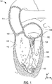
図1を最初に参照して、心臓の解剖学的構造、特に心臓の左側が記載されている。心臓104の左側は、左心房108および左心室112を含む。大動脈114は、大動脈弁120を通じて左心室112から血液を受け、この大動脈弁120は、血液が左心室112へと逆流することを防止するために働く。僧帽弁116は、左心房108と左心室112との間に位置し、そして左心房108と左心室112との間の血流を効果的に制御する。
Referring initially to FIG. 1, the anatomy of the heart, particularly the left side of the heart, is described. The left side of the
僧帽弁116(これは、図2aに関して、以下でより詳細に記載される)は、僧帽弁116の小尖が見境なく開くことを防止する「張力部材」として働く腱索124に連結される、前尖(anterior leaflet)および後尖(posterior leaflet)を含む。左心室112が収縮する場合、腱索124は、前尖を、その動きが腱索124によって制限されるまで、上方に向けて開かせる。通常、開口部の上方の制限は、前尖と後尖との接触部および逆流の防止に対応する。腱索124は、肉柱128から、より具体的には肉柱128の乳頭筋から生じる。
The mitral valve 116 (which will be described in more detail below with respect to FIG. 2a) is coupled to a
左心室112は、左心室112の壁134に付随した結合組織の繊維性の索である小柱132を含む。小柱132はまた、心臓104の右心室(示さず)から左心室112を隔てる心室中隔136に付随する。小柱132は、一般に、左心室112中の肉柱128の下に位置する。
The
図2aは、僧帽弁116および大動脈弁120の切り取り上部透視図である。大動脈弁120は、繊維性物質の骨格208aによって取り囲まれる弁壁204を有する。骨格208aは、一般に、大動脈弁120の周りの環を効果的に形成する繊維性構造とみなされ得る。骨格208aと実質的に同じ型構造である繊維性環208bは、僧帽弁116の周りに広がる。僧帽弁116は、上記のように、前尖212および後尖216を備える。前尖212および後尖216は、一般に、薄く柔軟な膜である。僧帽弁116が閉じている場合(図2aに示されるように)、前尖212および後尖216は、一般に、互いに整列して接触し、密封を形成する。あるいは、僧帽弁116が開いている場合、血液は、前尖212と後尖216との間に形成された開口部を通って流れ得る。
FIG. 2 a is a cutaway top perspective view of the
僧帽弁116に関する多くの問題が生じ得、これらの機能不全は、多くの型の病気を引き起こし得る。このような問題としては、僧帽弁逆流が挙げられるが、これに限定されない。僧帽弁逆流または僧帽弁漏出は、僧帽弁116の不完全な閉鎖に起因する左心室112から左心室108への血液の逆流である。すなわち、漏出は、間隙が前尖212と後尖216との間に形成される場合にしばしば生じる。
Many problems with the
一般に、比較的有意な間隙が、種々の異なる理由のために、(図2bに示されるように)前尖212と後尖216との間に存在し得る。例えば、間隙は、先天奇形に起因して、虚血疾患に起因して、または心臓が以前の心臓発作によって損傷を受けているために、存在し得る。間隙はまた、先天的心不全(例えば、心筋症)またはいくつかの他の型の苦痛が、心臓の拡張を引き起こす場合にも生じ得る。心臓が拡張される場合、心臓壁(例えば、左心室の壁134)は、伸びるかまたは拡張して、後尖216の伸びを引き起こし得る。前尖212は、一般に伸びないことが理解されるべきである。図2bに示されるように、前尖212と伸びた後尖216’との間の間隙220は、壁134’が伸びた場合に作成される。従って、間隙220の存在に起因して、僧帽弁116は、適切に閉じることができず、漏れ始め得る。
In general, a relatively significant gap may exist between the
僧帽弁116を通る漏出は、一般に、心臓をあまり効果的に作動させなくするので、心臓は、心臓を通る血流の適切な量を維持するためにより激しく働かなければならない。僧帽弁116を通る漏出、または一般な僧帽弁機能不全は、しばしば、CHFへの前駆状態とみなされる。一般に、心不全に関連する異なるレベルの症状が存在する。このようなレベルは、New York Heart Association(NYHA)の基本的分類システムによって分類されている。このレベルは、クラス1レベル(これは、身体的制限を実質的に有さない無症状の患者に関するレベルである)からクラス4レベル(これは、いずれの身体活動をも不快感なく行うことができず、そして安静時にさえ心不全の症状を有する患者に関するレベルである)までの範囲である。一般に、僧帽弁漏出についての矯正は、患者のNYHA分類の等級を低下させることを可能にすることにおいて成功し得る。例えば、クラス4分類を有する患者は、その分類をクラス3へと低下させ得、従って、安静時に比較的快適であり得る。
Because leakage through the
僧帽弁漏出またはより具体的にはCHFについて矯正するために使用される処置は、代表的には高度に侵襲性の開放心臓手術手順である。心室補助デバイス(例えば、人工心臓)は、心臓に欠陥がある患者に移植され得る。心室補助デバイスの移植は、しばしば費用がかかり、そして心室補助デバイスを有する患者は、延長された抗凝固治療を受けなければならない。当業者に理解されるように、抗凝固治療は、例えば、心室補助デバイス内に、血餅が形成される危険性を低減する。心室補助デバイスに伴う血栓の危険性を減少させることは所望であるが、抗凝固治療は、患者における望まれない制御不能な出血(例えば、落下の結果としての)の危険性を増大させ得る。 The procedure used to correct for mitral valve leakage or more specifically CHF is typically a highly invasive open heart surgical procedure. A ventricular assist device (eg, an artificial heart) can be implanted in a patient with a defective heart. Implantation of ventricular assist devices is often expensive and patients with ventricular assist devices must receive extended anticoagulant therapy. As will be appreciated by those skilled in the art, anticoagulant therapy reduces the risk of clots forming, for example, in ventricular assist devices. While it is desirable to reduce the risk of blood clots associated with ventricular assist devices, anticoagulant therapy can increase the risk of unwanted uncontrollable bleeding (eg, as a result of a fall) in the patient.
心室補助デバイスを移植するのではなく、ペースメーカーに類似する二心室ペーシングデバイスが、いくつかの場合(例えば、特定の非同調様式で心臓が非効果的に拍動する場合)に移植され得る。二心室ペーシングデバイスの移植は、有効であり得るが、全ての心臓患者が二心室ペーシングデバイスを受容するのに適切であるわけではない。さらに、二心室ペーシングデバイスの移植は、高価である。 Rather than implanting a ventricular assist device, a biventricular pacing device similar to a pacemaker can be implanted in some cases (eg, when the heart beats ineffectively in a particular asynchronous manner). Although implantation of a biventricular pacing device can be effective, not all heart patients are suitable for receiving a biventricular pacing device. Furthermore, implantation of biventricular pacing devices is expensive.
僧帽弁漏出を矯正するために意図される開放心臓手術手順は、特に、置換弁の移植を含む。動物(例えば、ブタ)由来の弁は、ヒトにおいて僧帽弁116を置換するために使用され得る。ブタの弁の使用は、比較的首尾よく僧帽弁を置換し得るが、このような弁は、一般に消耗し、それによって後日にさらなる開放手術を必要とする。あまり消耗しなさそうな機械弁もまた、漏出性僧帽弁を置換するために使用され得る。しかし、機械弁が移植される場合、血栓塞栓症の危険性が増大し、そして患者は一般に、延長した抗凝固治療を受ける必要がある。
Open heart surgical procedures intended to correct mitral valve leakage include, in particular, replacement valve implantation. Valves from animals (eg, pigs) can be used to replace
侵襲性の少ない手術手順は、ポートアクセス手順に関連する心臓バイパス手術を含む。ポートアクセス手順について、心臓は、患者の胸全体を開胸することとは対照的に、少数の肋骨を切断することによってアクセスされ得る。言い換えれば、患者の胸骨を開口するのではなくて、少数の肋骨が、ポートアクセス手順で切断され得る。 Less invasive surgical procedures include cardiac bypass procedures associated with port access procedures. For port access procedures, the heart can be accessed by cutting a few ribs as opposed to opening the entire patient's chest. In other words, rather than opening the patient's sternum, a few ribs can be cut with a port access procedure.
僧帽弁漏出、さらに僧帽弁逆流の矯正において特に成功している1つの開放心臓手術手順は、輪状形成手順である。輪状形成手順の間に、弁形成リングを僧帽弁に移植して、伸びた僧帽弁116のサイズが相対的に正常なサイズまで減少されるようにし得る。図3は、弁形成リングの略図である。弁形成リング304は、ほぼ正常な僧帽弁の外形のように成形される。すなわち、弁形成リング304は、実質的に文字「D」のように成形される。代表的には、弁形成リング304は、生体適合材料(例えば、プラスチック)(これは、DACRONメッシュ被膜(mesh covering)を有する)のロッドまたはチューブから形成され得る。
One open heart surgical procedure that has been particularly successful in correcting mitral valve leakage and also mitral regurgitation is the annuloplasty procedure. During the annuloplasty procedure, an annuloplasty ring may be implanted into the mitral valve so that the size of the elongated
弁成形リング304を移植するために、外科医は、僧帽弁の心房側上の僧帽弁に、弁成形リング304を外科的に装着する。リング304を導入するための従来の方法は、患者の胸骨を開口して、患者に心臓バイパス機を設置することを伴う開放心臓手術を必要とする。図4中に示されるように、弁成形304は、僧帽弁316の頂上部分の後尖318および前尖320に縫合される。僧帽弁316上に弁成形リング304を縫合する際に、外科医は、一般的に、針およびネジを使用して僧帽弁組織から比較的大量の組織(例えば、組織の1/8インチのバイト)を、続いて、弁成形リング304からより小さいバイトを交互に獲得する。一旦ネジが弁成形リング304と僧帽弁組織とを緩く連結させると、弁成形リング304は、僧帽弁316上に滑り、その結果、以前に(うっ積した心臓に起因して)伸びた組織は、例えば、弁成形リング304、および弁成形リング304を僧帽弁組織に結合させるネジにより加えられる張力を使用して、効率的に引っ張られる。結果として、前尖320と後尖318との間のギャップ(例えば、図2bのギャップ220)は、実質的に閉鎖され得る。僧帽弁がリング304によって成形される後、前尖320および後尖318は、新しい接触線(contact line)を作製するように再形成して、そして、僧帽弁318が正常な僧帽弁のように見え、そして、そのように機能することを可能にする。
To implant the
一旦移植されると、組織は、一般に、弁成形リング304を超えて増殖して、弁成形リング304と僧帽弁316との間の接触線は、本質的に、僧帽弁316が正常な僧帽弁のように見え、そしてそのように機能することを可能にする。弁成形リング304を受容する患者は、抗凝固性治療に供され得るが、患者はおよそ数週間(例えば、組織が、弁成形リング304にわたり増殖するまで)、治療に供されるのみであるので、治療は、大規模ではない。
Once implanted, the tissue generally grows beyond the
僧帽弁漏出を減少させる際に一般的に有効である第2の手術手順は、僧帽弁中の単一の縁から縁への(edge−to−edge)縫合を配置することを伴う。図5を参照にして、このような手術手順(例えば、Alfieriステッチ手順またはボウタイ(bow−tie)修復手順)が記載される。縁から縁へのステッチ404は、僧帽弁416の前尖420と後尖418との間で規定されたギャップ408のほぼ中心で領域を一緒にステッチするために使用される。一旦ステッチ404が所定の位置でなされると、ステッチ404は、示されるように、後尖418に対して前尖420を保持する縫合を形成するために引っ張られる。ギャップ408のサイズを減少させることで、僧帽弁416を通った漏出の量は、実質的に減少され得る。
A second surgical procedure that is generally effective in reducing mitral valve leakage involves the placement of a single edge-to-edge suture in the mitral valve. With reference to FIG. 5, such a surgical procedure (eg, an Alfieri stitch procedure or a bow-tie repair procedure) is described. Edge-to-
縁から縁へのステッチ404の配置は、一般的に、ギャップ408を通った僧帽弁漏出の量を減少させることに成功するが、縁から縁へのステッチ404は、慣習的に、開放心臓手術を介してなされる。さらに、縁から縁へのステッチ404の使用は、一般的に、うっ積して拡張した心臓を有する患者に適切でない。なぜならば、血圧が心臓を外向きに拡張させて、縁から縁へのステッチ404対して比較的多量のストレスを及ぼし得るからである。例えば、約120/80またはそれより高い血圧は、代表的に、縁から縁へのステッチ404が、破壊したかまたは僧帽弁組織を裂く程度まで心臓を外側に拡張させるのに、十分である。
While the edge-to-
侵襲性手術手順が、僧帽弁漏出の処置に効果的であることが証明されている一方で、侵襲性手術手順は、しばしば、重要な欠点を有する。患者が開放心臓手術を受けるときはいつでも、感染の危険がある。胸骨を切断して、心肺バイパス機を使用することはまた、短期神経欠損および長期神経欠損の両方の顕著な発生を生じることが示されている。さらに、開放心臓手術の複雑さおよび付随する大幅な回復時間を考えると、CHF症候群によって極度に不自由ではない人々(例えば、クラス1分類の人々)は、矯正手術を受けないように選択され得る。さらに、開放心臓手術が最も必要な人々(例えば、クラス4分類の人々)は、痩せすぎか、または衰弱しすぎてのいずれかで手術を受けられ得ない。従って、手術的に修復されている僧帽弁により改善され得る多くの人々は、手術を受けられ得ない。
While invasive surgical procedures have proven effective in the treatment of mitral valve leakage, invasive surgical procedures often have significant drawbacks. Whenever a patient undergoes open heart surgery, there is a risk of infection. Cutting the sternum and using a cardiopulmonary bypass machine has also been shown to produce significant occurrences of both short-term and long-term neurological deficits. Furthermore, given the complexity of open heart surgery and the associated significant recovery time, people who are not extremely crippled by CHF syndrome (eg, those in the
従って、必要とされることは、僧帽弁漏出のための最小限の侵襲性処置である。詳細には、所望されることは、従来の手術侵襲を必要としない、僧帽弁の前尖と後尖との間の漏出を減少する方法である。 Therefore, what is needed is a minimally invasive procedure for mitral valve leakage. In particular, what is desired is a method for reducing leakage between the anterior and posterior mitral valves of the mitral valve that does not require conventional surgical invasion.
(発明の要旨)
本発明は、輪状形成を実施する非侵襲性の方法に関する。本発明の1つの局面に従って、心臓の僧帽弁において手順を実施するための方法は、左心室に移植物を挿入する工程、および実質的に僧帽弁の下の左心室に移植物を配向させる工程を包含する。この移植物は僧帽弁付近の組織に装着し得る。1つの実施形態において、移植物は、僧帽弁に対応する弧の長さを実質的に短くするために短縮される。別の実施形態において、移植物は大動脈および大動脈弁を通って左心室に挿入される。
(Summary of the Invention)
The present invention relates to a non-invasive method for performing annuloplasty. In accordance with one aspect of the present invention, a method for performing a procedure on a mitral valve of a heart includes inserting an implant into the left ventricle and orienting the implant into the left ventricle substantially below the mitral valve. Including the step of The implant can be attached to tissue near the mitral valve. In one embodiment, the implant is shortened to substantially shorten the length of the arc corresponding to the mitral valve. In another embodiment, the implant is inserted through the aorta and the aortic valve into the left ventricle.
なお別の実施形態において、移植物と組織とを接続させる工程は、トラックとしてガイド要素を用いて左心室へカテーテルを導入する工程を包含する。カテーテルは、少なくとも1つの、結合要素を備える鋭利なワイヤを備え、そして端部を有する。この端部は、移植物を組織に実質的に結合させるために、移植物および組織を介して実質的に押され得る。このような実施形態において、結合要素はT字型バーであり得る。 In yet another embodiment, connecting the implant to the tissue includes introducing a catheter into the left ventricle using a guide element as a track. The catheter comprises at least one sharp wire with a coupling element and has an end. This end can be substantially pushed through the implant and tissue to substantially bond the implant to the tissue. In such embodiments, the coupling element can be a T-shaped bar.
カテーテルを用いて心臓の左心室にアクセスすることにより、僧帽弁上で輪状形成を実施することは、僧帽弁漏出を処置する場合に複雑な手術手順を回避するのを可能にする。手術手順を回避することによって、一般的に輪状形成からの恩恵を受け得る患者は、輪状形成をより利用しやすくなる。僧帽弁漏出は、しばしばうっ血性心不全の初期徴候と見なされるので、漏出問題を矯正する非侵襲性の輪状形成手順は、侵襲性の輪状形成手順に適し得ない多くの患者の生活の質を非常に改善し得る。 Performing annuloplasty on the mitral valve by accessing the left ventricle of the heart using a catheter allows for avoiding complex surgical procedures when treating mitral valve leakage. By avoiding surgical procedures, patients who can generally benefit from annuloplasty become more accessible to annuloplasty. Because mitral valve leakage is often seen as an early sign of congestive heart failure, a non-invasive annuloplasty procedure that corrects the leakage problem can reduce the quality of life for many patients who cannot be adapted to an invasive annuloplasty procedure. Can be greatly improved.
本発明の別の局面に従って、心臓の左心室にアクセスする方法は、大動脈内に細長本体を導入する工程、および細長本体の少なくとも一部分を、大動脈弁を通過させる工程を包含する。一旦、この部分が大動脈弁を通過すると、この部分は左心室に配置されるか、または位置付けされる。1つの実施形態において、この部分を左心室に配置させる工程は、僧帽弁に関連する面と、左心室の乳頭筋に関連する面との間の間隙にこの部分を位置させる工程を包含する。このような実施形態において、細長本体は移植物であり得、そして左心室にこの部分を配置させる工程は、僧帽弁付近の組織に対して実質的に移植物を位置決めする工程をさらに包含し得る。 In accordance with another aspect of the present invention, a method for accessing the left ventricle of the heart includes introducing an elongate body into the aorta and passing at least a portion of the elongate body through the aortic valve. Once this part has passed the aortic valve, this part is placed or positioned in the left ventricle. In one embodiment, placing the portion in the left ventricle includes positioning the portion in a gap between a surface associated with the mitral valve and a surface associated with the left ventricular papillary muscle. . In such embodiments, the elongate body can be an implant, and placing the portion in the left ventricle further comprises positioning the implant relative to tissue near the mitral valve. obtain.
本発明のなお別の局面に従って、輪状形成を実施するための方法は、左心室に伸長可能なアレンジメントのような移植物を提供するために、左心室にアクセスする工程を包含する。一旦、左心室がアクセスされると、伸長可能なアレンジは、心臓の僧帽弁周囲の線維組織に接合される。伸長可能なアレンジメントは、僧帽弁の心室側に接合される。最終的に、伸長可能アレンジメントは、僧帽弁に対応する弧の長さを実質的に短くするように短縮される。1つの実施形態において、伸長可能なアレンジメントは移植物であり、そして伸長可能なアレンジメントを伸長することは、実質的に移植物をつぶすことを含む。 In accordance with yet another aspect of the invention, a method for performing annuloplasty includes accessing the left ventricle to provide an implant, such as an arrangement that is extensible to the left ventricle. Once the left ventricle is accessed, the expandable arrangement is joined to the fibrous tissue surrounding the mitral valve of the heart. The extensible arrangement is joined to the ventricular side of the mitral valve. Finally, the expandable arrangement is shortened to substantially shorten the length of the arc corresponding to the mitral valve. In one embodiment, the extensible arrangement is an implant and extending the extensible arrangement includes substantially collapsing the implant.
本発明のなお別の実施形態に従って、輪状形成手順において使用されるのに適するデバイスは、メッシュの構造体および伸長要素を備える。この構造はばね様要素であり、これは、伸長が適用される場合、それ自体に圧縮されるように構成される。このメッシュは構造体上に配置される織ったメッシュ(woven mesh)であり、伸長要素は構造体に伸長を適用するように配置される。このデバイスは、心臓の僧帽弁の近位の線維組織に係合される場合、伸長要素が、このデバイスに、僧帽弁に対応する弧の長さを短くさせるようなものである。1つの実施形態において、デバイスは僧帽弁の心室側に係合されるのに適している。別の実施形態において、デバイスは、構造体を通って伸長するカプラおよび線維状組織にデバイスを係合させるためメッシュを備える。このような実施形態において、カプラはT字型バーの形態をとり得る。 In accordance with yet another embodiment of the present invention, a device suitable for use in an annuloplasty procedure comprises a mesh structure and an elongated element. This structure is a spring-like element, which is configured to compress itself when stretch is applied. The mesh is a woven mesh placed on the structure, and the stretch elements are placed to apply stretch to the structure. The device is such that when engaged with the fibrous tissue proximal to the mitral valve of the heart, the elongate element causes the device to shorten the length of the arc corresponding to the mitral valve. In one embodiment, the device is suitable for being engaged on the ventricular side of the mitral valve. In another embodiment, the device comprises a coupler for extending through the structure and a mesh for engaging the device with fibrous tissue. In such an embodiment, the coupler may take the form of a T-shaped bar.
本発明のなお別の局面に従って、輪状形成手順において使用されるためのデバイスは、圧縮可能部材および短縮デバイスを備える。圧縮可能部材は、カテーテルを通る左心室への挿入ための開口非圧縮位置と閉鎖位置との間を移動可能である。短縮デバイスは、開口非圧縮位置と閉鎖位置との間に圧縮部材を移動するように作動可能である。一般的に、デバイスは、僧帽弁の開口を減少させるように位置決めされる。1つの実施形態において、デバイスはまた、圧縮部材の少なくとも一部分にわたって伸長するメッシュカバーを備える。 In accordance with yet another aspect of the invention, a device for use in an annuloplasty procedure comprises a compressible member and a shortening device. The compressible member is movable between an open uncompressed position for insertion into the left ventricle through the catheter and a closed position. The shortening device is operable to move the compression member between an open uncompressed position and a closed position. Generally, the device is positioned to reduce mitral valve opening. In one embodiment, the device also comprises a mesh cover that extends over at least a portion of the compression member.
本発明のこれらの利点および他の利点は、以下の詳細な説明を読解して、図面の様々な図を研究することで理解される。 These and other advantages of the present invention will be understood by reading the following detailed description and studying the various figures of the drawings.
(実施形態の詳細な説明)
侵襲性の開心術(心臓切開手術)の手順は、一般的に僧帽弁での漏出(leakage)の処置において効果的である。しかし、開心術手順は、ある患者(例えば、非常に不健康であるとみなされる虚弱な患者)によっては特に有害となり得、そして他の患者(例えば、無症候性の患者および手術手順の実施を望まない患者)にとっては所望され得ない。従って、僧帽弁の漏出またはより一般的な僧帽弁不全を矯正するための開心術手順は、僧帽弁漏出を減少させるか、または排除することよって改善される可能性のある多くの患者にとって適切ではない。
(Detailed description of embodiment)
Invasive open-heart surgery (cardiotomy) procedures are generally effective in the treatment of mitral valve leakage. However, open-heart surgery procedures can be particularly harmful for some patients (eg, frail patients who are considered very unhealthy), and others (eg, asymptomatic patients and wishing to perform surgical procedures) Not desired). Therefore, open-heart surgery procedures to correct mitral valve leakage or more common mitral valve insufficiency may be improved by reducing or eliminating mitral valve leakage Not appropriate for.
カテーテルベースの輪状形成手順は、患者が開心術を受けることも、心肺バイパスを配置されることも必要とせずに、患者において輪状形成(環状形成)を実施し得る。カテーテルは、ガイドワイヤおよび移植物を僧帽弁の心室側(すなわち、僧帽弁の下)に位置付けるために、大動脈を通って心臓の左心室内に導入され得る。またカテーテルを用いて、移植物を、僧帽弁周囲の心臓の骨格と結合している線維組織に連結し得、そして、この衣食物に緊張を与えることによって僧帽弁の前尖と僧帽弁の後尖との間の漏出を低減し得る。 A catheter-based annuloplasty procedure can perform annuloplasty (annular formation) in a patient without requiring the patient to undergo open heart surgery or to have a cardiopulmonary bypass. A catheter can be introduced through the aorta and into the left ventricle of the heart to position the guidewire and implant on the ventricular side of the mitral valve (ie, below the mitral valve). A catheter can also be used to connect the implant to the fibrous tissue associated with the heart skeleton around the mitral valve, and by tensioning the garment food, the anterior mitral valve and the mitral valve Leakage between the valve leaflets can be reduced.
輪状形成手順を実行するためにカテーテルを使用することによって、開心術およびバイパス手順を用いずに輪状形成手順が可能となる。輪状形成に付随する回復時間、および輪状形成に付随する危険は、実質的に最小化され得る。結果として、輪状形成はより利用しやすい手順となる。なぜなら、僧帽弁漏出に対する処置を今までに受けていない多くの患者(例えば、虚弱な患者および無症候性の患者)は、カテーテルベースの輪状形成の実施を選択し得るからである。 By using a catheter to perform the annuloplasty procedure, the annuloplasty procedure is possible without using open heart surgery and bypass procedures. The recovery time associated with annulus formation and the risk associated with annulus formation can be substantially minimized. As a result, ring formation is a more accessible procedure. This is because many patients (e.g., weak and asymptomatic patients) who have not previously been treated for mitral valve leakage may choose to perform a catheter-based annuloplasty.
カテーテルベースの輪状形成手順を始めるために、送達管およびJ字型カテーテルは、大動脈を通って心臓の左心室内に挿入され得る。大動脈を通る送達管およびJ字型カテーテルの挿入は、心臓の左心室が柵状織または腱索(cordae tendonae)と接触することなく、左心室内に実質的に到達されることを可能にする。図6aは、本発明の実施形態に従う図式的な送達管およびJ字型カテーテルの概略図である。送達管604は実質的に環状の断面を有し、そしてJ字型カテーテル608を受け取るように構成される。必要ならば、J字型カテーテル608は、送達管604を通って長軸方向に移動させるためにアレンジされ、送達管604において開口される。
To begin the catheter-based annuloplasty procedure, the delivery tube and J-shaped catheter can be inserted through the aorta and into the left ventricle of the heart. Insertion of a delivery tube and J-shaped catheter through the aorta allows the left ventricle of the heart to be substantially reached into the left ventricle without contact with the palisade or chordae tendonae . FIG. 6a is a schematic illustration of a schematic delivery tube and J-shaped catheter according to an embodiment of the present invention.
一般的に、送達管604は細長の本体であり、これは、可撓性で、耐久性で、生体適合性の材料、例えば、ナイロン、ウレタンまたはナイロンとウレタンのブレンド(例えば、PEBAX(登録商標))から形成され得る。同様に、J字型カテーテル608(これもまた、細長本体である)はまた、生体適合性材料から形成され得る。J字型カテーテル608を形成するために使用される材料もまた、代表的に、比較的可撓性である。記載される実施形態において、J字型カテーテル608の上部は、J字型カテーテル608の先端部が比較的湾曲した形状(例えば、「J」字型)を維持するのを可能にするために十分剛体である。図7a〜7cについて以下に記載されるように、J字型カテーテル608の湾曲は、ガターカテーテルの位置決めを容易にするように構成される。
In general,
図6bは、本発明の実施形態に従って心臓内で位置決めされた、送達管604およびJ字型カテーテル608の概略図である。示されるように、送達管604およびJ字型カテーテル608が大腿動脈を通って効果的に「蛇行」または挿入された後に、送達管604およびJ字型カテーテル608の位置は、心臓616の大動脈620内で位置決めされる。J字型カテーテル608の先端626(これは、J字型カテーテル608の本体から実質的に直角に配向している)および送達管604の端部は、これらが大動脈弁630を通過するように配向される。従って、送達管604の端部および先端626は、左心室624の頂部に位置決めされ、この位置では、左心室624の壁632は比較的平滑である。左心室624の頂部が比較的平滑であることにより、カテーテルは、壁632に沿ってカテーテルの先端を案内することによって、左心室624内で適切に位置決めされることが可能になる。1つの実施形態において、先端626は、僧帽弁628の心室側で、僧帽弁628のおよそすぐ下に位置決めされるように、配向される。
FIG. 6b is a schematic illustration of a
一旦、左心室624内で位置決めされると、J字型カテーテル608は、送達管604内で回転され得、その結果、先端626は、そこを通して供給されるガターカテーテルが壁632の輪郭に沿うことを可能にし得る。代表的に、ガターカテーテルは、乳頭筋640に関する平面、僧帽弁628の後尖に関する平面、腱索642、および壁632の間に効果的に規定される領域で、壁632の輪郭に沿って延びる。「溝」は、このような領域(area)または領域(region)に位置し、そしてより具体的には、比較的わずかな量の小柱が存在する、僧帽弁628の実質的に右下に位置する。
Once positioned within the
図7a〜7cを参照して、ガターカテーテルが、本発明の実施形態に従って記載される。ガターカテーテル704(これは、図7aに示されるように、カテーテルアセンブリ702の一部である)は、J字型カテーテル626を通って延びるように配置され、その結果、ガターカテーテル704は、僧帽弁のすぐ下の左心室内に進められ得る。バルーン先端(図示せず)を備え得るガターカテーテル704は、代表的に、ナイロン、ウレタン、またはPEBAX(登録商標)のような、可撓性の材料から形成される。1つの実施形態において、操縦可能であるガターカテーテル704は、形状記憶金属を使用して形成され得る。
With reference to FIGS. 7a-7c, a gutter catheter is described in accordance with an embodiment of the present invention. The gutter catheter 704 (which is part of the
図7aおよび図7b(これらは、位置710においてとったカテーテルアセンブリ702の断面を表す)に示されるように、ガターカテーテル704は、少なくとも部分的に、J字型カテーテル608の内部に位置決めされ、このJ字型カテーテルは、次に、送達管604内に少なくとも部分的に位置決めされる。ガターカテーテル704は、J字型カテーテル608の内部で自由に回転し得、そしてJ字型カテーテル608を通って延び得、一方でJ字型カテーテル608は、送達管604の内部で自由に回転し得、そして送達管604を通って延び得る。
As shown in FIGS. 7a and 7b (which represent a cross-section of the
次に、図7cを参照して、心臓の左心室内でのガターカテーテル704の位置決めが、本発明の実施形態に従って記載される。説明を簡単にし、そして議論を簡単にするために、左心室720内でのガターカテーテル704の表現は、同一縮尺では描かれていないことが、理解されるべきである。例えば、左心室720の壁724と僧帽弁728との間の距離は、誇張されている。さらに、大動脈弁732内での送達管604の位置決め、従って、J字型カテーテル608およびガターカテーテル704の位置決めが変動し得ることもまた、理解されるべきである。
Referring now to FIG. 7c, the positioning of the
ガターカテーテル704は、J字型カテーテル608の先端626を通って突出し、そして操縦によって、僧帽弁728のすぐ下の左心室720の壁724の輪郭に沿って(すなわち、左心室720の溝に沿って)、僧帽弁728の弧の形状と類似の弧の形状を、実質的に形成する。左心室720の壁724は、僧帽弁728のすぐ下において、比較的平滑である(すなわち、一般的に小柱を含まない)。従って、大動脈弁732を通して左心室720の上部にカテーテルアセンブリ702を挿入することによって、ガターカテーテル704は、実質的に小柱または腱索によって閉塞されることなく、壁724に沿って僧帽弁720内で誘導されることが可能になる。
The
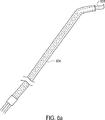
ガターカテーテル704は、一般に、開口部または管腔(図示せず)を備え、これは、ガイドワイヤを収容するような大きさにされ、ここを通してガイドワイヤが挿入され得る。この開口部は、ガターカテーテル704の中心軸(すなわち、図7aに示されるような中心軸730)に沿って位置し得る。ガターカテーテル704を通してガイドワイヤを送達することによって、ガイドワイヤが壁724の輪郭に効果的に従うことが可能となる。一般に、ガイドワイヤは、係留先端を備え得、これは、ガイドワイヤが壁724に実質的に係留されることを可能にする。図8は、ガイドワイヤが本発明の実施形態に従って位置決めされた、心臓の左側の図式的な切取り上面図である。議論を簡単にするために、図8における心臓の左側の表現は、同一縮尺では描かれていないこと、および種々の特徴が誇張されていることが、理解されるべきである。ガイドワイヤ802は、左心室720の壁724に沿って位置決めされる。一旦、ガイドワイヤ802が図7a〜7cのガターカテーテル704を通して挿入され、そして係留先端806を使用して壁724に係留されると、ガターカテーテル704は、J字型カテーテル708と共に、患者の身体から引き抜かれる。ガイドワイヤ802が壁724に係留された後は、送達管604は、代表的に、大動脈内で位置決めされたままであることが、理解されるべきである。
The
ガイドワイヤ802(これは、ステンレス鋼または形状記憶材料のような材料から形成され得る)は、一般に、ガイドワイヤ802が壁724の大部分に沿って効果的に通過するように、係留される。代表的に、ガイドワイヤ802は、軌道として働き、これを覆って、移植物が位置決めされ得る。図9aを参照すると、移植物の1つの実施形態は、本発明に従って説明されている。移植物のセクション904は、開口部908をその中に備え、これはガイドワイヤ(すなわち、図8のガイドワイヤ802)を覆って調和するように配置される。一般的に、移植物は、大腿動脈、大動脈、および大動脈弁を介して挿入されるようにサイズ決めされている。セクション904は、生体適合性構造912を備え、これを覆って、生体適合性の織られたメッシュ(網目状組織)916が配置されている。この移植物が僧帽弁の下に位置付けられると、メッシュ916は、僧帽弁組織の再成長がメッシュ916の中およびその周囲で起こることを可能にする。構造912が様々な異なる形態を取ると、1つの実施形態において、構造は解放したバネ要素として形成され得、これは例えば、緊張が図11aおよび図11bに関して以下で描かれるように移植物全体に対して適用されたときに、それ自体に対して効果的に短くな得るか、または、折りたたまれ得る。
A guide wire 802 (which can be formed from a material such as stainless steel or shape memory material) is generally anchored so that the
図9bは、本発明の実施形態に適合するガイド心臓の左側面の切り取り上面図であり、ここで、移植物は、本発明の実施形態に従うガイドワイヤを覆って挿入されている。図9bに示した心臓の一部分の相対的な寸法は、同一縮尺ではなく、そしていくつの寸法は、議論の目的のために誇張されていることが理解されるべきである。移植物924は、ガイドワイヤ802を覆って位置付けられ、その結果、移植物924は、僧帽弁728の湾曲した外形に実質的に従い、故に、僧帽弁728の周囲の繊維状組織970に従う。すなわち、移植物924は、おおよそ馬蹄に類維した形状をしている。ガイドワイヤ802は、移植物924を効果的に支持し、左心室720中で僧帽弁728の実質的な下に移植物924を位置付ける。
FIG. 9b is a cutaway top view of the left side of a guide heart that is compatible with embodiments of the present invention, where the implant has been inserted over a guidewire according to an embodiment of the present invention. It should be understood that the relative dimensions of the portions of the heart shown in FIG. 9b are not to scale and some dimensions are exaggerated for discussion purposes. The
図5に関して上で議論されるように、移植物924は、僧帽弁728の底面に対して移植物924を効果的に押すように膨張し得るバルーンに結合し得る。図9cを参照すると、僧帽弁728の底面に対する移植物924の位置付けは、本発明の実施形態に適合して説明されている。図9cは、心臓の左側の概略的な側方断面図である。一旦、移植物924がガイドワイヤ802を覆って位置付けられると、バルーン960(これは、一般に移植物924に結合している)は、膨張し得る。一旦、膨張すると、バルーン960は、左心室720中の僧帽弁728と乳頭筋964との間を実質的に満たす。バルーン960を膨張させることによって、バルーン960内の圧力が、僧帽弁728周囲の線維輪の繊維組織970を移植物924に効果的に押し付けることを可能にする。1つの実施形態において、バルーン960は、エラストマー性材料から形成される。
As discussed above with respect to FIG. 5, the
一旦、移植物924が適切に位置付けられると、T字型バー送達カテーテルは、図5に関して上で言及されているように、移植物924を介して挿入され得る。T字型バー送達カテーテルは、移植物924を、僧帽弁728の周囲の線維輪と結合してる線維組織970に結合するのに適切なT字型バーを提供するものとして説明されるが、他の方法が移植物924を組織に結合し得るように使用されることが理解されるべきである。組織を高い信頼性で保持し得る、実質的に任意の機構またはが使用され得る。適切なデバイスとしては、アンビルアレンジメント、ステープル、クリップ、バルブ、および縫糸が挙げられるがこれらの限定されない。
Once the
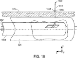
次に、図10を参照すると、T字型バー送達カテーテルの1つの実施形態は、本発明の実施形態に適合するように説明さている。T字型バー送達カテーテル1004は、ガイドワイヤ802を覆うように、かつ移植物924の中で、位置付けられ得る。T字型送達カテーテル1004および移植物924は、同一縮尺で描かれていないことに留意されたい。送達カテーテル1004中に、T字型バー1012を保持するワイヤ1008がある。T字型バー1012は、T字型バー1012(例えば、僧帽弁周囲の線維組織970に対して移植物924を保持するT字型バー1012)を効果的に締め付けるのに使用できる延長部1016に結合する。代表的には、ワイヤ1008の尖端部または鋭端部1020は、移植物924および線維組織970の両方を貫通する。一旦、末端1020およびT字型バー1012が両方とも線維組織970上方に位置付けられると、T字型バー1012が、線維組織970の上方、すなわち、線維組織970の房側上に留まる一方で、ワイヤ1008を引っ込めることができる。収縮ワイヤ1008および、1つの実施形態において、完全に患者の外にある送達カテーテル1004は、さらなるT字型バーがワイヤ1008上に装填されることを可能にする。一旦、さらなるT字型バーが、ワイヤ1008に位置付けられ得ると、ワイヤ1008は再び送達カテーテルに1004に再挿入され得、そして送達カテーテル1004は、移植物924に沿った別の位置で線維組織970にT字型バーが本質的に付着することを可能にするために使用され得る。
Referring now to FIG. 10, one embodiment of a T-bar delivery catheter is described to be compatible with embodiments of the present invention. T-
一般的に、移植片924と繊維組織970との間の連結を生成するのに使用され得るT字型バー1012の数は、広範に変化し得る。例として、約6個または約8個のT字型バー1012の使用が適切であり得るが、それより少ないかまたはそれより多いT字型バー1012が、必要な場合に使用され得る。全てのT字型バー1012が、移植片924に対して適所に配置された後、T字型バー1012は、T字型バー1012に連結した延長部1016を引っ張り、結ぶことによって締め付けられ得る。
In general, the number of T-
T字型バー1012は、移植片924を効果的に短縮するため(すなわち、移植片924を用いて処置または治療を提供するため)に、移植片924と繊維組織970との間の比較的緊密な接触を生成している間、移植片924は代表的に、張力がかけられている。すなわち、僧帽弁728の大きさは、移植片924に張力をかけることにより減少され得る。図11aおよび11bに関して、移植片に張りを提供する1つの方法が、本発明の実施形態に従って記載される。移植片1124は、僧帽弁1128の下(すなわち、心臓の左心室)に配置され、そして移植片1124を繊維組織1170に効果的に結合する連結装置1112を用いて僧帽弁1128に対して保持される。記載される実施形態において、連結装置1112はT字型バーであるが、他の連結装置(例えば、ステープルまたはバーブ)が、T字型バーの代わりに使用され得ることが理解されるはずである。
T-shaped
後尖1132と前尖1134との間の隙間1130が明白なように伸びた僧帽弁1128の大きさを減少させるために、移植片1124内に挿入される引張り要素1140は、移植片1124の弧の長さを短縮するよう引っ張られ得る。一般的に、引張り要素1140は、移植片1134が左心室に挿入された後に、ガテーテルを用いて移植片1134内に挿入され得る。あるいは、引張り要素1140は、移植片1134に予め装着され得る。示されるように、引張り要素1140は、紐であり、僧帽弁1128の湾曲した外部縁に関する弧の長さを効果的に減少させるために引き寄せられ、そして最終的に結ばれ得る。引張り要素1140の引き寄せおよび結びは、移植片1134内に挿入されたカテーテル1150の使用を通して達成され得る。
In order to reduce the size of the
引張り要素1140が引張られる場合、移植片1124は、それ自身上で効果的に崩壊するか、または短縮される。上記のように、移植片1124は、メッシュで覆われたばね様構造から形成され得る。ばね様構造は、張力が適用された場合にそれ自身上で崩壊され得るかまたは短縮され得る細長本体である。従って、図11bに示されるように、僧帽弁1128に関する弧の長さは、例えば、2:1比で減少され得る。僧帽弁1128に関する弧の長さを減少することにより、隙間1130が大きく減少される。1つの実施形態において、隙間1130は、僧帽弁1128の漏れがないように効果的に消される。
When the pulling
1つの実施形態において、移植片1124は、移植片1124に関する屈曲の半径が変化し得るように、それ自身上で屈曲し、そして崩壊するよう設計されている。すなわち、移植片1124に張力を適用することによって、移植片1124の屈曲半径は減少される。移植片1124は、僧帽弁1134の近位で繊維組織1170に連結されるので、移植片1124の屈曲半径が減少される場合、僧帽弁1134の大きさも減少される。
In one embodiment, the
引張り要素1140の構成が本明細書中に示されるものと相違することが認識されるべきである。引張り要素1140は、紐または結ばれ得る類似の要素であり得るが、引張り要素1140はまた、引張りにより張力が適用され得る実質的に任意の要素であり得る。別の特定の適切な張力要素は、ケーブルラップまたは「ジップタイ(zip tie)」であり、これは、一般的に、それ自体上で輪になり、次いで、例えば、カテーテル(例えば、図11aのカテーテル1150)の使用を通して引き寄せにより締められ得る要素である。引き寄せの後にこのような要素を放出することは、一般的に、この要素に関する張力を有意に変化させない。
It should be appreciated that the configuration of the
引張り要素1140は、調節可能または崩壊可能な移植片1124と組み合わせて、移植片1124が必要とされる場合に連続的に調節されることを可能にする。例として、最初のカテーテルに基づく輪状形成後のある時点で、患者が移植片1124の再調整を必要とする場合、この患者は、移植片1124における張力を変更するよう設計された比較的簡単なカテーテルに基づく手順を受け得る。さらに、単一の大きさの移植片1124は、すでに移植されている場合、伸長した僧帽弁1128の大きさを適切に減少させるために調整され得るので、特定の移植片1124の大きさに基づき使用するために移植片1124を選択する必要性は、減少され得る。
The pulling
一旦、移植片1124が適切に調整されると、患者は、僧帽弁組織の移植片1124周囲および移植片1124中での成長が成功し始めるまで抗凝血治療に供され得る。組織の成長が所望のレベルに達した場合、次いで、新たな組織が移植片1124を効果的に支持し得、そして患者は、一般的に抗凝血治療を停止し得る。カテーテルに基づく輪状形成が切開手術ではなく、比較的非侵襲性であるとみなされているので、カテーテルに基づく輪状形成からの回復時間は、従来の外科的輪状形成手順により必要とされる回復時間と比較した場合、相対的に短い。
Once the
図12を参照して、カテーテルに基づくシステムを使用する輪状形成手順の実施が、本発明の実施形態に従って記載される。一旦、患者が準備されると(例えば、鎮静されると)、輪状形成手順504は、送達管およびJ字型カテーテルを、患者の心臓の左心室に挿入することで開始し得る。これらの送達管およびJ字型カテーテルは、大腿動脈を通して患者の身体に挿入され、そして大腿動脈および大動脈を通され、そして心臓の左心室に入り得る。一般に、J字型カテーテルは、送達管内に位置決めされる。送達管およびJ字型カテーテルの1つの実施形態は、図6aおよび6bに関して上で記載された。当業者によって理解されるように、送達管およびJ字型カテーテルは、代表的に、それぞれ、大動脈弁を通して左心室に到る。
With reference to FIG. 12, the performance of an annuloplasty procedure using a catheter-based system will be described in accordance with an embodiment of the present invention. Once the patient is prepared (eg, sedated), the
一旦、送達管およびJ字型カテーテルが左心室内で位置決めされると、工程512において、ガターカテーテルが、J字型カテーテルを通して延ばされ得る。図7a〜cに関して上で議論されたように、ガターカテーテルは、僧帽弁の実質的にすぐ下の左心室の壁の溝に対して効果的に延びるように配置される。具体的には、ガターカテーテルは、僧帽弁と乳頭筋(musculi papillareまたはpapillary muscle)との間の、左心室の空間に位置決めされ得る。ガターカテーテルは、しばしば、操縦可能な可撓性の先端を有する。1つの実施形態において、ガターカテーテルの先端は、膨張可能なバルーンに結合され得る。J字型カテーテルは、他の目的のうちでもとりわけ、ガターカテーテルが最初に、ガターカテーテルが左心室の壁に沿って位置決めされ得るような適切な方向に配向されることを可能にするように働く。
Once the delivery tube and the J-shaped catheter are positioned within the left ventricle, in
工程516において、係留装置を備えるガイドワイヤは、ガターカテーテルを通して(例えば、ガターカテーテルの管腔または開口を通して)送達され得る。ガイドワイヤは、左心室の壁に対してガターカテーテルの概略に続くように、ガターカテーテルを通して送達される。ガイドワイヤが送達された後、ガイドワイヤの係留装置は、工程520において、左心室の壁に対して係留される。左心室の壁に対してガイドワイヤを係留すること、またはそうでなければガイドワイヤを移植することにより、ガイドワイヤが、左心室内のその位置に維持されることが可能になる。
In
J字型カテーテルおよびガターカテーテルは、図8に関して上述されたように、工程524において、ガイドワイヤを左心室に係留したまま、大腿動脈を通して左心室から引き抜かれる。一旦、J字型カテーテルおよびガターカテーテルが左心室から除去されると、実質的に収縮したバルーンに連結され得る移植片が、工程528においてガイドトラックとしてガイドワイヤを用いて左心室に挿入される。言い換えると、僧帽弁に連結されることが意図される移植片は、僧帽弁の下(僧帽弁の心室側)の左心室に配置される。一つの適切な移植片が図9aに関して上述された。1つの実施形態において、この移植片は、カテーテルを用いて左心室に挿入され得、このカテーテルは、一旦移植片が僧帽弁周囲の繊維組織と接触した状態で僧帽弁の下に配置されると引っ込められ得る。
The J-shaped catheter and gutter catheter are withdrawn from the left ventricle through the femoral artery in
移植片およびバルーンが左心室に挿入された後、バルーンは、工程532において膨張される。例えば、給気を用いて比較的穏やかな圧力でエラストマーバルーンを膨張することにより、バルーンは、移植片を通して連結され、移植片が僧帽弁周囲の繊維組織に対して押し上げられるように作用する。一般的に、膨張したバルーンは、僧帽弁と乳頭筋との間の空間を実質的に占有する。1つの実施形態において、1つより多いバルーンが、僧帽弁の底部周囲の繊維組織に対して移植片を配置するために使用され得る。
After the graft and balloon are inserted into the left ventricle, the balloon is inflated at
T字型バー送達カテーテルは、一旦、工程532においてバルーンが膨張されると、工程536において移植片を通して挿入される。T字型バー送達カテーテルは、T字型バーまたは類似の機構を効果的に送達する。この類似の機構は、僧帽弁環(例えば、僧帽弁の周囲の骨の線維組織)に移植片を付着させるか、そうでなければそれに連結するようにされる。工程540において、接続は、移植片と僧帽弁付近の実質的に任意の適切な組織との間に作製され、その組織に移植片が効果的に付着される。この接続は、図10に関して上述されたように、移植片および組織を通してT字型バーのような要素を運搬する先の尖ったワイヤを延ばし、次いで、その先の尖ったワイヤを引き抜き、そしてT字型バーを適所に固定することにより作製され得る。
The T-bar delivery catheter is inserted through the graft at
一旦、所望の数の接続(例えば、6つの接続)が、移植片と組織との間でなされると、バルーンは、工程548において収縮され、そして左心室から除去される。この移植片は、僧帽弁の周囲の組織に効果的に接続されるので、バルーンの収縮により、移植片の位置が有意に移動しないことが理解されるべきである。バルーンが収縮された後、T字型バー送達カテーテルは、工程522において左心室から除去される。工程556において、ガイドワイヤは除去され得る。次いで、この移植片は、代表的に、例えば、移植片に張力を提供することによって、工程558において、短縮される。当業者に理解されるように、移植片の短縮は、僧帽弁(より詳細には、僧帽弁の前尖)の収縮を伴う。移植片は、実質的に任意の様式で短縮され得るが、1つの実施形態において、移植片は、移植片に紐またはコードを結ぶことによって短縮され得、移植片に関する弧の長さが効果的に(例えば、2:1比で)減少される。一旦、移植片の短縮が成功すると、送達管は、工程560において除去され得る。送達管が除去された後、輪状形成手順が完了する。
Once the desired number of connections (eg, 6 connections) are made between the implant and the tissue, the balloon is deflated at
僧帽弁の近くの組織に移植物を移植し、その後移植物を短くすることが、カテーテルを基にしたシステムを使用する最小侵襲性様式で僧帽弁の漏れを処置する、ただ1つの方法であることが認識されるべきである。図13aおよび図13bに関して以下に記載される別の方法は、大動脈と左心室を通って僧帽弁にアクセスし、漏れを低減するために僧帽弁の前尖と後尖を共に効果的にはさむ役目をするクリップ要素を移植することを含む。図13aは、本発明の第二実施形態に従う、僧帽弁へのアクセスに使用するために適したカテーテルが位置する、心臓の左心室の断面図である。図13bは、図13aの左心室およびカテーテルの断面表示である。カテーテル1304は、大動脈弁1310を通って左心室1314に挿入される。制御可能で可撓性のカテーテル1304は婉曲状の方向を有し、従ってカテーテル1304が、乳頭筋1322と僧帽弁1340に結合する腱索(cordae tendonae)1326の間を通過し得る。つまり、カテーテル1304は、僧帽弁1340の後尖「面」に到達するために、腱索1326と同様、乳頭筋1322によって規定される平面を通り通過するために成形される。
Implanting an implant into tissue near the mitral valve and then shortening the implant treats mitral valve leakage in a minimally invasive manner using a catheter-based system It should be recognized that. Another method, described below with respect to FIGS. 13a and 13b, accesses the mitral valve through the aorta and the left ventricle and effectively combines the anterior and posterior cusps of the mitral valve to reduce leakage. Implanting a clip element that serves to pinch. FIG. 13a is a cross-sectional view of the left ventricle of the heart with a catheter suitable for use in accessing the mitral valve according to a second embodiment of the present invention. FIG. 13b is a cross-sectional representation of the left ventricle and catheter of FIG. 13a.
示されるように、カテーテル1304は、左心室1314の壁1318の輪郭に従わず、さらにカテーテル1304の部分が、僧帽弁1340、腱索1326、乳頭筋1322、と壁1318の間の左心室1314の領域内に位置するように、カテーテル1304は位置する。従って、カテーテル1304は、実質的に直接、僧帽弁1340の後尖に直接アクセスし得る。1つの実施形態において、カテーテル1304は一般的に方向を何度も変化させて操作する必要がないため、左心室1314の溝部分にアクセスするカテーテル1304は、J字型カテーテルおよびガターカテーテル(例えば、図7aのJ字型カテーテル608およびガターカテーテル704)を含むカテーテルアセンブリよりも組み立て易く、能動的に制御し易くあり得る。その代わりに、カテーテル1304は、図13bに示す曲線状の末端部分、またはV型末端部分(共にカテーテル1304の末端部分が、実質的に僧帽弁1340左心室の直下に位置する左心室1314の部分にアクセスすることを可能にする)のいずれかを含むように形成され得る。
As shown, the
カテーテル1304の先端部分は、僧帽弁1340に向かって方向づけられ得、従って、後尖に対し前尖をはさむ役目をする組織アンカーまたはクリップ要素を取り付ける能力を促進する。図13cは、本発明の第二実施形態に従う、僧帽弁の後尖および前尖に関して位置付けられたクリップ要素の図表示である。図13cの要素は、議論の目的のため、同一縮尺では描かれていないことが認識されるべきである。スチールのような材料で形成され得るクリップ1380は、図13aおよび図13bのカテーテル1304を使用する僧帽弁の前尖1362および後尖1366に結合し得る。前尖1362と関与する腱索1326と後尖1366と関与する腱索1326の間を通過するクリップ1380は、例えば、T字型バー配置1390を使用して前尖1362および後尖1366と結合し得る。
The distal portion of the
前尖1362および後尖1366を共にはさむことによって、前尖1362および後尖1366の間の隙間(表示せず)を通る漏れが低減され得る。クリップ1380の存在は、抗凝固療法を受ける患者を生じ得るが、図9bの移植物924のような移植物の変わりのクリップ1380の配置は、漏れ修正工程に関与する時間を最小限にし得る。
By sandwiching the
本発明のほんのわずかの実施形態しか記載されていないが、本発明は、本発明の精神または範囲から逸脱することなく、多くの他の特定の形態で具体化され得ることが理解されるべきである。例として、僧帽弁の漏れまたは僧帽弁の機能不全を修正するため左心室へ移植物を導入する方法は、他の弁の漏れを修正する移植物を導入するために適用され得る。例えば、上記の手順は、右心室に関与する弁漏れを修復するときの使用に適応され得る。 Although only a few embodiments of the present invention have been described, it should be understood that the present invention may be embodied in many other specific forms without departing from the spirit or scope of the invention. is there. As an example, a method of introducing an implant into the left ventricle to correct mitral valve leakage or mitral valve dysfunction can be applied to introduce an implant that corrects other valve leaks. For example, the above procedure can be adapted for use in repairing valve leaks involving the right ventricle.
心臓の僧帽弁に関与する繊維組織に移植物を結合させることが記載されているが、移植物は、僧帽弁の近くか、僧帽弁の周辺か、僧帽弁の近接か、もしくは僧帽弁を含む、他の型の組織に結合され得る。移植物が結合し得る他の組織として、心筋に関与する組織、または左心室壁に関与する組織が挙げられる。1つの実施形態において、移植物は、実質的に直接僧帽弁の小尖に結合され得る。 It is described that the implant is bonded to the fibrous tissue involved in the mitral valve of the heart, but the implant is near the mitral valve, around the mitral valve, in the vicinity of the mitral valve, or It can be coupled to other types of tissue, including mitral valves. Other tissues to which the implant can bind include tissues involving the myocardium or tissues involving the left ventricular wall. In one embodiment, the implant can be coupled substantially directly to the mitral leaflet.
一般的に、大動脈を通って左心室にアクセスする方法は、環状形成以外の手順に適用され得る。例えば、バルーンを膨張させることにより左心室の空間を埋めることによって、マッピングまたは切除治療を行なうためにか、または、急性弁障害に苦しむ患者を安定させるために、左心室はアクセスされ得る。また、バルーンは、定常状態か、拍動性状態のいずれかで、左心室に関連する駆出率を増加させるために使用され得る。左心室はまた、僧帽弁を通って左心房にアクセスするためにアクセスされ得る。詳細には、左心室の滑面部分(例えば、溝)は、左心房にアクセスするための経路にアクセスされ得る。溝へのアクセスは、冠状静脈洞および左心房への隔膜(transceptal)アプローチのような心臓への他のチャンネルを介したアクセス経路と組み合わせて使用され得ることが認識されるべきである。 In general, the method of accessing the left ventricle through the aorta can be applied to procedures other than annuloplasty. For example, the left ventricle can be accessed to perform mapping or ablation treatments by filling the left ventricular space by inflating a balloon, or to stabilize patients suffering from acute valve disorders. The balloon can also be used to increase the ejection fraction associated with the left ventricle in either a steady state or a pulsatile state. The left ventricle can also be accessed to access the left atrium through the mitral valve. Specifically, the smooth surface portion (eg, the groove) of the left ventricle can be accessed in a path for accessing the left atrium. It should be appreciated that access to the sulcus can be used in combination with access paths through other channels to the heart, such as the coronary sinus and the transseptal approach to the left atrium.
バルーンは左心室内で膨張され得、それによってバルーンは、突然の心臓障害を処置するため、僧帽弁の後尖の下に効果的にトラップされ得る。バルーンは、心臓に手術がなされるまで、左心室に位置したままであり得、手術の時にバルーンは取り除かれ得る。1つの実施形態において、そのようなバルーンは、凝血を取り除く(clot off)血液で満たされるよう構成され得、従って、バルーンは僧帽弁逆流を低減する左心室に有効な永久構造(permanent structure)となり得る。 The balloon can be inflated in the left ventricle so that the balloon can be effectively trapped under the posterior leaflet of the mitral valve to treat sudden heart failure. The balloon can remain in the left ventricle until the heart is operated on, and the balloon can be removed at the time of surgery. In one embodiment, such a balloon may be configured to be filled with blood that is clot off, and thus the balloon is a permanent structure effective for the left ventricle that reduces mitral regurgitation. Can be.
左心室へのアクセスはまた、左心室内でのカメラの使用を容易にし得る。例えば、左心室の内部が左心室に存在し得るいかなる異常をも同定するために観察されることを可能にするカメラは、カテーテル様デバイスで先端部の左心室に入れられ得る。このようなカメラはまた、冠状静脈洞に入り得ることが認識されるべきである。 Access to the left ventricle may also facilitate use of the camera in the left ventricle. For example, a camera that allows the interior of the left ventricle to be observed to identify any anomalies that may be present in the left ventricle can be placed in the left ventricle at the tip with a catheter-like device. It should be appreciated that such a camera can also enter the coronary sinus.
カテーテルベースのアプローチを使用し、僧帽弁機能不全を修正するため移植物を移植する以外に、僧帽弁への一連の局所ひだ形成が、環状形成を達成するために使用され得る。例として、局所ひだを形成するために適したカテーテルまたは他のデバイスは、僧帽弁下の左心室の壁に沿って配置され得る。局部ひだは、繊維組織を係合し、そして組織が係合するようにそれ自体を閉じる要素によって形成され得る。あるいは、一方向性伸張デバイスは、局部ひだにおいて効果的に引き寄せる(pull in)ため使用され得る(例えば、僧帽弁の弧の長さが効果的に縮小するような要素)。 In addition to using a catheter-based approach and implanting the implant to correct mitral valve dysfunction, a series of local plications to the mitral valve can be used to achieve annuloplasty. By way of example, a catheter or other device suitable for forming a local pleat can be placed along the wall of the left ventricle under the mitral valve. The local pleat may be formed by an element that engages the fibrous tissue and closes itself so that the tissue engages. Alternatively, a unidirectional stretching device can be used to effectively pull in the local fold (eg, an element that effectively reduces the length of the mitral valve arc).
局所ひだは一般的に、一旦繊維組織を貫くと互いに係合する留め金要素、またはフック様要素の使用を介して形成され得る。しかしながら、他の実施形態において、縫合型材料は、局所ひだを形成するために使用され得ることが理解されるべきである。 Local pleats can generally be formed through the use of clasp elements, or hook-like elements that engage each other once through the fibrous tissue. However, it should be understood that in other embodiments, suture material can be used to form local folds.
張力を適用したときに、効果的にそれ自身上で崩壊し得る(例えば、縮小される)移植物は、上記のカテーテルベースの環状形成の使用に適するが、そのような移植物は、様々な異なる環状形成処置での使用に適していることが、認識されるべきである。例えば、移植物は、外科医が連続的に量を調節し、それによって僧帽弁の弧の長さを縮小し得ることが可能であり得るため、従来の外科的環状形成処置で使用され得る。 Implants that can effectively collapse on themselves (eg, contracted) when tension is applied are suitable for use with the catheter-based annuloplasty described above, but such implants can vary widely. It should be appreciated that it is suitable for use in different annuloplasty procedures. For example, the implant may be used in a conventional surgical annuloplasty procedure because the surgeon may be able to continuously adjust the amount, thereby reducing the length of the mitral valve arc.
移植物は一般的に、蹄鉄輪と類似した形状を有するように描写される。他の形状の移植物は一般的に、僧帽弁機能不全を修正するために心臓内に移植され得る。例として、実質的に僧帽弁の弧の長さ全体に従わない曲線形状を有する移植物は、本発明の精神または範囲から逸脱することなく移植され得る。このような移植物は一般的に、局所ひだによって覆われるより広い領域を覆い得る。 Implants are generally depicted as having a shape similar to a horseshoe ring. Other shapes of implants can generally be implanted in the heart to correct mitral valve dysfunction. By way of example, an implant having a curved shape that does not substantially follow the entire length of the arc of the mitral valve may be implanted without departing from the spirit or scope of the present invention. Such implants can generally cover a larger area covered by local folds.
ガイドワイヤは、左心室の壁にガイドワイヤを固定する係留チップを含むように描写されるが、ガイドワイヤは実質的に任意の適切な様式で左心室に対して固定され得ることが理解されるべきである。例として、ガイドワイヤは、ガイドワイヤの先端部から離れて位置する係留装置を含み得る。さらに、ガイドワイヤはより一般的に、移植物の位置決めを容易にするために構成された任意の適切な誘導要素であり得る。 Although the guidewire is depicted as including an anchoring tip that secures the guidewire to the wall of the left ventricle, it is understood that the guidewire can be secured to the left ventricle in virtually any suitable manner. Should. As an example, the guidewire may include an anchoring device that is located away from the tip of the guidewire. Further, the guidewire can more generally be any suitable guide element configured to facilitate positioning of the implant.
エラストマーバルーンは、移植物が結合される表面に対し移植物を効果的に押さえ付けるときの使用に適するように描写される。エラストマーバルーンの代わりに、実質的に膨張する構造体が、表面に対して移植を押さえるために使用され得る。例として、閉じた状態から開いた状態に膨張し得る、膨張金属構造が、移植物に圧力を与えるか、あるいは押さえ付けるために使用され得る。 The elastomeric balloon is depicted to be suitable for use in effectively pressing the implant against the surface to which the implant is bonded. Instead of an elastomeric balloon, a substantially inflating structure can be used to hold the implant against the surface. As an example, an expanded metal structure that can expand from a closed state to an open state can be used to apply pressure or hold down the implant.
左心室の溝へのアクセスが、最小侵襲性カテーテル環状形成手順に関連させて記載されるが、左心室の溝はまた外科的処置の一部としてアクセスされ得る(例えば、環状形成手順について)ことが理解されるべきである。例えば、カテーテルが左心室に到達するため大動脈に挿入される前に、心臓の大動脈が開胸手術手順を通してアクセスされ得る。あるいは、移植物は、開胸手術手順の間アクセスされる心室壁を通って、僧帽弁の心室側に導入され得る。 Although access to the left ventricular groove is described in connection with a minimally invasive catheter annuloplasty procedure, the left ventricular groove can also be accessed as part of a surgical procedure (eg, for an annuloplasty procedure) Should be understood. For example, the aorta of the heart can be accessed through a thoracotomy procedure before the catheter is inserted into the aorta to reach the left ventricle. Alternatively, the implant can be introduced to the ventricular side of the mitral valve through the ventricular wall that is accessed during the thoracotomy procedure.
カテーテルベースの環状形成を行なうことに関連した工程は、幅広く変化し得る。工程は一般的に、本発明の精神または範囲から逸脱することなく、追加、削除、再順序、および変更され得る。従って、本例は、限定ではなく例示であると認識されるべきで、発明は本明細書中に与えられる詳細に制限されるのではなく、添付の特許請求の範囲内で改変され得る。
本発明は、添付の図面とともに以下の説明を参照することによって最も良く理解され得る。
The processes associated with performing catheter-based annuloplasty can vary widely. Processes may generally be added, deleted, reordered, and changed without departing from the spirit or scope of the present invention. Accordingly, it is to be understood that this example is illustrative rather than limiting, and the invention is not limited to the details provided herein, but can be modified within the scope of the appended claims.
The invention may best be understood by referring to the following description in conjunction with the accompanying drawings.
Claims (30)
カテーテルを通して左心室に挿入されるように構成された移植物であって、該移植物は、張力が該移植物に適用される場合に、該移植物自体に対して実質的に短縮されるように構成される、移植物;
メッシュであって、該メッシュは、該移植物上に配置される、メッシュ;および
張力要素であって、該張力要素は、該移植物に張力を適用するように構成され、該デバイスが心臓の僧帽弁の心室側の周りの組織に連結されるときに、該張力要素は、該移植物によって形成される弧の長さを短縮するように構成され、該移植物によって形成される弧の長さを短縮することで、僧帽弁の後尖によって形成される弧の長さを減少させる、張力要素;
を備え、それによって、該デバイスは、心臓の僧帽弁の心室側の周りの組織に連結されるように構成されている、デバイス。A device for use in annuloplasty comprising the following:
An implant configured to be inserted through a catheter into the left ventricle such that the implant is substantially shortened relative to the implant itself when tension is applied to the implant. An implant comprised of;
A mesh, wherein the mesh is disposed on the implant; and a tensioning element, the tensioning element configured to apply tension to the implant; When connected to tissue around the ventricular side of the mitral valve, the tension element is configured to reduce the length of the arc formed by the implant, A tension element that reduces the length of the arc formed by the posterior leaflet of the mitral valve by shortening the length;
Wherein the device is configured to be coupled to tissue around the ventricular side of the mitral valve of the heart .
連結器であって、該連結器は、前記移植物および前記メッシュを通して伸長するように配置され、該連結器は該デバイスを前記組織に連結させるためにさらに配置される、連結器、
をさらに備える、デバイス。The device of claim 2, wherein:
A connector, wherein the connector is positioned to extend through the implant and the mesh, the connector further positioned to connect the device to the tissue;
The device further comprising:
弧の長さを有する折り畳み式移植物であって、該折り畳み式移植物は、カテーテルを通して左心室への挿入のための伸長位置と短縮位置との間で移動可能である、折り畳み式移植物;
カテーテルを挿入するように形成され、移植物を受け入れるようになったガイド要素;および
短縮デバイスであって、該短縮デバイスは、該伸長位置と該短縮位置との間で該折り畳み式移植物を移動させるように作動可能であり、ここで、該デバイスは、移植物がガイド要素上に受け入れられている場合に、移植物は伸長位置にあり、移植物に関連する長さが短縮される場合に、移植物は短縮位置にある、短縮デバイス、
を備える、デバイス。A device for use in annuloplasty comprising the following:
A collapsible implant having an arc length, the collapsible implant being movable between an extended position and a shortened position for insertion into the left ventricle through a catheter;
A guide element configured to insert a catheter and adapted to receive an implant; and a shortening device that moves the collapsible implant between the elongated position and the shortened position Where the device is in the extended position when the implant is received on the guide element and the length associated with the implant is reduced. The implant is in the shortened position, the shortening device,
A device comprising:
メッシュ被覆であって、該メッシュ被覆は、前記折り畳み式移植物の少なくとも一部にわって伸長する、メッシュ被覆をさらに備える、デバイス。The device of claim 7, wherein:
A device comprising: a mesh covering, the mesh covering further extending over at least a portion of the collapsible implant.
連結器であって、該連結器は、前記メッシュを通って伸長するように構成され、該連結器は、該デバイスを前記組織に連結させるようにさらに配置される、連結器、
をさらに備える、デバイス。9. A device according to claim 8, wherein:
A connector, wherein the connector is configured to extend through the mesh, the connector further arranged to connect the device to the tissue;
The device further comprising:
カテーテルアセンブリであって、該カテーテルアセンブリは、該心臓の大動脈を通って該心臓の左心室へ挿入されて、該僧帽弁の実質的に下の該左心室の領域に到達するように構成される、カテーテルアセンブリ;
該カテーテルアセンブリへの挿入のために成形されたガイド要素であって、該ガイド要素は、固定可能特徴を有する、ガイド要素;および
移植物であって、該移植物は、該僧帽弁の実質的に下の該左心室の領域への該ガイド要素に沿った挿入のために成形され、ここで、該移植物は、該心臓の僧帽弁環に結合されるように構成される、移植物、
を備える、システム。A system for performing annuloplasty on a mitral valve of a heart, the system comprising:
A catheter assembly configured to be inserted through the aorta of the heart and into the left ventricle of the heart to reach a region of the left ventricle substantially below the mitral valve. A catheter assembly;
A guide element shaped for insertion into the catheter assembly, the guide element having a fixable feature; and an implant, wherein the implant is a substance of the mitral valve An implant that is shaped for insertion along the guide element into the region of the left ventricle below, wherein the implant is configured to be coupled to the mitral valve annulus of the heart object,
A system comprising:
結合カテーテルであって、前記結合カテーテルは、結合要素を提供するように構成され、ここで、該結合要素は、前記移植物を前記組織に結合させるように構成される、結合カテーテル、
をさらに備える、システム。12. A system according to claim 11, wherein:
A coupling catheter, wherein the coupling catheter is configured to provide a coupling element, wherein the coupling element is configured to couple the implant to the tissue;
The system further comprising:
間隔を隔てた位置で心臓弁の環状部に隣接した組織に独立して固定されるように構成されている複数の留め具;
前記環状部に隣接した組織に前記複数の留め具を送達し、挿入することができる管腔を有する少なくとも1つのカテーテル;
前記複数の留め具に連結され、張力状態に置かれるように構成され、それによって、組織をひだ寄せするように互いに近くに位置決めされる活性状態に前記複数の留め具を配置する張力要素;および
前記複数の留め具を活性状態に固定するように作動するロッキング特徴;
を備える、デバイス。A device for use in annuloplasty for a heart valve, the device comprising:
A plurality of fasteners configured to be independently secured to tissue adjacent to the annulus of the heart valve at spaced locations;
At least one catheter having a lumen through which the plurality of fasteners can be delivered and inserted into tissue adjacent to the annulus;
A tensioning element coupled to the plurality of fasteners and configured to be placed in tension, thereby positioning the plurality of fasteners in an active state positioned proximate to each other to collapse tissue; and A locking feature that operates to secure the plurality of fasteners in an active state;
A device comprising:
Applications Claiming Priority (2)
| Application Number | Priority Date | Filing Date | Title |
|---|---|---|---|
| US09/841,968 US6619291B2 (en) | 2001-04-24 | 2001-04-24 | Method and apparatus for catheter-based annuloplasty |
| PCT/US2002/010952 WO2002085251A1 (en) | 2001-04-24 | 2002-04-09 | Method and apparatus for performing catheter-based annuloplasty |
Publications (3)
| Publication Number | Publication Date |
|---|---|
| JP2004535851A JP2004535851A (en) | 2004-12-02 |
| JP2004535851A5 JP2004535851A5 (en) | 2005-12-22 |
| JP4282993B2 true JP4282993B2 (en) | 2009-06-24 |
Family
ID=25286207
Family Applications (2)
| Application Number | Title | Priority Date | Filing Date |
|---|---|---|---|
| JP2002582831A Expired - Lifetime JP4282993B2 (en) | 2001-04-24 | 2002-04-09 | Methods and apparatus for catheter-based annuloplasty (Background of the Invention) 1. Field of the Invention The present invention relates generally to techniques for treating mitral valve dysfunction, such as mitral valve leakage. More specifically, the invention relates to systems and methods for treating leaky mitral valves in a minimally invasive manner. |
| JP2008271073A Abandoned JP2009039556A (en) | 2001-04-24 | 2008-10-21 | Method and apparatus for catheter-based annuloplasty using local plication |
Family Applications After (1)
| Application Number | Title | Priority Date | Filing Date |
|---|---|---|---|
| JP2008271073A Abandoned JP2009039556A (en) | 2001-04-24 | 2008-10-21 | Method and apparatus for catheter-based annuloplasty using local plication |
Country Status (9)
| Country | Link |
|---|---|
| US (3) | US6619291B2 (en) |
| EP (1) | EP1389074A4 (en) |
| JP (2) | JP4282993B2 (en) |
| AU (1) | AU2002305156B2 (en) |
| BR (1) | BR0209096A (en) |
| CA (1) | CA2453281A1 (en) |
| IL (1) | IL158230A0 (en) |
| WO (1) | WO2002085251A1 (en) |
| ZA (2) | ZA200307706B (en) |
Families Citing this family (397)
| Publication number | Priority date | Publication date | Assignee | Title |
|---|---|---|---|---|
| US6050936A (en) | 1997-01-02 | 2000-04-18 | Myocor, Inc. | Heart wall tension reduction apparatus |
| US7883539B2 (en) | 1997-01-02 | 2011-02-08 | Edwards Lifesciences Llc | Heart wall tension reduction apparatus and method |
| US6406420B1 (en) * | 1997-01-02 | 2002-06-18 | Myocor, Inc. | Methods and devices for improving cardiac function in hearts |
| JP4162270B2 (en) | 1997-06-27 | 2008-10-08 | ザ トラスティーズ オブ コロンビア ユニバーシティー イン ザ シティー オブ ニューヨーク | Equipment for circulation valve repair |
| FR2768324B1 (en) | 1997-09-12 | 1999-12-10 | Jacques Seguin | SURGICAL INSTRUMENT FOR PERCUTANEOUSLY FIXING TWO AREAS OF SOFT TISSUE, NORMALLY MUTUALLY REMOTE, TO ONE ANOTHER |
| US6332893B1 (en) * | 1997-12-17 | 2001-12-25 | Myocor, Inc. | Valve to myocardium tension members device and method |
| US6260552B1 (en) * | 1998-07-29 | 2001-07-17 | Myocor, Inc. | Transventricular implant tools and devices |
| US6736845B2 (en) | 1999-01-26 | 2004-05-18 | Edwards Lifesciences Corporation | Holder for flexible heart valve |
| US10327743B2 (en) | 1999-04-09 | 2019-06-25 | Evalve, Inc. | Device and methods for endoscopic annuloplasty |
| WO2006116558A2 (en) | 1999-04-09 | 2006-11-02 | Evalve, Inc. | Device and methods for endoscopic annuloplasty |
| US7226467B2 (en) | 1999-04-09 | 2007-06-05 | Evalve, Inc. | Fixation device delivery catheter, systems and methods of use |
| EP2078498B1 (en) | 1999-04-09 | 2010-12-22 | Evalve, Inc. | Apparatus for cardiac valve repair |
| US7604646B2 (en) | 1999-04-09 | 2009-10-20 | Evalve, Inc. | Locking mechanisms for fixation devices and methods of engaging tissue |
| US8216256B2 (en) | 1999-04-09 | 2012-07-10 | Evalve, Inc. | Detachment mechanism for implantable fixation devices |
| US7811296B2 (en) | 1999-04-09 | 2010-10-12 | Evalve, Inc. | Fixation devices for variation in engagement of tissue |
| US20040044350A1 (en) | 1999-04-09 | 2004-03-04 | Evalve, Inc. | Steerable access sheath and methods of use |
| US6752813B2 (en) | 1999-04-09 | 2004-06-22 | Evalve, Inc. | Methods and devices for capturing and fixing leaflets in valve repair |
| US6626899B2 (en) * | 1999-06-25 | 2003-09-30 | Nidus Medical, Llc | Apparatus and methods for treating tissue |
| US6440164B1 (en) * | 1999-10-21 | 2002-08-27 | Scimed Life Systems, Inc. | Implantable prosthetic valve |
| US6926730B1 (en) | 2000-10-10 | 2005-08-09 | Medtronic, Inc. | Minimally invasive valve repair procedure and apparatus |
| EP1113497A3 (en) * | 1999-12-29 | 2006-01-25 | Texas Instruments Incorporated | Semiconductor package with conductor impedance selected during assembly |
| US6537198B1 (en) * | 2000-03-21 | 2003-03-25 | Myocor, Inc. | Splint assembly for improving cardiac function in hearts, and method for implanting the splint assembly |
| US6616684B1 (en) * | 2000-10-06 | 2003-09-09 | Myocor, Inc. | Endovascular splinting devices and methods |
| US6723038B1 (en) | 2000-10-06 | 2004-04-20 | Myocor, Inc. | Methods and devices for improving mitral valve function |
| US6602286B1 (en) * | 2000-10-26 | 2003-08-05 | Ernst Peter Strecker | Implantable valve system |
| US6619291B2 (en) * | 2001-04-24 | 2003-09-16 | Edwin J. Hlavka | Method and apparatus for catheter-based annuloplasty |
| US20050125011A1 (en) * | 2001-04-24 | 2005-06-09 | Spence Paul A. | Tissue fastening systems and methods utilizing magnetic guidance |
| US8202315B2 (en) | 2001-04-24 | 2012-06-19 | Mitralign, Inc. | Catheter-based annuloplasty using ventricularly positioned catheter |
| US20060069429A1 (en) * | 2001-04-24 | 2006-03-30 | Spence Paul A | Tissue fastening systems and methods utilizing magnetic guidance |
| US6676702B2 (en) * | 2001-05-14 | 2004-01-13 | Cardiac Dimensions, Inc. | Mitral valve therapy assembly and method |
| US6800090B2 (en) * | 2001-05-14 | 2004-10-05 | Cardiac Dimensions, Inc. | Mitral valve therapy device, system and method |
| US7935145B2 (en) | 2001-05-17 | 2011-05-03 | Edwards Lifesciences Corporation | Annuloplasty ring for ischemic mitral valve insuffuciency |
| ITMI20011012A1 (en) | 2001-05-17 | 2002-11-17 | Ottavio Alfieri | ANNULAR PROSTHESIS FOR MITRAL VALVE |
| US6908482B2 (en) | 2001-08-28 | 2005-06-21 | Edwards Lifesciences Corporation | Three-dimensional annuloplasty ring and template |
| US7311729B2 (en) * | 2002-01-30 | 2007-12-25 | Cardiac Dimensions, Inc. | Device and method for modifying the shape of a body organ |
| US6949122B2 (en) * | 2001-11-01 | 2005-09-27 | Cardiac Dimensions, Inc. | Focused compression mitral valve device and method |
| US7635387B2 (en) | 2001-11-01 | 2009-12-22 | Cardiac Dimensions, Inc. | Adjustable height focal tissue deflector |
| US6824562B2 (en) * | 2002-05-08 | 2004-11-30 | Cardiac Dimensions, Inc. | Body lumen device anchor, device and assembly |
| US6805710B2 (en) * | 2001-11-13 | 2004-10-19 | Edwards Lifesciences Corporation | Mitral valve annuloplasty ring for molding left ventricle geometry |
| US6575971B2 (en) | 2001-11-15 | 2003-06-10 | Quantum Cor, Inc. | Cardiac valve leaflet stapler device and methods thereof |
| US6976995B2 (en) * | 2002-01-30 | 2005-12-20 | Cardiac Dimensions, Inc. | Fixed length anchor and pull mitral valve device and method |
| US6793673B2 (en) | 2002-12-26 | 2004-09-21 | Cardiac Dimensions, Inc. | System and method to effect mitral valve annulus of a heart |
| US7179282B2 (en) | 2001-12-05 | 2007-02-20 | Cardiac Dimensions, Inc. | Device and method for modifying the shape of a body organ |
| US6908478B2 (en) * | 2001-12-05 | 2005-06-21 | Cardiac Dimensions, Inc. | Anchor and pull mitral valve device and method |
| US6764510B2 (en) | 2002-01-09 | 2004-07-20 | Myocor, Inc. | Devices and methods for heart valve treatment |
| US6960229B2 (en) * | 2002-01-30 | 2005-11-01 | Cardiac Dimensions, Inc. | Device and method for modifying the shape of a body organ |
| US20050209690A1 (en) * | 2002-01-30 | 2005-09-22 | Mathis Mark L | Body lumen shaping device with cardiac leads |
| US7048754B2 (en) | 2002-03-01 | 2006-05-23 | Evalve, Inc. | Suture fasteners and methods of use |
| US7004958B2 (en) * | 2002-03-06 | 2006-02-28 | Cardiac Dimensions, Inc. | Transvenous staples, assembly and method for mitral valve repair |
| US6797001B2 (en) * | 2002-03-11 | 2004-09-28 | Cardiac Dimensions, Inc. | Device, assembly and method for mitral valve repair |
| US6752828B2 (en) | 2002-04-03 | 2004-06-22 | Scimed Life Systems, Inc. | Artificial valve |
| US7007698B2 (en) * | 2002-04-03 | 2006-03-07 | Boston Scientific Corporation | Body lumen closure |
| EP1513474B1 (en) | 2002-05-08 | 2008-12-17 | Cardiac Dimensions, Inc. | Device for modifying the shape of a mitral valve |
| US20030233022A1 (en) * | 2002-06-12 | 2003-12-18 | Vidlund Robert M. | Devices and methods for heart valve treatment |
| WO2003105667A2 (en) * | 2002-06-12 | 2003-12-24 | Mitral Interventions, Inc. | Method and apparatus for tissue connection |
| US20050216078A1 (en) * | 2002-06-13 | 2005-09-29 | Guided Delivery Systems, Inc. | Delivery devices and methods for heart valve repair |
| US20060122633A1 (en) | 2002-06-13 | 2006-06-08 | John To | Methods and devices for termination |
| EP1530441B1 (en) * | 2002-06-13 | 2017-08-02 | Ancora Heart, Inc. | Devices and methods for heart valve repair |
| US20060241656A1 (en) * | 2002-06-13 | 2006-10-26 | Starksen Niel F | Delivery devices and methods for heart valve repair |
| US9949829B2 (en) | 2002-06-13 | 2018-04-24 | Ancora Heart, Inc. | Delivery devices and methods for heart valve repair |
| US7588582B2 (en) * | 2002-06-13 | 2009-09-15 | Guided Delivery Systems Inc. | Methods for remodeling cardiac tissue |
| US7758637B2 (en) * | 2003-02-06 | 2010-07-20 | Guided Delivery Systems, Inc. | Delivery devices and methods for heart valve repair |
| US8641727B2 (en) | 2002-06-13 | 2014-02-04 | Guided Delivery Systems, Inc. | Devices and methods for heart valve repair |
| US8287555B2 (en) | 2003-02-06 | 2012-10-16 | Guided Delivery Systems, Inc. | Devices and methods for heart valve repair |
| US7753922B2 (en) * | 2003-09-04 | 2010-07-13 | Guided Delivery Systems, Inc. | Devices and methods for cardiac annulus stabilization and treatment |
| US7753858B2 (en) | 2002-06-13 | 2010-07-13 | Guided Delivery Systems, Inc. | Delivery devices and methods for heart valve repair |
| US7666193B2 (en) | 2002-06-13 | 2010-02-23 | Guided Delivery Sytems, Inc. | Delivery devices and methods for heart valve repair |
| US20040243227A1 (en) * | 2002-06-13 | 2004-12-02 | Guided Delivery Systems, Inc. | Delivery devices and methods for heart valve repair |
| US7753924B2 (en) | 2003-09-04 | 2010-07-13 | Guided Delivery Systems, Inc. | Delivery devices and methods for heart valve repair |
| US7883538B2 (en) | 2002-06-13 | 2011-02-08 | Guided Delivery Systems Inc. | Methods and devices for termination |
| US7608103B2 (en) * | 2002-07-08 | 2009-10-27 | Edwards Lifesciences Corporation | Mitral valve annuloplasty ring having a posterior bow |
| WO2004019816A2 (en) * | 2002-08-29 | 2004-03-11 | Md3 Technologies Llc | Implantable devices for controlling the internal circumference of an anatomic orifice or lumen |
| US8758372B2 (en) * | 2002-08-29 | 2014-06-24 | St. Jude Medical, Cardiology Division, Inc. | Implantable devices for controlling the size and shape of an anatomical structure or lumen |
| US7087064B1 (en) | 2002-10-15 | 2006-08-08 | Advanced Cardiovascular Systems, Inc. | Apparatuses and methods for heart valve repair |
| CN1705462A (en) * | 2002-10-21 | 2005-12-07 | 米特拉利根公司 | Method and apparatus for performing catheter-based annuloplasty using local plications |
| US8979923B2 (en) | 2002-10-21 | 2015-03-17 | Mitralign, Inc. | Tissue fastening systems and methods utilizing magnetic guidance |
| AU2003285943B2 (en) * | 2002-10-24 | 2008-08-21 | Boston Scientific Limited | Venous valve apparatus and method |
| US7112219B2 (en) * | 2002-11-12 | 2006-09-26 | Myocor, Inc. | Devices and methods for heart valve treatment |
| US7247134B2 (en) * | 2002-11-12 | 2007-07-24 | Myocor, Inc. | Devices and methods for heart valve treatment |
| US6945978B1 (en) | 2002-11-15 | 2005-09-20 | Advanced Cardiovascular Systems, Inc. | Heart valve catheter |
| US7485143B2 (en) | 2002-11-15 | 2009-02-03 | Abbott Cardiovascular Systems Inc. | Apparatuses and methods for heart valve repair |
| US8187324B2 (en) | 2002-11-15 | 2012-05-29 | Advanced Cardiovascular Systems, Inc. | Telescoping apparatus for delivering and adjusting a medical device in a vessel |
| US7404824B1 (en) | 2002-11-15 | 2008-07-29 | Advanced Cardiovascular Systems, Inc. | Valve aptation assist device |
| US7981152B1 (en) | 2004-12-10 | 2011-07-19 | Advanced Cardiovascular Systems, Inc. | Vascular delivery system for accessing and delivering devices into coronary sinus and other vascular sites |
| US7335213B1 (en) | 2002-11-15 | 2008-02-26 | Abbott Cardiovascular Systems Inc. | Apparatus and methods for heart valve repair |
| US9149602B2 (en) | 2005-04-22 | 2015-10-06 | Advanced Cardiovascular Systems, Inc. | Dual needle delivery system |
| US7316708B2 (en) | 2002-12-05 | 2008-01-08 | Cardiac Dimensions, Inc. | Medical device delivery system |
| US7837729B2 (en) | 2002-12-05 | 2010-11-23 | Cardiac Dimensions, Inc. | Percutaneous mitral valve annuloplasty delivery system |
| US6945957B2 (en) * | 2002-12-30 | 2005-09-20 | Scimed Life Systems, Inc. | Valve treatment catheter and methods |
| US7314485B2 (en) | 2003-02-03 | 2008-01-01 | Cardiac Dimensions, Inc. | Mitral valve device using conditioned shape memory alloy |
| US20040158321A1 (en) * | 2003-02-12 | 2004-08-12 | Cardiac Dimensions, Inc. | Method of implanting a mitral valve therapy device |
| WO2004095304A1 (en) * | 2003-04-23 | 2004-11-04 | Dot Hill Systems Corporation | Network storage appliance with integrated redundant servers and storage controllers |
| US20060161169A1 (en) * | 2003-05-02 | 2006-07-20 | Cardiac Dimensions, Inc., A Delaware Corporation | Device and method for modifying the shape of a body organ |
| US20040220654A1 (en) * | 2003-05-02 | 2004-11-04 | Cardiac Dimensions, Inc. | Device and method for modifying the shape of a body organ |
| US20040220657A1 (en) * | 2003-05-02 | 2004-11-04 | Cardiac Dimensions, Inc., A Washington Corporation | Tissue shaping device with conformable anchors |
| US10646229B2 (en) | 2003-05-19 | 2020-05-12 | Evalve, Inc. | Fixation devices, systems and methods for engaging tissue |
| US7887582B2 (en) | 2003-06-05 | 2011-02-15 | Cardiac Dimensions, Inc. | Device and method for modifying the shape of a body organ |
| US7351259B2 (en) * | 2003-06-05 | 2008-04-01 | Cardiac Dimensions, Inc. | Device, system and method to affect the mitral valve annulus of a heart |
| US7534204B2 (en) * | 2003-09-03 | 2009-05-19 | Guided Delivery Systems, Inc. | Cardiac visualization devices and methods |
| US7998112B2 (en) | 2003-09-30 | 2011-08-16 | Abbott Cardiovascular Systems Inc. | Deflectable catheter assembly and method of making same |
| WO2005046488A2 (en) * | 2003-11-12 | 2005-05-26 | Medtronic Vascular, Inc. | Cardiac valve annulus reduction system |
| WO2005060092A1 (en) * | 2003-12-15 | 2005-06-30 | Murata Manufacturing Co., Ltd. | Noise filter mounting structure |
| US7854761B2 (en) * | 2003-12-19 | 2010-12-21 | Boston Scientific Scimed, Inc. | Methods for venous valve replacement with a catheter |
| US7837728B2 (en) | 2003-12-19 | 2010-11-23 | Cardiac Dimensions, Inc. | Reduced length tissue shaping device |
| US9526616B2 (en) | 2003-12-19 | 2016-12-27 | Cardiac Dimensions Pty. Ltd. | Mitral valve annuloplasty device with twisted anchor |
| US20050137450A1 (en) * | 2003-12-19 | 2005-06-23 | Cardiac Dimensions, Inc., A Washington Corporation | Tapered connector for tissue shaping device |
| US20050273138A1 (en) * | 2003-12-19 | 2005-12-08 | Guided Delivery Systems, Inc. | Devices and methods for anchoring tissue |
| US20060271174A1 (en) * | 2003-12-19 | 2006-11-30 | Gregory Nieminen | Mitral Valve Annuloplasty Device with Wide Anchor |
| US20050137449A1 (en) * | 2003-12-19 | 2005-06-23 | Cardiac Dimensions, Inc. | Tissue shaping device with self-expanding anchors |
| US7794496B2 (en) | 2003-12-19 | 2010-09-14 | Cardiac Dimensions, Inc. | Tissue shaping device with integral connector and crimp |
| US8128681B2 (en) | 2003-12-19 | 2012-03-06 | Boston Scientific Scimed, Inc. | Venous valve apparatus, system, and method |
| US7431726B2 (en) * | 2003-12-23 | 2008-10-07 | Mitralign, Inc. | Tissue fastening systems and methods utilizing magnetic guidance |
| US8864822B2 (en) | 2003-12-23 | 2014-10-21 | Mitralign, Inc. | Devices and methods for introducing elements into tissue |
| US6974644B2 (en) * | 2004-02-06 | 2005-12-13 | Fuelcell Energy, Inc. | Internal reforming fuel cell assembly with selectively adjustable direct and indirect internal reforming |
| US7976539B2 (en) | 2004-03-05 | 2011-07-12 | Hansen Medical, Inc. | System and method for denaturing and fixing collagenous tissue |
| EP2308425B2 (en) | 2004-03-11 | 2023-10-18 | Percutaneous Cardiovascular Solutions Pty Limited | Percutaneous Heart Valve Prosthesis |
| US7377941B2 (en) * | 2004-06-29 | 2008-05-27 | Micardia Corporation | Adjustable cardiac valve implant with selective dimensional adjustment |
| US20080183285A1 (en) * | 2004-06-29 | 2008-07-31 | Micardia Corporation | Adjustable cardiac valve implant with selective dimensional adjustment |
| JP2008506470A (en) * | 2004-07-15 | 2008-03-06 | ミカーディア コーポレーション | Implant for forming a heart valve (implant) and method for forming the same |
| US7566343B2 (en) | 2004-09-02 | 2009-07-28 | Boston Scientific Scimed, Inc. | Cardiac valve, system, and method |
| AU2005284739B2 (en) * | 2004-09-14 | 2011-02-24 | Edwards Lifesciences Ag | Device and method for treatment of heart valve regurgitation |
| US7635329B2 (en) * | 2004-09-27 | 2009-12-22 | Evalve, Inc. | Methods and devices for tissue grasping and assessment |
| US8052592B2 (en) | 2005-09-27 | 2011-11-08 | Evalve, Inc. | Methods and devices for tissue grasping and assessment |
| US8419609B2 (en) | 2005-10-05 | 2013-04-16 | Heartware Inc. | Impeller for a rotary ventricular assist device |
| EP1855619A4 (en) * | 2005-01-20 | 2013-10-02 | Cardiac Dimensions Inc | Tissue shaping device |
| CA2595459C (en) | 2005-01-21 | 2013-11-26 | Mayo Foundation For Medical Education And Research | Thorascopic heart valve repair method and apparatus |
| US7854755B2 (en) * | 2005-02-01 | 2010-12-21 | Boston Scientific Scimed, Inc. | Vascular catheter, system, and method |
| US20060173490A1 (en) * | 2005-02-01 | 2006-08-03 | Boston Scientific Scimed, Inc. | Filter system and method |
| US7878966B2 (en) * | 2005-02-04 | 2011-02-01 | Boston Scientific Scimed, Inc. | Ventricular assist and support device |
| EP3539508B1 (en) * | 2005-02-07 | 2021-07-28 | Evalve, Inc. | Devices for cardiac valve repair |
| US7780722B2 (en) | 2005-02-07 | 2010-08-24 | Boston Scientific Scimed, Inc. | Venous valve apparatus, system, and method |
| US7670368B2 (en) * | 2005-02-07 | 2010-03-02 | Boston Scientific Scimed, Inc. | Venous valve apparatus, system, and method |
| WO2011034628A1 (en) | 2005-02-07 | 2011-03-24 | Evalve, Inc. | Methods, systems and devices for cardiac valve repair |
| US7867274B2 (en) * | 2005-02-23 | 2011-01-11 | Boston Scientific Scimed, Inc. | Valve apparatus, system and method |
| US7955385B2 (en) * | 2005-02-28 | 2011-06-07 | Medtronic Vascular, Inc. | Device, system, and method for aiding valve annuloplasty |
| US7725199B2 (en) | 2005-03-02 | 2010-05-25 | Cummins Inc. | Framework for generating model-based system control parameters |
| WO2006097931A2 (en) | 2005-03-17 | 2006-09-21 | Valtech Cardio, Ltd. | Mitral valve treatment techniques |
| US7575595B2 (en) | 2005-03-23 | 2009-08-18 | Edwards Lifesciences Corporation | Annuloplasty ring and holder combination |
| US7842085B2 (en) * | 2005-03-23 | 2010-11-30 | Vaso Adzich | Annuloplasty ring and holder combination |
| US8864823B2 (en) * | 2005-03-25 | 2014-10-21 | StJude Medical, Cardiology Division, Inc. | Methods and apparatus for controlling the internal circumference of an anatomic orifice or lumen |
| US9492276B2 (en) * | 2005-03-25 | 2016-11-15 | St. Jude Medical, Cardiology Division, Inc. | Methods and apparatus for controlling the internal circumference of an anatomic orifice or lumen |
| US7722666B2 (en) | 2005-04-15 | 2010-05-25 | Boston Scientific Scimed, Inc. | Valve apparatus, system and method |
| SE531468C2 (en) * | 2005-04-21 | 2009-04-14 | Edwards Lifesciences Ag | An apparatus for controlling blood flow |
| US20060238019A1 (en) * | 2005-04-21 | 2006-10-26 | Mark Yu | Brakable wheel hub device |
| US8333777B2 (en) | 2005-04-22 | 2012-12-18 | Benvenue Medical, Inc. | Catheter-based tissue remodeling devices and methods |
| EP1874217A4 (en) * | 2005-04-25 | 2014-11-19 | Evalve Inc | Device and methods for endoscopic annuloplasty |
| US20060247491A1 (en) * | 2005-04-27 | 2006-11-02 | Vidlund Robert M | Devices and methods for heart valve treatment |
| US8012198B2 (en) | 2005-06-10 | 2011-09-06 | Boston Scientific Scimed, Inc. | Venous valve, system, and method |
| US8685083B2 (en) | 2005-06-27 | 2014-04-01 | Edwards Lifesciences Corporation | Apparatus, system, and method for treatment of posterior leaflet prolapse |
| US20060293698A1 (en) * | 2005-06-28 | 2006-12-28 | Medtronic Vascular, Inc. | Retainer device for mitral valve leaflets |
| US8951285B2 (en) | 2005-07-05 | 2015-02-10 | Mitralign, Inc. | Tissue anchor, anchoring system and methods of using the same |
| US20070027533A1 (en) * | 2005-07-28 | 2007-02-01 | Medtronic Vascular, Inc. | Cardiac valve annulus restraining device |
| US20070055206A1 (en) * | 2005-08-10 | 2007-03-08 | Guided Delivery Systems, Inc. | Methods and devices for deployment of tissue anchors |
| US20070055368A1 (en) * | 2005-09-07 | 2007-03-08 | Richard Rhee | Slotted annuloplasty ring |
| US7702318B2 (en) * | 2005-09-14 | 2010-04-20 | Jumptap, Inc. | Presentation of sponsored content based on mobile transaction event |
| US7569071B2 (en) | 2005-09-21 | 2009-08-04 | Boston Scientific Scimed, Inc. | Venous valve, system, and method with sinus pocket |
| AU2006306391A1 (en) * | 2005-10-26 | 2007-05-03 | The Brigham And Women's Hospital, Inc. | Devices and methods for treating mitral valve regurgitation |
| US7632308B2 (en) * | 2005-11-23 | 2009-12-15 | Didier Loulmet | Methods, devices, and kits for treating mitral valve prolapse |
| JP5361392B2 (en) | 2005-12-15 | 2013-12-04 | ジョージア テック リサーチ コーポレイション | System and method enabling heart valve replacement |
| CA2669188C (en) | 2005-12-15 | 2014-08-05 | Georgia Tech Research Corporation | Papillary muscle position control devices, systems, & methods |
| JP2009519784A (en) | 2005-12-15 | 2009-05-21 | ジョージア テック リサーチ コーポレイション | System and method for controlling heart valve dimensions |
| US20070142907A1 (en) * | 2005-12-16 | 2007-06-21 | Micardia Corporation | Adjustable prosthetic valve implant |
| US7799038B2 (en) * | 2006-01-20 | 2010-09-21 | Boston Scientific Scimed, Inc. | Translumenal apparatus, system, and method |
| US7536228B2 (en) | 2006-03-24 | 2009-05-19 | Micardia Corporation | Activation device for dynamic ring manipulation |
| US7503932B2 (en) * | 2006-04-11 | 2009-03-17 | Cardiac Dimensions, Inc. | Mitral valve annuloplasty device with vena cava anchor |
| DK2010102T3 (en) * | 2006-04-12 | 2019-09-16 | Medtronic Vascular Inc | ANNULOPLASTIAN DEVICE WITH A SPIRAL ANCHOR |
| US20070244555A1 (en) * | 2006-04-12 | 2007-10-18 | Medtronic Vascular, Inc. | Annuloplasty Device Having a Helical Anchor and Methods for its Use |
| US7699892B2 (en) | 2006-04-12 | 2010-04-20 | Medtronic Vascular, Inc. | Minimally invasive procedure for implanting an annuloplasty device |
| JP5258754B2 (en) | 2006-05-15 | 2013-08-07 | エドワーズ・ライフサイエンシス・アーゲー | System and method for altering heart geometry |
| US8932348B2 (en) | 2006-05-18 | 2015-01-13 | Edwards Lifesciences Corporation | Device and method for improving heart valve function |
| EP2032080B1 (en) | 2006-06-01 | 2017-05-03 | Edwards Lifesciences Corporation | Prosthetic insert for improving heart valve function |
| US11285005B2 (en) | 2006-07-17 | 2022-03-29 | Cardiac Dimensions Pty. Ltd. | Mitral valve annuloplasty device with twisted anchor |
| US7879087B2 (en) | 2006-10-06 | 2011-02-01 | Edwards Lifesciences Corporation | Mitral and tricuspid annuloplasty rings |
| US7854849B2 (en) * | 2006-10-10 | 2010-12-21 | Multiphase Systems Integration | Compact multiphase inline bulk water separation method and system for hydrocarbon production |
| US8388680B2 (en) * | 2006-10-18 | 2013-03-05 | Guided Delivery Systems, Inc. | Methods and devices for catheter advancement and delivery of substances therethrough |
| US20080228272A1 (en) * | 2006-12-04 | 2008-09-18 | Micardia Corporation | Dynamically adjustable suture and chordae tendinae |
| AU2007330338A1 (en) * | 2006-12-05 | 2008-06-12 | Valtech Cardio, Ltd. | Segmented ring placement |
| US9883943B2 (en) | 2006-12-05 | 2018-02-06 | Valtech Cardio, Ltd. | Implantation of repair devices in the heart |
| US11259924B2 (en) | 2006-12-05 | 2022-03-01 | Valtech Cardio Ltd. | Implantation of repair devices in the heart |
| EP2111189B1 (en) * | 2007-01-03 | 2017-04-05 | St. Jude Medical, Cardiology Division, Inc. | Implantable devices for controlling the size and shape of an anatomical structure or lumen |
| US8133270B2 (en) | 2007-01-08 | 2012-03-13 | California Institute Of Technology | In-situ formation of a valve |
| US20080177380A1 (en) * | 2007-01-19 | 2008-07-24 | Starksen Niel F | Methods and devices for heart tissue repair |
| US9427215B2 (en) | 2007-02-05 | 2016-08-30 | St. Jude Medical, Cardiology Division, Inc. | Minimally invasive system for delivering and securing an annular implant |
| ES2441801T3 (en) | 2007-02-05 | 2014-02-06 | Boston Scientific Limited | Percutaneous valve and supply system |
| WO2008097556A1 (en) * | 2007-02-05 | 2008-08-14 | Boston Scientific Limited | Systems and methods for valve delivery |
| US20090157176A1 (en) * | 2007-02-09 | 2009-06-18 | Alain Carpentier | Annuloplasty rings for correcting degenerative valvular diseases |
| US8845723B2 (en) | 2007-03-13 | 2014-09-30 | Mitralign, Inc. | Systems and methods for introducing elements into tissue |
| US11660190B2 (en) | 2007-03-13 | 2023-05-30 | Edwards Lifesciences Corporation | Tissue anchors, systems and methods, and devices |
| US8911461B2 (en) | 2007-03-13 | 2014-12-16 | Mitralign, Inc. | Suture cutter and method of cutting suture |
| US8529620B2 (en) | 2007-05-01 | 2013-09-10 | Ottavio Alfieri | Inwardly-bowed tricuspid annuloplasty ring |
| US8828079B2 (en) * | 2007-07-26 | 2014-09-09 | Boston Scientific Scimed, Inc. | Circulatory valve, system and method |
| CN101983116B (en) * | 2007-08-23 | 2012-10-24 | 圣戈班磨料磨具有限公司 | Optimized cmp conditioner design for next generation oxide/metal cmp |
| CN101827566B (en) | 2007-09-07 | 2013-07-24 | 爱德华兹生命科学公司 | Active holder for annuloplasty ring delivery |
| US8758393B2 (en) | 2007-10-18 | 2014-06-24 | Neochord, Inc. | Minimally invasive repair of a valve leaflet in a beating heart |
| US8197464B2 (en) | 2007-10-19 | 2012-06-12 | Cordis Corporation | Deflecting guide catheter for use in a minimally invasive medical procedure for the treatment of mitral valve regurgitation |
| US8226709B2 (en) * | 2007-10-19 | 2012-07-24 | Cordis Corporation | Method and system for plicating tissue in a minimally invasive medical procedure for the treatment of mitral valve regurgitation |
| US7892276B2 (en) | 2007-12-21 | 2011-02-22 | Boston Scientific Scimed, Inc. | Valve with delayed leaflet deployment |
| US20090171456A1 (en) * | 2007-12-28 | 2009-07-02 | Kveen Graig L | Percutaneous heart valve, system, and method |
| EP2249711B1 (en) * | 2008-02-06 | 2021-10-06 | Ancora Heart, Inc. | Multi-window guide tunnel |
| US8382829B1 (en) | 2008-03-10 | 2013-02-26 | Mitralign, Inc. | Method to reduce mitral regurgitation by cinching the commissure of the mitral valve |
| US7972370B2 (en) | 2008-04-24 | 2011-07-05 | Medtronic Vascular, Inc. | Stent graft system and method of use |
| US20090276040A1 (en) | 2008-05-01 | 2009-11-05 | Edwards Lifesciences Corporation | Device and method for replacing mitral valve |
| CA2723810C (en) | 2008-05-07 | 2015-06-30 | Guided Delivery Systems, Inc. | Deflectable guide |
| US8152844B2 (en) | 2008-05-09 | 2012-04-10 | Edwards Lifesciences Corporation | Quick-release annuloplasty ring holder |
| US20090287303A1 (en) | 2008-05-13 | 2009-11-19 | Edwards Lifesciences Corporation | Physiologically harmonized tricuspid annuloplasty ring |
| EP2296744B1 (en) | 2008-06-16 | 2019-07-31 | Valtech Cardio, Ltd. | Annuloplasty devices |
| US8006594B2 (en) | 2008-08-11 | 2011-08-30 | Cardiac Dimensions, Inc. | Catheter cutting tool |
| US8945211B2 (en) * | 2008-09-12 | 2015-02-03 | Mitralign, Inc. | Tissue plication device and method for its use |
| US9314335B2 (en) | 2008-09-19 | 2016-04-19 | Edwards Lifesciences Corporation | Prosthetic heart valve configured to receive a percutaneous prosthetic heart valve implantation |
| US8287591B2 (en) * | 2008-09-19 | 2012-10-16 | Edwards Lifesciences Corporation | Transformable annuloplasty ring configured to receive a percutaneous prosthetic heart valve implantation |
| JP2012505048A (en) | 2008-10-10 | 2012-03-01 | ガイデッド デリバリー システムズ, インコーポレイテッド | Termination device and related methods |
| US20100094334A1 (en) * | 2008-10-10 | 2010-04-15 | Matthew Krever | Plication device with formable linear fastener for use in the direct plication annuloplasty treatment of mitral valve regurgitation |
| EP2349020B1 (en) | 2008-10-10 | 2020-06-03 | Ancora Heart, Inc. | Tether tensioning device |
| US10166014B2 (en) | 2008-11-21 | 2019-01-01 | Percutaneous Cardiovascular Solutions Pty Ltd | Heart valve prosthesis and method |
| US8940044B2 (en) | 2011-06-23 | 2015-01-27 | Valtech Cardio, Ltd. | Closure element for use with an annuloplasty structure |
| US8926697B2 (en) | 2011-06-23 | 2015-01-06 | Valtech Cardio, Ltd. | Closed band for percutaneous annuloplasty |
| US9011530B2 (en) | 2008-12-22 | 2015-04-21 | Valtech Cardio, Ltd. | Partially-adjustable annuloplasty structure |
| US8545553B2 (en) | 2009-05-04 | 2013-10-01 | Valtech Cardio, Ltd. | Over-wire rotation tool |
| US8808368B2 (en) | 2008-12-22 | 2014-08-19 | Valtech Cardio, Ltd. | Implantation of repair chords in the heart |
| US8147542B2 (en) | 2008-12-22 | 2012-04-03 | Valtech Cardio, Ltd. | Adjustable repair chords and spool mechanism therefor |
| US8715342B2 (en) | 2009-05-07 | 2014-05-06 | Valtech Cardio, Ltd. | Annuloplasty ring with intra-ring anchoring |
| US8241351B2 (en) | 2008-12-22 | 2012-08-14 | Valtech Cardio, Ltd. | Adjustable partial annuloplasty ring and mechanism therefor |
| US10517719B2 (en) | 2008-12-22 | 2019-12-31 | Valtech Cardio, Ltd. | Implantation of repair devices in the heart |
| ES2873182T3 (en) | 2008-12-22 | 2021-11-03 | Valtech Cardio Ltd | Adjustable annuloplasty devices |
| US20110011917A1 (en) * | 2008-12-31 | 2011-01-20 | Hansen Medical, Inc. | Methods, devices, and kits for treating valve prolapse |
| US20100198056A1 (en) * | 2009-01-20 | 2010-08-05 | Mariel Fabro | Diagnostic catheters, guide catheters, visualization devices and chord manipulation devices, and related kits and methods |
| WO2010085456A1 (en) | 2009-01-20 | 2010-07-29 | Guided Delivery Systems Inc. | Anchor deployment devices and related methods |
| BRPI1007540A2 (en) * | 2009-01-22 | 2016-02-16 | St Jude Medical Cardiology Div | device and method for adjusting at least one of the shape and size of an anatomical or lumen orifice |
| BRPI1007070A2 (en) * | 2009-01-22 | 2016-02-10 | St Jude Medical Cardiology Div | implantable device system. |
| BRPI1007767A2 (en) | 2009-02-09 | 2017-06-27 | St Jude Medical Cardiology Div Inc | placement device and reversible display |
| US8353956B2 (en) | 2009-02-17 | 2013-01-15 | Valtech Cardio, Ltd. | Actively-engageable movement-restriction mechanism for use with an annuloplasty structure |
| US9968452B2 (en) | 2009-05-04 | 2018-05-15 | Valtech Cardio, Ltd. | Annuloplasty ring delivery cathethers |
| US8523881B2 (en) | 2010-07-26 | 2013-09-03 | Valtech Cardio, Ltd. | Multiple anchor delivery tool |
| EP2633821B1 (en) | 2009-09-15 | 2016-04-06 | Evalve, Inc. | Device for cardiac valve repair |
| US20110077733A1 (en) * | 2009-09-25 | 2011-03-31 | Edwards Lifesciences Corporation | Leaflet contacting apparatus and method |
| US8277502B2 (en) | 2009-10-29 | 2012-10-02 | Valtech Cardio, Ltd. | Tissue anchor for annuloplasty device |
| US9180007B2 (en) | 2009-10-29 | 2015-11-10 | Valtech Cardio, Ltd. | Apparatus and method for guide-wire based advancement of an adjustable implant |
| US8690939B2 (en) | 2009-10-29 | 2014-04-08 | Valtech Cardio, Ltd. | Method for guide-wire based advancement of a rotation assembly |
| US9011520B2 (en) | 2009-10-29 | 2015-04-21 | Valtech Cardio, Ltd. | Tissue anchor for annuloplasty device |
| US10098737B2 (en) | 2009-10-29 | 2018-10-16 | Valtech Cardio, Ltd. | Tissue anchor for annuloplasty device |
| WO2011067770A1 (en) | 2009-12-02 | 2011-06-09 | Valtech Cardio, Ltd. | Delivery tool for implantation of spool assembly coupled to a helical anchor |
| US8870950B2 (en) | 2009-12-08 | 2014-10-28 | Mitral Tech Ltd. | Rotation-based anchoring of an implant |
| US8454690B2 (en) * | 2009-12-22 | 2013-06-04 | William T. MCCLELLAN | Systems and methods for tissue expansion with fluid delivery and drainage system |
| US20110160849A1 (en) * | 2009-12-22 | 2011-06-30 | Edwards Lifesciences Corporation | Bimodal tricuspid annuloplasty ring |
| US8475525B2 (en) | 2010-01-22 | 2013-07-02 | 4Tech Inc. | Tricuspid valve repair using tension |
| US8449608B2 (en) * | 2010-01-22 | 2013-05-28 | Edwards Lifesciences Corporation | Tricuspid ring |
| US9307980B2 (en) | 2010-01-22 | 2016-04-12 | 4Tech Inc. | Tricuspid valve repair using tension |
| US10058323B2 (en) | 2010-01-22 | 2018-08-28 | 4 Tech Inc. | Tricuspid valve repair using tension |
| US9107749B2 (en) | 2010-02-03 | 2015-08-18 | Edwards Lifesciences Corporation | Methods for treating a heart |
| US8790394B2 (en) | 2010-05-24 | 2014-07-29 | Valtech Cardio, Ltd. | Adjustable artificial chordeae tendineae with suture loops |
| EP3441045B1 (en) | 2010-06-07 | 2020-07-29 | Valtech Cardio, Ltd. | Apparatus to draw first and second portions of tissue toward each other |
| US11653910B2 (en) | 2010-07-21 | 2023-05-23 | Cardiovalve Ltd. | Helical anchor implantation |
| US8518107B2 (en) | 2010-08-04 | 2013-08-27 | Valcare, Inc. | Percutaneous transcatheter repair of heart valves |
| EP2608743B1 (en) | 2010-08-24 | 2018-04-04 | Edwards Lifesciences Corporation | Flexible annuloplasty ring with select control points |
| WO2012030370A1 (en) | 2010-08-31 | 2012-03-08 | Edwards Lifesciences Corporation | Physiologic tricuspid annuloplasty ring |
| US9861350B2 (en) | 2010-09-03 | 2018-01-09 | Ancora Heart, Inc. | Devices and methods for anchoring tissue |
| US8968335B2 (en) | 2010-10-27 | 2015-03-03 | Mitralign, Inc. | Hand operated device for controlled deployment of a tissue anchor and method of using the same |
| US8932350B2 (en) | 2010-11-30 | 2015-01-13 | Edwards Lifesciences Corporation | Reduced dehiscence annuloplasty ring |
| EP2658480B1 (en) | 2010-12-29 | 2017-11-01 | Neochord Inc. | Exchangeable system for minimally invasive beating heart repair of heart valve leaflets |
| EP2675410B1 (en) | 2011-02-18 | 2020-06-17 | Ancora Heart, Inc. | Implant retrieval device |
| WO2012158189A1 (en) | 2011-05-17 | 2012-11-22 | Boston Scientific Scimed, Inc. | Annuloplasty ring with anchors fixed by curing polymer |
| WO2012158258A1 (en) | 2011-05-17 | 2012-11-22 | Boston Scientific Scimed, Inc. | Annuloplasty ring with piercing wire and segmented wire lumen |
| WO2012158187A1 (en) | 2011-05-17 | 2012-11-22 | Boston Scientific Scimed, Inc. | Corkscrew annuloplasty device |
| US9402721B2 (en) | 2011-06-01 | 2016-08-02 | Valcare, Inc. | Percutaneous transcatheter repair of heart valves via trans-apical access |
| US20130035757A1 (en) | 2011-06-01 | 2013-02-07 | John Zentgraf | Minimally invasive repair of heart valve leaflets |
| US9918840B2 (en) | 2011-06-23 | 2018-03-20 | Valtech Cardio, Ltd. | Closed band for percutaneous annuloplasty |
| US10792152B2 (en) | 2011-06-23 | 2020-10-06 | Valtech Cardio, Ltd. | Closed band for percutaneous annuloplasty |
| US9668859B2 (en) | 2011-08-05 | 2017-06-06 | California Institute Of Technology | Percutaneous heart valve delivery systems |
| US8945177B2 (en) | 2011-09-13 | 2015-02-03 | Abbott Cardiovascular Systems Inc. | Gripper pusher mechanism for tissue apposition systems |
| US8858623B2 (en) | 2011-11-04 | 2014-10-14 | Valtech Cardio, Ltd. | Implant having multiple rotational assemblies |
| EP2775896B1 (en) | 2011-11-08 | 2020-01-01 | Valtech Cardio, Ltd. | Controlled steering functionality for implant-delivery tool |
| US10398555B2 (en) | 2011-12-12 | 2019-09-03 | Cardiac Implants Llc | Magnetically coupled cinching of a loop installed in a valve annulus |
| CN105662505B (en) | 2011-12-12 | 2018-03-30 | 戴维·阿隆 | For binding the equipment of heart valve annulus |
| US9113879B2 (en) | 2011-12-15 | 2015-08-25 | Ethicon Endo-Surgery, Inc. | Devices and methods for endoluminal plication |
| US9113866B2 (en) | 2011-12-15 | 2015-08-25 | Ethicon Endo-Surgery, Inc. | Devices and methods for endoluminal plication |
| US9180008B2 (en) | 2012-02-29 | 2015-11-10 | Valcare, Inc. | Methods, devices, and systems for percutaneously anchoring annuloplasty rings |
| US9839519B2 (en) | 2012-02-29 | 2017-12-12 | Valcare, Inc. | Percutaneous annuloplasty system with anterior-posterior adjustment |
| US8992547B2 (en) | 2012-03-21 | 2015-03-31 | Ethicon Endo-Surgery, Inc. | Methods and devices for creating tissue plications |
| EP2882336B1 (en) | 2012-08-09 | 2019-06-26 | University of Iowa Research Foundation | Catheter systems for puncturing through a tissue structure |
| US9445899B2 (en) | 2012-08-22 | 2016-09-20 | Joseph M. Arcidi | Method and apparatus for mitral valve annuloplasty |
| WO2014052818A1 (en) | 2012-09-29 | 2014-04-03 | Mitralign, Inc. | Plication lock delivery system and method of use thereof |
| EP2911593B1 (en) | 2012-10-23 | 2020-03-25 | Valtech Cardio, Ltd. | Percutaneous tissue anchor techniques |
| WO2014064694A2 (en) | 2012-10-23 | 2014-05-01 | Valtech Cardio, Ltd. | Controlled steering functionality for implant-delivery tool |
| WO2014087402A1 (en) | 2012-12-06 | 2014-06-12 | Valtech Cardio, Ltd. | Techniques for guide-wire based advancement of a tool |
| WO2014105760A1 (en) | 2012-12-31 | 2014-07-03 | Edwards Lifesciences Corporation | Post-implant expandable surgical heart valve configurations |
| US10543085B2 (en) | 2012-12-31 | 2020-01-28 | Edwards Lifesciences Corporation | One-piece heart valve stents adapted for post-implant expansion |
| EP2943132B1 (en) | 2013-01-09 | 2018-03-28 | 4Tech Inc. | Soft tissue anchors |
| WO2014115149A2 (en) | 2013-01-24 | 2014-07-31 | Mitraltech Ltd. | Ventricularly-anchored prosthetic valves |
| US9724084B2 (en) | 2013-02-26 | 2017-08-08 | Mitralign, Inc. | Devices and methods for percutaneous tricuspid valve repair |
| US10449333B2 (en) | 2013-03-14 | 2019-10-22 | Valtech Cardio, Ltd. | Guidewire feeder |
| US9687346B2 (en) | 2013-03-14 | 2017-06-27 | Edwards Lifesciences Corporation | Multi-stranded heat set annuloplasty rings |
| US9907681B2 (en) | 2013-03-14 | 2018-03-06 | 4Tech Inc. | Stent with tether interface |
| WO2014153152A1 (en) * | 2013-03-14 | 2014-09-25 | Cardiovantage Medical, Inc. | Sutureless valve prosthesis delivery device and methods of use thereof |
| US9744037B2 (en) | 2013-03-15 | 2017-08-29 | California Institute Of Technology | Handle mechanism and functionality for repositioning and retrieval of transcatheter heart valves |
| WO2014145399A1 (en) | 2013-03-15 | 2014-09-18 | Valcare, Inc. | Systems and methods for delivery of annuloplasty rings |
| EP2968847B1 (en) | 2013-03-15 | 2023-03-08 | Edwards Lifesciences Corporation | Translation catheter systems |
| US10813751B2 (en) | 2013-05-22 | 2020-10-27 | Valcare, Inc. | Transcatheter prosthetic valve for mitral or tricuspid valve replacement |
| WO2014190329A1 (en) | 2013-05-24 | 2014-11-27 | Valcare, Inc. | Heart and peripheral vascular valve replacement in conjunction with a support ring |
| JP6440694B2 (en) | 2013-06-06 | 2018-12-19 | デイヴィッド・アロン | Heart valve repair and replacement |
| US11058417B2 (en) | 2013-06-28 | 2021-07-13 | Valcare, Inc. | Device, system, and method to secure an article to a tissue |
| US20150051696A1 (en) * | 2013-08-14 | 2015-02-19 | Boston Scientific Scimed, Inc. | Medical guidewire |
| US10070857B2 (en) | 2013-08-31 | 2018-09-11 | Mitralign, Inc. | Devices and methods for locating and implanting tissue anchors at mitral valve commissure |
| US10299793B2 (en) | 2013-10-23 | 2019-05-28 | Valtech Cardio, Ltd. | Anchor magazine |
| CA2927902A1 (en) * | 2013-10-25 | 2015-04-30 | Kephalios S.A.S. | Adjustable annuloplasty ring and system |
| US10052095B2 (en) | 2013-10-30 | 2018-08-21 | 4Tech Inc. | Multiple anchoring-point tension system |
| US10022114B2 (en) | 2013-10-30 | 2018-07-17 | 4Tech Inc. | Percutaneous tether locking |
| US9610162B2 (en) | 2013-12-26 | 2017-04-04 | Valtech Cardio, Ltd. | Implantation of flexible implant |
| US10390943B2 (en) | 2014-03-17 | 2019-08-27 | Evalve, Inc. | Double orifice device for transcatheter mitral valve replacement |
| US9572666B2 (en) | 2014-03-17 | 2017-02-21 | Evalve, Inc. | Mitral valve fixation device removal devices and methods |
| EP3139997B1 (en) | 2014-05-07 | 2018-09-19 | Farapulse, Inc. | Apparatus for selective tissue ablation |
| WO2015192018A1 (en) | 2014-06-12 | 2015-12-17 | Iowa Approach Inc. | Method and apparatus for rapid and selective tissue ablation with cooling |
| WO2015192027A1 (en) | 2014-06-12 | 2015-12-17 | Iowa Approach Inc. | Method and apparatus for rapid and selective transurethral tissue ablation |
| JP6559161B2 (en) | 2014-06-19 | 2019-08-14 | 4テック インコーポレイテッド | Tightening heart tissue |
| EP4331503A3 (en) | 2014-10-14 | 2024-06-05 | Edwards Lifesciences Innovation (Israel) Ltd. | Leaflet-restraining techniques |
| EP3206613B1 (en) | 2014-10-14 | 2019-07-03 | Farapulse, Inc. | Apparatus for rapid and safe pulmonary vein cardiac ablation |
| US9907547B2 (en) | 2014-12-02 | 2018-03-06 | 4Tech Inc. | Off-center tissue anchors |
| US10188392B2 (en) | 2014-12-19 | 2019-01-29 | Abbott Cardiovascular Systems, Inc. | Grasping for tissue repair |
| CA3162308A1 (en) | 2015-02-05 | 2016-08-11 | Cardiovalve Ltd. | Prosthetic valve with axially-sliding frames |
| CA2978599C (en) | 2015-03-05 | 2022-09-06 | Ancora Heart, Inc. | Devices and methods of visualizing and determining depth of penetration in cardiac tissue |
| US20160256269A1 (en) | 2015-03-05 | 2016-09-08 | Mitralign, Inc. | Devices for treating paravalvular leakage and methods use thereof |
| US10524912B2 (en) | 2015-04-02 | 2020-01-07 | Abbott Cardiovascular Systems, Inc. | Tissue fixation devices and methods |
| CN111265335B (en) | 2015-04-30 | 2022-03-15 | 瓦尔泰克卡迪欧有限公司 | Valvuloplasty techniques |
| EP4074285A1 (en) | 2015-05-12 | 2022-10-19 | Ancora Heart, Inc. | Device for releasing catheters from cardiac structures |
| US10314707B2 (en) | 2015-06-09 | 2019-06-11 | Edwards Lifesciences, Llc | Asymmetric mitral annuloplasty band |
| US10376673B2 (en) | 2015-06-19 | 2019-08-13 | Evalve, Inc. | Catheter guiding system and methods |
| US10238494B2 (en) | 2015-06-29 | 2019-03-26 | Evalve, Inc. | Self-aligning radiopaque ring |
| CA2990733C (en) | 2015-07-02 | 2023-07-18 | Edwards Lifesciences Corporation | Integrated hybrid heart valves |
| CR20170577A (en) | 2015-07-02 | 2019-05-03 | Edwards Lifesciences Corp | Hybrid heart valves adapted for post-implant expansion.- |
| US10667815B2 (en) | 2015-07-21 | 2020-06-02 | Evalve, Inc. | Tissue grasping devices and related methods |
| US10413408B2 (en) | 2015-08-06 | 2019-09-17 | Evalve, Inc. | Delivery catheter systems, methods, and devices |
| US10765517B2 (en) | 2015-10-01 | 2020-09-08 | Neochord, Inc. | Ringless web for repair of heart valves |
| US10238495B2 (en) | 2015-10-09 | 2019-03-26 | Evalve, Inc. | Delivery catheter handle and methods of use |
| US10828160B2 (en) | 2015-12-30 | 2020-11-10 | Edwards Lifesciences Corporation | System and method for reducing tricuspid regurgitation |
| US10751182B2 (en) | 2015-12-30 | 2020-08-25 | Edwards Lifesciences Corporation | System and method for reshaping right heart |
| US10172673B2 (en) | 2016-01-05 | 2019-01-08 | Farapulse, Inc. | Systems devices, and methods for delivery of pulsed electric field ablative energy to endocardial tissue |
| US10660702B2 (en) | 2016-01-05 | 2020-05-26 | Farapulse, Inc. | Systems, devices, and methods for focal ablation |
| US10130423B1 (en) | 2017-07-06 | 2018-11-20 | Farapulse, Inc. | Systems, devices, and methods for focal ablation |
| US20170189097A1 (en) | 2016-01-05 | 2017-07-06 | Iowa Approach Inc. | Systems, apparatuses and methods for delivery of ablative energy to tissue |
| US10512505B2 (en) | 2018-05-07 | 2019-12-24 | Farapulse, Inc. | Systems, apparatuses and methods for delivery of ablative energy to tissue |
| US10531866B2 (en) | 2016-02-16 | 2020-01-14 | Cardiovalve Ltd. | Techniques for providing a replacement valve and transseptal communication |
| US10702274B2 (en) | 2016-05-26 | 2020-07-07 | Edwards Lifesciences Corporation | Method and system for closing left atrial appendage |
| WO2017218734A1 (en) | 2016-06-16 | 2017-12-21 | Iowa Approach, Inc. | Systems, apparatuses, and methods for guide wire delivery |
| US10736632B2 (en) | 2016-07-06 | 2020-08-11 | Evalve, Inc. | Methods and devices for valve clip excision |
| GB201611910D0 (en) | 2016-07-08 | 2016-08-24 | Valtech Cardio Ltd | Adjustable annuloplasty device with alternating peaks and troughs |
| US10856975B2 (en) | 2016-08-10 | 2020-12-08 | Cardiovalve Ltd. | Prosthetic valve with concentric frames |
| CN107753153B (en) | 2016-08-15 | 2022-05-31 | 沃卡尔有限公司 | Device and method for treating heart valve insufficiency |
| US11071564B2 (en) | 2016-10-05 | 2021-07-27 | Evalve, Inc. | Cardiac valve cutting device |
| US10722356B2 (en) | 2016-11-03 | 2020-07-28 | Edwards Lifesciences Corporation | Prosthetic mitral valve holders |
| US10363138B2 (en) | 2016-11-09 | 2019-07-30 | Evalve, Inc. | Devices for adjusting the curvature of cardiac valve structures |
| US10398553B2 (en) | 2016-11-11 | 2019-09-03 | Evalve, Inc. | Opposing disk device for grasping cardiac valve tissue |
| US10426616B2 (en) | 2016-11-17 | 2019-10-01 | Evalve, Inc. | Cardiac implant delivery system |
| WO2018094258A1 (en) | 2016-11-18 | 2018-05-24 | Ancora Heart, Inc. | Myocardial implant load sharing device and methods to promote lv function |
| US10779837B2 (en) | 2016-12-08 | 2020-09-22 | Evalve, Inc. | Adjustable arm device for grasping tissues |
| US10314586B2 (en) | 2016-12-13 | 2019-06-11 | Evalve, Inc. | Rotatable device and method for fixing tricuspid valve tissue |
| US10390953B2 (en) | 2017-03-08 | 2019-08-27 | Cardiac Dimensions Pty. Ltd. | Methods and devices for reducing paravalvular leakage |
| CN108618871A (en) | 2017-03-17 | 2018-10-09 | 沃卡尔有限公司 | Bicuspid valve with multi-direction anchor portion or tricuspid valve repair system |
| US10213306B2 (en) | 2017-03-31 | 2019-02-26 | Neochord, Inc. | Minimally invasive heart valve repair in a beating heart |
| US11045627B2 (en) | 2017-04-18 | 2021-06-29 | Edwards Lifesciences Corporation | Catheter system with linear actuation control mechanism |
| US9987081B1 (en) | 2017-04-27 | 2018-06-05 | Iowa Approach, Inc. | Systems, devices, and methods for signal generation |
| US10617867B2 (en) | 2017-04-28 | 2020-04-14 | Farapulse, Inc. | Systems, devices, and methods for delivery of pulsed electric field ablative energy to esophageal tissue |
| US11065119B2 (en) | 2017-05-12 | 2021-07-20 | Evalve, Inc. | Long arm valve repair clip |
| US10842619B2 (en) | 2017-05-12 | 2020-11-24 | Edwards Lifesciences Corporation | Prosthetic heart valve docking assembly |
| US10517598B2 (en) * | 2017-06-07 | 2019-12-31 | Evalve, Inc. | Tissue tensioning device for cardiac valve repair |
| WO2019055512A1 (en) | 2017-09-12 | 2019-03-21 | Farapulse, Inc. | Systems, apparatuses, and methods for ventricular focal ablation |
| US11213392B2 (en) * | 2017-11-01 | 2022-01-04 | Muffin Incorporated | Belt for applying pressure to a bodily organ |
| US10835221B2 (en) | 2017-11-02 | 2020-11-17 | Valtech Cardio, Ltd. | Implant-cinching devices and systems |
| US11135062B2 (en) | 2017-11-20 | 2021-10-05 | Valtech Cardio Ltd. | Cinching of dilated heart muscle |
| WO2019144121A1 (en) | 2018-01-22 | 2019-07-25 | Edwards Lifesciences Corporation | Heart shape preserving anchor |
| WO2019145947A1 (en) | 2018-01-24 | 2019-08-01 | Valtech Cardio, Ltd. | Contraction of an annuloplasty structure |
| EP3743014B1 (en) | 2018-01-26 | 2023-07-19 | Edwards Lifesciences Innovation (Israel) Ltd. | Techniques for facilitating heart valve tethering and chord replacement |
| US11285003B2 (en) | 2018-03-20 | 2022-03-29 | Medtronic Vascular, Inc. | Prolapse prevention device and methods of use thereof |
| US11026791B2 (en) | 2018-03-20 | 2021-06-08 | Medtronic Vascular, Inc. | Flexible canopy valve repair systems and methods of use |
| WO2019183626A1 (en) | 2018-03-23 | 2019-09-26 | Neochord, Inc. | Device for suture attachment for minimally invasive heart valve repair |
| CN112087978B (en) | 2018-05-07 | 2023-01-17 | 波士顿科学医学有限公司 | Epicardial ablation catheter |
| CN112118798A (en) | 2018-05-07 | 2020-12-22 | 法拉普尔赛股份有限公司 | Systems, devices, and methods for filtering high voltage noise induced by pulsed electric field ablation |
| US11173030B2 (en) | 2018-05-09 | 2021-11-16 | Neochord, Inc. | Suture length adjustment for minimally invasive heart valve repair |
| US11253360B2 (en) | 2018-05-09 | 2022-02-22 | Neochord, Inc. | Low profile tissue anchor for minimally invasive heart valve repair |
| USD944398S1 (en) | 2018-06-13 | 2022-02-22 | Edwards Lifesciences Corporation | Expanded heart valve stent |
| WO2020012481A2 (en) | 2018-07-12 | 2020-01-16 | Valtech Cardio, Ltd. | Annuloplasty systems and locking tools therefor |
| EP3829490A1 (en) | 2018-07-30 | 2021-06-09 | Edwards Lifesciences Corporation | Minimally-invasive low strain annuloplasty ring |
| US10966709B2 (en) | 2018-09-07 | 2021-04-06 | Neochord, Inc. | Device for suture attachment for minimally invasive heart valve repair |
| CN112955088A (en) | 2018-09-20 | 2021-06-11 | 法拉普尔赛股份有限公司 | Systems, devices, and methods for delivering pulsed electric field ablation energy to endocardial tissue |
| US11534300B2 (en) | 2018-12-03 | 2022-12-27 | Valcare, Inc. | Stabilizing and adjusting tool for controlling a minimally invasive mitral / tricuspid valve repair system |
| EP3955855A4 (en) | 2019-04-16 | 2023-01-25 | NeoChord, Inc. | Transverse helical cardiac anchor for minimally invasive heart valve repair |
| EP3998969A4 (en) | 2019-07-15 | 2023-08-02 | Ancora Heart, Inc. | Devices and methods for tether cutting |
| WO2021011702A1 (en) | 2019-07-15 | 2021-01-21 | Valcare, Inc. | Transcatheter bio-prosthesis member and support structure |
| US11517425B2 (en) | 2019-07-25 | 2022-12-06 | Innovheart S.R.L. | Device for implanting a prosthesis for a heart valve and assembly procedure |
| JP2022544014A (en) * | 2019-07-25 | 2022-10-17 | インノブハート エッセ.エッレ.エッレ. | A device that places a guidewire around a heart valve |
| US11684473B2 (en) * | 2019-07-25 | 2023-06-27 | Innovheart S.R.L. | Device for arranging guidewires around a heart valve |
| US10625080B1 (en) | 2019-09-17 | 2020-04-21 | Farapulse, Inc. | Systems, apparatuses, and methods for detecting ectopic electrocardiogram signals during pulsed electric field ablation |
| CA3142906A1 (en) | 2019-10-29 | 2021-05-06 | Valtech Cardio, Ltd. | Annuloplasty and tissue anchor technologies |
| US11065047B2 (en) | 2019-11-20 | 2021-07-20 | Farapulse, Inc. | Systems, apparatuses, and methods for protecting electronic components from high power noise induced by high voltage pulses |
| US11497541B2 (en) | 2019-11-20 | 2022-11-15 | Boston Scientific Scimed, Inc. | Systems, apparatuses, and methods for protecting electronic components from high power noise induced by high voltage pulses |
| US10842572B1 (en) | 2019-11-25 | 2020-11-24 | Farapulse, Inc. | Methods, systems, and apparatuses for tracking ablation devices and generating lesion lines |
| CN114641263A (en) | 2019-12-16 | 2022-06-17 | 爱德华兹生命科学公司 | Valve holder assembly with suture looping protection |
| CA3201702A1 (en) | 2020-12-14 | 2022-06-23 | Casey Torrance | Modular pre-loaded medical implants and delivery systems |
| WO2023244186A1 (en) * | 2022-06-16 | 2023-12-21 | Celik Lokman | Device for stabilizing patients in mitral valve regurgitation |
Family Cites Families (93)
| Publication number | Priority date | Publication date | Assignee | Title |
|---|---|---|---|---|
| US2143910A (en) * | 1934-03-30 | 1939-01-17 | Davis & Geck Inc | Ribbon gut and method of using the same |
| SE336642B (en) * | 1969-10-28 | 1971-07-12 | Astra Meditec Ab | |
| US3794041A (en) * | 1971-11-30 | 1974-02-26 | Yeda Res & Dev | Gastrointestinal catheter |
| FR2306671A1 (en) | 1975-04-11 | 1976-11-05 | Rhone Poulenc Ind | VALVULAR IMPLANT |
| US3986493A (en) * | 1975-07-28 | 1976-10-19 | Hendren Iii William Hardy | Electromagnetic bougienage method |
| US4042979A (en) | 1976-07-12 | 1977-08-23 | Angell William W | Valvuloplasty ring and prosthetic method |
| US4258705A (en) * | 1978-09-15 | 1981-03-31 | Coloplast A/S | Magnetic system for use in sealing body openings |
| US4369787A (en) * | 1978-09-26 | 1983-01-25 | Laschal Instruments Corp. | Method of cutting a suture |
| US4489446A (en) | 1982-07-14 | 1984-12-25 | Reed Charles C | Heart valve prosthesis |
| US4532926A (en) * | 1983-06-20 | 1985-08-06 | Ethicon, Inc. | Two-piece tissue fastener with ratchet leg staple and sealable latching receiver |
| US5016353A (en) * | 1986-02-19 | 1991-05-21 | American Safety Razor Company | Suture cutter |
| US5123914A (en) * | 1986-05-19 | 1992-06-23 | Cook Incorporated | Visceral anchor for visceral wall mobilization |
| CA1303298C (en) | 1986-08-06 | 1992-06-16 | Alain Carpentier | Flexible cardiac valvular support prosthesis |
| US4809713A (en) * | 1987-10-28 | 1989-03-07 | Joseph Grayzel | Catheter with magnetic fixation |
| US4945912A (en) * | 1988-11-25 | 1990-08-07 | Sensor Electronics, Inc. | Catheter with radiofrequency heating applicator |
| US4917698A (en) | 1988-12-22 | 1990-04-17 | Baxter International Inc. | Multi-segmented annuloplasty ring prosthesis |
| DE69010890T2 (en) | 1989-02-13 | 1995-03-16 | Baxter Int | PARTLY FLEXIBLE RING-SHAPED PROSTHESIS FOR IMPLANTING AROUND THE HEART-VALVE RING. |
| US5045072A (en) * | 1989-06-13 | 1991-09-03 | Cordis Corporation | Catheter having highly radiopaque, flexible tip |
| US5041130A (en) | 1989-07-31 | 1991-08-20 | Baxter International Inc. | Flexible annuloplasty ring and holder |
| US5797939A (en) * | 1989-12-05 | 1998-08-25 | Yoon; Inbae | Endoscopic scissors with longitudinal operating channel |
| US5984939A (en) * | 1989-12-05 | 1999-11-16 | Yoon; Inbae | Multifunctional grasping instrument with cutting member and operating channel for use in endoscopic and non-endoscopic procedures |
| US5041129A (en) * | 1990-07-02 | 1991-08-20 | Acufex Microsurgical, Inc. | Slotted suture anchor and method of anchoring a suture |
| US5364393A (en) * | 1990-07-02 | 1994-11-15 | Heart Technology, Inc. | Tissue dissipative recanalization catheter |
| US5165119A (en) * | 1990-07-06 | 1992-11-24 | Amenity Co., Ltd. | Chemical setting receptacle for urinal scupper or the like |
| JPH05184611A (en) | 1991-03-19 | 1993-07-27 | Kenji Kusuhara | Valvular annulation retaining member and its attaching method |
| US5571215A (en) | 1993-02-22 | 1996-11-05 | Heartport, Inc. | Devices and methods for intracardiac procedures |
| US5306296A (en) | 1992-08-21 | 1994-04-26 | Medtronic, Inc. | Annuloplasty and suture rings |
| US5201880A (en) | 1992-01-27 | 1993-04-13 | Pioneering Technologies, Inc. | Mitral and tricuspid annuloplasty rings |
| AU670934B2 (en) | 1992-01-27 | 1996-08-08 | Medtronic, Inc. | Annuloplasty and suture rings |
| US5203777A (en) * | 1992-03-19 | 1993-04-20 | Lee Peter Y | Radiopaque marker system for a tubular device |
| US5623943A (en) * | 1992-08-12 | 1997-04-29 | Scimed Life Systems, Inc. | Magnetic medical shaft movement control device and method |
| US5776080A (en) * | 1992-08-12 | 1998-07-07 | Scimed Life Systems, Inc. | Shaft movement control apparatus |
| US5337736A (en) * | 1992-09-30 | 1994-08-16 | Reddy Pratap K | Method of using a laparoscopic retractor |
| US5713951A (en) | 1993-02-22 | 1998-02-03 | Heartport, Inc. | Thoracoscopic valve prosthesis delivery device |
| US5797960A (en) | 1993-02-22 | 1998-08-25 | Stevens; John H. | Method and apparatus for thoracoscopic intracardiac procedures |
| US5306234A (en) | 1993-03-23 | 1994-04-26 | Johnson W Dudley | Method for closing an atrial appendage |
| US5403348A (en) * | 1993-05-14 | 1995-04-04 | Bonutti; Peter M. | Suture anchor |
| FR2708458B1 (en) | 1993-08-03 | 1995-09-15 | Seguin Jacques | Prosthetic ring for cardiac surgery. |
| US5450860A (en) | 1993-08-31 | 1995-09-19 | W. L. Gore & Associates, Inc. | Device for tissue repair and method for employing same |
| US5673695A (en) | 1995-08-02 | 1997-10-07 | Ep Technologies, Inc. | Methods for locating and ablating accessory pathways in the heart |
| US5640955A (en) | 1995-02-14 | 1997-06-24 | Daig Corporation | Guiding introducers for use in the treatment of accessory pathways around the mitral valve using a retrograde approach |
| US5464023A (en) * | 1994-01-31 | 1995-11-07 | Cordis Corporation | Magnetic exchange device for catheters |
| US5391173A (en) * | 1994-02-10 | 1995-02-21 | Wilk; Peter J. | Laparoscopic suturing technique and associated device |
| DE4406203A1 (en) * | 1994-02-25 | 1995-08-31 | Basim A Dr Fleega | Cutlery for performing an operative transarthroscopic reconstruction of a rotator cuff tear |
| US5429131A (en) * | 1994-02-25 | 1995-07-04 | The Regents Of The University Of California | Magnetized electrode tip catheter |
| US5545178A (en) * | 1994-04-29 | 1996-08-13 | Kensey Nash Corporation | System for closing a percutaneous puncture formed by a trocar to prevent tissue at the puncture from herniating |
| US5452513A (en) * | 1994-06-29 | 1995-09-26 | Eric Hulsman | Suture cutter |
| US5593435A (en) | 1994-07-29 | 1997-01-14 | Baxter International Inc. | Distensible annuloplasty ring for surgical remodelling of an atrioventricular valve and nonsurgical method for post-implantation distension thereof to accommodate patient growth |
| US5593424A (en) | 1994-08-10 | 1997-01-14 | Segmed, Inc. | Apparatus and method for reducing and stabilizing the circumference of a vascular structure |
| US5706827A (en) * | 1994-09-21 | 1998-01-13 | Scimed Life Systems, Inc. | Magnetic lumen catheter |
| US5690656A (en) * | 1995-06-27 | 1997-11-25 | Cook Incorporated | Method and apparatus for creating abdominal visceral anastomoses |
| US6068637A (en) * | 1995-10-03 | 2000-05-30 | Cedar Sinai Medical Center | Method and devices for performing vascular anastomosis |
| US5716399A (en) | 1995-10-06 | 1998-02-10 | Cardiomend Llc | Methods of heart valve repair |
| ATE275880T1 (en) * | 1995-10-13 | 2004-10-15 | Transvascular Inc | DEVICE FOR BYPASSING ARTERIAL Narrowings AND/OR FOR PERFORMING OTHER TRANSVASCULAR PROCEDURES |
| JP3293118B2 (en) | 1995-10-18 | 2002-06-17 | ニプロ株式会社 | Catheter assembly for endocardial suture surgery |
| EP0871417B1 (en) | 1995-12-01 | 2003-10-01 | Medtronic, Inc. | Annuloplasty prosthesis |
| US5813996A (en) * | 1995-12-21 | 1998-09-29 | Scimed Life Systems, Inc. | Guide wire extension system with magnetic coupling |
| US5830224A (en) * | 1996-03-15 | 1998-11-03 | Beth Israel Deaconess Medical Center | Catheter apparatus and methodology for generating a fistula on-demand between closely associated blood vessels at a pre-chosen anatomic site in-vivo |
| US5904147A (en) * | 1996-08-16 | 1999-05-18 | University Of Massachusetts | Intravascular catheter and method of controlling hemorrhage during minimally invasive surgery |
| US5669919A (en) | 1996-08-16 | 1997-09-23 | Medtronic, Inc. | Annuloplasty system |
| US6042581A (en) * | 1996-11-08 | 2000-03-28 | Thomas J. Fogarty | Transvascular TMR device and method |
| US5911720A (en) * | 1996-11-26 | 1999-06-15 | Ep Technologies, Inc. | Ablation catheter with segmented tip |
| US5716397A (en) | 1996-12-06 | 1998-02-10 | Medtronic, Inc. | Annuloplasty device with removable stiffening element |
| US6050936A (en) * | 1997-01-02 | 2000-04-18 | Myocor, Inc. | Heart wall tension reduction apparatus |
| US5928224A (en) | 1997-01-24 | 1999-07-27 | Hearten Medical, Inc. | Device for the treatment of damaged heart valve leaflets and methods of using the device |
| US5776189A (en) | 1997-03-05 | 1998-07-07 | Khalid; Naqeeb | Cardiac valvular support prosthesis |
| JP4162270B2 (en) | 1997-06-27 | 2008-10-08 | ザ トラスティーズ オブ コロンビア ユニバーシティー イン ザ シティー オブ ニューヨーク | Equipment for circulation valve repair |
| US6071292A (en) * | 1997-06-28 | 2000-06-06 | Transvascular, Inc. | Transluminal methods and devices for closing, forming attachments to, and/or forming anastomotic junctions in, luminal anatomical structures |
| US5851185A (en) * | 1997-07-02 | 1998-12-22 | Cabot Technology Corporation | Apparatus for alignment of tubular organs |
| US6159234A (en) * | 1997-08-01 | 2000-12-12 | Peter M. Bonutti | Method and apparatus for securing a suture |
| US6015414A (en) * | 1997-08-29 | 2000-01-18 | Stereotaxis, Inc. | Method and apparatus for magnetically controlling motion direction of a mechanically pushed catheter |
| US5980515A (en) * | 1997-12-19 | 1999-11-09 | Irvine Biomedical, Inc. | Devices and methods for lead extraction |
| US6068648A (en) * | 1998-01-26 | 2000-05-30 | Orthodyne, Inc. | Tissue anchoring system and method |
| US5944738A (en) * | 1998-02-06 | 1999-08-31 | Aga Medical Corporation | Percutaneous catheter directed constricting occlusion device |
| US6197017B1 (en) * | 1998-02-24 | 2001-03-06 | Brock Rogers Surgical, Inc. | Articulated apparatus for telemanipulator system |
| US6099460A (en) * | 1998-04-28 | 2000-08-08 | Denker; Stephen | Electromagnetic heart assist technique and apparatus |
| US6173199B1 (en) * | 1998-05-05 | 2001-01-09 | Syncro Medical Innovations, Inc. | Method and apparatus for intubation of a patient |
| US6165183A (en) | 1998-07-15 | 2000-12-26 | St. Jude Medical, Inc. | Mitral and tricuspid valve repair |
| US6267781B1 (en) | 1998-08-31 | 2001-07-31 | Quantum Therapeutics Corp. | Medical device and methods for treating valvular annulus |
| US6102945A (en) | 1998-10-16 | 2000-08-15 | Sulzer Carbomedics, Inc. | Separable annuloplasty ring |
| EP2078498B1 (en) | 1999-04-09 | 2010-12-22 | Evalve, Inc. | Apparatus for cardiac valve repair |
| US6126647A (en) * | 1999-05-17 | 2000-10-03 | Hermetic Switch, Inc. | Magnetically guided catheter with sensor |
| US6790229B1 (en) * | 1999-05-25 | 2004-09-14 | Eric Berreklouw | Fixing device, in particular for fixing to vascular wall tissue |
| SE514718C2 (en) | 1999-06-29 | 2001-04-09 | Jan Otto Solem | Apparatus for treating defective closure of the mitral valve apparatus |
| US6206895B1 (en) * | 1999-07-13 | 2001-03-27 | Scion Cardio-Vascular, Inc. | Suture with toggle and delivery system |
| US6306133B1 (en) | 1999-10-02 | 2001-10-23 | Quantum Cor Incorporated | Ablation catheter system and methods for repairing a valvular annulus |
| US6312447B1 (en) | 1999-10-13 | 2001-11-06 | The General Hospital Corporation | Devices and methods for percutaneous mitral valve repair |
| WO2001050985A1 (en) * | 2000-01-14 | 2001-07-19 | Viacor Incorporated | Tissue annuloplasty band and apparatus and method for fashioning, sizing and implanting the same |
| EP1330189B1 (en) * | 2000-06-23 | 2007-12-19 | Viacor Incorporated | Automated annular plication for mitral valve repair |
| US6419696B1 (en) * | 2000-07-06 | 2002-07-16 | Paul A. Spence | Annuloplasty devices and related heart valve repair methods |
| WO2002096275A2 (en) * | 2001-03-05 | 2002-12-05 | Viacor, Incorporated | Apparatus and method for reducing mitral regurgitation |
| US6619291B2 (en) * | 2001-04-24 | 2003-09-16 | Edwin J. Hlavka | Method and apparatus for catheter-based annuloplasty |
| CN1705462A (en) * | 2002-10-21 | 2005-12-07 | 米特拉利根公司 | Method and apparatus for performing catheter-based annuloplasty using local plications |
-
2001
- 2001-04-24 US US09/841,968 patent/US6619291B2/en not_active Expired - Lifetime
- 2001-05-25 US US09/866,550 patent/US6718985B2/en not_active Expired - Lifetime
-
2002
- 2002-04-09 WO PCT/US2002/010952 patent/WO2002085251A1/en active Application Filing
- 2002-04-09 AU AU2002305156A patent/AU2002305156B2/en not_active Ceased
- 2002-04-09 CA CA002453281A patent/CA2453281A1/en not_active Abandoned
- 2002-04-09 JP JP2002582831A patent/JP4282993B2/en not_active Expired - Lifetime
- 2002-04-09 BR BR0209096-1A patent/BR0209096A/en active Search and Examination
- 2002-04-09 IL IL15823002A patent/IL158230A0/en unknown
- 2002-04-09 EP EP02733960A patent/EP1389074A4/en not_active Withdrawn
-
2003
- 2003-07-18 US US10/622,207 patent/US20040019378A1/en not_active Abandoned
- 2003-10-02 ZA ZA200307706A patent/ZA200307706B/en unknown
- 2003-10-02 ZA ZA200307705A patent/ZA200307705B/en unknown
-
2008
- 2008-10-21 JP JP2008271073A patent/JP2009039556A/en not_active Abandoned
Also Published As
| Publication number | Publication date |
|---|---|
| EP1389074A1 (en) | 2004-02-18 |
| WO2002085251A1 (en) | 2002-10-31 |
| AU2002305156B2 (en) | 2006-12-21 |
| ZA200307706B (en) | 2004-10-04 |
| JP2009039556A (en) | 2009-02-26 |
| US20020156526A1 (en) | 2002-10-24 |
| US6619291B2 (en) | 2003-09-16 |
| IL158230A0 (en) | 2004-05-12 |
| US6718985B2 (en) | 2004-04-13 |
| JP2004535851A (en) | 2004-12-02 |
| CA2453281A1 (en) | 2002-10-31 |
| BR0209096A (en) | 2004-07-13 |
| US20030220685A1 (en) | 2003-11-27 |
| US20040019378A1 (en) | 2004-01-29 |
| EP1389074A4 (en) | 2007-02-28 |
| ZA200307705B (en) | 2004-10-04 |
Similar Documents
| Publication | Publication Date | Title |
|---|---|---|
| JP4282993B2 (en) | Methods and apparatus for catheter-based annuloplasty (Background of the Invention) 1. Field of the Invention The present invention relates generally to techniques for treating mitral valve dysfunction, such as mitral valve leakage. More specifically, the invention relates to systems and methods for treating leaky mitral valves in a minimally invasive manner. | |
| JP4282994B2 (en) | Method and apparatus for catheter-based annuloplasty using local plication | |
| US8202315B2 (en) | Catheter-based annuloplasty using ventricularly positioned catheter | |
| US7037334B1 (en) | Method and apparatus for catheter-based annuloplasty using local plications | |
| AU2002305156A1 (en) | Method and apparatus for performing catheter-based annuloplasty | |
| RU2491035C2 (en) | Device and method for reducing heart valve size | |
| US9023065B2 (en) | Devices, systems, and methods for supporting tissue and/or structures within a hollow body organ | |
| US20070265658A1 (en) | Anchoring and tethering system | |
| US20070265702A1 (en) | Percutaneous treatment for heart valves | |
| AU2002338418A1 (en) | Method and apparatus for catheter-based annuloplasty using local plications | |
| JP2006503651A (en) | Method and apparatus for performing catheter-based annuloplasty surgery using plication | |
| JP2019516518A (en) | Posterior mitral valve cusp | |
| JP2009502324A (en) | Heart valve annulus suppressor | |
| AU2011253682B8 (en) | Devices, systems, and methods for supporting tissue and/or structures within a hollow body organ |
Legal Events
| Date | Code | Title | Description |
|---|---|---|---|
| A711 | Notification of change in applicant |
Free format text: JAPANESE INTERMEDIATE CODE: A711 Effective date: 20040930 |
|
| A521 | Request for written amendment filed |
Free format text: JAPANESE INTERMEDIATE CODE: A821 Effective date: 20040930 |
|
| A521 | Request for written amendment filed |
Free format text: JAPANESE INTERMEDIATE CODE: A523 Effective date: 20050411 |
|
| A621 | Written request for application examination |
Free format text: JAPANESE INTERMEDIATE CODE: A621 Effective date: 20050411 |
|
| A131 | Notification of reasons for refusal |
Free format text: JAPANESE INTERMEDIATE CODE: A131 Effective date: 20080421 |
|
| A601 | Written request for extension of time |
Free format text: JAPANESE INTERMEDIATE CODE: A601 Effective date: 20080702 |
|
| A602 | Written permission of extension of time |
Free format text: JAPANESE INTERMEDIATE CODE: A602 Effective date: 20080709 |
|
| A521 | Request for written amendment filed |
Free format text: JAPANESE INTERMEDIATE CODE: A523 Effective date: 20081021 |
|
| TRDD | Decision of grant or rejection written | ||
| A01 | Written decision to grant a patent or to grant a registration (utility model) |
Free format text: JAPANESE INTERMEDIATE CODE: A01 Effective date: 20090223 |
|
| A01 | Written decision to grant a patent or to grant a registration (utility model) |
Free format text: JAPANESE INTERMEDIATE CODE: A01 |
|
| A61 | First payment of annual fees (during grant procedure) |
Free format text: JAPANESE INTERMEDIATE CODE: A61 Effective date: 20090318 |
|
| R150 | Certificate of patent or registration of utility model |
Ref document number: 4282993 Country of ref document: JP Free format text: JAPANESE INTERMEDIATE CODE: R150 Free format text: JAPANESE INTERMEDIATE CODE: R150 |
|
| FPAY | Renewal fee payment (event date is renewal date of database) |
Free format text: PAYMENT UNTIL: 20120327 Year of fee payment: 3 |
|
| FPAY | Renewal fee payment (event date is renewal date of database) |
Free format text: PAYMENT UNTIL: 20120327 Year of fee payment: 3 |
|
| FPAY | Renewal fee payment (event date is renewal date of database) |
Free format text: PAYMENT UNTIL: 20130327 Year of fee payment: 4 |
|
| R250 | Receipt of annual fees |
Free format text: JAPANESE INTERMEDIATE CODE: R250 |
|
| FPAY | Renewal fee payment (event date is renewal date of database) |
Free format text: PAYMENT UNTIL: 20130327 Year of fee payment: 4 |
|
| FPAY | Renewal fee payment (event date is renewal date of database) |
Free format text: PAYMENT UNTIL: 20140327 Year of fee payment: 5 |
|
| R250 | Receipt of annual fees |
Free format text: JAPANESE INTERMEDIATE CODE: R250 |
|
| R250 | Receipt of annual fees |
Free format text: JAPANESE INTERMEDIATE CODE: R250 |
|
| R250 | Receipt of annual fees |
Free format text: JAPANESE INTERMEDIATE CODE: R250 |
|
| R250 | Receipt of annual fees |
Free format text: JAPANESE INTERMEDIATE CODE: R250 |
|
| R250 | Receipt of annual fees |
Free format text: JAPANESE INTERMEDIATE CODE: R250 |
|
| R250 | Receipt of annual fees |
Free format text: JAPANESE INTERMEDIATE CODE: R250 |
|
| R250 | Receipt of annual fees |
Free format text: JAPANESE INTERMEDIATE CODE: R250 |
|
| R250 | Receipt of annual fees |
Free format text: JAPANESE INTERMEDIATE CODE: R250 |