JP2009519784A - System and method for controlling heart valve dimensions - Google Patents
System and method for controlling heart valve dimensions Download PDFInfo
- Publication number
- JP2009519784A JP2009519784A JP2008545998A JP2008545998A JP2009519784A JP 2009519784 A JP2009519784 A JP 2009519784A JP 2008545998 A JP2008545998 A JP 2008545998A JP 2008545998 A JP2008545998 A JP 2008545998A JP 2009519784 A JP2009519784 A JP 2009519784A
- Authority
- JP
- Japan
- Prior art keywords
- target site
- component
- tension member
- locking component
- annulus
- Prior art date
- Legal status (The legal status is an assumption and is not a legal conclusion. Google has not performed a legal analysis and makes no representation as to the accuracy of the status listed.)
- Pending
Links
Images


Classifications
-
- A—HUMAN NECESSITIES
- A61—MEDICAL OR VETERINARY SCIENCE; HYGIENE
- A61B—DIAGNOSIS; SURGERY; IDENTIFICATION
- A61B17/00—Surgical instruments, devices or methods, e.g. tourniquets
- A61B17/00234—Surgical instruments, devices or methods, e.g. tourniquets for minimally invasive surgery
-
- A—HUMAN NECESSITIES
- A61—MEDICAL OR VETERINARY SCIENCE; HYGIENE
- A61B—DIAGNOSIS; SURGERY; IDENTIFICATION
- A61B17/00—Surgical instruments, devices or methods, e.g. tourniquets
- A61B17/04—Surgical instruments, devices or methods, e.g. tourniquets for suturing wounds; Holders or packages for needles or suture materials
- A61B17/0401—Suture anchors, buttons or pledgets, i.e. means for attaching sutures to bone, cartilage or soft tissue; Instruments for applying or removing suture anchors
-
- A—HUMAN NECESSITIES
- A61—MEDICAL OR VETERINARY SCIENCE; HYGIENE
- A61F—FILTERS IMPLANTABLE INTO BLOOD VESSELS; PROSTHESES; DEVICES PROVIDING PATENCY TO, OR PREVENTING COLLAPSING OF, TUBULAR STRUCTURES OF THE BODY, e.g. STENTS; ORTHOPAEDIC, NURSING OR CONTRACEPTIVE DEVICES; FOMENTATION; TREATMENT OR PROTECTION OF EYES OR EARS; BANDAGES, DRESSINGS OR ABSORBENT PADS; FIRST-AID KITS
- A61F2/00—Filters implantable into blood vessels; Prostheses, i.e. artificial substitutes or replacements for parts of the body; Appliances for connecting them with the body; Devices providing patency to, or preventing collapsing of, tubular structures of the body, e.g. stents
- A61F2/02—Prostheses implantable into the body
- A61F2/24—Heart valves ; Vascular valves, e.g. venous valves; Heart implants, e.g. passive devices for improving the function of the native valve or the heart muscle; Transmyocardial revascularisation [TMR] devices; Valves implantable in the body
- A61F2/2442—Annuloplasty rings or inserts for correcting the valve shape; Implants for improving the function of a native heart valve
- A61F2/2454—Means for preventing inversion of the valve leaflets, e.g. chordae tendineae prostheses
-
- A—HUMAN NECESSITIES
- A61—MEDICAL OR VETERINARY SCIENCE; HYGIENE
- A61B—DIAGNOSIS; SURGERY; IDENTIFICATION
- A61B17/00—Surgical instruments, devices or methods, e.g. tourniquets
- A61B17/00234—Surgical instruments, devices or methods, e.g. tourniquets for minimally invasive surgery
- A61B2017/00238—Type of minimally invasive operation
- A61B2017/00243—Type of minimally invasive operation cardiac
-
- A—HUMAN NECESSITIES
- A61—MEDICAL OR VETERINARY SCIENCE; HYGIENE
- A61B—DIAGNOSIS; SURGERY; IDENTIFICATION
- A61B17/00—Surgical instruments, devices or methods, e.g. tourniquets
- A61B17/04—Surgical instruments, devices or methods, e.g. tourniquets for suturing wounds; Holders or packages for needles or suture materials
- A61B17/0401—Suture anchors, buttons or pledgets, i.e. means for attaching sutures to bone, cartilage or soft tissue; Instruments for applying or removing suture anchors
- A61B2017/0404—Buttons
-
- A—HUMAN NECESSITIES
- A61—MEDICAL OR VETERINARY SCIENCE; HYGIENE
- A61B—DIAGNOSIS; SURGERY; IDENTIFICATION
- A61B17/00—Surgical instruments, devices or methods, e.g. tourniquets
- A61B17/04—Surgical instruments, devices or methods, e.g. tourniquets for suturing wounds; Holders or packages for needles or suture materials
- A61B17/0401—Suture anchors, buttons or pledgets, i.e. means for attaching sutures to bone, cartilage or soft tissue; Instruments for applying or removing suture anchors
- A61B2017/0414—Suture anchors, buttons or pledgets, i.e. means for attaching sutures to bone, cartilage or soft tissue; Instruments for applying or removing suture anchors having a suture-receiving opening, e.g. lateral opening
-
- A—HUMAN NECESSITIES
- A61—MEDICAL OR VETERINARY SCIENCE; HYGIENE
- A61B—DIAGNOSIS; SURGERY; IDENTIFICATION
- A61B17/00—Surgical instruments, devices or methods, e.g. tourniquets
- A61B17/04—Surgical instruments, devices or methods, e.g. tourniquets for suturing wounds; Holders or packages for needles or suture materials
- A61B17/0401—Suture anchors, buttons or pledgets, i.e. means for attaching sutures to bone, cartilage or soft tissue; Instruments for applying or removing suture anchors
- A61B2017/0417—T-fasteners
-
- A—HUMAN NECESSITIES
- A61—MEDICAL OR VETERINARY SCIENCE; HYGIENE
- A61B—DIAGNOSIS; SURGERY; IDENTIFICATION
- A61B17/00—Surgical instruments, devices or methods, e.g. tourniquets
- A61B17/04—Surgical instruments, devices or methods, e.g. tourniquets for suturing wounds; Holders or packages for needles or suture materials
- A61B2017/0496—Surgical instruments, devices or methods, e.g. tourniquets for suturing wounds; Holders or packages for needles or suture materials for tensioning sutures
-
- A—HUMAN NECESSITIES
- A61—MEDICAL OR VETERINARY SCIENCE; HYGIENE
- A61B—DIAGNOSIS; SURGERY; IDENTIFICATION
- A61B17/00—Surgical instruments, devices or methods, e.g. tourniquets
- A61B17/04—Surgical instruments, devices or methods, e.g. tourniquets for suturing wounds; Holders or packages for needles or suture materials
- A61B17/06—Needles ; Sutures; Needle-suture combinations; Holders or packages for needles or suture materials
- A61B2017/06052—Needle-suture combinations in which a suture is extending inside a hollow tubular needle, e.g. over the entire length of the needle
-
- A—HUMAN NECESSITIES
- A61—MEDICAL OR VETERINARY SCIENCE; HYGIENE
- A61F—FILTERS IMPLANTABLE INTO BLOOD VESSELS; PROSTHESES; DEVICES PROVIDING PATENCY TO, OR PREVENTING COLLAPSING OF, TUBULAR STRUCTURES OF THE BODY, e.g. STENTS; ORTHOPAEDIC, NURSING OR CONTRACEPTIVE DEVICES; FOMENTATION; TREATMENT OR PROTECTION OF EYES OR EARS; BANDAGES, DRESSINGS OR ABSORBENT PADS; FIRST-AID KITS
- A61F2/00—Filters implantable into blood vessels; Prostheses, i.e. artificial substitutes or replacements for parts of the body; Appliances for connecting them with the body; Devices providing patency to, or preventing collapsing of, tubular structures of the body, e.g. stents
- A61F2/02—Prostheses implantable into the body
- A61F2/24—Heart valves ; Vascular valves, e.g. venous valves; Heart implants, e.g. passive devices for improving the function of the native valve or the heart muscle; Transmyocardial revascularisation [TMR] devices; Valves implantable in the body
- A61F2/2442—Annuloplasty rings or inserts for correcting the valve shape; Implants for improving the function of a native heart valve
- A61F2/2445—Annuloplasty rings in direct contact with the valve annulus
Landscapes
- Health & Medical Sciences (AREA)
- Life Sciences & Earth Sciences (AREA)
- Surgery (AREA)
- Biomedical Technology (AREA)
- Public Health (AREA)
- Engineering & Computer Science (AREA)
- Heart & Thoracic Surgery (AREA)
- Cardiology (AREA)
- Veterinary Medicine (AREA)
- Animal Behavior & Ethology (AREA)
- General Health & Medical Sciences (AREA)
- Medical Informatics (AREA)
- Nuclear Medicine, Radiotherapy & Molecular Imaging (AREA)
- Molecular Biology (AREA)
- Oral & Maxillofacial Surgery (AREA)
- Rheumatology (AREA)
- Vascular Medicine (AREA)
- Transplantation (AREA)
- Prostheses (AREA)
- Infusion, Injection, And Reservoir Apparatuses (AREA)
- Surgical Instruments (AREA)
Abstract
本発明による方法は、最初に、心臓の組織構成要素の第1目標部位に、アンカー固定構成要素を取付ける。次に、心臓の組織構成要素の第2目標部位に、ロック構成要素を取付ける。この後、引張り部材をアンカー固定構成要素に結合させ、引張り部材をロック構成要素に結合させる。次に、引張り部材を作動させることによって、第1目標部位と第2目標部位の間の距離を調節する。続いて、ロック構成要素を使って、引張り部材を適所に固定する。 The method according to the present invention first attaches an anchoring component to a first target site of a cardiac tissue component. Next, the locking component is attached to the second target site of the cardiac tissue component. Thereafter, the tension member is coupled to the anchoring component and the tension member is coupled to the locking component. Next, the distance between the first target portion and the second target portion is adjusted by operating the tension member. Subsequently, the locking member is used to secure the tension member in place.
Description
〔関連出願に対する相互参照〕
本願は2005年12月15日出願の米国特許仮出願第60/750,559号の優先権を主張するものであり、かかる出願の全体はここに引例に挙げることにより以下に完全に明示されているものとする。
[Cross-reference to related applications]
This application claims priority from US Provisional Application No. 60 / 750,559, filed December 15, 2005, the entirety of which is hereby expressly incorporated herein by reference. It shall be.
本発明は、広義には、心臓弁修復術の分野に関するものであり、特に、心臓弁の寸法を制御するシステム及びその方法に関連している。 The present invention relates generally to the field of heart valve repair, and more particularly to a system and method for controlling the dimensions of a heart valve.
先進国と発展途上国の両方において、心臓血管疾患は死因の約50%となっている。実際、心臓疾患を原因とする死の危険は、エイズや種々の種類の癌を全て組合わせた症候に起因する死の危険よりも高い。世界的に、心臓血管疾患を原因として年間1200万人が死亡している。心臓血管疾患は米国では第1の死因であり、年間95万人を死に追いやっている。また、心臓血管疾患が原因で疾患や生活の質の低下を余儀なくされる人の数も相当なものになっている。米国だけでも約6千万人が何らかの形態の心臓疾患に罹っている。よって、広範は形態の心臓疾患を治療し、治癒し、回復を図るための装置や措置を進歩させる必要性は多大である。 In both developed and developing countries, cardiovascular disease accounts for approximately 50% of deaths. In fact, the risk of death due to heart disease is higher than the risk of death due to symptoms of all combined AIDS and various types of cancer. Worldwide, 12 million people die annually due to cardiovascular disease. Cardiovascular disease is the number one cause of death in the United States, killing 950,000 people annually. In addition, the number of people who are forced to decline their disease and quality of life due to cardiovascular disease has become considerable. About 60 million people in the United States alone have some form of heart disease. Thus, there is a great need to advance devices and measures to treat, cure, and recover a wide range of forms of heart disease.
正常な心機能は、本来、心臓の4つのチャンバに血液を渡す心臓の4個の弁の各々を適切に機能させることに依存している。心臓の4つのチャンバは上位チャンバである右心房と左心房、及び、下位チャンバである右心室と左心室からなる。4個の弁は、これらチャンバに流れ込む血液を制御しているが、三尖弁、僧帽弁、肺動脈弁、及び、大動脈弁からなる。心臓弁は複雑な構造体であり、弁を開閉するのに多数の構成要素の相互作用に依存している。より詳細に説明すると、4個の心臓弁は線維組織から構成された複数の弁膜尖すなわち小葉からなり、小葉が心臓壁に付着して、弁を通る血流を制御するのを助けている。僧帽弁は2個の小葉を含んでおり、三尖弁は3個の小葉を含んでいる。大動脈弁及び肺動脈弁はそれぞれ、「弁膜尖」と呼ぶほうが適当である3個の小葉を含んでいるが、この呼び名はこれら小葉の半月形状に由来するものである。 Normal heart function inherently relies on proper functioning of each of the four valves of the heart that pass blood to the four chambers of the heart. The four chambers of the heart consist of the upper and right chambers, the right and left atria, and the lower and right chambers, the right and left ventricles. Four valves control blood flowing into these chambers, but consist of a tricuspid valve, a mitral valve, a pulmonary valve, and an aortic valve. A heart valve is a complex structure that relies on the interaction of a number of components to open and close the valve. More specifically, the four heart valves consist of a plurality of leaflets or leaflets composed of fibrous tissue, which attach to the heart wall and help control blood flow through the valve. The mitral valve contains two leaflets and the tricuspid valve contains three leaflets. The aortic valve and the pulmonary valve valve each contain three leaflets that are better called “valvular cusps”, but this designation is derived from the half-moon shape of these leaflets.
心臓周期は、4つのチャンバの内部で酸素添加血液と脱酸素血液の両方を汲出して分配することに関与している。心収縮期すなわち心臓周期の規則的収縮期には、肺で酸素濃度を高めた酸素添加血液が心臓の左心房すなわち左上位チャンバに入る。心拡張期すなわち心臓周期の休止段階では、左心房圧が左心室圧を超過し、従って、酸素添加血液が逆止弁である僧帽弁を通って左心室に流入する。左心室の収縮により酸素添加血液が大動脈弁と通して大動脈に汲出されてから、体内に渡される。心収縮期に左心室が収縮すると、僧帽弁が閉じて、酸素添加血液が大動脈に渡される。脱酸素血液が体内から右心房を経由して帰還する。このような脱酸素血液は三尖弁を通って右心室に流入する。右心室が収縮すると、三尖弁が閉じて、脱酸素血液が肺動脈弁を通して汲出される。脱酸素血液は肺血管床に向かわされて酸素添加され、ここまでの心臓周期が繰返される。 The cardiac cycle involves pumping and distributing both oxygenated and deoxygenated blood within the four chambers. During systole, or regular systole of the heart cycle, oxygenated blood with increased oxygen concentration in the lungs enters the left atrium or upper left chamber of the heart. During diastole, or resting phase of the cardiac cycle, the left atrial pressure exceeds the left ventricular pressure, so oxygenated blood flows into the left ventricle through the mitral valve, which is a check valve. Oxygenated blood is pumped into the aorta through the aortic valve by the contraction of the left ventricle and then delivered to the body. When the left ventricle contracts during systole, the mitral valve closes and oxygenated blood is passed to the aorta. Deoxygenated blood returns from the body via the right atrium. Such deoxygenated blood flows into the right ventricle through the tricuspid valve. When the right ventricle contracts, the tricuspid valve closes and deoxygenated blood is pumped through the pulmonary valve. Deoxygenated blood is oxygenated toward the pulmonary vascular bed, and the cardiac cycle up to this point is repeated.
心臓の種々の構成要素によって実施される心臓周期は複雑で、入り組んだプロセスである。心臓の各種構成要素のうちの1個の障害が、又は、心臓周期を実施する際の障害が1種類以上の多数の異なる種類の心疾患の原因となることが多い。最もありふれた心疾患症状の1つに僧帽弁逆流がある。僧帽弁逆流は深刻さに応じて多段階に区分される。年齢が55歳を越えると、心臓エコー図を撮ると、男女のほぼ20%に。或る程度の僧帽弁逆流が見られる。僧帽弁逆流又は僧帽逆流は、僧帽弁がきつく閉鎖しないために血液が心臓に逆流するのを許してしまう症候である。 The cardiac cycle performed by the various components of the heart is a complex and intricate process. Often, a disorder in one of the various components of the heart or a disorder in performing a cardiac cycle causes one or more different types of heart disease. One of the most common symptoms of heart disease is mitral regurgitation. Mitral regurgitation is divided into multiple stages according to severity. When the age exceeds 55 years old, it is about 20% of men and women when taking an echocardiogram. Some mitral regurgitation is seen. Mitral regurgitation or mitral regurgitation is a symptom that allows blood to flow back into the heart because the mitral valve does not close tightly.
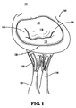
図1は正常な僧帽弁101を示す。図1に示すように、僧帽弁101は僧帽輪105、前僧帽弁小葉110、後僧帽弁小葉115、腱索120、内側乳頭筋135、及び、外側乳頭筋140からなる。「僧帽弁輪」という語は、左心房床と連続している弁小葉付着部の楕円領域のことを指して言う。僧帽弁輪05は前僧帽輪125と後僧帽輪10から構成されている。僧帽輪105はサドル状で、サドルの基部が内側と外側の位置にある。前僧帽輪125に付着しているのが前僧帽弁小葉110であり、後僧帽輪130に付着しているのが後僧帽弁小葉115である。前僧帽弁小葉110及び後僧帽弁小葉115が合流している領域は外側交連145及び内側交連150と表現されている。
FIG. 1 shows a normal mitral valve 101. As shown in FIG. 1, the mitral valve 101 includes a
正常な僧帽弁では、心房圧が心室圧を超過すると、弁小葉が心室の中に向けて解放状態となる。心室圧が上昇すると、小葉が合流して閉鎖し、弁輪の領域を覆う。よって、図1に示す図では、心拡張期は前僧帽弁小葉110及び後僧帽弁小葉115が開いて、僧帽弁101を通して血液が流動することができるようにする。これとは逆に、心収縮期には、前僧帽弁小葉110及び後僧帽弁小葉115は互いに重なり合って僧帽弁101を閉鎖し、血液の逆流すなわち血液の環流が左心房に流入するのを阻止する。
In a normal mitral valve, when the atrial pressure exceeds the ventricular pressure, the valve leaflets are released into the ventricle. As ventricular pressure rises, the leaflets meet and close, covering the area of the annulus. Thus, in the view shown in FIG. 1, during diastole, the
僧帽弁と同様に、房室弁の機能は小葉、腱索、及び、乳頭筋などの複数の構成要素の複雑な相互作用を含んでいる。これら構成要素のうちの1つが、又は、複雑な相互作用の諸機能のうちの1つが不全状態となると、僧帽弁還流を生じる結果となることがある。例えば、小葉組織が過剰であったり、小葉組織が不適切であったり、又は、小葉の運動が制限されると、僧帽逆流を生じる恐れがある。長期化した僧帽弁逆流、深刻な僧帽弁逆流、又は、その両方が生じた結果として左心室の負担過剰が起こる。左心室を酷使すると左心室拡大や機能不全に至り、心不全を生じることがある。僧帽弁逆流は、矯正されなければ致命傷となる恐れのある進行性疾患である。 Like the mitral valve, the function of the atrioventricular valve involves a complex interaction of multiple components such as the leaflets, chordae, and papillary muscles. Failure of one of these components, or one of the complex interaction functions, can result in mitral valve reflux. For example, excessive lobular tissue, inappropriate lobular tissue, or limited lobular movement can cause mitral reflux. Left ventricular overload occurs as a result of prolonged mitral regurgitation, severe mitral regurgitation, or both. Overuse of the left ventricle can lead to left ventricular enlargement or dysfunction, resulting in heart failure. Mitral regurgitation is a progressive disease that can be fatal if not corrected.
依然として虚血性僧帽逆流(IMR)の外科治療の足枷となっているのは、最適とは言えない臨床結果と長期にわたる非常に高い致死性である。僧帽弁修復術は僧帽逆流を起こす大半の原因疾患については弁置換術よりも好ましいが、IMR症状を有する患者には依然として挑戦課題でしかない。現況では、IMR疾患に対する標準的僧帽修復術の代表的なものは小リングを用いた弁輪形成術である。この難しい疾患に対処する目的で、より新規な修復術が提案されている。 Still the footsteps of surgical treatment of ischemic mitral regurgitation (IMR) are suboptimal clinical outcomes and long-lasting very lethality. While mitral valve repair is preferable to valve replacement for most causative diseases that cause mitral regurgitation, it remains a challenge for patients with IMR symptoms. At present, a typical example of standard mitral repair for IMR disease is annuloplasty with a small ring. Newer repairs have been proposed to address this difficult disease.
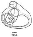
ハイド(Hyde)に交付された米国特許第7,087,064号(特許文献1)は僧帽弁逆流治療のための従来技術を記載しており、具体例として、経皮的に配置することができるリガチャ(ligature)の使用が挙げられている。図2は、特許文献1のリガチャが僧帽弁に配置された図である。特許文献1に記載されているように、リガチャは経皮的に血管、静脈、又は、動脈を通して心臓の中に配置される。配置後は、リガチャが僧帽弁の両側の僧帽弁線維弁輪に取付けられる。直径が僧帽弁輪のものよりも小さいリガチャの設置は、僧帽弁の周辺を窄ませ、整形し、又は、収縮させるように作用する。 U.S. Pat. No. 7,087,064 issued to Hyde describes prior art for mitral regurgitation treatment, and as a specific example, a ligature that can be placed percutaneously ( ligature). FIG. 2 is a diagram in which the ligature of Patent Document 1 is arranged on the mitral valve. As described in U.S. Pat. No. 6,057,059, ligatures are placed percutaneously into the heart through blood vessels, veins or arteries. After deployment, the ligature is attached to the mitral valve annulus on both sides of the mitral valve. Placing a ligature that is smaller in diameter than that of the mitral annulus acts to squeeze, shape, or contract the periphery of the mitral valve.
特許文献1の受動的なリガチャによる方法の代替例として、中隔−側面弁輪締付け処置(SLAC: Septal-Lateral Annular Cinching)に中央経弁輪縫合を併用した試験的技術が或る疑いのない効果を示している。SLACは、心臓機能不全を治療しながら鬱血性心不全を回避する従来技術と比べて潜在的な利点を提示している。僧帽弁治療の従来の取組みと装置は、弁の正常な機能を改変する結果となることが多かった。例えば、弁の後小葉を固定することにより、従って、双小葉の弁を単小葉の弁に変換することにより、僧帽弁逆流を治療する。非制限的な例として、リングを用いた弁輪形成術は急性虚血性僧帽逆流を阻止することができるが、弁輪形成術はまた、正常な僧帽弁輪及び後小葉の力動を廃する。リングを用いた弁輪形成術及びその他の類似技術は僧帽弁の性能劣化の原因となる恐れがあり、例えば、弁輪の柔軟性喪失や経弁勾配の発生などの性能劣化がある。この種の技術は僧帽弁の正常な機能を変更又は変化させる。他方で、SLACは僧帽弁及び僧帽弁小葉の生理学的力動を保存するために実施される。更に、SLACは、適切な機能を得るために生理学的僧帽弁輪組織形態を維持するのに役立つ。 As an alternative to the passive ligature method of Patent Document 1, there is no doubt that there is a test technique using a central trans-annular suture in combination with a septal-lateral annular cinching (SLAC). It shows the effect. SLAC offers potential advantages over the prior art that avoids congestive heart failure while treating cardiac dysfunction. Traditional approaches and devices for mitral valve treatment often resulted in altering the normal function of the valve. For example, mitral regurgitation is treated by fixing the leaflet behind the valve, and thus converting the bilobular valve to a single leaflet valve. As a non-limiting example, annuloplasty with a ring can prevent acute ischemic mitral regurgitation, but annuloplasty also eliminates normal mitral annulus and posterior lobular force dynamics. To do. Annuloplasty using a ring and other similar techniques can cause degradation of the performance of the mitral valve, for example, performance degradation such as loss of flexibility of the annulus and the occurrence of a transvalvular gradient. This type of technique alters or changes the normal function of the mitral valve. On the other hand, SLAC is performed to preserve the physiological force of the mitral valve and mitral leaflet. In addition, SLAC helps maintain physiological mitral annulus tissue morphology for proper functioning.
近年の研究の1つが動物の心臓の急性虚血性僧帽逆流を治療する目的で従来のSLAC施術の採用に重点を置いており、SLAC術により供与される潜在的な利点を示す。ティー・エー・ティメック(Timek)ほか著、胸部心臓血管外科ジャーナル2002年5月刊行123(5)号、881〜888頁の論文を参照のこと。研究結果は、僧帽弁輪の中隔−側面直径寸法が平均で22%(+/−10%)低減することを示している。この研究の結論を言うと、上述のように寸法低減することで急性虚血性僧帽逆流を緩和すると同時に、僧帽弁輪及び後小葉の力動をほぼ正常にすることができるようになる。この研究の前提条件となっているのは、SLACが他の医療術の付属技術であれ、単独であれ、いずれにせよ、虚血性僧帽逆流の外科治療の簡単な方法の代表的なものであり、生理学的弁輪機能及び小葉機能を保存するのに役立つことである。 One of the recent studies has focused on adopting conventional SLAC procedures for the purpose of treating acute ischemic mitral reflux in the heart of animals and demonstrates the potential benefits offered by SLAC procedures. See T. A. Timek et al., The Journal of Thoracic Cardiovascular Surgery, May 2002, Issue 123 (5), pages 881-888. Research results show that the septal-lateral diameter dimension of the mitral annulus is reduced by an average of 22% (+/− 10%). The conclusion of this study is that dimensional reduction as described above can alleviate acute ischemic mitral regurgitation, while at the same time making mitral annulus and posterior lobular force dynamics nearly normal. Prerequisite for this study is whether SLAC is a simple method of surgical treatment of ischemic mitral reflux, whether it is ancillary to other medical procedures or alone. Yes, to help preserve physiological annulus function and leaflet function.
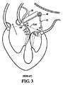
これとは別な従来のSLAC術がレアリヴァスケズ(Realyvasquez)に交付された米国特許出願公開第2005/0143811号(特許文献2)に開示されている。は、経皮配備を利用してSLACを実施することを開示している。図3は特許文献2に開示されているSLAC術を実施するために利用される従来の装置を示す図である。図3に示す装置50は特許文献2には、左右心房間の隔壁を貫き通す経皮血管内カテーテルを利用して配送されるものと記載されている。装置の配送が完了してしまうと、2個のワイヤ補強式ステント52が配備され、拡張を許容される。ステント52の前部は、複数の歯がワイヤに固定された状態で、一時的に弁輪に取付けられる。後部は、同様の複数の歯を使って後弁輪に固定される。ステントが適切な位置にくると、血管内を配送された係留具が前後両方の弁輪取付け位置について、ワイヤがそれぞれの位置で再補強される。
Another conventional SLAC technique is disclosed in US Patent Application Publication No. 2005/0143811 (Patent Document 2) issued to Realyvasquez. Discloses performing SLAC using transdermal deployment. FIG. 3 is a diagram showing a conventional apparatus used for performing the SLAC technique disclosed in Patent Document 2. In FIG. The device 50 shown in FIG. 3 is described in Patent Document 2 as being delivered using a percutaneous intravascular catheter that penetrates the septum between the left and right atria. Once the device has been delivered, two wire reinforced
特許文献2に開示されている装置50はラチェット機構60を含んでいる。このラチェット機構は、装置50を配送したカテーテルによって作動状態にされる。特許文献2は、ラチェット機構60に取付けられたカテーテルが反時計方向に回転させられて、ラチェット機構60を作動状態にすると説明している。ラチェット機構60の回転は、2個のワイヤ補強式ステント52を装置50の中心に向けて移動させるように作動する。特許文献2は、前後両方の弁輪に取付けられた2個のワイヤ補強式ステント42の間の距離を短くすることが、中隔−側面弁輪締付け処置の効果を達成するのに役立つことを開示している。
The device 50 disclosed in Patent Document 2 includes a
先行技術の装置はいずれもそれぞれの意図した目的には好適であるが、多数の欠陥を有しており、介在する心臓病医、心臓血管外科医、及び、このような医者が手術を施す患者の要求に適わずにいる。明らかに、欠陥のある心臓弁を矯正する目的で、観血を最小に抑える装置及びこれに付随する技術の必要が依然として存在する。特に、房室弁の中隔−側面直径距離を制限する目的で、観血を最小に抑える装置及びこれに付随する技術が必要である。更に、観血を最小に抑える装置及びこれに付随する技術は、拍動する心臓に実装することができなければならない。胸腔鏡による内視術及び経皮術を含む種々の方法で実施することができる、房室弁の中隔−側面直径を制限することができる装置を供与することは多いに望ましい。 All of the prior art devices are suitable for their intended purpose, but have a number of deficiencies, and include intervening cardiologists, cardiovascular surgeons, and patients on whom such doctors operate. You are not meeting your requirements. Clearly, there is still a need for devices and associated techniques that minimize open blood for the purpose of correcting defective heart valves. In particular, for the purpose of limiting the septal-lateral diameter distance of the atrioventricular valve, there is a need for a device that minimizes blood viewing and the associated techniques. In addition, devices that minimize open blood and the associated techniques must be able to be implemented in the beating heart. It is often desirable to provide a device that can limit the septal-lateral diameter of the atrioventricular valve, which can be performed in a variety of ways, including thoracoscopic endoscopy and percutaneous surgery.
よって、弁性能を向上させる装置及び方法を提供するのが有利である。 Thus, it would be advantageous to provide an apparatus and method that improves valve performance.
更に、心臓弁の寸法を制限する装置及び方法を提供するのが有利である。 Furthermore, it would be advantageous to provide an apparatus and method for limiting the size of a heart valve.
また、拍動する心臓の心臓弁の直径を制限することにより僧帽弁逆流を矯正する装置及び方法を提供することが有利である。 It would also be advantageous to provide an apparatus and method for correcting mitral regurgitation by limiting the diameter of the beating heart valve.
更に、観血を最小に抑える仕方で実装される拍動する心臓の心臓弁の直径を制限する装置及び方法を提供するのが有利である。 In addition, it would be advantageous to provide an apparatus and method for limiting the diameter of the heart valve of a beating heart that is implemented in a manner that minimizes open blood.
更にまた、拍動する心臓の心臓弁の直径を制限する目的で、心臓の外側から長いアーム又は操縦可能なニードルを使って配送される装置を提供するのが有利である。 Furthermore, it is advantageous to provide a device that is delivered from the outside of the heart using a long arm or steerable needle for the purpose of limiting the diameter of the heart valve of the beating heart.
更に、拍動する心臓の房室弁の中隔−側面直径を減少させることができる装置を提供するのが有利である。 In addition, it would be advantageous to provide a device that can reduce the septal-lateral diameter of the beating heart atrioventricular valve.
更にまた、心臓弁の直径をより長期にわたって減少させることができる装置を提供するのが有利である。 Furthermore, it would be advantageous to provide a device that can reduce the diameter of the heart valve over a longer period of time.
また、以前に施された外科手術で使用された構成要素に容易に接近して、医者が後日に心臓弁の寸法を更に制限することができるようにした、心臓弁の寸法を減少させる方法を提供するのが有利である。 There is also a method for reducing the size of a heart valve that allows easy access to components used in previously performed surgery, allowing the physician to further limit the size of the heart valve at a later date. It is advantageous to provide.
更に、より長期に亘って寸法減少処置を繰返すことができる、心臓弁の寸法を減少させる方法を提供するのが有利である。 In addition, it would be advantageous to provide a method for reducing the size of a heart valve that allows the size reduction procedure to be repeated over a longer period of time.
更にまた、心臓弁の生理学的力動を変えることなく、拍動する心臓弁の組織形態を改善する装置及び方法を提供するのが有利である。 Furthermore, it would be advantageous to provide an apparatus and method that improves the tissue morphology of a beating heart valve without altering the physiological force dynamics of the heart valve.
本発明は、心臓弁の寸法を制御する方法及び装置を説明している。本発明の例示の実施形態は、心臓弁の組織形態を改善する方法を提示している。この方法はまず、心臓の組織構成要素上の第1目標部位にアンカー固定構成要素を取付ける処置を含んでいる。次に、心臓の組織構成要素上の第2目標部位にロック構成要素が取付けられる。この後、引張り部材がアンカー固定構成要素に連結されてから、引張り部材がロック構成要素に連結される。次に、引張り部材を作動させることで、第1目標部位と第2目標部位の間の距離が調節される。続いて、ロック構成要素を使って、引張り部材が適所に固定される。 The present invention describes a method and apparatus for controlling the dimensions of a heart valve. Exemplary embodiments of the present invention present a method for improving the tissue morphology of a heart valve. The method first includes the step of attaching an anchoring component to a first target site on the cardiac tissue component. Next, a locking component is attached to a second target site on the cardiac tissue component. Thereafter, the tension member is coupled to the anchoring component and then the tension member is coupled to the locking component. Next, the distance between the 1st target part and the 2nd target part is adjusted by operating a tension member. Subsequently, the tension member is secured in place using the locking component.
本発明の上述の目的、特徴、及び、利点と、その他の目的、特徴、及び、利点とは、添付の図面に関連づけて後段の明細書を読めば、一層明瞭となる。 The above objects, features and advantages of the present invention and other objects, features and advantages will become clearer when the subsequent specification is read in conjunction with the accompanying drawings.
本発明は、弁組織形態を改善することを目的とした、観血を最小に抑えた装置及び方法を提供することにより、先行技術の欠点に対処するものである。本件に開示されている弁組織形態を改善する医療装置及び医療法は、心臓の弁の内側の2つの目標部位の間の距離を減少させることができるようにするものである。心臓の弁の内側の2つの目標部位の間の距離を減少させることで、弁性能を向上させ、改修し、又は、その両方を実施することができる。 The present invention addresses the shortcomings of the prior art by providing a minimally open device and method aimed at improving valve tissue morphology. The medical devices and methods that improve the valve tissue morphology disclosed herein allow the distance between two target sites inside a heart valve to be reduced. By reducing the distance between the two target sites inside the heart valve, valve performance can be improved and / or modified.
本発明の例示の実施形態は弁組織形態を向上させる方法を提供する。この方法はまず、心臓の組織構成要素上の第1目標部位にアンカー固定構成要素を取付ける処置を含んでいる。次に、心臓の組織構成要素上の第2目標部位にロック構成要素が取付けられる。この後、引張り部材がアンカー固定構成要素に連結されてから、引張り部材はロック構成要素に連結される。次に、引張り部材を作動させることで、第1目標部位と第2目標部位の間の距離が調節される。続いて、ロック構成要素を使って、引張り部材が適所に固定される。 Exemplary embodiments of the present invention provide a method for improving valve tissue morphology. The method first includes the step of attaching an anchoring component to a first target site on the cardiac tissue component. Next, a locking component is attached to a second target site on the cardiac tissue component. Thereafter, the tension member is coupled to the anchoring component and then the tension member is coupled to the locking component. Next, the distance between the 1st target part and the 2nd target part is adjusted by operating a tension member. Subsequently, the tension member is secured in place using the locking component.
弁の組織形態を改善する方法の例示の実施形態を利用して僧帽弁逆流を治療することができるが、場合によっては、僧帽弁逆流を矯正することができる。例えば、また、だからと言ってそれに限定するわけではないが、第1目標部位と第2目標部位の間の距離を短縮することで、僧帽弁の中隔−側面直径(septal-lateral diameter)を減じることができる。このように僧帽弁の中隔−側面直径を減じることで、心収縮期には僧帽小葉を重なり合わせることができるようにすることで、僧帽弁性能を無欠にするのを支援することができる。更に、中隔−側面直径を減じることで、心収縮期に左心室から左心房に血液が環流するのを阻止し、又は、そのような還流を緩和するのを助けることができる。 While exemplary embodiments of methods for improving valve tissue morphology can be utilized to treat mitral regurgitation, in some cases mitral regurgitation can be corrected. For example, but not necessarily, it is possible to reduce the distance between the first target site and the second target site so that the septal-lateral diameter of the mitral valve Can be reduced. In this way, reducing the septal-lateral diameter of the mitral valve allows it to overlap with the mitral leaflets during systole, thereby assisting in mitral valve performance. Can do. In addition, reducing the septal-lateral diameter can prevent blood from circulating from the left ventricle to the left atrium during systole or help to alleviate such reflux.
これに加えて、僧帽弁の組織形態を改善するために、本発明が提供することのできる方法及び装置を利用して、僧帽弁以外の各種心臓弁の性能を向上させることができる。弁組織形態を向上させる方法の例示の実施形態を利用して、大動脈弁逆流を治療し、場合によっては、大動脈弁逆流を矯正することができる。弁組織形態を改善する方法の変形実施形態を利用して、肺動脈弁及び三尖弁の性能を向上させることができる。 In addition, in order to improve the tissue morphology of the mitral valve, the methods and apparatus that the present invention can provide can be used to improve the performance of various heart valves other than the mitral valve. An exemplary embodiment of a method for improving valve tissue morphology can be utilized to treat aortic valve regurgitation and possibly correct aortic regurgitation. Variations of the method for improving valve tissue morphology can be utilized to improve the performance of pulmonary and tricuspid valves.
本発明による弁の組織形態を改善する方法は、拍動する心臓に実施することができる、観血を最小に抑えた処置である。更に、本発明による弁の組織形態を改善する方法は、胸腔鏡を使った内視による配備、血管内配送配備、経皮配備などを含む種々の処置又はこれらの処置の組合せにより実施される。本件に記載されている、弁の組織形態を改善する方法及びその方法に付随する装置の実施形態は具体例であり、代表例として提示されているにすぎないことを、当業者は認識すべきである。 The method for improving valve tissue morphology according to the present invention is a minimally invasive procedure that can be performed on a beating heart. Furthermore, the method for improving the tissue morphology of the valve according to the present invention is performed by various procedures or combinations of these procedures including endoscopic deployment using a thoracoscope, intravascular delivery deployment, percutaneous deployment, and the like. One of ordinary skill in the art should recognize that the embodiments of the method for improving valve tissue morphology and the devices associated therewith described herein are exemplary and are presented only as representative examples. It is.
本発明の例示の実施形態では、近位端部及び遠位端部が設けられているアンカー固定構成要素を備えている締付け装置が提示されている。アンカー固定構成要素の近位端部には、心臓の組織構成要素と連結した取付け具が設けられている。ロック構成要素にも、心臓の組織構成要素と連結した取付け具が設けられている。締付け装置は引張り部材も備えている。アンカー固定構成要素は心臓の組織構成要素上の第1目標部位に設置することができるようになっており、ロック構成要素は心臓の組織構成要素上の第2目標部位に設置することができるようになっており、引張り部材はアンカー固定構成要素及びロック構成要素の両方に連結される。引張り部材は第1目標部位と第2目標部位の間の距離を調節するように作動されてから、ロック構成要素によって固定される。 In an exemplary embodiment of the invention, a tightening device is provided that includes an anchoring component that is provided with a proximal end and a distal end. A proximal end of the anchoring component is provided with a fitting connected to the heart tissue component. The locking component is also provided with a fitting connected to the cardiac tissue component. The clamping device also includes a tension member. The anchoring component can be placed at a first target site on the heart tissue component, and the locking component can be placed at a second target site on the heart tissue component. And the tension member is connected to both the anchoring component and the locking component. The tension member is actuated to adjust the distance between the first target site and the second target site and then secured by the locking component.
例示の実施形態では、引張り部材を作動させるのに引張り部材を引張ることで、第1目標部位と第2目標部位の間の距離を減じる態様で距離調節するように図っている。例えば、また、限定するわけではないが、医者が引張り部材を引張れば、距離を減じるとともに引張り部材を適所に固定することができる。 In the illustrated embodiment, the pulling member is pulled to actuate the pulling member to adjust the distance in a manner that reduces the distance between the first target site and the second target site. For example, but not limited to, if the physician pulls the tension member, the distance can be reduced and the tension member can be secured in place.
締付け装置の例示の実施形態はアンカー固定構成要素、ロック構成要素、及び、引張り部材をそれぞれ1個以上ずつ有している。これら構成要素材は、本発明による弁の組織形態を改善する方法で活用される。例示の実施形態では、締付け装置の種々の構成要素材は生体適合性素材から構成されている。生体適合性素材の具体例として、生体適合性金属又は生体適合性重合体が挙げられるが、これらに限定されない。本発明の範囲から外れなければ、広範な生体適合性素材から締付け装置が構成されてもよいことを、当業者は認識すべきである。 An exemplary embodiment of a clamping device has one or more anchoring components, locking components, and tension members. These component materials are utilized in the method of improving the tissue morphology of the valve according to the present invention. In the illustrated embodiment, the various components of the clamping device are constructed from a biocompatible material. Specific examples of biocompatible materials include, but are not limited to, biocompatible metals or biocompatible polymers. Those skilled in the art should recognize that the clamping device may be constructed from a wide range of biocompatible materials without departing from the scope of the present invention.
アンカー固定構成要素は組織に取付け可能な装置である。例示の実施形態では、アンカー固定構成要素は、近位端部と遠位端部とを有している。用語「近位」は、本明細書において、ある位置が別の位置よりも比較的近くにあることを説明するのに使用され、複数の近くの位置全体の範囲を含み、ある位置が別の位置に直接隣接し又は当接することを含む。用語「遠位」は、本明細書において、ある位置が別の位置から比較的遠くにあることを説明するのに使用される。従って、本明細書において、用語「近位」及び「遠位」は、空間的関係を言及するのに使用され、血液の流れの上流側又は下流側の位置を説明するために使用されているのではない。 An anchoring component is a device that can be attached to tissue. In the illustrated embodiment, the anchoring component has a proximal end and a distal end. The term “proximal” is used herein to describe that a location is relatively close to another location, including a range of a plurality of nearby locations, where one location is another Including directly adjacent or abutting a position. The term “distal” is used herein to describe that one location is relatively far from another location. Accordingly, in this specification, the terms "proximal" and "distal" are used to refer to spatial relationships and are used to describe positions upstream or downstream of blood flow. Not.
例示の実施形態では、アンカー固定構成要素の近位端部は、組織に係合させることができることが可能である。例えば、また、限定するわけではないが、アンカー固定構成要素の近位端部の面又は棒状部は、アンカー固定構成要素の本体部に対して或る角度を成している。この面又は棒状部の角度により、面又は棒状部に組織構成要素に対する接合部すなわち掴み部を有することができる。変形実施形態では、アンカー固定構成要素は、組織面を刺し通すことができる傘型の近位端部を有する。また別な実施形態は、組織面に埋め込むことができる脚部を有するアンカー固定構成要素である。アンカー固定構成要素の近位端部は、組織面に取付けることができる種々の構成要素材で代用されることを、当業者は認識すべきである。 In an exemplary embodiment, the proximal end of the anchoring component can be capable of engaging tissue. For example, and without limitation, the proximal end face or bar of the anchoring component is at an angle to the body of the anchoring component. Depending on the angle of the face or bar, the face or bar can have a joint or grip for tissue components. In an alternative embodiment, the anchoring component has an umbrella-shaped proximal end that can pierce the tissue surface. Another embodiment is an anchoring component having legs that can be implanted in a tissue surface. One skilled in the art should recognize that the proximal end of the anchoring component may be substituted with various component materials that can be attached to the tissue surface.
例示の実施形態では、固定システムの中心部は、ロッド、ワイヤ、又はその他の多数の好適な細長い部材である。アンカー固定構成要素の遠位側は、係合部材又は係合面である。このような係合部材は、引張り部材又はロッドと連結するように設計されている。連結部材の好ましい実施形態は、ループ、ネジ留め面、フック、クランプ、結合用開口、又はその他の多数の好適な構成要素である。アンカー固定構成要素は、カテーテルを使って血管内を配送されてもよいし、又は、長いアーム式配送装置又は操縦可能なニードルを使って心臓チャンバの出入窓を通して配送されてもよい。本発明の各方法を実施するために使用される装置及び器具は、実施態様ごとに異なっていてもよいことを、当業者は認識すべきである。例えば、長いアーム装置は、或る部材を観血を最小に抑えて配送することができる多数の異なる種類の装置で代用することができることが、当業者には分かるだろう。 In the illustrated embodiment, the central portion of the fixation system is a rod, wire, or many other suitable elongated members. The distal side of the anchoring component is an engagement member or engagement surface. Such engagement members are designed to couple with a tension member or rod. Preferred embodiments of the connecting member are loops, screw faces, hooks, clamps, coupling openings, or many other suitable components. The anchoring component may be delivered intravascularly using a catheter, or it may be delivered through an entry window in the heart chamber using a long arm delivery device or a steerable needle. One skilled in the art should recognize that the apparatus and instruments used to perform each method of the present invention may vary from embodiment to embodiment. For example, those skilled in the art will appreciate that long arm devices can be substituted with many different types of devices that can deliver a member with minimal open blood.
図4Aは、本発明によるアンカー固定構成要素又は固定装置400Aの例示の実施形態を示す図である。図4Aに示すアンカー固定構成要素400Aは、その近位端部に取付け部材405を有している。この取付け部材405は、組織構成要素に係合することができ且つそれを刺し通すことができる。図4Aに示す例示の実施形態では、取付け部材405は、傘型構造体である。固定装置400Aの中心部分は、ロッド部材410である。
FIG. 4A is a diagram illustrating an exemplary embodiment of an anchoring component or anchoring device 400A according to the present invention. The anchoring component 400A shown in FIG. 4A has a mounting
図4Aに示す固定装置400Aはまた、その遠位端部に係合部材415を有している。この係合部材415は、引張り部材又はその他の媒体を連結し、その終端部となり、又は、それを固定することができる。図4Aの例示の実施形態に示すように、係合部材415はピグテール(pigtail)形状部材であるのがよい。ピグテール形状部材が有利である理由は、ピグテール形状部材を組織構成要素の中を通して挿入した後、係合部材415を展開させることができるからである。例示の実施形態では、係合部材415を実質的に平坦な形態で組織構成要素の中に挿入し、ピグテール形状に展開させる。当業者は、本発明の範囲から逸脱しない限り、係合部材415が種々の形態を有していてもよいことを認識すべきである。
The fixation device 400A shown in FIG. 4A also has an
図4Bは、本発明による変形実施形態のアンカー固定構成要素400Bを示す図である。図4Bに示す変形実施形態のアンカー固定構成要素400Bは、その近位端部に、ロッド形状の部材である取付け部材420を有している。このロッド形状の取付け部材420は、組織面と接合される。アンカー固定構成要素400Bの例示の実施形態は、2つの係合部材430、435を有している。係合部材430、435は、図4Bに示すように、引張り部材に結合させることができるピグテール形状部材であるのがよい。限定するわけではないが、一例において、いったん係合部材430を心臓チャンバ内に位置決めしたら、係合部材430を引張り部材に結合させ、係合部材435を上記引張り部材と異なる引張り部材に結合させる。図4A及び4Bに示すアンカー固定構成要素400A、400Bの2つの実施形態は代表例として提示されており、アンカー固定構成要素は種々の変形例の装置で実現されてもよいことを、当業者は認識すべきである。
FIG. 4B shows an alternative
図5は、本発明によるアンカー固定構成要素の係合部材505の、展開前における例示の実施形態を示す。図5に示す係合部材505は、実質的に平坦な形状で配送されることが可能である。係合部材505の例示の実施形態は、操縦可能なニードル内で又はその他適当な配送装置内で配送されるのがよい。このように、係合部材505は実質的に平坦な形状で組織構成要素に刺し通すことが可能である。いったん係合部材505を組織構成要素に刺し通したら、係合部材505を展開させるのがよい。例えば、限定するわけではないが、係合部材505を左心室から左心房の中まで後僧帽弁輪を刺し通す。例示の実施形態では、係合部材505が左心房内に位置したら、係合部材505を管腔の中から押出し、ピグテール形状部材を形成する。このピグテール形状部材は、後で引張り部材を係合部材505に取付けるのに必要な構造を有している。
FIG. 5 shows an exemplary embodiment of the anchoring
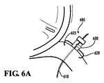
図6Aは、本発明の例示の実施形態によるロック構成要素605の例示の実施形態を示す図である。例示の実施形態では、ロック構成要素605は心臓の外面に係合し、又は、三角形部位又はその他の領域の軟骨に係合する。ロック構成要素605の係合を可能にする刺し通し構成要素は、フック、傘部、接合面、複数の拡張可能な脚部、又は、その他適当な構成要素である。ロック構成要素605は、引張り部材610を固定するロックシステムを有し、このロックシステムは、引張り部材610に係合している時に引張り部材610の移動を阻止して、弁の直径を制限するのがよい。図6Aに示す例示の実施形態では、ロック構成要素605は、ピン圧縮システムを構成するロックシステム630を有している。図示のように、ロックシステム630のピンは、引張り部材610を固定したりかかる固定を解除したりするように移動可能に位置決めされるのがよい。
FIG. 6A is a diagram illustrating an exemplary embodiment of a
例示の実施形態では、ロック構成要素605は、心臓の組織構成要素上の多数の適当な目標部位のところに取付けられる。例えば、限定するわけではないが、一実施形態では、ロック構成要素605は、アンカー固定構成要素が僧帽弁輪に取付けられている箇所と実質的に反対側に位置する僧帽弁輪上の目標部位に取付けられる。ロック構成要素605は、組織構成要素を刺し通す刺し通し構成要素、例えば620、625を有し、刺し通し構成要素は、ロック構成要素605を組織構成要素に固定する。図6Aに示す例示の実施形態では、刺し通し構成要素620、625は、前僧帽弁輪の近くで且つ大動脈壁に隣接した左心房壁を刺し通す。
In the illustrated embodiment, the
ロック構成要素605は、引張り部材610が通ることができる導管を有している。例示の実施形態では、引張り部材610は、ロック構成要素605の中に通され、左心房に入る。この例示の実施形態では、引張り部材610は、アンカー固定構成要素400A(図4A)の係合部材415に連結される係合遠位端部を有している。引張り部材610をアンカー固定構成要素400Aに結合させたら、引張り部材610を、アンカー固定構成要素400A(図4A)とロック構成要素605との間の距離が減少するように前進させる。この距離を所望量だけ減少させた後、ロック構成要素605のロックシステム630は、引張り部材610を適所に固定する。例示の実施形態では、本発明に従って弁形態を改善する方法を実施する外科医は、引張り部材610を患者の体外の位置から引張り、引張り部材610をロック構成要素605で適所に固定する。
The
例示の実施形態では、ロック構成要素605による固定を解除することも可能である。従って、ロック構成要素605とアンカー固定構成要素400Aとの間の距離を後で変更することを望むならば、引張り部材610のロック構成要素605による固定を解除する。限定しない例では、引張り部材610を前進させ、ロック構成要素605とアンカー固定構成要素400Aとの間の距離を更に減少させ、引張り部材を再び適所に固定させる。
In the illustrated embodiment, the
図6Bは、本発明の例示の実施形態によるロック構成要素605の変形実施形態を示す図である。図6Bに示すように、ロック構成要素605の変形実施形態は、引張り部材610を前進させるネジ構成要素615を組込んでいる。それにより、外科医は、ネジ構成要素615を患者の体外の位置から前進させて、引張り部材を前進させ、ロック構成要素605とアンカー固定構成要素400A(図4A)との間の距離を減少させることができる。引張り部材610を所望の距離だけ前進させたとき、ネジを解放する。次いで、静止したネジ構成要素615は、引張り部材610をロックして維持する。加えて、ネジ構成要素615に再び接触して、引張り部材610を更に前進させ、引張り部材610を新しい位置にロックしてもよい。
FIG. 6B is a diagram illustrating a modified embodiment of the
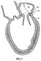
図7は、本発明のアンカー固定構成要素705の例示の実施形態を示す図である。図7に示す例示の実装例では、アンカー固定構成要素705が後僧帽弁輪720を貫いて移植されている。例えば、また、限定するわけではないが、アンカー固定構成要素705は、カテーテルを使って血管内を配送される。更に、アンカー固定構成要素705を圧縮形態で配送し、後で、適所でいったん展開させる。限定しない例では、アンカー固定構成要素705を左心室の中に配送する。次に、アンカー固定構成要素705を目標部位のところで左心室から後僧帽弁輪720に挿入する。従って、アンカー固定構成要素705の係合部材710を目標部位のところで後僧帽弁輪720に刺し通す。係合部材710が後僧帽弁輪を刺し通して左心房730に入ったら、アンカー固定構成要素705の取付け部材715を後僧帽弁輪720に取付ける。このように、アンカー固定構成要素705が後僧帽弁輪720の上に引掛けられ、係合構成要素710が左心房730の中に突出する。
FIG. 7 is a diagram illustrating an exemplary embodiment of an
弁の形態を改善する方法の変形実施形態では、アンカー固定構成要素705を左心房730の中を通して配送する。限定しない例では、アンカー固定構成要素705をカテーテルに取付け、左心房730の中に経皮的に配置する。アンカー固定構成要素705を左心房730の中に導入した後、アンカー固定構成要素705を目標部位のところで後僧帽弁輪720に刺し通す。例示の実施形態では、アンカー固定構成要素705の取付け部材715を目標部位のところで後僧帽弁輪720に刺し通し、左心室の中に突出させる。このように、アンカー固定構成要素705を目標部位のところで後僧帽弁輪720の上に引掛ける。
In an alternative embodiment of the method for improving valve morphology, anchoring
図7に示す例示の実施形態が、本発明によるアンカー固定構成要素の移植の一例を示すに過ぎないことを、当業者は認識すべきである。例えば、限定するわけではないが、僧帽弁の後側に関して、アンカー固定構成要素を後僧帽弁輪の上又はその近位の心筋の上の任意の箇所に配置することが可能である。僧帽弁の前側に関して、アンカー固定構成要素を前僧帽弁輪の上、それに近接した心筋の上、又は前僧帽弁輪に近接した線維性三角形領域の上の任意箇所に配置することが可能である。 Those skilled in the art should recognize that the exemplary embodiment shown in FIG. 7 is merely an example of implantation of an anchoring component according to the present invention. For example, without limitation, with respect to the posterior side of the mitral valve, the anchoring component can be placed anywhere on the posterior mitral annulus or on the proximal myocardium. With respect to the anterior side of the mitral valve, the anchoring component can be placed anywhere on the anterior mitral annulus, on the myocardium adjacent to it, or on the fibrous triangular region adjacent to the anterior mitral annulus Is possible.
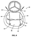
図8は、本発明の例示の実施形態による締付け装置800の例示の実施形態を示す図である。図8に示す締付け装置800の例示の実施形態は、2対のアンカー固定構成要素及びロック構成要素を移植する。図8に示す図は、左心房810の中に突出しているアンカー固定構成要素の係合部材805を示す。ロック構成要素815を種々の目標部位に位置決めすることができ、かかる位置決めは、大動脈弁の近くの左心房810の壁への取付けを含む。図8に示すように、例示の実施形態では、ロック構成要素815は、左心房の外部に位置している。ロック構成要素815は、引張り部材820をロック構成要素815の中の導管の中を通して受入れることが可能である。引張り装置820をロック構成要素815の中に通し、左心房815に入ったら、引張り部材820の係合端部825をアンカー固定構成要素の係合部材805に結合させる。引張り部材820とアンカー固定構成要素820とを結合させた後、引張り部材820を引き、僧帽弁830の中隔−側面直径(septal-lateral diameter)を減少させる。図8に示す例示の実施形態では、かかる減少工程を心臓の外側で行う。当業者なら認識することであるが、胸腔鏡手術による配置、血管内配送による配置、及び経皮的配送な配置等の観血を最小にする多数の技術により、心臓の外側から各処置を実施することができる。加えて、変形実施形態では、本発明の方法の工程を、遠隔装置を介して行ってもよい。例えば、限定するわけではないが、外科医が遠隔装置を使って、引張り部材820を調節するとともに僧帽弁830の中隔−側面直径を減少させることが可能である。
FIG. 8 is a diagram illustrating an exemplary embodiment of a
例えば、また、限定するわけではないが、引張り部材820は、患者の体外で長いアーム装置の中を通って延びるのがよい。従って、外科医は、引張り部材820を患者の体外で引張ることができ、それにより、僧帽弁830の中隔−側面直径を減少させる。
For example, and without limitation, the
本発明により、引張り部材によって連結されているロック構成要素及びアンカー固定構成要素の1つの組又はいくつかの組を房室弁内に実装できることを、当業者は認識すべきである。いくつかの実装例では、引張り部材によって連結されている1組だけのロック構成要素及びアンカー固定構成要素が実装される。一般に、引張り部材によって連結されている2組から10組の範囲のロック構成要素及びアンカー固定構成要素が、房室弁内に実装される。 One skilled in the art should recognize that one or several sets of locking and anchoring components connected by a tension member can be implemented within an atrioventricular valve in accordance with the present invention. In some implementations, only one set of locking and anchoring components are implemented that are connected by a tension member. Generally, a range of 2 to 10 sets of locking and anchoring components connected by a tension member are implemented in the atrioventricular valve.
図8に示すように、僧帽弁830は、2個の引張り部材によって連結されている2組のロック構成要素及びアンカー固定構成要素を有している。第2の組は、僧帽弁830の反対側に実装されている。係合部材835は、後僧帽弁輪の係合部材805の反対側に位置決めされている。他方の組と同様、ロック構成要素840は、引張り部材845が通され、引張り部材は、係合部材835に結合されている。図8に示す例示の実施形態では、2組のロック構成要素及びアンカー固定構成要素は、引張り部材820、845が互いに十分平行に延びるように位置決めされている。この形態により、僧帽弁830の直径が減少したときの僧帽弁830の対称性を維持するのを助ける。第1の引張り部材820と同様、第2の引張り部材845は、患者の体外に延ばされ、外科医が引張り部材の体外部分を引張ることによって、中隔−側面直径を減少させることができる。引張り部材820、845の両方を、僧帽弁830の中隔−側面直径を減少させるに十分引張ったら、引張り部材820、845をそれぞれのロック構成要素815、849によって固定する。引張り部材820、845のロックにより、僧帽弁830を所望の寸法に維持することを確保する。
As shown in FIG. 8, the
本発明の例示の実施形態によると、ロック構成要素による固定を解除することができる。このようにして、治療を受けている心臓弁の寸法を再調節することが可能である。限定しない例では、弁の直径を或る量だけ減少させ、引張り部材をロック構成要素によって適所に固定する。次いで、治療を受けている弁の機能レベルを判定する試験を実施するのがよい。機能が所望のレベルにない場合、引張り部材をロック構成要素による固定を解除し、更に引張り、適所に再固定する。従って、本発明の例示の実施形は、比較的長い期間にわたって弁寸法を漸進的に減少させることを可能にする。一実施形態では、患者が、ロック構成要素に接近して引張り部材を更に引くことによって弁直径を更に減少させる追加の外科手術を受けてもよい。 According to an exemplary embodiment of the present invention, the locking component can be unlocked. In this way it is possible to readjust the dimensions of the heart valve undergoing treatment. In a non-limiting example, the diameter of the valve is reduced by a certain amount and the tension member is secured in place by a locking component. A test may then be performed to determine the functional level of the valve being treated. If the function is not at the desired level, the tensioning member is unlocked by the locking component and then pulled and re-fixed in place. Thus, exemplary embodiments of the present invention allow the valve size to be progressively reduced over a relatively long period of time. In one embodiment, the patient may undergo additional surgery that further reduces the valve diameter by pulling on the tension member closer to the locking component.
本発明の締付け装置を、心臓の4個の弁の任意のものに実装することができる。当業者なら認識することであるが、各種の弁は、弁自体に特別な締付け装置の実装を必要とする場合があり、構成要素の配置及び配送を、4個の弁の各々の固有の特性を補償するように変えるのがよい。 The clamping device of the present invention can be implemented on any of the four valves of the heart. Those skilled in the art will recognize that the various valves may require the implementation of a special clamping device on the valve itself, and the placement and delivery of the components is a unique characteristic of each of the four valves. It is better to change to compensate.
図9は、大動脈弁930に実装される本発明による締付け装置900の例示の実施形態を示す図である。図9に示す例示の実施形態の締付け装置900は、大動脈根910の大動脈弁輪905に実装されている。図9の例示の実施形態に示すように、締付け装置900は、大動脈弁輪905に刺し通すアンカー固定構成要素915を有している。大動脈弁輪905のほぼ反対側に、大動脈弁輪905に刺し通すロック構成要素920が設けられる。例示の実施形態では、引張り部材925をロック構成要素920に通してから、引張り部材925をアンカー固定構成要素915の係合部材に結合させる。引張り部材925を係合部材に結合させたら、引張り部材925を、アンカー固定構成要素915とロック構成要素920との間の距離を減少させるように前進させる。引き続いて、引張り部材925をロック構成要素920によって適所に固定する。これにより、大動脈弁の弁膜尖をより完全に閉鎖させることを可能にし、大動脈弁930の機能を改善させることができる。
FIG. 9 is a diagram illustrating an exemplary embodiment of a
図10は、半月弁1020に実装された本発明による締付け装置1000の例示の実施形態を示す平面図である。本発明により可能になる締付け装置1000を、半月弁、大動脈弁、肺動脈弁のいずれかに実装することがでる。図10に示すように、アンカー固定構成要素1005及びロック構成要素1010は、引張り部材1015が半月弁1020の一部を横断するように、半月弁の弁輪上に構成されている。従って、引張り部材1015を前進させると、半月弁1020の直径を減少させる。
FIG. 10 is a plan view showing an exemplary embodiment of a
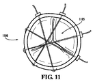
図11は、半月弁1105に実装された本発明による締付け装置1100の例示の実施形態を示す平面図である。図11に示す締付け装置1100は、3組のアンカー固定構成要素、ロック構成要素、及び引張り部材を有している。当業者なら理解することであるが、これらの構成要素の組数とその実装は、処置すべき特定の心臓弁及び解決すべき特定の弁膜状況に応じて変化する。いくつかの実施形態では、心臓弁の機能不全がそれほど深刻ではないことがあり、その場合、心臓弁の直径の望ましい減少量は比較的小さい。このような実施形態では、限られた組の構成要素が、締付け装置に採用される。その他の実施形態では、弁が極めて対称であることが望ましいことがあり、その場合、作動弁の完全な対称性を達成してそれを維持する目的で、複数組の構成要素が配置される。図11に示す例示の実施形態は、3組のロック構成要素、アンカー固定構成要素、及び引張り部材を有する締付け装置が、半月弁に実装されていることを示す。これら3組の構成要素の配置により、半月弁の直径の対称的な減少を確保し、半月弁の機能及び動作の向上を確保する。
FIG. 11 is a plan view illustrating an exemplary embodiment of a
図12は、三尖弁1205に実装された本発明による締付け装置1200の例示の実施形態を示す図である。図12に示す例示の実施形態の締付け装置1200は、三尖弁1205の弁輪1230に実装されている。図12の例示の実施形態に示すように、締付け装置1200は、2個のアンカー固定構成要素1210、1215を有している。僧帽弁に使用される締付け装置の実施形態と同様、三尖弁1205に好適なアンカー固定構成要素1210、1215を種々の異なる仕方で配送することができる。限定するわけではないが、例えば、アンカー固定構成要素を右心室1220までカテーテルを介して経皮的に配送する。アンカー固定構成要素1215を右心室1220の中まで配送したら、アンカー固定構成要素1215を三尖弁1205の弁輪1230に刺し通して、右心房1225の中に突出させる。変形例として、アンカー固定構成要素1215を右心房1225に配送してから、三尖弁1205の弁輪1230に刺し通し、アンカー固定構成要素1215の取付け部材を右心室1220の中に露出させてもよい。
FIG. 12 is a diagram illustrating an exemplary embodiment of a
アンカー固定構成要素を三尖弁1205の弁輪1230と右心室1220との間に取付ける機能に加えて、アンカー固定構成要素を弁輪1230と右心房1225の壁との間に取付けるのがよい。図12に示すように、アンカー固定構成要素1210は、三尖弁1205の弁輪1230と右心房1225との間に取付けられている。アンカー固定構成要素を取付けるこの方法により、追加の配送方法を可能にする。例えば、アンカー固定構成要素1210を、長いアーム装置を介して配送し、移植する。アンカー固定構成要素1210を移植する外科医は、心臓動脈に通じている開口、例えば開口1235の付近にアンカー固定構成要素1210を移植することがないように注意しなければならない。当業者なら認識することであるが、本発明の範囲から逸脱することなしに、アンカー固定構成要素を種々の異なる仕方で配送し且つ移植してもよい。
In addition to attaching the anchoring component between the
ロック構成要素1240は、三尖弁1205の弁輪1230のほぼ反対側に設けられるのがよい。例示の実施形態では、ロック構成要素11240を右心房1225の壁まで長いアーム装置を介して配送する。次いで、ロック構成要素1240を右心房1225の壁に刺し通す。例示の実施形態では、引張り部材1245をロック構成要素1240及び三尖弁1205の弁輪1230に通す。次いで、引張り部材1245をアンカー固定構成要素1210、1215の係合部材に結合させる。引張り部材1245を結合させたら、引張り部材1245を、アンカー固定構成要素1210、1215間とロック構成要素1240との間の距離を減少させるように前進させる。引き続いて、引張り部材1245をロック構成要素1240によって適所に固定する。これにより、三尖弁1205の小葉をより完全に閉鎖させることによって、三尖弁1205の機能を向上させる。
The
図13は、三尖弁1205に実装された本発明による締付け装置1300の例示の実施形態を示す平面図である。図13に示すように、締付け装置1300は、2組のロック構成要素、アンカー固定構成要素、及び引張り部材を有している。しばしば、三尖弁の直径を、三尖弁1205の3枚の小葉の接合線箇所が実質的に不規則になるようないくつかの方向に減少させることによって、不完全な三尖弁を改善する。
FIG. 13 is a plan view illustrating an exemplary embodiment of a
図13に示すように、アンカー固定構成要素1305を三尖弁1205の弁輪の僧帽弁に近い側に配置する。次に、弁輪のほぼ反対側で、アンカー固定構成要素1305を引張り部材1315によってロック構成要素1310に結合させる。加えて、アンカー固定構成要素1320を弁輪の大動脈弁に近い側に配置する。同様に、弁輪のほぼ反対側で、アンカー固定構成要素1320をロック構成要素1325に三尖弁1205の引張り部材1330によって結合させる。引張り部材1315、1330を前進させると、三尖弁1205の直径を減少させる。従って、三尖弁1205の小葉をより完全に閉鎖させることができ、三尖弁1205の機能を改善させることができる。
As shown in FIG. 13, the
本発明を好ましい形態で開示してきたが、添付の特許請求の範囲に明示されている本発明の真髄及び精神とその均等物から逸脱せずに、本発明に多数の修正、付加、削除を施すことができることは当業者には明らかである。 While the invention has been disclosed in a preferred form, many modifications, additions and deletions have been made to the invention without departing from the spirit and spirit of the invention as set forth in the appended claims and equivalents thereof. It will be apparent to those skilled in the art that this is possible.
Claims (41)
心臓の組織構成要素上の第1目標部位にアンカー固定構成要素を取付ける工程と、
心臓の組織構成要素上の第2目標部位にロック構成要素を取付ける工程と、
引張り部材をアンカー固定構成要素に連結する工程と、
前記引張り部材をロック構成要素に連結する工程と、
前記引張り部材を作動させることで、前記第1目標部位と前記第2目標部位の間の距離を調節する工程と、
前記ロック構成要素を使って、前記引張り部材を適所に固定する工程とを含んでいる、方法。 A method for improving the tissue morphology of a heart valve, comprising:
Attaching an anchoring component to a first target site on a cardiac tissue component;
Attaching a locking component to a second target site on the cardiac tissue component;
Connecting the tension member to the anchoring component;
Connecting the tension member to a locking component;
Adjusting the distance between the first target site and the second target site by actuating the tension member;
Using the locking component to secure the tension member in place.
前記引張り部材を前進させることにより、前記第1部位と前記第2部位の間の距離を更に調節する工程と、
前記ロック構成要素を使って、前記引張り部材を固定する工程とを更に含んでいる、請求項2に記載の心臓弁の組織形態を改善する方法。 Releasing the tension member from the lock component by unlocking; and
Further adjusting the distance between the first portion and the second portion by advancing the tension member;
3. The method of improving heart valve tissue morphology of claim 2, further comprising securing the tension member using the locking component.
心臓の組織構成要素と連結可能な取付け部材を有する近位端部、及び、遠位端部を有するアンカー固定構成要素と、
心臓の組織構成要素と連結可能な取付け部材を有するロック構成要素と、
引張り部材と、を有し、
前記アンカー固定構成要素は、心臓の組織構成要素の第1目標部位に位置決め可能であり、前記ロック構成要素は、心臓の組織構成要素の第2目標部位に位置決め可能であり、
前記引張り部材は、前記アンカー固定構成要素と前記ロック構成要素の両方に結合され、前記第1目標部位と前記第2目標部位との間の距離を調節するように作動され、前記ロック構成要素によって固定される、締付け装置。 A clamping device,
A proximal end having an attachment member connectable to a cardiac tissue component and an anchoring component having a distal end;
A locking component having an attachment member connectable to a cardiac tissue component;
A tension member,
The anchoring component is positionable at a first target site of a cardiac tissue component, and the locking component is positionable at a second target site of a cardiac tissue component;
The tension member is coupled to both the anchoring component and the locking component and is actuated to adjust the distance between the first target site and the second target site, by the locking component Fastening device fixed.
心臓の組織構成要素上の第1目標部位にアンカー固定構成要素を取付ける工程を含んでおり、前記アンカー固定構成要素は係合部材を備えており、前記方法は、
心臓の組織構成要素上の第2目標部位にロック構成要素を取付ける工程と、
係合遠位端部が設けられたワイヤを前記ロック構成要素に通す工程と、
前記アンカー固定構成要素の前記係合部材に前記ワイヤの前記係合遠位端部を連結する工程と、
前記ワイヤを前進させることにより、前記第1目標部位と前記第2目標部位の間の距離を減じる工程と、
前記ロック構成要素を使って、前記ワイヤを適所に固定する工程とを更に含んでいる、方法。 A method for improving the tissue morphology of a heart valve, comprising:
Attaching an anchoring component to a first target site on a cardiac tissue component, the anchoring component comprising an engagement member, and the method comprises:
Attaching a locking component to a second target site on the cardiac tissue component;
Passing a wire provided with an engaging distal end through the locking component;
Coupling the engagement distal end of the wire to the engagement member of the anchoring component;
Reducing the distance between the first target site and the second target site by advancing the wire;
Using the locking component to secure the wire in place.
前記ワイヤを前進させることにより、前記第1目標部位と前記第2目標部位の間の距離を更に減じる工程と、
前記ロック構成要素を使って前記ワイヤを適所に固定する工程とを更に含んでいる、請求項33に記載の心臓弁の組織形態を改善する方法。 Unlocking and releasing the wire from the locking component;
Further reducing the distance between the first target site and the second target site by advancing the wire;
34. The method of improving heart valve tissue morphology of claim 33, further comprising securing the wire in place using the locking component.
心臓の組織構成要素と連結可能な取付け部材を有する近位端部、及び、係合部材を有する遠位端部を有するアンカー固定構成要素と、
心臓の組織構成要素と連結可能な取付け部材を有するロック構成要素と、
係合遠位端部を有するワイヤと、を有し、
前記アンカー固定構成要素は、心臓の組織構成要素の第1目標部位に位置決め可能であり、前記ロック構成要素は、心臓の組織構成要素の第2目標部位に位置決め可能であり、
前記ワイヤは、前記ロック構成要素の中を通され、前記ワイヤの係合遠位端部は、前記アンカー固定構成要素の近位端部に結合可能であり、
前記ワイヤは、前記第1目標部位と前記第2目標部位の間の距離を減少させるように前進可能であり、前記ロック構成要素によって固定可能である、中隔−側面弁輪締付け装置。 Septum-side annulus tightening device,
An anchoring component having a proximal end having an attachment member connectable to a cardiac tissue component and a distal end having an engagement member;
A locking component having an attachment member connectable to a cardiac tissue component;
A wire having an engaging distal end,
The anchoring component is positionable at a first target site of a cardiac tissue component, and the locking component is positionable at a second target site of a cardiac tissue component;
The wire is threaded through the locking component and the engaging distal end of the wire is coupleable to the proximal end of the anchoring component;
The septal-side annulus tightening device, wherein the wire is advanceable to reduce the distance between the first target site and the second target site and can be secured by the locking component.
心臓の後僧帽弁輪にアンカー固定構成要素を取付ける工程を含んでおり、前記アンカー固定構成要素は係合部材を備えており、前記方法は、
心臓の前僧帽弁輪にロック構成要素を取付ける工程と、
係合遠位端部が設けられた引張り部材を前記ロック構成要素に通す工程と、
前記引張り部材の前記係合遠位端部を前記アンカー固定構成要素の前記係合部材に連結する工程と、
前記引張り部材を前進させることにより、前記後僧帽弁輪と前記前僧帽弁輪の間の距離を減じる工程と、
前記ロック構成要素を使って前記引張り部材を適所に固定する工程とを更に含んでいる、方法。 A method for improving the tissue morphology of the heart valve is:
Attaching an anchoring component to the posterior mitral annulus of the heart, the anchoring component comprising an engagement member, the method comprising:
Attaching a locking component to the anterior mitral annulus of the heart;
Passing a tension member provided with an engaging distal end through the locking component;
Coupling the engagement distal end of the tension member to the engagement member of the anchoring component;
Reducing the distance between the posterior mitral annulus and the anterior mitral annulus by advancing the tension member;
Using the locking component to secure the tension member in place.
Applications Claiming Priority (2)
| Application Number | Priority Date | Filing Date | Title |
|---|---|---|---|
| US75055905P | 2005-12-15 | 2005-12-15 | |
| PCT/US2006/062192 WO2007100409A2 (en) | 2005-12-15 | 2006-12-15 | Systems and methods to control the dimension of a heart valve |
Publications (2)
| Publication Number | Publication Date |
|---|---|
| JP2009519784A true JP2009519784A (en) | 2009-05-21 |
| JP2009519784A5 JP2009519784A5 (en) | 2010-02-12 |
Family
ID=38459486
Family Applications (1)
| Application Number | Title | Priority Date | Filing Date |
|---|---|---|---|
| JP2008545998A Pending JP2009519784A (en) | 2005-12-15 | 2006-12-15 | System and method for controlling heart valve dimensions |
Country Status (5)
| Country | Link |
|---|---|
| US (1) | US10039531B2 (en) |
| EP (1) | EP1968492A2 (en) |
| JP (1) | JP2009519784A (en) |
| CA (1) | CA2669195C (en) |
| WO (1) | WO2007100409A2 (en) |
Families Citing this family (54)
| Publication number | Priority date | Publication date | Assignee | Title |
|---|---|---|---|---|
| US7753924B2 (en) | 2003-09-04 | 2010-07-13 | Guided Delivery Systems, Inc. | Delivery devices and methods for heart valve repair |
| US9949829B2 (en) | 2002-06-13 | 2018-04-24 | Ancora Heart, Inc. | Delivery devices and methods for heart valve repair |
| US7883538B2 (en) | 2002-06-13 | 2011-02-08 | Guided Delivery Systems Inc. | Methods and devices for termination |
| US7758637B2 (en) | 2003-02-06 | 2010-07-20 | Guided Delivery Systems, Inc. | Delivery devices and methods for heart valve repair |
| US7753922B2 (en) | 2003-09-04 | 2010-07-13 | Guided Delivery Systems, Inc. | Devices and methods for cardiac annulus stabilization and treatment |
| US8641727B2 (en) | 2002-06-13 | 2014-02-04 | Guided Delivery Systems, Inc. | Devices and methods for heart valve repair |
| US7753858B2 (en) | 2002-06-13 | 2010-07-13 | Guided Delivery Systems, Inc. | Delivery devices and methods for heart valve repair |
| EP1530441B1 (en) | 2002-06-13 | 2017-08-02 | Ancora Heart, Inc. | Devices and methods for heart valve repair |
| US8287555B2 (en) | 2003-02-06 | 2012-10-16 | Guided Delivery Systems, Inc. | Devices and methods for heart valve repair |
| US20060122633A1 (en) | 2002-06-13 | 2006-06-08 | John To | Methods and devices for termination |
| US7666193B2 (en) | 2002-06-13 | 2010-02-23 | Guided Delivery Sytems, Inc. | Delivery devices and methods for heart valve repair |
| US20060079736A1 (en) | 2004-10-13 | 2006-04-13 | Sing-Fatt Chin | Method and device for percutaneous left ventricular reconstruction |
| US9259317B2 (en) | 2008-06-13 | 2016-02-16 | Cardiosolutions, Inc. | System and method for implanting a heart implant |
| US8216302B2 (en) | 2005-10-26 | 2012-07-10 | Cardiosolutions, Inc. | Implant delivery and deployment system and method |
| US8449606B2 (en) | 2005-10-26 | 2013-05-28 | Cardiosolutions, Inc. | Balloon mitral spacer |
| US8852270B2 (en) | 2007-11-15 | 2014-10-07 | Cardiosolutions, Inc. | Implant delivery system and method |
| US8092525B2 (en) | 2005-10-26 | 2012-01-10 | Cardiosolutions, Inc. | Heart valve implant |
| US8778017B2 (en) | 2005-10-26 | 2014-07-15 | Cardiosolutions, Inc. | Safety for mitral valve implant |
| US7785366B2 (en) | 2005-10-26 | 2010-08-31 | Maurer Christopher W | Mitral spacer |
| JP2009519784A (en) | 2005-12-15 | 2009-05-21 | ジョージア テック リサーチ コーポレイション | System and method for controlling heart valve dimensions |
| CA2669188C (en) | 2005-12-15 | 2014-08-05 | Georgia Tech Research Corporation | Papillary muscle position control devices, systems, & methods |
| US8388680B2 (en) | 2006-10-18 | 2013-03-05 | Guided Delivery Systems, Inc. | Methods and devices for catheter advancement and delivery of substances therethrough |
| US8480730B2 (en) | 2007-05-14 | 2013-07-09 | Cardiosolutions, Inc. | Solid construct mitral spacer |
| US8597347B2 (en) | 2007-11-15 | 2013-12-03 | Cardiosolutions, Inc. | Heart regurgitation method and apparatus |
| EP2249711B1 (en) | 2008-02-06 | 2021-10-06 | Ancora Heart, Inc. | Multi-window guide tunnel |
| JP5098787B2 (en) * | 2008-05-02 | 2012-12-12 | 株式会社ジェイ・エム・エス | Aids for artificial chordal reconstruction |
| CA2723810C (en) | 2008-05-07 | 2015-06-30 | Guided Delivery Systems, Inc. | Deflectable guide |
| US8591460B2 (en) | 2008-06-13 | 2013-11-26 | Cardiosolutions, Inc. | Steerable catheter and dilator and system and method for implanting a heart implant |
| EP2349020B1 (en) | 2008-10-10 | 2020-06-03 | Ancora Heart, Inc. | Tether tensioning device |
| JP2012505048A (en) | 2008-10-10 | 2012-03-01 | ガイデッド デリバリー システムズ, インコーポレイテッド | Termination device and related methods |
| WO2010085456A1 (en) | 2009-01-20 | 2010-07-29 | Guided Delivery Systems Inc. | Anchor deployment devices and related methods |
| US9861350B2 (en) | 2010-09-03 | 2018-01-09 | Ancora Heart, Inc. | Devices and methods for anchoring tissue |
| WO2013049682A1 (en) * | 2011-09-30 | 2013-04-04 | Bioventrix, Inc. | Remote pericardial hemostasis for ventricular access and reconstruction or other organ therapies |
| ITTO20120372A1 (en) * | 2012-04-27 | 2013-10-28 | Marcio Scorsin | MONOCUSPIDE CARDIAC VALVE PROSTHESIS |
| US9724084B2 (en) | 2013-02-26 | 2017-08-08 | Mitralign, Inc. | Devices and methods for percutaneous tricuspid valve repair |
| US9232998B2 (en) | 2013-03-15 | 2016-01-12 | Cardiosolutions Inc. | Trans-apical implant systems, implants and methods |
| US9289297B2 (en) | 2013-03-15 | 2016-03-22 | Cardiosolutions, Inc. | Mitral valve spacer and system and method for implanting the same |
| JP6731339B2 (en) | 2013-06-14 | 2020-07-29 | カーディオソリューションズ インコーポレイテッドCardiosolutions, Inc. | Mitral valve spacer and implantation system and method thereof |
| WO2014210108A1 (en) * | 2013-06-25 | 2014-12-31 | Mitralign, Inc. | Percutaneous valve repair by reshaping and resizing right ventricle |
| CA2922126A1 (en) * | 2013-08-30 | 2015-03-05 | Bioventrix, Inc. | Cardiac tissue anchoring devices, methods, and systems for treatment of congestive heart failure and other conditions |
| CA2925667A1 (en) * | 2013-10-23 | 2015-04-30 | Lc Therapeutics, Inc. | Percutaneous or minimally invasive cardiac valve repair system and methods of using the same |
| US10195026B2 (en) | 2014-07-22 | 2019-02-05 | Edwards Lifesciences Corporation | Mitral valve anchoring |
| CA2978599C (en) | 2015-03-05 | 2022-09-06 | Ancora Heart, Inc. | Devices and methods of visualizing and determining depth of penetration in cardiac tissue |
| US10010315B2 (en) | 2015-03-18 | 2018-07-03 | Mitralign, Inc. | Tissue anchors and percutaneous tricuspid valve repair using a tissue anchor |
| EP4074285A1 (en) | 2015-05-12 | 2022-10-19 | Ancora Heart, Inc. | Device for releasing catheters from cardiac structures |
| US10828160B2 (en) | 2015-12-30 | 2020-11-10 | Edwards Lifesciences Corporation | System and method for reducing tricuspid regurgitation |
| US10751182B2 (en) | 2015-12-30 | 2020-08-25 | Edwards Lifesciences Corporation | System and method for reshaping right heart |
| WO2017132516A1 (en) | 2016-01-29 | 2017-08-03 | Kevin Van Bladel | Percutaneous arterial access to position transmyocardial implant devices and methods |
| WO2018094258A1 (en) | 2016-11-18 | 2018-05-24 | Ancora Heart, Inc. | Myocardial implant load sharing device and methods to promote lv function |
| WO2018119304A1 (en) | 2016-12-22 | 2018-06-28 | Heart Repair Technologies, Inc. | Percutaneous delivery systems for anchoring an implant in a cardiac valve annulus |
| US11045627B2 (en) | 2017-04-18 | 2021-06-29 | Edwards Lifesciences Corporation | Catheter system with linear actuation control mechanism |
| US10799356B2 (en) * | 2017-09-12 | 2020-10-13 | Boston Scientific Scimed, Inc. | Percutaneous papillary muscle relocation |
| EP3998969A4 (en) | 2019-07-15 | 2023-08-02 | Ancora Heart, Inc. | Devices and methods for tether cutting |
| AU2022226323A1 (en) * | 2021-02-26 | 2023-08-24 | Heart Repair Technologies, Inc. | Transvalvular intraannular implant for valve repair |
Citations (2)
| Publication number | Priority date | Publication date | Assignee | Title |
|---|---|---|---|---|
| WO2004082538A2 (en) * | 2003-03-18 | 2004-09-30 | St. Jude Medical, Inc. | Body tissue remodeling apparatus |
| WO2004112658A1 (en) * | 2003-06-20 | 2004-12-29 | Medtronic Vascular Inc. | Tensioning device and system for treating mitral valve regurgitation |
Family Cites Families (190)
| Publication number | Priority date | Publication date | Assignee | Title |
|---|---|---|---|---|
| NL143127B (en) * | 1969-02-04 | 1974-09-16 | Rhone Poulenc Sa | REINFORCEMENT DEVICE FOR A DEFECTIVE HEART VALVE. |
| US3671979A (en) * | 1969-09-23 | 1972-06-27 | Univ Utah | Catheter mounted artificial heart valve for implanting in close proximity to a defective natural heart valve |
| FR2306671A1 (en) * | 1975-04-11 | 1976-11-05 | Rhone Poulenc Ind | VALVULAR IMPLANT |
| FR2298313A1 (en) * | 1975-06-23 | 1976-08-20 | Usifroid | LINEAR REDUCER FOR VALVULOPLASTY |
| US4056854A (en) * | 1976-09-28 | 1977-11-08 | The United States Of America As Represented By The Department Of Health, Education And Welfare | Aortic heart valve catheter |
| US4164046A (en) * | 1977-05-16 | 1979-08-14 | Cooley Denton | Valve prosthesis |
| US4275469A (en) * | 1979-12-13 | 1981-06-30 | Shelhigh Inc. | Prosthetic heart valve |
| DE3230858C2 (en) * | 1982-08-19 | 1985-01-24 | Ahmadi, Ali, Dr. med., 7809 Denzlingen | Ring prosthesis |
| CA1303298C (en) * | 1986-08-06 | 1992-06-16 | Alain Carpentier | Flexible cardiac valvular support prosthesis |
| US4790844A (en) * | 1987-01-30 | 1988-12-13 | Yoel Ovil | Replacement of cardiac valves in heart surgery |
| US4917097A (en) * | 1987-10-27 | 1990-04-17 | Endosonics Corporation | Apparatus and method for imaging small cavities |
| IT1218951B (en) | 1988-01-12 | 1990-04-24 | Mario Morea | PROSTHETIC DEVICE FOR SURGICAL CORRECTION OF TRICUSPIDAL INSUFFICENCE |
| US5010892A (en) * | 1988-05-04 | 1991-04-30 | Triangle Research And Development Corp. | Body lumen measuring instrument |
| DE69010890T2 (en) | 1989-02-13 | 1995-03-16 | Baxter Int | PARTLY FLEXIBLE RING-SHAPED PROSTHESIS FOR IMPLANTING AROUND THE HEART-VALVE RING. |
| US5041130A (en) * | 1989-07-31 | 1991-08-20 | Baxter International Inc. | Flexible annuloplasty ring and holder |
| US5290300A (en) | 1989-07-31 | 1994-03-01 | Baxter International Inc. | Flexible suture guide and holder |
| US5697375A (en) * | 1989-09-18 | 1997-12-16 | The Research Foundation Of State University Of New York | Method and apparatus utilizing heart sounds for determining pressures associated with the left atrium |
| US4993428A (en) * | 1990-02-12 | 1991-02-19 | Microstrain Company | Method of and means for implanting a pressure and force sensing apparatus |
| NZ238563A (en) | 1990-06-14 | 1994-09-27 | Lesbar Pty Ltd | Piezo-electric movement transducer for respiratory monitor |
| US5064431A (en) * | 1991-01-16 | 1991-11-12 | St. Jude Medical Incorporated | Annuloplasty ring |
| RO110672B1 (en) * | 1991-05-16 | 1996-03-29 | Mures Cardiovascular Research | Heart valve |
| US5704361A (en) | 1991-11-08 | 1998-01-06 | Mayo Foundation For Medical Education And Research | Volumetric image ultrasound transducer underfluid catheter system |
| US5258021A (en) * | 1992-01-27 | 1993-11-02 | Duran Carlos G | Sigmoid valve annuloplasty ring |
| US5306296A (en) * | 1992-08-21 | 1994-04-26 | Medtronic, Inc. | Annuloplasty and suture rings |
| US5201880A (en) * | 1992-01-27 | 1993-04-13 | Pioneering Technologies, Inc. | Mitral and tricuspid annuloplasty rings |
| AU670934B2 (en) * | 1992-01-27 | 1996-08-08 | Medtronic, Inc. | Annuloplasty and suture rings |
| US5316016A (en) * | 1992-07-07 | 1994-05-31 | Scimed Life Systems, Inc. | Imaging balloon catheter and methods for use and manufacture |
| US5733331A (en) * | 1992-07-28 | 1998-03-31 | Newcor Industrial S.A. | Total mitral heterologous bioprosthesis to be used in mitral or tricuspid heat replacement |
| US5336178A (en) * | 1992-11-02 | 1994-08-09 | Localmed, Inc. | Intravascular catheter with infusion array |
| US6010531A (en) * | 1993-02-22 | 2000-01-04 | Heartport, Inc. | Less-invasive devices and methods for cardiac valve surgery |
| US5972030A (en) * | 1993-02-22 | 1999-10-26 | Heartport, Inc. | Less-invasive devices and methods for treatment of cardiac valves |
| FR2708458B1 (en) | 1993-08-03 | 1995-09-15 | Seguin Jacques | Prosthetic ring for cardiac surgery. |
| US5450860A (en) * | 1993-08-31 | 1995-09-19 | W. L. Gore & Associates, Inc. | Device for tissue repair and method for employing same |
| US5396887A (en) * | 1993-09-23 | 1995-03-14 | Cardiac Pathways Corporation | Apparatus and method for detecting contact pressure |
| US5480424A (en) * | 1993-11-01 | 1996-01-02 | Cox; James L. | Heart valve replacement using flexible tubes |
| US6217610B1 (en) | 1994-07-29 | 2001-04-17 | Edwards Lifesciences Corporation | Expandable annuloplasty ring |
| US5593435A (en) * | 1994-07-29 | 1997-01-14 | Baxter International Inc. | Distensible annuloplasty ring for surgical remodelling of an atrioventricular valve and nonsurgical method for post-implantation distension thereof to accommodate patient growth |
| US5573007A (en) * | 1994-08-08 | 1996-11-12 | Innerspace, Inc. | Gas column pressure monitoring catheters |
| US5533515A (en) * | 1994-08-11 | 1996-07-09 | Foster-Miller | Solid state sphincter myometers |
| US5545133A (en) * | 1994-09-16 | 1996-08-13 | Scimed Life Systems, Inc. | Balloon catheter with improved pressure source |
| US5752522A (en) * | 1995-05-04 | 1998-05-19 | Cardiovascular Concepts, Inc. | Lesion diameter measurement catheter and method |
| WO1996040006A1 (en) | 1995-06-07 | 1996-12-19 | St. Jude Medical, Inc. | Adjustable sizing apparatus for heart annulus |
| US5865801A (en) * | 1995-07-18 | 1999-02-02 | Houser; Russell A. | Multiple compartmented balloon catheter with external pressure sensing |
| GB9519194D0 (en) | 1995-09-20 | 1995-11-22 | Univ Wales Medicine | Anorectal angle measurement |
| EP0869751A1 (en) | 1995-11-01 | 1998-10-14 | St. Jude Medical, Inc. | Bioresorbable annuloplasty prosthesis |
| US5662704A (en) * | 1995-12-01 | 1997-09-02 | Medtronic, Inc. | Physiologic mitral valve bioprosthesis |
| EP0871417B1 (en) * | 1995-12-01 | 2003-10-01 | Medtronic, Inc. | Annuloplasty prosthesis |
| EP0898468B1 (en) * | 1996-04-08 | 2003-10-15 | Medtronic, Inc. | Method of fixing a physiologic mitral valve bioprosthesis |
| US5885228A (en) | 1996-05-08 | 1999-03-23 | Heartport, Inc. | Valve sizer and method of use |
| WO1997042871A1 (en) | 1996-05-10 | 1997-11-20 | Cardiovascular Concepts, Inc. | Lesion diameter measurement catheter and method |
| SE506299C2 (en) | 1996-05-20 | 1997-12-01 | Bertil Oredsson | Transducer to detect changes in cross-section of an elongated body cavity |
| DE19632263C1 (en) | 1996-08-09 | 1998-01-08 | Domed Medizintechnik Gmbh | Method and device for venous compression plethysmography |
| EP0930857B1 (en) * | 1996-09-13 | 2003-05-02 | Medtronic, Inc. | Prosthetic heart valve with suturing member having non-uniform radial width |
| US5848969A (en) * | 1996-10-28 | 1998-12-15 | Ep Technologies, Inc. | Systems and methods for visualizing interior tissue regions using expandable imaging structures |
| US5919147A (en) * | 1996-11-01 | 1999-07-06 | Jain; Krishna M. | Method and apparatus for measuring the vascular diameter of a vessel |
| US6406420B1 (en) | 1997-01-02 | 2002-06-18 | Myocor, Inc. | Methods and devices for improving cardiac function in hearts |
| US6050936A (en) * | 1997-01-02 | 2000-04-18 | Myocor, Inc. | Heart wall tension reduction apparatus |
| US5924984A (en) * | 1997-01-30 | 1999-07-20 | University Of Iowa Research Foundation | Anorectal probe apparatus having at least one muscular activity sensor |
| EP0860151A1 (en) | 1997-02-25 | 1998-08-26 | Naqeeb Khalid | Cardiac valvular support prosthesis |
| US5776189A (en) * | 1997-03-05 | 1998-07-07 | Khalid; Naqeeb | Cardiac valvular support prosthesis |
| US5833605A (en) | 1997-03-28 | 1998-11-10 | Shah; Ajit | Apparatus for vascular mapping and methods of use |
| US20030105519A1 (en) * | 1997-09-04 | 2003-06-05 | Roland Fasol | Artificial chordae replacement |
| US5921934A (en) * | 1997-11-25 | 1999-07-13 | Scimed Life Systems, Inc. | Methods and apparatus for non-uniform rotation distortion detection in an intravascular ultrasound imaging system |
| US6332893B1 (en) * | 1997-12-17 | 2001-12-25 | Myocor, Inc. | Valve to myocardium tension members device and method |
| US6024918A (en) * | 1998-03-13 | 2000-02-15 | Medtronic, Inc. | Method for attachment of biomolecules to surfaces of medical devices |
| FR2776912B1 (en) | 1998-04-06 | 2000-08-04 | Houari Lofti | DEVICE FOR THE OPERATIVE OPERATION OF THE CARDIO-CIRCULATORY APPARATUS OF THE HUMAN OR ANIMAL BODY |
| US6143024A (en) | 1998-06-04 | 2000-11-07 | Sulzer Carbomedics Inc. | Annuloplasty ring having flexible anterior portion |
| US6250308B1 (en) | 1998-06-16 | 2001-06-26 | Cardiac Concepts, Inc. | Mitral valve annuloplasty ring and method of implanting |
| US6019739A (en) | 1998-06-18 | 2000-02-01 | Baxter International Inc. | Minimally invasive valve annulus sizer |
| US6159240A (en) | 1998-08-31 | 2000-12-12 | Medtronic, Inc. | Rigid annuloplasty device that becomes compliant after implantation |
| US6102945A (en) | 1998-10-16 | 2000-08-15 | Sulzer Carbomedics, Inc. | Separable annuloplasty ring |
| US6066160A (en) | 1998-11-23 | 2000-05-23 | Quickie Llc | Passive knotless suture terminator for use in minimally invasive surgery and to facilitate standard tissue securing |
| WO2000032105A1 (en) | 1998-11-25 | 2000-06-08 | Ball Semiconductor, Inc. | Monitor for interventional procedures |
| CA2293057C (en) * | 1998-12-30 | 2008-04-01 | Depuy Orthopaedics, Inc. | Suture locking device |
| US6896690B1 (en) * | 2000-01-27 | 2005-05-24 | Viacor, Inc. | Cardiac valve procedure methods and devices |
| US6425916B1 (en) | 1999-02-10 | 2002-07-30 | Michi E. Garrison | Methods and devices for implanting cardiac valves |
| DE19910233A1 (en) | 1999-03-09 | 2000-09-21 | Jostra Medizintechnik Ag | Anuloplasty prosthesis |
| EP2078498B1 (en) * | 1999-04-09 | 2010-12-22 | Evalve, Inc. | Apparatus for cardiac valve repair |
| US6231602B1 (en) | 1999-04-16 | 2001-05-15 | Edwards Lifesciences Corporation | Aortic annuloplasty ring |
| US6183512B1 (en) | 1999-04-16 | 2001-02-06 | Edwards Lifesciences Corporation | Flexible annuloplasty system |
| US6312464B1 (en) | 1999-04-28 | 2001-11-06 | NAVIA JOSé L. | Method of implanting a stentless cardiac valve prosthesis |
| US6187040B1 (en) | 1999-05-03 | 2001-02-13 | John T. M. Wright | Mitral and tricuspid annuloplasty rings |
| US6602289B1 (en) | 1999-06-08 | 2003-08-05 | S&A Rings, Llc | Annuloplasty rings of particular use in surgery for the mitral valve |
| US6626899B2 (en) * | 1999-06-25 | 2003-09-30 | Nidus Medical, Llc | Apparatus and methods for treating tissue |
| JP4576521B2 (en) * | 1999-06-25 | 2010-11-10 | ハンセン メディカル, インコーポレイテッド | Apparatus and method for treating tissue |
| FR2799364B1 (en) | 1999-10-12 | 2001-11-23 | Jacques Seguin | MINIMALLY INVASIVE CANCELING DEVICE |
| US7018406B2 (en) * | 1999-11-17 | 2006-03-28 | Corevalve Sa | Prosthetic valve for transluminal delivery |
| WO2001047438A1 (en) | 1999-12-23 | 2001-07-05 | Edwards Lifesciences Corporation | Enhanced visualization of medical implants |
| US6409759B1 (en) | 1999-12-30 | 2002-06-25 | St. Jude Medical, Inc. | Harvested tissue heart valve with sewing rim |
| WO2001050985A1 (en) | 2000-01-14 | 2001-07-19 | Viacor Incorporated | Tissue annuloplasty band and apparatus and method for fashioning, sizing and implanting the same |
| US6402781B1 (en) | 2000-01-31 | 2002-06-11 | Mitralife | Percutaneous mitral annuloplasty and cardiac reinforcement |
| US20050070999A1 (en) * | 2000-02-02 | 2005-03-31 | Spence Paul A. | Heart valve repair apparatus and methods |
| US6797002B2 (en) * | 2000-02-02 | 2004-09-28 | Paul A. Spence | Heart valve repair apparatus and methods |
| US6368348B1 (en) | 2000-05-15 | 2002-04-09 | Shlomo Gabbay | Annuloplasty prosthesis for supporting an annulus of a heart valve |
| US6419695B1 (en) | 2000-05-22 | 2002-07-16 | Shlomo Gabbay | Cardiac prosthesis for helping improve operation of a heart valve |
| US6805711B2 (en) | 2000-06-02 | 2004-10-19 | 3F Therapeutics, Inc. | Expandable medical implant and percutaneous delivery |
| US6406493B1 (en) | 2000-06-02 | 2002-06-18 | Hosheng Tu | Expandable annuloplasty ring and methods of use |
| US6419696B1 (en) | 2000-07-06 | 2002-07-16 | Paul A. Spence | Annuloplasty devices and related heart valve repair methods |
| US6602288B1 (en) | 2000-10-05 | 2003-08-05 | Edwards Lifesciences Corporation | Minimally-invasive annuloplasty repair segment delivery template, system and method of use |
| US6723038B1 (en) | 2000-10-06 | 2004-04-20 | Myocor, Inc. | Methods and devices for improving mitral valve function |
| US6918917B1 (en) | 2000-10-10 | 2005-07-19 | Medtronic, Inc. | Minimally invasive annuloplasty procedure and apparatus |
| US6955689B2 (en) | 2001-03-15 | 2005-10-18 | Medtronic, Inc. | Annuloplasty band and method |
| US6786924B2 (en) | 2001-03-15 | 2004-09-07 | Medtronic, Inc. | Annuloplasty band and method |
| US6619291B2 (en) | 2001-04-24 | 2003-09-16 | Edwin J. Hlavka | Method and apparatus for catheter-based annuloplasty |
| US7037334B1 (en) | 2001-04-24 | 2006-05-02 | Mitralign, Inc. | Method and apparatus for catheter-based annuloplasty using local plications |
| US20020188170A1 (en) * | 2001-04-27 | 2002-12-12 | Santamore William P. | Prevention of myocardial infarction induced ventricular expansion and remodeling |
| DE10121210B4 (en) * | 2001-04-30 | 2005-11-17 | Universitätsklinikum Freiburg | Anchoring element for the intraluminal anchoring of a heart valve replacement and method for its production |
| US6800090B2 (en) | 2001-05-14 | 2004-10-05 | Cardiac Dimensions, Inc. | Mitral valve therapy device, system and method |
| US6858039B2 (en) | 2002-07-08 | 2005-02-22 | Edwards Lifesciences Corporation | Mitral valve annuloplasty ring having a posterior bow |
| ITMI20011012A1 (en) | 2001-05-17 | 2002-11-17 | Ottavio Alfieri | ANNULAR PROSTHESIS FOR MITRAL VALVE |
| US7935145B2 (en) | 2001-05-17 | 2011-05-03 | Edwards Lifesciences Corporation | Annuloplasty ring for ischemic mitral valve insuffuciency |
| WO2002102237A2 (en) | 2001-06-15 | 2002-12-27 | The Cleveland Clinic Foundation | Tissue engineered mitral valve chrodae and methods of making and using same |
| US6726716B2 (en) | 2001-08-24 | 2004-04-27 | Edwards Lifesciences Corporation | Self-molding annuloplasty ring |
| US7367991B2 (en) | 2001-08-28 | 2008-05-06 | Edwards Lifesciences Corporation | Conformal tricuspid annuloplasty ring and template |
| US6908482B2 (en) | 2001-08-28 | 2005-06-21 | Edwards Lifesciences Corporation | Three-dimensional annuloplasty ring and template |
| EP1432369B1 (en) | 2001-08-31 | 2008-02-27 | Mitral Interventions | Apparatus for valve repair |
| US7144363B2 (en) * | 2001-10-16 | 2006-12-05 | Extensia Medical, Inc. | Systems for heart treatment |
| US6726715B2 (en) | 2001-10-23 | 2004-04-27 | Childrens Medical Center Corporation | Fiber-reinforced heart valve prosthesis |
| US20060020336A1 (en) | 2001-10-23 | 2006-01-26 | Liddicoat John R | Automated annular plication for mitral valve repair |
| GB0125925D0 (en) * | 2001-10-29 | 2001-12-19 | Univ Glasgow | Mitral valve prosthesis |
| US6949122B2 (en) | 2001-11-01 | 2005-09-27 | Cardiac Dimensions, Inc. | Focused compression mitral valve device and method |
| US6805710B2 (en) | 2001-11-13 | 2004-10-19 | Edwards Lifesciences Corporation | Mitral valve annuloplasty ring for molding left ventricle geometry |
| US6764510B2 (en) | 2002-01-09 | 2004-07-20 | Myocor, Inc. | Devices and methods for heart valve treatment |
| US6830586B2 (en) | 2002-02-28 | 2004-12-14 | 3F Therapeutics, Inc. | Stentless atrioventricular heart valve fabricated from a singular flat membrane |
| US6719786B2 (en) * | 2002-03-18 | 2004-04-13 | Medtronic, Inc. | Flexible annuloplasty prosthesis and holder |
| US7118595B2 (en) | 2002-03-18 | 2006-10-10 | Medtronic, Inc. | Flexible annuloplasty prosthesis and holder |
| WO2003105667A2 (en) | 2002-06-12 | 2003-12-24 | Mitral Interventions, Inc. | Method and apparatus for tissue connection |
| EP1530441B1 (en) | 2002-06-13 | 2017-08-02 | Ancora Heart, Inc. | Devices and methods for heart valve repair |
| US7608103B2 (en) | 2002-07-08 | 2009-10-27 | Edwards Lifesciences Corporation | Mitral valve annuloplasty ring having a posterior bow |
| US6966924B2 (en) | 2002-08-16 | 2005-11-22 | St. Jude Medical, Inc. | Annuloplasty ring holder |
| WO2004019816A2 (en) | 2002-08-29 | 2004-03-11 | Md3 Technologies Llc | Implantable devices for controlling the internal circumference of an anatomic orifice or lumen |
| WO2004032796A2 (en) | 2002-10-10 | 2004-04-22 | The Cleveland Clinic Foundation | Method and apparatus for replacing a mitral valve with a stentless bioprosthetic valve |
| US7087064B1 (en) | 2002-10-15 | 2006-08-08 | Advanced Cardiovascular Systems, Inc. | Apparatuses and methods for heart valve repair |
| US7112219B2 (en) | 2002-11-12 | 2006-09-26 | Myocor, Inc. | Devices and methods for heart valve treatment |
| US7247134B2 (en) | 2002-11-12 | 2007-07-24 | Myocor, Inc. | Devices and methods for heart valve treatment |
| US20040193259A1 (en) * | 2003-03-25 | 2004-09-30 | Shlomo Gabbay | Sizing apparatus for cardiac prostheses and method of using same |
| US6945996B2 (en) | 2003-04-18 | 2005-09-20 | Sedransk Kyra L | Replacement mitral valve |
| AU2003237985A1 (en) | 2003-06-09 | 2005-01-28 | 3F Therapeutics, Inc. | Atrioventricular heart valve and minimally invasive delivery systems thereof |
| US20070255396A1 (en) * | 2003-06-20 | 2007-11-01 | Medtronic Vascular, Inc. | Chrodae Tendinae Girdle |
| US8308765B2 (en) * | 2004-05-07 | 2012-11-13 | Usgi Medical, Inc. | Apparatus and methods for positioning and securing anchors |
| DE10340265A1 (en) * | 2003-08-29 | 2005-04-07 | Sievers, Hans-Hinrich, Prof. Dr.med. | Prosthesis for the replacement of the aortic and / or mitral valve of the heart |
| WO2005032421A2 (en) * | 2003-09-15 | 2005-04-14 | Medtronic Vascular, Inc. | Apparatus and method for elongation of a papillary muscle |
| JP4594316B2 (en) | 2003-10-03 | 2010-12-08 | エドワーズ ライフサイエンシーズ コーポレイション | Annuloplasty ring for repair of abnormal mitral valve |
| US20050075718A1 (en) * | 2003-10-06 | 2005-04-07 | Nguyen Tuoc Tan | Minimally invasive valve replacement system |
| US20050187620A1 (en) * | 2003-11-14 | 2005-08-25 | Suresh Pai | Systems for heart treatment |
| WO2005055811A2 (en) * | 2003-12-02 | 2005-06-23 | Fidel Realyvasquez | Methods and apparatus for mitral valve repair |
| US8603160B2 (en) * | 2003-12-23 | 2013-12-10 | Sadra Medical, Inc. | Method of using a retrievable heart valve anchor with a sheath |
| US7431726B2 (en) | 2003-12-23 | 2008-10-07 | Mitralign, Inc. | Tissue fastening systems and methods utilizing magnetic guidance |
| US20070038294A1 (en) | 2004-01-21 | 2007-02-15 | Navia Jose L | Method and apparatus for replacing a mitral valve and an aortic valve with a homograft |
| US8206439B2 (en) | 2004-02-23 | 2012-06-26 | International Heart Institute Of Montana Foundation | Internal prosthesis for reconstruction of cardiac geometry |
| WO2005099374A2 (en) * | 2004-04-05 | 2005-10-27 | Genesee Biomedical, Inc. | Method and apparatus for the surgical treatment of congestive heart failure |
| US7294148B2 (en) | 2004-04-29 | 2007-11-13 | Edwards Lifesciences Corporation | Annuloplasty ring for mitral valve prolapse |
| US8012201B2 (en) | 2004-05-05 | 2011-09-06 | Direct Flow Medical, Inc. | Translumenally implantable heart valve with multiple chamber formed in place support |
| US7938856B2 (en) | 2004-05-14 | 2011-05-10 | St. Jude Medical, Inc. | Heart valve annuloplasty prosthesis sewing cuffs and methods of making same |
| US20050256568A1 (en) | 2004-05-14 | 2005-11-17 | St. Jude Medical, Inc. | C-shaped heart valve prostheses |
| US7452376B2 (en) | 2004-05-14 | 2008-11-18 | St. Jude Medical, Inc. | Flexible, non-planar annuloplasty rings |
| US8052748B2 (en) | 2004-05-14 | 2011-11-08 | St. Jude Medical, Inc. | Systems and methods for holding annuloplasty rings |
| US20050278022A1 (en) | 2004-06-14 | 2005-12-15 | St. Jude Medical, Inc. | Annuloplasty prostheses with improved anchoring structures, and related methods |
| US7377941B2 (en) | 2004-06-29 | 2008-05-27 | Micardia Corporation | Adjustable cardiac valve implant with selective dimensional adjustment |
| JP2008506470A (en) | 2004-07-15 | 2008-03-06 | ミカーディア コーポレーション | Implant for forming a heart valve (implant) and method for forming the same |
| US8034102B2 (en) | 2004-07-19 | 2011-10-11 | Coroneo, Inc. | Aortic annuloplasty ring |
| US8012202B2 (en) | 2004-07-27 | 2011-09-06 | Alameddine Abdallah K | Mitral valve ring for treatment of mitral valve regurgitation |
| US20090043381A1 (en) | 2004-10-05 | 2009-02-12 | Macoviak John A | Atrioventricular valve annulus repair systems and methods including retro-chordal anchors |
| EP3539508B1 (en) * | 2005-02-07 | 2021-07-28 | Evalve, Inc. | Devices for cardiac valve repair |
| ES2558534T3 (en) | 2005-02-18 | 2016-02-05 | The Cleveland Clinic Foundation | Device to replace a heart valve |
| WO2006113906A1 (en) | 2005-04-20 | 2006-10-26 | The Cleveland Clinic Foundation | Apparatus and method for replacing a cardiac valve |
| WO2006133186A2 (en) | 2005-06-07 | 2006-12-14 | The International Heart Institute Of Montana Foundation | A system, including method and apparatus for percutaneous endovascular treatment of functional mitral valve insufficiency |
| US8685083B2 (en) | 2005-06-27 | 2014-04-01 | Edwards Lifesciences Corporation | Apparatus, system, and method for treatment of posterior leaflet prolapse |
| WO2007006057A1 (en) | 2005-07-06 | 2007-01-11 | The Cleveland Clinic Foundation | Apparatus and method for replacing a cardiac valve |
| US20070049952A1 (en) | 2005-08-30 | 2007-03-01 | Weiss Steven J | Apparatus and method for mitral valve repair without cardiopulmonary bypass, including transmural techniques |
| US20070078297A1 (en) | 2005-08-31 | 2007-04-05 | Medtronic Vascular, Inc. | Device for Treating Mitral Valve Regurgitation |
| JP4820875B2 (en) | 2005-10-26 | 2011-11-24 | セント ジュード メディカル インコーポレイテッド | Saddle-shaped mitral annuloplasty prosthesis with asymmetry and related methods |
| US20070100439A1 (en) * | 2005-10-31 | 2007-05-03 | Medtronic Vascular, Inc. | Chordae tendinae restraining ring |
| WO2007062054A2 (en) * | 2005-11-21 | 2007-05-31 | The Brigham And Women's Hospital, Inc. | Percutaneous cardiac valve repair with adjustable artificial chordae |
| US8043368B2 (en) * | 2005-11-23 | 2011-10-25 | Traves Dean Crabtree | Methods and apparatus for atrioventricular valve repair |
| US7632308B2 (en) * | 2005-11-23 | 2009-12-15 | Didier Loulmet | Methods, devices, and kits for treating mitral valve prolapse |
| CA2669188C (en) | 2005-12-15 | 2014-08-05 | Georgia Tech Research Corporation | Papillary muscle position control devices, systems, & methods |
| JP5361392B2 (en) * | 2005-12-15 | 2013-12-04 | ジョージア テック リサーチ コーポレイション | System and method enabling heart valve replacement |
| JP2009519784A (en) | 2005-12-15 | 2009-05-21 | ジョージア テック リサーチ コーポレイション | System and method for controlling heart valve dimensions |
| US7799038B2 (en) | 2006-01-20 | 2010-09-21 | Boston Scientific Scimed, Inc. | Translumenal apparatus, system, and method |
| US20070203391A1 (en) * | 2006-02-24 | 2007-08-30 | Medtronic Vascular, Inc. | System for Treating Mitral Valve Regurgitation |
| US7431692B2 (en) * | 2006-03-09 | 2008-10-07 | Edwards Lifesciences Corporation | Apparatus, system, and method for applying and adjusting a tensioning element to a hollow body organ |
| JP5258754B2 (en) | 2006-05-15 | 2013-08-07 | エドワーズ・ライフサイエンシス・アーゲー | System and method for altering heart geometry |
| US20080039935A1 (en) * | 2006-08-14 | 2008-02-14 | Wally Buch | Methods and apparatus for mitral valve repair |
| SE530568C2 (en) | 2006-11-13 | 2008-07-08 | Medtentia Ab | Medical device for improving function of heart valve, has flange unit connected to loop-shaped support and provided to be arranged against annulus when loop shaped support abut heart valve |
| WO2008063537A2 (en) | 2006-11-17 | 2008-05-29 | St. Jude Medical, Inc. | Prosthetic heart valve structures and related methods |
| CA2676541C (en) | 2007-01-26 | 2015-08-11 | Medtronic, Inc. | Annuloplasty device for tricuspid valve repair |
| US20090157176A1 (en) | 2007-02-09 | 2009-06-18 | Alain Carpentier | Annuloplasty rings for correcting degenerative valvular diseases |
| US20090192604A1 (en) | 2008-01-25 | 2009-07-30 | Medtronic, Inc. | Sizer, Holder and Delivery Devices for Minimally Invasive Cardiac Surgery |
| US7993395B2 (en) | 2008-01-25 | 2011-08-09 | Medtronic, Inc. | Set of annuloplasty devices with varying anterior-posterior ratios and related methods |
-
2006
- 2006-12-15 JP JP2008545998A patent/JP2009519784A/en active Pending
- 2006-12-15 US US12/097,318 patent/US10039531B2/en active Active
- 2006-12-15 WO PCT/US2006/062192 patent/WO2007100409A2/en active Application Filing
- 2006-12-15 EP EP06850307A patent/EP1968492A2/en not_active Withdrawn
- 2006-12-15 CA CA2669195A patent/CA2669195C/en active Active
Patent Citations (4)
| Publication number | Priority date | Publication date | Assignee | Title |
|---|---|---|---|---|
| WO2004082538A2 (en) * | 2003-03-18 | 2004-09-30 | St. Jude Medical, Inc. | Body tissue remodeling apparatus |
| JP2006520651A (en) * | 2003-03-18 | 2006-09-14 | セント ジュード メディカル インコーポレイテッド | Body tissue remodeling method and apparatus |
| WO2004112658A1 (en) * | 2003-06-20 | 2004-12-29 | Medtronic Vascular Inc. | Tensioning device and system for treating mitral valve regurgitation |
| JP2007526011A (en) * | 2003-06-20 | 2007-09-13 | メドトロニック ヴァスキュラー インコーポレイテッド | Tensioner and system for treating mitral regurgitation |
Also Published As
| Publication number | Publication date |
|---|---|
| WO2007100409A3 (en) | 2007-11-22 |
| CA2669195A1 (en) | 2007-09-07 |
| WO2007100409A2 (en) | 2007-09-07 |
| CA2669195C (en) | 2013-06-25 |
| US10039531B2 (en) | 2018-08-07 |
| EP1968492A2 (en) | 2008-09-17 |
| US20090292353A1 (en) | 2009-11-26 |
Similar Documents
| Publication | Publication Date | Title |
|---|---|---|
| JP2009519784A (en) | System and method for controlling heart valve dimensions | |
| JP7421248B2 (en) | Minimally invasive implantable devices and mitral valve implant systems | |
| RU2747036C1 (en) | Valve clamping device | |
| JP5371440B2 (en) | Papillary muscle position control device, system and method | |
| US8142494B2 (en) | Devices, systems, and methods for retaining a native heart valve leaflet | |
| JP5734178B2 (en) | Annuloplasty ring and method for repairing a heart valve | |
| US20120185040A1 (en) | Devices, systems, and methods for retaining a native heart valve leaflet | |
| US20050143811A1 (en) | Methods and apparatus for mitral valve repair | |
| CN107072784A (en) | System and method for anchoring implant | |
| US20210361427A1 (en) | Devices, systems, and methods for reshaping a heart valve annulus | |
| US10792153B2 (en) | Implantable cardiac valve improvement device, system and procedure | |
| US20230190467A1 (en) | Implantable cardiac valve improvement device and procedure for treating insufficient closing of a cardiac valve | |
| US20200397581A1 (en) | Implantable cardiac valve improvement device, system and procedure | |
| US20200390552A1 (en) | Implantable cardiac valve improvement device, system and procedure | |
| EP3878410A1 (en) | Annuloplasty device | |
| EP3593758A1 (en) | An implantable cardiac valve device and system | |
| WO2023275791A1 (en) | Transcatheter annuloplasty locking systems, devices and methods |
Legal Events
| Date | Code | Title | Description |
|---|---|---|---|
| A521 | Written amendment |
Free format text: JAPANESE INTERMEDIATE CODE: A523 Effective date: 20091215 |
|
| A621 | Written request for application examination |
Free format text: JAPANESE INTERMEDIATE CODE: A621 Effective date: 20091215 |
|
| A977 | Report on retrieval |
Free format text: JAPANESE INTERMEDIATE CODE: A971007 Effective date: 20111202 |
|
| A131 | Notification of reasons for refusal |
Free format text: JAPANESE INTERMEDIATE CODE: A131 Effective date: 20111212 |
|
| A601 | Written request for extension of time |
Free format text: JAPANESE INTERMEDIATE CODE: A601 Effective date: 20120309 |
|
| A602 | Written permission of extension of time |
Free format text: JAPANESE INTERMEDIATE CODE: A602 Effective date: 20120316 |
|
| A02 | Decision of refusal |
Free format text: JAPANESE INTERMEDIATE CODE: A02 Effective date: 20120806 |
|
| A521 | Written amendment |
Free format text: JAPANESE INTERMEDIATE CODE: A523 Effective date: 20121206 |
|
| A911 | Transfer of reconsideration by examiner before appeal (zenchi) |
Free format text: JAPANESE INTERMEDIATE CODE: A911 Effective date: 20121213 |
|
| A912 | Removal of reconsideration by examiner before appeal (zenchi) |
Free format text: JAPANESE INTERMEDIATE CODE: A912 Effective date: 20130208 |
|
| A601 | Written request for extension of time |
Free format text: JAPANESE INTERMEDIATE CODE: A601 Effective date: 20130517 |
|
| A602 | Written permission of extension of time |
Free format text: JAPANESE INTERMEDIATE CODE: A602 Effective date: 20130522 |