JP4235569B2 - Recording method and recording apparatus - Google Patents
Recording method and recording apparatus Download PDFInfo
- Publication number
- JP4235569B2 JP4235569B2 JP2004015521A JP2004015521A JP4235569B2 JP 4235569 B2 JP4235569 B2 JP 4235569B2 JP 2004015521 A JP2004015521 A JP 2004015521A JP 2004015521 A JP2004015521 A JP 2004015521A JP 4235569 B2 JP4235569 B2 JP 4235569B2
- Authority
- JP
- Japan
- Prior art keywords
- recording
- size
- dot arrangement
- pixel
- dots
- Prior art date
- Legal status (The legal status is an assumption and is not a legal conclusion. Google has not performed a legal analysis and makes no representation as to the accuracy of the status listed.)
- Expired - Fee Related
Links
Images


Classifications
-
- B—PERFORMING OPERATIONS; TRANSPORTING
- B41—PRINTING; LINING MACHINES; TYPEWRITERS; STAMPS
- B41J—TYPEWRITERS; SELECTIVE PRINTING MECHANISMS, i.e. MECHANISMS PRINTING OTHERWISE THAN FROM A FORME; CORRECTION OF TYPOGRAPHICAL ERRORS
- B41J2/00—Typewriters or selective printing mechanisms characterised by the printing or marking process for which they are designed
- B41J2/005—Typewriters or selective printing mechanisms characterised by the printing or marking process for which they are designed characterised by bringing liquid or particles selectively into contact with a printing material
- B41J2/01—Ink jet
- B41J2/205—Ink jet for printing a discrete number of tones
Landscapes
- Ink Jet (AREA)
- Particle Formation And Scattering Control In Inkjet Printers (AREA)
- Accessory Devices And Overall Control Thereof (AREA)
Description
本発明は記録方法及び記録装置に関し、特に、インクジェット記録ヘッドを用いて記録を行う記録方法及び記録装置に関する。 The present invention relates to a recording method and a recording apparatus, and more particularly to a recording method and a recording apparatus that perform recording using an inkjet recording head.
プリンタ、複写機、ファクシミリ装置、あるいはコンピュータやワードプロセッサ等を含む複合型電子機器やワークステーションなどの出力機器として用いられる記録装置は、画像情報(文字情報等を含む)に基づいて記録用紙やプラスチック薄板等の記録媒体に画像(文字等を含む)を記録していくように構成されている。 Recording devices used as printers, copiers, facsimile machines, or composite electronic devices including computers, word processors, etc., and output devices such as workstations, are based on image information (including character information etc.) and recording paper and plastic thin plates An image (including characters and the like) is recorded on a recording medium such as.
このような記録装置は、記録方式により、インクジェット方式、ワイヤドット方式、サーマル方式、電子写真方式等に分けることができる。このような種々の方式に従った記録装置のうち、インクジェット方式の記録装置(以下、インクジェット記録装置)は、記録ヘッドから記録媒体にインクを吐出して記録を行うものであり、他の記録方式に比べて高精細化が容易でしかも高速で静粛性に優れ、かつ安価であるという優れた特徴を有する。 Such a recording apparatus can be classified into an inkjet method, a wire dot method, a thermal method, an electrophotographic method, and the like depending on the recording method. Among such recording apparatuses according to various methods, an ink jet recording apparatus (hereinafter referred to as an ink jet recording apparatus) performs recording by discharging ink from a recording head to a recording medium. Compared to the above, it has an excellent feature that it is easy to achieve high definition, is fast, quiet and inexpensive.
また、近年におけるカラー記録ニーズも高まりに応じて、カラーインクジェット記録装置も数多く開発されている。 In addition, in response to increasing needs for color recording in recent years, many color ink jet recording apparatuses have been developed.
インクジェット記録装置は、記録速度の向上のため、複数の記録素子を集積配列してなる記録ヘッドにインク吐出部としてのインク吐出口及び液路を複数集積したものを用い、さらにカラー記録対応として複数個の記録ヘッドを搭載するのが一般的である。 In order to improve the recording speed, the ink jet recording apparatus uses a recording head in which a plurality of recording elements are integrated and arranged with a plurality of ink discharge ports and liquid passages as ink discharge portions, and a plurality of color recording compatible. It is common to mount a single recording head.
ところで、インクジェット記録装置において階調記録を行う場合、各画素の階調レベル(以下、量子化レベルともいう)に対応したドット配置パターンを割り当てることが行われる。例えば、特許文献1には、同一の階調レベル(量子化レベル)の複数の画素に対して複数種類のドット配置パターンを割り当てることが開示されている。この構成によれば、同一階調レベルを示す複数の画素で構成される領域内においてドットが不均等な間隔で配置され、ノイズ感が加えられたような記録状態となる。
しかしながら、粒状感を低減させた高品位な画像を得るために、記録ヘッドから吐出するインク滴の大きさを小さくさせると、従来の記録ヘッドを用いた場合では発生していなかった濃度ムラや色ムラが発生するという問題が生じてきた。 However, if the size of the ink droplets ejected from the recording head is reduced in order to obtain a high-quality image with reduced graininess, density unevenness and color that did not occur when using a conventional recording head The problem of unevenness has arisen.
この発生要因の1つとして、記録ヘッドを搭載したキャリッジをキャリッジ移動方向(主走査方向)に移動しながら記録する際、インク液滴の大きさが小さいが故に、記録媒体上における主走査方向に関するインク滴の付着位置が、キャリッジの振動により周期的にずれやすくなってしまうことが考えられる。また、記録媒体上における記録媒体の搬送方向(副走査方向)に関するインク滴の付着位置が搬送方向(副走査方向)に周期的にずれることが濃度ムラや色ムラの発生の原因と考えられる。そして、これら主走査方向や副走査方向へのインク液滴の付着位置のズレは、記録媒体のサイズや画像データのサイズが大きいほど顕著である。 As one of the causes of this, when recording is performed while moving the carriage on which the recording head is mounted in the carriage movement direction (main scanning direction), the size of the ink droplet is small, so that the recording medium is related to the main scanning direction on the recording medium. It is conceivable that the ink droplet attachment position is likely to be periodically shifted due to the vibration of the carriage. Further, it is considered that the occurrence of density unevenness and color unevenness is that the ink droplet adhesion position on the recording medium in the transport direction (sub-scanning direction) periodically shifts in the transport direction (sub-scanning direction). The deviation of the ink droplet adhesion position in the main scanning direction and the sub-scanning direction becomes more conspicuous as the size of the recording medium and the size of the image data are larger.
また上述した階調記録を行う場合、上記従来技術では、仮に、上述したキャリッジ移動や搬送動作に伴うドット付着位置ズレが生じたとしても、複数種類のドット配置パターンを用いる形態であれば、生来的にノイズ感が加えられているため、濃度ムラに見え難い。その一方で、複数種類のドット配置パターンを用いる場合、同一階調レベルを示す複数の画素で構成される領域内においてドットの粗密が発生する。そして、このドットの粗密は粒状感を招く。なお、粒状感は、特に、低階調レベルで目立ちやすい。 Further, when performing the above-described gradation recording, in the above-described conventional technique, even if the above-described dot movement position deviation due to the carriage movement or the conveyance operation occurs, if it is a form using a plurality of types of dot arrangement patterns, Since noise is added, it is difficult to see density unevenness. On the other hand, when a plurality of types of dot arrangement patterns are used, dot density occurs in an area composed of a plurality of pixels having the same gradation level. The density of the dots causes a grainy feeling. Note that the graininess is particularly noticeable at a low gradation level.
本発明は上述の問題点を解決するためになされたもので、濃度ムラや色ムラを十分に低減しつつも、視覚的に粒状感のない高品位な画像記録が可能な記録方法及び記録装置を提供することを目的とする。 The present invention has been made to solve the above-described problems, and a recording method and a recording apparatus capable of recording high-quality images without visual graininess while sufficiently reducing density unevenness and color unevenness. The purpose is to provide.
上記目的を達成するため本発明の記録方法は以下の工程からなる。 In order to achieve the above object, the recording method of the present invention comprises the following steps.
即ち、各画素の階調レベルに対応したドット配置パターンに基づき、記録ヘッドを用いて記録媒体にドットを形成して記録を行う記録方法であって、同一の階調レベルの複数の画素を記録するために1種類のドット配置パターンだけを用いることが可能な第1記録動作モードと、同一の階調レベルの複数の画素を記録するために複数種類のドット配置パターンを用いることが可能な第2記録動作モードのうち、前記記録媒体のサイズあるいは画像データのサイズに関する情報に基づいて、1つの記録動作モードを選択する選択工程と、前記選択工程において選択された1つの記録動作モードを実行する記録工程とを有し、前記選択工程では、前記情報が示すサイズが所定のサイズ以下の場合には前記第1記録動作モードを選択し、前記情報が示すサイズが前記所定のサイズよりも大きい場合には前記第2の記録動作モードを選択することを特徴とする。 That is, a recording method in which dots are formed on a recording medium using a recording head based on a dot arrangement pattern corresponding to the gradation level of each pixel, and a plurality of pixels having the same gradation level are recorded. A first recording operation mode in which only one type of dot arrangement pattern can be used, and a plurality of types of dot arrangement patterns in which a plurality of pixels having the same gradation level can be used . of the two recording operation mode, based on information about the size of the size or the image data of the recording medium, performing a selection step of selecting one recording mode of operation, one recording operation mode selected in said selecting step have a recording process, the selected step size of the information indicated in the case of less than a predetermined size and selecting the first recording mode of operation, said information The second recording operation mode is selected when the size shown is larger than the predetermined size .
また、以下に示す工程からなる記録方法を備えても良い。 Moreover, you may provide the recording method which consists of a process shown below.
即ち、記録ヘッドを用いて記録媒体にドットを形成して記録を行う記録方法であって、前記記録媒体のサイズおよび画像データのサイズの少なくとも一方に関する情報に応じて、所定数のドットを形成するための1種類のドット配置パターンを所定の階調レベルの画素に割り当て、記録を行なうための第1記録動作モード、或は、前記所定数のドットを形成するためのドット配置パターンとして、ドット配置が異なる複数種類のドット配置パターンを前記所定の階調レベルの画素に割り当て、記録を行なうための第2記録動作モードを設定する設定工程と、前記設定工程において設定された記録動作モードに従って記録を行う記録工程とを有し、前記設定工程では、前記情報が示すサイズが所定のサイズ以下の場合には前記第1記録動作モードを設定し、前記情報が示すサイズが前記所定のサイズよりも大きい場合には前記第2の記録動作モードを設定することを特徴とする。 That is, a recording method for recording by forming dots on a recording medium using a recording head , and forming a predetermined number of dots according to information on at least one of the size of the recording medium and the size of image data One kind of dot arrangement pattern is assigned to pixels of a predetermined gradation level, and a dot arrangement is used as a first recording operation mode for recording or a dot arrangement pattern for forming the predetermined number of dots. assign multiple types of dot arrangement patterns different to the pixel of the predetermined gray level, a setting step of setting a second recording operation mode for recording, the recording in accordance with the set recording operation mode in the setting step performed and a recording step, in the setting step, the size of the information indicated in the case of less than a predetermined size the first recording operation mode Set, if the size of the information indicates is larger than the predetermined size and sets the second recording mode of operation.
なお、上記方法において、前記所定数は2以上であり、前記所定の階調レベルの画素に割当てられる前記1種類のドット配置パターンは、画素内の同じ位置に前記所定数のドットを形成するためのパターンであり、前記所定の階調レベルの画素に割当てられる前記複数種類のドット配置パターンは、画素内の異なる位置に前記所定数のドットを形成するためのパターンを含むと良い。 In the above method, the predetermined number is 2 or more, and the one kind of dot arrangement pattern assigned to the pixel of the predetermined gradation level forms the predetermined number of dots at the same position in the pixel. The plurality of types of dot arrangement patterns assigned to the pixels of the predetermined gradation level may include patterns for forming the predetermined number of dots at different positions in the pixels.
また、前記所定数は2以上であり、前記所定の階調レベルの画素に割当てられる前記複数種類のドット配置パターンは、画素内の異なる位置に前記所定数のドットを形成するためのパターンと、画素内の同じ位置に前記所定数のドットを形成するためのパターンとを含むと良い。 Further, the predetermined number is 2 or more, and the plurality of types of dot arrangement patterns assigned to the pixels of the predetermined gradation level include a pattern for forming the predetermined number of dots at different positions in the pixel, And a pattern for forming the predetermined number of dots at the same position in the pixel.
また本発明は上記構成の方法を記録装置に適用することによって実現しても良い。その記録装置は以下のような構成からなる。 The present invention may also be realized by applying the method having the above configuration to a recording apparatus. The recording apparatus has the following configuration.
即ち、各画素の階調レベルに対応したドット配置パターンに基づき、記録ヘッドを用いて記録媒体にドットを形成して記録を行う記録装置であって、前記記録媒体のサイズに関する情報に基づいて、同一の階調レベルの複数の画素を記録するために1種類のドット配置パターンだけを用いることが可能な第1記録動作モードと、同一の階調レベルの複数の画素を記録するために複数種類のドット配置パターンを用いることが可能な第2記録動作モードとを選択的に実行するための手段を有し、前記手段は、前記情報が示すサイズが所定のサイズ以下の場合には前記第1記録動作モードを選択して実行し、前記情報が示すサイズが前記所定のサイズよりも大きい場合には前記第2の記録動作モードを選択して実行することを特徴とする。 That is, a recording apparatus that performs recording by forming dots on a recording medium using a recording head based on a dot arrangement pattern corresponding to the gradation level of each pixel, and based on information on the size of the recording medium, a plurality of types in order to record the same and one first recording operation mode that can be used only dot arrangement pattern to record a plurality of pixels of gray levels, a plurality of pixels of the same gray level have a means for performing the second recording mode of operation that can be used in the dot arrangement pattern selectively, said means, the first is when the size is below a predetermined size, wherein the information indicates A recording operation mode is selected and executed, and when the size indicated by the information is larger than the predetermined size, the second recording operation mode is selected and executed .
また、その記録装置は以下のような構成を備えても良い。 Further, the recording apparatus may have the following configuration.
即ち、画像データの各画素の階調レベルに対応したドット配置パターンに基づき、記録ヘッドを用いて記録媒体にドットを形成して記録を行う記録装置であって、前記画像データのサイズに関する情報に基づいて、同一の階調レベルの複数の画素を記録するために、1種類のドット配置パターンだけを用いることが可能な第1記録動作モードと、同一の階調レベルの複数の画素を記録するために複数種類のドット配置パターンを用いることが可能な第2記録動作モードとを選択的に実行するための手段を有し、前記手段は、前記情報が示すサイズが所定のサイズ以下の場合には前記第1記録動作モードを選択して実行し、前記情報が示すサイズが前記所定のサイズよりも大きい場合には前記第2の記録動作モードを選択して実行することを特徴とする。 That is, a recording apparatus that performs recording by forming dots on a recording medium using a recording head based on a dot arrangement pattern corresponding to the gradation level of each pixel of image data, and includes information on the size of the image data. Based on the first recording operation mode in which only one kind of dot arrangement pattern can be used to record a plurality of pixels having the same gradation level, a plurality of pixels having the same gradation level are recorded. have a means for selectively executing a plurality of types second recording mode of operation that can be used dot arrangement pattern for the unit, when the size of the information indicates is less than or equal to the predetermined size JP that performs selects the first recording mode of operation, when the size of the information indicates is larger than the predetermined size is performed by selecting the second recording operation mode To.
さらに、その記録装置は以下のような構成を備えても良い。 Further, the recording apparatus may have the following configuration.
即ち、記録ヘッドを用いて記録媒体にドットを吐出して記録を行う記録装置であって、前記記録媒体のサイズに関する情報に応じて、所定数のドットを形成するための1種類のドット配置パターンを所定の階調レベルの複数の画素に割り当て、記録を行なうための第1記録動作モードと、前記所定数のドットを形成するためのドット配置パターンとして、ドット配置が異なる複数種類のドット配置パターンを前記所定の階調レベルの複数の画素に割り当て、記録を行なうための第2記録動作モードとを選択的に実行するための手段を有し、前記手段は、前記情報が示すサイズが所定のサイズ以下の場合には前記第1記録動作モードを選択して実行し、前記情報が示すサイズが前記所定のサイズよりも大きい場合には前記第2の記録動作モードを選択して実行することを特徴とする。 That is, a recording apparatus that performs recording by ejecting dots onto a recording medium using a recording head, and one type of dot arrangement pattern for forming a predetermined number of dots in accordance with information on the size of the recording medium Are assigned to a plurality of pixels of a predetermined gradation level, and a plurality of types of dot arrangement patterns having different dot arrangements as a first arrangement operation mode for recording and a dot arrangement pattern for forming the predetermined number of dots the assigned to a plurality of pixels of the predetermined gray level, have a means for performing recording and a second recording operation mode for the Hare row selectively, said means indicating said information When the size is equal to or smaller than the predetermined size, the first recording operation mode is selected and executed. When the size indicated by the information is larger than the predetermined size, the second recording operation mode is selected. Wherein the selecting and executing.
またさらに、その記録装置は以下のような構成を備えても良い。 Furthermore, the recording apparatus may have the following configuration.
即ち、画像データに基づいて記録ヘッドにより記録媒体にドットを形成して記録を行う記録装置であって、前記画像データのサイズに関する情報に応じて、所定数のドットを形成するための1種類のドット配置パターンを所定の階調レベルの画素に割り当て、記録を行なうための第1記録動作モードと、前記所定数のドットを形成するためのドット配置パターンとして、ドット配置が異なる複数種類のドット配置パターンを前記所定の階調レベルの画素に割り当て記録を行なうための第2記録動作モードとを選択的に実行するための手段を有し、前記手段は、前記情報が示すサイズが所定のサイズ以下の場合には前記第1記録動作モードを選択して実行し、前記情報が示すサイズが前記所定のサイズよりも大きい場合には前記第2の記録動作モードを選択して実行することを特徴とする。 That is, a recording apparatus that performs recording by forming dots on a recording medium by a recording head based on image data, and one type for forming a predetermined number of dots according to information on the size of the image data A plurality of types of dot arrangements having different dot arrangements as a first recording operation mode for performing recording by assigning a dot arrangement pattern to pixels of a predetermined gradation level and a dot arrangement pattern for forming the predetermined number of dots and means for selectively performing a second recording operation mode for Nau line assignments recorded in pixels of the predetermined gradation level pattern, said means size the information indicates that a predetermined When the size is equal to or smaller than the size, the first recording operation mode is selected and executed, and when the size indicated by the information is larger than the predetermined size, the second recording operation is performed. Wherein the selecting and executing over de.
以上の構成の記録装置において、その構成をさらに詳しく言えば、前記記録ヘッドを第1の方向(主走査方向)に往復走査する走査手段と、前記記録媒体を第1の方向とは異なる第2の方向(副走査方向)に搬送する搬送手段とをさらに有することが望ましく、その記録媒体のサイズは、第1の方向のサイズ、第2の方向のサイズ、及び第1及び第2の方向のサイズの合計の内のいずれかであり、その画像データのサイズは、第1の方向のサイズ、第2の方向のサイズ、及び第1及び第2の方向のサイズの合計の内のいずれかであることが望ましい。 More specifically, in the recording apparatus having the above configuration, a scanning unit that reciprocally scans the recording head in a first direction (main scanning direction) and a second recording medium that is different from the first direction. It is desirable to further include a transport unit that transports the recording medium in the direction (sub-scanning direction), and the size of the recording medium is the size in the first direction, the size in the second direction, and the size in the first and second directions. The size of the image data is one of the size in the first direction, the size in the second direction, and the sum of the sizes in the first and second directions. It is desirable to be.
一方、前記手段は、前記画素に対してその記録ヘッドを複数回走査させ、該複数回の走査によって前記画素への記録を完成させるマルチパス記録方式によって、前記第1及び第2の記録動作モードを実行可能であることが望ましい。 On the other hand, the means scans the recording head a plurality of times with respect to the pixel , and the first and second recording operation modes are performed by a multi-pass recording method in which the recording to the pixel is completed by the plurality of scans. It is desirable to be able to execute .
なお、前記所定数は2以上であり、上述した前記所定の階調レベルの画素に割当てられる前記1種類のドット配置パターンは、画素内の同じ位置に前記所定数のドットを形成するためのパターンであり、前記所定の階調レベルの画素に割当てられる前記複数種類のドット配置パターンは、画素内の異なる位置に前記所定数のドットを形成するためのパターンを含むことが望ましい。 The predetermined number is 2 or more, and the one kind of dot arrangement pattern assigned to the pixel of the predetermined gradation level described above is a pattern for forming the predetermined number of dots at the same position in the pixel. Preferably, the plurality of types of dot arrangement patterns assigned to the pixels of the predetermined gradation level include patterns for forming the predetermined number of dots at different positions in the pixels.
また、前記所定数は2以上であり、前記所定の階調レベルの画素に割当てられる前記複数種類のドット配置パターンは、画素内の異なる位置に所定数のドットを形成するためのパターンと、画素内の同じ位置に前記所定数のドットを形成するためのパターンとを含むことが望ましい。 The predetermined number is two or more, and the plurality of types of dot arrangement patterns assigned to the pixels of the predetermined gradation level include a pattern for forming a predetermined number of dots at different positions in the pixel, and a pixel And a pattern for forming the predetermined number of dots at the same position.
従って本発明によれば、濃度ムラを抑制しつつも、粒状感を低減させた高品位な画像を記録することができるという効果がある。 Therefore, according to the present invention, it is possible to record a high-quality image with reduced graininess while suppressing density unevenness.
以下添付図面を参照して本発明の好適な実施例について、さらに具体的かつ詳細に説明する。 Hereinafter, preferred embodiments of the present invention will be described more specifically and in detail with reference to the accompanying drawings.
なお、この明細書において、「記録」(「プリント」という場合もある)とは、文字、図形等有意の情報を形成する場合のみならず、有意無意を問わず、また人間が視覚で知覚し得るように顕在化したものであるか否かを問わず、広く記録媒体上に画像、模様、パターン等を形成する、または媒体の加工を行う場合も表すものとする。 In this specification, “recording” (sometimes referred to as “printing”) is not only for forming significant information such as characters and figures, but also for human beings visually perceived regardless of significance. Regardless of whether or not it has been manifested, it also represents a case where an image, a pattern, a pattern, or the like is widely formed on a recording medium or the medium is processed.
また、「記録媒体」とは、一般的な記録装置で用いられる紙のみならず、広く、布、プラスチック・フィルム、金属板、ガラス、セラミックス、木材、皮革等、インクを受容可能なものも表すものとする。 “Recording medium” refers not only to paper used in general recording apparatuses but also widely to cloth, plastic film, metal plate, glass, ceramics, wood, leather, and the like that can accept ink. Shall.
さらに、「インク」(「液体」と言う場合もある)とは、上記「記録(プリント)」の定義と同様広く解釈されるべきもので、記録媒体上に付与されることによって、画像、模様、パターン等の形成または記録媒体の加工、或いはインクの処理(例えば記録媒体に付与されるインク中の色剤の凝固または不溶化)に供され得る液体を表すものとする。 Furthermore, “ink” (sometimes referred to as “liquid”) is to be interpreted broadly in the same way as the definition of “recording (printing)” above. It represents a liquid that can be used for forming a pattern or the like, processing a recording medium, or processing an ink (for example, solidification or insolubilization of a colorant in ink applied to the recording medium).
またさらに、「ノズル」とは、特にことわらない限り吐出口ないしこれに連通する液路およびインク吐出に利用されるエネルギーを発生する素子を総括して言うものとする。 Furthermore, unless otherwise specified, the “nozzle” collectively refers to an ejection port or a liquid channel communicating with the ejection port and an element that generates energy used for ink ejection.
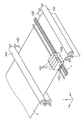
図1は本発明の代表的な実施例であるインクジェット記録装置(以下、記録装置という)の全体構成の概要を示す外観斜視図である。 FIG. 1 is an external perspective view showing an outline of the overall configuration of an ink jet recording apparatus (hereinafter referred to as a recording apparatus) which is a typical embodiment of the present invention.
図1に示されているように、x方向(主走査方向)に往復移動するキャリッジ106には4色のカラーインク、即ち、ブラック(K)、シアン(C)、マゼンタ(M)、イエロ(Y)インクがそれぞれ収容されたインクタンク101と記録ヘッド102とから構成されるインクカートリッジが搭載されている。
As shown in FIG. 1, the
記録を行うときには、搬送ローラ103と補助ローラ104とが記録媒体Pを挟持しながら図1に示された矢印の方向に回転し、記録ヘッド102による1走査分の記録が完了するたび毎に記録媒体Pをy方向(副走査方向)に搬送する。なお、記録の開始に当たっては、給紙ローラ105が記録媒体Pの給紙を行うとともに、搬送ローラ103と補助ローラ104と同様、記録媒体Pを抑える役割も果たす。
When recording is performed, the
記録を行っていないとき、あるいは記録ヘッド102の回復作業などを行うときには、キャリッジ106は図1中に点線で示した位置(ホームポジション(h))移動し、その場所で待機するようになっている。
When recording is not performed or when the recovery operation of the
図2は記録ヘッド102に配列されたインク吐出口の様子をz方向から示した図である。
FIG. 2 is a diagram showing the state of the ink discharge ports arranged in the
図2において、201は記録ヘッド102に複数配列された吐出口である。
In FIG. 2,
ここで、図1と図2とを参照してキャリッジ1走査分の記録動作を説明する。 Here, a recording operation for one scanning of the carriage will be described with reference to FIGS.
記録開始前、図1のホームポジションhにあるキャリッジ106は、ホスト(不図示)からの記録開始命令を記録装置が受信すると、x方向に移動しながら、さらに受信する記録データに従って記録ヘッド102の複数の吐出口201から記録媒体Pにインクを吐出して記録を行う。その後、記録媒体の端部(ホームポジションとは反対側)まで記録が終了するとキャリッジ106は元のホームポジションhに戻り、その復帰中に記録媒体Pをy方向に記録ヘッドによる1走査分の記録幅だけ搬送する。その後、再び、キャリッジ106をx方向に移動して記録を行う。
Prior to the start of recording, when the recording apparatus receives a recording start command from a host (not shown), the
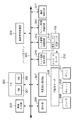
図3は図1に示す記録装置の制御構成を示すブロック図である。 FIG. 3 is a block diagram showing a control configuration of the recording apparatus shown in FIG.
図3に示されるように、記録装置の制御構成は、メインバスライン305に対して夫々アクセスする画像入力部303、それに対応する画像信号処理部304、CPU300といったデータ処理サブシステムと、操作部306、回復系制御回路307、ヘッド温度制御回路314、ヘッド駆動制御回路315、キャリッジ駆動制御回路316、搬送制御回路317といった機構制御処理サブシステムとに大別される。なお、画像入力部303はホストコンピュータ(不図示)からの記録データを入力するインタフェース、デジタルカメラ(不図示)からの画像データを入力するインタフェース、ICメモリカード(不図示)からの画像データを入力するインタフェースを備えている。
As shown in FIG. 3, the control configuration of the recording apparatus includes an
CPU300は、ROM301とRAM302などのメモリを備え、入力情報に対して適正な記録条件を与えて記録ヘッド102を駆動して記録を行う。また、RAM302には、予めヘッド回復タイミングチャートを実行するプログラムが格納されており、必要に応じて予備吐出条件等の回復条件を回復系制御回路307、ヘッド駆動制御回路315等に与える。
The
回復系モータ308は、記録ヘッド102とこれに対向離間するクリーニングブレード309、キャップ310、ポンプ311を駆動する。ヘッド駆動制御回路315は、記録ヘッド102に備えられた記録素子(電気熱変換体)の駆動条件を実行するもので、通常、インク予備吐出や記録用インク吐出を記録ヘッド102に行わせる。
The
図3に示されているように、記録ヘッド102の記録素子が設けられている基板には保温ヒータ313が設けられており、このヒータに通電することで記録ヘッド内のインク温度を所望設定温度に加熱調整することができる。又、ダイオードセンサ312は、同様に前記基板に設けられているもので、実質的な記録ヘッド内部のインク温度を測定する。なお、ダイオードセンサ312も保温ヒータ313と同様に基板に設けられていても良いが、基板外に設けられていても良く、或いは記録ヘッドの周囲近傍にあっても良い。
As shown in FIG. 3, a
次に、以上の装置構成において、いくつかの実施例について説明する。 Next, some examples of the above apparatus configuration will be described.
<第1の実施例>
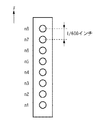
図4は第1実施例に従う記録ヘッド102のインク吐出口の配列を示す図である。このインク吐出口からは、上述のように、ブラック(K)、シアン(C)、マゼンタ(M)、イエロ(Y)インクのいずれかが吐出する。
<First embodiment>
FIG. 4 is a diagram showing an array of ink ejection openings of the
さて、図4に示した記録ヘッドは、副走査方向に1インチ当たりN=600個の密度で(600dpi)n=8個の吐出口(8ノズル)を有している。図4に示したn1からn8はノズル番号であり、各インク吐出口からのインク滴の大きさは約5plである。各インク吐出口の内部には、それぞれに対応した記録素子(電気熱変換体)が1個ずつ設けられている。 The recording head shown in FIG. 4 has N = 600 density per inch (600 dpi) and n = 8 ejection ports (8 nozzles) in the sub-scanning direction. In FIG. 4, n1 to n8 are nozzle numbers, and the size of ink droplets from each ink ejection port is about 5 pl. One recording element (electrothermal converter) corresponding to each ink discharge port is provided inside each ink discharge port.
図5は第1実施例における画像データの量子化レベル(階調レベル)と記録ドット数と画素データとの関係を説明する図である。 FIG. 5 is a diagram for explaining the relationship among the quantization level (gradation level) of image data, the number of recording dots, and pixel data in the first embodiment.
この実施例において、画像データは1画素当り600×600dpiの解像度の多値画像データであり、これが0から4までの5レベルに量子化されている。具体的には、量子化レベルに対応した4ビットのデータ(以下、画素データ)になっている。この量子化は多値画像データが画像入力部303に入力された後に画像信号処理部304で実行しても良いし、記録装置の負荷軽減のために入力画像データが既に量子化データとなっていても良い。
In this embodiment, the image data is multi-valued image data having a resolution of 600 × 600 dpi per pixel, and this is quantized to 5 levels from 0 to 4. Specifically, it is 4-bit data (hereinafter referred to as pixel data) corresponding to the quantization level. This quantization may be executed by the image
図5が示すように、量子化レベル0ではインク吐出はなく、即ち、1画素に対する記録ドット数は“0”で、4ビットの画素データは全ビットがOFFとなる「0000」の1種類となる。また、量子化レベル1では1回のインク吐出が発生し、1画素に対する記録ドット数は“1”で、4ビットの画素データはいずれかのビットがONとなる「0001、0010、0100、1000」の4種類となる。さらに、量子化レベル2では2回のインク吐出が発生し、1画素に対する記録ドット数は“2”で、4ビットの画素データはいずれか2つのビットがONとなる「0011、0101、0110、1001、1010、1100」の6種類となる。
As shown in FIG. 5, there is no ink ejection at
またさらに、量子化レベル3は3回のインク吐出が発生し、1画素に対する記録ドット数は“3”で、4ビットの画像データはいずれか3つのビットがONとなる「0111、1011、1101、1110」の4種類となり、最後に、量子化レベル4では4回のインク吐出が発生し、1画素に対する記録ドット数は“4”で、4ビットの画素データは全ビットONとなる「1111」の1種類となる。
Further, at the
この実施例では、このように量子化レベルに応じて記録する画素データを選択し、解像度600×600dpiの格子にインク液滴を吐出して記録する。なお、複数種類のビットパターンが存在する画素データに対応した量子化レベル(量子化レベル1、2、3)においては、複数種類のビットパターン中からランダムな選択を行う。
In this embodiment, pixel data to be recorded is selected according to the quantization level as described above, and ink droplets are ejected and recorded on a grid having a resolution of 600 × 600 dpi. Note that at the quantization level (
図6は第1実施例における第1の記録動作を説明する図である。 FIG. 6 is a diagram for explaining the first recording operation in the first embodiment.
図6では、記録ヘッドの全てのインク吐出口を用いて1回の走査で記録可能な領域(記録ヘッドの全ノズル幅に対応した記録領域)を、1画素4ビットの画像データに従い、4回の走査で記録する(マルチパス記録)様子を説明している。 In FIG. 6, an area (recording area corresponding to the entire nozzle width of the recording head) that can be recorded in one scan using all the ink discharge ports of the recording head is displayed four times according to image data of 4 bits per pixel. The state of recording (multi-pass recording) is described.
また、図7は図6に示した記録動作で記録する画素データに関し、解像度600×600dpiの1画素内でのドット配置(インク液滴付着位置)のパターンを説明する図である。 FIG. 7 is a diagram for explaining the pattern of dot arrangement (ink droplet adhesion position) in one pixel with a resolution of 600 × 600 dpi, regarding the pixel data recorded by the recording operation shown in FIG.
図7において、(a)は、4ビットの画素データで各ビットのデータを“a”から“d”で示しており、(b)は、600×600dpiの格子内を2×2の1200×1200dpiの格子に区切った左上の“a”の位置にドットを配置することを示し、(c)は、量子化レベルに応じて、“a”の位置に配置されるドットを示している。つまり、第1の記録動作では、各画素に対し、当該画素の量子化に対応した図7(c)のようなドット配置パターンが割当てられるのである。 In FIG. 7, (a) is 4-bit pixel data and each bit data is indicated by “a” to “d”, and (b) is 2 × 2 1200 × in a 600 × 600 dpi lattice. This indicates that a dot is arranged at the position of “a” in the upper left divided by a 1200 dpi lattice, and (c) shows the dot arranged at the position of “a” according to the quantization level. That is, in the first recording operation, a dot arrangement pattern as shown in FIG. 7C corresponding to the quantization of the pixel is assigned to each pixel.
ここで、図6に戻って説明を続けると、まず、1走査目の記録では、記録媒体を全ノズル幅の1/4に当たる2/600インチの搬送量で副走査方向に搬送した後、画像領域(1)には記録ヘッドの吐出口n7、n8を用いて、図7(a)の画素データの内、ビット位置“a”のデータのみを選択して記録を行う。詳しくは、記録ヘッドからの主走査方向における吐出タイミングは、600dpiの記録画素を主走査方向に1/2に分割した2倍の分解能で吐出可能なタイミングとなっており、この600dpiの記録画素を主走査方向に1/2に分割した前半の吐出タイミングのみインク吐出しながら主走査方向の往路方向に記録を行う。このようにして、各画素については図7(b)のaの位置に記録ドットが配置されて記録される。 Here, returning to FIG. 6, the description will be continued. First, in the first scan recording, the recording medium is transported in the sub-scanning direction by a transport amount of 2/600 inch corresponding to 1/4 of the entire nozzle width, and then the image is scanned. In the area (1), using the ejection ports n7 and n8 of the recording head, only the data of the bit position “a” is selected from the pixel data of FIG. Specifically, the ejection timing in the main scanning direction from the recording head is a timing at which the 600 dpi recording pixel can be ejected with a resolution that is halved in the main scanning direction. Printing is performed in the forward direction of the main scanning direction while discharging ink only in the first half of the discharge timing divided in half in the main scanning direction. In this way, for each pixel, a recording dot is arranged and recorded at the position a in FIG. 7B.
次に、2走査目では、2/600インチの搬送量で記録媒体Pを副走査方向に搬送した後、画像領域(1)には吐出口n5、n6を用い、画像領域(2)には吐出口n7、n8を用いて、図7(a)の画素データの内、ビット位置“b”のデータのみを選択して記録を行う。詳しくは、600dpiの記録画素を主走査方向に1/2に分割した前半の吐出タイミングのみで1走査目と同じ格子点にインクを吐出しながら主走査方向の往路方向に記録を行う。このようにして、各画素については図7(b)のaの位置に記録ドットが配置されて記録される。 Next, in the second scan, after the recording medium P is transported in the sub-scanning direction by a transport amount of 2/600 inch, the ejection openings n5 and n6 are used for the image area (1), and the image area (2) Using the discharge ports n7 and n8, only the data at the bit position “b” is selected from the pixel data in FIG. Specifically, recording is performed in the forward direction of the main scanning direction while ejecting ink to the same grid point as that of the first scanning only at the first half of the ejection timing when the 600 dpi recording pixel is divided in half in the main scanning direction. In this way, for each pixel, a recording dot is arranged and recorded at the position a in FIG. 7B.
さらに、3走査目では、2/600インチの搬送量で記録媒体Pを副走査方向に搬送した後、画像領域(1)には吐出口n3、n4を用い、画像領域(2)には吐出口n5、n6を用い、画像領域(3)には吐出口n7、n8を用いて、図7(a)の画素データの内、ビット位置“c”のデータのみを選択して記録を行う。詳しくは、600dpiの記録画素を主走査方向に1/2に分割した前半の吐出タイミングのみで、1、2走査目と同じ格子点にインクを吐出しながら主走査方向の往路方向に記録を行う。このようにして、各画素については図7(b)のaの位置に記録ドットが配置されて記録される。 Further, in the third scan, after the recording medium P is transported in the sub-scanning direction by a transport amount of 2/600 inch, the ejection openings n3 and n4 are used for the image area (1) and the ejection is performed for the image area (2). Using the outlets n5 and n6 and the ejection openings n7 and n8 in the image area (3), only the data at the bit position “c” is selected from the pixel data in FIG. Specifically, printing is performed in the forward direction of the main scanning direction while ejecting ink to the same grid points as in the first and second scans only at the first half of the ejection timing when the 600 dpi recording pixel is divided in half in the main scanning direction. . In this way, for each pixel, a recording dot is arranged and recorded at the position a in FIG. 7B.
さらにまた、4走査目では、2/600インチの搬送量で記録媒体Pを副走査方向に搬送した後、画像領域(1)には吐出口n1、n2を用い、画像領域(2)には吐出口n3、n4を用い、画像領域(3)には吐出口n5、n6を用い、画像領域(4)には吐出口n7、n8を用いて、図7(a)の画素データの内、ビット位置“d”のデータのみを選択して記録を行う。詳しくは、600dpiの記録画素を主走査方向に1/2に分割した前半の吐出タイミングのみで1〜3走査目と同じ格子点にインクを吐出しながら主走査方向の往路方向に記録を行う。このようにして、各画素については図7(b)のaの位置に記録ドットが配置されて記録される。 Furthermore, in the fourth scan, after the recording medium P is transported in the sub-scanning direction by a transport amount of 2/600 inch, the ejection openings n1 and n2 are used for the image area (1), and the image area (2) Among the pixel data in FIG. 7A, the discharge ports n3 and n4 are used, the discharge ports n5 and n6 are used for the image region (3), and the discharge ports n7 and n8 are used for the image region (4). Only data at bit position “d” is selected for recording. Specifically, printing is performed in the forward direction of the main scanning direction while ejecting ink to the same grid points as in the first to third scans only at the first half of the ejection timing when the 600 dpi recording pixel is divided in half in the main scanning direction. In this way, for each pixel, a recording dot is arranged and recorded at the position a in FIG. 7B.
5走査目以降も、1から4走査目と同様の方法で記録を行う。 In the fifth and subsequent scans, recording is performed in the same manner as in the first to fourth scans.
図8は第1の記録動作によって記録された各量子化レベルに対応した2×2の画素へのドット分布を示した図である。 FIG. 8 is a diagram showing a dot distribution to 2 × 2 pixels corresponding to each quantization level recorded by the first recording operation.
図8において、(a)が量子化レベル1、(b)が量子化レベル2、(c)が量子化レベル3、(d)が量子化レベル4を示し、これらの図からどのレベルにおいても均等間隔でドットが配置されていることが分かる。
In FIG. 8, (a) shows the
図9は第1実施例における第2の記録動作を説明する図である。 FIG. 9 is a diagram for explaining a second recording operation in the first embodiment.
図9でも、第1の記録動作と同様、記録ヘッドの全てのインク吐出口を用いて1回の走査で記録可能な領域を、1画素4ビットの画像データに従い、4回の走査で記録する(マルチパス記録)様子を説明している。 In FIG. 9 as well, as in the first recording operation, an area that can be recorded by one scan using all the ink ejection ports of the recording head is recorded by four scans according to image data of 4 bits per pixel. (Multi-pass recording) is described.
また、図10は図7に示した記録動作で記録する画素データに関し、解像度600×600dpiの1画素内でのドット配置(インク液滴付着位置)パターンを説明する図である。 FIG. 10 is a diagram for explaining a dot arrangement (ink droplet adhesion position) pattern in one pixel having a resolution of 600 × 600 dpi with respect to pixel data recorded by the recording operation shown in FIG.
図10において、(a)は、4ビットの画素データで各ビットのデータを“a”から“d”で示しており、(b)は、600×600dpiの格子内を2×2の1200×1200dpiの格子に区切った左上の“a”と左下の“b”の位置にドットを配置することを示し、(c)は、量子化レベルに応じて、“a”と“b”の位置に配置されるドットを示している。つまり、第2の記録動作では、各画素に対し、当該画素の量子化に対応した図10(c)のようなドット配置パターンが割当てられるのである。 In FIG. 10, (a) is 4-bit pixel data and each bit data is indicated by “a” to “d”, and (b) is 2 × 2 1200 × in a 600 × 600 dpi lattice. This indicates that dots are arranged at the positions of “a” at the upper left and “b” at the lower left divided by a 1200 dpi grid, and (c) shows the positions at “a” and “b” according to the quantization level. The dots to be arranged are shown. That is, in the second recording operation, a dot arrangement pattern as shown in FIG. 10C corresponding to the quantization of the pixel is assigned to each pixel.
さらに、図10(c)に示すように、量子化レベル1では2種類、量子化レベル2では3種類、量子化レベル3では4種類、量子化レベル4では5種類のドット配置(インク液滴付着位置)パターンが存在する。
Furthermore, as shown in FIG. 10 (c), two types of dot arrangements (ink droplets) at
ここで、図9に戻って説明を続けると、まず、1走査目の記録では、記録媒体を記録ヘッドの全ノズル幅の約1/4に当たる2.5/600(=5/1200)インチの搬送量で副走査方向に搬送した後、画像領域(1)には記録ヘッドの吐出口n7、n8を用いて、図10(a)の画素データの内、ビット位置“a”のデータのみを選択して記録を行う。詳しくは、600dpiの記録画素を主走査方向に1/2に分割した前半の吐出タイミングのみでインク吐出しながら主走査方向の往路方向に記録を行う。このようにして、各画素については図10(b)のbの位置に記録ドットが配置されて記録される。 Here, returning to FIG. 9, the description will be continued. First, in the first-scan recording, the recording medium is 2.5 / 600 (= 5/1200) inches, which is about 1/4 of the total nozzle width of the recording head. After transporting in the sub-scanning direction by the transport amount, only the data at the bit position “a” in the pixel data of FIG. 10A is used for the image area (1) by using the ejection openings n7 and n8 of the recording head. Select and record. Specifically, printing is performed in the forward direction of the main scanning direction while ejecting ink only at the first half of the ejection timing obtained by dividing a 600 dpi recording pixel in half in the main scanning direction. In this way, for each pixel, a recording dot is arranged and recorded at a position b in FIG.
次に、2走査目では、1.5/600(=3/1200)インチの搬送量で記録媒体Pを副走査方向に搬送した後、画像領域(1)には吐出口n5、n6を用い、画像領域(2)には吐出口n7、n8を用いて、図10(a)の画素データの内、ビット位置“b”のデータのみを選択して記録を行う。詳しくは、600dpiの記録画素を主走査方向に1/2に分割した前半の吐出タイミングのみで1走査目のドット記録位置とは副走査方向に1/1200インチだけずれた位置にインクを吐出しながら主走査方向の往路方向に記録を行う。このようにして、各画素については図10(b)のaの位置に記録ドットが配置されて記録される。 Next, in the second scan, after the recording medium P is transported in the sub-scanning direction by a transport amount of 1.5 / 600 (= 3/1200) inches, the ejection openings n5 and n6 are used for the image area (1). In the image area (2), by using the ejection ports n7 and n8, only the data at the bit position “b” is selected from the pixel data in FIG. Specifically, ink is ejected to a position shifted by 1/1200 inch in the sub-scanning direction from the dot scanning position in the first scanning only at the ejection timing of the first half when the 600 dpi recording pixel is divided in half in the main scanning direction. However, recording is performed in the forward direction of the main scanning direction. In this way, for each pixel, a recording dot is arranged and recorded at the position a in FIG.
さらに、3走査目では、2.5/600(=5/1200)インチの搬送量で記録媒体Pを副走査方向に搬送した後、画像領域(1)には吐出口n3、n4を用い、画像領域(2)には吐出口n5、n6を用い、画像領域(3)には吐出口n7、n8を用いて、図10(a)の画素データの内、ビット位置“c”のデータのみを選択して記録を行う。詳しくは、600dpiの記録画素を主走査方向に1/2に分割した前半の吐出タイミングのみで、1走査目と同じ格子点にインクを吐出しながら主走査方向の往路方向に記録を行う。このようにして、各画素については図10(b)のbの位置に記録ドットが配置されて記録される。 Further, in the third scan, after the recording medium P is transported in the sub-scanning direction by a transport amount of 2.5 / 600 (= 5/1200) inches, the ejection openings n3 and n4 are used for the image area (1). Using the ejection openings n5 and n6 for the image area (2) and the ejection openings n7 and n8 for the image area (3), only the data at the bit position “c” in the pixel data of FIG. Select to record. Specifically, printing is performed in the forward direction of the main scanning direction while ejecting ink to the same grid point as that of the first scanning only at the first half of the ejection timing when the 600 dpi recording pixel is divided in half in the main scanning direction. In this way, for each pixel, a recording dot is arranged and recorded at a position b in FIG.
さらにまた、4走査目では、1.5/600(=3/1200)インチの搬送量で記録媒体Pを副走査方向に搬送した後、画像領域(1)には吐出口n1、n2を用い、画像領域(2)には吐出口n3、n4を用い、画像領域(3)には吐出口n5、n6を用い、画像領域(4)には吐出口n7、n8を用いて、図10(a)の画素データの内、ビット位置“d”のデータのみを選択して記録を行う。詳しくは、600dpiの記録画素を主走査方向に1/2に分割した前半の吐出タイミングのみで2走査目と同じ格子点にインクを吐出しながら主走査方向の往路方向に記録を行う。このようにして、各画素については図10(b)のaの位置に記録ドットが配置されて記録される。 Furthermore, in the fourth scan, after the recording medium P is transported in the sub-scanning direction by a transport amount of 1.5 / 600 (= 3/1200) inches, the ejection ports n1 and n2 are used for the image area (1). The discharge ports n3 and n4 are used for the image region (2), the discharge ports n5 and n6 are used for the image region (3), and the discharge ports n7 and n8 are used for the image region (4). Of the pixel data of a), only the data at bit position “d” is selected for recording. Specifically, printing is performed in the forward direction of the main scanning direction while ejecting ink to the same grid point as that of the second scanning only at the first half of the ejection timing when the 600 dpi recording pixel is divided in half in the main scanning direction. In this way, for each pixel, a recording dot is arranged and recorded at the position a in FIG.
5走査目以降も、1から4走査目と同様の方法で記録を行う。 In the fifth and subsequent scans, recording is performed in the same manner as in the first to fourth scans.
図11は第2の記録動作によって記録された各量子化レベルに対応した2×2の画素へのドット分布を示した図である。 FIG. 11 is a diagram showing a dot distribution to 2 × 2 pixels corresponding to each quantization level recorded by the second recording operation.
図11において、(a)が量子化レベル1、(b)が量子化レベル2、(c)が量子化レベル3、(d)が量子化レベル4を示し、これらの図から各レベルにおいて、ドット配置は不均一になっていることが分かる。図11に示す600×600dpiでの2×2の画素マトリクスにおいて、左上と右下の画素が全て、図10(b)のaの位置に記録されるドット配置であり、右上と左下の画素が全て、図10(b)のbの位置に記録されるドット配置である。
In FIG. 11, (a) shows the
次に、第1の記録動作と第2の記録動作によって得られた記録画像の品質について検討する。 Next, the quality of the recorded image obtained by the first recording operation and the second recording operation will be examined.
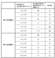
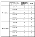
図12は第1の記録動作と第2の記録動作によって記録される記録媒体の主走査方向のサイズと主走査及び副走査方向に関する濃度ムラと粒状感との関係を示す図である。 FIG. 12 is a diagram showing the relationship between the size in the main scanning direction of the recording medium recorded by the first recording operation and the second recording operation, density unevenness in the main scanning and sub-scanning directions, and graininess.
図12において、記録画像の品質は5段階評価しており、◎は非常に良好、○は良好、△は普通、×は悪い、××は非常に悪いを表わす。 In FIG. 12, the quality of the recorded image is evaluated on a five-point scale, where ◎ is very good, ○ is good, Δ is normal, × is bad, and XX is very bad.
まず、前提として、第1の記録動作の場合も第2の記録動作の場合も、濃度ムラに関しては記録媒体のサイズが小さいほど良好であり、また、粒状感に関しては記録媒体のサイズが大きいほど良好である。ここで、記録媒体のサイズが小さいほど濃度ムラが目立たないのは、記録媒体のサイズが小さい程、視覚的に濃度ムラの発生周期が相対的に大きくなり、濃度ムラの粗密の数が減少するためである。一方、記録媒体のサイズが大きいほど粒状感が低減するのは、記録媒体との目視距離が離れることで視覚的に空間周波数が高くなるためである。 First, as a premise, in both the first recording operation and the second recording operation, the smaller the recording medium size, the better the density unevenness, and the larger the recording medium size in terms of graininess. It is good. Here, the density unevenness is less noticeable as the size of the recording medium is smaller. The smaller the size of the recording medium, the larger the generation period of density unevenness is visually and the number of density unevenness decreases. Because. On the other hand, the graininess decreases as the size of the recording medium increases because the spatial frequency increases visually as the viewing distance from the recording medium increases.
次に、第1の記録動作について検討する。この第1の記録動作では、主走査及び副走査方向への濃度ムラに関しては、記録媒体の主走査方向のサイズが4インチ以下では良好なレベルだが、そのサイズが4インチより大きくなると良好ではなくなり、濃度ムラが目立ってくる。すなわち、第1の記録動作では、各量子化レベルに対応するドット配置パターンとして1種類のドット配置パターン(図7(c)参照)しか使用していないため、生来的に、周期的な濃度ムラが目立たちやすい構成となっており、とりわけ、濃度ムラが目立ちやすい大きなサイズの記録媒体の場合には、濃度ムラのレベルが許容できなくなってしまう。一方、粒状感に関しては、記録媒体の主走査方向のサイズが大きくなるに伴って良好になってはいくものの、記録媒体のサイズが小さい場合であっても、十分良好である。すなわち、第1の記録動作では、図7(c)のドット配置パターンを使用することにより、図8に示す様にどの量子化レベルにおいても均等間隔で記録ドットが配置されるため、全体的に粒状感は目立ちにくい傾向がある。なお、記録媒体の主走査方向のサイズが大きくなるにつれて記録媒体との目視距離が離れるため、記録媒体の主走査方向のサイズが大きい程、粒状感は低減されるのであるが、粒状感が比較的目立ちやすい4インチ以下の小さなサイズであっても、この第1の記録動作の場合、粒状感は良好である。以上の事項を鑑みれば、比較的大きなサイズの記録媒体の場合に第1の記録動作を用いてしまうと、粒状感の点では良好であるが、濃度ムラの点で問題が生じてしまう。一方、比較的小さなサイズの記録媒体の場合に第1の記録動作を用いると、濃度ムラおよび粒状感が抑制された画像を記録することができる。 Next, the first recording operation will be considered. In the first recording operation, the density unevenness in the main scanning and sub-scanning directions is good when the size of the recording medium in the main scanning direction is 4 inches or less, but is not good when the size is larger than 4 inches. , Density unevenness becomes conspicuous. That is, in the first recording operation, only one type of dot arrangement pattern (see FIG. 7C) is used as a dot arrangement pattern corresponding to each quantization level, so that the periodic density unevenness naturally occurs. In particular, in the case of a large-sized recording medium in which density unevenness is conspicuous, the level of density unevenness becomes unacceptable. On the other hand, the graininess is improved as the size of the recording medium in the main scanning direction increases, but is sufficiently good even when the size of the recording medium is small. That is, in the first recording operation, by using the dot arrangement pattern of FIG. 7C, the recording dots are arranged at equal intervals at any quantization level as shown in FIG. The graininess tends to be inconspicuous. As the size of the recording medium in the main scanning direction increases, the visual distance from the recording medium increases. Therefore, the larger the size of the recording medium in the main scanning direction, the more the graininess is reduced. Even in a small size of 4 inches or less that is easily noticeable, the graininess is good in the first recording operation. In view of the above matters, if the first recording operation is used in the case of a recording medium of a relatively large size, although it is good in terms of graininess, a problem occurs in terms of density unevenness. On the other hand, when the first recording operation is used in the case of a recording medium having a relatively small size, an image in which density unevenness and graininess are suppressed can be recorded.
一方、第2の記録動作では、主走査及び副走査方向への濃度ムラに関しては、記録媒体の主走査方向のサイズがどんなサイズであっても良好なレベルである。すなわち、第2の記録動作では、各量子化レベルに対応するドット配置パターンとして複数種類のドット配置パターン(図10(c)参照)を使用しており、元々ノイズ感が加わっているため、生来的に、周期的な濃度ムラが目立たちにくい構成となっており、濃度ムラが比較的目立ちやすい大きなサイズの記録媒体の場合であっても、濃度ムラは十分低減されており、濃度ムラレベルとしては十分良好である。一方、粒状感に関しては、図11に示す様にどの量子化レベルにおいても不均等な間隔で記録ドットが配置されるため、言い換えれば、元々ノイズ感が加わっているため、粒状感は第1の記録動作よりも、やや悪い傾向にある。特に、記録媒体の主走査方向のサイズが小さくなるにつれて記録媒体との目視距離が近づくため、記録媒体のサイズが小さい程、粒状感が悪化してしまう。 On the other hand, in the second recording operation, the density unevenness in the main scanning and sub-scanning directions is at a satisfactory level regardless of the size of the recording medium in the main scanning direction. That is, in the second recording operation, a plurality of types of dot arrangement patterns (see FIG. 10C) are used as the dot arrangement patterns corresponding to the respective quantization levels. In particular, the periodic density unevenness is not conspicuous, and the density unevenness is sufficiently reduced even in the case of a large-sized recording medium in which the density unevenness is relatively conspicuous. Good enough. On the other hand, with respect to the graininess, since the recording dots are arranged at unequal intervals at any quantization level as shown in FIG. 11, in other words, since the noise feeling is originally added, the graininess is the first. It tends to be slightly worse than the recording operation. In particular, as the size of the recording medium in the main scanning direction becomes smaller, the visual distance from the recording medium becomes closer, so that the graininess deteriorates as the size of the recording medium becomes smaller.
図12によれば、4インチ以下の小さなサイズの記録媒体の場合には、粒状感のレベルは良好ではなくなってしまう。以上の事項を鑑みれば、比較的小さなサイズの記録媒体の場合に第2の記録動作を用いてしまうと、濃度ムラの点では良好であるが、粒状感の点で問題が生じてしまう。一方、比較的大きなサイズの記録媒体の場合に第2の記録動作を用いると、濃度ムラおよび粒状感が抑制された画像を記録することができる。 According to FIG. 12, in the case of a recording medium having a small size of 4 inches or less, the level of graininess is not good. In view of the above matters, if the second recording operation is used in the case of a recording medium having a relatively small size, although it is good in terms of density unevenness, a problem arises in terms of graininess. On the other hand, when the second recording operation is used in the case of a relatively large recording medium, an image in which density unevenness and graininess are suppressed can be recorded.
以上の検討をまとめると、比較的小さなサイズの記録媒体の場合、第2の記録動作を用いてしまうと、濃度ムラの点では良好であるものの、粒状感の点で問題が生じてしまうため、濃度ムラと粒状感の両方を低減させることはできない一方、第1の記録動作を用いると、濃度ムラと粒状感の両方を低減させることができる。従って、比較的小さなサイズの記録媒体の場合には、各量子化レベルに対応したドット配置パターンとして、図7(c)のような1種類のドット配置パターンを使用して記録を行う第1の記録動作を用いることが好ましい。また、比較的大きなサイズの記録媒体の場合、第1の記録動作を用いてしまうと、粒状感の点では良好であるものの、濃度ムラの点で問題が生じてしまうため、濃度ムラと粒状感の両方を低減させることはできない一方、第2の記録動作を用いると、濃度ムラと粒状感の両方を低減させることができる。従って、比較的大きなサイズの記録媒体の場合には、各量子化レベルに対応したドット配置パターンとして、図10(c)のような複数種類のドット配置パターンを使用して記録を行う第2の記録動作を用いることが好ましい。 To summarize the above consideration, in the case of a relatively small size recording medium, if the second recording operation is used, although it is good in terms of density unevenness, a problem occurs in terms of graininess. While both density unevenness and graininess cannot be reduced, using the first recording operation can reduce both density unevenness and graininess. Accordingly, in the case of a recording medium having a relatively small size, the first recording is performed by using one kind of dot arrangement pattern as shown in FIG. 7C as the dot arrangement pattern corresponding to each quantization level. It is preferable to use a recording operation. Further, in the case of a relatively large size recording medium, if the first recording operation is used, although it is good in terms of graininess, a problem arises in terms of density unevenness. Both cannot be reduced, but if the second recording operation is used, both density unevenness and graininess can be reduced. Therefore, in the case of a relatively large recording medium, the second recording is performed using a plurality of types of dot arrangement patterns as shown in FIG. 10C as the dot arrangement patterns corresponding to the respective quantization levels. It is preferable to use a recording operation.
従って、以上のような検討結果より、記録に用いる記録媒体のサイズが4インチ以下の場合は、第1の記録動作を実行する一方、その記録に用いる記録媒体のサイズが4インチより大きい場合は、第2の記録動作を実行することで、主走査及び副走査方向への濃度ムラと粒状感の両方を許容できるレベルに抑えられることが分かる。つまり、記録媒体のサイズに対応した異なるドット配置パターンを各画素に割当てるに際し、記録媒体のサイズが比較的小さい場合には、量子化レベルが同じ複数の画素に対し1種類のドット配置パターン(図7(c)のようなパターン)を割当て、一方、記録媒体のサイズが比較的大きい場合、量子化レベルが同じ複数の画素に対して複数の異なるドット配置パターン(図10(c)のようなパターン))を割当てることで、記録媒体のサイズによらず濃度ムラ抑制効果と粒状感抑制効果の両立が可能となるのである。。 Accordingly, from the above examination results, when the size of the recording medium used for recording is 4 inches or less, the first recording operation is executed, while when the size of the recording medium used for recording is larger than 4 inches. It can be seen that by executing the second recording operation, both density unevenness and graininess in the main scanning and sub-scanning directions can be suppressed to an acceptable level. That is, when assigning different dot arrangement patterns corresponding to the size of the recording medium to each pixel, if the size of the recording medium is relatively small, one kind of dot arrangement pattern (see FIG. 7 (c)), while the size of the recording medium is relatively large, a plurality of different dot arrangement patterns (as shown in FIG. 10 (c)) for a plurality of pixels having the same quantization level. By assigning the pattern)), it is possible to achieve both the density unevenness suppressing effect and the graininess suppressing effect regardless of the size of the recording medium. .
従って以上のような検討を踏まえ、以下に示すような記録制御を実行する。 Therefore, based on the above examination, the following recording control is executed.
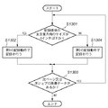
図13はこの実施例に従う記録制御を示すフローチャートである。 FIG. 13 is a flowchart showing the recording control according to this embodiment.
まず、ステップS1301では、画像入力部303に入力される画像データに付加されている記録に必要な記録媒体のサイズに関する情報に基づいて、記録媒体の主走査方向のサイズが4インチ以下かどうかを調べる。
First, in step S1301, whether or not the size of the recording medium in the main scanning direction is 4 inches or less is determined based on information about the size of the recording medium necessary for recording added to the image data input to the
ここで、その記録媒体の主走査方向のサイズが4インチ以下であると判断されれば、処理はステップS1302に進み、第1の記録動作で記録を行い、その後、処理はステップS1303に進む。これに対して、そのサイズが4インチより大きいと判断されれば、処理はステップS1304に進み、第2の記録動作で記録を行う。その後、処理はステップS1303に進む。 If it is determined that the size of the recording medium in the main scanning direction is 4 inches or less, the process proceeds to step S1302, recording is performed in the first recording operation, and then the process proceeds to step S1303. On the other hand, if it is determined that the size is larger than 4 inches, the process proceeds to step S1304, and recording is performed by the second recording operation. Thereafter, processing proceeds to step S1303.
ステップS1303では、次ページ又は次ジョブの画像データがあるかどうかを調べ、さらに画像データがあると判断された場合には、処理はステップS1301に戻って前述の処理を繰返すが、画像データがない場合と判断された場合には、処理は終了する。 In step S1303, it is checked whether there is image data for the next page or the next job. If it is determined that there is more image data, the process returns to step S1301 and the above-described processing is repeated, but there is no image data. If it is determined to be a case, the process ends.
従って以上説明した実施例に従えば、記録媒体の主走査方向のサイズに応じて、記録媒体上の各記録画素内のドット配置であるインク液滴の付着位置を異ならせることで、濃度ムラを十分抑制し、かつ視覚的に粒状感を低減させた高品位な画像を記録することが可能になる。 Therefore, according to the embodiment described above, the density unevenness can be reduced by changing the adhesion position of the ink droplets that are the dot arrangement in each recording pixel on the recording medium according to the size of the recording medium in the main scanning direction. It is possible to record a high-quality image that is sufficiently suppressed and visually reduced in graininess.
[変形例1]
さて、上述した第2の記録動作では、第1の記録動作と比較して副走査方向への記録媒体の搬送量を各走査記録毎に異ならせていたが、本発明はこれによって限定されるものではなく、例えば、第2の記録動作でも記録媒体の搬送量は第1の記録動作と同じにし、その代わり記録ヘッドを走査する主走査方向に関し、記録ヘッドからのインク液滴の吐出タイミングを異ならせても良い。
[Modification 1]
In the second recording operation described above, the conveyance amount of the recording medium in the sub-scanning direction is different for each scanning recording as compared with the first recording operation, but the present invention is limited thereto. For example, in the second recording operation, the transport amount of the recording medium is the same as that in the first recording operation. Instead, the ejection timing of the ink droplets from the recording head is set in the main scanning direction in which the recording head is scanned. It may be different.
図14は、図5で説明した画素データを第1の記録動作における搬送量と同じ搬送量とし、主走査方向への記録ヘッドからのインク液滴の吐出タイミングを異ならせて記録を行った場合の記録媒体上における各記録画素内の記録ドットの配置(インク液滴付着位置)パターンを説明する図である。 FIG. 14 shows a case where the pixel data described in FIG. 5 is set to the same transport amount as the transport amount in the first recording operation, and recording is performed with different ink droplet ejection timings in the main scanning direction. It is a figure explaining the arrangement | positioning (ink droplet adhesion position) pattern of the recording dot in each recording pixel on this recording medium.
図14において、(a)は、4ビットの画素データで各ビットのデータを“a”から“d”で示しており、(b)は、600×600dpiの格子内を2×2の1200×1200dpiの格子に区切った左上の“a”と右上の“b”の位置にドットを配置することを示し、(c)は、量子化レベルに応じて、“a”と“b”の位置に配置されるドットを示している。つまり、変形例1の記録動作では、各画素に対し、当該画素の量子化に対応した図14(c)のようなドット配置パターンが割当てられるのである。
In FIG. 14, (a) is 4-bit pixel data, and each bit data is indicated by “a” to “d”, and (b) is 2 × 2 1200 × in a 600 × 600 dpi lattice. This indicates that dots are arranged at the positions of “a” in the upper left and “b” in the upper right divided by a 1200 dpi grid, and (c) shows the positions at “a” and “b” according to the quantization level. The dots to be arranged are shown. That is, in the recording operation of
さらに、図14(c)に示すように、量子化レベル1は2種類、量子化レベル2は3種類、量子化レベル3は4種類、量子化レベル4は5種類のドット配置(インク液滴付着位置)パターンが存在する。
Further, as shown in FIG. 14 (c), two types of dot arrangements (ink droplets) include two types of
ここで、再び図6を参照して説明すると、まず、1走査目の記録では、記録媒体を全ノズル幅の1/4に当たる2/600インチの搬送量で副走査方向に搬送した後、画像領域(1)には記録ヘッドの吐出口n7、n8を用いて、図14(a)の画素データの内、ビット位置“a”のデータのみを選択して、記録を行う。詳しくは、記録ヘッドからの主走査方向での吐出タイミングは、600dpiの記録画素を主走査方向に1/2に分割した2倍の分解能で吐出可能なタイミングとなっており、この600dpiの記録画素を主走査方向に1/2に分割した前半の吐出タイミングのみでインク吐出しながら主走査方向の往路方向に記録を行う。このようにして、各画素については図14(b)のaの位置に記録ドットが配置されて記録される。 Here, referring to FIG. 6 again, in the first scan recording, after the recording medium is transported in the sub-scanning direction by a transport amount of 2/600 inch corresponding to 1/4 of the entire nozzle width, the image is scanned. In the area (1), using the ejection ports n7 and n8 of the recording head, only the data at the bit position “a” is selected from the pixel data in FIG. More specifically, the ejection timing from the recording head in the main scanning direction is a timing at which 600 dpi recording pixels can be ejected at a resolution of 2 by dividing the recording pixels by half in the main scanning direction. Is printed in the forward direction of the main scanning direction while ejecting ink only at the first half of the ejection timing divided in half in the main scanning direction. In this way, for each pixel, a recording dot is arranged and recorded at the position a in FIG.
次に、2走査目では、2/600インチの搬送量で記録媒体Pを副走査方向に搬送した後、画像領域(1)には吐出口n5、n6を用い、画像領域(2)には吐出口n7、n8を用いて、図14(a)の画素データの内、ビット位置“b”のデータのみを選択して記録を行う。詳しくは、600dpiの記録画素を主走査方向に1/2に分割した後半の吐出タイミングのみで1走査目のドット記録位置とは異なる吐出タイミングで主走査方向に1/1200インチだけずれた位置にインクを吐出しながら主走査方向の往路方向に記録を行う。このようにして、各画素については図14(b)のbの位置に記録ドットが配置されて記録される。 Next, in the second scan, after the recording medium P is transported in the sub-scanning direction by a transport amount of 2/600 inch, the ejection openings n5 and n6 are used for the image area (1), and the image area (2) Using the discharge ports n7 and n8, only the data at the bit position “b” is selected from the pixel data in FIG. Specifically, the position is shifted by 1/1200 inch in the main scanning direction at an ejection timing different from the dot recording position of the first scanning only by the second half ejection timing obtained by dividing the 600 dpi recording pixel by half in the main scanning direction. Recording is performed in the forward direction of the main scanning direction while ejecting ink. In this way, for each pixel, a recording dot is arranged and recorded at the position b in FIG.
さらに、3走査目では、2/600インチの搬送量で記録媒体Pを副走査方向に搬送した後、画像領域(1)には吐出口n3、n4を用い、画像領域(2)には吐出口n5、n6を用い、画像領域(3)には吐出口n7、n8を用いて、図14(a)の画素データの内、ビット位置“c”のデータのみを選択して記録を行う。詳しくは、600dpiの記録画素を主走査方向に1/2に分割した前半の吐出タイミングのみで、1走査目と同じ格子点にインクを吐出するタイミングで主走査方向の往路方向に記録を行う。このようにして、各画素については図14(b)のaの位置に記録ドットが配置されて記録される。 Further, in the third scan, after the recording medium P is transported in the sub-scanning direction by a transport amount of 2/600 inch, the ejection openings n3 and n4 are used for the image area (1) and the ejection is performed for the image area (2). Using the outlets n5 and n6 and the ejection openings n7 and n8 for the image area (3), only the data at the bit position “c” is selected from the pixel data in FIG. Specifically, printing is performed in the forward direction of the main scanning direction at the timing of ejecting ink to the same grid point as that of the first scanning only by the first half of the ejection timing obtained by dividing the 600 dpi recording pixel in half in the main scanning direction. In this way, for each pixel, a recording dot is arranged and recorded at the position a in FIG.
さらにまた、4走査目では、2/600インチの搬送量で記録媒体Pを副走査方向に搬送した後、画像領域(1)には吐出口n1、n2を用い、画像領域(2)には吐出口n3、n4を用い、画像領域(3)には吐出口n5、n6を用い、画像領域(4)には吐出口n7、n8を用いて、図14(a)の画素データの内、ビット位置“d”のデータのみを選択して記録を行う。詳しくは、600dpiの記録画素を主走査方向に1/2に分割した後半の吐出タイミングのみで2走査目と同じタイミングでインクを吐出しながら主走査方向の往路方向に記録を行う。このようにして、各画素については図14(b)のbの位置に記録ドットが配置されて記録される。 Furthermore, in the fourth scan, after the recording medium P is transported in the sub-scanning direction by a transport amount of 2/600 inch, the ejection openings n1 and n2 are used for the image area (1), and the image area (2) Among the pixel data in FIG. 14A, the discharge ports n3 and n4 are used, the discharge ports n5 and n6 are used for the image region (3), and the discharge ports n7 and n8 are used for the image region (4). Only data at bit position “d” is selected for recording. Specifically, printing is performed in the forward direction of the main scanning direction while ejecting ink at the same timing as the second scanning only with the second half of the ejection timing obtained by dividing the 600 dpi recording pixel in half in the main scanning direction. In this way, for each pixel, a recording dot is arranged and recorded at the position b in FIG.
5走査目以降も、1から4走査目と同様の方法で記録を行う。 In the fifth and subsequent scans, recording is performed in the same manner as in the first to fourth scans.
図15は変形例1に従って記録される各量子化レベルに対応した2×2の画素へのドット分布を示した図である。 FIG. 15 is a diagram showing a dot distribution to 2 × 2 pixels corresponding to each quantization level recorded according to the first modification.
図15において、(a)が量子化レベル1、(b)が量子化レベル2、(c)が量子化レベル3、(d)が量子化レベル4を示し、これらの図から各レベルにおいて、ドット配置は不均一になっていることが分かる。図15に示す600×600dpiでの2×2の画素マトリクスにおいて、左上と右下の画素が全て、図14(b)のaの位置に記録されるドット配置であり、右上と左下の画素が全て、図14(b)のbの位置に記録されるドット配置である。
In FIG. 15, (a) shows the
図15と図11とを比較してみると、図11の場合には記録ドットが副走査方向に不均等な間隔で配置されていたのに対して、図15は主走査方向に不均等な間隔で配置されていることがわかる。 Comparing FIG. 15 and FIG. 11, in the case of FIG. 11, the recording dots are arranged at unequal intervals in the sub-scanning direction, whereas FIG. 15 is unequal in the main scanning direction. It can be seen that they are arranged at intervals.
この様に、記録媒体の主走査方向のサイズに応じて記録媒体の搬送量を異ならせていたのと同様に、記録媒体の主走査方向のサイズに応じて、主走査方向に関し記録ヘッドからのインク液滴の吐出タイミングを異ならせても同様の効果を得ることができる。 As described above, the conveyance amount of the recording medium varies according to the size of the recording medium in the main scanning direction. Similarly, the main scanning direction from the recording head depends on the size of the recording medium in the main scanning direction. The same effect can be obtained even if the ejection timing of the ink droplets is varied.
[変形例2]
また、この実施例では記録媒体の主走査方向のサイズに応じて各記録画素内の記録ドット配置(インク液滴の付着位置)を異ならせていたが、本発明はこれによって限定されるものではない。例えば、記録媒体の副走査方向のサイズに応じて各記録画素内の記録ドット配置(インク液滴の付着位置)を異ならせても良いし、記録媒体の主走査方向のサイズと副走査方向のサイズを合計したサイズに応じて各記録画素内の記録ドット配置(インク液滴の付着位置)を異ならせても良い。
[Modification 2]
In this embodiment, the recording dot arrangement (ink droplet adhesion position) in each recording pixel is varied according to the size of the recording medium in the main scanning direction. However, the present invention is not limited to this. Absent. For example, according to the size of the recording medium in the sub-scanning direction, the recording dot arrangement (ink droplet adhesion position) in each recording pixel may be different, or the size of the recording medium in the main scanning direction and the sub-scanning direction may be different. The recording dot arrangement (ink droplet adhesion position) in each recording pixel may be varied according to the total size.
図16は変形例2に従って記録媒体の副走査方向のサイズと主走査及び副走査方向に関する濃度ムラと粒状感との関係を示す図である。 FIG. 16 is a diagram showing the relationship between the size in the sub-scanning direction of the recording medium, density unevenness in the main scanning and sub-scanning directions, and graininess according to the second modification.
この図は、記録媒体の副走査方向のサイズに応じて各記録画素内での記録ドット配置を異ならせて記録を行って得られた画像品質の結果を表わしている。 This figure shows the result of image quality obtained by performing recording by changing the arrangement of recording dots in each recording pixel according to the size of the recording medium in the sub-scanning direction.
図17も変形例2に従って記録媒体の主走査及び副走査方向のサイズの合計と主走査及び副走査方向に関する濃度ムラと粒状感との関係を示す図である。 FIG. 17 is also a diagram showing the relationship between the total size of the recording medium in the main scanning and sub-scanning directions, density unevenness in the main scanning and sub-scanning directions, and graininess according to the second modification.
この図は、記録媒体の主走査及び副走査方向のサイズを合計したサイズに応じて各記録画素内での記録ドット配置を異ならせて記録を行って得られた画像品質の結果を表わしている。 This figure shows the result of image quality obtained by performing recording by changing the recording dot arrangement in each recording pixel according to the total size of the main scanning and sub-scanning directions of the recording medium. .
このようにしても、前述の実施例と同様の効果を得ることができる。 Even if it does in this way, the effect similar to the above-mentioned Example can be acquired.
<第2の実施例>
ここでは、記録すべき画像データの記録サイズに応じて、記録媒体上における各記録画素内のインク液滴の付着位置を異ならせるように記録する例について説明する。
<Second embodiment>
Here, an example will be described in which recording is performed so that the ink droplet attachment position in each recording pixel on the recording medium varies depending on the recording size of the image data to be recorded.
以下の説明では第1の実施例と同様な部分については説明を省略し、この実施例の特徴的な部分を中心に説明する。従って、この実施例で用いる記録ヘッドは、図4に示した構成のものと同様とし、画像データの量子化レベルと記録ドット数と画素データも図5に示したものと同様とし、第1及び第2の記録動作は夫々、図6と図9に示したものと同様とし、記録ドット配置等も第1の記録動作に関しては図7〜図8で説明したものと同様のものとし、第2の記録動作に関しては図10〜図11で説明したものと同様とする。 In the following description, the description of the same parts as those of the first embodiment will be omitted, and the characteristic parts of this embodiment will be mainly described. Therefore, the recording head used in this embodiment is the same as that shown in FIG. 4, the quantization level of image data, the number of recording dots, and the pixel data are also the same as those shown in FIG. The second recording operation is the same as that shown in FIGS. 6 and 9, and the recording dot arrangement and the like are the same as those described in FIGS. The recording operation is the same as that described with reference to FIGS.
図18は第1の記録動作と第2の記録動作によって記録媒体に記録すべき画像の主走査方向のサイズと主走査及び副走査方向に関する濃度ムラと粒状感との関係を示す図である。 FIG. 18 is a diagram showing the relationship between the size in the main scanning direction of the image to be recorded on the recording medium by the first recording operation and the second recording operation, density unevenness in the main scanning and sub-scanning directions, and graininess.
図18において、記録画像の品質は図12に示したのと同様に5段階評価しており、◎は非常に良好、○は良好、△は普通、×は悪い、××は非常に悪いを表わす。 In FIG. 18, the quality of the recorded image is evaluated in five levels as shown in FIG. 12, ◎ is very good, ◯ is good, △ is normal, x is bad, xx is very bad. Represent.
第1の記録動作では、主走査及び副走査方向への濃度ムラに関しては、記録画像のサイズが主走査方向に関し4インチ以下では問題ないレベルだが、そのサイズが大きくなるにつれて濃度ムラが目立つ。また、粒状感に関しては、図8が示す様にどの量子化レベルにおいても均等間隔で記録ドットが配置されるため、全体的に良好であり、記録画像の主走査方向のサイズが大きくなるにつれて記録媒体との目視距離が離れることで、記録媒体の主走査方向のサイズが大きい方が更に粒状感は低減されている。 In the first recording operation, regarding the density unevenness in the main scanning and sub-scanning directions, there is no problem if the size of the recorded image is 4 inches or less in the main scanning direction, but the density unevenness becomes conspicuous as the size increases. Further, with respect to the graininess, since the recording dots are arranged at equal intervals at any quantization level as shown in FIG. 8, it is good overall, and recording is performed as the size of the recorded image in the main scanning direction increases. As the visual distance from the medium increases, the graininess is further reduced when the size of the recording medium in the main scanning direction is larger.
第2の記録動作では、主走査及び副走査方向への濃度ムラに関しては、記録画像のサイズが主走査方向に関しどんなサイズでも良好なレベルであり、記録画像のサイズが小さくなるにつれて良好になっている。また、粒状感に関しては、図11が示す様にどの量子化レベルにおいても不均等な間隔で記録ドットが配置される場合があるため、粒状感は第1の記録動作よりも、やや悪い傾向にある。特に、記録画像の主走査方向のサイズが小さくなるにつれて、その画像が記録された記録媒体との目視距離が近づくため、記録画像のサイズが小さい方が粒状感は悪化している。 In the second recording operation, regarding the density unevenness in the main scanning direction and the sub-scanning direction, the size of the recorded image is a good level regardless of the size in the main scanning direction, and becomes better as the size of the recorded image becomes smaller. Yes. As for the graininess, as shown in FIG. 11, since the recording dots may be arranged at unequal intervals at any quantization level, the graininess tends to be slightly worse than the first recording operation. is there. In particular, as the size of the recorded image in the main scanning direction becomes smaller, the visual distance from the recording medium on which the image is recorded becomes closer, so that the graininess deteriorates when the size of the recorded image is smaller.
以上の検討結果をまとめると、濃度ムラに関しては、第1の記録動作より第2の記録動作の方が、不均等な間隔で記録ドットを配置することでノイズ感を加えているため、周期的な濃度ムラの発生を低減させているが、記録画像の主走査方向のサイズが小さいほど濃度ムラの周期が相対的に大きくなるため、第1の記録動作でも、記録画像のサイズが4インチ以下程度であれば視覚的に目立ち難くなっていることがわかる。 Summarizing the above examination results, regarding density unevenness, the second recording operation adds a sense of noise by arranging recording dots at unequal intervals rather than the first recording operation. Although the density unevenness is reduced, the smaller the size of the recorded image in the main scanning direction, the relatively larger the density unevenness period. Therefore, even in the first recording operation, the size of the recorded image is 4 inches or less. It can be seen that it is difficult to stand out visually if it is at a level.
粒状感に関しては、第1の記録動作より第2の記録動作の方が、不均等な間隔で記録ドットを配置していることで粒状感が発生するものの、記録画像の主走査方向のサイズが大きくなるにつれて、その画像を記録した記録媒体との目視距離が離れることで知覚できる粒状感が減少するため、第2の記録動作でも記録画像のサイズが4インチより大きなサイズであれば視覚的に目立ち難くなっていることがわかる。 Regarding the graininess, the second recording operation has a graininess due to the arrangement of the recording dots at unequal intervals in the second recording operation, but the size of the recorded image in the main scanning direction is small. As the image size increases, the perceived graininess decreases as the viewing distance from the recording medium on which the image is recorded decreases. Therefore, if the size of the recorded image is larger than 4 inches in the second recording operation, it is visually It can be seen that it is difficult to stand out.
従って、以上のような検討結果より、記録すべき画像の主走査方向へのサイズが4インチ以下の場合は、第1の記録動作を実行する一方、記録すべき画像の主走査方向へのサイズが4インチより大きい場合は、第2の記録動作を実行することで、主走査及び副走査方向への濃度ムラと粒状感の両方を満足できることが分かる。つまり、画像データのサイズに対応した異なるドット配置パターンを各画素に割当てるに際し、画像データのサイズが比較的小さい場合には、量子化レベルが同じ複数の画素に対し1種類のドット配置パターン(図7(c)のようなパターン)を割当て、一方、画像データのサイズが比較的大きい場合、量子化レベルが同じ複数の画素に対して複数の異なるドット配置パターン(図10(c)のようなパターン)を割当てることで、記録媒体のサイズによらず濃度ムラ抑制効果と粒状感抑制効果の両立が可能となるのである。 Therefore, from the above examination results, when the size of the image to be recorded in the main scanning direction is 4 inches or less, the first recording operation is executed, while the size of the image to be recorded in the main scanning direction is Is larger than 4 inches, it can be seen that both density unevenness and graininess in the main scanning and sub-scanning directions can be satisfied by executing the second recording operation. That is, when assigning different dot arrangement patterns corresponding to the size of image data to each pixel, if the size of the image data is relatively small, one type of dot arrangement pattern (see FIG. 7 (c)), while the image data size is relatively large, a plurality of different dot arrangement patterns (as shown in FIG. 10 (c)) for a plurality of pixels having the same quantization level. By assigning (pattern), it is possible to achieve both a density unevenness suppressing effect and a graininess suppressing effect regardless of the size of the recording medium.
従って以上のような検討を踏まえ、以下に示すような記録制御を実行する。 Therefore, based on the above examination, the following recording control is executed.
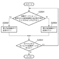
図19はこの実施例に従う記録制御を示すフローチャートである。 FIG. 19 is a flowchart showing recording control according to this embodiment.
まず、ステップS2001では、画像入力部303に入力される画像データに基づき記録される記録画像の主走査方向の最大記録サイズが4インチ以下かどうかを調べる。
First, in step S2001, it is checked whether the maximum recording size in the main scanning direction of a recorded image recorded based on the image data input to the
ここで、そのサイズが4インチ以下であると判断されれば、処理はステップS2002に進み、第1の記録動作で記録を行い、その後、処理はステップS2003に進む。これに対して、そのサイズが4インチより大きいと判断されれば、処理はステップS2004に進み、第2の記録動作で記録を行う。その後、処理はステップS2003に進む。 If it is determined that the size is 4 inches or less, the process proceeds to step S2002, recording is performed by the first recording operation, and then the process proceeds to step S2003. On the other hand, if it is determined that the size is larger than 4 inches, the process proceeds to step S2004, and recording is performed by the second recording operation. Thereafter, the process proceeds to step S2003.
ステップS2003では、次ページ又は次ジョブの画像データがあるかどうかを調べ、さらに画像データがあると判断された場合には、処理はステップS2001に戻って前述の処理を繰返すが、画像データがない場合と判断された場合には、処理は終了する。 In step S2003, it is checked whether there is image data for the next page or the next job. If it is determined that there is more image data, the process returns to step S2001 and repeats the above processing, but there is no image data. If it is determined to be a case, the process ends.
従って以上説明した実施例に従えば、画像データに基づき記録される記録画像の主走査方向のサイズ(つまり、画像データの主走査方向のサイズ)に応じて、記録媒体上の各記録画素内のドット配置であるインク液滴の付着位置を異ならせることで、濃度ムラを十分抑制し、かつ視覚的に粒状感を低減させた高品位な画像を記録することが可能になる。 Therefore, according to the embodiment described above, in each recording pixel on the recording medium according to the size of the recording image recorded based on the image data in the main scanning direction (that is, the size of the image data in the main scanning direction). By differentiating the positions of the ink droplets in the dot arrangement, it is possible to record a high-quality image that sufficiently suppresses uneven density and visually reduces graininess.
なお、この実施例においても、第2の記録動作では、第1の記録動作と比較して副走査方向への記録媒体の搬送量を各走査記録毎に異ならせる制御を行う代わりに、例えば、第2の記録動作でも記録媒体の搬送量は第1の記録動作と同じで、記録ヘッドを走査する主走査方向に関し、記録ヘッドからのインク液滴の吐出タイミングを異ならせても良い。 In this embodiment as well, in the second recording operation, instead of performing control to vary the conveyance amount of the recording medium in the sub-scanning direction for each scanning recording as compared with the first recording operation, for example, In the second recording operation, the transport amount of the recording medium is the same as that in the first recording operation, and the ejection timing of the ink droplets from the recording head may be varied in the main scanning direction in which the recording head is scanned.
また、この実施例では記録画像の主走査方向のサイズ(画像データの主走査方向のサイズ)に応じて各記録画素内の記録ドット配置(インク液滴の付着位置)を異ならせていたが、本発明はこれによって限定されるものではない。例えば、記録画像の副走査方向のサイズに応じて各記録画素内の記録ドット配置(インク液滴の付着位置)を異ならせても良いし、記録画像の主走査方向のサイズと副走査方向のサイズを合計したサイズに応じて各記録画素内の記録ドット配置(インク液滴の付着位置)を異ならせても良い。 Further, in this embodiment, the recording dot arrangement (ink droplet adhesion position) in each recording pixel is varied according to the size of the recording image in the main scanning direction (size of the image data in the main scanning direction). The present invention is not limited thereby. For example, the recording dot arrangement (ink droplet adhesion position) in each recording pixel may be varied according to the size of the recording image in the sub-scanning direction, or the size of the recording image in the main scanning direction and the sub-scanning direction may be different. The recording dot arrangement (ink droplet adhesion position) in each recording pixel may be varied depending on the total size.
図20は記録媒体に記録された画像の副走査方向のサイズと主走査及び副走査方向に関する濃度ムラと粒状感との関係を示す図である。 FIG. 20 is a diagram showing the relationship between the size of the image recorded on the recording medium in the sub-scanning direction, density unevenness in the main scanning and sub-scanning directions, and graininess.
この図は、記録画像の副走査方向のサイズに応じて各記録画素内での記録ドット配置を異ならせて記録を行って得られた画像品質の結果を表わしている。 This figure shows the result of image quality obtained by performing recording by changing the arrangement of the recording dots in each recording pixel in accordance with the size of the recording image in the sub-scanning direction.
図21は記録媒体に記録された画像の主走査及び副走査方向のサイズの合計と主走査及び副走査方向に関する濃度ムラと粒状感との関係を示す図である。 FIG. 21 is a diagram showing the relationship between the total size of the images recorded on the recording medium in the main scanning and sub-scanning directions, density unevenness in the main scanning and sub-scanning directions, and graininess.
この図は、記録画像の主走査及び副走査方向のサイズを合計したサイズに応じて各記録画素内での記録ドット配置を異ならせて記録を行って得られた画像品質の結果を表わしている。 This figure shows the result of image quality obtained by performing recording by changing the recording dot arrangement in each recording pixel according to the total size of the main scanning and sub-scanning directions of the recording image. .
このようにしても、前述の実施例と同様の効果を得ることができる。 Even if it does in this way, the effect similar to the above-mentioned Example can be acquired.
<その他の実施例>
上記第1〜2の実施例では、記録媒体のサイズや画像データのサイズを所定のサイズと比較し、その比較結果に応じて使用するドット配置パターンを異ならせる手法(別の表現をすれば、比較結果に応じて、異なるドット配置で記録する複数の記録動作の中から1つの記録動作を選択する手法)を採用しているが、本発明はこれに限定されるものではない。記録媒体のサイズや画像データのサイズを所定のサイズと比較せずとも、最初から、使用するドット配置パターン(使用する記録動作法)を記録媒体のサイズや画像データのサイズに対応付けておくことで上記比較処理を省略することもできる。
<Other examples>
In the first and second embodiments, the size of the recording medium and the size of the image data are compared with a predetermined size, and the dot arrangement pattern to be used is changed according to the comparison result (in other words, According to the comparison result, a method of selecting one recording operation from a plurality of recording operations for recording with different dot arrangements is employed, but the present invention is not limited to this. Without comparing the size of the recording medium and the size of the image data with a predetermined size, the dot arrangement pattern to be used (the recording operation method to be used) is associated with the size of the recording medium and the size of the image data from the beginning. Thus, the comparison process can be omitted.
例えば、表1のように、記録媒体のサイズに関する情報と使用するドット配置パターンとを対応付けたテーブルを予め作成しておき、記録の際には、記録媒体のサイズに関する情報を取得し、当該取得した情報に対応したドット配置パターンを使用すればよいのである。もちろん、画像データのサイズに関する情報と使用するドット配置パターンとを対応付けたテーブルであってもよいし、画像データおよび記録媒体のサイズに関する情報と使用するドット配置パターンとを対応付けたテーブルであってもよい。 For example, as shown in Table 1, a table in which information about the size of the recording medium is associated with the dot arrangement pattern to be used is created in advance, and when recording, information about the size of the recording medium is acquired, A dot arrangement pattern corresponding to the acquired information may be used. Of course, the table may be a table in which information on the size of the image data is associated with the dot arrangement pattern to be used, or a table in which the information on the size of the image data and the recording medium is associated with the dot arrangement pattern to be used. May be.

また、上述の実施例では、記録媒体のサイズに関する情報や画像データのサイズに関する情報として、3インチ、4インチ、Xインチ等のサイズそのものの値を使用しているが、本発明は、これに限定されるものではない。結果的に、記録媒体のサイズや画像データのサイズに対応するものであればよく、記録媒体のサイズや画像データのサイズを間接的に表した情報であってもよいことは言うまでもない。例えば、4ビットデータでサイズ情報を表すようにしてもよく、「0000」が3インチ、「0001」が4インチ、「0010」が5インチのように定義し、記録媒体のサイズや画像データのサイズを間接的に表した情報を使用する構成であっても良い。また、画像データであれば、画像データのビット数とサイズ情報を対応させておくことも可能である。 In the above-described embodiments, the values of the size itself such as 3 inches, 4 inches, and X inches are used as the information regarding the size of the recording medium and the information regarding the size of the image data. It is not limited. As a result, it is only necessary to correspond to the size of the recording medium and the size of the image data, and it goes without saying that the information may indirectly represent the size of the recording medium and the size of the image data. For example, the size information may be represented by 4-bit data, “0000” is defined as 3 inches, “0001” is defined as 4 inches, and “0010” is defined as 5 inches. It may be configured to use information that indirectly represents the size. In the case of image data, the number of bits of image data can be associated with size information.
以上のように本発明では、記録媒体のサイズに関する情報および/または画像データのサイズに関する情報であれば足り、そのサイズを直接的に表現した情報であっても間接的に表現した情報であってもよい。 As described above, in the present invention, information relating to the size of the recording medium and / or information relating to the size of the image data is sufficient, and even information directly representing the size is information indirectly represented. Also good.
また、上述の実施例では、記録媒体のサイズに関する情報と画像データのサイズとの内、少なくともいずれかに関する情報に基づいて、同数のドットが付着される同一レベルの画素に対して1種類のドット配置パターン(例えば、図7(c)に示されるようなドット配置パターン)を割当てる第1記録動作のモードと、同数のドットが付着される同一レベルの画素に対して複数種類のドット配置パターン(例えば、図10(c)に示されるようなドット配置パターン)を割当てる第2記録動作のモードとを選択する形態について説明したが、本発明はこの形態に限られるものではない。例えば、これら記録モードの選択をユーザが任意に行えるようにした形態であってもよい。この場合、記録装置の操作部306に設けられたスイッチによりモード選択を実行できる形態としてもよいし、記録装置と接続されるホストコンピュータにインストールされたプリンタドライバのプロパティ画面においてモード選択を実行できる形態としてもよい。
In the above-described embodiment, one type of dot is applied to pixels of the same level to which the same number of dots are attached based on information on at least one of the information on the size of the recording medium and the size of the image data. A first recording operation mode in which an arrangement pattern (for example, a dot arrangement pattern as shown in FIG. 7C) is assigned and a plurality of types of dot arrangement patterns (for the same level of pixels to which the same number of dots are attached) For example, the mode of selecting the second recording operation mode to which the dot arrangement pattern (as shown in FIG. 10C) is assigned has been described, but the present invention is not limited to this mode. For example, the recording mode may be arbitrarily selected by the user. In this case, the mode selection may be performed by a switch provided in the
また、以上説明した2つの実施例で使用した記録ヘッドは、副走査方向に解像度600dpiで8個の吐出口を有していた構成であったが、本発明がこれによって限定されるものではないことは言うまでもない。例えば、解像度は1200dpiでも良く、或いは、それ以外の密度でも良く、吐出口数も64個、128個、256個と8個以外の数でも良い。さらに、吐出口の配置構成も図4に示すような構成によって限定されるものではない。 In addition, the recording head used in the two embodiments described above has a configuration in which eight ejection openings are provided at a resolution of 600 dpi in the sub-scanning direction, but the present invention is not limited thereto. Needless to say. For example, the resolution may be 1200 dpi, or a density other than that, and the number of ejection ports may be other than 64, 128, 256, or 8. Furthermore, the arrangement of the discharge ports is not limited to the arrangement shown in FIG.
図22は記録ヘッドの吐出口の配置構成の変形例を示す図である。 FIG. 22 is a diagram showing a modification of the arrangement of the ejection openings of the recording head.
図22が示すように、その配置構成は直線状ではなく、千鳥状に配置されていても良い。 As shown in FIG. 22, the arrangement configuration may be arranged in a staggered manner instead of a linear shape.
また、各インク吐出口から吐出されるインク液滴の大きさもこの実施例では約5plとしたが本発明はこれによって限定されるものではなく、例えば、約2plとより小さくても、また約10plとより大きくても良い。また、吐出インク液滴の体積を約2plとした場合には、画像データは1画素当り600×600dpiの解像度の8ビットのデータとし、0から8までの9レベルに量子化されているとしても良い。 In addition, the size of the ink droplet ejected from each ink ejection port is about 5 pl in this embodiment, but the present invention is not limited to this. For example, the size of the ink droplet is smaller than about 2 pl, or about 10 pl. And larger. Further, when the volume of the ejected ink droplet is about 2 pl, the image data is 8-bit data with a resolution of 600 × 600 dpi per pixel and may be quantized to 9 levels from 0 to 8. good.
さらに、この実施例では、図5に示したように、複数のビットパターンが存在する画素データに対応する量子化レベルでは、複数種類の画素データ中からランダムに1つを選択したが、本発明はこれによって限定されるものではなく、規則的に選択を行っても良い。 Furthermore, in this embodiment, as shown in FIG. 5, at the quantization level corresponding to the pixel data having a plurality of bit patterns, one is randomly selected from a plurality of types of pixel data. Is not limited to this, and the selection may be made regularly.
またさらに、この実施例では1つの記録ヘッドのみに言及して記録動作を説明したが、図1に示したように、Kインク、Cインク、Mインク、Yインクの4色使用してカラー記録を行なう4つの記録ヘッドに対しても本発明を同様に適用し、上述した同様の効果を得ることができることは言うまでもない。 Furthermore, in this embodiment, the recording operation has been described with reference to only one recording head. However, as shown in FIG. 1, color recording is performed using four colors of K ink, C ink, M ink, and Y ink. Needless to say, the present invention can be similarly applied to the four recording heads for performing the above and the same effects as described above can be obtained.
さらに、以上の実施例において、記録ヘッドから吐出される液滴はインクであるとして説明し、さらにインクタンクに収容される液体はインクであるとして説明したが、その収容物はインクに限定されるものではない。例えば、記録画像の定着性や耐水性を高めたり、その画像品質を高めたりするために記録媒体に対して吐出される処理液のようなものがインクタンクに収容されていても良い。 Further, in the above embodiment, the liquid droplets ejected from the recording head have been described as ink, and the liquid stored in the ink tank has been described as ink. However, the storage is limited to ink. It is not a thing. For example, a treatment liquid discharged to the recording medium may be stored in the ink tank in order to improve the fixability and water resistance of the recorded image or to improve the image quality.
以上の実施例は、特にインクジェット記録方式の中でも、インク吐出を行わせるために利用されるエネルギーとして熱エネルギーを発生する手段(例えば電気熱変換体やレーザ光等)を備え、前記熱エネルギーによりインクの状態変化を生起させる方式を用いることが好ましい。 The above embodiment includes means (for example, an electrothermal converter or a laser beam) that generates thermal energy as energy used to perform ink ejection, particularly in the ink jet recording system, and the ink is generated by the thermal energy. It is preferable to use a method for causing the state change.
101 インクタンク
102 記録ヘッド
103 搬送ローラ
104 補助ローラ
105 給紙ローラ
106 キャリッジ
300 CPU
301 ROM
302 RAM
303 画像入力部
304 画像信号処理部
305 バスライン
306 操作部
307 回復系制御部
308 回復系モータ
309 ブレード
310 キャップ
311 ポンプ
312 ダイオードセンサ
313 保温ヒータ
314 ヘッド温度制御回路
315 ヘッド駆動制御回路
316 キャリッジ駆動制御回路
317 搬送制御回路
101
301 ROM
302 RAM
303
Claims (13)
同一の階調レベルの複数の画素を記録するために1種類のドット配置パターンだけを用いることが可能な第1記録動作モードと、同一の階調レベルの複数の画素を記録するために複数種類のドット配置パターンを用いることが可能な第2記録動作モードのうち、前記記録媒体のサイズあるいは画像データのサイズに関する情報に基づいて、1つの記録動作モードを選択する選択工程と、
前記選択工程において選択された1つの記録動作モードを実行する記録工程とを有し、
前記選択工程では、前記情報が示すサイズが所定のサイズ以下の場合には前記第1記録動作モードを選択し、前記情報が示すサイズが前記所定のサイズよりも大きい場合には前記第2の記録動作モードを選択することを特徴とする記録方法。 A recording method for performing recording by forming dots on a recording medium using a recording head based on a dot arrangement pattern corresponding to the gradation level of each pixel,
A plurality of types in order to record the same and one first recording operation mode that can be used only dot arrangement pattern to record a plurality of pixels of gray levels, a plurality of pixels of the same gray level A selection step of selecting one recording operation mode based on information on the size of the recording medium or the size of the image data among the second recording operation modes that can use the dot arrangement pattern of
Have a recording step of executing one recording operation mode selected in said selecting step,
In the selection step, when the size indicated by the information is equal to or smaller than a predetermined size, the first recording operation mode is selected, and when the size indicated by the information is larger than the predetermined size, the second recording is performed. A recording method comprising selecting an operation mode .
前記記録媒体のサイズおよび画像データのサイズの少なくとも一方に関する情報に応じて、所定数のドットを形成するための1種類のドット配置パターンを所定の階調レベルの画素に割り当て、記録を行なうための第1記録動作モード、或は、前記所定数のドットを形成するためのドット配置パターンとして、ドット配置が異なる複数種類のドット配置パターンを前記所定の階調レベルの画素に割り当て、記録を行なうための第2記録動作モードを設定する設定工程と、
前記設定工程において設定された記録動作モードに従って記録を行う記録工程とを有し、
前記設定工程では、前記情報が示すサイズが所定のサイズ以下の場合には前記第1記録動作モードを設定し、前記情報が示すサイズが前記所定のサイズよりも大きい場合には前記第2の記録動作モードを設定することを特徴とする記録方法。 A recording method for recording by forming dots on a recording medium using a recording head,
In accordance with information relating to at least one of the size of the recording medium and the size of image data, one kind of dot arrangement pattern for forming a predetermined number of dots is assigned to pixels of a predetermined gradation level for recording In order to perform recording by assigning a plurality of types of dot arrangement patterns having different dot arrangements to the pixels of the predetermined gradation level as the first recording operation mode or the dot arrangement patterns for forming the predetermined number of dots. A setting step for setting the second recording operation mode ;
A recording step of performing recording according to the recording operation mode set in the setting step ,
In the setting step , when the size indicated by the information is equal to or smaller than a predetermined size, the first recording operation mode is set. When the size indicated by the information is larger than the predetermined size, the second recording operation mode is set. A recording method characterized by setting a recording operation mode .
前記所定の階調レベルの画素に割当てられる前記1種類のドット配置パターンは、画素内の同じ位置に前記所定数のドットを形成するためのパターンであり、
前記所定の階調レベルの画素に割当てられる前記複数種類のドット配置パターンは、画素内の異なる位置に前記所定数のドットを形成するためのパターンを含むことを特徴とする請求項2に記載の記録方法。 The predetermined number is 2 or more,
The one kind of dot arrangement pattern assigned to the pixel of the predetermined gradation level is a pattern for forming the predetermined number of dots at the same position in the pixel,
3. The plurality of types of dot arrangement patterns assigned to the pixels of the predetermined gradation level include patterns for forming the predetermined number of dots at different positions in the pixels. Recording method.
前記所定の階調レベルの画素に割当てられる前記複数種類のドット配置パターンは、画素内の異なる位置に前記所定数のドットを形成するためのパターンと、画素内の同じ位置に前記所定数のドットを形成するためのパターンとを含むことを特徴とする請求項2に記載の記録方法。 The predetermined number is 2 or more,
Said predetermined plurality of types of dot arrangement patterns assigned to the gradation level of the pixel, the predetermined number of dots and patterns for forming the predetermined number of dots at different positions in the pixel in the same position in a pixel The recording method according to claim 2, further comprising: a pattern for forming a pattern.
前記記録媒体のサイズに関する情報に基づいて、同一の階調レベルの複数の画素を記録するために1種類のドット配置パターンだけを用いることが可能な第1記録動作モードと、同一の階調レベルの複数の画素を記録するために複数種類のドット配置パターンを用いることが可能な第2記録動作モードとを選択的に実行するための手段を有し、
前記手段は、前記情報が示すサイズが所定のサイズ以下の場合には前記第1記録動作モードを選択して実行し、前記情報が示すサイズが前記所定のサイズよりも大きい場合には前記第2の記録動作モードを選択して実行することを特徴とする記録装置。 A recording apparatus that performs recording by forming dots on a recording medium using a recording head based on a dot arrangement pattern corresponding to the gradation level of each pixel,
The first gradation operation mode in which only one kind of dot arrangement pattern can be used to record a plurality of pixels having the same gradation level based on the information on the size of the recording medium, and the same gradation level have a means for selectively executing a plurality of types second recording mode of operation that can be used dot arrangement pattern to record a plurality of pixels,
The means selects and executes the first recording operation mode when the size indicated by the information is equal to or smaller than a predetermined size, and the second mode when the size indicated by the information is larger than the predetermined size. A recording apparatus , wherein the recording operation mode is selected and executed .
前記画像データのサイズに関する情報に基づいて、同一の階調レベルの複数の画素を記録するために、1種類のドット配置パターンだけを用いることが可能な第1記録動作モードと、同一の階調レベルの複数の画素を記録するために複数種類のドット配置パターンを用いることが可能な第2記録動作モードとを選択的に実行するための手段を有し、
前記手段は、前記情報が示すサイズが所定のサイズ以下の場合には前記第1記録動作モードを選択して実行し、前記情報が示すサイズが前記所定のサイズよりも大きい場合には前記第2の記録動作モードを選択して実行することを特徴とする記録装置。 A recording apparatus that performs recording by forming dots on a recording medium using a recording head based on a dot arrangement pattern corresponding to the gradation level of each pixel of image data ,
The first recording operation mode in which only one kind of dot arrangement pattern can be used to record a plurality of pixels having the same gradation level based on the information on the size of the image data, and the same gradation have a means for selectively executing a plurality of types second recording mode of operation that can be used dot arrangement pattern to record a plurality of pixels of level,
The means selects and executes the first recording operation mode when the size indicated by the information is equal to or smaller than a predetermined size, and the second mode when the size indicated by the information is larger than the predetermined size. A recording apparatus , wherein the recording operation mode is selected and executed .
前記記録媒体のサイズに関する情報に応じて、所定数のドットを形成するための1種類のドット配置パターンを所定の階調レベルの複数の画素に割り当て、記録を行なうための第1記録動作モードと、前記所定数のドットを形成するためのドット配置パターンとして、ドット配置が異なる複数種類のドット配置パターンを前記所定の階調レベルの複数の画素に割り当て、記録を行なうための第2記録動作モードとを選択的に実行するための手段を有し、
前記手段は、前記情報が示すサイズが所定のサイズ以下の場合には前記第1記録動作モードを選択して実行し、前記情報が示すサイズが前記所定のサイズよりも大きい場合には前記第2の記録動作モードを選択して実行することを特徴とする記録装置。 A recording apparatus that performs recording by ejecting dots onto a recording medium using a recording head,
A first recording operation mode for performing recording by assigning one kind of dot arrangement pattern for forming a predetermined number of dots to a plurality of pixels of a predetermined gradation level in accordance with information relating to the size of the recording medium ; as the dot arrangement pattern for forming a predetermined number of dots, assign a plurality of types of dot arrangement patterns dot arrangement different to a plurality of pixels of the predetermined gray level, the for cormorants row records have a means for performing the second recording mode of operation selectively,
The means selects and executes the first recording operation mode when the size indicated by the information is equal to or smaller than a predetermined size, and the second mode when the size indicated by the information is larger than the predetermined size. A recording apparatus , wherein the recording operation mode is selected and executed .
前記画像データのサイズに関する情報に応じて、所定数のドットを形成するための1種類のドット配置パターンを所定の階調レベルの画素に割り当て、記録を行なうための第1記録動作モードと、前記所定数のドットを形成するためのドット配置パターンとして、ドット配置が異なる複数種類のドット配置パターンを前記所定の階調レベルの画素に割り当て記録を行なうための第2記録動作モードとを選択的に実行するための手段を有し、
前記手段は、前記情報が示すサイズが所定のサイズ以下の場合には前記第1記録動作モードを選択して実行し、前記情報が示すサイズが前記所定のサイズよりも大きい場合には前記第2の記録動作モードを選択して実行することを特徴とする記録装置。 A recording apparatus that performs recording by forming dots on a recording medium by a recording head based on image data ,
A first recording operation mode for performing recording by allocating one kind of dot arrangement pattern for forming a predetermined number of dots to pixels of a predetermined gradation level in accordance with information relating to the size of the image data ; as the dot arrangement pattern for forming a predetermined number of dots, selecting a second recording operation mode for Nau row allocation records a plurality of types of dot arrangement patterns dot arrangement different pixels of the predetermined gray level Means for performing
The means selects and executes the first recording operation mode when the size indicated by the information is equal to or smaller than a predetermined size, and the second mode when the size indicated by the information is larger than the predetermined size. A recording apparatus , wherein the recording operation mode is selected and executed .
前記記録媒体を前記第1の方向とは異なる第2の方向に搬送する搬送手段とをさらに有し、
前記記録媒体のサイズは、前記第1の方向のサイズ、前記第2の方向のサイズ、及び前記第1及び第2の方向のサイズの合計の内のいずれかであることを特徴とする請求項5又は7に記載の記録装置。 Scanning means for reciprocatingly scanning the recording head in a first direction;
Transport means for transporting the recording medium in a second direction different from the first direction;
The size of the recording medium is any one of a size in the first direction, a size in the second direction, and a total size in the first and second directions. The recording apparatus according to 5 or 7 .
前記記録媒体を前記第1の方向とは異なる第2の方向に搬送する搬送手段とをさらに有し、Transport means for transporting the recording medium in a second direction different from the first direction;
前記画像データのサイズは、前記第1の方向のサイズ、前記第2の方向のサイズ、及び前記第1及び第2の方向のサイズの合計の内のいずれかであることを特徴とする請求項6又は8に記載の記録装置。The size of the image data is any one of a size in the first direction, a size in the second direction, and a total size in the first and second directions. The recording apparatus according to 6 or 8.
前記所定の階調レベルの画素に割当てられる前記1種類のドット配置パターンは、画素内の同じ位置に前記所定数のドットを形成するためのパターンであり、
前記所定の階調レベルの画素に割当てられる前記複数種類のドット配置パターンは、画素内の異なる位置に前記所定数のドットを形成するためのパターンを含むことを特徴とする請求項7又は8に記載の記録装置。 The predetermined number is 2 or more,
The one kind of dot arrangement pattern assigned to the pixel of the predetermined gradation level is a pattern for forming the predetermined number of dots at the same position in the pixel,
It said predetermined plurality of types of dot arrangement patterns assigned to the gradation level of the pixel, to claim 7 or 8, characterized in that it comprises a pattern for forming a predetermined number of dots at different positions in a pixel The recording device described.
前記所定の階調レベルの画素に割当てられる前記複数種類のドット配置パターンは、画素内の異なる位置に所定数のドットを形成するためのパターンと、画素内の同じ位置に前記所定数のドットを形成するためのパターンとを含むことを特徴とする請求項7又は8に記載の記録装置。 The predetermined number is 2 or more,
Said predetermined plurality of types of dot arrangement patterns assigned to the gradation level of the pixel has a pattern for forming a predetermined number of dots at different positions in the pixel, the predetermined number of dots in the same position in a pixel The recording apparatus according to claim 7 , further comprising: a pattern to be formed .
前記画素に対して前記記録ヘッドを複数回走査させ、該複数回の走査によって前記画素への記録を完成させるマルチパス記録方式によって、前記第1及び第2の記録動作モードを実行可能であることを特徴とする請求項5乃至12のいずれか1項に記載の記録装置。The first and second recording operation modes can be executed by a multi-pass recording method in which the recording head is scanned a plurality of times with respect to the pixels, and the recording to the pixels is completed by the plurality of scannings. The recording apparatus according to claim 5, wherein the recording apparatus is a recording apparatus.
Priority Applications (3)
| Application Number | Priority Date | Filing Date | Title |
|---|---|---|---|
| JP2004015521A JP4235569B2 (en) | 2003-02-26 | 2004-01-23 | Recording method and recording apparatus |
| US10/784,262 US7185964B2 (en) | 2003-02-26 | 2004-02-24 | Printing method and printing apparatus |
| CNB2004100066378A CN100368196C (en) | 2003-02-26 | 2004-02-25 | Recording method and recorder |
Applications Claiming Priority (2)
| Application Number | Priority Date | Filing Date | Title |
|---|---|---|---|
| JP2003049972 | 2003-02-26 | ||
| JP2004015521A JP4235569B2 (en) | 2003-02-26 | 2004-01-23 | Recording method and recording apparatus |
Publications (3)
| Publication Number | Publication Date |
|---|---|
| JP2004276596A JP2004276596A (en) | 2004-10-07 |
| JP2004276596A5 JP2004276596A5 (en) | 2006-01-26 |
| JP4235569B2 true JP4235569B2 (en) | 2009-03-11 |
Family
ID=32871232
Family Applications (1)
| Application Number | Title | Priority Date | Filing Date |
|---|---|---|---|
| JP2004015521A Expired - Fee Related JP4235569B2 (en) | 2003-02-26 | 2004-01-23 | Recording method and recording apparatus |
Country Status (3)
| Country | Link |
|---|---|
| US (1) | US7185964B2 (en) |
| JP (1) | JP4235569B2 (en) |
| CN (1) | CN100368196C (en) |
Families Citing this family (10)
| Publication number | Priority date | Publication date | Assignee | Title |
|---|---|---|---|---|
| JP2008168620A (en) * | 2006-12-11 | 2008-07-24 | Canon Inc | Inkjet recorder and inkjet recording method |
| US20090040559A1 (en) * | 2007-08-10 | 2009-02-12 | Shuji Hamada | Image forming apparatus, image forming method, and image processing program |
| JP5409246B2 (en) * | 2009-10-09 | 2014-02-05 | キヤノン株式会社 | Ink jet recording apparatus and recording head temperature control method |
| JP5540794B2 (en) | 2010-03-18 | 2014-07-02 | セイコーエプソン株式会社 | Liquid ejecting method and liquid ejecting apparatus |
| JP5783684B2 (en) * | 2010-05-24 | 2015-09-24 | キヤノン株式会社 | Image processing apparatus and image processing method |
| JP5875573B2 (en) | 2013-11-22 | 2016-03-02 | キヤノン株式会社 | Recording apparatus and bubble discharging method thereof |
| JP2015122618A (en) * | 2013-12-24 | 2015-07-02 | キヤノン株式会社 | Information processing device, information processing method, and program |
| JP7492195B2 (en) | 2020-10-29 | 2024-05-29 | ブラザー工業株式会社 | Control device, computer program |
| JP2022151262A (en) * | 2021-03-26 | 2022-10-07 | セイコーエプソン株式会社 | Liquid discharge device |
| JP2022184353A (en) | 2021-06-01 | 2022-12-13 | キヤノン株式会社 | Recording device, control device, and program |
Family Cites Families (13)
| Publication number | Priority date | Publication date | Assignee | Title |
|---|---|---|---|---|
| US4930018A (en) * | 1988-12-02 | 1990-05-29 | Hewlett-Packard Company | Method and system for enhancing the quality of both color and black and white images produced by ink jet printers |
| US6109720A (en) | 1993-04-28 | 2000-08-29 | Canon Kabushiki Kaisha | Method and apparatus for ink-jet recording with inks having different densities |
| US6793308B2 (en) * | 1993-05-24 | 2004-09-21 | Canon Kabushiki Kaisha | Ink-jet recording apparatus and ink-jet recording method using inks of different densities, and recorded articles |
| JP3423491B2 (en) | 1995-07-28 | 2003-07-07 | キヤノン株式会社 | Image processing method, printing method, image processing device, printing device, and display device |
| JP3559633B2 (en) | 1995-12-05 | 2004-09-02 | キヤノン株式会社 | Printing apparatus and ink jet printing method |
| JPH1067127A (en) | 1996-04-23 | 1998-03-10 | Canon Inc | Ink jet recording device and image processing method |
| US6682170B2 (en) * | 1997-04-07 | 2004-01-27 | Minolta Co., Ltd. | Image forming apparatus |
| JPH1178070A (en) * | 1997-09-17 | 1999-03-23 | Seiko Epson Corp | Ink density fixing method and image output apparatus |
| JPH11320919A (en) * | 1998-05-18 | 1999-11-24 | Seiko Epson Corp | Image output apparatus |
| US6196661B1 (en) | 1998-07-30 | 2001-03-06 | Canon Kabushiki Kaisha | Serial recording apparatus |
| JP2000101858A (en) * | 1998-09-18 | 2000-04-07 | Toshiba Tec Corp | Image forming device |
| US6877833B2 (en) * | 2001-01-31 | 2005-04-12 | Canon Kabushiki Kaisha | Printing data producing method for printing apparatus |
| JP3970096B2 (en) | 2001-06-07 | 2007-09-05 | キヤノン株式会社 | Inkjet recording method and inkjet recording apparatus |
-
2004
- 2004-01-23 JP JP2004015521A patent/JP4235569B2/en not_active Expired - Fee Related
- 2004-02-24 US US10/784,262 patent/US7185964B2/en not_active Expired - Fee Related
- 2004-02-25 CN CNB2004100066378A patent/CN100368196C/en not_active Expired - Fee Related
Also Published As
| Publication number | Publication date |
|---|---|
| CN1530224A (en) | 2004-09-22 |
| JP2004276596A (en) | 2004-10-07 |
| US7185964B2 (en) | 2007-03-06 |
| US20040165022A1 (en) | 2004-08-26 |
| CN100368196C (en) | 2008-02-13 |
Similar Documents
| Publication | Publication Date | Title |
|---|---|---|
| JP4533346B2 (en) | Ink jet recording apparatus, recording control method for ink jet recording apparatus, program, and storage medium | |
| JP3414325B2 (en) | Printing device and recording medium | |
| JP4182123B2 (en) | Inkjet recording head and inkjet recording apparatus | |
| JP2005169754A (en) | Ink jet recorder and ink jet recording method | |
| JP3970096B2 (en) | Inkjet recording method and inkjet recording apparatus | |
| JP4298127B2 (en) | Image recording method, image recording apparatus, method for controlling image recording apparatus, computer-readable storage medium, and image processing method | |
| US6846066B2 (en) | Recording apparatus for recording image by expanding the image in dot pattern | |
| JP4385626B2 (en) | Image processing apparatus, image processing method, and image processing program | |
| JP5072349B2 (en) | Image forming apparatus and control method thereof | |
| EP1288002B1 (en) | Method and apparatus of optimizing discrete drop volumes for multidrop capable inkjet printers | |
| JP4235569B2 (en) | Recording method and recording apparatus | |
| JP2012066576A (en) | Inkjet recording apparatus and recording method | |
| US8976416B2 (en) | Image processing apparatus and method thereof | |
| JP2005169940A (en) | Ink-jet recording device and ink-jet recording method | |
| JP4979485B2 (en) | Inkjet recording device | |
| JP5776348B2 (en) | Image forming apparatus and image forming method | |
| JP2003094693A (en) | Printer and recording medium | |
| JP2006240307A (en) | Printing device, printing method, and recording medium | |
| JP3176124B2 (en) | Ink jet recording apparatus and recording method of the apparatus | |
| JP2006056080A (en) | Data processor, data processing method, inkjet recording apparatus, and inkjet recording method | |
| JP2006305993A (en) | Inkjet recorder, apparatus for supplying recorder with image data, and method for controlling recorder | |
| JP2006224616A (en) | Recording method and recording system | |
| JP2008162096A (en) | Image forming apparatus and its control method | |
| JP2004322374A (en) | Image formation device and image formation method | |
| JP2006231735A (en) | Image processor, image processing method, control program, and recorder |
Legal Events
| Date | Code | Title | Description |
|---|---|---|---|
| A521 | Written amendment |
Free format text: JAPANESE INTERMEDIATE CODE: A523 Effective date: 20051207 |
|
| A621 | Written request for application examination |
Free format text: JAPANESE INTERMEDIATE CODE: A621 Effective date: 20051207 |
|
| A977 | Report on retrieval |
Free format text: JAPANESE INTERMEDIATE CODE: A971007 Effective date: 20080723 |
|
| A131 | Notification of reasons for refusal |
Free format text: JAPANESE INTERMEDIATE CODE: A131 Effective date: 20080725 |
|
| A521 | Written amendment |
Free format text: JAPANESE INTERMEDIATE CODE: A523 Effective date: 20080912 |
|
| TRDD | Decision of grant or rejection written | ||
| A01 | Written decision to grant a patent or to grant a registration (utility model) |
Free format text: JAPANESE INTERMEDIATE CODE: A01 Effective date: 20081205 |
|
| A01 | Written decision to grant a patent or to grant a registration (utility model) |
Free format text: JAPANESE INTERMEDIATE CODE: A01 |
|
| A61 | First payment of annual fees (during grant procedure) |
Free format text: JAPANESE INTERMEDIATE CODE: A61 Effective date: 20081215 |
|
| FPAY | Renewal fee payment (event date is renewal date of database) |
Free format text: PAYMENT UNTIL: 20111219 Year of fee payment: 3 |
|
| R150 | Certificate of patent or registration of utility model |
Free format text: JAPANESE INTERMEDIATE CODE: R150 |
|
| FPAY | Renewal fee payment (event date is renewal date of database) |
Free format text: PAYMENT UNTIL: 20121219 Year of fee payment: 4 |
|
| FPAY | Renewal fee payment (event date is renewal date of database) |
Free format text: PAYMENT UNTIL: 20131219 Year of fee payment: 5 |
|
| LAPS | Cancellation because of no payment of annual fees |