JP4207695B2 - EGR control device for engine - Google Patents
EGR control device for engine Download PDFInfo
- Publication number
- JP4207695B2 JP4207695B2 JP2003270339A JP2003270339A JP4207695B2 JP 4207695 B2 JP4207695 B2 JP 4207695B2 JP 2003270339 A JP2003270339 A JP 2003270339A JP 2003270339 A JP2003270339 A JP 2003270339A JP 4207695 B2 JP4207695 B2 JP 4207695B2
- Authority
- JP
- Japan
- Prior art keywords
- passage
- egr
- intake
- engine
- flow path
- Prior art date
- Legal status (The legal status is an assumption and is not a legal conclusion. Google has not performed a legal analysis and makes no representation as to the accuracy of the status listed.)
- Expired - Fee Related
Links
Images


Classifications
-
- F—MECHANICAL ENGINEERING; LIGHTING; HEATING; WEAPONS; BLASTING
- F02—COMBUSTION ENGINES; HOT-GAS OR COMBUSTION-PRODUCT ENGINE PLANTS
- F02M—SUPPLYING COMBUSTION ENGINES IN GENERAL WITH COMBUSTIBLE MIXTURES OR CONSTITUENTS THEREOF
- F02M35/00—Combustion-air cleaners, air intakes, intake silencers, or induction systems specially adapted for, or arranged on, internal-combustion engines
- F02M35/10—Air intakes; Induction systems
- F02M35/104—Intake manifolds
- F02M35/108—Intake manifolds with primary and secondary intake passages
-
- F—MECHANICAL ENGINEERING; LIGHTING; HEATING; WEAPONS; BLASTING
- F02—COMBUSTION ENGINES; HOT-GAS OR COMBUSTION-PRODUCT ENGINE PLANTS
- F02B—INTERNAL-COMBUSTION PISTON ENGINES; COMBUSTION ENGINES IN GENERAL
- F02B31/00—Modifying induction systems for imparting a rotation to the charge in the cylinder
- F02B31/04—Modifying induction systems for imparting a rotation to the charge in the cylinder by means within the induction channel, e.g. deflectors
- F02B31/06—Movable means, e.g. butterfly valves
- F02B31/08—Movable means, e.g. butterfly valves having multiple air inlets, i.e. having main and auxiliary intake passages
- F02B31/085—Movable means, e.g. butterfly valves having multiple air inlets, i.e. having main and auxiliary intake passages having two inlet valves
-
- F—MECHANICAL ENGINEERING; LIGHTING; HEATING; WEAPONS; BLASTING
- F02—COMBUSTION ENGINES; HOT-GAS OR COMBUSTION-PRODUCT ENGINE PLANTS
- F02M—SUPPLYING COMBUSTION ENGINES IN GENERAL WITH COMBUSTIBLE MIXTURES OR CONSTITUENTS THEREOF
- F02M26/00—Engine-pertinent apparatus for adding exhaust gases to combustion-air, main fuel or fuel-air mixture, e.g. by exhaust gas recirculation [EGR] systems
- F02M26/02—EGR systems specially adapted for supercharged engines
- F02M26/04—EGR systems specially adapted for supercharged engines with a single turbocharger
- F02M26/05—High pressure loops, i.e. wherein recirculated exhaust gas is taken out from the exhaust system upstream of the turbine and reintroduced into the intake system downstream of the compressor
-
- F—MECHANICAL ENGINEERING; LIGHTING; HEATING; WEAPONS; BLASTING
- F02—COMBUSTION ENGINES; HOT-GAS OR COMBUSTION-PRODUCT ENGINE PLANTS
- F02M—SUPPLYING COMBUSTION ENGINES IN GENERAL WITH COMBUSTIBLE MIXTURES OR CONSTITUENTS THEREOF
- F02M26/00—Engine-pertinent apparatus for adding exhaust gases to combustion-air, main fuel or fuel-air mixture, e.g. by exhaust gas recirculation [EGR] systems
- F02M26/02—EGR systems specially adapted for supercharged engines
- F02M26/04—EGR systems specially adapted for supercharged engines with a single turbocharger
- F02M26/06—Low pressure loops, i.e. wherein recirculated exhaust gas is taken out from the exhaust downstream of the turbocharger turbine and reintroduced into the intake system upstream of the compressor
-
- F—MECHANICAL ENGINEERING; LIGHTING; HEATING; WEAPONS; BLASTING
- F02—COMBUSTION ENGINES; HOT-GAS OR COMBUSTION-PRODUCT ENGINE PLANTS
- F02M—SUPPLYING COMBUSTION ENGINES IN GENERAL WITH COMBUSTIBLE MIXTURES OR CONSTITUENTS THEREOF
- F02M26/00—Engine-pertinent apparatus for adding exhaust gases to combustion-air, main fuel or fuel-air mixture, e.g. by exhaust gas recirculation [EGR] systems
- F02M26/02—EGR systems specially adapted for supercharged engines
- F02M26/04—EGR systems specially adapted for supercharged engines with a single turbocharger
- F02M26/07—Mixed pressure loops, i.e. wherein recirculated exhaust gas is either taken out upstream of the turbine and reintroduced upstream of the compressor, or is taken out downstream of the turbine and reintroduced downstream of the compressor
-
- F—MECHANICAL ENGINEERING; LIGHTING; HEATING; WEAPONS; BLASTING
- F02—COMBUSTION ENGINES; HOT-GAS OR COMBUSTION-PRODUCT ENGINE PLANTS
- F02M—SUPPLYING COMBUSTION ENGINES IN GENERAL WITH COMBUSTIBLE MIXTURES OR CONSTITUENTS THEREOF
- F02M26/00—Engine-pertinent apparatus for adding exhaust gases to combustion-air, main fuel or fuel-air mixture, e.g. by exhaust gas recirculation [EGR] systems
- F02M26/02—EGR systems specially adapted for supercharged engines
- F02M26/08—EGR systems specially adapted for supercharged engines for engines having two or more intake charge compressors or exhaust gas turbines, e.g. a turbocharger combined with an additional compressor
-
- F—MECHANICAL ENGINEERING; LIGHTING; HEATING; WEAPONS; BLASTING
- F02—COMBUSTION ENGINES; HOT-GAS OR COMBUSTION-PRODUCT ENGINE PLANTS
- F02M—SUPPLYING COMBUSTION ENGINES IN GENERAL WITH COMBUSTIBLE MIXTURES OR CONSTITUENTS THEREOF
- F02M26/00—Engine-pertinent apparatus for adding exhaust gases to combustion-air, main fuel or fuel-air mixture, e.g. by exhaust gas recirculation [EGR] systems
- F02M26/13—Arrangement or layout of EGR passages, e.g. in relation to specific engine parts or for incorporation of accessories
- F02M26/22—Arrangement or layout of EGR passages, e.g. in relation to specific engine parts or for incorporation of accessories with coolers in the recirculation passage
- F02M26/23—Layout, e.g. schematics
-
- F—MECHANICAL ENGINEERING; LIGHTING; HEATING; WEAPONS; BLASTING
- F02—COMBUSTION ENGINES; HOT-GAS OR COMBUSTION-PRODUCT ENGINE PLANTS
- F02M—SUPPLYING COMBUSTION ENGINES IN GENERAL WITH COMBUSTIBLE MIXTURES OR CONSTITUENTS THEREOF
- F02M26/00—Engine-pertinent apparatus for adding exhaust gases to combustion-air, main fuel or fuel-air mixture, e.g. by exhaust gas recirculation [EGR] systems
- F02M26/13—Arrangement or layout of EGR passages, e.g. in relation to specific engine parts or for incorporation of accessories
- F02M26/22—Arrangement or layout of EGR passages, e.g. in relation to specific engine parts or for incorporation of accessories with coolers in the recirculation passage
- F02M26/29—Constructional details of the coolers, e.g. pipes, plates, ribs, insulation or materials
- F02M26/30—Connections of coolers to other devices, e.g. to valves, heaters, compressors or filters; Coolers characterised by their location on the engine
-
- F—MECHANICAL ENGINEERING; LIGHTING; HEATING; WEAPONS; BLASTING
- F02—COMBUSTION ENGINES; HOT-GAS OR COMBUSTION-PRODUCT ENGINE PLANTS
- F02M—SUPPLYING COMBUSTION ENGINES IN GENERAL WITH COMBUSTIBLE MIXTURES OR CONSTITUENTS THEREOF
- F02M26/00—Engine-pertinent apparatus for adding exhaust gases to combustion-air, main fuel or fuel-air mixture, e.g. by exhaust gas recirculation [EGR] systems
- F02M26/13—Arrangement or layout of EGR passages, e.g. in relation to specific engine parts or for incorporation of accessories
- F02M26/34—Arrangement or layout of EGR passages, e.g. in relation to specific engine parts or for incorporation of accessories with compressors, turbines or the like in the recirculation passage
-
- F—MECHANICAL ENGINEERING; LIGHTING; HEATING; WEAPONS; BLASTING
- F02—COMBUSTION ENGINES; HOT-GAS OR COMBUSTION-PRODUCT ENGINE PLANTS
- F02M—SUPPLYING COMBUSTION ENGINES IN GENERAL WITH COMBUSTIBLE MIXTURES OR CONSTITUENTS THEREOF
- F02M26/00—Engine-pertinent apparatus for adding exhaust gases to combustion-air, main fuel or fuel-air mixture, e.g. by exhaust gas recirculation [EGR] systems
- F02M26/13—Arrangement or layout of EGR passages, e.g. in relation to specific engine parts or for incorporation of accessories
- F02M26/36—Arrangement or layout of EGR passages, e.g. in relation to specific engine parts or for incorporation of accessories with means for adding fluids other than exhaust gas to the recirculation passage; with reformers
-
- F—MECHANICAL ENGINEERING; LIGHTING; HEATING; WEAPONS; BLASTING
- F02—COMBUSTION ENGINES; HOT-GAS OR COMBUSTION-PRODUCT ENGINE PLANTS
- F02M—SUPPLYING COMBUSTION ENGINES IN GENERAL WITH COMBUSTIBLE MIXTURES OR CONSTITUENTS THEREOF
- F02M26/00—Engine-pertinent apparatus for adding exhaust gases to combustion-air, main fuel or fuel-air mixture, e.g. by exhaust gas recirculation [EGR] systems
- F02M26/13—Arrangement or layout of EGR passages, e.g. in relation to specific engine parts or for incorporation of accessories
- F02M26/37—Arrangement or layout of EGR passages, e.g. in relation to specific engine parts or for incorporation of accessories with temporary storage of recirculated exhaust gas
-
- F—MECHANICAL ENGINEERING; LIGHTING; HEATING; WEAPONS; BLASTING
- F02—COMBUSTION ENGINES; HOT-GAS OR COMBUSTION-PRODUCT ENGINE PLANTS
- F02M—SUPPLYING COMBUSTION ENGINES IN GENERAL WITH COMBUSTIBLE MIXTURES OR CONSTITUENTS THEREOF
- F02M26/00—Engine-pertinent apparatus for adding exhaust gases to combustion-air, main fuel or fuel-air mixture, e.g. by exhaust gas recirculation [EGR] systems
- F02M26/13—Arrangement or layout of EGR passages, e.g. in relation to specific engine parts or for incorporation of accessories
- F02M26/38—Arrangement or layout of EGR passages, e.g. in relation to specific engine parts or for incorporation of accessories with two or more EGR valves disposed in parallel
-
- F—MECHANICAL ENGINEERING; LIGHTING; HEATING; WEAPONS; BLASTING
- F02—COMBUSTION ENGINES; HOT-GAS OR COMBUSTION-PRODUCT ENGINE PLANTS
- F02M—SUPPLYING COMBUSTION ENGINES IN GENERAL WITH COMBUSTIBLE MIXTURES OR CONSTITUENTS THEREOF
- F02M26/00—Engine-pertinent apparatus for adding exhaust gases to combustion-air, main fuel or fuel-air mixture, e.g. by exhaust gas recirculation [EGR] systems
- F02M26/13—Arrangement or layout of EGR passages, e.g. in relation to specific engine parts or for incorporation of accessories
- F02M26/41—Arrangement or layout of EGR passages, e.g. in relation to specific engine parts or for incorporation of accessories characterised by the arrangement of the recirculation passage in relation to the engine, e.g. to cylinder heads, liners, spark plugs or manifolds; characterised by the arrangement of the recirculation passage in relation to specially adapted combustion chambers
-
- F—MECHANICAL ENGINEERING; LIGHTING; HEATING; WEAPONS; BLASTING
- F02—COMBUSTION ENGINES; HOT-GAS OR COMBUSTION-PRODUCT ENGINE PLANTS
- F02M—SUPPLYING COMBUSTION ENGINES IN GENERAL WITH COMBUSTIBLE MIXTURES OR CONSTITUENTS THEREOF
- F02M26/00—Engine-pertinent apparatus for adding exhaust gases to combustion-air, main fuel or fuel-air mixture, e.g. by exhaust gas recirculation [EGR] systems
- F02M26/13—Arrangement or layout of EGR passages, e.g. in relation to specific engine parts or for incorporation of accessories
- F02M26/42—Arrangement or layout of EGR passages, e.g. in relation to specific engine parts or for incorporation of accessories having two or more EGR passages; EGR systems specially adapted for engines having two or more cylinders
-
- F—MECHANICAL ENGINEERING; LIGHTING; HEATING; WEAPONS; BLASTING
- F02—COMBUSTION ENGINES; HOT-GAS OR COMBUSTION-PRODUCT ENGINE PLANTS
- F02M—SUPPLYING COMBUSTION ENGINES IN GENERAL WITH COMBUSTIBLE MIXTURES OR CONSTITUENTS THEREOF
- F02M26/00—Engine-pertinent apparatus for adding exhaust gases to combustion-air, main fuel or fuel-air mixture, e.g. by exhaust gas recirculation [EGR] systems
- F02M26/52—Systems for actuating EGR valves
- F02M26/55—Systems for actuating EGR valves using vacuum actuators
- F02M26/56—Systems for actuating EGR valves using vacuum actuators having pressure modulation valves
- F02M26/57—Systems for actuating EGR valves using vacuum actuators having pressure modulation valves using electronic means, e.g. electromagnetic valves
-
- F—MECHANICAL ENGINEERING; LIGHTING; HEATING; WEAPONS; BLASTING
- F02—COMBUSTION ENGINES; HOT-GAS OR COMBUSTION-PRODUCT ENGINE PLANTS
- F02M—SUPPLYING COMBUSTION ENGINES IN GENERAL WITH COMBUSTIBLE MIXTURES OR CONSTITUENTS THEREOF
- F02M35/00—Combustion-air cleaners, air intakes, intake silencers, or induction systems specially adapted for, or arranged on, internal-combustion engines
- F02M35/10—Air intakes; Induction systems
- F02M35/1015—Air intakes; Induction systems characterised by the engine type
- F02M35/10157—Supercharged engines
-
- F—MECHANICAL ENGINEERING; LIGHTING; HEATING; WEAPONS; BLASTING
- F02—COMBUSTION ENGINES; HOT-GAS OR COMBUSTION-PRODUCT ENGINE PLANTS
- F02M—SUPPLYING COMBUSTION ENGINES IN GENERAL WITH COMBUSTIBLE MIXTURES OR CONSTITUENTS THEREOF
- F02M35/00—Combustion-air cleaners, air intakes, intake silencers, or induction systems specially adapted for, or arranged on, internal-combustion engines
- F02M35/10—Air intakes; Induction systems
- F02M35/10209—Fluid connections to the air intake system; their arrangement of pipes, valves or the like
- F02M35/10222—Exhaust gas recirculation [EGR]; Positive crankcase ventilation [PCV]; Additional air admission, lubricant or fuel vapour admission
-
- F—MECHANICAL ENGINEERING; LIGHTING; HEATING; WEAPONS; BLASTING
- F02—COMBUSTION ENGINES; HOT-GAS OR COMBUSTION-PRODUCT ENGINE PLANTS
- F02M—SUPPLYING COMBUSTION ENGINES IN GENERAL WITH COMBUSTIBLE MIXTURES OR CONSTITUENTS THEREOF
- F02M35/00—Combustion-air cleaners, air intakes, intake silencers, or induction systems specially adapted for, or arranged on, internal-combustion engines
- F02M35/10—Air intakes; Induction systems
- F02M35/104—Intake manifolds
- F02M35/108—Intake manifolds with primary and secondary intake passages
- F02M35/1085—Intake manifolds with primary and secondary intake passages the combustion chamber having multiple intake valves
-
- F—MECHANICAL ENGINEERING; LIGHTING; HEATING; WEAPONS; BLASTING
- F02—COMBUSTION ENGINES; HOT-GAS OR COMBUSTION-PRODUCT ENGINE PLANTS
- F02B—INTERNAL-COMBUSTION PISTON ENGINES; COMBUSTION ENGINES IN GENERAL
- F02B33/00—Engines characterised by provision of pumps for charging or scavenging
- F02B33/32—Engines with pumps other than of reciprocating-piston type
- F02B33/34—Engines with pumps other than of reciprocating-piston type with rotary pumps
-
- F—MECHANICAL ENGINEERING; LIGHTING; HEATING; WEAPONS; BLASTING
- F02—COMBUSTION ENGINES; HOT-GAS OR COMBUSTION-PRODUCT ENGINE PLANTS
- F02B—INTERNAL-COMBUSTION PISTON ENGINES; COMBUSTION ENGINES IN GENERAL
- F02B37/00—Engines characterised by provision of pumps driven at least for part of the time by exhaust
- F02B37/04—Engines with exhaust drive and other drive of pumps, e.g. with exhaust-driven pump and mechanically-driven second pump
-
- F—MECHANICAL ENGINEERING; LIGHTING; HEATING; WEAPONS; BLASTING
- F02—COMBUSTION ENGINES; HOT-GAS OR COMBUSTION-PRODUCT ENGINE PLANTS
- F02B—INTERNAL-COMBUSTION PISTON ENGINES; COMBUSTION ENGINES IN GENERAL
- F02B37/00—Engines characterised by provision of pumps driven at least for part of the time by exhaust
- F02B37/12—Control of the pumps
- F02B37/18—Control of the pumps by bypassing exhaust from the inlet to the outlet of turbine or to the atmosphere
-
- F—MECHANICAL ENGINEERING; LIGHTING; HEATING; WEAPONS; BLASTING
- F02—COMBUSTION ENGINES; HOT-GAS OR COMBUSTION-PRODUCT ENGINE PLANTS
- F02D—CONTROLLING COMBUSTION ENGINES
- F02D41/00—Electrical control of supply of combustible mixture or its constituents
- F02D41/0025—Controlling engines characterised by use of non-liquid fuels, pluralities of fuels, or non-fuel substances added to the combustible mixtures
- F02D41/0047—Controlling exhaust gas recirculation [EGR]
- F02D41/0065—Specific aspects of external EGR control
-
- F—MECHANICAL ENGINEERING; LIGHTING; HEATING; WEAPONS; BLASTING
- F02—COMBUSTION ENGINES; HOT-GAS OR COMBUSTION-PRODUCT ENGINE PLANTS
- F02M—SUPPLYING COMBUSTION ENGINES IN GENERAL WITH COMBUSTIBLE MIXTURES OR CONSTITUENTS THEREOF
- F02M26/00—Engine-pertinent apparatus for adding exhaust gases to combustion-air, main fuel or fuel-air mixture, e.g. by exhaust gas recirculation [EGR] systems
- F02M2026/001—Arrangements; Control features; Details
- F02M2026/009—EGR combined with means to change air/fuel ratio, ignition timing, charge swirl in the cylinder
-
- F—MECHANICAL ENGINEERING; LIGHTING; HEATING; WEAPONS; BLASTING
- F02—COMBUSTION ENGINES; HOT-GAS OR COMBUSTION-PRODUCT ENGINE PLANTS
- F02M—SUPPLYING COMBUSTION ENGINES IN GENERAL WITH COMBUSTIBLE MIXTURES OR CONSTITUENTS THEREOF
- F02M26/00—Engine-pertinent apparatus for adding exhaust gases to combustion-air, main fuel or fuel-air mixture, e.g. by exhaust gas recirculation [EGR] systems
- F02M26/02—EGR systems specially adapted for supercharged engines
- F02M26/09—Constructional details, e.g. structural combinations of EGR systems and supercharger systems; Arrangement of the EGR and supercharger systems with respect to the engine
- F02M26/10—Constructional details, e.g. structural combinations of EGR systems and supercharger systems; Arrangement of the EGR and supercharger systems with respect to the engine having means to increase the pressure difference between the exhaust and intake system, e.g. venturis, variable geometry turbines, check valves using pressure pulsations or throttles in the air intake or exhaust system
-
- F—MECHANICAL ENGINEERING; LIGHTING; HEATING; WEAPONS; BLASTING
- F02—COMBUSTION ENGINES; HOT-GAS OR COMBUSTION-PRODUCT ENGINE PLANTS
- F02M—SUPPLYING COMBUSTION ENGINES IN GENERAL WITH COMBUSTIBLE MIXTURES OR CONSTITUENTS THEREOF
- F02M26/00—Engine-pertinent apparatus for adding exhaust gases to combustion-air, main fuel or fuel-air mixture, e.g. by exhaust gas recirculation [EGR] systems
- F02M26/13—Arrangement or layout of EGR passages, e.g. in relation to specific engine parts or for incorporation of accessories
- F02M26/22—Arrangement or layout of EGR passages, e.g. in relation to specific engine parts or for incorporation of accessories with coolers in the recirculation passage
- F02M26/23—Layout, e.g. schematics
- F02M26/28—Layout, e.g. schematics with liquid-cooled heat exchangers
-
- F—MECHANICAL ENGINEERING; LIGHTING; HEATING; WEAPONS; BLASTING
- F02—COMBUSTION ENGINES; HOT-GAS OR COMBUSTION-PRODUCT ENGINE PLANTS
- F02M—SUPPLYING COMBUSTION ENGINES IN GENERAL WITH COMBUSTIBLE MIXTURES OR CONSTITUENTS THEREOF
- F02M26/00—Engine-pertinent apparatus for adding exhaust gases to combustion-air, main fuel or fuel-air mixture, e.g. by exhaust gas recirculation [EGR] systems
- F02M26/13—Arrangement or layout of EGR passages, e.g. in relation to specific engine parts or for incorporation of accessories
- F02M26/22—Arrangement or layout of EGR passages, e.g. in relation to specific engine parts or for incorporation of accessories with coolers in the recirculation passage
- F02M26/33—Arrangement or layout of EGR passages, e.g. in relation to specific engine parts or for incorporation of accessories with coolers in the recirculation passage controlling the temperature of the recirculated gases
-
- F—MECHANICAL ENGINEERING; LIGHTING; HEATING; WEAPONS; BLASTING
- F02—COMBUSTION ENGINES; HOT-GAS OR COMBUSTION-PRODUCT ENGINE PLANTS
- F02M—SUPPLYING COMBUSTION ENGINES IN GENERAL WITH COMBUSTIBLE MIXTURES OR CONSTITUENTS THEREOF
- F02M35/00—Combustion-air cleaners, air intakes, intake silencers, or induction systems specially adapted for, or arranged on, internal-combustion engines
- F02M35/10—Air intakes; Induction systems
- F02M35/10373—Sensors for intake systems
- F02M35/1038—Sensors for intake systems for temperature or pressure
-
- F—MECHANICAL ENGINEERING; LIGHTING; HEATING; WEAPONS; BLASTING
- F02—COMBUSTION ENGINES; HOT-GAS OR COMBUSTION-PRODUCT ENGINE PLANTS
- F02M—SUPPLYING COMBUSTION ENGINES IN GENERAL WITH COMBUSTIBLE MIXTURES OR CONSTITUENTS THEREOF
- F02M35/00—Combustion-air cleaners, air intakes, intake silencers, or induction systems specially adapted for, or arranged on, internal-combustion engines
- F02M35/10—Air intakes; Induction systems
- F02M35/10373—Sensors for intake systems
- F02M35/10386—Sensors for intake systems for flow rate
-
- F—MECHANICAL ENGINEERING; LIGHTING; HEATING; WEAPONS; BLASTING
- F02—COMBUSTION ENGINES; HOT-GAS OR COMBUSTION-PRODUCT ENGINE PLANTS
- F02M—SUPPLYING COMBUSTION ENGINES IN GENERAL WITH COMBUSTIBLE MIXTURES OR CONSTITUENTS THEREOF
- F02M35/00—Combustion-air cleaners, air intakes, intake silencers, or induction systems specially adapted for, or arranged on, internal-combustion engines
- F02M35/10—Air intakes; Induction systems
- F02M35/104—Intake manifolds
- F02M35/112—Intake manifolds for engines with cylinders all in one line
-
- Y—GENERAL TAGGING OF NEW TECHNOLOGICAL DEVELOPMENTS; GENERAL TAGGING OF CROSS-SECTIONAL TECHNOLOGIES SPANNING OVER SEVERAL SECTIONS OF THE IPC; TECHNICAL SUBJECTS COVERED BY FORMER USPC CROSS-REFERENCE ART COLLECTIONS [XRACs] AND DIGESTS
- Y02—TECHNOLOGIES OR APPLICATIONS FOR MITIGATION OR ADAPTATION AGAINST CLIMATE CHANGE
- Y02T—CLIMATE CHANGE MITIGATION TECHNOLOGIES RELATED TO TRANSPORTATION
- Y02T10/00—Road transport of goods or passengers
- Y02T10/10—Internal combustion engine [ICE] based vehicles
- Y02T10/12—Improving ICE efficiencies
Description
本発明は、エンジンのEGR制御装置、特に、高負荷時でもEGRガスを燃焼室に導入可能に構成されたエンジンのEGR制御装置の技術分野に属する。 The present invention belongs to the technical field of an EGR control device for an engine, particularly an EGR control device for an engine configured to be able to introduce EGR gas into a combustion chamber even at a high load.
主としてエンジンの燃焼室内の燃焼温度を低減することにより排気中のNOx含有量の低減を図るEGR装置が広く知られている。このEGR装置は、一般に、排気通路と吸気通路とを接続するEGR通路を設け、排気通路を通る排気の一部を上記EGR通路を介して吸気通路から燃焼室に還流するものである。EGR通路を通過するEGRガスの量はEGR通路上に配設されたEGR制御弁によりエンジンの運転状態に応じて調整される。 EGR devices that reduce the NOx content in exhaust gas mainly by reducing the combustion temperature in the combustion chamber of the engine are widely known. In general, this EGR device is provided with an EGR passage connecting an exhaust passage and an intake passage, and a part of the exhaust gas passing through the exhaust passage is recirculated from the intake passage to the combustion chamber via the EGR passage. The amount of EGR gas passing through the EGR passage is adjusted according to the operating state of the engine by an EGR control valve disposed on the EGR passage.
このようなEGR装置において、EGRガスが排気側から吸気側へ還流する推進力は排気圧と吸気圧との差である。したがって、吸気量が多く吸気圧が上昇する高負荷時はその差が小さくなってEGRガスの還流量の維持が困難になり、EGRの効果、すなわち低NOx化が十分に果たせなくなるという問題がある。 In such an EGR device, the propulsive force for returning EGR gas from the exhaust side to the intake side is the difference between the exhaust pressure and the intake pressure. Therefore, at a high load where the intake air amount is large and the intake pressure rises, the difference becomes small and it becomes difficult to maintain the recirculation amount of the EGR gas, and there is a problem that the effect of EGR, that is, low NOx cannot be sufficiently achieved. .
この問題に対処する技術として、特許文献1には、高負荷時のEGR供給を可能とするために、EGR通路に専用のコンプレッサを設け、このコンプレッサでEGRガス圧を上昇させることが開示されている。また、特許文献2には、シリンダヘッドに吸気ポートや排気ポートとは別にEGRガスの専用ポートを設け、EGR通路を吸気通路に接続せずにこのEGRポートに接続して、吸気通路内の吸気圧の影響を受けずにEGRガスを燃焼室に独立に導入可能とする技術が開示されている。加えて、特許文献2には、上記EGR通路にEGRポンプを設け、このポンプでEGRガスを強制的にEGRポート及び燃焼室に導入することが記載されている。
As a technique for coping with this problem,
ところで、EGR通路を通るEGRガスは排気の一部であるから、高温であり、かつ未燃成分等を含むことがある。また、エンジンがディーゼルエンジンの場合は、EGRガスはさらにパティキュレートを含有することも考えられる。よって、EGR通路に配設した上記専用コンプレッサやEGRポンプ等の圧力制御手段は、そのような性状の流体に暴露されるのであるから、その耐熱性、耐久性、信頼性を図る対策を講じる必要がある。しかしながら、上記従来技術においてはその点一切明らかにされていない。 By the way, since the EGR gas passing through the EGR passage is a part of the exhaust gas, the EGR gas is hot and may contain unburned components. Further, when the engine is a diesel engine, the EGR gas may further contain particulates. Therefore, since the pressure control means such as the dedicated compressor and EGR pump disposed in the EGR passage is exposed to the fluid having such properties, it is necessary to take measures to improve the heat resistance, durability and reliability. There is. However, the above prior art does not reveal any point.
本発明は、上記現状に鑑み、エンジンの運転状態に拘らず、たとえ高負荷時であってもEGRガスの燃焼室への導入を可能としながら、そのためにEGR通路に備えた圧力制御手段の耐熱性、耐久性、信頼性を図ることを課題とする。以下、その他の課題を含め、本発明を詳しく説明する。 In view of the above situation, the present invention makes it possible to introduce EGR gas into the combustion chamber even under a high load regardless of the operating state of the engine. The objective is to improve performance, durability, and reliability. Hereinafter, the present invention will be described in detail including other problems.
すなわち、本願の請求項1に記載の発明は、エンジンの燃焼室に開口し、吸気通路が接続する第1のポートと、同じくエンジンの燃焼室に開口し、排気通路から分岐したEGR通路が接続する第2のポートと、上記EGR通路に設けられて、EGRガスを燃焼室に導入する圧力を制御する電動式の圧力制御手段と、該圧力制御手段より下流側のEGR通路に設けられて、EGRガスを燃焼室に導入する量を制御するEGR制御弁とを有するエンジンのEGR制御装置であって、上記EGR通路が、排気通路に設けられた排気浄化装置より下流側で排気通路から分岐していると共に、上記圧力制御手段より上流側のEGR通路に接続して、該EGR通路への吸気の導入を可能とする補助吸気通路と、上記圧力制御手段とEGR制御弁との間のEGR通路から分岐して吸気通路に接続する接続通路と、上記圧力制御手段にEGRガスが上記EGR通路を介して流入する状態と、上記圧力制御手段に吸気が上記補助吸気通路を介して流入し、さらに接続通路を介して上記吸気通路に流入する状態とに切り替える流路調整手段と、エンジンの運転状態を検出する運転状態検出手段と、該検出手段で検出された運転状態に基いて上記流路調整手段を制御する制御手段とを有することを特徴とする。
That is, the invention according to
次に、請求項2に記載の発明は、上記請求項1に記載の発明において、EGR通路の分岐部より上流側の排気通路に設けられたタービンにより、吸気通路における上記接続通路の接続部より下流側に設けられたコンプレッサを駆動する過給機を有することを特徴とする。
Next, the invention according to
次に、請求項3に記載の発明は、上記請求項2に記載の発明において、上記流路調整手段は、上記圧力制御手段に上記補助吸気通路を介して吸気を流入させるか又は上記補助吸気通路の接続部より上流側のEGR通路を介してEGRガスを流入させるかを切り替える第1の流路調整手段と、上記コンプレッサに上記接続通路を介して吸気を流入させるか又は上記接続通路の接続部より上流側の吸気通路を介して吸気を流入させるかを切り替える第2の流路調整手段とで構成され、上記制御手段は、上記運転状態検出手段で検出された運転状態に基いて上記第1流路調整手段及び第2流路調整手段を制御することを特徴とする。 Next, according to a third aspect of the present invention, in the invention according to the second aspect, the flow path adjusting means allows the intake air to flow into the pressure control means via the auxiliary intake passage or the auxiliary intake air. a first flow path adjusting means for switching whether to flow into the EGR gas through the upstream EGR passage from the connection portion of the passageway, or to flow the air through the connecting passage to the upper SL compressor or of the connecting passage is composed of a second flow path adjusting means for switching whether to flow into the intake air through the upstream side of the intake passage from the connecting portion, said control means, based on operating conditions detected by the above SL operating condition detecting means It characterized the Turkey controls the first flow path adjusting means and the second flow path adjustment means.
次に、請求項4に記載の発明は、上記請求項3に記載の発明において、制御手段は、運転状態検出手段で高負荷時であると検出されたときは、補助吸気通路の接続部より上流側のEGR通路を介してEGRガスが圧力制御手段に流入し、接続通路の接続部より上流側の吸気通路を介して吸気がコンプレッサに流入するように、第1流路調整手段及び第2流路調整手段を制御することを特徴とする。 Next, according to a fourth aspect of the present invention, in the invention according to the third aspect, the control means detects from the connecting portion of the auxiliary intake passage when the operating state detecting means detects that the load is high. The first flow path adjusting means and the second flow path adjusting means are arranged so that EGR gas flows into the pressure control means via the upstream EGR passage, and intake air flows into the compressor via the intake passage upstream from the connection portion of the connection passage. The flow path adjusting means is controlled.
次に、請求項5に記載の発明は、上記請求項3に記載の発明において、制御手段は、運転状態検出手段で加速時であると検出されたときは、補助吸気通路を介して吸気が圧力制御手段に流入し、接続通路を介して吸気がコンプレッサに流入するように、第1流路調整手段及び第2流路調整手段を制御することを特徴とする。
Next, in the invention described in claim 5, in the invention described in
次に、請求項6に記載の発明は、上記請求項5に記載の発明において、EGR制御弁より下流側のEGR通路とコンプレッサより下流側の吸気通路とを開閉弁を介して接続する第2の接続通路が設けられ、制御手段は、運転状態検出手段で加速時であると検出されたときは、上記開閉弁を開くことを特徴とする。 Next, a sixth aspect of the invention is the second aspect of the invention according to the fifth aspect, wherein the EGR passage downstream of the EGR control valve and the intake passage downstream of the compressor are connected via an on-off valve. The control means opens the on-off valve when the operating state detecting means detects that the vehicle is accelerating.
請求項1に記載の発明によれば、吸気通路が接続する第1ポートとEGR通路が接続する第2ポートとが独立しているから、吸気通路内の吸気圧の影響を受けずにEGRガスを燃焼室に導入することが可能となる。加えて、上記EGR通路にEGRガスを燃焼室に導入する圧力を制御する圧力制御手段を設けたから、この圧力制御手段でEGRガスの圧力を昇圧することにより、エンジンの運転状態に拘らず、たとえ高負荷時であってもEGRガスを強制的に第2ポートを介して燃焼室に導入することが可能となる。 According to the first aspect of the present invention, since the first port to which the intake passage is connected and the second port to which the EGR passage is connected are independent, the EGR gas is not affected by the intake pressure in the intake passage. Can be introduced into the combustion chamber. In addition, since the pressure control means for controlling the pressure for introducing the EGR gas into the combustion chamber is provided in the EGR passage, by increasing the pressure of the EGR gas by this pressure control means, regardless of the operating state of the engine, Even when the load is high, EGR gas can be forcibly introduced into the combustion chamber via the second port.
そのうえで、EGR通路の排気通路からの分岐部を排気浄化装置よりも下流側に位置させたから、EGRガスは、相対的に低温で、かつ未燃成分やパティキュレートが除去された排気から採取されることになる。これにより、EGR通路に配設した上記圧力制御手段はEGRガスに暴露されても、その耐熱性、耐久性、信頼性が図られることになる。また、EGRガスを燃焼室に導入する量を制御するEGR制御弁は上記圧力制御手段よりもさらに下流側に位置しているから、該EGR制御弁の耐熱性、耐久性、信頼性も同様に図られる。 In addition, since the branch portion of the EGR passage from the exhaust passage is positioned downstream of the exhaust purification device, the EGR gas is collected from the exhaust gas from which the unburned components and particulates are removed at a relatively low temperature. It will be. As a result, even if the pressure control means disposed in the EGR passage is exposed to EGR gas, its heat resistance, durability and reliability are achieved. Further, since the EGR control valve that controls the amount of EGR gas introduced into the combustion chamber is located further downstream than the pressure control means, the heat resistance, durability, and reliability of the EGR control valve are also the same. Figured.
そして、圧力制御手段として電動式のものを採用したから、例えば機械式のものを採用した場合に比べて、応答性及び精度に優れるEGRガスの圧力制御が可能となる。また、エンジンの運転状態に応じて、上記圧力制御手段にEGRガスが上記EGR通路を介して流入する状態と、上記圧力制御手段に吸気が上記補助吸気通路を介して流入し、さらに接続通路を介して上記吸気通路に流入する状態とに切り替えられることとなる。 And since the electric type is adopted as the pressure control means, the pressure control of the EGR gas, which is superior in responsiveness and accuracy, for example, compared to the case where a mechanical type is adopted, becomes possible. Further, depending on the operating state of the engine, a state where EGR gas flows into the pressure control means via the EGR passage, and intake air flows into the pressure control means via the auxiliary intake passage, Thus, the state is switched to the state of flowing into the intake passage.
請求項2に記載の発明によれば、過給機により吸気圧がより一層上昇し、EGR供給がより一層困難な状況になっても、圧力制御手段でEGRガス圧をそれに対抗して上昇させることにより、EGRガスを燃焼室に導入することが可能となる。 According to the second aspect of the present invention, even when the intake pressure is further increased by the supercharger and the supply of EGR becomes more difficult, the EGR gas pressure is increased against the pressure control means. Thus, EGR gas can be introduced into the combustion chamber.
請求項3に記載の発明によれば、エンジンの運転状態に応じて第1流路調整手段及び第2流路調整手段を制御することにより、吸気通路とEGR通路と補助吸気通路と接続通路とをいろいろに組み合わせて、吸気の燃焼室への流路とEGRガスの燃焼室への流路とを柔軟に変更・選択することが可能となり、その結果、エンジンの運転状態に好ましく適応した吸気及びEGRガスの燃焼室への導入の仕方が実現する。 According to the third aspect of the present invention, the intake passage, the EGR passage, the auxiliary intake passage, the connection passage, and the like are controlled by controlling the first passage adjustment means and the second passage adjustment means according to the operating state of the engine. In combination, it is possible to flexibly change and select the flow path to the combustion chamber for intake air and the flow path to the combustion chamber for EGR gas. A method of introducing EGR gas into the combustion chamber is realized.
請求項4に記載の発明によれば、高負荷時には、吸気とEGRガスとが途中で合流することなくそれぞれ独立の系統で燃焼室に導入されるようになるから、互いの影響を受け合うことなく良好な精度で各流体を所定の要求量だけ燃焼室に供給することが可能となる。 According to the fourth aspect of the present invention, when the load is high, the intake air and the EGR gas are introduced into the combustion chamber by independent systems without joining in the middle of each other. Therefore, each fluid can be supplied to the combustion chamber with a predetermined required amount with good accuracy.
請求項5に記載の発明によれば、加速時には、EGRガスの燃焼室への導入が停止され、その結果、EGRガスの圧力制御のために設けた圧力制御手段が使用されなくなる。そこで、この発明では、該圧力制御手段を利用して吸気の過給を行い、その結果、吸気が上記圧力制御手段と本来の過給機とにより直列二段に過給されるようになって、加速時に重要なファクタの1つである出力応答性の向上が図られる。 According to the fifth aspect of the present invention, at the time of acceleration, the introduction of the EGR gas into the combustion chamber is stopped, and as a result, the pressure control means provided for controlling the pressure of the EGR gas is not used. Therefore, in the present invention, the intake air is supercharged using the pressure control means, and as a result, the intake air is supercharged in two stages in series by the pressure control means and the original supercharger. Thus, the output response, which is one of the important factors during acceleration, can be improved.
請求項6に記載の発明によれば、加速時には、EGRガスの燃焼室への導入が停止され、その結果、EGRガスの燃焼室への独立導入のために設けた第2ポートが使用されなくなる。そこで、この発明では、該第2ポートを利用して吸気の燃焼室への導入を行い、その結果、吸気が上記第2ポートと本来の第1ポートとにより低抵抗に大量に燃焼室に導入されるようになって、この点においても、加速時に重要な出力応答性の向上が図られる。以下、発明を実施するための最良の形態を通して、本発明をさらに詳しく説明する。 According to the invention described in claim 6, at the time of acceleration, the introduction of the EGR gas into the combustion chamber is stopped, and as a result, the second port provided for the independent introduction of the EGR gas into the combustion chamber is not used. . Therefore, in the present invention, intake air is introduced into the combustion chamber using the second port, and as a result, intake air is introduced into the combustion chamber in a large amount with low resistance by the second port and the original first port. Thus, also in this respect, an improvement in output response that is important during acceleration is achieved. Hereinafter, the present invention will be described in more detail through the best mode for carrying out the invention.
本実施の形態においては、本発明は、図1に示す4気筒ディーゼルエンジン10に適用されている。このエンジン10は、吸気通路20と排気通路30とEGR通路40とを有する。吸気通路20には、流体の流れの上流側から、エアクリーナ21、過給機22のコンプレッサ23、インタクーラ25、及び吸気絞り弁26等が配設されている。吸気通路20の下流端は、吸気マニホールド27により、エンジン10本体に連結している。
In the present embodiment, the present invention is applied to a four-
一方、排気通路30には、同じく流体の流れの上流側から、過給機22のタービン24、及び排気浄化装置31等が配設されている。この排気通路30に設けられたタービン24により、吸気通路20に設けられたコンプレッサ23が駆動され、吸気通路20を気筒の燃焼室に向けて流れる吸気が過給される。また、排気浄化装置31は、酸化触媒32とパティキュレートフィルタ33とを直列に内装する。さらに、タービン24をバイパスするウェイストゲート34が設けられ、該ゲート34に配設された弁35を開くことによりタービン34を通過する流体の量を低減することができる。排気通路30の上流端は、排気マニホールド36により、エンジン10本体に連結している。
On the other hand, in the
このエンジン10のEGR通路40は、上記排気浄化装置31よりも下流側において排気通路30から分岐している。EGR通路40には、流体の流れの上流側から、EGRクーラ41、電動式コンプレッサ42、及びEGR制御弁43等が配設されている。EGR通路40の下流端は、専用のマニホールド44により、エンジン10本体に連結している。ここで、電動式コンプレッサ42は、EGRガスを燃焼室に導入する圧力を制御する電動式の圧力制御手段を構成する。また、EGR制御弁43は、EGRガスを燃焼室に導入する量を制御するものである。
The
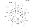
図2に示すように、このエンジン10の各気筒100には、5つのポート101〜105が設けられている。各ポート101〜105には、図示しないが、閉じることにより燃焼室を画成し、開くことにより該燃焼室に流体を導入する開閉弁がそれぞれ設けられている。そして、吸気通路20は、吸気マニホールド27を介して、2つの吸気ポート(第1のポート)101,102に接続し、排気通路30は、排気マニホールド36を介して、2つの排気ポート103,104に接続し、EGR通路40は、専用のマニホールド44を介して、1つのEGRポート(第2のポート)105に接続している。
As shown in FIG. 2, each
図1に戻り、このエンジン10は、以上に加えて、補助吸気通路50と第1の接続通路60と第2の接続通路70と副EGR通路81,82とを有する。補助吸気通路50は、上記エアクリーナ21からEGR通路40に接続し、該EGR通路40への吸気の導入を可能とする。補助吸気通路50は、電動式コンプレッサ42よりも上流側においてEGR通路40に接続している。
Returning to FIG. 1, the
第1接続通路60は、EGR通路40と吸気通路20とを接続し、EGR通路40内を流れる流体の吸気通路20への導入を可能とする。第1接続通路60は、電動式コンプレッサ42とEGR制御弁43との間においてEGR通路40に接続し、また、過給機コンプレッサ23よりも上流側において吸気通路20に接続している。
The
第2接続通路70もまた、EGR通路40と吸気通路20とを接続するが、第1接続通路60よりも下流側にある。すなわち、第2接続通路70は、EGR制御弁43よりも下流側においてEGR通路40に接続し、また、過給機コンプレッサ23よりも下流側において吸気通路20に接続している。
The
副EGR通路81,82は、排気マニホールド36とEGRクーラ41より上流側のEGR通路40とを接続し、かつEGRクーラ41より下流側のEGR通路40と吸気マニホールド27とを接続するもので、排気マニホールド36内の排気の吸気マニホールド27への還流を可能とする。
The
そして、以上の各流体通路20,30,40,50,60,70,81,82に複数のバルブが配設されている。すなわち、吸気通路20には第1接続通路60との接続部の上流側に(符号93)、排気通路30にはEGR通路40との接続部の下流側に(同98)、EGR通路40には排気通路30との接続部の下流側(同99)及び補助吸気通路50との接続部の上流側に(同92)、補助吸気通路50にはEGR通路40との接続部の上流側に(同91)、第1接続通路60にはEGR通路40との接続部の下流側に(同94)、第2接続通路70には吸気通路20との接続部の下流側に(同95)、副EGR通路81にはEGR通路40との接続部の上流側に(同96)、副EGR通路82にはEGR通路40との接続部の下流側に(同97)に、それぞれ流体通路を開閉するバルブが配設されている。
A plurality of valves are disposed in the
ここで、EGR通路40と補助吸気通路50との接続部近傍の2つのバルブ91,92は、電動式コンプレッサ42に上記補助吸気通路50を介して流体を流入させるか又は上記接続部より上流側のEGR通路40を介して流体を流入させるかを切り替える第1の流路調整手段を構成する。また、第1接続通路60と吸気通路20及びEGR通路40との接続部近傍の2つのバルブ93,94は、過給機コンプレッサ23に上記第1接続通路60を介して流体を流入させるか又は上記接続部より上流側の吸気通路20を介して流体を流入させるかを切り替える第2の流路調整手段を構成する。
Here, the two
また、図3に示すように、このエンジン10には、上記の複数の流体通路開閉バルブ91〜99、前述の吸気絞り弁26、ウェイストゲート弁35、電動式コンプレッサ42、及びEGR制御弁43の他、各気筒100の燃焼室に燃料を噴射する燃料噴射弁11等を制御するコントロールユニット200が備えられている。コントロールユニット200には、エンジン回転数Neを検出するエンジン回転センサ201、吸気通路20及び補助吸気通路50を通過する空気流量Qaを計測するエアフローメータ202、電動式コンプレッサ42の直上流部と直下流部におけるEGR通路40内の圧力P1,P2を検出する入力圧センサ203と出力圧センサ204、吸気マニホールド27内の圧力Pinを検出する吸気圧センサ205、EGR通路40の専用マニホールド44内の圧力Pegrを検出するEGRガス圧センサ206、及びアクセルペダル(図示せず)の踏込量Sを検出するアクセル開度センサ207等からの信号が入力される。ここで、上記エンジン回転数Neや空気流量Qa等は、エンジン10の運転状態を代表するパラメータである。
As shown in FIG. 3, the
コントロールユニット200は、図4に示すように、軽負荷時(領域i)のみならず、高負荷時(領域ii)にもEGRを実行する(制御内容は後述する)。高負荷時にEGRを行う利点は、NOx排出量の低減に加えて、およそ次のようなところにある。一般に、高負荷時は、燃焼室内がより高温・高圧になるから、たとえ圧縮工程で燃料を噴射しても、燃料の早期自己着火が起こって異常燃焼が発生し易い。このような事態はパティキュレート(煤)の発生を促進する。ところが、このとき、燃焼室に既燃ガスであるEGRガスを導入すると、噴射した燃料の自己着火遅れを図ることができる。つまり、燃料を噴射してから自己着火するまでの時間をかせぐことができるのである。したがって、高負荷時にもEGRを行うことにより、燃料を早めに噴射することができ、その結果、十分な予混合燃焼が可能となって、パティキュレート(煤)の発生を抑制することができるようになる。もちろん、このような利点は地球環境面において重要であるから、上記領域i,iiのみならず、図4に示すエンジン10の運転領域の全領域でEGRを可能にすることが望まれる。
As shown in FIG. 4, the
また、本実施形態では、コントロールユニット200は、図4に示すように、加速時(矢印及び領域iii)には、EGRを停止し、その結果不用となったEGR用の機器・設備類を有効利用して、加速時に重要なファクタの1つである出力応答性の向上を図る(制御内容は後述する)。
In the present embodiment, as shown in FIG. 4, the
ここで、図5を参照して、本実施形態におけるEGR制御の具体的動作の1例を説明する。図5は、燃焼室へのEGRガスの導入量と圧力比との関係を表している。ここで、圧力比は、電動式コンプレッサ42の直上流部におけるEGR通路40内の入力圧P1に対する直下流部における出力圧P2の比である(P2/P1)。ただし、入力圧P1は、例えば図1に示した本実施形態の構成によれば、大気圧に近似できるから、この図5の特性において、縦軸を、EGR用マニホールド44内のEGRガス圧Pegr、すなわちEGRポート105内の圧力に置き換えることもできる。
Here, an example of a specific operation of the EGR control in the present embodiment will be described with reference to FIG. FIG. 5 shows the relationship between the amount of EGR gas introduced into the combustion chamber and the pressure ratio. Here, the pressure ratio is a ratio of the output pressure P2 in the immediately downstream portion to the input pressure P1 in the
一般に、まずエンジン10の運転状態に応じてEGR率が決定され、該EGR率や吸気量(新気量)等に基づいてEGR量が決定される。ここで、例えばEGR率を60〜70%にするためのEGR量がQegrであったとすると、図5の特性から圧力比がαと決定する。ここで、出力圧P2は、電動式コンプレッサ42のモータの回転数に依存し、該モータの回転数は該モータへの印加電圧の通電時間に依存する。したがって、上記圧力比αが得られるように、入力圧(P1)センサ203や出力圧(P2)センサ204あるいはEGRガス圧(Pegr)センサ206の検出結果を見ながら、電動式コンプレッサ42のモータへの印加電圧の通電をON/OFFする時間を制御(DUTY制御)すればよい。
Generally, the EGR rate is first determined according to the operating state of the
次に、エンジン10の運転状態に基づくEGR制御を、特に、流体の流路の制御を中心に説明する。まず、表1に軽負荷時における各バルブの作動状態を示す。

図1に例示したように、コントロールユニット200は、エンジン10が軽負荷状態であると判定したときは、バルブ93を開、バルブ94を閉とすることにより、第1接続通路60の接続部より上流側の吸気通路20を介して吸気を過給機コンプレッサ23に流入させる。その結果、吸気は、エアクリーナ21から、吸気通路20、上記バルブ93、過給機コンプレッサ23(過給度は小さい)、インタクーラ25、及び吸気絞り弁26等を経て、吸気マニホールド27から各気筒に導入される(流路A)。また、バルブ95が開とされることにより、インタクーラ25を出た吸気は、上記バルブ95、第2接続通路70、及びEGR通路40の1部分を経て、EGR用マニホールド44からも各気筒に導入される(流路B)。
As illustrated in FIG. 1, when the
以上は、表1における制御例1の場合であったが、制御例2のように、併せてバルブ91を開、バルブ92を閉とすることにより、補助吸気通路50を介して吸気を電動式コンプレッサ42に流入させるようにしてもよい。その結果、吸気は、エアクリーナ21から、補助吸気通路50、上記バルブ91、EGR通路40の1部分、電動式コンプレッサ42(過給度は小さい)、及びEGR制御弁43(開、好ましくは表1に示したように全開にする)等を経て、上記流路Bに合流する(流路C)。
The above is the case of the control example 1 in Table 1, but as in the control example 2, the
一方、排気は、バルブ98が開とされることにより、各気筒から、排気マニホールド36、排気通路30、過給機タービン24、排気浄化装置31、及び上記バルブ98等を経て、大気に放出される(流路D)。
On the other hand, the exhaust is released into the atmosphere from each cylinder through the
そして、EGRガスは、バルブ99が閉で、バルブ96,97が開とされることにより、副EGR通路81,82及びEGR通路の1部分を使い、かつEGRクーラ41を経由して、排気マニホールド36から吸気マニホールド27に還流される(流路E)。したがって、EGRガスは、この吸気マニホールド27内で吸気(新気)と遭遇し、混じり合う。
The EGR gas is exhausted by using the
以上により、図2に例示したように、各気筒100の燃焼室には、第1ポート(吸気ポート)101,102からは、吸気(新気)とEGRガスとの既混合流体が導入され、第2ポート(EGRポート)105からは、吸気(新気)のみが導入される。
As described above, as illustrated in FIG. 2, the mixed fluid of the intake air (fresh air) and the EGR gas is introduced into the combustion chamber of each
次に、表2に高負荷時における各バルブの作動状態を示す。
図6に例示したように、コントロールユニット200は、エンジン10が高負荷状態であると判定したときは、軽負荷時と同様、バルブ93を開、バルブ94を閉として、吸気を流路Aにより吸気マニホールド27から各気筒に導入する。ただし、バルブ95が閉とされることにより、流路Bは形成されない。
As illustrated in FIG. 6, when the
一方、EGRガスは、EGR通路40の全長を使って、排気通路30からEGR用マニホールド44に還流される。すなわち、バルブ96,97が閉で、バルブ99が開、及びバルブ91が閉、バルブ92が開とされることにより、補助吸気通路50の接続部より上流側のEGR通路40を介してEGRガスが電動式コンプレッサ42に流入されることになり、その結果、EGRガスは、上記バルブ99から、EGR通路40、EGRクーラ41、上記バルブ92、電動式コンプレッサ42、及びEGR制御弁43(開、好ましくは表2に示したように開度の制御を行う)等を経て、EGR用マニホールド44から各気筒に導入される(流路F)。したがって、EGRガスと吸気(新気)とは、燃焼室に導入されるまで遭遇することがない。
On the other hand, the EGR gas is recirculated from the
以上により、図7に例示したように、各気筒100の燃焼室には、第1ポート(吸気ポート)101,102からは、吸気(新気)のみが導入され、第2ポート(EGRポート)105からは、EGRガスのみが導入される。
As described above, as illustrated in FIG. 7, only the intake air (fresh air) is introduced into the combustion chamber of each
次に、表3に加速時における各バルブの作動状態を示す。
図8に例示したように、コントロールユニット200は、エンジン10が加速状態であると判定したときは、バルブ91を開、バルブ92を閉として、補助吸気通路50を介して吸気を電動式コンプレッサ42に流入させると共に、バルブ93を閉、バルブ94を開として(併せてEGR制御弁43も閉として)、第1接続通路60を介して吸気を過給機コンプレッサ23に流入させる。その結果、吸気は、エアクリーナ21から、補助吸気通路50、上記バルブ91、EGR通路40の1部分、電動式コンプレッサ42(過給度は最大:例えば電動式コンプレッサ42のモータに電圧を最大DUTY比(例えば100%)で印加して電動式コンプレッサ42を最大速度で回転駆動する)、上記バルブ94、第1接続通路60、過給機コンプレッサ23(過給度は大きい)、吸気通路20の1部分、インタクーラ25、及び吸気絞り弁26等を経て、吸気マニホールド27から各気筒に導入される(流路G)。また、バルブ95が開とされることにより、流路Bが形成され、その結果、インタクーラ25を出た吸気は、EGR用マニホールド44からも各気筒に導入される。
As illustrated in FIG. 8, when the
一方、EGRガスは、バルブ99,96,97,92が全て閉とされることにより、排気側から吸気側に還流されることがない。
On the other hand, the EGR gas is not recirculated from the exhaust side to the intake side by closing all the
以上により、図9に例示したように、各気筒100の燃焼室には、第1ポート(吸気ポート)101,102及び第2ポート(EGRポート)105から、吸気(新気)のみが導入される。
As described above, as illustrated in FIG. 9, only intake air (fresh air) is introduced into the combustion chamber of each
本実施形態では、図2、図7、図9から明らかなように、吸気通路20が接続する第1ポート101,102と、EGR通路40が接続する第2ポート105とを独立させたから、吸気通路20内の吸気圧の影響を受けずに、EGRガスを燃焼室に導入することが可能となる。加えて、図1、図6、図8から明らかなように、上記EGR通路40にEGRガスを燃焼室に導入する圧力を制御するコンプレッサ42を設けたから、このコンプレッサ42でEGRガスの圧力を昇圧することにより、エンジン10の運転状態に拘らず、たとえ高負荷時(図4の領域ii)であっても、EGRガスを強制的に第2ポート105を介して燃焼室に導入することが可能となる(図7参照)。
In this embodiment, as is apparent from FIGS. 2, 7, and 9, the
そのうえで、図1、図6、図8から明らかなように、EGR通路40が排気通路30から分岐する分岐部を排気浄化装置31よりも下流側に位置させたから、特に図6に示したように、EGRガスは、相対的に低温で、かつ未燃成分やパティキュレートが除去された排気(既燃ガス)から採取されることになる。これにより、EGR通路40に配設した上記コンプレッサ42はEGRガスに暴露されても、その耐熱性、耐久性、信頼性が図られる。また、EGRガスを燃焼室に導入する量を制御するEGR制御弁43は、EGR通路40上において、上記コンプレッサ42よりもさらに下流側に位置しているから、該EGR制御弁43の耐熱性、耐久性、信頼性も同様に図られる。
In addition, as is clear from FIGS. 1, 6 and 8, the branch portion where the
また、上記コンプレッサ42は電動式であるから、例えば機械式のものを採用した場合に比べて、応答性及び精度に優れるEGRガスの圧力制御(図5に示したような出力圧P2又はEGRガス圧Pegrの制御)が可能となる。
Further, since the
また、過給機22により吸気圧Pinがより一層上昇し、EGR供給がより一層困難な状況になっても、上記コンプレッサ42でEGRガス圧Pegrをそれに対抗して上昇させることにより、EGRガスを燃焼室に導入することが可能となる。
Further, even when the intake pressure Pin is further increased by the
また、エンジン10の運転状態に応じて、第1流路調整手段91,92と、第2流路調整手段93,94(状況によりEGR制御弁43も第2流路調整手段の構成要素となり得る:図8参照)とを制御することにより、吸気通路20とEGR通路40と補助吸気通路50と第1接続通路60とをいろいろに組み合わせて、吸気の燃焼室への流路(A,C,G)と、EGRガスの燃焼室への流路(F)とを柔軟に変更・選択することが可能となり、その結果、エンジン10の運転状態に好ましく適応した吸気及びEGRガスの燃焼室への導入の仕方が実現する。
Further, depending on the operating state of the
また、図6、図7から明らかなように、高負荷時には、吸気とEGRガスとが途中で合流することなく、それぞれ独立の系統で燃焼室に導入されるようになるから、互いの影響を受け合うことなく、良好な精度で、各流体が所定の要求量だけ燃焼室に供給される。 Further, as is clear from FIGS. 6 and 7, when the load is high, the intake air and the EGR gas do not merge in the middle and are introduced into the combustion chamber by independent systems. Without accepting, each fluid is supplied to the combustion chamber by a predetermined required amount with good accuracy.
また、図8、図9から明らかなように、加速時には、EGRガスの燃焼室への導入が停止され、その結果、EGRガスの圧力制御のために設けたコンプレッサ42が不用となる。その場合に、流路Gにより、上記コンプレッサ42を有効利用して、吸気の過給を行うようにしたから、結果的に、吸気が上記コンプレッサ42と本来の過給機コンプレッサ23とにより直列二段に過給されるようになって、加速時に重要なファクタの1つである出力応答性の向上が図られる。
As is apparent from FIGS. 8 and 9, during acceleration, the introduction of EGR gas into the combustion chamber is stopped, and as a result, the
さらに、図8、図9から明らかなように、加速時には、EGRガスの燃焼室への導入が停止され、その結果、EGRガスの燃焼室への独立導入のために設けた第2ポート105が不用となる。その場合に、流路Bにより、上記第2ポート105を利用して吸気の燃焼室への導入を行うようにしたから、結果的に、吸気が上記第2ポート105と本来の第1ポート101,102とにより低抵抗に大量に燃焼室に導入されるようになって、この点においても、加速時に重要なファクタの1つである出力応答性の向上が図られる。なお、この流路Bによる同様の効果は、図1、図2から明らかなように、軽負荷時においても奏される。
Further, as is apparent from FIGS. 8 and 9, during acceleration, the introduction of EGR gas into the combustion chamber is stopped, and as a result, the
以上説明した実施形態は、本発明を実施するための最良の形態ではあるが、特許請求の範囲を逸脱しない限り、なお変更が可能なことはいうまでもない。例えば、図1、図6、図8から明らかなように、第2接続通路70及びバルブ95を省略しても本発明の実現に何等影響を及ぼすものではない。すなわち、図1の軽負荷時及び図8の加速時において、EGR通路40の下流部を吸気通路の1部分として利用しなくても(流路Bを形成しなくても)、吸気通路20により(流路A,Gにより)吸気を各気筒に導入することが可能である。また、図6の高負荷時においては、吸気通路20とEGR通路40とは、互いに独立した流路A,Fを形成するので、第2接続通路70及びバルブ95ははじめからなくてもよい。
The embodiment described above is the best mode for carrying out the present invention, but it goes without saying that the embodiment can still be changed without departing from the scope of the claims. For example, as is apparent from FIGS. 1, 6, and 8, the omission of the
以上のように、本発明によれば、エンジンの運転状態に拘らず、たとえ高負荷時であっても、EGRガスの燃焼室への導入を可能とし、かつ、そのためにEGR通路に備えた圧力制御手段の耐熱性、耐久性、信頼性を図ることができる。本発明は、エンジンのEGR制御装置一般の技術分野において幅広い産業上の利用可能性を有する。 As described above, according to the present invention, it is possible to introduce the EGR gas into the combustion chamber even at a high load regardless of the operating state of the engine, and the pressure provided in the EGR passage for that purpose. The heat resistance, durability and reliability of the control means can be achieved. The present invention has wide industrial applicability in the general technical field of engine EGR control devices.
10 エンジン
20 吸気通路
22 過給機
23 コンプレッサ
24 タービン
30 排気通路
31 排気浄化装置
40 EGR通路
42 電動式コンプレッサ(圧力制御手段)
43 EGR制御弁
50 補助吸気通路
60 第1接続通路
70 第2接続通路
91,92 流体通路開閉バルブ(第1の流路調整手段)
93,94 流体通路開閉バルブ(第2の流路調整手段)
95 流体通路開閉バルブ(開閉弁)
101,102 吸気ポート(第1のポート)
105 EGRポート(第2のポート)
200 コントロールユニット(制御手段)
201 エンジン回転センサ(運転状態検出手段)
202 エアフローメータ(運転状態検出手段)
DESCRIPTION OF
43
93, 94 Fluid passage opening / closing valve (second flow path adjusting means)
95 Fluid passage open / close valve (open / close valve)
101,102 Intake port (first port)
105 EGR port (second port)
200 Control unit (control means)
201 Engine rotation sensor (operating state detection means)
202 Air flow meter (operation state detection means)
Claims (6)
Priority Applications (5)
| Application Number | Priority Date | Filing Date | Title |
|---|---|---|---|
| JP2003270339A JP4207695B2 (en) | 2003-07-02 | 2003-07-02 | EGR control device for engine |
| US10/872,048 US6945236B2 (en) | 2003-07-02 | 2004-06-17 | EGR control apparatus for engine |
| CNA2004100598990A CN1576561A (en) | 2003-07-02 | 2004-06-18 | Egr control apparatus for engine |
| DE602004004947T DE602004004947T2 (en) | 2003-07-02 | 2004-06-23 | EGR control device for internal combustion engines |
| EP04014717A EP1493907B1 (en) | 2003-07-02 | 2004-06-23 | Egr control apparatus for engine |
Applications Claiming Priority (1)
| Application Number | Priority Date | Filing Date | Title |
|---|---|---|---|
| JP2003270339A JP4207695B2 (en) | 2003-07-02 | 2003-07-02 | EGR control device for engine |
Publications (2)
| Publication Number | Publication Date |
|---|---|
| JP2005023900A JP2005023900A (en) | 2005-01-27 |
| JP4207695B2 true JP4207695B2 (en) | 2009-01-14 |
Family
ID=33432375
Family Applications (1)
| Application Number | Title | Priority Date | Filing Date |
|---|---|---|---|
| JP2003270339A Expired - Fee Related JP4207695B2 (en) | 2003-07-02 | 2003-07-02 | EGR control device for engine |
Country Status (5)
| Country | Link |
|---|---|
| US (1) | US6945236B2 (en) |
| EP (1) | EP1493907B1 (en) |
| JP (1) | JP4207695B2 (en) |
| CN (1) | CN1576561A (en) |
| DE (1) | DE602004004947T2 (en) |
Families Citing this family (114)
| Publication number | Priority date | Publication date | Assignee | Title |
|---|---|---|---|---|
| US6988365B2 (en) * | 2003-11-19 | 2006-01-24 | Southwest Research Institute | Dual loop exhaust gas recirculation system for diesel engines and method of operation |
| JP4052242B2 (en) | 2003-12-24 | 2008-02-27 | 日産自動車株式会社 | Exhaust gas recirculation device for internal combustion engine |
| JP4534514B2 (en) * | 2004-02-18 | 2010-09-01 | 株式会社デンソー | Diesel engine control device |
| ATE333584T1 (en) * | 2004-04-21 | 2006-08-15 | Fiat Ricerche | TURBOCHARGED DIESEL ENGINE WITH LONG-PATH EXHAUST GAS RECIRCULATION SYSTEM |
| EP1771647A1 (en) * | 2004-07-23 | 2007-04-11 | Honeywell International, Inc. | Use of compressor to turbine bypass for electric boosting system |
| DE102004044893A1 (en) * | 2004-09-14 | 2006-03-30 | Volkswagen Ag | Exhaust gas recirculation device and method for operating an exhaust gas recirculation device |
| DE102004055846B4 (en) * | 2004-11-19 | 2016-12-15 | Bayerische Motoren Werke Aktiengesellschaft | Vehicle with turbo diesel engine and exhaust gas recirculation |
| JP2008527248A (en) * | 2005-01-18 | 2008-07-24 | バイエリッシェ モートーレン ウエルケ アクチエンゲゼルシャフト | Vehicle with exhaust recirculation system |
| JP2008530423A (en) * | 2005-02-07 | 2008-08-07 | ボーグワーナー・インコーポレーテッド | Exhaust throttle EGR valve module for diesel engine |
| DE102005012644A1 (en) * | 2005-03-18 | 2006-09-21 | Siemens Ag | Method for returning a partial flow of exhaust gas to an internal combustion engine of a motor vehicle |
| US7137381B1 (en) * | 2005-04-13 | 2006-11-21 | Ricardo, Inc. | Indirect variable valve actuation for an internal combustion engine |
| US7168250B2 (en) * | 2005-04-21 | 2007-01-30 | International Engine Intellectual Property Company, Llc | Engine valve system and method |
| DE102005026503A1 (en) * | 2005-06-09 | 2006-12-14 | Robert Bosch Gmbh | Method and device for controlling an internal combustion engine |
| FR2886887B1 (en) * | 2005-06-09 | 2007-09-14 | Renault Sas | ADDITIONAL HEATING DEVICE OF A MOTOR VEHICLE |
| US20070068141A1 (en) * | 2005-06-15 | 2007-03-29 | Opris Cornelius N | Exhaust treatment system |
| US7107764B1 (en) * | 2005-06-15 | 2006-09-19 | Caterpillar Inc. | Exhaust treatment system |
| AU2005334251B2 (en) * | 2005-07-11 | 2012-04-19 | Mack Trucks, Inc. | Engine and method of maintaining engine exhaust temperature |
| FR2892155B1 (en) * | 2005-10-19 | 2007-12-14 | Inst Francais Du Petrole | CIRCUIT FOR SUPPLYING AT LEAST ONE FLUID OF A SUPERCHARGED MOTOR AND METHOD FOR FEEDING AT AT LEAST ONE FLUID SUCH A MOTOR |
| FR2892770B1 (en) * | 2005-10-28 | 2008-01-18 | Renault Sas | CONTROLLED RECIRCULATION DEVICE FOR BURNED GASES OF A HIGH PRESSURE EGR CIRCUIT |
| FR2895027A1 (en) * | 2005-12-20 | 2007-06-22 | Renault Sas | Internal combustion engine e.g. turbocharged spark ignition internal combustion engine, has blow line opening directly or indirectly in cylinders, upstream of their connection with exhaust line to inject compressed delivery air in cylinders |
| DE102005062255B4 (en) * | 2005-12-24 | 2010-02-18 | Markus Schmidt | Internal combustion engine with internal combustion |
| US7762060B2 (en) * | 2006-04-28 | 2010-07-27 | Caterpillar Inc. | Exhaust treatment system |
| US7267114B1 (en) | 2006-05-03 | 2007-09-11 | Lemur Group L.L.C. | Wildland fire vehicle escape system |
| EP1870590A1 (en) * | 2006-06-22 | 2007-12-26 | C.R.F. Società Consortile per Azioni | Internal combustion engine with a pump for exhaust gas recirculation |
| JP4611941B2 (en) * | 2006-06-29 | 2011-01-12 | トヨタ自動車株式会社 | Exhaust gas recirculation device for internal combustion engine |
| DE102006043426A1 (en) * | 2006-09-15 | 2008-03-27 | Volkswagen Ag | Internal-combustion engine i.e. diesel engine, has exhaust gas return line connected with exhaust gas line to turbine, and charge-cycle valve separated from inlet channel and outlet channel and connected with exhaust gas return line |
| US20080078170A1 (en) * | 2006-09-29 | 2008-04-03 | Gehrke Christopher R | Managing temperature in an exhaust treatment system |
| JP4333725B2 (en) * | 2006-10-25 | 2009-09-16 | トヨタ自動車株式会社 | Exhaust gas recirculation device for internal combustion engine |
| EP2096295B1 (en) * | 2006-12-11 | 2011-03-09 | Borgwarner Emission Systems Spain, S.L. | Internal combustion engine egr apparatus |
| FR2910934B1 (en) * | 2006-12-27 | 2009-01-30 | Renault Sas | ESTIMATION METHOD AND SYSTEM FOR MONITORING THE EGR RATE ON A MOTOR SUPERCURRENT BY A TURBOCHARGER AND EQUIPPED WITH TWO ADMISSION COLLECTORS AND A SWIRL COMPONENT. |
| JP4858278B2 (en) * | 2007-04-06 | 2012-01-18 | トヨタ自動車株式会社 | Exhaust gas recirculation device for internal combustion engine |
| FR2914698A3 (en) * | 2007-04-06 | 2008-10-10 | Renault Sas | Exhaust gas recirculation device for e.g. oil engine, has by-pass duct with valve arranged downstream of heat exchanger, relative to circulation directions of exhaust gases in duct, that includes another valve arranged upstream of exchanger |
| US7743757B2 (en) * | 2007-07-19 | 2010-06-29 | Ford Global Technologies, Llc | System and method for exhaust gas recirculation |
| JP4561817B2 (en) * | 2007-12-04 | 2010-10-13 | トヨタ自動車株式会社 | Internal combustion engine |
| DE102007060142B4 (en) * | 2007-12-13 | 2010-09-09 | Ford Global Technologies, LLC, Dearborn | Control method for increasing the exhaust gas temperature over time |
| US8572944B2 (en) | 2007-12-19 | 2013-11-05 | General Electric Company | Prime mover for an exhaust gas recirculation system |
| CN101970845B (en) * | 2008-02-08 | 2013-12-18 | 卡明斯公司 | Apparatus, system, and method utilizing exhaust gas recirculation |
| FR2927373B1 (en) * | 2008-02-12 | 2015-07-31 | Renault Sas | DOUBLE RECIRCULATION LOOP ADMISSION DEVICE |
| DE102008060698A1 (en) * | 2008-02-22 | 2009-08-27 | Behr Gmbh & Co. Kg | Rotary valve and heat pump |
| US7963275B2 (en) * | 2008-07-09 | 2011-06-21 | Ford Global Technologies, Llc | System and method for improving exhaust gas recirculation for a turbocharged engine |
| DE102008035553B4 (en) * | 2008-07-30 | 2017-06-08 | Bayerische Motoren Werke Aktiengesellschaft | Internal combustion engine with an exhaust gas recirculation device |
| US8474258B2 (en) * | 2008-09-24 | 2013-07-02 | Deere & Company | Stoichiometric compression ignition engine with increased power output |
| US8250865B2 (en) * | 2008-11-05 | 2012-08-28 | Ford Global Technologies, Llc | Using compressed intake air to clean engine exhaust gas recirculation cooler |
| JP2010121469A (en) * | 2008-11-17 | 2010-06-03 | Toyota Motor Corp | Exhaust emission control device |
| US20100146967A1 (en) * | 2008-12-12 | 2010-06-17 | Alexander Simpson | Emission system, apparatus, and method |
| US20100146968A1 (en) * | 2008-12-12 | 2010-06-17 | Alexander Simpson | Emission system, apparatus, and method |
| ATE552417T1 (en) * | 2009-02-16 | 2012-04-15 | Caterpillar Motoren Gmbh & Co | TURBOCHARGED ENGINE WITH EXHAUST GAS RECYCLING |
| US20110036335A1 (en) * | 2009-08-12 | 2011-02-17 | International Engine Intellectual Property Company Llc. | Hybrid intake system for superatmospheric charging of an engine intake manifold using lowpressure egr/fresh air blending |
| US20110094224A1 (en) * | 2009-10-28 | 2011-04-28 | Sheidler Alan D | Metering exhaust gas recirculation system for a turbocharged engine having a turbogenerator system |
| US8522756B2 (en) * | 2009-10-28 | 2013-09-03 | Deere & Company | Interstage exhaust gas recirculation system for a dual turbocharged engine having a turbogenerator system |
| US8522757B2 (en) * | 2009-10-28 | 2013-09-03 | Deere & Company | Metering exhaust gas recirculation system for a dual turbocharged engine having a turbogenerator system |
| US8056339B2 (en) * | 2010-01-08 | 2011-11-15 | Ford Global Technologies, Llc | Warming intake air using EGR cooler in dual-throttle boosted engine system |
| US8353275B2 (en) * | 2010-01-08 | 2013-01-15 | Ford Global Technologies, Llc | Dual throttle for improved tip-out stability in boosted engine system |
| US8001779B2 (en) * | 2010-03-24 | 2011-08-23 | Ford Global Technologies, Llc | Hybrid high-pressure low-pressure EGR system |
| GB2480240A (en) * | 2010-05-10 | 2011-11-16 | Gm Global Tech Operations Inc | Turbocharged diesel engine with long-route EGR and an auxiliary intake compressor |
| DE102010023524A1 (en) * | 2010-06-11 | 2011-12-15 | Audi Ag | Motor vehicle and method for operating an internal combustion engine |
| US8439021B2 (en) * | 2010-06-15 | 2013-05-14 | Deere & Company | EGR system for an internal combustion engine |
| DE102010036946A1 (en) | 2010-08-11 | 2012-02-16 | Ford Global Technologies, Llc. | High pressure exhaust gas recirculation system with heat recovery |
| US8479511B2 (en) | 2010-09-09 | 2013-07-09 | Ford Global Technologies, Llc | Method and system for a turbocharged engine |
| US8701409B2 (en) | 2010-09-09 | 2014-04-22 | Ford Global Technologies, Llc | Method and system for a turbocharged engine |
| US8069663B2 (en) | 2010-09-09 | 2011-12-06 | Ford Global Technologies, Llc | Method and system for turbocharging an engine |
| KR101753402B1 (en) * | 2011-01-24 | 2017-07-03 | 두산인프라코어 주식회사 | an Exhaust Gas Recirculation Apparatus Control method for a Construction Heavy Equipment |
| US20130319382A1 (en) * | 2011-02-08 | 2013-12-05 | Toyota Jidosha Kabushiki Kaisha | Exhaust gas recirculation apparatus of internal combustion engine |
| US8443603B2 (en) * | 2011-05-10 | 2013-05-21 | GM Global Technology Operations LLC | Intake manifold assembly for dedicated exhaust gas recirculation |
| DE102011077147A1 (en) | 2011-06-07 | 2012-12-13 | Abb Turbo Systems Ag | Exhaust duct system of internal combustion engine, has valves for switching on and off return lines provided from exhaust gas receiver to air receiver and from turbine to air receiver |
| RU2607147C2 (en) * | 2011-07-13 | 2017-01-10 | ФОРД ГЛОУБАЛ ТЕКНОЛОДЖИЗ, ЭлЭлСи | Method of engine actuation (versions) and engine system |
| US9181905B2 (en) * | 2011-09-25 | 2015-11-10 | Cummins Inc. | System for controlling an air handling system including an electric pump-assisted exhaust gas recirculation |
| DE102012005225A1 (en) * | 2012-03-15 | 2013-09-19 | Volkswagen Aktiengesellschaft | Device for additional compression of the charge air of an internal combustion engine |
| US8844269B2 (en) | 2012-03-16 | 2014-09-30 | Cummins Inc. | Aftertreatment system and method for pre-decomposed reductant solution |
| FR2991725B1 (en) * | 2012-06-11 | 2017-12-15 | Valeo Systemes De Controle Moteur | ASSEMBLY COMPRISING A THERMAL MOTOR AND AN ELECTRIC COMPRESSOR |
| US9027343B2 (en) * | 2012-06-14 | 2015-05-12 | Ford Global Technologies, Llc | Approach for supplying vacuum via a supercharger |
| US9964056B2 (en) | 2012-10-19 | 2018-05-08 | General Electric Company | System and method for controlling exhaust emissions and specific fuel consumption of an engine |
| US9140179B2 (en) * | 2012-10-19 | 2015-09-22 | General Electric Company | System and method for controlling exhaust emissions and specific fuel consumption of an engine |
| JP2014098324A (en) * | 2012-11-13 | 2014-05-29 | Hks Co Ltd | Supercharger for engine |
| US9032940B2 (en) | 2013-01-18 | 2015-05-19 | Cummins Inc. | Systems and methods for dedicated exhaust gas recirculation and control |
| US9255550B2 (en) * | 2013-03-08 | 2016-02-09 | GM Global Technology Operations LLC | Emission system and method of selectively directing exhaust gas and air within an internal combustion engine |
| AT514054B1 (en) * | 2013-03-13 | 2015-01-15 | Avl List Gmbh | Internal combustion engine with several cylinders |
| AT512890B1 (en) * | 2013-03-13 | 2013-12-15 | Avl List Gmbh | Internal combustion engine |
| US9200599B2 (en) * | 2013-04-15 | 2015-12-01 | Southwest Research Institute | Internal combustion engine having dual EGR loops (dedicated EGR loop and low pressure EGR loop) and dual cylinder intake ports |
| JP6001498B2 (en) * | 2013-05-14 | 2016-10-05 | 株式会社日本自動車部品総合研究所 | Intake device for internal combustion engine |
| WO2014199192A1 (en) * | 2013-06-11 | 2014-12-18 | Renault Trucks | Process for operating an internal combustion engine arrangement, and arrangement adapted therefore |
| US9249761B2 (en) | 2013-06-13 | 2016-02-02 | Cummins Inc. | Exhaust gas recirculation and control with twin scroll turbines |
| EP3008308B1 (en) | 2013-06-13 | 2019-05-01 | Dayco IP Holdings, LLC | Pneumatic compressor recirculation valve system |
| US9133852B2 (en) | 2013-06-13 | 2015-09-15 | Dayco Ip Holdings, Llc | Pneumatic compressor recirculation valve system for minimizing surge under boost during throttle closing |
| US20150040559A1 (en) * | 2013-08-07 | 2015-02-12 | Denso International America, Inc. | Intake cooler for intake-exhaust gas handling system |
| DE102013216229A1 (en) * | 2013-08-15 | 2015-02-19 | Volkswagen Aktiengesellschaft | Internal combustion engine with a plurality of cylinders and method for operating an internal combustion engine having a plurality of cylinders |
| US9518519B2 (en) | 2013-11-04 | 2016-12-13 | Cummins Inc. | Transient control of exhaust gas recirculation systems through mixer control valves |
| FR3015578B1 (en) * | 2013-12-19 | 2016-01-29 | Valeo Sys Controle Moteur Sas | AIR INTAKE SYSTEM FOR THERMAL ENGINE |
| US10190509B2 (en) | 2013-12-23 | 2019-01-29 | Ge Global Sourcing Llc | System and method for controlling a dual fuel engine |
| FR3016192B1 (en) * | 2014-01-06 | 2016-02-05 | Peugeot Citroen Automobiles Sa | INTERNAL COMBUSTION ENGINE WITH RECIRCULATION OF EXHAUST GASES |
| US9534542B2 (en) * | 2014-08-07 | 2017-01-03 | Ford Global Technologies, Llc | Systems and methods for EGR control |
| JP6015724B2 (en) * | 2014-09-02 | 2016-10-26 | トヨタ自動車株式会社 | Internal combustion engine system |
| CN104533584B (en) * | 2014-10-30 | 2017-10-20 | 长城汽车股份有限公司 | engine intake and exhaust system and vehicle |
| US10094337B2 (en) | 2015-03-10 | 2018-10-09 | Fca Us Llc | Dual path cooled exhaust gas recirculation for turbocharged gasoline engines |
| US9726121B2 (en) | 2015-03-31 | 2017-08-08 | Electro-Motive Diesel, Inc. | Engine system having reduced pressure EGR system |
| US9664148B2 (en) | 2015-03-31 | 2017-05-30 | Electro-Motive Diesel, Inc. | Engine system having increased pressure EGR system |
| US9989020B2 (en) | 2015-05-15 | 2018-06-05 | Ford Global Technologies, Llc | Auto-ignition internal combustion engine with exhaust-gas turbocharging and exhaust-gas recirculation |
| DE102015208957A1 (en) * | 2015-05-15 | 2016-11-17 | Ford Global Technologies, Llc | Self-igniting internal combustion engine with turbocharging and exhaust gas recirculation |
| DE102016200566A1 (en) * | 2016-01-18 | 2017-07-20 | Mahle International Gmbh | Engine system |
| US9932939B2 (en) | 2016-02-15 | 2018-04-03 | Denso International America, Inc. | Dedicated exhaust gas recirculation system |
| DE102016214083A1 (en) * | 2016-07-29 | 2018-02-01 | Mahle International Gmbh | An internal combustion engine and method for reducing accumulation of a critical amount of condensate in a charge air cooler |
| JP6579085B2 (en) * | 2016-11-15 | 2019-09-25 | 株式会社豊田自動織機 | Electric turbocharger |
| DE102016223222A1 (en) * | 2016-11-23 | 2018-05-24 | Volkswagen Aktiengesellschaft | A spark-ignition internal combustion engine, and method for operating a spark-ignition internal combustion engine |
| FR3059724B1 (en) * | 2016-12-01 | 2018-12-07 | Peugeot Citroen Automobiles Sa | MOTOR CYLINDER HEAD WITH OPTIONAL GAS RECIRCULATION AT HIGH AND LOW PRESSURE |
| DE202016007924U1 (en) | 2016-12-15 | 2017-02-01 | Dieter Finster | Pressure shoe with air circulation |
| US10012159B1 (en) * | 2016-12-16 | 2018-07-03 | Ford Global Technologies, Llc | Systems and methods for a split exhaust engine system |
| JP6698513B2 (en) * | 2016-12-21 | 2020-05-27 | 愛三工業株式会社 | Engine system and intake manifold used therefor |
| FR3064676A1 (en) * | 2017-04-04 | 2018-10-05 | Peugeot Citroen Automobiles Sa | COMPRESSION AIR INJECTION INTERNAL COMBUSTION ENGINE |
| JP6844556B2 (en) * | 2018-02-09 | 2021-03-17 | トヨタ自動車株式会社 | Exhaust purification device for internal combustion engine |
| US11499511B2 (en) * | 2018-08-23 | 2022-11-15 | Volvo Truck Corporation | Method for controlling an internal combustion engine system |
| RU2691237C1 (en) * | 2018-08-27 | 2019-06-11 | Федеральное государственное унитарное предприятие "Центральный ордена Трудового Красного Знамени научно-исследовательский автомобильный и автомоторный институт "НАМИ" (ФГУП "НАМИ") | Double-circuit gas recirculation system of an internal combustion engine with gas turbine supercharging |
| FR3086349B1 (en) * | 2018-09-20 | 2020-12-11 | Renault Sas | INTERNAL COMBUSTION ENGINE AND METHOD OF CONTROL OF AN INTERNAL COMBUSTION ENGINE EQUIPPING A MOTOR VEHICLE |
| KR20200068977A (en) * | 2018-12-06 | 2020-06-16 | 현대자동차주식회사 | Egr cooler |
| EP3981979A1 (en) * | 2020-10-07 | 2022-04-13 | Volvo Truck Corporation | An internal combustion engine system |
Family Cites Families (19)
| Publication number | Priority date | Publication date | Assignee | Title |
|---|---|---|---|---|
| US4231225A (en) * | 1979-02-05 | 1980-11-04 | Aya Kazim K | Turbocharged engine with pressurized gas recirculation |
| US5329912A (en) | 1991-12-19 | 1994-07-19 | Yamaha Hatsudoki Kabushiki Kaisha | Induction system for an internal combustion engine |
| DK170218B1 (en) * | 1993-06-04 | 1995-06-26 | Man B & W Diesel Gmbh | Large pressurized diesel engine |
| SE506130C2 (en) * | 1994-12-08 | 1997-11-10 | Scania Cv Ab | Arrangements for redirecting exhaust gases in supercharged engines with serial turbines |
| GB2305969A (en) | 1995-10-06 | 1997-04-23 | Ford Motor Co | Stratified charge engine |
| US5937650A (en) * | 1997-03-03 | 1999-08-17 | Alliedsignal Inc. | Exhaust gas recirculation system employing a turbocharger incorporating an integral pump, a control valve and a mixer |
| US6041602A (en) * | 1997-06-09 | 2000-03-28 | Southwest Research Institute | Hydraulically-actuated exhaust gas recirculation system and turbocharger for engines |
| US5771868A (en) * | 1997-07-03 | 1998-06-30 | Turbodyne Systems, Inc. | Turbocharging systems for internal combustion engines |
| US5806308A (en) * | 1997-07-07 | 1998-09-15 | Southwest Research Institute | Exhaust gas recirculation system for simultaneously reducing NOx and particulate matter |
| JP3674254B2 (en) | 1997-08-21 | 2005-07-20 | いすゞ自動車株式会社 | EGR device for supercharged engine |
| US6138649A (en) | 1997-09-22 | 2000-10-31 | Southwest Research Institute | Fast acting exhaust gas recirculation system |
| DE19849914C1 (en) * | 1998-10-29 | 1999-11-04 | Daimler Chrysler Ag | Internal combustion engine with auxiliary inlet valve |
| JP2000329009A (en) | 1999-05-17 | 2000-11-28 | Isuzu Ceramics Res Inst Co Ltd | Diesel engine equipped with egr device |
| JP3998861B2 (en) * | 1999-06-16 | 2007-10-31 | 株式会社小松製作所 | Exhaust gas recirculation device and control method thereof |
| US6351946B1 (en) * | 1999-09-27 | 2002-03-05 | Caterpillar Inc. | Exhaust gas recirculation system in an internal combustion engine |
| US6470866B2 (en) * | 2000-01-05 | 2002-10-29 | Siemens Canada Limited | Diesel engine exhaust gas recirculation (EGR) system and method |
| US6386154B1 (en) * | 2000-06-12 | 2002-05-14 | The United States Of America As Represented By The Administrator Of The Environmental Protection Agency | Pumped EGR system |
| US6553959B2 (en) * | 2000-06-13 | 2003-04-29 | Visteon Global Technologies, Inc. | Electronic flow control for a stratified EGR system |
| JP2002276405A (en) | 2001-03-19 | 2002-09-25 | Isuzu Motors Ltd | Exhaust emission control device of diesel engine |
-
2003
- 2003-07-02 JP JP2003270339A patent/JP4207695B2/en not_active Expired - Fee Related
-
2004
- 2004-06-17 US US10/872,048 patent/US6945236B2/en not_active Expired - Fee Related
- 2004-06-18 CN CNA2004100598990A patent/CN1576561A/en active Pending
- 2004-06-23 DE DE602004004947T patent/DE602004004947T2/en not_active Expired - Fee Related
- 2004-06-23 EP EP04014717A patent/EP1493907B1/en not_active Expired - Fee Related
Also Published As
| Publication number | Publication date |
|---|---|
| EP1493907A3 (en) | 2005-05-11 |
| EP1493907B1 (en) | 2007-02-28 |
| US6945236B2 (en) | 2005-09-20 |
| EP1493907A2 (en) | 2005-01-05 |
| US20050000497A1 (en) | 2005-01-06 |
| CN1576561A (en) | 2005-02-09 |
| JP2005023900A (en) | 2005-01-27 |
| DE602004004947D1 (en) | 2007-04-12 |
| DE602004004947T2 (en) | 2007-11-15 |
Similar Documents
| Publication | Publication Date | Title |
|---|---|---|
| JP4207695B2 (en) | EGR control device for engine | |
| US9726090B2 (en) | Engine having low pressure EGR system and control method thereof | |
| JP4544803B2 (en) | Low emission diesel cycle engine | |
| JP5187123B2 (en) | Control device for internal combustion engine | |
| WO2007066833A1 (en) | Exhaust gas purification system for internal combustion engine | |
| US20060124116A1 (en) | Clean gas injector | |
| US20050235644A1 (en) | Turbo-charged diesel engine with a "long route" exhaust-gas recirculation system | |
| WO2011117970A1 (en) | Internal combustion engine with exhaust gas recirculation device | |
| JP4635986B2 (en) | Exhaust gas recirculation device for internal combustion engine | |
| JP4736969B2 (en) | Diesel engine control device | |
| JP5679185B2 (en) | Control device for internal combustion engine | |
| JP2010180818A (en) | Exhaust recirculating device for internal combustion engine | |
| JP2009085094A (en) | Exhaust gas recirculation device for engine | |
| JP6613882B2 (en) | Engine control device | |
| JP5812711B2 (en) | Internal combustion engine | |
| JP2010116894A (en) | Control device of internal combustion engine | |
| JP3743232B2 (en) | White smoke emission suppression device for internal combustion engine | |
| JP2008038825A (en) | Internal combustion engine control device | |
| JPH0791326A (en) | Exhaust gas refluxing device for engine having supercharger | |
| JP3371324B2 (en) | Exhaust gas recirculation device | |
| WO2011005560A2 (en) | Engine breathing system, components and method thereof | |
| JP2014101812A (en) | Exhaust recirculation device of engine | |
| JP2018184873A (en) | Control device for engine | |
| JP2018184870A (en) | Control device for engine | |
| JP2012163009A (en) | Control device for internal combustion engine |
Legal Events
| Date | Code | Title | Description |
|---|---|---|---|
| A621 | Written request for application examination |
Free format text: JAPANESE INTERMEDIATE CODE: A621 Effective date: 20060105 |
|
| A977 | Report on retrieval |
Free format text: JAPANESE INTERMEDIATE CODE: A971007 Effective date: 20080428 |
|
| A131 | Notification of reasons for refusal |
Free format text: JAPANESE INTERMEDIATE CODE: A131 Effective date: 20080520 |
|
| A521 | Request for written amendment filed |
Free format text: JAPANESE INTERMEDIATE CODE: A523 Effective date: 20080714 |
|
| TRDD | Decision of grant or rejection written | ||
| A01 | Written decision to grant a patent or to grant a registration (utility model) |
Free format text: JAPANESE INTERMEDIATE CODE: A01 Effective date: 20080930 |
|
| A01 | Written decision to grant a patent or to grant a registration (utility model) |
Free format text: JAPANESE INTERMEDIATE CODE: A01 |
|
| A61 | First payment of annual fees (during grant procedure) |
Free format text: JAPANESE INTERMEDIATE CODE: A61 Effective date: 20081013 |
|
| R150 | Certificate of patent or registration of utility model |
Free format text: JAPANESE INTERMEDIATE CODE: R150 |
|
| FPAY | Renewal fee payment (event date is renewal date of database) |
Free format text: PAYMENT UNTIL: 20111031 Year of fee payment: 3 |
|
| FPAY | Renewal fee payment (event date is renewal date of database) |
Free format text: PAYMENT UNTIL: 20111031 Year of fee payment: 3 |
|
| FPAY | Renewal fee payment (event date is renewal date of database) |
Free format text: PAYMENT UNTIL: 20121031 Year of fee payment: 4 |
|
| FPAY | Renewal fee payment (event date is renewal date of database) |
Free format text: PAYMENT UNTIL: 20131031 Year of fee payment: 5 |
|
| LAPS | Cancellation because of no payment of annual fees |