JP4205306B2 - Technique for anastomosing using bioadhesive without stitching and apparatus therefor - Google Patents
Technique for anastomosing using bioadhesive without stitching and apparatus therefor Download PDFInfo
- Publication number
- JP4205306B2 JP4205306B2 JP2000513506A JP2000513506A JP4205306B2 JP 4205306 B2 JP4205306 B2 JP 4205306B2 JP 2000513506 A JP2000513506 A JP 2000513506A JP 2000513506 A JP2000513506 A JP 2000513506A JP 4205306 B2 JP4205306 B2 JP 4205306B2
- Authority
- JP
- Japan
- Prior art keywords
- elongated
- distal end
- balloon
- proximal
- distal
- Prior art date
- Legal status (The legal status is an assumption and is not a legal conclusion. Google has not performed a legal analysis and makes no representation as to the accuracy of the status listed.)
- Expired - Fee Related
Links
Images


Classifications
-
- A—HUMAN NECESSITIES
- A61—MEDICAL OR VETERINARY SCIENCE; HYGIENE
- A61B—DIAGNOSIS; SURGERY; IDENTIFICATION
- A61B17/00—Surgical instruments, devices or methods, e.g. tourniquets
- A61B17/11—Surgical instruments, devices or methods, e.g. tourniquets for performing anastomosis; Buttons for anastomosis
-
- A—HUMAN NECESSITIES
- A61—MEDICAL OR VETERINARY SCIENCE; HYGIENE
- A61B—DIAGNOSIS; SURGERY; IDENTIFICATION
- A61B17/00—Surgical instruments, devices or methods, e.g. tourniquets
- A61B17/00491—Surgical glue applicators
-
- A—HUMAN NECESSITIES
- A61—MEDICAL OR VETERINARY SCIENCE; HYGIENE
- A61B—DIAGNOSIS; SURGERY; IDENTIFICATION
- A61B17/00—Surgical instruments, devices or methods, e.g. tourniquets
- A61B2017/00535—Surgical instruments, devices or methods, e.g. tourniquets pneumatically or hydraulically operated
- A61B2017/00557—Surgical instruments, devices or methods, e.g. tourniquets pneumatically or hydraulically operated inflatable
-
- A—HUMAN NECESSITIES
- A61—MEDICAL OR VETERINARY SCIENCE; HYGIENE
- A61B—DIAGNOSIS; SURGERY; IDENTIFICATION
- A61B17/00—Surgical instruments, devices or methods, e.g. tourniquets
- A61B2017/00681—Aspects not otherwise provided for
- A61B2017/00725—Calibration or performance testing
-
- A—HUMAN NECESSITIES
- A61—MEDICAL OR VETERINARY SCIENCE; HYGIENE
- A61B—DIAGNOSIS; SURGERY; IDENTIFICATION
- A61B17/00—Surgical instruments, devices or methods, e.g. tourniquets
- A61B17/11—Surgical instruments, devices or methods, e.g. tourniquets for performing anastomosis; Buttons for anastomosis
- A61B2017/1107—Surgical instruments, devices or methods, e.g. tourniquets for performing anastomosis; Buttons for anastomosis for blood vessels
-
- A—HUMAN NECESSITIES
- A61—MEDICAL OR VETERINARY SCIENCE; HYGIENE
- A61B—DIAGNOSIS; SURGERY; IDENTIFICATION
- A61B17/00—Surgical instruments, devices or methods, e.g. tourniquets
- A61B17/11—Surgical instruments, devices or methods, e.g. tourniquets for performing anastomosis; Buttons for anastomosis
- A61B2017/1139—Side-to-side connections, e.g. shunt or X-connections
Landscapes
- Health & Medical Sciences (AREA)
- Life Sciences & Earth Sciences (AREA)
- Surgery (AREA)
- Heart & Thoracic Surgery (AREA)
- Engineering & Computer Science (AREA)
- Biomedical Technology (AREA)
- Nuclear Medicine, Radiotherapy & Molecular Imaging (AREA)
- Medical Informatics (AREA)
- Molecular Biology (AREA)
- Animal Behavior & Ethology (AREA)
- General Health & Medical Sciences (AREA)
- Public Health (AREA)
- Veterinary Medicine (AREA)
- Surgical Instruments (AREA)
- Materials For Medical Uses (AREA)
Abstract
Description
【0001】
背景技術
外傷の治療及び多くの病気の経過治療の一部として、体の幾つかの部分又は器官に対し血液の流れを再び形成するために血管を接合することがしばしば必要とされる。そのように血管を接合することは血管吻合と呼ばれる。従来、血管吻合部位を閉じる主な方法は手で行う縫合であった。この方法は、多くの外科的専門分野及び外科的処置において選択肢として残っている。多くの外科的処置では、十分な時間が存在し、外科手術部位は手で縫合して血管を吻合するのに適している。例えば多くの心臓バイパス手術において従来使用されてきた麻酔薬を摂取する外科的アプローチでは、血管吻合に必要とされる縫合を手で行うために、アクセスして部位を固定することが必要となっていた。
【0002】
従来の冠状動脈バイパス手術では、患者の胸骨が分割されて引っ込められ、胸の中が開かれる。標準的な冠状動脈バイパス手術のアプローチは出過ぎているため、病気及び死亡を回避するためにコストが嵩んでしまう。出過ぎていない外科手術方法にすることにより、治癒時間が短くなり、痛みも少なくなり、手術後の合併症も少なくなるであろう。
【0003】
近年、心臓バイパス手術が出過ぎていない外科手術に移行している。幾つかの内視鏡心臓手術の記述があるが、内視鏡心臓バイパス手術は可能になっていなかった。内視鏡心臓バイパス手術には血管吻合に関して少なくとも二つの主要な技術的な問題点がある。まず第一に、外科手術において露出させること及び手による操作を行うことが、縫合を手で行うことまでもを考慮していない。第二に、血管内の血液が動いているときに鼓動している心臓に隣接する血管の吻合を行わなければならない。それゆえ、内視鏡心臓バイパス手術中に血管吻合を行うためには、少なくとも一つの血管内の血液が動いているときに手で縫合することなく血管を吻合する方法が必要になる。現段階において、例えば腹腔鏡又は内視鏡のためのウインドーのような小さい外科手術ウインドーを通して血管を吻合する適切な血管吻合技術は、少なくとも一つの血管内の血液が動いているか手術領域の器官が動いている状況下では存在していない。
【0004】
外科手術で露出されるのが限られており、血管内の血液が動いているという制限的な事項を除いても、縫合を手で行うことは、時間がかかってしまうという問題点を更に有する。それゆえ、縫合を手で行う場合のような強度及び信頼性がありつつ迅速に行うことが可能な血管吻合方法が常に求められていた。時間のかからない吻合技術により手術時間は短くなり、その結果、特には長くかかった外科手術処置に伴う患者の病気及び死亡が減少するであろう。本発明は、血管を迅速に吻合する方法を提供することによりこの問題点を解決する。
【0005】
発明の開示
本発明は、並置された一つ以上の中空の体器官の開口を並置することによりそれらの体器官を接合し、それらの体器官の間を血液又は他の物質が移動可能なようにそれらの体器官を接合するのに十分な量の生物接着剤を付する方法に関する。本発明で使用される生物接着剤は、毒性がなく迅速に固まる架橋蛋白質材料である。この方法は、器官を側面同士、端面と側面とで、あるいは端面同士接合するのに適用可能であり、好適には血管、リンパ管又は腸路器官に使用される。この方法は、鼓動している心臓の動脈で手術が行われているときのような、器官の一つが動いている状況下での手術に特に有益である。
【0006】
本発明の更なる実施形態において、この方法は、二つの血管を側面同士接合するのに使用されるとき、第一の管腔から第二の管腔内にそれらの開口を通してガイドワイヤを延ばす工程と、各管腔内にバルーンを位置決めするためにガイドワイヤに沿ってダブルバルーンカテーテルを送る工程と、血管が移動しないようにして開口を並置して維持するためにバルーンを膨張させる工程とを更に含む。この方法は、左冠状動脈の枝に対し内胸動脈を接合しつつ心臓の鼓動中に内視鏡心臓バイパス手術を行うのに好適である。
【0007】
本発明は更に、生物接着剤を付するために二つの中空の体器官の開口を並置して維持するダブルバルーンカテーテルに関する。特には本発明は、第一長手管腔と環状の膨張可能な近位バルーンと環状の膨張可能な遠位バルーンとを備えた可撓性の細長い第一構造体を有する装置に関する。手術中、接合すべき中空の体器官の一方の管腔内に環状の膨張可能な遠位バルーンが配置されるように、環状の膨張可能な遠位バルーンは細長い第一構造体の遠位部分のまわりに設けられる。環状の膨張可能な近位バルーンは細長い第一構造体のまわりであって遠位バルーンの近位側に設けられる。装置は更に、細長い第一構造体内に液体又は気体で近位バルーン及び遠位バルーンを膨張させるための別個の更なる長手管腔を有することが可能である。あるいは、細長い第一構造体は、近位バルーン用管腔と遠位バルーン用管腔とである二つの更なる長手管腔を有する。装置は更に、第一長手管腔内に摺動可能に収容された可撓性の細長い第二構造体を有する。細長い第二構造体の遠位端部は、組織に穴をあけるための先端部又は針を有する。細長い第二構造体は更に、細長い第二構造体の近位端部から穴をあけるための先端部の遠位端部まで延びている長手管腔を有する。
【0008】
細長い第二構造体は、細長い第一構造体の遠位端部を越えて遠位側に選択的に延長可能であり、延ばされた位置に固定されることもできる。その結果、接合すべき器官の壁に穴をあけるのに穴をあけるための先端部を使用することが可能になる。細長い第二構造体は、それを固定することができる第二格納位置を有する。格納位置において、穴をあけるための先端部は細長い第一構造体内に格納されており、器官の組織を傷つけることがない。
【0009】
装置は更に、第二長手管腔内に摺動可能に収容されたガイドワイヤを有することが可能である。ガイドワイヤは、ガイドワイヤの遠位端部が細長い第二構造体の穴をあけるための先端部の遠位端部を越えて遠位側に延ばされているガイド位置と、ガイドワイヤの遠位端部が穴をあけるための先端部の内側に格納されている非ガイド位置との二つの位置に移動可能である。
【0010】
他の実施形態において、近位バルーン及び遠位バルーンは、互いに近づく側又は離れる側に移動可能なように互いに摺動可能である。この実施形態では、装置は、環状の膨張可能な近位バルーンが遠位部分のまわりに配置された可撓性の細長い第一構造体を有する。細長い第一構造体は更に、細長い第一構造体内に延びている長手管腔を有する。装置は更に、第一長手管腔内に摺動可能に収容された可撓性の細長い第二構造体を有し、細長い第二構造体はその遠位部分のまわりに設けられた環状の膨張可能な遠位バルーンを有する。この装置が手術位置にあるとき、遠位バルーンは第二体器官内に収容され、近位バルーンは第一体器官内に収容される。本実施形態のこの装置は、膨張可能な近位バルーンと膨張可能な遠位バルーンとが互いに近づいている並置位置と、膨張可能な近位バルーンと膨張可能な遠位バルーンとの距離がその並置位置の場合に比べて大きい非並置位置との二つの位置を近位バルーン及び遠位バルーンについて有する。
【0011】
本実施形態の装置は更に、細長い第二構造体内で延びている第二長手管腔と、第二長手管腔内に摺動可能に収容された可撓性の細長い第三構造体とを有する。細長い第三構造体の遠位端部は組織に穴をあけるための先端部を形成する。この装置は、組織に穴をあけるための先端部が細長い第二構造体の遠位端部を越えて遠位側に延びている穴あけ位置と、組織に穴をあけるための先端部が細長い第二構造体内に格納されている格納位置とを有し、それらの位置に装置は任意に固定可能である。
【0012】
この装置は更に、細長い第三構造体内で延びている第三長手管腔と、第三長手管腔内に摺動可能に収容されているガイドワイヤとを有することが可能である。ガイドワイヤは、ガイドワイヤの遠位端部が穴をあけるための先端部の遠位端部を越えて遠位側に延びているガイド位置と、ガイドワイヤの遠位端部が細長い第三構造体の穴をあけるための先端部の内側に格納されている非ガイド位置との二つの位置に移動可能である。
【0013】
他の実施形態では、膨張可能な近位バルーンから細長い第一構造体の近位端部まで細長い第一構造体内で延びている長手管腔と、膨張可能な遠位バルーンから細長い第二構造体の第二近位端部まで細長い第二構造体内で延びている長手管腔とを有することが可能である。
【0014】
発明を実施するための最良の形態
本発明は、架橋蛋白質材料からなる生物接着剤を使用して、少なくとも一つが内側に凹部を有する複数の器官を接合する方法を提供する。詳細には本発明は、中空の体器官を接合する方法であって、体器官の開口が並置して維持され、本発明の生物接着剤を使用して体器官が接合される方法を提供する。生物接着剤の使用量は、例えば図1〜図3に示すように開口を通って物質が一方の器官から他方の器官まで移動することができるように開口が連通すべく、接合された器官をシールするのに十分な量である。
【0015】
「中空の体器官」及び「器官」は、明細書中では交換可能に使われるが、限定ではないが、静脈、動脈、リンパ管、食道、胃、十二指腸、空腸、回腸、結腸、直腸、尿膀胱、尿管、胆嚢、胆管、膵管、心膜、腹膜、及び胸膜を含む。好適には、接合すべき体器官は、静脈、動脈及び腸路の部分である。最適には接合すべき器官は動脈である。
【0016】
開口は、メス、ラジウム外科ユニット、レーザー、トロカール、針又は他の手段を使用して器官の壁を切開することにより、接合すべき器官に形成可能である。開口は、格納可能な針を備えた装置を使用しても形成可能である。これらの開口は、開口を並置して維持するのに使用される器具が器官の凹部内に導入可能なように十分に大きい。開口の寸法は、(例えば腸の内容物における液体と半液体との関係のように)吻合が機能しようとしているか、物質が吻合部位を通過してしまおうとしているかにより決定可能である。あるいは、管状器官の端部であったり、外傷により既に形成されている場合のように、開口が器官に既に存在していてもよい。
【0017】
器官の開口は、手で、あるいは各器官内に導入された装置を使用して並置した状態に維持されることができる。この装置は、開口同士が互いに向かい合って接した状態になるように開口を位置決めする補助を行うことができる。開口が一緒に把持されているとき、二つの器官の境界位置に吻合部位が形成され、そこに本発明の生物接着剤が付される。例えば膨張されると器官内に固定される膨張可能なバルーンを使用して、装置を各器官に取付けることが可能である。膨張可能なバルーンは、開口を通って延びる手段により互いに取付け可能である。例えば本発明の装置は、吻合部位を膨張可能であり、吻合すべき管腔を接触させて維持しつつ接着処置を行うことが可能である。
【0018】
生物接着剤が付されて硬化している間、一般に開口は並置して維持される。生物接着剤が硬化すると、接合された開口を通して二つの器官の内部は連通可能になる。二つの器官が連通するとは、典型的には接合された器官の対の場合のように体液又は他の物質が一方の器官から他方の器官内に流れることが可能なことを意味する。吻合部位を通って流れることができる材料の例としては、限定ではないが、血液、尿、リンパ液、胆汁、膵液、飲食物及び化膿排泄物のような液体及び半固体が含まれる。
【0019】
本発明の生物接着剤は、生物学的組織に対し付着可能であって、迅速に(典型的には約30秒〜約5分で)硬化可能であり、好適には湿った状態で硬化可能であり、更に生物学的組織及び合成材料の両方に対し結合可能であり、かつ、吻合部位を固定するのに十分な強度を提供可能な無毒接着剤である。蛋白質に特徴づけられる材料及び架橋剤からなる生物接着剤組成物はこのような特質を有する。蛋白質及び架橋剤を含む生物接着剤組成物は、本明細書に参考として組み込まれている米国特許第5,385,606 号に開示されており、本発明の方法に使用するのに好適な生物接着剤である。
【0020】
米国特許第5,385,606 号に開示されている生物接着剤組成物は、1)27〜53質量%蛋白質材料と、2)存在する蛋白質20〜60部毎の1質量部をなす質量比のジ又はポリアルデヒドとの二つの成分を含む。この二つの部分は混合され、結合すべき表面上で反応せしめられる。結合部が形成されるのは非常に迅速であり、一般に結合部が完成するのに1分を必要としない。結果として得られる接着は非常に強力であり、一般に引裂き強度が400〜600g/cm2 の結合になる。1300g/cm2 の引裂き強度が得られている。
【0021】
生物接着剤は、混合用先端部を備えた押出し装置を介して二つの成分の溶液を押し出して付される。生物接着剤は、二つの器官の境界面上に押し出され、二つの吻合された器官を共に確実に保持するために吻合部位を包囲しつつ開口を連通せしめる。可撓性の又は剛性のある内視鏡による吻合の間、生物接着剤は、内視鏡を通して向けられた付与装置により、又は異なる開口を介して手術領域に導入された付与装置により付される。
【0022】
本発明の方法がすべての外科的管手術分野にだけでなく器官を接合するための他の外科手術処置に使用可能であることに注目すべきである。実行可能な吻合の例としては、限定ではないが、動脈の吻合、静脈の吻合、リンパ管の吻合、胃食道の吻合、胃十二指腸の吻合、胃空腸の吻合、空腸間又は空腸内の吻合、回腸、結腸及び直腸、尿管膀胱の吻合、胆嚢又は胆管の十二指腸への吻合、及び膵管の十二指腸への吻合が含まれる。、好適には、この方法は脈管の吻合及び胃腸の吻合に使用される。より好適には、この方法は動脈の吻合に使用される。
【0023】
より好適には、本発明は、生物接着剤を使用して管状の器官を側面同士又は端面と側面とで接合又は吻合する方法に関する。
【0024】
本発明の詳細は冠状バイパス手術という語で例示可能である。例えば左冠状動脈に血流を供給するための左冠状動脈の枝に対する内側胸動脈(以下「IMA」という)の吻合を後述するように実行可能である。
【0025】
IMAが胸壁から分離され、目標吻合部位よりも近位側の位置においてクランプされる。IMAは目標吻合部位よりも遠位側の位置において完全に切開され、残りの処理のために動脈が持ち上げられる。動脈壁を切開することにより、開口又は動脈切開がIMAに施される。次いで、IMAを吻合すべき動脈であるホスト動脈が分離され、適切な部位に動脈切開が施される。冠状バイパス手術の場合、ホスト動脈はしばしば左冠状動脈の枝であり、典型的には左冠状動脈(以下「LAD」という)の下行(心室間)枝である。
【0026】
動脈切開部を互いに並置して固定するための装置が使用される。例えば動脈切開部を固定するためにダブルバルーンカテーテルが使用可能である。ダブルバルーンカテーテルは、切開された遠位端部を介してIMA内に導入され、IMA内を吻合部位に向かって近位側に通される。次いで、カテーテルはIMAの動脈切開部を通ってLADの動脈切開部内に通される。次いでカテーテルは、ダブルバルーンカテーテルの一のバルーン(近位バルーン)がIMA内に配置され、第二バルーン(遠位バルーン)がLAD内に配置されるように、LAD内の近位側の適切な距離の位置まで送られる。
【0027】
遠位バルーンは、LAD内にバルーンを固定するのに十分な圧力になるまで膨張される。遠位バルーンが膨張されて固定された後、IMAは、動脈切開部が直接並置するようにLADに沿って位置決めされる。次いで近位バルーンは、IMA内に固定されるように膨張される。この構成により、鼓動している心臓の動きにかかわらず動脈切開部を並置して保持することが可能になる。
【0028】
次いで生物接着剤が、吻合部位をシールするのに十分な量だけ並置された動脈切開部のまわりに付される。カテーテルは、生物接着剤が吻合部位の一体性を維持するのに十分な強度になるまで、バルーンを膨張させた状態で吻合部位内に維持される。
【0029】
接着剤の強度が適切な値になると、ダブルバルーンカテーテルのバルーンはしぼめられ、カテーテルが取り出される。IMAの遠位端部は縫合、ステープル又はクリップを使用してくくることができ、近位のクランプはIMAから取り外される。この結果、IMAから吻合部位を通ってLAD内に流れる血流が形成される。
【0030】
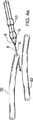
より好適な実施形態では、格納可能な針4と、延びることができるガイドワイヤ6と、一体拡延装置8と、二つの膨張可能なバルーン9及び10とを備えたカテーテル装置(図4)がIMA30の管腔内に導入され、所望の動脈切開位置まで送られることができる。LAD32に対しIMA30を位置決めした後、図4a及び図4bに示すように、針4が延ばされ、IMA30の壁とLAD32の壁との両方に開口を形成するために使用される。図4bに示すように、LAD32内の針により、ガイドワイヤ6がLAD32内に送られる。次いで図4cに示すように、IMA30から両方の動脈切開部を通ってLAD32内までガイドワイヤ6を延ばして残したまま、針4がカテーテル装置内に格納される。カテーテル装置は、一体拡延装置8が両方の動脈切開部を通して押動され、動脈切開部が拡げられるように、ガイドワイヤ6に沿って進められる。ここで使用される一体拡延装置8は、カテーテル装置の遠位端部にテーパ状であって一般に円錐形の外形を備えた部分を有する。この一体拡延装置の近位の周囲はカテーテル装置の外径とほぼ同様になっており、遠位の周囲は近位の周囲よりも小さくなっている。カテーテル装置は、遠位バルーン9がLAD32内に横設されるまでLAD32内に更に挿入される。次いで遠位バルーン9が膨張され、LAD32内に遠位バルーン9が固定される。次いで近位バルーン10が膨張され、IMA30内に近位バルーン10が固定され、図4dに示すようにIMA30とLAD32とが並べられて固定される。次いで図4eに示すように吻合部位をシールするために生物接着剤34が付される。吻合部位36の一体性を維持するのに十分な強度に生物接着剤34がなるまで、典型的には約30秒から5分の間、カテーテル装置はそのまま残される。次いでカテーテル装置が取り外され、図4fに示すように吻合部位36に対し遠位側のIMA30がクリップ止めされるか、又はくくられる。次いで吻合部位に対し近位側のクランプがIMAから取り外される。
【0031】
あるいは、ダブルバルーンカテーテルは互いに対し摺動可能なバルーンを有することも可能である。つまり、他方のバルーンが固定された状態で、一方のバルーンがその他方のバルーンの側又はその反対側に摺動する。例えば、調節可能なダブルバルーンカテーテルが、IMAの切開した遠位端部から導入され、IMA内を近位側に送られ、IMAの動脈切開部及びLADの動脈切開部を通してLAD内に送られる。次いで近位バルーン及び遠位バルーンが動脈切開部にすぐ隣接して位置決めされる。バルーンの位置決め後、LAD内に遠位バルーンを固定するのに十分なだけ遠位バルーンが膨張される。次いで近位バルーンがIMA内で膨張される。次いで遠位バルーンが近位バルーンの側に近づけられる、又は摺動され、二つのバルーン間の距離及び二つの動脈切開部間の距離が小さくされる。近位バルーン及び遠位バルーンがそれぞれの動脈切開部のすぐ内側で互いにすぐ向き合って配置されるまで両方のバルーンが互いに近づく側に移動される。このように摺動させて調節することにより、動脈切開部が正確に位置合わせされる。必要な場合、調節可能なダブルバルーンカテーテルは、定められた関係に二つのバルーンを保持する固定機構を有することが可能である。二つのバルーンを位置決めして固定することは接着処置に特に役立つ。
【0032】
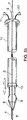
他の実施形態では、図5bに示すように、調節可能なカテーテル装置は、格納可能な針4と、延びることができるガイドワイヤ6と、一体拡延装置と、膨張可能な遠位バルーン9と、膨張可能な遠位バルーン9に対し摺動可能な近位栓子装置13とを有する。ここで使用される栓子装置は、カテーテル装置の拡げられた環状部分であって、その拡げられた環状部分に隣接するカテーテルハウジングの直径よりも大きい直径を有する部分のことをいう。栓子装置の直径は、膨張されると膨張可能な遠位バルーンの直径とほぼ同様になり、格納可能な針により形成された開口よりも大きい。栓子装置はカテーテル装置と一体であることが可能であり、あるいは、Oリングのように別個の取り外し可能な部材であることも可能である。
【0033】
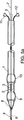
本発明の他の実施形態は本発明の方法に使用するためのカテーテル装置に関する。図5に示すこのカテーテル装置は可撓性の管状構造体1であり、この構造体1はその長手方向に延びている少なくとも一つの穴2を有する。好適にはこの装置は一つの大きい中央穴と二つの小さい穴とを有する。管状の第一構造体1内には可撓性の第二構造体3が配置され、第二構造体3は管状の第一構造体内を摺動可能であり、大きい中央穴2内に配置される。管状の第二構造体3の遠位端部には中空の格納可能な針4が取付けられている。管状の第二構造体3とそれに取付けられた針4とは、針が器官の壁に穴をあけ得るように延ばされた位置に針4を保持するための手段5と、針4が管状の第一構造体1の中央穴2内に完全に引っ込められ得るように針4を格納するための手段とを針の反対側の端部(近位端部)に有する。
【0034】
管状の第二構造体3は、少なくとも装置の長さ分だけ延びており管状の第二構造体3及び針4内で摺動可能なガイドワイヤ6を有する。ガイドワイヤ6の近位端部には、針4の遠位端部を通してガイドワイヤ6を延ばすための手段7と、針が格納されている時にガイドワイヤを延ばされた位置に維持するための手段とが配置されている。管状の第一構造体1と管状の第二構造体3とは共にガイドワイヤ6上を摺動可能であり、必要な場合には共に固定可能である。管状の第一構造体1は遠位端部8がテーパ状にされている。あるいは、管状の第一構造体1の遠位端部にテーパ状の別個の拡延装置を取付けることも可能である。
【0035】
膨張可能な第一バルーン9は管状の第一構造体の遠位端部の近位側に配置され、膨張可能な第二バルーン10は膨張可能な第一バルーンの近位側に配置されている。膨張可能な第一バルーン及び膨張可能な第二バルーンは、ポート(11及び12)あるいは液体又は気体を使用してバルーン9及び10を膨張させるための他の手段に取付けられている。好適には、膨張可能な第一バルーン及び膨張可能な第二バルーンは、膨張された二つのバルーンの間の二つの構造物の壁が押しつぶされる又は損傷を受けることなくそれらの壁を並置することができるように十分な間隔を隔てて位置決めされている。それらの構造物が血管であるとき、二つのバルーンを分離する距離は好適には約1〜2mmである。この距離は接合すべき器官に依存して変わる。
【0036】
本発明の装置の寸法は、接合すべき器官に依存して変更可能であるが、好適には内視鏡心臓バイパス手術に使用可能な寸法にされる。
【0037】
カテーテル装置の他の実施形態では、膨張可能な第二バルーン10は摺動装置14に取付けられる。この摺動装置14は、接合すべき器官の壁が並置して保持されるように膨張可能なバルーンの位置を固定するための手段を有する。あるいは、膨張可能な第二バルーンは栓子装置13に置換可能であり、その栓子装置13は、針により形成された動脈切開部よりも大きく、摺動装置14に取付けられている。例えば、栓子装置13は摺動装置14と一体の部分である。あるいは、栓子装置13は、図5bに示すように摺動機構に取付けられたOリングのような、摺動装置14に取付けられる別個の構造体である。栓子装置13は膨張可能な第二バルーン10と同様に動脈切開部を互いに並置して保持するのに役立つ。
【0038】
後述する限定ではない実施例を参照して本発明を更に説明する。
【0039】
実施例1
生物接着剤が混合用先端部を備えた押出し装置により二つの溶液を押し出して混合された。一方の溶液は45質量%ウシ血清アルブミンを含有し、第二の溶液は10質量%グルタルアルデヒドを含有した。アルブミン溶液とグルタルアルデヒド溶液とはアルブミンとグルタルアルデヒドの体積比が4:1で混合された。採取された人の伏在静脈が互いに隣接して位置決めされ固定された。静脈を切開することにより両方の静脈に小さい開口が形成された。開口の寸法は、その開口を通して血管内膜切除シャントを導入するのに必要な寸法とされた。シャントの一端が一方の静脈(静脈1)の管腔内に送られ、その静脈の開口及び第二静脈(静脈2)の開口を通して第二静脈内に送られた。静脈1内に配置された遠位バルーンが膨張され、二つの血管が手で共に押しつけられ、切開部が直接並置された。生物接着剤が混合され、よいシールを行うために切開部のまわりを物質が完全に覆うように注意しながら付された。吻合部位が接着剤により完全に覆われた後、接着剤が2分間硬化され、シャントが取り外された。
【0040】
次いで吻合部位の開通性及び一体性の検査が行われた。カニューレにより注射器が一方の静脈に取付けられた。カニューレを通して液体が送られ、血管を通る流れのデモンストレーションが行われた。注射器の反対側の血管の端部にクランプが配置され、カニューレを通して液体が更に注入され、第二静脈から液体が観察された。切開部間の開口は開通していた。第二血管の一端がクランプされ、他端に圧力ゲージが取付けられた。次いで液体が加えられ、吻合部位に漏れが発生することなく370mmHgの圧力が達成された。漏れ検査の後、吻合部位の反対側で両方の血管が開かれ、吻合部位が露出された。吻合部位はきれいなままであり、血管同士は近接したまま並置されており、切開しろはすり減っていなかった。
【0041】
実施例2
生物接着剤が混合用先端部を備えた押出し装置により二つの溶液を押し出して混合された。一方の溶液は45質量%ウシ血清アルブミンを含有し、第二の溶液は10質量%グルタルアルデヒドを含有した。アルブミン溶液とグルタルアルデヒド溶液とはアルブミンとグルタルアルデヒドの体積比が4:1で混合された。豚の心臓と採取された人の伏在静脈とが互いに隣接して位置決めされ固定された。静脈に開口が形成され、心臓のLADに切開部が形成された。開口及び切開部の両方は血管内膜切除シャントを導入するのに必要な寸法に形成された。シャントの一端が、静脈の切開端を通して静脈の管腔内に送られ、静脈の開口及びLADの切開部を通してLAD内に送られた。LAD内に配置された遠位バルーンが膨張され、静脈とLADとが手で共に押しつけられ、開口と切開部とが直接並置された。次いで近位バルーンが膨張された。生物接着剤が混合され、よいシールを行うために切開部のまわりを物質が完全に覆うように注意しながら付された。吻合部位が接着剤により完全に覆われた後、接着剤が2分間硬化され、シャントが取り外された。
【0042】
次いで吻合部位の開通性及び一体性の検査が行われた。カニューレが伏在静脈に接続され、三方弁がカニューレに取付けられた。一つのポートに対し水を含んだ注射器が取付けられた。三方弁の第二ポートに対し圧力モニタが取付けられた。次いで吻合部位に対しLADの近位側及び遠位側の両方がクランプされ、伏在静脈がカニューレの反対側の端部においてクランプされた。次いで水が注入され、吻合部位のまわりで漏れが発生することなく圧力が370mmHgまで上昇した。漏れ検査の後、吻合部位の反対側で両方の血管が開かれ、吻合部位が露出された。吻合部位はきれいなままであり、血管同士は近接したまま並置されており、切開しろはすり減っていなかった。
【0043】
豚の心臓のLADに伏在静脈を取付けることは、鼓動している心臓がなくても本発明の鼓動する心臓の冠状バイパス処置を生体外で行うことのデモンストレーションとなる。
【0044】
血管内膜切除シャントが本発明の実験室テストに使用された。血管内膜切除シャントは管状部分により分離された二つの膨張可能なバルーンとそれらの膨張可能なバルーンを膨張させるための手段とを有する。しかしながら、血管内膜切除シャントは心臓バイパス処置に使用することができない。というのは、液体がシャント及び両方のバルーンを通って流れてしまう中央穴を血管内膜切除シャントが有するからである。そのような穴により、血液は吻合すべき動脈から流出してしまい、それゆえ、出血してしまうからである。それゆえ、血管内膜切除シャントは実験室で技術のデモンストレーションを行うのに有益であるが、実際の外科手術状況下では有益ではない。
【0045】
当業者であれば例としての実施形態で説明した構成の原理を変更することが可能であることが理解されるであろう。それゆえ、そのような変形、修正及び置換は本発明の範囲内に含まれるものである。
【図面の簡単な説明】
【図1】 動脈切開部40において並置された二つの管状の器官を示す。
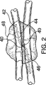
【図2】 図1の動脈切開部40を通されたダブルバルーンカテーテル装置42と器官を共に保持するために膨張されたバルーン44及び46とそれらに対する生物接着剤48の相対位置とを示す。
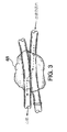
【図3】 本発明の方法により遮断された冠状動脈を他の血管に接合した後の血管吻合部位を示す。破線は血管内に血液の流れの向きを示す。
【図4】 本発明によりIMAとLADとの間に血管吻合を形成する工程の例を示す。
【図5】 ダブルバルーンカテーテル装置の二つの実施形態を示す。[0001]
Background art
As part of the treatment of trauma and the course of many illnesses, it is often necessary to join blood vessels to re-create blood flow to several parts or organs of the body. Such joining of blood vessels is called vascular anastomosis. Conventionally, the main method for closing a vascular anastomosis site has been hand-suture. This method remains an option in many surgical disciplines and surgical procedures. In many surgical procedures, sufficient time exists and the surgical site is suitable for hand suturing and anastomosing the blood vessels. For example, surgical approaches that take anesthetics that are traditionally used in many cardiac bypass procedures require access and fixation of the site to manually perform the sutures required for vascular anastomosis. It was.
[0002]
In conventional coronary artery bypass surgery, the patient's sternum is split and retracted, and the chest is opened. Standard coronary artery bypass surgery approaches are too frequent and costly to avoid illness and death. By using a surgical procedure that does not go too far, the healing time will be shortened, pain will be reduced, and post-surgery complications will be reduced.
[0003]
In recent years, there has been a shift to a surgical operation in which cardiac bypass surgery is not excessive. Although there are several descriptions of endoscopic heart surgery, endoscopic heart bypass surgery has not been possible. Endoscopic cardiac bypass surgery has at least two major technical problems with respect to vascular anastomosis. First of all, the exposure and the manual operation in the surgical operation do not take into account the suturing by hand. Secondly, the blood vessels adjacent to the beating heart must be anastomosed when the blood in the blood vessels is moving. Therefore, in order to perform a vascular anastomosis during endoscopic cardiac bypass surgery, a method of anastomosing the blood vessels without manually suturing when blood in at least one blood vessel is moving is required. At present, a suitable vascular anastomosis technique for anastomosing blood vessels through a small surgical window such as a laparoscopic or endoscopic window is suitable for moving blood in at least one blood vessel or for organs in the surgical area. It doesn't exist in moving situations.
[0004]
Even if the limited exposure that blood in the blood vessel is moving is limited because it is exposed by surgery, it still takes time to perform suturing by hand. . Therefore, there has always been a demand for a blood vessel anastomosis method that can be quickly performed while having strength and reliability as in the case where suture is performed manually. Less time-consuming anastomosis techniques will shorten the surgical time and, as a result, reduce patient illness and mortality, particularly with lengthy surgical procedures. The present invention solves this problem by providing a method for rapidly anastomosing blood vessels.
[0005]
Disclosure of the invention
The present invention joins body organs by juxtaposing the openings of one or more hollow body organs juxtaposed so that blood or other substances can move between the body organs. The present invention relates to a method of applying a sufficient amount of bioadhesive to join body organs. The bioadhesive used in the present invention is a cross-linked protein material that is non-toxic and quickly sets. This method can be applied to join organs side-to-side, end-to-side, or end-to-side, and is preferably used for blood vessels, lymph vessels or intestinal organs. This method is particularly useful for surgery in situations where one of the organs is moving, such as when surgery is performed on a beating heart artery.
[0006]
In a further embodiment of the invention, when the method is used to join two blood vessels side-to-side, extending the guide wire through the opening from the first lumen into the second lumen. Sending a double balloon catheter along the guide wire to position the balloon within each lumen, and inflating the balloon to keep the openings in juxtaposition so that the blood vessels do not move Including. This method is suitable for performing endoscopic cardiac bypass surgery while the heart is beating while the internal thoracic artery is joined to the branch of the left coronary artery.
[0007]
The present invention further relates to a double balloon catheter that maintains the openings of two hollow body organs in juxtaposition to apply a bioadhesive. In particular, the invention relates to a device having a flexible elongated first structure with a first longitudinal lumen, an annular inflatable proximal balloon and an annular inflatable distal balloon. During the operation, the annular inflatable distal balloon is a distal portion of the elongated first structure so that the annular inflatable distal balloon is disposed within one lumen of the hollow body organs to be joined. Around. An annular inflatable proximal balloon is provided about the elongated first structure and proximal to the distal balloon. The device can further have separate additional longitudinal lumens for inflating the proximal and distal balloons with liquid or gas within the elongated first structure. Alternatively, the elongated first structure has two additional longitudinal lumens, a proximal balloon lumen and a distal balloon lumen. The device further has a flexible elongated second structure slidably received within the first longitudinal lumen. The distal end of the elongate second structure has a tip or needle for puncturing tissue. The elongated second structure further has a longitudinal lumen extending from the proximal end of the elongated second structure to the distal end of the tip for piercing.
[0008]
The elongated second structure can be selectively extended distally beyond the distal end of the elongated first structure and can also be secured in the extended position. As a result, it is possible to use the tip for drilling holes in the walls of the organs to be joined. The elongated second structure has a second retracted position where it can be secured. In the retracted position, the tip for puncturing is housed within the elongated first structure without damaging the organ tissue.
[0009]
The device can further include a guidewire slidably received within the second longitudinal lumen. The guidewire has a guide position where the distal end of the guidewire extends distally beyond the distal end of the tip for piercing the elongated second structure, and the guidewire has a distal end. The upper end portion can be moved to two positions, that is, a non-guide position stored inside the front end portion for making a hole.
[0010]
In other embodiments, the proximal balloon and the distal balloon are slidable relative to each other so as to be movable toward or away from each other. In this embodiment, the device has a flexible elongated first structure with an annular inflatable proximal balloon disposed around the distal portion. The elongated first structure further has a longitudinal lumen extending into the elongated first structure. The device further includes a flexible elongated second structure slidably received within the first longitudinal lumen, the elongated second structure being an annular inflation disposed about a distal portion thereof. It has a possible distal balloon. When the device is in the surgical position, the distal balloon is housed in the second body organ and the proximal balloon is housed in the first body organ. This device of this embodiment is such that the juxtaposed position where the inflatable proximal balloon and the inflatable distal balloon are close to each other and the distance between the inflatable proximal balloon and the inflatable distal balloon are juxtaposed. It has two positions for the proximal balloon and the distal balloon, with a non- juxtaposed position that is larger than the position case.
[0011]
The device of this embodiment further has a second longitudinal lumen extending within the second elongated structure, and a flexible elongated third structure slidably received within the second longitudinal lumen. . The distal end of the elongated third structure forms a tip for puncturing tissue. The device includes a drilling position where a tip for puncturing tissue extends distally beyond the distal end of the elongated second structure, and a first tip for puncturing tissue. Storage locations stored within the two structures, and the device can be arbitrarily fixed at those locations.
[0012]
The device can further include a third longitudinal lumen extending within the elongated third structure and a guidewire slidably received within the third longitudinal lumen. The guide wire has a guide position where the distal end of the guide wire extends distally beyond the distal end of the tip for drilling, and a third structure in which the distal end of the guide wire is elongated. It can be moved to two positions: a non-guide position stored inside the tip for drilling a body hole.
[0013]
In other embodiments, a longitudinal lumen extending within the first elongated structure from the inflatable proximal balloon to the proximal end of the elongated first structure, and a second elongated structure from the inflatable distal balloon. A longitudinal lumen extending within the elongated second structure to the second proximal end thereof.
[0014]
BEST MODE FOR CARRYING OUT THE INVENTION
The present invention provides a method of joining a plurality of organs, at least one of which has a recess inside, using a bioadhesive comprising a cross-linked protein material. Specifically, the present invention provides a method for joining hollow body organs, wherein the openings of the body organs are maintained side by side and the body organs are joined using the bioadhesive of the present invention. . The amount of bioadhesive used can be determined by connecting the joined organs so that the openings communicate with each other so that material can move from one organ to the other through the openings as shown in FIGS. The amount is sufficient to seal.
[0015]
“Hollow body organ” and “organ” are used interchangeably herein, but are not limited to veins, arteries, lymph vessels, esophagus, stomach, duodenum, jejunum, ileum, colon, rectum, urine Includes bladder, ureter, gallbladder, bile duct, pancreatic duct, pericardium, peritoneum, and pleura. Preferably, the body organs to be joined are parts of veins, arteries and intestinal tracts. Optimally, the organs to be joined are arteries.
[0016]
The opening can be formed in the organs to be joined by incising the organ walls using a scalpel, radium surgical unit, laser, trocar, needle or other means. The opening can also be formed using a device with a retractable needle. These openings are large enough so that the instrument used to keep the openings juxtaposed can be introduced into the organ recess. The size of the opening can be determined by whether the anastomosis is about to function (eg, the relationship between liquid and semi-liquid in the intestinal contents) or whether the substance is about to pass through the anastomosis site. Alternatively, an opening may already be present in the organ, as in the case of an end of a tubular organ or already formed by trauma.
[0017]
Organ openings can be maintained in juxtaposition by hand or using devices introduced into each organ. This device can assist in positioning the openings such that the openings are in contact with each other. When the opening is grasped together, an anastomosis site is formed at the boundary position between the two organs, and the bioadhesive of the present invention is applied thereto. The device can be attached to each organ using, for example, an inflatable balloon that is secured within the organ when inflated. The inflatable balloons can be attached to each other by means extending through the opening. For example, the device of the present invention can expand the anastomosis site, and can perform the adhesion treatment while keeping the lumen to be anastomosed in contact.
[0018]
While the bioadhesive is applied and cured, the openings are generally maintained in juxtaposition. When the bioadhesive is cured, the interior of the two organs can communicate through the joined openings. Communication between two organs means that fluid or other material can flow from one organ into the other, typically as in the case of a pair of organs joined. Examples of materials that can flow through the anastomotic site include, but are not limited to, liquids and semi-solids such as blood, urine, lymph, bile, pancreatic juice, food and drink and suppuration waste.
[0019]
The bioadhesive of the present invention can adhere to biological tissue and can be cured rapidly (typically in about 30 seconds to about 5 minutes), preferably in a wet state. And a non-toxic adhesive that can be bonded to both biological tissue and synthetic material and can provide sufficient strength to secure the anastomosis site. A bioadhesive composition comprising a material characterized by protein and a cross-linking agent has such characteristics. A bioadhesive composition comprising a protein and a cross-linking agent is disclosed in US Pat. No. 5,385,606, incorporated herein by reference, and is a suitable bioadhesive for use in the method of the present invention. .
[0020]
US Pat. No. 5,385,606 discloses a bioadhesive composition comprising 1) 27-53 wt% protein material and 2) a di- or poly-dioxide having a mass ratio of 1 mass part for every 20-60 parts of protein present. Contains two components with aldehyde. The two parts are mixed and allowed to react on the surface to be bonded. The joint is formed very quickly and generally does not require a minute to complete the joint. The resulting bond is very strong and generally has a tear strength of 400-600 g / cm.2 It becomes a combination. 1300 g / cm2 The tear strength of is obtained.
[0021]
The bioadhesive is applied by extruding a solution of the two components through an extrusion device with a mixing tip. The bioadhesive is pushed over the interface between the two organs and allows the opening to communicate while surrounding the anastomosis site to securely hold the two anastomosed organs together. During an anastomosis with a flexible or rigid endoscope, the bioadhesive is applied by an applicator directed through the endoscope or by an applicator introduced into the surgical area through a different opening. .
[0022]
It should be noted that the method of the present invention can be used in other surgical procedures for joining organs as well as in all surgical tube fields. Examples of feasible anastomoses include, but are not limited to, arterial anastomosis, venous anastomosis, lymphatic anastomosis, gastroesophageal anastomosis, gastroduodenal anastomosis, gastrojejunostomy, jejunal or intrajejunostomy, Includes anastomosis of the ileum, colon and rectum, ureter bladder, anastomosis of the gallbladder or bile duct to the duodenum, and anastomosis of the pancreatic duct to the duodenum. Preferably, the method is used for vascular and gastrointestinal anastomoses. More preferably, this method is used for arterial anastomosis.
[0023]
More preferably, the present invention relates to a method of joining or anastomosing tubular organs side to side or end to side using a bioadhesive.
[0024]
The details of the present invention can be illustrated by the term coronary bypass surgery. For example, an anastomosis of the medial thoracic artery (hereinafter “IMA”) to the left coronary artery branch for supplying blood flow to the left coronary artery can be performed as described below.
[0025]
The IMA is separated from the chest wall and clamped at a position proximal to the target anastomosis site. The IMA is completely incised at a location distal to the target anastomosis site and the artery is lifted for the rest of the procedure. By opening the arterial wall, an opening or arteriotomy is made in the IMA. The host artery, which is the artery to be anastomosed with the IMA, is then separated and an arteriotomy is performed at the appropriate site. For coronary bypass surgery, the host artery is often the branch of the left coronary artery, typically the descending (interventricular) branch of the left coronary artery (hereinafter “LAD”).
[0026]
A device is used to fix the arteriotomy in juxtaposition with each other. For example, a double balloon catheter can be used to fix the arteriotomy. The double balloon catheter is introduced into the IMA through the dissected distal end and passed proximally through the IMA toward the anastomosis site. The catheter is then passed through the IMA arteriotomy and into the LAD arteriotomy. The catheter is then placed on the appropriate proximal side in the LAD so that one balloon (proximal balloon) is placed in the IMA and the second balloon (distal balloon) is placed in the LAD. Sent to a distance position.
[0027]
The distal balloon is inflated until there is sufficient pressure to secure the balloon in the LAD. After the distal balloon is inflated and secured, the IMA is positioned along the LAD so that the arteriotomy is directly apposed. The proximal balloon is then inflated to be secured within the IMA. With this configuration, the arteriotomy can be held side by side regardless of the beating heart motion.
[0028]
Bioadhesive is then applied around the arteriotomy that is juxtaposed in an amount sufficient to seal the anastomosis site. The catheter is maintained in the anastomosis site with the balloon inflated until the bioadhesive is strong enough to maintain the integrity of the anastomosis site.
[0029]
When the adhesive strength is appropriate, the balloon of the double balloon catheter is deflated and the catheter is removed. The distal end of the IMA can use sutures, staples or clips, and the proximal clamp is removed from the IMA. As a result, a blood flow that flows from the IMA through the anastomosis site into the LAD is formed.
[0030]
In a more preferred embodiment, a catheter device (FIG. 4) comprising a retractable needle 4, an
[0031]
Alternatively, double balloon catheters can have balloons that are slidable relative to each other. That is, in a state where the other balloon is fixed, one balloon slides on the other balloon side or the opposite side. For example, an adjustable double balloon catheter is introduced from the dissected distal end of the IMA and sent proximally through the IMA and through the IMA arteriotomy and the LAD arteriotomy into the LAD. The proximal and distal balloons are then positioned immediately adjacent to the arteriotomy. After balloon positioning, the distal balloon is inflated enough to secure the distal balloon within the LAD. The proximal balloon is then inflated in the IMA. The distal balloon is then moved closer to the side of the proximal balloon or slid to reduce the distance between the two balloons and the distance between the two arteriotomy. Both balloons are moved closer together until the proximal and distal balloons are placed just inside each arteriotomy and facing each other. By sliding and adjusting in this way, the arteriotomy is accurately aligned. If necessary, the adjustable double balloon catheter can have a locking mechanism that holds the two balloons in a defined relationship. Positioning and securing the two balloons is particularly useful for the bonding procedure.
[0032]
In other embodiments, as shown in FIG. 5b, the adjustable catheter device comprises a retractable needle 4, an
[0033]
Another embodiment of the invention relates to a catheter device for use in the method of the invention. The catheter device shown in FIG. 5 is a flexible tubular structure 1, which has at least one hole 2 extending in the longitudinal direction thereof. The device preferably has one large central hole and two small holes. A flexible second structure 3 is disposed in the tubular first structure 1, and the second structure 3 is slidable within the tubular first structure and is disposed in the large central hole 2. The A hollow retractable needle 4 is attached to the distal end of the tubular second structure 3. The tubular second structure 3 and the needle 4 attached thereto comprise means 5 for holding the needle 4 in an extended position so that the needle can puncture the organ wall, and the needle 4 is tubular. And a means for storing the needle 4 so that it can be fully retracted into the central hole 2 of the first structure 1 at the opposite end (proximal end) of the needle.
[0034]
The tubular second structure 3 extends at least the length of the device and has a tubular second structure 3 and a
[0035]
An inflatable
[0036]
The dimensions of the device of the present invention can vary depending on the organs to be joined, but are preferably sized for use in endoscopic cardiac bypass surgery.
[0037]
In another embodiment of the catheter device, the inflatable
[0038]
The invention will be further described with reference to the following non-limiting examples.
[0039]
Example 1
The bioadhesive was mixed by extruding the two solutions with an extruder equipped with a mixing tip. One solution contained 45 wt% bovine serum albumin and the second solution contained 10 wt% glutaraldehyde. The albumin solution and the glutaraldehyde solution were mixed at a volume ratio of albumin and glutaraldehyde of 4: 1. The saphenous vein of the harvested person was positioned and fixed adjacent to each other. A small opening was made in both veins by incising the veins. The dimensions of the opening were those required to introduce an endometrial ablation shunt through the opening. One end of the shunt was sent into the lumen of one vein (vein 1) and through the opening of that vein and the opening of the second vein (vein 2) into the second vein. The distal balloon placed in vein 1 was inflated, the two blood vessels were pressed together by hand, and the incision was directly juxtaposed. The bioadhesive was mixed and applied with care so that the material completely covered the incision to make a good seal. After the anastomosis site was completely covered by the adhesive, the adhesive was cured for 2 minutes and the shunt was removed.
[0040]
The anastomosis site was then examined for patency and integrity. A syringe was attached to one vein by a cannula. Fluid was pumped through the cannula to demonstrate flow through the vessel. A clamp was placed at the end of the blood vessel opposite the syringe and liquid was further injected through the cannula and liquid was observed from the second vein. The opening between the incisions was open. One end of the second blood vessel was clamped and a pressure gauge was attached to the other end. Liquid was then added and a pressure of 370 mm Hg was achieved without leaking at the anastomosis site. After the leak test, both vessels were opened on the opposite side of the anastomosis site, exposing the anastomosis site. The anastomosis site remained clean, the blood vessels were juxtaposed in close proximity and the incision was not worn.
[0041]
Example 2
The bioadhesive was mixed by extruding the two solutions with an extruder equipped with a mixing tip. One solution contained 45 wt% bovine serum albumin and the second solution contained 10 wt% glutaraldehyde. The albumin solution and the glutaraldehyde solution were mixed at a volume ratio of albumin and glutaraldehyde of 4: 1. The pig heart and the harvested person's saphenous vein were positioned and fixed adjacent to each other. An opening was made in the vein and an incision was made in the heart LAD. Both the opening and incision were dimensioned to introduce the endometrial ablation shunt. One end of the shunt was routed through the vein incision into the vein lumen and through the vein opening and LAD incision into the LAD. The distal balloon placed in the LAD was inflated, the vein and LAD were pressed together by hand, and the opening and incision were placed directly side by side. The proximal balloon was then inflated. The bioadhesive was mixed and applied with care so that the material completely covered the incision to make a good seal. After the anastomosis site was completely covered by the adhesive, the adhesive was cured for 2 minutes and the shunt was removed.
[0042]
The anastomosis site was then examined for patency and integrity. A cannula was connected to the saphenous vein and a three-way valve was attached to the cannula. A syringe containing water was attached to one port. A pressure monitor was attached to the second port of the three-way valve. The proximal and distal sides of the LAD were then clamped against the anastomosis site and the saphenous vein was clamped at the opposite end of the cannula. Water was then injected and the pressure rose to 370 mmHg without leaking around the anastomosis site. After the leak test, both vessels were opened on the opposite side of the anastomosis site, exposing the anastomosis site. The anastomosis site remained clean, the blood vessels were juxtaposed in close proximity and the incision was not worn.
[0043]
Attaching the saphenous vein to the LAD of the pig's heart is a demonstration of performing the coronary bypass procedure of the beating heart of the present invention in vitro even without a beating heart.
[0044]
An endometrial resection shunt was used for the laboratory test of the present invention. The endarterectomy shunt has two inflatable balloons separated by a tubular portion and means for inflating the inflatable balloons. However, endometrial resection shunts cannot be used for cardiac bypass procedures. This is because the endometrial shunt has a central hole through which fluid can flow through the shunt and both balloons. Such holes cause blood to flow out of the artery to be anastomosed and therefore bleed. Therefore, an endometrial shunt is useful for demonstrating the technique in the laboratory, but not for actual surgical situations.
[0045]
One skilled in the art will appreciate that the principles of the configuration described in the exemplary embodiments can be modified. Therefore, such variations, modifications, and substitutions are intended to be included within the scope of the present invention.
[Brief description of the drawings]
FIG. 1 shows two tubular organs juxtaposed at an
2 shows the double
FIG. 3 shows a vascular anastomosis site after a coronary artery blocked by the method of the present invention is joined to another blood vessel. The broken line indicates the direction of blood flow in the blood vessel.
FIG. 4 shows an example of a process for forming a vascular anastomosis between IMA and LAD according to the present invention.
FIG. 5 shows two embodiments of a double balloon catheter device.
Claims (21)
(a)第一近位端部から第一遠位端部まで延びている可撓性で細長い第一構造体を具備し、第一長手管腔が前記第一近位端部から前記第一遠位端部まで前記細長い第一構造体内で延在し、かつ少なくとも一つの別個の付加的な長手管腔が細長い第一構造体内で第一近位端部から第一遠位端部まで延在し、更に
(b)前記細長い第一構造体の遠位部分のまわりに配置された環状の膨張可能な遠位バルーンと、
(c)前記細長い第一構造体のまわりであって前記膨張可能な遠位バルーンの近位に配置された環状の膨張可能な近位バルーンと、
(d)前記第一長手管腔内に摺動可能に収容された可撓性の細長い第二構造体とを具備し、
前記細長い第二構造体が第二近位端部から第二遠位端部まで延在し、前記第二遠位端部が組織に穴をあけるための先端部を形成し、
前記装置は、手術位置に位置するときに、生物接着剤が硬化するに足りる十分な時間に、前記遠位バルーンを前記第二体器官内に位置決めすると共に、前記近位バルーンを前記第一体器官内に位置決めすることができ、かつ
前記組織に穴をあけるための先端部が、穴あけ位置に位置するときに前記第一遠位端部を越えて遠位側に伸長し、かつ格納位置に位置するときに前記細長い第一構造体内に格納する、装置。A device for joining a hollow first body organ to a hollow second body organ,
(A) a flexible elongated first structure extending from a first proximal end to a first distal end, wherein a first longitudinal lumen extends from the first proximal end to the first; Extending within the elongated first structure to a distal end and at least one separate additional longitudinal lumen extends from the first proximal end to the first distal end within the elongated first structure. And (b) an annular inflatable distal balloon disposed around the distal portion of the elongated first structure;
(C) an annular inflatable proximal balloon disposed about the elongated first structure and proximal to the inflatable distal balloon;
(D) a flexible elongated second structure slidably received in the first longitudinal lumen;
The elongate second structure extends from a second proximal end to a second distal end, the second distal end forming a tip for puncturing tissue;
The device, when positioned in operative position, in sufficient time sufficient to biological adhesive cures, the distal balloon while positioned in said second body organ, said first body to said proximal balloon And a tip for puncturing the tissue extends distally beyond the first distal end when positioned in the puncturing position and is in a retracted position. An apparatus for storing within the elongated first structure when positioned.
前記膨張可能な近位バルーンから前記第一近位端部まで前記細長い第一構造体内で延びている第四長手管腔とを更に具備する、請求項1に記載の装置。A third longitudinal lumen extending within the elongated first structure from the inflatable distal balloon to the first proximal end;
The apparatus of claim 1, further comprising a fourth longitudinal lumen extending within the elongated first structure from the inflatable proximal balloon to the first proximal end.
前記第二長手管腔内に摺動可能に収容されたガイドワイヤとを更に具備し、前記ガイドワイヤが第三近位端部から第三遠位端部まで延在し、
前記第三遠位端部は、ガイド位置にあるときに前記穴をあけるための先端部の遠位端部を越えて遠位側に突出し、非ガイド位置にあるときに前記穴をあけるための先端部の遠位端部から突出しない、請求項1に記載の装置。A second longitudinal lumen extending within the elongated second structure extending from the second proximal end to a distal end of a tip for puncturing the tissue;
A guide wire slidably received within the second longitudinal lumen, the guide wire extending from a third proximal end to a third distal end,
The third distal end projects distally beyond the distal end of the tip for piercing when in the guide position and for piercing the hole when in the non-guide position The device of claim 1, wherein the device does not protrude from the distal end of the tip.
(a)第一近位端部から第一遠位端部まで延びている可撓性の細長い第一構造体と、
(b)前記細長い第一構造体の第一遠位部分のまわりに配置された環状の膨張可能な近位バルーンと、
(c)前記第一近位端部から前記第一遠位端部まで前記細長い第一構造体内で延びている第一長手管腔と、
(d)前記細長い第一構造体内で第一近位端部から第一遠位端部まで延在する少なくとも一つの別個の付加的な長手管腔と、
(e)前記第一長手管腔内に摺動可能に収容された可撓性の細長い第二構造体と、
(f)前記細長い第二構造体の第二遠位部分のまわりに設けられた環状の膨張可能な遠位バルーンと、
(g)前記第二近位端部から前記第二遠位端部まで前記細長い第二構造体内で延びている第二長手管腔と、
(h)前記第二長手管腔内に摺動可能に収容された可撓性の細長い第三構造体とを具備し、
前記細長い第二構造体が第二近位端部から第二遠位端部まで延在し、
前記細長い第三構造体が第三近位端部から第三遠位端部まで延在し、前記第三遠位端部が組織に穴をあけるための先端部を形成し、
前記装置が手術位置に位置するときに、生物接着剤が十分に硬化する時間に、前記遠位バルーンが前記第二体器官内に収容され、前記近位バルーンが前記第一体器官内に収容され、かつ
前記組織に穴をあけるための先端部が、穴あけ位置に位置するときに前記第二遠位端部を越えて遠位側に伸長し、格納位置に位置するときに前記細長い第二構造体内に格納される、装置。A device for joining a hollow first body organ to a hollow second body organ,
(A) a flexible elongated first structure extending from the first proximal end to the first distal end;
(B) an annular inflatable proximal balloon disposed about a first distal portion of the elongated first structure;
(C) a first longitudinal lumen extending within the elongated first structure from the first proximal end to the first distal end;
(D) at least one separate additional longitudinal lumen extending from the first proximal end to the first distal end within the elongated first structure;
(E) a flexible elongated second structure slidably received within the first longitudinal lumen ;
An inflatable distal balloon annular provided around (f) a second distal portion of the elongate second structural member,
( G ) a second longitudinal lumen extending within the elongated second structure from the second proximal end to the second distal end;
(H) slidably accommodated in the a third structure and tool Bei elongate flexible to the second longitudinal lumen,
The elongated second structure extends from a second proximal end to a second distal end ;
The elongated third structure extends from a third proximal end to a third distal end, the third distal end forming a tip for puncturing tissue;
When said device is positioned in operative position, at the time the biological adhesive cures sufficiently, the distal balloon is accommodated in the second body organ, accommodating the proximal balloon to said first body organ And a tip for piercing the tissue extends distally beyond the second distal end when located in the piercing position and the elongated second when located in the retracted position. A device that is stored in a structure.
前記第三長手管腔内に摺動可能に収容されたガイドワイヤとを更に具備し、前記ガイドワイヤが第四近位端部から第四遠位端部まで伸長し、
前記第四遠位端部は、ガイド位置にあるときに前記穴をあけるための先端部の遠位端部を越えて遠位側に伸長し、非ガイド位置にあるときに前記穴をあけるための先端部の遠位端部を越えて伸長しない、請求項10に記載の装置。A third longitudinal lumen extending within the elongated third structure from the third proximal end to a tip for puncturing the tissue;
Further comprising a guide wire slidably received in the third longitudinal lumen, the guide wire is extended from the fourth proximal end to the fourth distal end,
The fourth distal end extends distally beyond the distal end of the tip for piercing when in the guide position, and pierces when in the non-guide position 12. The device of claim 10, wherein the device does not extend beyond the distal end of the tip.
前記膨張可能な遠位バルーンから前記第二近位端部まで前記細長い第二構造体内で延びている第五長手管腔とを更に具備する、請求項10に記載の装置。A fourth longitudinal lumen extending within the elongated first structure from the inflatable proximal balloon to the first proximal end;
The apparatus of claim 10, further comprising a fifth longitudinal lumen extending within the second elongated structure from the inflatable distal balloon to the second proximal end.
前記生物接着剤は、ダブルバルーンカテーテル装置を使用して中空の第一体器官の第一開口を中空の第二体器官の第二開口に並置することにより形成された吻合部位に付与され、かつ前記生物接着剤は、前記第一体器官と前記第二体器官との間に流体または気体が流動するように前記第一開口と前記第二開口とを十分な量で接合している、請求項1から14のいずれか1に記載の装置。An apparatus for use in a structure containing a bioadhesive,
The bioadhesive is applied to the anastomosis site formed by juxtaposing the first opening of the hollow first body organ to the second opening of the hollow second body organ using a double balloon catheter device; and The bioadhesive joins the first opening and the second opening in a sufficient amount so that a fluid or gas flows between the first body organ and the second body organ. Item 15. The apparatus according to any one of Items 1 to 14.
Applications Claiming Priority (3)
| Application Number | Priority Date | Filing Date | Title |
|---|---|---|---|
| US6008697P | 1997-09-26 | 1997-09-26 | |
| US60/060,086 | 1997-09-26 | ||
| PCT/US1998/020071 WO1999016359A1 (en) | 1997-09-26 | 1998-09-25 | Sutureless anastomotic technique using a bioadhesive and device therefor |
Publications (3)
| Publication Number | Publication Date |
|---|---|
| JP2001517524A JP2001517524A (en) | 2001-10-09 |
| JP2001517524A5 JP2001517524A5 (en) | 2006-01-05 |
| JP4205306B2 true JP4205306B2 (en) | 2009-01-07 |
Family
ID=22027251
Family Applications (1)
| Application Number | Title | Priority Date | Filing Date |
|---|---|---|---|
| JP2000513506A Expired - Fee Related JP4205306B2 (en) | 1997-09-26 | 1998-09-25 | Technique for anastomosing using bioadhesive without stitching and apparatus therefor |
Country Status (9)
| Country | Link |
|---|---|
| US (1) | US6685726B2 (en) |
| EP (2) | EP1018944A4 (en) |
| JP (1) | JP4205306B2 (en) |
| KR (1) | KR20010023218A (en) |
| AT (1) | ATE520356T1 (en) |
| AU (1) | AU748152C (en) |
| CA (1) | CA2299407C (en) |
| ES (1) | ES2368847T3 (en) |
| WO (1) | WO1999016359A1 (en) |
Families Citing this family (59)
| Publication number | Priority date | Publication date | Assignee | Title |
|---|---|---|---|---|
| WO1998020939A2 (en) * | 1996-11-15 | 1998-05-22 | Advanced Bio Surfaces, Inc. | Biomaterial system for in situ tissue repair |
| NL1007349C2 (en) * | 1997-10-24 | 1999-04-27 | Suyker Wilhelmus Joseph Leonardus | System for the mechanical production of anastomoses between hollow structures; as well as device and applicator for use therewith. |
| US8888688B2 (en) | 2000-04-03 | 2014-11-18 | Intuitive Surgical Operations, Inc. | Connector device for a controllable instrument |
| US6858005B2 (en) | 2000-04-03 | 2005-02-22 | Neo Guide Systems, Inc. | Tendon-driven endoscope and methods of insertion |
| US6610007B2 (en) | 2000-04-03 | 2003-08-26 | Neoguide Systems, Inc. | Steerable segmented endoscope and method of insertion |
| US6468203B2 (en) | 2000-04-03 | 2002-10-22 | Neoguide Systems, Inc. | Steerable endoscope and improved method of insertion |
| US8517923B2 (en) | 2000-04-03 | 2013-08-27 | Intuitive Surgical Operations, Inc. | Apparatus and methods for facilitating treatment of tissue via improved delivery of energy based and non-energy based modalities |
| US6464665B1 (en) * | 2000-07-05 | 2002-10-15 | Richard R. Heuser | Catheter apparatus and method for arterializing a vein |
| US6953464B2 (en) * | 2001-02-21 | 2005-10-11 | Novare Surgical Systems, Inc. | Anastomosis occlusion device |
| WO2003059151A2 (en) * | 2002-01-09 | 2003-07-24 | Neoguide Systems, Inc. | Apparatus and method for endoscopic colectomy |
| NL1020288C1 (en) | 2002-04-02 | 2003-05-07 | Eric Berreklouw | An assembly comprising a stabilizer and an instrument to be positioned in or around a passage surrounded by body tissue. |
| JP4364796B2 (en) * | 2002-06-20 | 2009-11-18 | タイコ ヘルスケア グループ エルピー | Method and apparatus for joining comprising a fixing sleeve |
| US20040087993A1 (en) * | 2002-08-06 | 2004-05-06 | Shyh-Jen Wang | Auxiliary surgery tool for protruding resected part |
| US9307991B2 (en) | 2002-08-22 | 2016-04-12 | Ams Research, Llc | Anastomosis device and related methods |
| US8551126B2 (en) | 2002-08-22 | 2013-10-08 | Ams Research Corporation | Anastomosis device and related methods |
| US8764775B2 (en) | 2002-08-22 | 2014-07-01 | Ams Research Corporation | Anastomosis device and related methods |
| US8882657B2 (en) | 2003-03-07 | 2014-11-11 | Intuitive Surgical Operations, Inc. | Instrument having radio frequency identification systems and methods for use |
| US7217294B2 (en) | 2003-08-20 | 2007-05-15 | Histogenics Corp. | Acellular matrix implants for treatment of articular cartilage, bone or osteochondral defects and injuries and method for use thereof |
| US8425539B2 (en) | 2004-04-12 | 2013-04-23 | Xlumena, Inc. | Luminal structure anchoring devices and methods |
| US7515970B2 (en) * | 2004-08-18 | 2009-04-07 | Cardiac Pacemakers, Inc. | Transeptal lead |
| US20060111698A1 (en) * | 2004-11-22 | 2006-05-25 | Kihong Kwon | Apparatus and method for performing laser-assisted vascular anastomoses |
| JP5111112B2 (en) | 2004-12-08 | 2012-12-26 | エックスルミナ, インコーポレイテッド | Device for performing needle-guided therapy |
| US8636756B2 (en) | 2005-02-18 | 2014-01-28 | Ams Research Corporation | Anastomosis device and surgical tool actuation mechanism configurations |
| US20060253198A1 (en) * | 2005-05-03 | 2006-11-09 | Disc Dynamics, Inc. | Multi-lumen mold for intervertebral prosthesis and method of using same |
| US20060253199A1 (en) * | 2005-05-03 | 2006-11-09 | Disc Dynamics, Inc. | Lordosis creating nucleus replacement method and apparatus |
| US7645288B2 (en) * | 2005-05-05 | 2010-01-12 | Ethicon Endo-Surgery, Inc. | Anastomotic ring applier with inflatable members |
| US7771443B2 (en) | 2005-05-20 | 2010-08-10 | Ams Research Corporation | Anastomosis device approximating structure configurations |
| US7717928B2 (en) | 2005-05-20 | 2010-05-18 | Ams Research Corporation | Anastomosis device configurations and methods |
| US8784437B2 (en) | 2005-06-09 | 2014-07-22 | Xlumena, Inc. | Methods and devices for endosonography-guided fundoplexy |
| US8777967B2 (en) | 2005-06-09 | 2014-07-15 | Xlumena, Inc. | Methods and devices for anchoring to tissue |
| JP2009516574A (en) | 2005-11-22 | 2009-04-23 | ネオガイド システムズ, インコーポレイテッド | Method for determining the shape of a bendable device |
| US8083879B2 (en) | 2005-11-23 | 2011-12-27 | Intuitive Surgical Operations, Inc. | Non-metallic, multi-strand control cable for steerable instruments |
| WO2007120727A1 (en) * | 2006-04-13 | 2007-10-25 | Wilson-Cook Medical Inc. | Apparatus and methods for endoscopic resection of tissue |
| WO2007137208A2 (en) | 2006-05-19 | 2007-11-29 | Neoguide Systems, Inc. | Methods and apparatus for displaying three-dimensional orientation of a steerable distal tip of an endoscope |
| US8092536B2 (en) * | 2006-05-24 | 2012-01-10 | Disc Dynamics, Inc. | Retention structure for in situ formation of an intervertebral prosthesis |
| US20070276491A1 (en) * | 2006-05-24 | 2007-11-29 | Disc Dynamics, Inc. | Mold assembly for intervertebral prosthesis |
| US8066725B2 (en) | 2006-10-17 | 2011-11-29 | Ams Research Corporation | Anastomosis device having improved safety features |
| US7993264B2 (en) | 2006-11-09 | 2011-08-09 | Ams Research Corporation | Orientation adapter for injection tube in flexible endoscope |
| US8277466B2 (en) | 2006-11-14 | 2012-10-02 | Ams Research Corporation | Anastomosis device and method |
| US8491525B2 (en) | 2006-11-17 | 2013-07-23 | Ams Research Corporation | Systems, apparatus and associated methods for needleless delivery of therapeutic fluids |
| US8361092B1 (en) | 2007-06-18 | 2013-01-29 | Wilson T. Asfora | Vascular anastomosis device and method |
| US10004507B2 (en) | 2007-06-18 | 2018-06-26 | Asfora Ip, Llc | Vascular anastomosis device and method |
| US9504469B2 (en) | 2007-06-18 | 2016-11-29 | Asfora Ip, Llc | Vascular anastomosis device and method |
| US8858576B2 (en) * | 2007-09-10 | 2014-10-14 | Olympus Medical Systems Corp. | Tissue fastening tool, stent, applicator for placing the same, and tissue fastening method through natural orifice |
| US9220398B2 (en) | 2007-10-11 | 2015-12-29 | Intuitive Surgical Operations, Inc. | System for managing Bowden cables in articulating instruments |
| US7850649B2 (en) | 2007-11-09 | 2010-12-14 | Ams Research Corporation | Mechanical volume control for injection devices |
| US8182418B2 (en) | 2008-02-25 | 2012-05-22 | Intuitive Surgical Operations, Inc. | Systems and methods for articulating an elongate body |
| US8454632B2 (en) | 2008-05-12 | 2013-06-04 | Xlumena, Inc. | Tissue anchor for securing tissue layers |
| US20090281379A1 (en) * | 2008-05-12 | 2009-11-12 | Xlumena, Inc. | System and method for transluminal access |
| US8388349B2 (en) | 2009-01-14 | 2013-03-05 | Ams Research Corporation | Anastomosis deployment force training tool |
| US9364259B2 (en) | 2009-04-21 | 2016-06-14 | Xlumena, Inc. | System and method for delivering expanding trocar through a sheath |
| EP2434961B1 (en) | 2009-05-29 | 2015-01-14 | Xlumena, Inc. | Apparatus and method for deploying stent across adjacent tissue layers |
| EP2544623B1 (en) * | 2010-03-09 | 2018-01-10 | Solinas Medical Inc. | Self-closing devices |
| US8747386B2 (en) | 2010-12-16 | 2014-06-10 | Ams Research Corporation | Anastomosis device and related methods |
| US8979842B2 (en) | 2011-06-10 | 2015-03-17 | Medtronic Advanced Energy Llc | Wire electrode devices for tonsillectomy and adenoidectomy |
| US9381335B2 (en) | 2012-03-21 | 2016-07-05 | Ams Research Corporation | Bladder wall drug delivery system |
| EP2854654B1 (en) | 2012-05-17 | 2019-11-06 | Boston Scientific Scimed, Inc. | Devices for access across adjacent tissue layers |
| CN109044438B (en) | 2013-02-21 | 2022-05-13 | 波士顿科学国际有限公司 | Device and method for forming anastomotic stoma |
| CN208927391U (en) * | 2017-11-07 | 2019-06-04 | 南京鼓楼医院 | Dual balloon catheter device for gastrointestinal anastomosis |
Family Cites Families (16)
| Publication number | Priority date | Publication date | Assignee | Title |
|---|---|---|---|---|
| US4731055A (en) * | 1986-08-25 | 1988-03-15 | Becton, Dickinson And Company | Blood flow conduit |
| US5549122A (en) * | 1989-07-26 | 1996-08-27 | Detweilwer; Mark B. | Methods of surgical mammalian vessel anastomosis |
| US5749895A (en) * | 1991-02-13 | 1998-05-12 | Fusion Medical Technologies, Inc. | Method for bonding or fusion of biological tissue and material |
| US5385606A (en) * | 1992-07-06 | 1995-01-31 | Kowanko; Nicholas | Adhesive composition and method |
| US5254113A (en) * | 1992-08-31 | 1993-10-19 | Wilk Peter J | Anastomosis method |
| US5725551A (en) * | 1993-07-26 | 1998-03-10 | Myers; Gene | Method and apparatus for arteriotomy closure |
| FR2726571B1 (en) * | 1994-11-03 | 1997-08-08 | Izoret Georges | BIOLOGICAL GLUE, PREPARATION METHOD AND APPLICATION DEVICE FOR BIOLOGICAL GLUE, AND HARDENERS FOR BIOLOGICAL GLUE |
| US5647380A (en) * | 1995-06-07 | 1997-07-15 | W. L. Gore & Associates, Inc. | Method of making a left ventricular assist device |
| US5702412A (en) * | 1995-10-03 | 1997-12-30 | Cedars-Sinai Medical Center | Method and devices for performing vascular anastomosis |
| US6068637A (en) * | 1995-10-03 | 2000-05-30 | Cedar Sinai Medical Center | Method and devices for performing vascular anastomosis |
| WO1997017025A1 (en) * | 1995-11-07 | 1997-05-15 | Fusion Medical Technologies, Inc. | Methods and articles for fusing matrix layers containing non-collagenous proteins to tissue |
| JP2001508318A (en) * | 1996-02-02 | 2001-06-26 | トランスバスキュラー インコーポレイテッド | Apparatus, systems and methods for interstitial transvascular intervention |
| AU2052197A (en) | 1996-02-20 | 1997-09-02 | Fusion Medical Technologies, Inc. | Compositions and methods for sealing tissue and preventing post-surgical adhesions |
| US5868763A (en) * | 1996-09-16 | 1999-02-09 | Guidant Corporation | Means and methods for performing an anastomosis |
| US5728134A (en) * | 1996-09-17 | 1998-03-17 | Barak; Shlomo | Method and apparatus for hemostasis |
| US6026814A (en) * | 1997-03-06 | 2000-02-22 | Scimed Life Systems, Inc. | System and method for percutaneous coronary artery bypass |
-
1998
- 1998-09-25 EP EP98951939A patent/EP1018944A4/en not_active Withdrawn
- 1998-09-25 KR KR1020007001847A patent/KR20010023218A/en not_active Application Discontinuation
- 1998-09-25 EP EP05014269A patent/EP1584292B1/en not_active Expired - Lifetime
- 1998-09-25 WO PCT/US1998/020071 patent/WO1999016359A1/en not_active Application Discontinuation
- 1998-09-25 AT AT05014269T patent/ATE520356T1/en active
- 1998-09-25 JP JP2000513506A patent/JP4205306B2/en not_active Expired - Fee Related
- 1998-09-25 AU AU97763/98A patent/AU748152C/en not_active Ceased
- 1998-09-25 US US09/161,101 patent/US6685726B2/en not_active Expired - Fee Related
- 1998-09-25 CA CA002299407A patent/CA2299407C/en not_active Expired - Fee Related
- 1998-09-25 ES ES05014269T patent/ES2368847T3/en not_active Expired - Lifetime
Also Published As
| Publication number | Publication date |
|---|---|
| US20020138098A1 (en) | 2002-09-26 |
| EP1584292B1 (en) | 2011-08-17 |
| AU9776398A (en) | 1999-04-23 |
| US6685726B2 (en) | 2004-02-03 |
| EP1018944A1 (en) | 2000-07-19 |
| WO1999016359A1 (en) | 1999-04-08 |
| EP1584292A1 (en) | 2005-10-12 |
| KR20010023218A (en) | 2001-03-26 |
| ATE520356T1 (en) | 2011-09-15 |
| CA2299407A1 (en) | 1999-04-08 |
| CA2299407C (en) | 2007-01-09 |
| JP2001517524A (en) | 2001-10-09 |
| EP1018944A4 (en) | 2001-08-22 |
| AU748152B2 (en) | 2002-05-30 |
| WO1999016359A9 (en) | 1999-07-15 |
| AU748152C (en) | 2004-03-25 |
| ES2368847T3 (en) | 2011-11-22 |
Similar Documents
| Publication | Publication Date | Title |
|---|---|---|
| JP4205306B2 (en) | Technique for anastomosing using bioadhesive without stitching and apparatus therefor | |
| US10736627B2 (en) | Anastomotic staple with capillary which expels a bonding agent upon deformation | |
| US6245083B1 (en) | Sutureless anastomotic technique using a bioadhesive and device therefor | |
| US6068637A (en) | Method and devices for performing vascular anastomosis | |
| US5702412A (en) | Method and devices for performing vascular anastomosis | |
| US20020198546A1 (en) | Vessel eversion instrument with wiping element | |
| US7008436B2 (en) | Method and coupling apparatus for facilitating an vascular anastomoses | |
| US20030225425A1 (en) | Devices and methods for interconnecting vessels | |
| JPH0910219A (en) | Balloon catheter for endoscopic hemostasis | |
| AU763376B2 (en) | Sutureless anastomotic technique using a bioadhesive and device therefor | |
| EP1340462A1 (en) | Sponge for creating an anastomosis between vessels | |
| JP3647025B2 (en) | Gastrointestinal anastomosis balloon catheter | |
| EP1576928A1 (en) | Flanged graft for vascular anastomosis and bypass |
Legal Events
| Date | Code | Title | Description |
|---|---|---|---|
| A521 | Request for written amendment filed |
Free format text: JAPANESE INTERMEDIATE CODE: A523 Effective date: 20050916 |
|
| A621 | Written request for application examination |
Free format text: JAPANESE INTERMEDIATE CODE: A621 Effective date: 20050916 |
|
| A131 | Notification of reasons for refusal |
Free format text: JAPANESE INTERMEDIATE CODE: A131 Effective date: 20061205 |
|
| A601 | Written request for extension of time |
Free format text: JAPANESE INTERMEDIATE CODE: A601 Effective date: 20070302 |
|
| A602 | Written permission of extension of time |
Free format text: JAPANESE INTERMEDIATE CODE: A602 Effective date: 20070312 |
|
| A521 | Request for written amendment filed |
Free format text: JAPANESE INTERMEDIATE CODE: A523 Effective date: 20070605 |
|
| A131 | Notification of reasons for refusal |
Free format text: JAPANESE INTERMEDIATE CODE: A131 Effective date: 20070925 |
|
| A601 | Written request for extension of time |
Free format text: JAPANESE INTERMEDIATE CODE: A601 Effective date: 20071221 |
|
| A602 | Written permission of extension of time |
Free format text: JAPANESE INTERMEDIATE CODE: A602 Effective date: 20080104 |
|
| A521 | Request for written amendment filed |
Free format text: JAPANESE INTERMEDIATE CODE: A523 Effective date: 20080319 |
|
| TRDD | Decision of grant or rejection written | ||
| A01 | Written decision to grant a patent or to grant a registration (utility model) |
Free format text: JAPANESE INTERMEDIATE CODE: A01 Effective date: 20080916 |
|
| A01 | Written decision to grant a patent or to grant a registration (utility model) |
Free format text: JAPANESE INTERMEDIATE CODE: A01 |
|
| A61 | First payment of annual fees (during grant procedure) |
Free format text: JAPANESE INTERMEDIATE CODE: A61 Effective date: 20081016 |
|
| FPAY | Renewal fee payment (event date is renewal date of database) |
Free format text: PAYMENT UNTIL: 20111024 Year of fee payment: 3 |
|
| R150 | Certificate of patent or registration of utility model |
Free format text: JAPANESE INTERMEDIATE CODE: R150 |
|
| FPAY | Renewal fee payment (event date is renewal date of database) |
Free format text: PAYMENT UNTIL: 20121024 Year of fee payment: 4 |
|
| FPAY | Renewal fee payment (event date is renewal date of database) |
Free format text: PAYMENT UNTIL: 20131024 Year of fee payment: 5 |
|
| LAPS | Cancellation because of no payment of annual fees |