JP4199961B2 - Modular plug - Google Patents
Modular plug Download PDFInfo
- Publication number
- JP4199961B2 JP4199961B2 JP2002185921A JP2002185921A JP4199961B2 JP 4199961 B2 JP4199961 B2 JP 4199961B2 JP 2002185921 A JP2002185921 A JP 2002185921A JP 2002185921 A JP2002185921 A JP 2002185921A JP 4199961 B2 JP4199961 B2 JP 4199961B2
- Authority
- JP
- Japan
- Prior art keywords
- twisted pair
- wires
- housing
- hole
- alignment member
- Prior art date
- Legal status (The legal status is an assumption and is not a legal conclusion. Google has not performed a legal analysis and makes no representation as to the accuracy of the status listed.)
- Expired - Fee Related
Links
Images


Classifications
-
- H—ELECTRICITY
- H01—ELECTRIC ELEMENTS
- H01R—ELECTRICALLY-CONDUCTIVE CONNECTIONS; STRUCTURAL ASSOCIATIONS OF A PLURALITY OF MUTUALLY-INSULATED ELECTRICAL CONNECTING ELEMENTS; COUPLING DEVICES; CURRENT COLLECTORS
- H01R13/00—Details of coupling devices of the kinds covered by groups H01R12/70 or H01R24/00 - H01R33/00
- H01R13/646—Details of coupling devices of the kinds covered by groups H01R12/70 or H01R24/00 - H01R33/00 specially adapted for high-frequency, e.g. structures providing an impedance match or phase match
- H01R13/6461—Means for preventing cross-talk
- H01R13/6463—Means for preventing cross-talk using twisted pairs of wires
-
- H—ELECTRICITY
- H01—ELECTRIC ELEMENTS
- H01R—ELECTRICALLY-CONDUCTIVE CONNECTIONS; STRUCTURAL ASSOCIATIONS OF A PLURALITY OF MUTUALLY-INSULATED ELECTRICAL CONNECTING ELEMENTS; COUPLING DEVICES; CURRENT COLLECTORS
- H01R24/00—Two-part coupling devices, or either of their cooperating parts, characterised by their overall structure
- H01R24/60—Contacts spaced along planar side wall transverse to longitudinal axis of engagement
- H01R24/62—Sliding engagements with one side only, e.g. modular jack coupling devices
- H01R24/64—Sliding engagements with one side only, e.g. modular jack coupling devices for high frequency, e.g. RJ 45
-
- Y—GENERAL TAGGING OF NEW TECHNOLOGICAL DEVELOPMENTS; GENERAL TAGGING OF CROSS-SECTIONAL TECHNOLOGIES SPANNING OVER SEVERAL SECTIONS OF THE IPC; TECHNICAL SUBJECTS COVERED BY FORMER USPC CROSS-REFERENCE ART COLLECTIONS [XRACs] AND DIGESTS
- Y10—TECHNICAL SUBJECTS COVERED BY FORMER USPC
- Y10S—TECHNICAL SUBJECTS COVERED BY FORMER USPC CROSS-REFERENCE ART COLLECTIONS [XRACs] AND DIGESTS
- Y10S439/00—Electrical connectors
- Y10S439/941—Crosstalk suppression
Landscapes
- Details Of Connecting Devices For Male And Female Coupling (AREA)
- Coupling Device And Connection With Printed Circuit (AREA)
Description
【0001】
【発明の属する技術分野】
本発明は、モジュラージャックに嵌合するモジュラープラグに関し、特に、2本の電線を撚って形成されたツイストペア線を結線させるためのモジュラープラグに関する。
【0002】
【従来の技術】
一般に、電話設備やLAN(ローカルエリアネットワーク)において使用されるコネクタ部材として、モジュラージャックとモジュラープラグが知られている。このうちモジュラープラグは、モジュラージャックに嵌合し、ケーブル等の複数の電線を結線させるための部材であり、従来のモジュラープラグとしては、例えば、特開平10−134903号公報に開示されているものがある。
【0003】
このモジュラープラグ1は、図16及び図17に示されているように、ハウジング2と、該ハウジング2内に嵌設される整列部材3と、前記ハウジング2の前記整列部材3より基端側に嵌設されるガイドプレート4と、ケーブル5の4組のツイストペア線6A,6B,6C,6Dの撚りを解かれた8本の電線7a,7b,7c,7d,7e,7f,7g,7hに接続される端子8,9と、絶縁ケース10とから概略構成されている。
【0004】
前記ハウジング2は、シールド板11と、該シールド板11の先端側に設けられた絶縁部12とで構成され、該絶縁部12の先端部には8個のスリット孔13が穿設されている。また、前記シールド板11には基端側に延出する圧着部14が形成されている。前記整列部材3はコの字状断面を有し、該整列部材3には、前記電線7a,7b,7c,7d,7e,7f,7g,7hと同数、すなわち、8個の貫通孔15a,15b,15c,15d,15e,15f,15g,15hが上下2段に穿設され、該貫通孔15は隣合う貫通孔15と段が異なるように上下交互に配置されている。また、前記ガイドプレート4には、前記貫通孔15より大径の貫通穴16A,16B,16C,16Dが、前記ツイストペア線6A,6B,6C,6Dと同数、すなわち、4個、上下2段に穿設され、前記貫通穴16は隣合う貫通穴16と段が異なるように上下交互に配置されている。
【0005】
このような構成において、前記モジュラープラグ1を組立てるには、先ず、前記ケーブル5を前記絶縁ケース10に基端側から挿入した状態で、前記4組のツイストペア線6A,6B,6C,6Dをそれぞれ前記各貫通穴16A,16B,16C,16Dに挿入すると共に、撚りを解かれた前記8本の電線7a,7b,7c,7d,7e,7f,7g,7hを前記各貫通孔15a,15b,15c,15d,15e,15f,15g,15hに挿入する。これにより、前記4組のツイストペア線6A,6B,6C,6Dは各組毎に分離された状態で前記ガイドプレート4に保持され、前記8本の電線7a,7b,7c,7d,7e,7f,7g,7hはそれぞれ前記整列部材3に整列保持される。その後、前記各ツイストペア線6及び電線7を保持した前記整列部材3及びガイドプレート4を前記ハウジング2内に嵌設し、前記ケーブル5の外周を圧着部14により固定する。そして、前記ハウジング2の外側から前記スリット孔13を介して前記各端子8,9を挿入し、該各端子8,9をそれぞれ前記8本の電線7a,7b,7c,7d,7e,7f,7g,7hに接続する。
【0006】
【発明が解決しようとする課題】
一般に、モジュラープラグでは、ノイズ等の障害が発生するのを防止するため、いわゆるクロストークの低減が求められており、近年、特に、近端クロストーク(NEXT)の減衰量に対する要求が厳しくなってきている。ところが、上記した従来のモジュラープラグ1では、近端クロストークの減衰量に対する近年の厳しい要求に答えることができないおそれがあった。
【0007】
そこで、本発明は、そのような厳しい近端クロストークの減衰量に対する要求を満たすことのできるモジュラープラグを提供しようとするものである。
【0008】
【課題を解決するための手段】
本発明は、モジュラージャックに嵌合し、ツイストペア線を結線させるためのモジュラープラグであって、ハウジングと;該ハウジング内に嵌設され、複数組の前記ツイストペア線を各組毎に分離させるガイドプレートと;前記ガイドプレートと連結された状態で前記ハウジング内に嵌設され、第1から第4の4組のツイストペア線の先端部の撚りを解かれた8本の電線を上下複数段に整列保持する横方向に連設された貫通孔を有する整列部材であって、該連設された貫通孔に前記8本の電線の全てが挿入される、前記整列部材と;前記各ツイストペア線の先端部の撚りを解かれた電線にそれぞれ接続される端子と;を備え、前記各組毎に分離されたツイストペア線が前記ハウジングの内面と前記ガイドプレートとの間に撚りを解かずに収容されるように構成されており;前記ガイドプレートには、上下左右に、上側溝部、下側溝部、右側溝部、及び左側溝部が形成され、前記上側溝部と前記下側溝部は前記ガイドプレートの前記ハウジングに対する嵌設の方向に沿って一定の厚みを有する水平隔壁により分離され、前記右側溝部と前記上側及び下側溝部は右側垂直隔壁により、前記左側溝部と前記上側及び下側溝部は左側垂直隔壁により、前記右側溝部と前記左側溝部の間の距離が前記ガイドプレートの前記ハウジングに対する嵌設の方向に沿って一定となるように分離されており;前記水平隔壁の上側及び下側の先端側角部、前記右側垂直隔壁の先端側角部、及び前記左側垂直隔壁の先端側角部により、前記ハウジングの内面に接触するまで前記各ツイストペア線を撚った状態のままその内面側に押し広げて前記ハウジング内の空間一杯に広げるように形成されており、前記右側溝部及び左側溝部は、それぞれ、先端方向に向かって上方に傾斜して、外側に配置された第1及び第4ツイストペア線の各電線を上方へ向けて前記整列部材の対応する貫通孔に案内しており;前記貫通孔は、前記第1及び第4ツイストペア線の各電線が下段に配置され、内側に配置された第2及び第3ツイストペア線の各電線が上段に並んで配置されるように形成されており;前記貫通孔の基端側に傾斜面によって拡幅された拡幅部が形成されており、前記拡幅部は、前記貫通孔の基端側において、前記ツイストペア線を前記貫通孔の直近まで撚りを解かずに保持可能であり、前記拡幅部は、前記第2及び第3ツイストペア線の各電線を前記整列部材の対応する貫通孔の上段に案内するように、先端方向に向かって狭まるように傾斜しており、また、前記第1及び第4ツイストペア線の各電線を前記整列部材の対応する貫通孔の下段に案内するように、先端方向に向かって狭まるように傾斜していることを特徴とする。
尚、前記拡幅部は、前記第2及び第3ツイストペア線の各電線を前記整列部材の対応する貫通孔の上段に案内するように、その下方においてのみ先端方向に向かって狭まるように傾斜しており、また、前記第1及び第4ツイストペア線の各電線を前記整列部材の対応する貫通孔の下段に案内するように、その上方及び下方の双方において先端方向に向かって狭まるように傾斜していてもよい。
【0009】
好ましくは、前記ガイドプレートには、上下左右に溝部が形成され、該各溝部はそれぞれ隔壁により分離されている。
【0010】
また、前記隔壁は前記各ツイストペア線を前記ハウジングの内面側に押し広げるように形成されている。
【0011】
さらに、前記隔壁は、その先端側角部により前記各ツイストペア線を前記ハウジングの内面側に押し広げるように形成されている。
【0012】
また本発明は、モジュラージャックに嵌合し、ツイストペア線を結線させるためのモジュラープラグであって、ハウジングと、該ハウジング内に嵌設され、第1から第4の4組のツイストペア線の先端部の撚りを解かれた8本の電線を上下複数段に整列保持する貫通孔を有する整列部材と、前記各ツイストペア線の先端部の撚りを解かれた電線にそれぞれ接続される8個の端子とを備え、前記貫通孔は、それぞれ隣接する第1ツイストペア線の内側の電線と第2ツイストペア線の電線、及び第3ツイストペア線の電線と第4ツイストペア線の内側の電線が異なる段に配置され、前記第2及び第3ツイストペア線の各電線がそれぞれ同一の段に並んで配置されるように形成されていることを特徴とする。
【0013】
好ましくは、前記貫通孔の基端側には、前記各ツイストペア線を前記貫通孔の直近まで撚りを解かずに保持可能な拡幅部が形成されている。
【0014】
さらに本発明は、モジュラージャックに嵌合し、ツイストペア線を結線させるためのモジュラープラグであって、ハウジングと、該ハウジング内に嵌設され、第1から第4の4組のツイストペア線の先端部の撚りを解かれた8本の電線を上下複数段に整列保持する貫通孔を有する整列部材と、前記ハウジング内の前記整列部材より基端側に嵌設され、前記4組のツイストペア線を各組毎に分離させるガイドプレートと、前記各ツイストペア線の先端部の撚りを解かれた8本の電線にそれぞれ接続される8個の端子とを備え、前記貫通孔は、それぞれ隣接する第1ツイストペア線の内側の電線と第2ツイストペア線の電線、及び第3ツイストペア線の電線と第4ツイストペア線の内側の電線が異なる段に配置され、前記第2及び第3ツイストペア線の各電線がそれぞれ同一の段に並んで配置されるように形成され、前記4組のツイストペア線がそれぞれ前記ハウジングの内面と前記ガイドプレートとの間に収容されるように構成されていることを特徴とする。
【0015】
また、前記ガイドプレートには、上下左右に溝部が形成され、該各溝部はそれぞれ隔壁により分離されている。
【0016】
さらに、前記隔壁は前記各ツイストペア線を前記ハウジングの内面側に押し広げるように形成されている。
【0017】
さらにまた、前記隔壁は、その先端側角部により前記各ツイストペア線を前記ハウジングの内面側に押し広げるように形成されている。
【0019】
このような構成により、近端クロストークを低減させることができ、その減衰量を所定範囲内に保持することが可能となる。
【0020】
【発明の実施の形態】
以下、図面を参照しつつ、本発明の実施の形態を説明する。
【0021】
図1〜図15は本発明の実施の形態に係るモジュラープラグの一例を示しており、この例では、モジュラープラグ21が、4組のツイストペア線22A,22B,22C,22Dからなるケーブル23の各電線24a,24a’,24b,24b’,24c,24c’,24d,24d’を結線させるために用いられる。
【0022】
前記モジュラープラグ21は、基端側に嵌合凹部25が形成された絶縁ハウジング26と、前記嵌合凹部25内にそれぞれ嵌設される整列部材27、ガイドプレート28、及びクランプ金具29と、前記絶縁ハウジング26の先端部で前記4組ツイストペア線22A,22B,22C,22Dの撚りを解かれた8本の電線24a,24a’,24b,24b’,24c,24c’,24d,24d’に接続される長短2種類の端子30,31とから概略構成されている。
【0023】
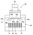
前記絶縁ハウジング26の先端部には、上面側にロック部32が基端方向に向かって斜め上方に延出形成され、下面側に8個のスリット孔33が並列に穿設されている。また、前記絶縁ハウジング26の下面側中央部分には段差部34が形成され、該段差部34の直近基端側に凹部35が2個形成され、該凹部35にそれぞれ係止突起36が形成されている。
【0024】
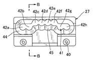
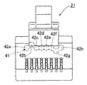
図4は前記整列部材27を基端側から見た正面図であり、図5はその平面図、図6は図4のB−B断面図である。前記整列部材27は、それらの図4〜図6によく示されているように、電線保持部37と、該電線保持部37の両側部分から先端方向に延出するガイド部38と、前記電線保持部37の基端側に形成されたツイストペア線保持部39とを備え、該ツイストペア線保持部39の両側下部には基端方向に位置決め突起40が突設されている。前記電線保持部には貫通孔41が穿設され、該貫通孔41は8個の丸孔42a,42b,42c,42d,42e,42f,42g,42hを横方向に連設させて形成され、該8個の丸孔42a,42b,42c,42d,42e,42f,42g,42hにはそれぞれ、前記8本の電線24a,24a’,24b,24b’,24c,24c’,24d,24d’が挿通可能となっている。また、前記丸孔42a,42b,42c,42d,42e,42f,42g,42hは複数段、例えば、上下2段に配置され、少なくとも、それぞれ隣接する前記丸孔42bと42c、及び前記42fと42gは異なる段に配置され、さらに、前記丸孔42c,42d,42e,42fはそれぞれ同一の段に並んで配置されるようになっている。そのため、この例では、前記各丸孔42a,42b,42c,42d,42e,42f,42g,42hは、図7に示されているように、両側の4個の丸孔42a,42b,42g,42hが下段に配置され、中央部の4個の丸孔42c,42d,42e,42fが上段に配置されるようになっている。
【0025】
また、前記貫通孔41の基端側は傾斜面44によって全周に亘り拡幅され、前記ツイストペア線保持部39に拡幅部45が形成されている。この結果、前記各ツイストペア線22A,22B,22C,22Dは前記貫通孔41の直近まで撚りを解かない状態で前記拡幅部45に保持されることができるので、近端クロストークを低減することができる。
【0026】
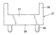
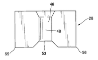
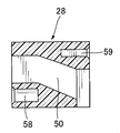
図8は前記ガイドプレート28を基端側から見た正面図であり、図9はその平面図、図10はその背面図、図11は図8のC−C断面図である。前記ガイドプレート28には、それらの図8〜図11によく示されているように、上面及び下面側からそれぞれ上側溝部46、下側溝部47が形成され、前記上側溝部46と前記下側溝部47とは水平隔壁48により分離されている。また、前記ガイドプレート28には、右側面及び左側面からそれぞれ右側溝部49、左側溝部50が形成され、前記右側溝部49と前記上側及び下側溝部46,47とは右側垂直隔壁51により分離され、前記左側溝部50と前記上側及び下側溝部46,47とは左側垂直隔壁52により分離されている。すなわち、前記上側溝部46、下側溝部47、右側溝部49、及び左側溝部50はそれぞれ、前記水平隔壁48、右側垂直隔壁51、及び左側垂直隔壁52により上下左右に分離されるようになっており、前記右側溝部49と前記左側溝部50間の距離は、前記上側溝部46と前記下側溝部47間の距離に比べて大きく離れている。さらに、前記水平隔壁48の先端側の上側及び下側角部53,54(図2参照)、及び前記右側及び左側垂直隔壁51,52の先端側の外側角部55,56(図3参照)はそれぞれ、前記各ツイストペア線22A,22B,22C,22Dを前記整列部材27になるべく近い位置で前記絶縁ハウジング26の内面側に押し広げ、該絶縁ハウジング26内の空間57一杯に広げるように形成されている。なお、前記水平隔壁48及び前記各垂直隔壁51,52の厚みを変更することにより、前記各ツイストぺエア線22A,22B,22C,22Dを前記絶縁ハウジング26の内面側に押し付ける度合いを調整できるようになっている。また、前記ガイドプレート28には、先端側下部の両側に丸溝58が形成され、基端側上部の両側に角溝59が形成されている。なお、この例では、前記右側及び左側溝部49,50は先端方向に向かって上方に傾斜して形成されているが、水平に形成されていてもよい。
【0027】
前記クランプ金具29は、コの字状のハウジング固定部60と、該ハウジング固定部60の基端側に設けられたU字状のケーブル固定部61とから構成されている。前記ハウジング固定部60には、基端方向に向かって前記角溝59に係合可能な係合突起62が延出し、さらに、下面に前記係止突起36が係止可能な係止凹部63が形成されている。
【0028】
次に、前記モジュラープラグ21の組立て手順を説明する。
【0029】
先ず、前記係合突起62を前記角溝59に係合させ、前記クランプ金具29を前記ガイドプレート28に連結し、前記クランプ金具29のケーブル固定部61でクランプすることにより、前記ケーブル23を保持する。そして、前記4組のツイストペア線22A,22B,22C,22Dを撚った状態のまま前記ガイドプレート28の左右溝部50,49と上下溝部46,47により分離させ、且つ、前記ツイストペア線22A,22B,22C,22Dを前記整列部材27の拡幅部45に保持させると共に、その先端部の撚りを解かれた前記8本の電線24a,24a’,24b,24c,24c’,24b’,24d,24d’を前記整列部材27の貫通孔41の各丸孔42a,42b,42c,42d,42e,42f,42g,42hにそれぞれ挿通させ、保持させる。このように、前記各ツイストペア線22A,22B,22C,22Dは前記貫通孔41の直近まで撚りを解かない状態で前記拡幅部45により保持されるので、近端クロストークを低減することができる。
【0030】
前記整列部材27のツイストペア線保持部39に前記ツイストペア線22A,22B,22C,22Dを保持させた状態で、基端側から前記整列部材27の位置決め突起40に前記ガイドプレート28の丸溝58を嵌合し、該ガイドプレート28を前記整列部材27に連結する。そして、前記4組のツイストペア線22A,22B,22C,22Dを前記右側溝部49、上側溝部46、下側溝部47、左側溝部50にそれぞれ嵌設させると、前記ツイストペア線22A,22B,22C,22Dは前記外側角部55、上側角部53、下側角部54、外側角部56により前記整列部材27になるべく近い位置でそれぞれ前記絶縁ハウジング26の内面側に押し広げられ、前記空間57一杯に広げられる。これにより、前記各ツイストペア線22A,22B,22C,22Dは前記水平隔壁48、右側及び左側垂直隔壁51,52によりそれぞれお互いから分離されると共に離間されるので、近端クロストークの減衰量を所定範囲内に保持することができる。
【0031】
その後、このように前記4組のツイストペア線22A,22B,22C,22Dを保持した前記整列部材27及びガイドプレート28を、前記クランプ金具29と共に前記絶縁ハウジング26の嵌合凹部25内に挿入し、前記係止突起36を前記係止凹部63に係止させることにより前記絶縁ハウジング26に固定する。そして、前記スリット孔33を介して下方から前記各端子30,31を挿入し、前記各電線24a,24a’,24b,24b’,24c,24c’,24d,24d’に接続する。この時、前記上段の丸孔42c,42d,42e,42fに保持された電線24b,24c,24c’,24b’に対しては長い端子30を使用し、前記下段の丸孔42a,42b,42g,42hに保持された電線24a,24a’,24d,24d’に対しては短い端子31を使用する。
【0032】
なお、前記各丸孔42a,42b,42c,42d,42e,42f,42g,42hの配置は、上記した配置に限定されるものではなく、各種の変更が可能である。例えば、図12〜図15に示されているように、丸孔42a,42c,42d,42e,42f,42hを上段とし、丸孔42b、42gを下段とする配置(図12参照)、丸孔42a,42b,42g,42hを上段とし、丸孔42c,429d,42e,42fを下段とする配置(図13参照)、丸孔42b,42gを上段とし、丸孔42a,42c,42d,42e,42f,42hを下段とする配置(図14参照)、或いは、前記丸孔を3段に渡って設け、丸孔42bを上段、丸孔42a,42c,42d,42e,42f,42hを中段とし、丸孔42gを下段とする配置(図15参照)等、他の配置としてもよい。そして、このように前記各丸孔の配置を変更した場合、前記整列部材27には前記各丸孔の配置に対応した貫通孔が穿設される。
【0033】
また、上記説明では、4組のツイストペア線22A,22B,22C,22Dからなるケーブル23を結線する場合について説明したが、本発明は、2組、3組又は5組以上のツイストペア線を結線する場合においても実施可能であることは言う迄もない。
【0034】
【発明の効果】
以上述べた如く本発明によれば、各ツイストペア線をガイドプレートにより分離させると共にハウジングの内面とガイドプレートとの間に収容することができ、電線の保持位置の直近まで撚りを解かない状態でツイストペア線を保持することができるので、近接クロストークを確実に低減でき、その減衰量を所定範囲内に保つことができる。
【図面の簡単な説明】
【図1】本発明の実施の形態に係るモジュラープラグを示す斜視図である。
【図2】本発明の実施の形態を示す断面図である。
【図3】図2のA−A断面図である。
【図4】本発明の実施の形態における整列部材を示す正面図である。
【図5】本発明の実施の形態における整列部材を示す平面図である。
【図6】図4のB−B断面図である。
【図7】本発明の実施の形態に係るモジュラープラグの正面図である。
【図8】本発明の実施の形態におけるガイドプレートを示す正面図である。
【図9】本発明の実施の形態におけるガイドプレートを示す平面図である。
【図10】本発明の実施の形態におけるガイドプレートを示す背面図である。
【図11】図8のC−C断面図である。
【図12】本発明の実施の形態における整列部材の丸孔の他の配置例を示す正面図である。
【図13】本発明の実施の形態における整列部材の丸孔の他の配置例を示す正面図である。
【図14】本発明の実施の形態における整列部材の丸孔の他の配置例を示す正面図である。
【図15】本発明の実施の形態における整列部材の丸孔の他の配置例を示す正面図である。
【図16】従来例を示す斜視図である。
【図17】従来例を示す破断面図である。
【符号の説明】
21 モジュラープラグ
22 ツイストペア線
24 電線
26 絶縁ハウジング
27 整列部材
28 ガイドプレート
30 端子
31 端子
41 貫通孔
45 拡幅部
48 水平隔壁
51 右側垂直隔壁
52 左側垂直隔壁
57 空間[0001]
BACKGROUND OF THE INVENTION
The present invention relates to a modular plug that fits into a modular jack, and more particularly to a modular plug for connecting twisted pair wires formed by twisting two electric wires.
[0002]
[Prior art]
In general, modular jacks and modular plugs are known as connector members used in telephone facilities and LANs (local area networks). Among these, the modular plug is a member that fits into a modular jack and connects a plurality of electric wires such as cables, and the conventional modular plug is disclosed in, for example, JP-A-10-134903. There is.
[0003]
As shown in FIGS. 16 and 17, the
[0004]
The
[0005]
In such a configuration, to assemble the
[0006]
[Problems to be solved by the invention]
In general, modular plugs are required to reduce so-called crosstalk in order to prevent noise and other troubles. In recent years, in particular, the demand for near-end crosstalk (NEXT) attenuation has become stricter. ing. However, the above-described conventional
[0007]
Therefore, the present invention seeks to provide a modular plug that can meet the demand for such severe near-end crosstalk attenuation.
[0008]
[Means for Solving the Problems]
The present invention relates to a modular plug for fitting a modular jack and connecting twisted pair wires, a housing; and a guide plate that is fitted in the housing and separates a plurality of sets of the twisted pair wires for each set. And 8 wires, which are fitted in the housing while being connected to the guide plate, and untwisted at the ends of the first to fourth four pairs of twisted pair wires are aligned and held in a plurality of stages. An alignment member having a through-hole continuously provided in the lateral direction, and the alignment member into which all of the eight electric wires are inserted into the continuous through-hole; and a tip portion of each twisted pair wire Each of which is connected to the untwisted wire, and the twisted pair wires separated for each set are accommodated between the inner surface of the housing and the guide plate without untwisting. Constructed and as; the said guide plate, vertically and horizontally, the upper groove portion, the lower groove portion, the right groove, and the left groove is formed, the lower groove portion and the upper groove portion of the guide plate The right groove and the upper and lower grooves are separated by a right vertical partition, and the left groove and the upper and lower grooves are vertically separated by a horizontal partition having a certain thickness along the direction of fitting to the housing. The partition wall separates the distance between the right groove portion and the left groove portion so as to be constant along the direction in which the guide plate is fitted to the housing ; the upper and lower tip sides of the horizontal partition wall corners, state the distal-side corner portion of the right vertical partition wall, and that the distal end corners of the left vertical partition wall, by twisting the respective twisted pair lines until it contacts the inner surface of the housing Mom that are spread on the inner surface side is formed so as to widen the space filled in said housing, said right slot and left grooves, respectively, the upwardly inclined toward the distal end, located outside The first and fourth twisted pair wires are directed upward to the corresponding through-holes of the alignment member; the through-holes are arranged in the lower stage of the first and fourth twisted-pair wires . is widened portion which is widened by the inclined surface on the base end side of the through hole is formed; the wires of the second and third twisted pair wires formed has to be arranged in the upper stage disposed inside cage, the wider section, in the base end side of the through hole, Ri holdable der without solving the twisting said twisted pair line to the nearest of the through hole, and the widened portion, the second and third twisted wire pair Each wire The alignment member is inclined so as to narrow toward the distal end so as to be guided to the upper stage of the corresponding through hole of the alignment member, and the electric wires of the first and fourth twisted pair wires are connected to the corresponding through hole of the alignment member. to guide the lower, it characterized that you have inclined to narrow toward the front end direction.
The widened portion is inclined so as to narrow toward the front end only at the lower side so as to guide the electric wires of the second and third twisted pair wires to the upper stage of the corresponding through hole of the alignment member. In addition, each of the electric wires of the first and fourth twisted pair wires is inclined so as to narrow toward the distal end both above and below so as to be guided to the lower stage of the corresponding through hole of the alignment member. May be.
[0009]
Preferably, the guide plate is formed with grooves on the top, bottom, left and right, and each groove is separated by a partition.
[0010]
The partition is formed so as to spread each twisted pair wire toward the inner surface of the housing.
[0011]
Further, the partition wall is formed so as to spread each twisted pair wire toward the inner surface side of the housing by a corner portion on the front end side.
[0012]
The present invention also relates to a modular plug for fitting into a modular jack and connecting a twisted pair wire, the housing, and a distal end portion of the first to fourth four twisted pair wires fitted in the housing. An alignment member having a through-hole for aligning and holding eight untwisted electric wires in a plurality of upper and lower stages, and eight terminals connected to the untwisted electric wires at the tip of each twisted pair wire, And the through holes are arranged in different stages, the electric wires inside the first twisted pair wires and the electric wires inside the second twisted pair wires, and the electric wires inside the third twisted pair wires and the inner wires of the fourth twisted pair wires, respectively. The electric wires of the second and third twisted pair wires are formed so as to be arranged in the same stage.
[0013]
Preferably, the base end side of the through hole is formed with a widened portion capable of holding the twisted pair wires up to the vicinity of the through hole without untwisting.
[0014]
Furthermore, the present invention relates to a modular plug for fitting into a modular jack to connect a twisted pair wire, the housing, and a distal end portion of four first to fourth pairs of twisted pair wires fitted in the housing. An alignment member having a through-hole for aligning and holding the eight untwisted electric wires in a plurality of upper and lower stages, and a base end side of the alignment member in the housing. A guide plate that is separated for each pair; and eight terminals that are respectively connected to eight wires that have been untwisted at the tip of each twisted pair wire, and each of the through holes is adjacent to the first twisted pair. An electric wire inside the wire and an electric wire of the second twisted pair wire, and an electric wire of the third twisted pair wire and an electric wire inside the fourth twisted pair wire are arranged in different stages, and the second and third twisted wires Each wire of the wire is formed so as to be arranged side by side in the same step, and the four pairs of twisted pair wires are respectively accommodated between the inner surface of the housing and the guide plate. It is characterized by.
[0015]
Further, the guide plate is formed with grooves on the top, bottom, left and right, and each groove is separated by a partition.
[0016]
Further, the partition wall is formed so as to spread each twisted pair wire toward the inner surface side of the housing.
[0017]
Further, the partition wall is formed so as to spread each twisted pair wire toward the inner surface side of the housing by the corner portion on the front end side.
[0019]
With such a configuration, near-end crosstalk can be reduced, and the amount of attenuation can be maintained within a predetermined range.
[0020]
DETAILED DESCRIPTION OF THE INVENTION
Hereinafter, embodiments of the present invention will be described with reference to the drawings.
[0021]
1 to 15 show an example of a modular plug according to an embodiment of the present invention. In this example, the
[0022]
The
[0023]
At the distal end portion of the insulating
[0024]
4 is a front view of the
[0025]
Further, the base end side of the through
[0026]
8 is a front view of the
[0027]
The clamp fitting 29 includes a U-shaped
[0028]
Next, the assembly procedure of the
[0029]
First, the engagement protrusion 62 is engaged with the
[0030]
With the twisted pair
[0031]
Thereafter, the
[0032]
The arrangement of the
[0033]
In the above description, the case where the
[0034]
【The invention's effect】
As described above, according to the present invention, each twisted pair wire can be separated by the guide plate and can be accommodated between the inner surface of the housing and the guide plate, and the twisted pair can be untwisted until the position near the holding position of the electric wire. Since the line can be held, proximity crosstalk can be reliably reduced, and the attenuation can be kept within a predetermined range.
[Brief description of the drawings]
FIG. 1 is a perspective view showing a modular plug according to an embodiment of the present invention.
FIG. 2 is a cross-sectional view showing an embodiment of the present invention.
3 is a cross-sectional view taken along the line AA in FIG.
FIG. 4 is a front view showing the alignment member in the embodiment of the present invention.
FIG. 5 is a plan view showing an alignment member in the embodiment of the present invention.
6 is a cross-sectional view taken along the line BB in FIG.
FIG. 7 is a front view of the modular plug according to the embodiment of the present invention.
FIG. 8 is a front view showing a guide plate in the embodiment of the present invention.
FIG. 9 is a plan view showing a guide plate in the embodiment of the present invention.
FIG. 10 is a rear view showing the guide plate in the embodiment of the present invention.
FIG. 11 is a cross-sectional view taken along the line CC of FIG.
FIG. 12 is a front view showing another arrangement example of the round holes of the alignment member in the embodiment of the present invention.
FIG. 13 is a front view showing another arrangement example of the round holes of the alignment member in the embodiment of the present invention.
FIG. 14 is a front view showing another arrangement example of the round holes of the alignment member in the embodiment of the present invention.
FIG. 15 is a front view showing another arrangement example of the round holes of the alignment member in the embodiment of the present invention.
FIG. 16 is a perspective view showing a conventional example.
FIG. 17 is a broken sectional view showing a conventional example.
[Explanation of symbols]
21 Modular plug 22 Twisted pair wire 24
Claims (2)
ハウジングと、
該ハウジング内に嵌設され、複数組の前記ツイストペア線を各組毎に分離させるガイドプレートと、
前記ガイドプレートと連結された状態で前記ハウジング内に嵌設され、第1から第4の4組のツイストペア線の先端部の撚りを解かれた8本の電線を上下複数段に整列保持する横方向に連設された貫通孔を有する整列部材であって、該連設された貫通孔に前記8本の電線の全てが挿入される、前記整列部材と、
前記各ツイストペア線の先端部の撚りを解かれた電線にそれぞれ接続される端子と、
を備え、
前記各組毎に分離されたツイストペア線が前記ハウジングの内面と前記ガイドプレートとの間に撚りを解かずに収容されるように構成されており、
前記ガイドプレートには、上下左右に、上側溝部、下側溝部、右側溝部、及び左側溝部が形成され、前記上側溝部と前記下側溝部は前記ガイドプレートの前記ハウジングに対する嵌設の方向に沿って一定の厚みを有する水平隔壁により分離され、前記右側溝部と前記上側及び下側溝部は右側垂直隔壁により、前記左側溝部と前記上側及び下側溝部は左側垂直隔壁により、前記右側溝部と前記左側溝部の間の距離が前記ガイドプレートの前記ハウジングに対する嵌設の方向に沿って一定となるように分離されており、
前記水平隔壁の上側及び下側の先端側角部、前記右側垂直隔壁の先端側角部、及び前記左側垂直隔壁の先端側角部により、前記ハウジングの内面に接触するまで前記各ツイストペア線を撚った状態のままその内面側に押し広げて前記ハウジング内の空間一杯に広げるように形成されており、前記右側溝部及び左側溝部は、それぞれ、先端方向に向かって上方に傾斜して、外側に配置された第1及び第4ツイストペア線の各電線を上方へ向けて前記整列部材の対応する貫通孔に案内しており、
前記貫通孔は、前記第1及び第4ツイストペア線の各電線が下段に配置され、内側に配置された第2及び第3ツイストペア線の各電線が上段に並んで配置されるように形成されており、
前記貫通孔の基端側に傾斜面によって拡幅された拡幅部が形成されており、前記拡幅部は、前記貫通孔の基端側において、前記ツイストペア線を前記貫通孔の直近まで撚りを解かずに保持可能であり、前記拡幅部は、前記第2及び第3ツイストペア線の各電線を前記整列部材の対応する貫通孔の上段に案内するように、先端方向に向かって狭まるように傾斜しており、また、前記第1及び第4ツイストペア線の各電線を前記整列部材の対応する貫通孔の下段に案内するように、先端方向に向かって狭まるように傾斜していることを特徴とするモジュラープラグ。A modular plug that fits into a modular jack and connects a twisted pair wire,
A housing;
A guide plate that is fitted in the housing and separates a plurality of sets of the twisted pair wires for each set;
A horizontal line that holds eight electric wires, which are fitted in the housing in a state of being connected to the guide plate, and untwisted at the tip ends of the first to fourth four pairs of twisted pairs, in a plurality of stages. An alignment member having through-holes continuously provided in a direction, wherein all of the eight electric wires are inserted into the through-holes provided continuously;
Terminals connected to the untwisted wires at the tip of each twisted pair wire,
With
The twisted pair wires separated for each set are configured to be accommodated without untwisting between the inner surface of the housing and the guide plate,
The guide plate is formed with an upper groove portion, a lower groove portion, a right groove portion, and a left groove portion in the upper , lower, left and right directions , and the upper groove portion and the lower groove portion are arranged in a direction in which the guide plate is fitted to the housing. The right and left upper grooves are separated by a right vertical partition, the left and upper and lower grooves are separated by a left vertical partition, the right groove and the right groove. The distance between the left groove portions is separated so as to be constant along the direction of fitting the guide plate to the housing ,
The twisted pair wires are twisted until they come into contact with the inner surface of the housing by the upper and lower tip corners of the horizontal partition, the tip vertical corner of the right vertical partition, and the tip corner of the left vertical partition. In this state, it is formed so as to be spread to the inner surface side to expand to the full space in the housing, and the right groove portion and the left groove portion are inclined upward toward the distal end, respectively, Each of the arranged first and fourth twisted pair wires is directed upward to the corresponding through hole of the alignment member;
The through hole is formed such that the electric wires of the first and fourth twisted pair wires are arranged in the lower stage, and the electric wires of the second and third twisted pair wires arranged in the inner side are arranged in the upper stage. And
Wherein is widened portion which is widened is formed by the inclined surface on the base end side of the through hole, and the widened portion, in the base end side of the through hole, without solving the twisting said twisted pair line to the nearest of the through hole holdable der is, the wider section has a respective wire of the second and third twisted pair line to guide the upper part of the corresponding through hole of the alignment member, inclined so as to narrow toward the front end direction and which, also, the respective wires of the first and fourth twisted wire pair to guide the lower part of the corresponding through hole of the alignment member, characterized that you have inclined such narrows toward the distal end Modular plug.
Priority Applications (4)
| Application Number | Priority Date | Filing Date | Title |
|---|---|---|---|
| JP2002185921A JP4199961B2 (en) | 2002-06-26 | 2002-06-26 | Modular plug |
| US10/464,040 US6846197B2 (en) | 2002-06-26 | 2003-06-18 | Modular plug |
| DE60301521T DE60301521T2 (en) | 2002-06-26 | 2003-06-25 | Modular plug |
| EP03013481A EP1376779B1 (en) | 2002-06-26 | 2003-06-25 | Modular plug |
Applications Claiming Priority (1)
| Application Number | Priority Date | Filing Date | Title |
|---|---|---|---|
| JP2002185921A JP4199961B2 (en) | 2002-06-26 | 2002-06-26 | Modular plug |
Publications (3)
| Publication Number | Publication Date |
|---|---|
| JP2004031130A JP2004031130A (en) | 2004-01-29 |
| JP2004031130A5 JP2004031130A5 (en) | 2005-03-17 |
| JP4199961B2 true JP4199961B2 (en) | 2008-12-24 |
Family
ID=29717613
Family Applications (1)
| Application Number | Title | Priority Date | Filing Date |
|---|---|---|---|
| JP2002185921A Expired - Fee Related JP4199961B2 (en) | 2002-06-26 | 2002-06-26 | Modular plug |
Country Status (4)
| Country | Link |
|---|---|
| US (1) | US6846197B2 (en) |
| EP (1) | EP1376779B1 (en) |
| JP (1) | JP4199961B2 (en) |
| DE (1) | DE60301521T2 (en) |
Cited By (1)
| Publication number | Priority date | Publication date | Assignee | Title |
|---|---|---|---|---|
| JP2013051116A (en) * | 2011-08-31 | 2013-03-14 | Yazaki Corp | Connector structure and twisted wire |
Families Citing this family (12)
| Publication number | Priority date | Publication date | Assignee | Title |
|---|---|---|---|---|
| US7150657B2 (en) * | 2003-05-23 | 2006-12-19 | Nordx/Cdt Inc. | Wire lead guide and method for terminating a communications cable |
| US7175468B1 (en) * | 2006-06-06 | 2007-02-13 | Telebox Industries Corp. | Plug for the transmission of high frequency/telecommunication signals |
| US7361047B2 (en) * | 2006-09-01 | 2008-04-22 | Michael Strahl | Replacement depressible tab for modular telecommunications plug |
| US7540756B1 (en) | 2008-01-25 | 2009-06-02 | Michael Strahl | Replacement depressible tab for modular telecommunications plug |
| US8993887B2 (en) * | 2009-11-09 | 2015-03-31 | L-Com, Inc. | Right angle twisted pair connector |
| US8702444B2 (en) | 2010-10-18 | 2014-04-22 | Panduit Corp. | Communication plug with improved cable manager |
| CN103545663B (en) * | 2012-07-12 | 2016-06-08 | 富士康(昆山)电脑接插件有限公司 | RJ pin connector |
| US8979553B2 (en) * | 2012-10-25 | 2015-03-17 | Molex Incorporated | Connector guide for orienting wires for termination |
| WO2014144735A1 (en) * | 2013-03-15 | 2014-09-18 | Tyco Electronics Uk Ltd. | Connector with capacitive crosstalk compensation to reduce alien crosstalk |
| CN107925195B (en) | 2015-08-12 | 2020-03-13 | 康普技术有限责任公司 | Electric plug connector |
| EP3595099B1 (en) * | 2018-07-13 | 2021-09-01 | Rosenberger Hochfrequenztechnik GmbH & Co. KG | Conductor crosser |
| JP6955133B1 (en) * | 2020-03-03 | 2021-10-27 | 昭和電線ケーブルシステム株式会社 | Cable with round connector and its manufacturing method |
Family Cites Families (13)
| Publication number | Priority date | Publication date | Assignee | Title |
|---|---|---|---|---|
| US5601447A (en) * | 1995-06-28 | 1997-02-11 | Reed; Carl G. | Patch cord assembly |
| JP3212261B2 (en) | 1996-11-05 | 2001-09-25 | ヒロセ電機株式会社 | Modular plug |
| US5899770A (en) | 1996-11-05 | 1999-05-04 | Hirose Electric Co., Ltd. | Modular plug and modular jack |
| US6007368A (en) * | 1997-11-18 | 1999-12-28 | Leviton Manufacturing Company, Inc. | Telecommunications connector with improved crosstalk reduction |
| US6599148B1 (en) * | 1998-04-24 | 2003-07-29 | Cekan/Cdt A/S | Strain relieved leading-in connection for signal cables with twisted wire pairs |
| US6099345A (en) * | 1999-04-23 | 2000-08-08 | Hubbell Incorporated | Wire spacers for connecting cables to connectors |
| US6123572A (en) * | 1999-10-15 | 2000-09-26 | Toshiki Tamura | Modular plug for a signal transmission cable |
| DE19959823C2 (en) | 1999-12-10 | 2003-04-30 | Krone Gmbh | Connection cable with electrical plug connection |
| JP3708785B2 (en) * | 2000-03-23 | 2005-10-19 | ヒロセ電機株式会社 | Modular plug and harness products |
| US6524128B2 (en) | 2000-06-02 | 2003-02-25 | Stewart Connector Systems, Inc. | Modular plug wire aligner |
| US6406325B1 (en) * | 2000-12-28 | 2002-06-18 | Surtec Industries Inc. | Connector plug for network cabling |
| US6409544B1 (en) * | 2001-05-23 | 2002-06-25 | Lorom Industrial Co., Ltd. | Network data transmission cable connector |
| US6439920B1 (en) * | 2001-09-18 | 2002-08-27 | Surtec Industries Inc. | Electronic connector plug for high speed transmission |
-
2002
- 2002-06-26 JP JP2002185921A patent/JP4199961B2/en not_active Expired - Fee Related
-
2003
- 2003-06-18 US US10/464,040 patent/US6846197B2/en not_active Expired - Fee Related
- 2003-06-25 DE DE60301521T patent/DE60301521T2/en not_active Expired - Fee Related
- 2003-06-25 EP EP03013481A patent/EP1376779B1/en not_active Expired - Fee Related
Cited By (1)
| Publication number | Priority date | Publication date | Assignee | Title |
|---|---|---|---|---|
| JP2013051116A (en) * | 2011-08-31 | 2013-03-14 | Yazaki Corp | Connector structure and twisted wire |
Also Published As
| Publication number | Publication date |
|---|---|
| EP1376779A1 (en) | 2004-01-02 |
| DE60301521D1 (en) | 2005-10-13 |
| US6846197B2 (en) | 2005-01-25 |
| JP2004031130A (en) | 2004-01-29 |
| EP1376779B1 (en) | 2005-09-07 |
| DE60301521T2 (en) | 2006-06-14 |
| US20040002252A1 (en) | 2004-01-01 |
Similar Documents
| Publication | Publication Date | Title |
|---|---|---|
| US5885111A (en) | Keystone jack for digital communication networks | |
| JP4219279B2 (en) | Modular plug for use at the end of the cable | |
| US5879199A (en) | Modular jack assembly and universal housing for use therein | |
| US6083052A (en) | Enhanced performance connector | |
| JP4199961B2 (en) | Modular plug | |
| US7448920B2 (en) | Wire lead guide and method for terminating a communications cable | |
| US7811118B2 (en) | Wire containment cap | |
| JP3120378B2 (en) | Electrical connector with shutter | |
| JPH08106944A (en) | Electric connector and housing of this electric connector | |
| US20120270449A1 (en) | Wire Containment Cap | |
| KR100668189B1 (en) | Connecting cable comprising an electric plug-and-socket connection | |
| JP2003522389A (en) | Vertical and right angle modular outlets | |
| JP2002508882A (en) | High-speed IDC modular jack | |
| JP2001267023A (en) | Modular plug and harness product | |
| RU2403660C2 (en) | Plug | |
| US6390851B1 (en) | Electrical connector with internal shield | |
| KR100335220B1 (en) | Structure for preventing noise of connector pin | |
| KR200197422Y1 (en) | Structure for preventing noise of connector pin | |
| KR100375709B1 (en) | Modular plug |
Legal Events
| Date | Code | Title | Description |
|---|---|---|---|
| A521 | Request for written amendment filed |
Free format text: JAPANESE INTERMEDIATE CODE: A523 Effective date: 20040420 |
|
| A621 | Written request for application examination |
Free format text: JAPANESE INTERMEDIATE CODE: A621 Effective date: 20040420 |
|
| A977 | Report on retrieval |
Free format text: JAPANESE INTERMEDIATE CODE: A971007 Effective date: 20050720 |
|
| A131 | Notification of reasons for refusal |
Free format text: JAPANESE INTERMEDIATE CODE: A131 Effective date: 20050801 |
|
| A521 | Request for written amendment filed |
Free format text: JAPANESE INTERMEDIATE CODE: A523 Effective date: 20050915 |
|
| A02 | Decision of refusal |
Free format text: JAPANESE INTERMEDIATE CODE: A02 Effective date: 20060320 |
|
| A521 | Request for written amendment filed |
Free format text: JAPANESE INTERMEDIATE CODE: A523 Effective date: 20060516 |
|
| A521 | Request for written amendment filed |
Free format text: JAPANESE INTERMEDIATE CODE: A821 Effective date: 20060419 |
|
| A911 | Transfer to examiner for re-examination before appeal (zenchi) |
Free format text: JAPANESE INTERMEDIATE CODE: A911 Effective date: 20060525 |
|
| A912 | Re-examination (zenchi) completed and case transferred to appeal board |
Free format text: JAPANESE INTERMEDIATE CODE: A912 Effective date: 20060901 |
|
| A521 | Request for written amendment filed |
Free format text: JAPANESE INTERMEDIATE CODE: A523 Effective date: 20080821 |
|
| A01 | Written decision to grant a patent or to grant a registration (utility model) |
Free format text: JAPANESE INTERMEDIATE CODE: A01 |
|
| A61 | First payment of annual fees (during grant procedure) |
Free format text: JAPANESE INTERMEDIATE CODE: A61 Effective date: 20081006 |
|
| FPAY | Renewal fee payment (event date is renewal date of database) |
Free format text: PAYMENT UNTIL: 20111010 Year of fee payment: 3 |
|
| R150 | Certificate of patent or registration of utility model |
Ref document number: 4199961 Country of ref document: JP Free format text: JAPANESE INTERMEDIATE CODE: R150 Free format text: JAPANESE INTERMEDIATE CODE: R150 |
|
| FPAY | Renewal fee payment (event date is renewal date of database) |
Free format text: PAYMENT UNTIL: 20111010 Year of fee payment: 3 |
|
| FPAY | Renewal fee payment (event date is renewal date of database) |
Free format text: PAYMENT UNTIL: 20121010 Year of fee payment: 4 |
|
| R250 | Receipt of annual fees |
Free format text: JAPANESE INTERMEDIATE CODE: R250 |
|
| FPAY | Renewal fee payment (event date is renewal date of database) |
Free format text: PAYMENT UNTIL: 20121010 Year of fee payment: 4 |
|
| FPAY | Renewal fee payment (event date is renewal date of database) |
Free format text: PAYMENT UNTIL: 20131010 Year of fee payment: 5 |
|
| R250 | Receipt of annual fees |
Free format text: JAPANESE INTERMEDIATE CODE: R250 |
|
| S111 | Request for change of ownership or part of ownership |
Free format text: JAPANESE INTERMEDIATE CODE: R313115 |
|
| S531 | Written request for registration of change of domicile |
Free format text: JAPANESE INTERMEDIATE CODE: R313531 |
|
| S111 | Request for change of ownership or part of ownership |
Free format text: JAPANESE INTERMEDIATE CODE: R313117 |
|
| R371 | Transfer withdrawn |
Free format text: JAPANESE INTERMEDIATE CODE: R371 |
|
| R250 | Receipt of annual fees |
Free format text: JAPANESE INTERMEDIATE CODE: R250 |
|
| R371 | Transfer withdrawn |
Free format text: JAPANESE INTERMEDIATE CODE: R371 |
|
| S111 | Request for change of ownership or part of ownership |
Free format text: JAPANESE INTERMEDIATE CODE: R313115 |
|
| R350 | Written notification of registration of transfer |
Free format text: JAPANESE INTERMEDIATE CODE: R350 |
|
| S111 | Request for change of ownership or part of ownership |
Free format text: JAPANESE INTERMEDIATE CODE: R313117 |
|
| R350 | Written notification of registration of transfer |
Free format text: JAPANESE INTERMEDIATE CODE: R350 |
|
| LAPS | Cancellation because of no payment of annual fees |