JP4195505B2 - 3D image detector using wavelength-shifted optical fiber - Google Patents
3D image detector using wavelength-shifted optical fiber Download PDFInfo
- Publication number
- JP4195505B2 JP4195505B2 JP52916695A JP52916695A JP4195505B2 JP 4195505 B2 JP4195505 B2 JP 4195505B2 JP 52916695 A JP52916695 A JP 52916695A JP 52916695 A JP52916695 A JP 52916695A JP 4195505 B2 JP4195505 B2 JP 4195505B2
- Authority
- JP
- Japan
- Prior art keywords
- light
- crystal
- radiation detector
- wavelength
- photosensor
- Prior art date
- Legal status (The legal status is an assumption and is not a legal conclusion. Google has not performed a legal analysis and makes no representation as to the accuracy of the status listed.)
- Expired - Fee Related
Links
Images


Classifications
-
- G—PHYSICS
- G01—MEASURING; TESTING
- G01T—MEASUREMENT OF NUCLEAR OR X-RADIATION
- G01T1/00—Measuring X-radiation, gamma radiation, corpuscular radiation, or cosmic radiation
- G01T1/16—Measuring radiation intensity
- G01T1/20—Measuring radiation intensity with scintillation detectors
-
- G—PHYSICS
- G01—MEASURING; TESTING
- G01T—MEASUREMENT OF NUCLEAR OR X-RADIATION
- G01T1/00—Measuring X-radiation, gamma radiation, corpuscular radiation, or cosmic radiation
- G01T1/16—Measuring radiation intensity
- G01T1/20—Measuring radiation intensity with scintillation detectors
- G01T1/202—Measuring radiation intensity with scintillation detectors the detector being a crystal
Landscapes
- High Energy & Nuclear Physics (AREA)
- Spectroscopy & Molecular Physics (AREA)
- Physics & Mathematics (AREA)
- Health & Medical Sciences (AREA)
- Life Sciences & Earth Sciences (AREA)
- General Physics & Mathematics (AREA)
- Molecular Biology (AREA)
- Chemical & Material Sciences (AREA)
- Crystallography & Structural Chemistry (AREA)
- Measurement Of Radiation (AREA)
- Nuclear Medicine (AREA)
- Lasers (AREA)
- Length Measuring Devices By Optical Means (AREA)
- Spectrometry And Color Measurement (AREA)
Abstract
Description
発明の分野
本発明は、一般的には、イオン化放射の検出及び映像化のための装置及び技術、そして特に、波長シフト光ファイバに結合された光発生クリスタルを使用するガンマ線検出器に関する。
発明の背景
現在の細胞核医学は、患者内で生じる内部身体構成及びバイオケミカルプロセスの非侵入診断のための種々の技術を提供する。コンピュータ化軸方向断層写真(CAT)、核磁気共鳴映像(MRI)スキャン及び通常のX線法が、このような構造映像化システムの例である。身体構造のみを識別しかつ特定するこれらの技術は、異常が現れかつ検出される時までに、このような異常を生じる病理学状態がしばしばかなり進むという障害がある。
これに対し、陽電子放射断層写真(PET)システムは、脳内の機能する新陳代謝系と共に身体のその他の部分を映像化するために使用される。構造よりもむしろ機能を映像化することによって、これらのシステムは、X線,CAT、及びMRIシステムを独特に補って完全なものにする。PETは、同時発生の対になったガンマ線の検出を通して達成される。これらのガンマ線は、(典型的には患者の身体内に置かれる)ソースから発する陽電子が、ソース位置を取り巻く組織内の電子によって消滅するときに発生する。ガンマ線がこの消滅で発生するとき、これらの亜原子粒子の物理特性、及び他の公知の特性によって、二つのガンマ線は単一エネルギーで発することになる。この公知の特性は、例えば、ガンマ線は相互にほとんど反対の方向に進むように発するということである。
PET映像プロセスは多数のステップを包含している。陽子に富んだ放射性同位体が、患者の身体内に、例えば注射又は摂取によって、最初に置かれる。大部分の場合、これらの同位体は、診断が望まれるエリアに、又はその近くに集中される。身体内にいったん組み入れられると、この同位体は、自然発生崩壊プロセスの一部として陽電子を発し続ける。陽電子は、短い距離を移動した後、取り巻く組織からの電子と結合しかつ消滅する反電子である。消滅の時、ひとかたまりになった電子と陽電子の両方が、電磁放射に変換される。エネルギー及び線形運動量を保存するために、電磁放射は、エネルギーが等しくかつ互いに略180°で発する2つのガンマ線形態である。陽電子放射体が、身体を通って動くとき、その量及び位置の両方を測定するために、PET装置内で外部から検出するのは、この消滅放射である。
放射性同位体が患者の身体を通って動きかつそれによって処理されるとき、その濃度は、断面グレースケール(白黒の階調表示)映像として測定しかつ表示することができる。この映像において、各ピクセル(画素)の強度は、身体内のその位置の放射性同位体の濃度に比例している。この種のいわゆる”運動学的”技術は、人間の身体内の血液の流れ、基質搬送及びバイオケミカル反応のような動的処理を診断しかつ分析するための最も強力な方法の一つであったし、同様にこれからもあり続けるであろう。
現存するPETシステムは、人間の脳又は胴の多数の断層写真映像を同時に記録しかつ処理することができる。さらに、2次元映像を形成することのできる平面状リング構成、又は3次元映像を達成する容積レイアウトのいずれかで、センサーを位置させることができる。この後者のレイアウトは、陽電子容積映像化(PVI)と呼ばれるけれども、このPVIを参照するときそれに対して”PET”という用語を使用する者もいる。PVIは、データを最初にPETデータとして処理し、後に平面状映像を組み合わせて、容積映像を形成するように設定することができる。或いは、PVIは、センサー位置で平面間同時発生を可能にしかつそれ故にこれらの同時発生検出を処理することによって達成することができる。これらのいずれかのシステムによって達成できる解像度は、最近1センチメータ以下に狭められ、かつ被検者内の放射能分布は数パーセント以内に評価することができる。
典型的PET据え付けにおいて、ガンマ線センサーのリングが、放射性同位体ソースの局部位置において患者を取り巻くように位置決めされている。この検出プロセスは、ガンマ線放出が互いに180°で生じるという事実、及びガンマ線が同時に発生するという事実の両方を利用する。患者の両側のセンサーによるガンマ線の同時検出は、2つのセンサーの中心を接続するライン上又はその近くに消滅位置を定める。もし単一の検出が行われるならば、消滅は典型的には、2つの検出器の間の容積又は平面の外側で発生したことになる。この場合、ソースは診断エリアの外側に位置しているので、いかなる事象も記録されない。
使用可能のPETシステムは典型的には、放射センサー及びその関連した回路、必要な映像化ソフトウエアを有する高速コンピュータ、及びセンサー及び他の入力データを記憶しかつ処理するための大容量メモリを含む前述のデータ取得サブシステムを包含している。映像を直ちに見るためのディスプレイシステムがまた典型的には備えられる。最後に、一般的には、相互作用処理のための手段及びユーザーによるシステム制御装置が包含される。
早くも1986年には、数十のサイクロトロンPET地域センターが、世界的な開発の下で動作していたし、その数は増え続けている。サイクロトロンPETセンターは典型的には、放射性同位体を生じるための加速器(通常小さな医療用サイクロトロン)、陽電子放出断層写真装置(PET)、及び短寿命生物学的放射線トレーサーの合成のための化学研究室から成る。米国において、多くのこのようなセンターが、大学設立の医療研究センターに見ることができる。現代の高解像度PET検出器のコストは、クリスタルのための約100,000ドル及び光センサー(典型的にはホト増倍器)のための約250,000ドルを含めて、100万ドル以上である。
PETは1970年代に最初に実現されて以来、それは引き続き改良されてきた。不幸にも、最新の高解像度PETシステムは、この技術の物理学によって課せられた固有の限界、或いはその限界近くで動作している。陽電子放出放射性同位体への患者の露光が制限されていることからの統計的制限があり、かつ陽電子レンジ及び消滅時の残余の運動量からソース位置が不鮮明になることから、映像解像度及び精度に限界がある。さらに、この固有の限界近くで動作するシステムは、かなり複雑であり、また非常に高価である。これは、一部には、所望の解像度を達成するために非常に多数のセンサー要素を必要とすることによるものである。
現在のPET検出技術はまた、より高い解像度が求められるとき、クリスタル幅の減少から生じる種々の不正確さの影響を受ける。これらの不正確さは、一般的には、”映像作り物”(imaging artifacts)と呼ばれる。このような作り物の一つは、放射状のぼやけであり、かつこれは、このシステムの軸から離れたソースからのクリスタル侵入から生じる。言い換えると、もし同時発生ラインが、検出器リングの直径からある距離の所に位置しているならば、ガンマ線は、検出クリスタルによって吸収される前に一つまたはいくつかのクリスタルを通して通過することができる。これは、次に、視界の端の方に同時発生開口機能を広げる。この問題は、クリスタル材料の減衰長さが増加するとき、さらに複雑化する。より長い減衰長を有するクリスタル材料を使うときに等価な効率を達成するために(ここで、このようなクリスタルは、さもなければ、高輝度、高速度、低コストのような所望の特性を有することができる)、対応してクリスタル深さは増さなければならない。しかし、いったんクリスタルが深くされると、放射状のぼやけは増加する。現在使用されている最短減衰長のクリスタルによってさえ、放射状のぼやけは、検出器の中心軸から数センチメータの対象のためにシステム解像度を制限する。この問題を解決するために、種々の提案がなされ、主要な解決策は、検出器内で相互作用するホトンのための相互作用深さの測定を用いることである。現代の映像システムは、ビスマスガーミネイトのような緻密な光発生クリスタルを使用することによって、非常に狭いクリスタルを使用することによって、そしてより大きなクリスタルにおいてガンマ線の相互作用の特別の位置を決定する特殊センサーを使用することによって、映像作り物を最小化する試みがなされてきた。非常に高い解像度のPET検出器において相互作用の深さを測定する多様な方法が提案されたが、しかし、このような測定法はすべて、(ホトダイオードのような)多くの追加のホトセンサーと関連したエレクトロニクス、或いは複雑な符号化構成のいずれかを必要とした。
臨床細胞核医療用途で使われる別の種類の映像装置は、単一ホトン放射コンピュータ化断層写真(SPECT)システムである。SPECTのために使用される検出器は、位置解像度要求が典型的にはずっと小さいけれども、PET検出器と多くの共通の属性を有している。SPECT映像プロセスにおいて、放射性トレーサーが注射又は摂取によって、最初に患者の身体内に置かれる。この放射性同位体は、それが患者の身体内を通って移動するとき、連続的に低エネルギーのガンマ線(ホトン)を放射することによって崩壊する。SPECT装置によって外部から検出するのは、このホトン放射である。SPECT装置によって検出されるホトン放射エネルギーは典型的には、PETシステムの消滅ガンマ線エネルギー(511keV)よりも低い、55−400keVの範囲内にある。広範に用いられる放射性核種は、テクニチウムの異性体、99mTc、であり、かつこれは、6時間の半減期(最初に存在した放射性核種の半分が崩壊するのに必要とする時間)を有している。99mTcの場合、この放射性核種は、ガンマ線を連続的に放射することによって崩壊し、かつそのガンマ線のエネルギーは140keVである。いくつかの共通に使用される同位元素が、崩壊ホトンエネルギー及び対応する身体の映像機能と共にここに挙げられている。
・ 201Tl、80keV;心臓及び胴の映像化のために使用。
・ 176Ta、55−65keV;心臓を映像化するために使用。
・ 133Xe,80keV;肺及び呼吸系研究のために使用。
普通のSPECT装置は、ガンマカメラ(クリスタル検出器)の直接前に置かれた数千の小さな穴が開けられた厚い鉛のシートから通常構成されるコリメータの使用を必要とする。一般的に、コリメータ穴は、クリスタル検出器に斜めに入射するホトンの通過を阻止し、それによって、入射ホトンの方向を選択するようにクリスタルに垂直である。患者の周りにガンマ線カメラ及び/又はコリメータを回転することによって、一連の2次元投射を、異なる方向から形成することができる。種々の再構成技術を適用することによって、放射性トレーサーの内部分布は、平行2次元横断面のために同時に修正することができる。このSPECT技術は、肺、心臓及び脳内に位置した放射性トレーサー分布の3次元映像のために使用することができる。SPECTで使用するための普通のガンマ線カメラは一般に、関連した読み出しエレクトロニクスと共にホトセンサーのような36〜90のホト増倍器を使用する。一部にはこの内部の複雑性により、商用SPECTシステムは、略200,000〜500,000ドルのコストがかかる。
発明の要約
それ故、本発明の目的は、簡単化されたガンマ線検出器構成を提供することである。
本発明の別の目的は、高い映像解像度を有する検出器構成を提供することである。
本発明のさらに別の目的は、センサー要素の数を減少させ、かつ各センサー要素のコストを減少させることである。
本発明のさらに別の目的は、映像システムの解像度を増加させる一方、同時に、必要とするセンサー要素の数を減少させることである。
本発明のさらに別の目的は、映像作り物の問題を緩和するために相互作用深さの測定をすることである。
前述の目的は、以下に説明する新規な検出器要素構成及びその使用方法によって達成される。好ましい実施例において、1以上の無機光発生クリスタルが、波長シフト光ファイバ(WLSF)を通して位置感知ホト増倍器(PS−PMT)に結合されている。本発明による優れた検出器構成は、SPECT,PET及びPVI映像システムへの特別の応用と共に高空間解像度ガンマ線検知における応用の配列のために設計されている。この設計は、全体コストを低くして、従来技術の装置よりも優れた位置解像度を提供する。波長シフトファイバ(WLSF)を使用することによって、本発明のセンサー構成は、ホト増倍器及びエレクトロニクスチャンネルの数をかなり減少させる一方、エネルギー堆積位置の3次元再構成を可能にすることによってシステムの解像度を潜在的に改良して、動作することができる。
【図面の簡単な説明】
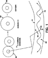
図1は、PET技術が機能する物理プロセスの例示である。
図2は、本発明が具体化されるPET装置の概略図である。
図3は、無機光発生クリスタルにおける円錐形の直接光を示す概略図である。
図4(a)及び4(b)は、それぞれ本発明の第1の実施例及び第2の実施例に従ってWLSF読み出しに結合された光発生クリスタルを示す。
図5(a)は、単一WLSFの端面図である。
図5(b)は、同じ単一WLSFの側面図である。図6(a)は、本発明の好ましい実施例に従うWLSFリボンに結合されたクリスタル配列を示す。
図6(b)は、図6(a)の実施例に従いWLSFに結合された一つのクリスタルの詳細図である。
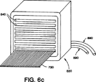
図6(c)は、本発明の実施例に従いWLSF読み出しに結合されたマルチアノードPS−PMTを示す。
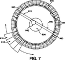
図7は、PET用途で使用されるような本発明の好ましい実施例を示している。
発明の説明
図1は、PET映像を形成するときのトレーサー運動モデル及び関連した物理学の一例を示している。まず、所望の生物学的働きを有する化学化合物には、放射性同位元素の表示がされており、かつ、これは被検者内に導入される。一例として、図1においては、一酸化炭素60の放射性同位元素が使用される。このような分子は、11C−カルボキシヘモグロビンを形成することによってヘモグロビンのためのトレーサーとして作用することができるであろう。この説明の目的のために、この被検者は、その一つを組織10で示す多数の材質から成る人間であると仮定している。しかしながら、本発明は、内部で生じる能動的生物学的プロセスを有するいかなるタイプの被検者も映像化するために使用することができるということが理解されるであろう。
放射性同位元素60が被検者内で処理されるとき、それは、陽電子20を放射することによって、連続的に崩壊する。図1の例において、11C−一酸化炭素は、11B−ボロン40及び酸素50を形成するために結合が解かれる。放出されると、陽電子は、被検者のすぐ周りを取り巻く組織10内の電子30と、直ちに結合する。陽電子20のそれぞれが、一つの電子30と結合して、両方の粒子が消滅する。この消滅の結果として、2つのガンマ線(それぞれ511keV)70及び80が発生する。これら2つのガンマ線は、ほとんど反対方向に同時に放出される。それらは、被検者の組織を通過し、かつ、本発明の主題である多数のセンサーによって外部で記録される。
図2は、診断されるべき被験者内に位置した放射性同位元素を映像化するために使用することができるPET装置の典型的実装を例示している。この実施例において、ガンマ線センサー110は、映像化される対象130を取り巻くようにリング構成内に形成される。放射性同位元素140は、対象130内に包含されている。この図は、比較的に少数のセンサー110を示しているけれども、かなり有効な解像度を達成するために、動作システムは、もっと多数を有しているであろう。さらに、この装置において、対応センサー150及び160は、それぞれ同時に、ガンマ線170及び180を検出するということが見られるであろう。
前述したように、PETにおける主要な限界は、空間解像度である。結局、解像度は、消滅プロセスの物理学によって制限される。これは、表示材質として選択される特別の放射性同位体に依存して、0.2〜2.6mmの広い範囲に渡る。さらに、解像度は、例えば、それぞれ50cm及び100cmの検出器分離で、1.4mm〜2.8mmに相当する180°+/-0.3のガンマ対開口角変動によって、悪く影響される。このように、PET解像度は、無制限のセンサー数及び/又は材質の費用にもかかわらず、理論的に略2又は3mmに制限されるということが理解できよう。
PET映像化のためのものである多くの構成は、2mm又は3mmよりもずっと小さく、或いは事実上、いくぶん小さい。これは、特に、多くの人間でない(即ち、実験動物)用途において当てはまることである。細かな空間解像度に対する要求は、センサーが、映像化される対象のサイズに匹敵するスケールで区分されるということである。それ故、検出器技術よりもむしろPETプロセスの物理学によって制限される装置は、ガンマ入射方向に直交する実効サイズ3mm或いはそれ以下のセンサーセルを有するべきである。
この新規なセンサーの好ましい実施例の動作における一連の事象は、次の通りである。
陽電子は、映像化される対象(患者)内の放射性同位体によって放出され、かつこれは、取り巻き組織内で消滅して、バックツウバックで511keVの消滅ガンマ線を発生し、或いは、映像化される対象内で放射性核種が低エネルギー(50−400keV)のガンマ線を発生するために崩壊する。
それから、各ガンマ線は、コンプトン散乱又は光吸収のいずれかを通して、無機光発生クリスタル内で相互作用する。この相互作用で発生した電子によるエネルギー堆積は、クリスタル内に光を生じる。クリスタル内に発生した光の波長は、クリスタルの固有の特性による。例えば、ヨウ化ナトリウム(NaI)のピーク放出は415nmであり、ヨウ化セシウム(CsI)のそれは310nmである。
クリスタル内で発生した光は次に、クリスタルの表面に伝搬する。もし、それが、入射して表面に当たると、それは内部で反射し、かつ別のクリスタル面上に現れる。もし、それが、この表面にほとんど垂直に通過するとき、それはクリスタルから出て、波長シフト光ファイバ(WLSF)に入る。他のクリスタル表面から出る光は、(ホトセンサーへの直接光結合のような)他の技術によって、或いは他のファイバによって、検知することができる。
WLSFに入る光は吸収され、異なる波長の光を放出する。即ち、吸収され、或いは放出される光波長の範囲は、使用されるWLSFのタイプに依存する。典型的WLSFは青の光を吸収して、緑の光を放出するが、他の光学動作のファイバがまた使用可能である。例えば、UVを吸収し、青を放出するファイバがまた可能である。WLSFの配列(リボン)が、クリスタルから出る光の位置を符号化し、かつそれによって、エネルギー堆積の位置を符号化する。WLSFリボンはそれから、波長シフト光の一部をホトセンサーに伝達し、かつこのホトセンサーは、典型的には、クリスタルから1メータ以下の距離離れている。
ホトセンサーにおいて、WLSF光の量によって符号化されるようなエネルギー堆積値、及びリボン内の波長シフト光の位置によって符号化されるようなエネルギー堆積の位置が検知される。もし位置検知ホトセンサーが使用されるならば、その時、ファイバリボンからの光がホトセンサーに入る位置は、電気パルスに符号化される。これらのパルスの時間及び大きさがまた、ガンマ到達時間、及びクリスタル内に堆積したエネルギー量を示している。或いは、個々の光センサーは、単独ファイバ又はファイバ組からの光を検知するために使用することができる。即ち、個々の光センサー上の分離リボンからのファイバを多重化することによって、必要とするホトセンサーの合計数を最小化することができる。

センサー構成はさらに、光発生クリスタルに結合され、かつ読み出すために、波長シフト光ファイバ(WLSF)を使用する。WLSFの選択は、クリスタルの光放出をファイバの光吸収に適合させるように決定される。詳細な最適化は、特別の装置、例えば、移動可能のガンマ線カメラ、SPECT検出器、或いはPET検出器の使用によって決定する性能要求に合致するようになされなければならない。しかしながら、一般に、新規な検出器構成は、クリスタル及びWLSFの特別の選択とは無関係に機能する。
前述したように、この技術は、どの組の非常に小さなクリスタルがガンマ線相互作用を包含したかを識別し、或いはより大きなクリスタル内で、ガンマ線相互作用がどこで生じたかを位置決めするために使用することができる。本発明の好ましい実施例において、(コンプトン散乱又は光捕捉のいずれかを通して低エネルギーガンマ線又は入射消滅ガンマ線によって発生する)イオン化電子によって光発生クリスタル内で発生するシンチレーション光は、クリスタル内で等方性に放出される。表面法線に関して(クリスタルの屈折率によって決定される)臨界角よりも大きな角度で磨いたクリスタル面に当たる部分光は、クリスタル内部で完全に反射する。クリスタルの表面上の残りの非反射光の分布は、図3に示されている。この光230は、後述のように、図2に示すガンマ線センサー110のコンポーネントであるクリスタル210内のエネルギー堆積220の位置の情報を提供する。クリスタル210を出る直接光230は、クリスタル210内で生じるエネルギー堆積220のタイミング及びその量に関する有用な情報を提供する。
図4(a)及び4(b)は、クリスタルに関するWLSFの位置決めの別の実施例を示している。完全に内部で反射した光は、他のクリスタル面から反射するかもしれないし、そして結局、別のクリスタル面から出るかもしれない。クリスタル210の1以上の表面に、ファイバーりぼん読み出しを備えることができる。即ち、(図4(a)に示されるように)与えられたクリスタルの両側で直角に2つのリボン310及び320を配置することによって、エネルギー堆積位置220は、2次元で決定することができる。或いは、部分的に半透明なWLSFが(図4(b)に示されるように)使用することができ、そのため、両方の直交ファイバリボン410及び420がクリスタル210の一つの側に位置させることができる。WLSFを下方に伝達される一部の光を検知することに加えて、(後述のように)光学ファイバ内で捕捉されない光は、WLSFリボン310及び320又は410及び420に結合された1以上のホトセンサー330によって検知することができる。WLSFがクリスタル210に接触する位置でWLSFリボンに、或いはクリスタル210に直接結合された一つのホトセンサー330、及びWLSF光パイプの端の第二のホトセンサー(図示せず)を使用することによって、エネルギー堆積局部測定(パイプ測定)と、(直接結合する)エネルギー堆積の大きさの測定の機能を分離することが可能である。ガンマカメラ又はSPECTのための好ましい実施例において、直交するファイバリボンは位置感知ホト増倍器によって読み出されるが、一方のこのようなファイバリボンはクリスタルと第二のホト増倍器の間にサンドイッチにされる。
図5(a)及び5(b)を参照すると、ここで使用される個々のWLSFの、それぞれ端面図と側面図が示されている。WLSFは、光導波ガイドをドーパント剤と組み合わせる。ドーパント剤は各吸収ホトンが相当する放出ホトンを出すようにして、それが短波長光を吸収し、より長い波長の光を再放出するように選択される。再放出光の一部は、好ましい実施例で使用される位置感知ホト増倍器管のような光センサーの内部反射開口内に捕捉される。
図5(a)及び5(b)に示されるように、入射ホトン520は、図4aに示すWLSFリボン310、312の1つの断面図を示したファイバ510のファイバクラディング530を通過した後吸収される。いったん吸収されると、光の一部は、全て内部で反射され、かつ、再放出ホトン570は、ファイバコア590内をファイバ510を通して伝達される。
プラスチックWLSFは、世界的規模のいくつかの製造元によって製造されており、かつ、1本のファイバ厚さで、多数ファイバ幅のリボンにしばしば組み立てられている。このような製造元の一つは、オハイオ州ニューベリーのビクロン、コーポレーション(Bicron Corporation)である。ここで使用するために適したWLSFは、ビクロンによって製造された(リボン形態の)BCF−92ファイバであるが、他のものを本発明から離れることなく代用することができる。1.0mmの厚さのファイバ上に入射する光の吸収及び再放出の効率は、90%に近づき、かつ、ファイバ軸に沿って光学的に捕捉される光の減衰長さは2mmである。クリスタルを出る光のほんの8%が、読み出しで使用するためにファイバ端の方に光学的に伝達されるということが理解されよう。ビクロンBCF−92ファイバに対して、ピーク吸収波長は、405nmであり、かつ放出スペクトラムのピークは、494nmである。コアの屈折率は、1.60である一方、クラディングのそれは、1.49である(4%以上の捕捉率を生じる)。発生光はさらに、第一のものの外側に第二の低指数のクラディングを有するダブルクラッドファイバを利用することによって増加させることができる。これは典型的には、等価なシングルクラッドファイバよりも略50%高い捕捉率となる。
図6(a)、6(b)及び6(c)は、ガンマ線カメラのための検出器設計の好ましい実施例を集合的に例示している。この実施例は、光学的に分離した(クリスタルコンタクト表面がそれらの間に鏡のような、或いは拡散する反射器を有するということを意味している)12cm平方で、1cm深さの無機光発生クリスタル710の3×3配列から構成される。このように、好ましい実施例におけるクリスタル配列は、1cm深さの、36cm×36cmである。このクリスタル配列は、2つの直交波長シフトファイバリボン730及び740の間に置かれる。この様にして、(x及びy方向の両方の)位置に関する情報、エネルギー堆積の時間及び値は、クリスタル710から伝達され、波長シフトされ、かつWLSF730及び740内に捕獲される。それから、光は、WLSF730及び740を通して、ホトセンサー830に伝搬される。光発生は、同じホトセンサー830によって、WLSF730及び740の両方の端で読み出すことによって、或いは、WLSF730及び740の一端をミラーすることによって、増加させることができる。図6(a)は、ミラー化ファイバ端を有する一実施例を例示している。
図6(b)は、図6(a)の円によって示された12cm平方×1cm深さのクリスタルの詳細図である。本発明の好ましい実施例で使用されるWLSFリボンは、12cm×12cm×1cmクリスタル710の一表面上の一対の1mm×60mmリボン730、及び反対のクリスタル面上の別の対の同一のWLSFリボン740であり、その第二の対は、第一に関して90°の方向にされている。或いは、クリスタル面をカバーするに十分な幅の単一WLSFリボン740を使用することができる。クリスタル710におけるエネルギー堆積の直接結合読み出しを得るために、ホト増倍器760が、図6(b)に示されるように、1組の直交WLSFリボンの上に直接置かれる。図6(a)及び6(b)に図示されていないけれども、追加のWLSFリボンが、前述の全て内部で反射した光を集めるためにクリスタル710の残りの小さなエリア面上に置くことができる。WLSFの比較的に短い部分が図示されているけれども、使用される実際のリボンは、100cmの長さにすることができるということが理解されよう。
位置感知ホト増倍器(PS−PMT)830が、図6(c)に示されている。本発明の好ましい実施例において、X−Y PS−PMT読み出しが使用される。これは、光発生器が直接PS−PMTに結合されている従来技術の装置よりもチャンネル計数が減少し、位置解像度が細かくなり、そして効率が高くなる。或いは、ピキシレートタイプのPS−PMTを、高事象率用途に使用することができるであろう。X−Y P S−PMTを使う一実施例の特別の実装において、ハママツ4135−01PS−PMTを使用することができる。この装置は、日本の浜松にあるハママツ・コーポレーションから手に入れることができる。PS−PMT装置において、1.0mm×60mmWLSFの3以下のリボンが、このPS−PMT830上の8入力領域840のそれぞれに結合することができる。PS−PMTの動作はこの技術分野において一般に公知であるけれども、以下のように簡単な説明をする。
WLSF730から伝送される出力光がホトカソードに達するとき、このホトカソードは、ホトエレクトロンを放出させられる。このホトエレクトロンは、空間的広がりを維持しながら、それらが光増倍を受けるとき一群のダイノードに加えられる。次に、それらは、複数の出力ターミナルを有する抵抗分割型アノードに加えられる。入射位置及びホトエレクトロンの量は、出力ターミナルを通してデータとして出力される。エマシエート(Emaciate)の米国特許No.4,929,835は、このプロセスの詳細を述べている。
各入力領域と関連した2つのパルスの電荷の比を測定することによって、(60mm幅に沿って)リボン730を横切る座標は、2mm以内に再構成することができる。PS−PMT830内の8入力領域840のそれぞれが、3つのリボンからの情報を符号化することができる。クリスタルの一つの3×3配列は、それぞれ1mmの厚さ及び60mmの横断長である全部で12のWLSFリボンを包含している。ホト増倍器830はさらに、データを追加の処理要素に提供する2つの信号ライン890(変化分割読み出し)を包含している。
本発明の好ましい実施例は、(X−Y又はピキシレート)PS−PMTの関係で前述したけれども、PS−PMTのために他のホトセンサーを代用することは可能であるということに注目されるべきである。特に、ホトダイオード、アバランシェホトダイオード、或いはハイブリッドホトダイオード(ホトカソード/ホトダイオード組合せ)が、本発明の目的を達成するための全ての可能な構成である。WLSF内の光の集中は、従来技術の方法よりも小さなホトカソード読み出しエリアを有する装置を可能にし、それによって、より細かい空間解像度を有するより小さなホトセンサーを使用する能力を提供する。
細かな横断及び軸方向空間解像度を提供することに加えて、無機光発生クリスタルWLSF/PS−PMT検出器は、クリスタル内の相互作用の深さを容易に測定することができる。高解像度検出器用途に対して、相互作用の深さの曖昧さは、リングの軸からある距離を置いたところに陽電子ソース位置の映像作り物(放射状に長くなること)を形成する。相互作用深さ軸に沿って60mmの幅を持つ読み出しファイバリボンを位置決めすることにより、我々は、一つのクリスタルにおいて(或いはファイバリボンによって並列に読み出される数個のクリスタルのいずれかにおいて)相互作用の深さを測定する前述の技術を使用することができる。相互作用解像度の5mmFWHM(Full Width Half Max.)深さがPET用途において放射状に長くなることを完全に除去するために十分である一方、相互作用解像度の3mmの深さが、WLSFリボン読み出しによって容易に得ることができる。
PET用途のための無機クリスタルWLSF/PS−PMTの好ましい実施例が、図7に示されている。この実施例において、直接読み出しホトセンサー910が、映像化される対象930を取り巻くようにリング構成内に形成されている。放射性同位元素940は、対象930内に包含されている。この図は、比較的に少数の直接読み出しホトセンサー910(図4aに示すホトセンサー330に対応する)を示しているけれども、動作システムは、かなり有効な解像度を達成するために、もっと多数を有するであろう。この装置において、対応センサー950及び960(図2に示す対応センサー150及び160と同じ特徴を持つ)は、それぞれ同時にガンマ線970及び980を検出するということが見られよう。
エネルギー及びタイミング測定(直接読み出し)の機能及び局所化(ファイバ読み出し)の機能は分離される。数個のPETリング(リングの中心軸に沿って二重化される分離ユニット)が、単一組の軸方向ファイバ945(図2のWLSFリボン310の断面を示す)によって読み出すことができる。円周方向ファイバ935は、各PETリングそれぞれのために相互作用深さ測定を実行する。対応センサー950及び960は、ファイバ935上の光を検出する。超高精度PETに対して、単一軸方向ファイバを使用して、1mmの幅以下にすることができる各光学的に分離されたクリスタルを読み出すことができる。このようなPET検出器は、システムコストを低くして、現在の技術よりも優れた解像度を有している。
無機光発生クリスタルWLSF/PS−PMT検出器構成の応用は、医療映像のみに制限されない。天体物理学、実験核物理学、商用原子炉、及び放射性同位体材料のバイオメディカル映像への応用が可能である。天体物理学及び核実験例において、大エリアガンマカメラを、無機クリスタル及び波長シフトファイバを使って、低コストで実装することができるであろう。原子炉及び放射性材料を包含する他の設備のために、この技術は、放射ソースを位置決めするために使用される映像装置に組み入れることができ、そして、コストを低くしながらシステム感度を改善する。放射性同位元素は、バイオケミカル研究を分類するバイオメディカル研究において共通に使用される。この目的のために使用される映像放射検出器は、提案された簡単化読み出し技術を使用することによって、感度が改善されかつコストが減少させることができる。すべてのこのような応用において、ホトセンサー及び関連したエレクトロニクスの数(及びエリア)を減少させた結果、コストが節約され、或いは検出器サイズ及び感度が増加した。さらに、無機クリスタル光発生器と組み合わせて波長シフトファイバを使用することは、ガンマ放射だけの映像化に制限されず、アルファ及びベータ粒子、中性子、陽子、及び核崩壊断片のような他の形態のイオン化放射が全て、システムコストを減少させ、かつ感度を増加させて、映像化することができる。
本発明は特に、特別の実施例を参照して説明したけれども、本発明の精神、範囲、又は教示から離れることなく、種々の他の変化が細部においてなすことができるということが当業者によって理解されるであろう。Field of Invention
The present invention generally relates to an apparatus and technique for the detection and imaging of ionizing radiation, and more particularly to a gamma ray detector using a light generating crystal coupled to a wavelength shifted optical fiber.
Background of the Invention
Current nuclear medicine provides a variety of techniques for non-invasive diagnosis of internal body composition and biochemical processes that occur within a patient. Computerized axial tomography (CAT), nuclear magnetic resonance imaging (MRI) scanning, and conventional X-ray techniques are examples of such structural imaging systems. These techniques, which identify and identify only body structures, have the drawback that by the time an abnormality appears and is detected, the pathological conditions that cause such an abnormality often progress considerably.
In contrast, positron emission tomography (PET) systems are used to image other parts of the body along with a functioning metabolic system in the brain. By imaging functionality rather than structure, these systems uniquely complement and complete X-ray, CAT, and MRI systems. PET is achieved through the detection of co-occurring paired gamma rays. These gamma rays are generated when positrons emitted from a source (typically placed in the patient's body) are annihilated by electrons in the tissue surrounding the source location. When gamma rays are generated by this annihilation, due to the physical properties of these subatomic particles and other known properties, the two gamma rays will be emitted with a single energy. This known characteristic is that, for example, gamma rays are emitted so as to travel in almost opposite directions.
The PET imaging process involves a number of steps. Proton-rich radioisotopes are initially placed in the patient's body, for example, by injection or ingestion. In most cases, these isotopes are concentrated at or near the area where diagnosis is desired. Once incorporated into the body, this isotope continues to emit positrons as part of the naturally occurring decay process. A positron is an anti-electron that travels a short distance and then combines and annihilates with electrons from the surrounding tissue. When annihilated, both the electrons and the positrons are converted into electromagnetic radiation. In order to conserve energy and linear momentum, electromagnetic radiation is a form of two gamma rays that are equal in energy and emit at approximately 180 ° to each other. As the positron emitter moves through the body, it is this annihilation radiation that is detected externally in the PET device to measure both its quantity and position.
As the radioisotope moves through and is processed by the patient's body, its concentration can be measured and displayed as a cross-sectional grayscale (black and white tone display) image. In this image, the intensity of each pixel is proportional to the concentration of the radioisotope at that location in the body. This type of so-called “kinematic” technology has been one of the most powerful methods for diagnosing and analyzing dynamic processes such as blood flow, substrate transport and biochemical reactions in the human body. However, it will continue to be in the same way.
Existing PET systems can simultaneously record and process multiple tomographic images of the human brain or torso. Furthermore, the sensor can be positioned either in a planar ring configuration that can form a 2D image, or in a volume layout that achieves a 3D image. This latter layout is called Positron Volume Imaging (PVI), but some people use the term “PET” for it when referring to this PVI. PVI can be set to first process the data as PET data and later combine the planar images to form a volumetric image. Alternatively, PVI can be achieved by allowing inter-plane coincidence at the sensor location and thus handling these coincidence detections. The resolution that can be achieved with any of these systems has recently been narrowed to less than 1 centimeter and the activity distribution within the subject can be assessed within a few percent.
In a typical PET installation, the ring of gamma sensors is positioned to surround the patient at the local location of the radioisotope source. This detection process takes advantage of both the fact that gamma emission occurs at 180 ° to each other and the fact that gamma rays occur simultaneously. Simultaneous detection of gamma rays by sensors on both sides of the patient defines an annihilation position on or near the line connecting the centers of the two sensors. If a single detection is performed, annihilation typically has occurred outside the volume or plane between the two detectors. In this case, no events are recorded because the source is located outside the diagnostic area.
Available PET systems typically include a radiation sensor and its associated circuitry, a high-speed computer with the necessary imaging software, and a mass memory for storing and processing the sensor and other input data. Includes the data acquisition subsystem described above. A display system for viewing the video immediately is also typically provided. Finally, it generally includes means for interaction processing and user system controller.
As early as 1986, dozens of cyclotron PET regional centers were operating under global development, and the number continues to grow. Cyclotron PET centers are typically chemical laboratories for the synthesis of accelerators (usually small medical cyclotrons), positron emission tomography (PET), and short-lived biological radiation tracers to generate radioisotopes Consists of. In the United States, many such centers can be found in university-established medical research centers. Modern high-resolution PET detectors cost over $ 1 million, including about $ 100,000 for crystals and $ 250,000 for photosensors (typically photomultipliers) is there.
Since PET was first realized in the 1970s, it has continued to improve. Unfortunately, modern high-resolution PET systems are operating at or near the inherent limits imposed by the physics of this technology. There are statistical limitations due to limited patient exposure to positron emitting radioisotopes, and the source position is unclear due to the positron range and residual momentum upon extinction, which limits the resolution and accuracy of the image. There is. Furthermore, systems that operate near this inherent limit are rather complex and very expensive. This is due in part to the need for a large number of sensor elements to achieve the desired resolution.
Current PET detection techniques are also subject to various inaccuracies resulting from the reduction in crystal width when higher resolution is required. These inaccuracies are commonly referred to as “imaging artifacts”. One such artifact is radial blurring, which results from crystal penetration from a source away from the axis of the system. In other words, if the coincidence line is located some distance from the diameter of the detector ring, the gamma rays may pass through one or several crystals before being absorbed by the detection crystal. it can. This in turn extends the simultaneous aperture function towards the edge of the field of view. This problem is further complicated when the decay length of the crystal material increases. In order to achieve equivalent efficiency when using a crystal material with a longer attenuation length (where such a crystal would otherwise have the desired properties such as high brightness, high speed, low cost The crystal depth must be increased correspondingly. However, once the crystal is deepened, radial blur increases. Even with the shortest decay length crystals currently in use, radial blurring limits system resolution for objects several centimeters from the center axis of the detector. Various proposals have been made to solve this problem, and the main solution is to use an interaction depth measurement for photons interacting in the detector. Modern imaging systems determine the special location of gamma-ray interactions by using dense light-generating crystals such as bismuth garminate, by using very narrow crystals, and in larger crystals Attempts have been made to minimize image artifacts by using special sensors. Various methods have been proposed to measure the depth of interaction in very high resolution PET detectors, but all of these measurements are associated with many additional photosensors (such as photodiodes). Either electronics or a complex coding arrangement was required.
Another type of imaging device used in clinical nuclear medicine applications is the single photon emission computed tomography (SPECT) system. The detectors used for SPECT have many common attributes with PET detectors, although the position resolution requirements are typically much smaller. In the SPECT imaging process, a radioactive tracer is first placed in the patient's body by injection or ingestion. This radioisotope decays by emitting continuously low energy gamma rays (photons) as it travels through the patient's body. It is this photon radiation that is detected from the outside by the SPECT apparatus. The photon radiant energy detected by the SPECT apparatus is typically in the range of 55-400 keV, which is lower than the annihilation gamma ray energy (511 keV) of the PET system. The widely used radionuclide is the technitium isomer, 99 mTc, and it has a half-life of 6 hours (the time required for half of the radionuclides originally present to decay). 99 In the case of mTc, this radionuclide decays by continuously emitting gamma rays, and the energy of the gamma rays is 140 keV. Several commonly used isotopes are listed here along with decay photon energy and corresponding body imaging functions.
・ 201 Tl, 80 keV; used for heart and torso imaging.
・ 176 Ta, 55-65 keV; used to image the heart.
・ 133 Xe, 80 keV; used for lung and respiratory system studies.
Ordinary SPECT devices require the use of a collimator usually constructed from a thick lead sheet with thousands of small holes placed directly in front of the gamma camera (crystal detector). In general, the collimator holes are perpendicular to the crystal so as to prevent the passage of photons incident obliquely on the crystal detector, thereby selecting the direction of the incident photons. By rotating the gamma camera and / or collimator around the patient, a series of two-dimensional projections can be formed from different directions. By applying various reconstruction techniques, the internal distribution of the radioactive tracer can be modified simultaneously for a parallel two-dimensional cross section. This SPECT technique can be used for 3D imaging of radioactive tracer distributions located in the lung, heart and brain. A typical gamma camera for use with SPECT typically uses 36-90 photomultipliers, such as photosensors, with associated readout electronics. In part due to this internal complexity, commercial SPECT systems cost approximately $ 200,000 to $ 500,000.
Summary of invention
Therefore, it is an object of the present invention to provide a simplified gamma ray detector configuration.
Another object of the present invention is to provide a detector arrangement with high video resolution.
Yet another object of the present invention is to reduce the number of sensor elements and reduce the cost of each sensor element.
Yet another object of the present invention is to increase the resolution of the video system while simultaneously reducing the number of sensor elements required.
Yet another object of the present invention is to measure interaction depth to alleviate the problem of image artifacts.
The foregoing objects are achieved by the novel detector element configuration described below and its method of use. In a preferred embodiment, one or more inorganic light generating crystals are coupled to a position sensitive photomultiplier (PS-PMT) through a wavelength shifted optical fiber (WLSF). The superior detector configuration according to the present invention is designed for an array of applications in high spatial resolution gamma ray detection, with particular application to SPECT, PET and PVI imaging systems. This design lowers overall cost and provides better position resolution than prior art devices. By using wavelength-shifting fiber (WLSF), the sensor configuration of the present invention significantly reduces the number of photomultipliers and electronics channels while allowing three-dimensional reconstruction of the energy deposition position. It can operate with potentially improved resolution.
[Brief description of the drawings]
FIG. 1 is an illustration of a physical process in which PET technology functions.
FIG. 2 is a schematic diagram of a PET apparatus in which the present invention is embodied.
FIG. 3 is a schematic diagram showing conical direct light in an inorganic light generating crystal.
FIGS. 4 (a) and 4 (b) show a photogenerating crystal coupled to a WLSF readout in accordance with the first and second embodiments of the present invention, respectively.
FIG. 5A is an end view of a single WLSF.
FIG. 5 (b) is a side view of the same single WLSF. FIG. 6 (a) shows a crystal array bonded to a WLSF ribbon according to a preferred embodiment of the present invention.
FIG. 6 (b) is a detailed view of one crystal coupled to WLSF according to the embodiment of FIG. 6 (a).
FIG. 6 (c) shows a multi-anode PS-PMT coupled to WLSF readout according to an embodiment of the present invention.
FIG. 7 shows a preferred embodiment of the present invention as used in PET applications.
Description of the invention
FIG. 1 shows an example of a tracer motion model and associated physics when forming a PET image. First, a chemical compound having a desired biological function is labeled with a radioisotope, and this is introduced into a subject. As an example, in FIG. 1, a radioisotope of
As the
FIG. 2 illustrates an exemplary implementation of a PET device that can be used to image radioisotopes located within a subject to be diagnosed. In this embodiment, the
As previously mentioned, the major limitation in PET is spatial resolution. Ultimately, resolution is limited by the physics of the annihilation process. This ranges over a wide range of 0.2 to 2.6 mm, depending on the specific radioisotope selected as the display material. Furthermore, the resolution is adversely affected by gamma versus aperture angle variation of 180 ° +/− 0.3, corresponding to 1.4 mm to 2.8 mm, for example, with detector separations of 50 cm and 100 cm, respectively. Thus, it can be seen that PET resolution is theoretically limited to approximately 2 or 3 mm, despite the unlimited number of sensors and / or material costs.
Many configurations that are for PET imaging are much smaller than 2 mm or 3 mm, or in fact somewhat smaller. This is especially true in many non-human (ie laboratory animal) applications. The requirement for fine spatial resolution is that the sensor is segmented on a scale comparable to the size of the object being imaged. Therefore, a device that is limited by the physics of the PET process rather than detector technology should have a sensor cell with an effective size of 3 mm or less orthogonal to the gamma incidence direction.
The sequence of events in the operation of the preferred embodiment of this novel sensor is as follows.
Positrons are emitted by radioisotopes in the subject (patient) being imaged, and they disappear in the surrounding tissue, generating 511 keV annihilation gamma rays back-to-back, or imaged. Radionuclides decay within the subject to generate low energy (50-400 keV) gamma rays.
Each gamma ray then interacts within the inorganic light-generating crystal through either Compton scattering or light absorption. Energy deposition by electrons generated by this interaction generates light in the crystal. The wavelength of the light generated in the crystal depends on the unique characteristics of the crystal. For example, the peak emission of sodium iodide (NaI) is 415 nm and that of cesium iodide (CsI) is 310 nm.
The light generated in the crystal then propagates to the surface of the crystal. If it is incident and hits the surface, it reflects internally and appears on another crystal plane. If it passes almost perpendicular to this surface, it exits the crystal and enters a wavelength shifted optical fiber (WLSF). Light emerging from other crystal surfaces can be detected by other techniques (such as direct light coupling to a photosensor) or by other fibers.
Light entering the WLSF is absorbed and emits light of different wavelengths. That is, the range of light wavelengths that are absorbed or emitted depends on the type of WLSF used. A typical WLSF absorbs blue light and emits green light, but other optically operating fibers can also be used. For example, fibers that absorb UV and emit blue are also possible. An array of WLSF (ribbons) encodes the position of light exiting the crystal and thereby encodes the position of energy deposition. The WLSF ribbon then transmits a portion of the wavelength shifted light to the photosensor, which is typically a distance of 1 meter or less from the crystal.
In the photosensor, the energy deposition value as encoded by the amount of WLSF light and the position of energy deposition as encoded by the position of the wavelength shifted light in the ribbon are detected. If a position sensitive photosensor is used, then the position where the light from the fiber ribbon enters the photosensor is encoded into an electrical pulse. The time and magnitude of these pulses also indicate the gamma arrival time and the amount of energy deposited in the crystal. Alternatively, individual light sensors can be used to detect light from a single fiber or fiber set. That is, by multiplexing the fibers from the separation ribbons on the individual photosensors, the total number of photosensors required can be minimized.
The sensor configuration further uses a wavelength shifted optical fiber (WLSF) to couple to and read from the light generating crystal. The choice of WLSF is determined to match the light emission of the crystal to the optical absorption of the fiber. Detailed optimization must be made to meet the performance requirements determined by the use of special equipment such as movable gamma cameras, SPECT detectors, or PET detectors. In general, however, the new detector configuration works independently of the particular choice of crystal and WLSF.
As mentioned earlier, this technique can be used to identify which set of very small crystals involved gamma ray interactions, or to locate where gamma ray interactions occurred within larger crystals. Can do. In a preferred embodiment of the present invention, the scintillation light generated in the photogenerating crystal by ionizing electrons (generated by either low energy gamma rays or incident annihilation gamma rays through either Compton scattering or light capture) isotropic in the crystal. Released. Partial light hitting the crystal surface polished at an angle greater than the critical angle (determined by the refractive index of the crystal) with respect to the surface normal is completely reflected inside the crystal. The distribution of the remaining non-reflected light on the surface of the crystal is shown in FIG. This light 230 provides information on the position of the
4 (a) and 4 (b) show another example of WLSF positioning with respect to the crystal. Light that is totally internally reflected may be reflected from other crystal surfaces and may eventually exit from another crystal surface. One or more surfaces of the
Referring to FIGS. 5 (a) and 5 (b), there are shown an end view and a side view, respectively, of the individual WLSF used here. WLSF combines an optical waveguide guide with a dopant agent. The dopant agent is selected such that each absorbing photon emits a corresponding emitted photon that absorbs short wavelength light and re-emits longer wavelength light. A portion of the re-emitted light is captured in the internal reflective aperture of a photosensor such as a position sensitive photomultiplier tube used in the preferred embodiment.
As shown in FIGS. 5 (a) and 5 (b), the
Plastic WLSF is manufactured by several worldwide manufacturers and is often assembled into multiple fiber width ribbons with a single fiber thickness. One such manufacturer is Bicron Corporation, Newbury, Ohio. A suitable WLSF for use herein is BCF-92 fiber (in ribbon form) manufactured by Vicron, but others can be substituted without departing from the invention. The efficiency of absorption and re-emission of light incident on a 1.0 mm thick fiber approaches 90%, and the attenuation length of light optically captured along the fiber axis is 2 mm. It will be appreciated that only 8% of the light exiting the crystal is optically transmitted towards the fiber end for use in readout. For a Bicron BCF-92 fiber, the peak absorption wavelength is 405 nm and the peak of the emission spectrum is 494 nm. The refractive index of the core is 1.60, while that of the cladding is 1.49 (resulting in a capture rate of 4% or more). The generated light can be further increased by utilizing a double clad fiber having a second low index cladding outside the first one. This typically results in a capture rate that is approximately 50% higher than an equivalent single-clad fiber.
6 (a), 6 (b) and 6 (c) collectively illustrate a preferred embodiment of a detector design for a gamma camera. This embodiment is a 12 cm square, 1 cm deep inorganic light generating optically separated (meaning that the crystal contact surface has a mirror-like or diffuse reflector between them) Consists of a 3 × 3 array of
FIG. 6B is a detailed view of a 12 cm square × 1 cm deep crystal indicated by the circle in FIG. The WLSF ribbons used in the preferred embodiment of the present invention are a pair of 1 mm × 60
A position sensitive photomultiplier (PS-PMT) 830 is shown in FIG. In the preferred embodiment of the present invention, an XY PS-PMT readout is used. This results in a reduced channel count, finer position resolution and higher efficiency than prior art devices where the light generator is directly coupled to the PS-PMT. Alternatively, a poxylate type PS-PMT could be used for high event rate applications. In a particular implementation of one embodiment using XYPS-PMT, Hamamatsu 4135-01PS-PMT can be used. This device can be obtained from Hamamatsu Corporation in Hamamatsu, Japan. In the PS-PMT device, 3 or less ribbons of 1.0 mm × 60 mm WLSF can be coupled to each of the 8
When the output light transmitted from the
By measuring the ratio of the charges of the two pulses associated with each input region, the coordinates across the ribbon 730 (along the 60 mm width) can be reconstructed within 2 mm. Each of the eight
It should be noted that although the preferred embodiment of the present invention has been described above in the context of (XY or Pixylate) PS-PMT, other photosensors can be substituted for PS-PMT. It is. In particular, photodiodes, avalanche photodiodes or hybrid photodiodes (photocathode / photodiode combinations) are all possible configurations for achieving the objects of the present invention. The concentration of light in the WLSF allows devices with a smaller photocathode readout area than prior art methods, thereby providing the ability to use smaller photosensors with finer spatial resolution.
In addition to providing fine transverse and axial spatial resolution, the inorganic light generating crystal WLSF / PS-PMT detector can easily measure the depth of interaction within the crystal. For high-resolution detector applications, the ambiguity in the depth of interaction forms an image artifact (radially long) of the positron source position at a distance from the ring axis. By positioning a readout fiber ribbon with a width of 60 mm along the interaction depth axis, we can interact with one crystal (or any of several crystals read in parallel by the fiber ribbon). The techniques described above for measuring depth can be used. An interaction resolution of 5 mm FWHM (Full Width Half Max.) Depth is sufficient to completely eliminate radial lengthening in PET applications, while an interaction resolution of 3 mm depth is facilitated by WLSF ribbon readout. Can get to.
A preferred embodiment of an inorganic crystal WLSF / PS-PMT for PET applications is shown in FIG. In this embodiment, a
The functions of energy and timing measurement (direct readout) and localization (fiber readout) are separated. Several PET rings (separation units that are duplexed along the central axis of the ring) can be read out by a single set of axial fibers 945 (showing a cross section of the
The application of the inorganic light generating crystal WLSF / PS-PMT detector configuration is not limited to medical images only. Applications to astrophysics, experimental nuclear physics, commercial nuclear reactors, and biomedical imaging of radioisotope materials are possible. In astrophysics and nuclear experiments, large area gamma cameras could be implemented at low cost using inorganic crystals and wavelength shifting fibers. For other equipment, including nuclear reactors and radioactive materials, this technology can be incorporated into the imaging device used to position the radiation source and improve system sensitivity while reducing costs. Radioisotopes are commonly used in biomedical research to classify biochemical research. Imaging radiation detectors used for this purpose can be improved in sensitivity and reduced in cost by using the proposed simplified readout technique. In all such applications, reducing the number (and area) of photosensors and associated electronics has resulted in cost savings or increased detector size and sensitivity. Furthermore, the use of wavelength-shifting fibers in combination with inorganic crystal light generators is not limited to imaging of gamma radiation alone, but other forms of alpha and beta particles, neutrons, protons, and nuclear decay fragments. All of the ionizing radiation can be imaged with reduced system cost and increased sensitivity.
Although the invention has been particularly described with reference to specific embodiments, those skilled in the art will recognize that various other changes can be made in the details without departing from the spirit, scope, or teaching of the invention. Will be done.
Claims (27)
それぞれが前記波長シフトファイバの少なくとも1つに直接結合された1つまたは1つ以上の無機光発生器(210)と、
前記1つまたは1つ以上の前記光発生器内のエネルギー堆積の時間及び位置を決定するため前記波長シフトファイバに結合されたホトセンサー手段(330)と、
から成る放射検出器。A plurality of wavelength shifting fibers (310, 320);
One or more inorganic light generators (210), each directly coupled to at least one of the wavelength shifting fibers;
Photosensor means (330) coupled to the wavelength shifting fiber to determine the time and position of energy deposition in the one or more light generators;
A radiation detector comprising:
前記生命組織体を取り巻き配置された光発生手段と、
前記光発生手段から離れた位置に配置されたホト検出器手段(330)と、
前記光発生器手段からの光を前記ホト検出器手段に伝達するための少なくとも1つの波長シフトファイバ(310)と、
前記生命組織体内の種々の位置で前記放射性合成物の濃度を表す映像を再構成するための手段と、
からなる前記スキャナー。In a positron emission tomography scanner for detecting and measuring biochemical and physiological changes in a living tissue associated with administering a radioactive compound to the living tissue,
A light generating means disposed around the living tissue;
Photo detector means (330) disposed at a position remote from the light generating means;
At least one wavelength shifting fiber (310) for transmitting light from the light generator means to the photo detector means;
Means for reconstructing images representing the concentration of the radioactive compound at various locations within the living tissue;
The scanner comprising:
前記無機クリスタル光発生器から離れた位置に配置されたホト検出器手段(330)と、
少なくとも1つの波長シフトファイバであって、それぞれの波長シフトファイバが、前記無機クリスタル光発生器からの光を吸収し、再放出し前記ホト検出器手段に伝達するようにして成る波長シフトファイバと、
映像化される前記対象内の前記ガンマ線の濃度を表す映像を再構成するための手段と、
から成るガンマ線映像化応用のためのシンチレーションカメラ。An inorganic crystal light generator (210) disposed at a position away from the object to be imaged;
Photo detector means (330) disposed at a position remote from the inorganic crystal light generator;
At least one wavelength shifting fiber, wherein each wavelength shifting fiber absorbs light from the inorganic crystal light generator, re-emits it and transmits it to the photo detector means;
Means for reconstructing an image representative of the concentration of the gamma rays in the object to be imaged;
A scintillation camera for gamma ray imaging applications.
前記放射性ソースを映像化されるべき被検者内に導入し、
前記被検者外部の位置から、前記ガンマ線対の各ガンマ線を、光発生クリスタル(210)内の前記ガンマ線の相互作用を通して検知し、
前記光発生クリスタル内の前記相互作用の結果として発生した光エネルギーを波長シフト光学ファイバ(310)を通して伝搬し、
前記波長シフト光学ファイバの位置の結果として、光発生クリスタル内の前記ガンマ線の前記相互作用の位置を決定し、そして、
前記生命組織体内の種々の位置で前記放射性ソースの濃度を表す映像を再構成する、各ステップから成る前記方法。In a method for reconstructing the position of a radioactive source located within a living tissue through simultaneous detection of gamma ray pairs,
Introducing the radioactive source into the subject to be imaged;
Detecting each gamma ray of the gamma ray pair from a position outside the subject through the interaction of the gamma rays in the light generating crystal (210),
Propagating light energy generated as a result of the interaction in the light-generating crystal through a wavelength-shifting optical fiber (310);
Determining the position of the interaction of the gamma rays in a light-generating crystal as a result of the position of the wavelength-shifting optical fiber; and
The method comprising the steps of reconstructing images representing the concentration of the radioactive source at various locations within the living tissue.
前記光発生クリスタル(210)内でシンチレーション光を発生し、
前記光発生クリスタルに直接結合された第1のホトセンサー(330)を備え、
少なくとも1つの波長シフトファイバを通して前記光発生クリスタルに結合された第2のホトセンサー(830)を備え、
前記光発生クリスタル内のエネルギー堆積量を決定するために前記第1のホトセンサーにおいて直接光を処理し、
前記光発生クリスタル内の相互作用の深さを決定するために、前記第2のホトセンサーにおいて内部で反射した光をすべて処理する、
各ステップから成る前記方法。In a method for determining the depth of interaction and the amount of energy deposited in a photogenerated crystal,
Generating scintillation light in the light generating crystal (210);
Comprising a first photosensor (330) coupled directly to the photogenerating crystal;
A second photosensor (830) coupled to the photogenerating crystal through at least one wavelength shifting fiber;
Processing light directly in the first photosensor to determine the amount of energy deposition in the photogenerating crystal;
Processing all internally reflected light at the second photosensor to determine the depth of interaction within the light generating crystal;
Said method comprising the steps.
Applications Claiming Priority (3)
| Application Number | Priority Date | Filing Date | Title |
|---|---|---|---|
| US08/240,591 US5600144A (en) | 1994-05-10 | 1994-05-10 | Three dimensional imaging detector employing wavelength-shifting optical fibers |
| US08/240,591 | 1994-05-10 | ||
| PCT/US1995/005737 WO1995030910A1 (en) | 1994-05-10 | 1995-05-08 | Three-dimensional imaging detector employing wavelength-shifting optical fibers |
Publications (2)
| Publication Number | Publication Date |
|---|---|
| JPH09512915A JPH09512915A (en) | 1997-12-22 |
| JP4195505B2 true JP4195505B2 (en) | 2008-12-10 |
Family
ID=22907151
Family Applications (1)
| Application Number | Title | Priority Date | Filing Date |
|---|---|---|---|
| JP52916695A Expired - Fee Related JP4195505B2 (en) | 1994-05-10 | 1995-05-08 | 3D image detector using wavelength-shifted optical fiber |
Country Status (9)
| Country | Link |
|---|---|
| US (1) | US5600144A (en) |
| EP (1) | EP0813692B1 (en) |
| JP (1) | JP4195505B2 (en) |
| AT (1) | ATE222373T1 (en) |
| AU (1) | AU2636295A (en) |
| CA (1) | CA2189849C (en) |
| DE (1) | DE69527809T2 (en) |
| DK (1) | DK0813692T3 (en) |
| WO (1) | WO1995030910A1 (en) |
Families Citing this family (69)
| Publication number | Priority date | Publication date | Assignee | Title |
|---|---|---|---|---|
| US5783829A (en) * | 1995-11-06 | 1998-07-21 | The University Of Virginia | Energy and position sensitive radiation detectors |
| US6236050B1 (en) * | 1996-02-02 | 2001-05-22 | TüMER TüMAY O. | Method and apparatus for radiation detection |
| US6078052A (en) * | 1997-08-29 | 2000-06-20 | Picker International, Inc. | Scintillation detector with wavelength-shifting optical fibers |
| CN1308729A (en) * | 1998-07-15 | 2001-08-15 | 黑田启一 | Digital radiation image unit |
| US7015476B2 (en) * | 1999-04-14 | 2006-03-21 | Juni Jack E | Single photon emission computed tomography system |
| US7767972B2 (en) * | 1999-04-14 | 2010-08-03 | Juni Jack E | Single photon emission computed tomography system |
| US7105825B2 (en) * | 1999-04-14 | 2006-09-12 | Juni Jack E | Single photon emission computed tomography system |
| US6525320B1 (en) | 1999-04-14 | 2003-02-25 | Jack E. Juni | Single photon emission computed tomography system |
| US6459085B1 (en) * | 1999-10-26 | 2002-10-01 | Rush Presbyterian-St. Luke's Medical Center | Depth of interaction system in nuclear imaging |
| WO2005119025A2 (en) | 2004-06-01 | 2005-12-15 | Spectrum Dynamics Llc | Radioactive-emission-measurement optimization to specific body structures |
| US8565860B2 (en) | 2000-08-21 | 2013-10-22 | Biosensors International Group, Ltd. | Radioactive emission detector equipped with a position tracking system |
| US8909325B2 (en) | 2000-08-21 | 2014-12-09 | Biosensors International Group, Ltd. | Radioactive emission detector equipped with a position tracking system and utilization thereof with medical systems and in medical procedures |
| US8489176B1 (en) | 2000-08-21 | 2013-07-16 | Spectrum Dynamics Llc | Radioactive emission detector equipped with a position tracking system and utilization thereof with medical systems and in medical procedures |
| JP3860979B2 (en) * | 2001-02-28 | 2006-12-20 | 安西メディカル株式会社 | Gamma camera device |
| US6946841B2 (en) * | 2001-08-17 | 2005-09-20 | Igor Rubashov | Apparatus for combined nuclear imaging and magnetic resonance imaging, and method thereof |
| US6590213B2 (en) * | 2001-09-07 | 2003-07-08 | Ge Medical Systems Global Technology Company, Llc | Method and system for estimating scatter in a pet scanner |
| US9958569B2 (en) | 2002-07-23 | 2018-05-01 | Rapiscan Systems, Inc. | Mobile imaging system and method for detection of contraband |
| US6989541B2 (en) * | 2003-05-30 | 2006-01-24 | General Dynamics Advanced Information Systems, Inc. | Coincident neutron detector for providing energy and directional information |
| JP4406699B2 (en) * | 2003-08-29 | 2010-02-03 | 独立行政法人 日本原子力研究開発機構 | Radiation and neutron detectors using optical fibers. |
| US9470801B2 (en) | 2004-01-13 | 2016-10-18 | Spectrum Dynamics Llc | Gating with anatomically varying durations |
| US8586932B2 (en) | 2004-11-09 | 2013-11-19 | Spectrum Dynamics Llc | System and method for radioactive emission measurement |
| WO2006051531A2 (en) | 2004-11-09 | 2006-05-18 | Spectrum Dynamics Llc | Radioimaging |
| WO2008010227A2 (en) | 2006-07-19 | 2008-01-24 | Spectrum Dynamics Llc | Imaging protocols |
| US8571881B2 (en) | 2004-11-09 | 2013-10-29 | Spectrum Dynamics, Llc | Radiopharmaceutical dispensing, administration, and imaging |
| WO2005067383A2 (en) | 2004-01-13 | 2005-07-28 | Spectrum Dynamics Llc | Multi-dimensional image reconstruction |
| US7968851B2 (en) | 2004-01-13 | 2011-06-28 | Spectrum Dynamics Llc | Dynamic spect camera |
| US7115875B1 (en) | 2004-02-17 | 2006-10-03 | Photodetection Systems, Inc. | PET scanner with photodetectors and wavelength shifting fibers |
| WO2005103759A1 (en) * | 2004-04-20 | 2005-11-03 | Forimtech Sa | Large area radiation imaging detector |
| US7310407B2 (en) * | 2004-09-03 | 2007-12-18 | Juni Jack E | Nuclear medical imaging device |
| US8615405B2 (en) | 2004-11-09 | 2013-12-24 | Biosensors International Group, Ltd. | Imaging system customization using data from radiopharmaceutical-associated data carrier |
| US9316743B2 (en) | 2004-11-09 | 2016-04-19 | Biosensors International Group, Ltd. | System and method for radioactive emission measurement |
| US8000773B2 (en) | 2004-11-09 | 2011-08-16 | Spectrum Dynamics Llc | Radioimaging |
| US9943274B2 (en) | 2004-11-09 | 2018-04-17 | Spectrum Dynamics Medical Limited | Radioimaging using low dose isotope |
| WO2008059489A2 (en) | 2006-11-13 | 2008-05-22 | Spectrum Dynamics Llc | Radioimaging applications of and novel formulations of teboroxime |
| JP2008523381A (en) * | 2004-12-09 | 2008-07-03 | コーニンクレッカ フィリップス エレクトロニクス エヌ ヴィ | Pixelated detector with interaction depth sensitivity |
| US8837793B2 (en) | 2005-07-19 | 2014-09-16 | Biosensors International Group, Ltd. | Reconstruction stabilizer and active vision |
| US8644910B2 (en) | 2005-07-19 | 2014-02-04 | Biosensors International Group, Ltd. | Imaging protocols |
| US9775573B2 (en) | 2005-09-13 | 2017-10-03 | Centre National De La Recherche Scientifique | Peroperative sensing head adapted to be coupled to an ablation tool |
| FR2890567B1 (en) * | 2005-09-13 | 2008-05-30 | Centre Nat Rech Scient | PER-OPERATIVE DETECTION HEAD COUPLED TO AN EXERSE TOOL |
| US20070221852A1 (en) * | 2006-03-23 | 2007-09-27 | Markus Lusser | Mobile SPECT retrofit for CT scanner |
| US8894974B2 (en) | 2006-05-11 | 2014-11-25 | Spectrum Dynamics Llc | Radiopharmaceuticals for diagnosis and therapy |
| US8063379B2 (en) * | 2006-06-21 | 2011-11-22 | Avraham Suhami | Radiation cameras |
| WO2008075362A2 (en) | 2006-12-20 | 2008-06-26 | Spectrum Dynamics Llc | A method, a system, and an apparatus for using and processing multidimensional data |
| US8521253B2 (en) | 2007-10-29 | 2013-08-27 | Spectrum Dynamics Llc | Prostate imaging |
| PT104328A (en) | 2009-01-08 | 2010-07-08 | Antenio Jorge Vaz Duarte Soares | HIGH RESOLUTION RANGE CAMERA |
| US8338788B2 (en) | 2009-07-29 | 2012-12-25 | Spectrum Dynamics Llc | Method and system of optimized volumetric imaging |
| CN102576085A (en) * | 2009-10-07 | 2012-07-11 | 圣戈本陶瓷及塑料股份有限公司 | System and method to detect target radiation |
| US8748830B2 (en) | 2010-06-01 | 2014-06-10 | Saint-Gobain Ceramics & Plastics, Inc. | Radiation sensor to detect different targeted radiation and radiation detection system including the radiation sensor |
| US8592775B2 (en) * | 2010-10-27 | 2013-11-26 | Partec, Ltd. | Radiation detector having a ribbed scintillator |
| DE102011076543B4 (en) * | 2011-05-26 | 2014-04-10 | Siemens Aktiengesellschaft | CT system with a quantum-counting X-ray detector |
| GB201114699D0 (en) * | 2011-08-25 | 2011-10-12 | Isis Innovation | Apparatus and method for radiation detection |
| ES1153640Y (en) | 2012-02-14 | 2016-07-08 | American Science & Eng Inc | Apparatus for detecting incident X-rays in the device |
| US10670740B2 (en) | 2012-02-14 | 2020-06-02 | American Science And Engineering, Inc. | Spectral discrimination using wavelength-shifting fiber-coupled scintillation detectors |
| US9618631B2 (en) | 2012-10-10 | 2017-04-11 | Zecotek Imaging Systems Singapore Pte Ltd. | Crystal block array and method of manufacture |
| US9116247B2 (en) * | 2012-11-09 | 2015-08-25 | Parttec Ltd. | Stereo detection circuit for detecting neutrons |
| US8946646B2 (en) | 2012-11-09 | 2015-02-03 | Part Tec, Ltd. | System, method, and apparatus for detecting neutrons |
| US9201160B2 (en) | 2013-11-08 | 2015-12-01 | Baker Hughes Incorporated | Measurement of downhole gamma radiation by reduction of compton scattering |
| PL3271709T3 (en) | 2015-03-20 | 2023-02-20 | Rapiscan Systems, Inc. | Hand-held portable backscatter inspection system |
| US10234571B1 (en) * | 2016-10-31 | 2019-03-19 | Triad National Security, Llc | Radiation detector |
| JP6833611B2 (en) * | 2017-05-25 | 2021-02-24 | 株式会社クラレ | Plastic wavelength conversion fiber and its manufacturing method |
| CA3071647A1 (en) | 2017-08-03 | 2019-02-07 | The Research Foundation For The State University Of New York | Dual-screen digital radiography with asymmetric reflective screens |
| WO2019245636A1 (en) | 2018-06-20 | 2019-12-26 | American Science And Engineering, Inc. | Wavelength-shifting sheet-coupled scintillation detectors |
| RU190405U1 (en) * | 2018-11-12 | 2019-07-01 | Российская Федерация, от имени которой выступает Государственная корпорация по атомной энергии "Росатом" (Госкорпорация "Росатом") | SYSTEM OF REGISTRATION OF SHADOW X-RAY IMAGES |
| GB2595389B (en) * | 2019-01-08 | 2023-04-26 | American Science & Eng Inc | Spectral discrimination using wavelength-shifting fiber-coupled scintillation detectors |
| JP2022519397A (en) | 2019-02-15 | 2022-03-24 | ザ リサーチ ファウンデイション フォー ザ ステイト ユニヴァーシティ オブ ニューヨーク | High resolution depth coded PET detector with pseudo-prism guide array |
| US11175245B1 (en) | 2020-06-15 | 2021-11-16 | American Science And Engineering, Inc. | Scatter X-ray imaging with adaptive scanning beam intensity |
| WO2022040609A1 (en) * | 2020-08-21 | 2022-02-24 | Viken Detection Corporation | X-ray detection structure and system |
| US11340361B1 (en) | 2020-11-23 | 2022-05-24 | American Science And Engineering, Inc. | Wireless transmission detector panel for an X-ray scanner |
| CN113109855A (en) * | 2021-03-30 | 2021-07-13 | 北京科技大学 | Large-visual-field radioactive source positioning system and method |
Family Cites Families (7)
| Publication number | Priority date | Publication date | Assignee | Title |
|---|---|---|---|---|
| US4743764A (en) * | 1984-12-04 | 1988-05-10 | Computer Technology And Imaging, Inc. | Two dimensional photon counting position encoder system and process |
| JPH0627844B2 (en) * | 1987-05-14 | 1994-04-13 | 浜松ホトニクス株式会社 | Radiation position detector |
| CA1303256C (en) * | 1988-12-14 | 1992-06-09 | Royal Institution For The Advancement Of Learning (The) | Scintillation crystals for positron emission tomography having a non reflecting band |
| US4939464A (en) * | 1989-07-11 | 1990-07-03 | Intermagnetics General Corporation | NMR-PET scanner apparatus |
| JP2934919B2 (en) * | 1991-03-19 | 1999-08-16 | 信越化学工業株式会社 | Scintillator block assembly for radiation detector |
| US5241181A (en) * | 1992-07-27 | 1993-08-31 | General Electric Company | Coincidence detector for a PET scanner |
| US5391878A (en) * | 1993-11-03 | 1995-02-21 | Rockwell International Corporation | Multiplexed fiber readout of scintillator arrays |
-
1994
- 1994-05-10 US US08/240,591 patent/US5600144A/en not_active Expired - Lifetime
-
1995
- 1995-05-08 DK DK95921234T patent/DK0813692T3/en active
- 1995-05-08 JP JP52916695A patent/JP4195505B2/en not_active Expired - Fee Related
- 1995-05-08 WO PCT/US1995/005737 patent/WO1995030910A1/en active IP Right Grant
- 1995-05-08 AU AU26362/95A patent/AU2636295A/en not_active Abandoned
- 1995-05-08 CA CA002189849A patent/CA2189849C/en not_active Expired - Fee Related
- 1995-05-08 DE DE69527809T patent/DE69527809T2/en not_active Expired - Fee Related
- 1995-05-08 EP EP95921234A patent/EP0813692B1/en not_active Expired - Lifetime
- 1995-05-08 AT AT95921234T patent/ATE222373T1/en not_active IP Right Cessation
Also Published As
| Publication number | Publication date |
|---|---|
| DE69527809T2 (en) | 2003-04-10 |
| AU2636295A (en) | 1995-11-29 |
| JPH09512915A (en) | 1997-12-22 |
| ATE222373T1 (en) | 2002-08-15 |
| EP0813692A1 (en) | 1997-12-29 |
| EP0813692A4 (en) | 1998-01-14 |
| DE69527809D1 (en) | 2002-09-19 |
| CA2189849A1 (en) | 1995-11-16 |
| DK0813692T3 (en) | 2002-12-16 |
| CA2189849C (en) | 2007-11-20 |
| EP0813692B1 (en) | 2002-08-14 |
| US5600144A (en) | 1997-02-04 |
| WO1995030910A1 (en) | 1995-11-16 |
Similar Documents
| Publication | Publication Date | Title |
|---|---|---|
| JP4195505B2 (en) | 3D image detector using wavelength-shifted optical fiber | |
| US4823016A (en) | Scintillation detector for three-dimensionally measuring the gamma-ray absorption position and a positron CT apparatus utilizing the scintillation detector | |
| CA2252993C (en) | Detector assembly for multi-modality scanners | |
| US5103098A (en) | High resolution gamma ray detectors for positron emission tomography (pet) and single photon emission computed tomography (spect) | |
| US8384034B2 (en) | Beta ray detector and beta ray reconstruction method | |
| US5506408A (en) | Gamma camera | |
| JP2012529032A (en) | PET detector system with improved quantification capabilities | |
| US4843245A (en) | Scintillation detector for tomographs | |
| JP3330608B2 (en) | Position detection type radiation detector | |
| Yamamoto et al. | A block detector for a multislice, depth-of-interaction MR-compatible PET | |
| JP2007101191A (en) | Radiation detector | |
| JP2010101682A (en) | Nuclear medicine diagnosis apparatus | |
| US5015861A (en) | Lead carbonate scintillator materials | |
| Hutton | SPECT imaging: Basics and new trends | |
| CN110376634B (en) | Detection unit for a PET detector and PET detector | |
| JP4781501B2 (en) | PET equipment | |
| EP0181322A1 (en) | Improvement in positron cameras | |
| Silva | Small animal PET imaging using GATE Monte Carlo simulations: Implementation of physiological and metabolic information | |
| Fidler | Current trends in nuclear instrumentation in diagnostic nuclear medicine | |
| Lecomte | Molecular PET instrumentation and imaging techniques | |
| Zedda | Construction and testing of a positron emission tomography demonstrator | |
| Li | Design study of an organ-dedicated positron emission tomography system | |
| Bradley et al. | A" mouse-sized" gamma camera for biological imaging | |
| KR20100069295A (en) | Scintillator, high-resolution detectors using the same and positron emission tomography devices the same | |
| Liu | Design and performance of a positron-sensitive surgical probe |
Legal Events
| Date | Code | Title | Description |
|---|---|---|---|
| A131 | Notification of reasons for refusal |
Free format text: JAPANESE INTERMEDIATE CODE: A131 Effective date: 20040406 |
|
| A601 | Written request for extension of time |
Free format text: JAPANESE INTERMEDIATE CODE: A601 Effective date: 20040706 |
|
| A602 | Written permission of extension of time |
Free format text: JAPANESE INTERMEDIATE CODE: A602 Effective date: 20040816 |
|
| A521 | Request for written amendment filed |
Free format text: JAPANESE INTERMEDIATE CODE: A523 Effective date: 20041005 |
|
| A131 | Notification of reasons for refusal |
Free format text: JAPANESE INTERMEDIATE CODE: A131 Effective date: 20060919 |
|
| A601 | Written request for extension of time |
Free format text: JAPANESE INTERMEDIATE CODE: A601 Effective date: 20061218 |
|
| A602 | Written permission of extension of time |
Free format text: JAPANESE INTERMEDIATE CODE: A602 Effective date: 20070209 |
|
| A521 | Request for written amendment filed |
Free format text: JAPANESE INTERMEDIATE CODE: A523 Effective date: 20070319 |
|
| A131 | Notification of reasons for refusal |
Free format text: JAPANESE INTERMEDIATE CODE: A131 Effective date: 20080115 |
|
| A601 | Written request for extension of time |
Free format text: JAPANESE INTERMEDIATE CODE: A601 Effective date: 20080409 |
|
| A602 | Written permission of extension of time |
Free format text: JAPANESE INTERMEDIATE CODE: A602 Effective date: 20080526 |
|
| A521 | Request for written amendment filed |
Free format text: JAPANESE INTERMEDIATE CODE: A523 Effective date: 20080610 |
|
| TRDD | Decision of grant or rejection written | ||
| A01 | Written decision to grant a patent or to grant a registration (utility model) |
Free format text: JAPANESE INTERMEDIATE CODE: A01 Effective date: 20080902 |
|
| A01 | Written decision to grant a patent or to grant a registration (utility model) |
Free format text: JAPANESE INTERMEDIATE CODE: A01 |
|
| A61 | First payment of annual fees (during grant procedure) |
Free format text: JAPANESE INTERMEDIATE CODE: A61 Effective date: 20080926 |
|
| R150 | Certificate of patent or registration of utility model |
Free format text: JAPANESE INTERMEDIATE CODE: R150 |
|
| FPAY | Renewal fee payment (event date is renewal date of database) |
Free format text: PAYMENT UNTIL: 20111003 Year of fee payment: 3 |
|
| LAPS | Cancellation because of no payment of annual fees |