JP4195232B2 - Musical instrument - Google Patents
Musical instrument Download PDFInfo
- Publication number
- JP4195232B2 JP4195232B2 JP2002133328A JP2002133328A JP4195232B2 JP 4195232 B2 JP4195232 B2 JP 4195232B2 JP 2002133328 A JP2002133328 A JP 2002133328A JP 2002133328 A JP2002133328 A JP 2002133328A JP 4195232 B2 JP4195232 B2 JP 4195232B2
- Authority
- JP
- Japan
- Prior art keywords
- performance
- pitch
- data
- pistons
- musical instrument
- Prior art date
- Legal status (The legal status is an assumption and is not a legal conclusion. Google has not performed a legal analysis and makes no representation as to the accuracy of the status listed.)
- Expired - Fee Related
Links
Images


Classifications
-
- G—PHYSICS
- G10—MUSICAL INSTRUMENTS; ACOUSTICS
- G10H—ELECTROPHONIC MUSICAL INSTRUMENTS; INSTRUMENTS IN WHICH THE TONES ARE GENERATED BY ELECTROMECHANICAL MEANS OR ELECTRONIC GENERATORS, OR IN WHICH THE TONES ARE SYNTHESISED FROM A DATA STORE
- G10H1/00—Details of electrophonic musical instruments
- G10H1/32—Constructional details
-
- G—PHYSICS
- G09—EDUCATION; CRYPTOGRAPHY; DISPLAY; ADVERTISING; SEALS
- G09B—EDUCATIONAL OR DEMONSTRATION APPLIANCES; APPLIANCES FOR TEACHING, OR COMMUNICATING WITH, THE BLIND, DEAF OR MUTE; MODELS; PLANETARIA; GLOBES; MAPS; DIAGRAMS
- G09B15/00—Teaching music
- G09B15/02—Boards or like means for providing an indication of notes
- G09B15/023—Electrically operated
-
- G—PHYSICS
- G09—EDUCATION; CRYPTOGRAPHY; DISPLAY; ADVERTISING; SEALS
- G09B—EDUCATIONAL OR DEMONSTRATION APPLIANCES; APPLIANCES FOR TEACHING, OR COMMUNICATING WITH, THE BLIND, DEAF OR MUTE; MODELS; PLANETARIA; GLOBES; MAPS; DIAGRAMS
- G09B15/00—Teaching music
- G09B15/02—Boards or like means for providing an indication of notes
- G09B15/04—Boards or like means for providing an indication of notes with sound emitters
-
- G—PHYSICS
- G10—MUSICAL INSTRUMENTS; ACOUSTICS
- G10H—ELECTROPHONIC MUSICAL INSTRUMENTS; INSTRUMENTS IN WHICH THE TONES ARE GENERATED BY ELECTROMECHANICAL MEANS OR ELECTRONIC GENERATORS, OR IN WHICH THE TONES ARE SYNTHESISED FROM A DATA STORE
- G10H1/00—Details of electrophonic musical instruments
- G10H1/0008—Associated control or indicating means
- G10H1/0016—Means for indicating which keys, frets or strings are to be actuated, e.g. using lights or leds
-
- G—PHYSICS
- G10—MUSICAL INSTRUMENTS; ACOUSTICS
- G10H—ELECTROPHONIC MUSICAL INSTRUMENTS; INSTRUMENTS IN WHICH THE TONES ARE GENERATED BY ELECTROMECHANICAL MEANS OR ELECTRONIC GENERATORS, OR IN WHICH THE TONES ARE SYNTHESISED FROM A DATA STORE
- G10H2230/00—General physical, ergonomic or hardware implementation of electrophonic musical tools or instruments, e.g. shape or architecture
- G10H2230/045—Special instrument [spint], i.e. mimicking the ergonomy, shape, sound or other characteristic of a specific acoustic musical instrument category
- G10H2230/155—Spint wind instrument, i.e. mimicking musical wind instrument features; Electrophonic aspects of acoustic wind instruments; MIDI-like control therefor.
- G10H2230/171—Spint brass mouthpiece, i.e. mimicking brass-like instruments equipped with a cupped mouthpiece, e.g. allowing it to be played like a brass instrument, with lip controlled sound generation as in an acoustic brass instrument; Embouchure sensor or MIDI interfaces therefor
- G10H2230/175—Spint trumpet, i.e. mimicking cylindrical bore brass instruments, e.g. bugle
Landscapes
- Engineering & Computer Science (AREA)
- Multimedia (AREA)
- Physics & Mathematics (AREA)
- Business, Economics & Management (AREA)
- Educational Administration (AREA)
- Educational Technology (AREA)
- General Physics & Mathematics (AREA)
- Theoretical Computer Science (AREA)
- Acoustics & Sound (AREA)
- Electrophonic Musical Instruments (AREA)
- Auxiliary Devices For Music (AREA)
Description
【0001】
【発明の属する技術分野】
本発明は、トランペット、ホルンなどの管楽器のように、複数の演奏操作子を備え、同複数の演奏操作子の操作の組み合わせに応じて発生楽音の音高を決定する楽器に関する。
【0002】
【従来の技術】
近年、サックス、リコーダーなどの管楽器の演奏法を模擬して、電子的に楽音を発生する楽器が登場してきている。この種の楽器においては、サックス、リコ−ダーなどの管楽器と同様に、演奏者によって押圧操作される複数の演奏操作子を備え、複数の演奏操作子の押圧操作に応じて発生楽音の音高が決定されるようになっている。
【0003】
【発明が解決しようとする課題】
上記の管楽器または電子管楽器においては、演奏操作のための音高指定が比較的容易である。しかし、トランペット、ホルンなど管楽器にあっては、発生楽音の音高が3個のピストン操作子の押圧操作の組み合わせによって決まるため、音高指定が少し複雑になっている。すなわち、鍵盤楽器のように、音高を指定するために1つの操作子(1つの鍵)を操作する楽器に比べて、スムーズな楽器演奏をすることが難しい。したがって、トランペット、ホルンなどの管楽器の演奏を修得していない者にとっては、この種の楽器を気軽に楽しむことができないとともに、練習のきっかけを掴み難いという問題があった。
【0004】
【発明の概要】
本発明は、上記問題に対処するためになされたもので、その目的は、複数の演奏操作子の操作の組み合わせに応じて発生楽音の音高が決定される楽器の演奏を簡単に楽しむことができるようにするとともに、同楽器の練習を簡単に行えるようにすることにある。
【0005】
上記目的を達成するために、本発明の構成上の特徴は、ハウジングに進退可能に侵入させた複数の演奏ピストンを備え、同複数の演奏ピストンの操作の組み合わせに応じて発生楽音の音高が決定される楽器において、演奏者によって操作されるべき複数の演奏ピストンの組み合わせを演奏者に指示するために、複数の演奏ピストンのハウジングへの侵入口に透明のリングをそれぞれ設けるとともに、リングに対向させてハウジング内に発光体をそれぞれ設けたことにある。この場合、楽器の外形形状は、例えば管楽器形状である。
【0006】
このように構成した本発明の特徴においては、複数の演奏ピストンに対応したリングの発光により、操作されるべき複数の演奏ピストンの組み合わせを、演奏者が認識できるようになる。したがって、本発明の特徴によれば、この種の楽器演奏を修得していない者でも、前記指示に従うことにより、発生楽音の音高を簡単に決定することができ、この種の楽器演奏を簡単に楽しむことができるようになるとともに、同楽器の練習を簡単に行えるようになる。
【0007】
また、本発明の他の特徴は、この種の楽器において、さらに音高を表す音高データを入力して、同入力した音高データを同音高データにより表された音高に対応した複数の演奏ピストンの操作の組み合わせを表す組み合わせデータに変換する変換手段と、変換手段によって変換された組み合わせデータに応じて、発光素子の発光を制御する発光制御手段とを設けたことにある。
【0008】
このように構成した本発明の他の特徴においては、音高を表す音高データを入力するのみで、変換手段および発光制御手段により、操作すべき複数の演奏ピストンの組み合わせが演奏者に指示される。したがって、この楽器の演奏ガイド機能の使い勝手が良好になる。
【0009】
また、本発明の他の特徴は、この種の楽器において、さらに楽曲を表す演奏データを外部から入力することが可能な外部入力手段と、外部入力手段によって外部から入力した演奏データに基づいて、発光素子の発光を制御する発光制御手段とを設けたことにある。この場合、外部入力手段は、例えば、シーケンサ、電子楽器、パーソナルコンピュータなどの外部の各種音楽機器から演奏データを入力したり、インターネットなどの通信回線を介してサーバから演奏データを入力する。
【0010】
このように構成した本発明の他の特徴においては、外部入力手段を介して種々の楽曲を表す演奏データを簡単に入手でき、この入手した演奏データに基づいて、演奏者によって操作されるべき演奏ピストンの組み合わせを指示させることができる。したがって、演奏者は、種々の楽曲の演奏を楽しむことができるとともに、種々の楽曲の演奏練習を行うことができるようになる。
【0011】
また、本発明の他の構成上の特徴は、演奏者によって操作されるべき複数の演奏ピストンの組み合わせを、前記複数の演奏ピストンを変位させることによっても演奏者に指示するために、さらに、前記複数の演奏ピストンをそれぞれ変位させる複数の駆動装置を設けたことにある。これによれば、演奏者は、演奏ピストンの変位によっても、操作されるべき複数の演奏ピストンの組み合わせを認識できるようになる。
【0012】
【発明の実施の形態】
以下、本発明の一実施形態を図面を用いて説明する。図1は、本発明に係る楽器の外観を示す概略側面図である。
【0013】
この楽器は、トランペットの形状を模擬したハウジング10を備えている。ハウジング10は、内部を空洞に形成しているとともに、前後方向(図示左右方向に対応)に長尺に形成されていて手を貫通させることができるほどの長円状の大きな中央孔10aを有している。ハウジング10の前後方向の中央上部には、前後方向に沿って手前側から先端側に向かって第1演奏ピストン11、第2演奏ピストン12および第3演奏ピストン13がこの順に組み付けられている。
【0014】
これらの第1〜第3演奏ピストン11〜13は、図1および図2に示すように、上下に延設されたロッド11a〜13aと、ロッド11a〜13aの上端に固着されて指で押圧操作される円盤状の操作部11b〜13bとをそれぞれ備えている。ロッド11a〜13aは、ハウジング10の上部を貫通して3本の円筒状のグリップ14〜16内に進退可能にそれぞれ侵入している。グリップ14〜16は、ハウジング10の中央孔10aを上下に跨って設けられ、各両端をハウジング10の上下部に接続させている。ロッド11a〜13aの各下端部は、グリップ14〜16内に設けた図示しないスプリング、ストッパ機構により、下方への押圧により上方に付勢されるとともに、下方への押圧解除により図示上端位置に静止する。
【0015】
ロッド11a〜13aのハウジング10への侵入口には、リング17〜19がそれぞれハウジング10の上面に固着されている。これらのリング17〜19の下方には、発光ダイオード、ランプなどで構成した発光素子21〜23がそれぞれリング17〜19に対向してハウジング10内に収容されている。リング17〜19の上部は半透明の樹脂で形成され、リング17〜19の下部は透明の樹脂で形成されている。これにより、発光素子21〜23の点灯による光がリング17〜19の上面から漏れないようにして、リング17〜19全体がそれぞれ独立して発光するようにしている。
【0016】
ハウジング10の手前側端面には、マイクロフォンあるいは薄板に貼着された圧電素子などの空気振動検出器24が組み付けられている。ハウジング10の手前側一側面には、この楽器の作動態様を指示するための複数の設定操作子25と、同作動態様などを表示するための液晶ディスプレイで構成した表示器26とが設けられている。ハウジング10の先端側内部には、楽音を発生するためのスピーカ27が先端に向けて収容されている。また、ハウジング10の内部には、この楽器の作動を制御するための電気回路装置(図示しない)が収容されている。
【0017】
次に、この電気回路装置について図3のブロック図を用いて説明すると、電気回路装置は、バス30に接続された音声信号入力回路31、スイッチ回路32、表示制御回路33、楽音信号発生回路34、コンピュータ本体部35、メモリ装置36および発光制御回路37を備えている。
【0018】
音声信号入力回路31は、空気振動検出器24から入力した音声信号のピッチ(周波数)を検出するピッチ検出回路31aと、同音声信号の音量レベル(振幅エンベロープ)を検出するレベル検出回路31bとを備えている。スイッチ回路32は、第1〜第3演奏ピストン11〜13および複数の設定操作子25の操作に連動するスイッチを有し、第1〜第3演奏ピストン11〜13および複数の設定操作子25の操作を検出する。表示制御回路33は、表示器26の表示状態を制御する。楽音信号発生回路34は、入力される音高データ、キーオンデータおよびキーオフデータに基づいて楽音信号を生成して、同楽音信号をアンプ38を介してスピーカ27に出力する。なお、音高データは発生楽音の周波数(ピッチ)を表すものであり、キーオンデータおよびキーオフデータは楽音の発生開始および発生終了をそれぞれ表すものである。
【0019】
コンピュータ本体部35は、CPU、ROM、RAM、タイマなどからなり、プログラムの実行により、この楽器の各種動作を制御する。メモリ装置36は、メモリカードなどのような小型かつ比較的大容量の記録媒体からなり、各種プログラムおよび各種演奏データを記憶している。この演奏データは、音高データ、キーオンデータ、キーオフデータなどを時系列的に記憶した楽曲の自動演奏データを構成している。発光制御回路37は、発光素子21〜23の点灯を制御する。
【0020】
また、バス30には、外部機器用インターフェース回路41および通信用インターフェース回路42も接続されている。外部機器用インターフェース回路41は、図示しない接続端子に接続される外部の各種音楽機器と交信して、外部の各種音楽機器に対して各種プログラムおよびデータの入力および出力を可能とする。通信用インターフェース回路42は、図示しない接続端子に接続される通信ネットワーク(例えば、インターネット)を介して外部と交信して、外部(例えば、サーバ)に対して各種プログラムおよびデータの入力および出力を可能とする。
【0021】
上記のように構成した楽器の具体的な動作説明に入る前に、この楽器の演奏方法について簡単に説明しておく。演奏者は、一方の手でグリップ14〜16を握ることにより楽器を保持し、他方の手の指で発生させようとする楽音の音高を指定するために、第1〜第3演奏ピストン11〜13を押圧操作する。しかしながら、この楽器においては、トランペットなどと同様に、第1〜第3演奏ピストン11〜13の非操作状態と操作状態の組み合わせによって発生楽音の音高が指定されるが、この場合における指定音高は、一つではなく、複数の音高の候補が同時に指定される。
【0022】
そして、前記のように、第1〜第3演奏ピストン11〜13を操作した状態で、演奏者は、空気振動検出器24に向かって、発生させようとする楽音の音高周波数に近い周波数を有する音声を発生する。この場合の音声は、例えば「アー」、「ウー」などの単純なものでよく、要は音声が特定の周波数を有していればよい。この音声の発生により、前記第1〜第3演奏ピストン11〜13の操作によって指定された複数の音高の候補のうちから、前記音声の周波数に最も近い周波数の音高が発生楽音の音高として決定される。そして、前記決定された音高を有する楽音(例えば、トランペット音)が音声に同期して発生される。
【0023】
この音高の指定について図5を用いて説明すると、図中の「演奏ピストン」と表示した左欄には、縦方向に、第1〜第3演奏ピストン11〜13の非操作状態と操作状態との組み合わせからなる8通りの第1〜第3演奏ピストン11〜13の操作の組み合わせを表示している。この場合、「1」、「2」、「3」は操作されるべき演奏ピストンを第1、第2および第3演奏ピストン11〜13にそれぞれ対応させて示しており、「−」印は操作されるべきでない演奏ピストンを示している。一方、図中の「発音音高」と表示した下欄には、横方向に、発生されるべき楽音の音名を表示している。そして、「発音音高」の上方と「演奏ピストン」の右方の交点位置の○印が、発生されるべき楽音の音高と操作されるべき第1〜第3演奏ピストン11〜13の組み合わせとを対応付けている。したがって、第1〜第3演奏ピストン11〜13の操作の組み合わせにより、発生される楽音の音高候補として、複数の音高が指定される。例えば、第1〜第3演奏ピストン11〜13のいずれも操作されなければ、発生される楽音の音高候補は、「C4」、「G4」、「C5」、「E5」などである。また、第2演奏ピストン12だけが操作されれば、発生される楽音の音高候補は、「B3」、「F#4」、「B4」、「D#5」などである。
【0024】
また、図中の○印の下方の矢印は、空気振動検出器24から入力した音声信号の発生楽音に対する周波数のずれの許容範囲を表示している。この許容範囲は、図中の「入力音高」と表示した上欄に、横方向に表示した音名の周波数に対応している。なお、図中の上欄の「入力音高」の音名と、図中の下欄の「発音音高」との音名とが1オクターブずれているのは、人間の声の音域(男性)とトランペットの発音音域とのずれを補正するためである。また、図中に表示した「無音」は、楽音が発生されないことを意味する。したがって、例えば、第1〜第3演奏ピストン11〜13のいずれも操作されない状態で、「A#2」と「D#3」の間の周波数域の音声を入力すれば「C4」の音高を有する楽音が発生され、「E3」と「A3」の間の周波数域の音声を発生すれば「G4」の音高を有する楽音が発生される。なお、この音声信号の周波数のずれの許容範囲を、設定操作子25の操作によって種々に変更することも可能である。
【0025】
次に、上記のように構成した楽器の具体的動作について、図4の機能ブロック図を用いて説明する。なお、この機能ブロック図中のコンピュータ処理部は、コンピュータ本体部35のプログラム処理を機能的に表したものである。まず、メモリ装置36に記憶されている演奏データに基づいて、操作すべき第1〜第3演奏ピストン11〜13の操作の組み合わせを演奏者に対して指示する演奏ガイドモード動作について説明する。この場合、演奏データとしては、メモリ装置36に予め記憶されていたものを用いてもよいし、外部機器用インターフェース回路41を介して外部の音楽機器から入手したものでもよいし、通信用インターフェース回路42および通信ネットワークを介して外部のサーバなどから入手したものでもよい。
【0026】
コンピュータ本体部35のプログラムの実行により、演奏データ読み出し処理部51は、メモリ装置36から音高データ、キーオンデータ、キーオフデータなどを時間経過(楽曲の進行)に従って順次読み出す。この読み出された音高データは、運指変換処理部52にて、演奏者が操作すべき第1〜第3演奏ピストン11〜13の組み合わせを表す運指データに変換される。この運指データの変換処理においては、コンピュータ本体部35のROMまたはメモリ装置36に予め記憶されている運指テーブルが参照される。
【0027】
運指テーブルは、発生すべき楽音の音高と操作されるべき第1〜第3演奏ピストン11〜13の組み合わせとの関係を示すデータをテーブルの形式で記憶したものである。すなわち、運指テーブルは、図5の「発音音高」欄の各音名に対して、同各音名列の○印と同一行にある第1〜第3演奏ピストン11〜13の操作の組み合わせを表すデータを運指データとして記憶している。たとえば、発生されるべき楽音の音高(音高データによって表された音高)が「F#3」、「G3」であれば、操作されるべき第1〜第3演奏ピストン11〜13の組み合わせは、それぞれ「第1〜第3ピストン11〜13を操作すること」、「第2ピストン12を非操作状態に保って第1および第3ピストン11,13を操作すること」をそれぞれ表している。
【0028】
運指変換処理部52は、前記変換した運指データを発光制御回路37に供給する。発光制御回路37は、供給された運指データに基づいて発光素子21〜23を点灯制御する。したがって、演奏データ読み出し処理部51によって読み出された音高データに対応した音高の楽音を発生させるために操作されるべき第1〜第3演奏ピストン11〜13が、発光素子21〜23の点灯によるリング17〜19の発光によって指示される。
【0029】
このようなリング17〜19の発光指示により、演奏者は、操作すべき第1〜第3演奏ピストン11〜13の組み合わせを認識できるので、この種の楽器演奏を修得していない者でも、この種の楽器演奏を簡単に楽しむことができるようになるとともに、同楽器の練習を簡単に行えるようになる。また、運指変換処理部52の処理により、音高を表す音高データを入力するのみで、演奏者が操作すべき複数の演奏操作子の組み合わせが決定されるので、特別のデータを用意することなく演奏ガイドが実現されて、この楽器の演奏ガイド機能の使い勝手が良好になる。また、前記音高データとしては、外部の各種音楽機器から演奏データを入力したり、インターネットなどの通信回線を介してサーバなどから演奏データを入力することができるので、演奏者は、種々の楽曲の演奏を楽しむことができるとともに、種々の楽曲の演奏練習を行うことができるようになる。
【0030】
また、前記演奏データ読み出し処理部51によって読み出された音高データ、、キーオンデータ、キーオフデータなどは、同時に楽音信号発生回路34にも供給される。楽音信号発生回路34は、これらの音高データ、キーオンデータ、キーオフデータなどに基づいて、音高データに対応した音高の楽音信号(例えば、トランペット音色の楽音信号)を生成する。そして、この楽音信号はアンプ38を介してスピーカ27から発音されるので、前記メモリ装置36から読み出された演奏データに応じた楽曲が自動的に奏でられることになる。これにより、演奏者は、自動演奏による模範演奏も聴くこともできる。
【0031】
次に、演奏者が前記演奏指示に基づいて第1〜第3演奏ピストン11〜13を押圧操作するとともに、空気振動検出器24に音声を入力して演奏音を発生させる場合について説明する。この場合、演奏者による第1〜第3演奏ピストン11〜13の操作状態は、スイッチ回路32によって検出されて音高候補抽出処理部53に供給される。音高候補抽出処理部53は、演奏者によって操作された第1〜第3演奏ピストン11〜13の組み合わせに応じて音高候補を抽出する。この音高候補の抽出処理においては、コンピュータ本体部35のROMまたはメモリ装置36に予め記憶されている音高候補テーブル53aが参照される。
【0032】
音高候補テーブル53aは、第1〜第3演奏ピストン11〜13の操作の組み合わせと、発生される可能性のある楽音の音高との関係を表すデータをテーブルの形式で記憶したものである。すなわち、運指テーブルは、図5の「演奏ピストン」欄の第1〜第3演奏ピストン11〜13の操作の各組み合わせに対して、同各組み合わせを示す行にある○印に対応した「入力音高」欄の複数の音名を表すデータを音高候補データとして記憶している。
【0033】
したがって、音高候補抽出処理部53は、第1〜第3演奏ピストン11〜13の操作の組み合わせによって指定される行中の○印に対応する複数の音高(「入力音高」の欄に示された複数の音高)を音高候補として抽出する。そして、この音高候補を表すデータが音高判定処理部54に供給される。
【0034】
音高判定処理部54は、前記音高候補データに加えて、ピッチ検出回路31aによって検出された演奏者の音声のピッチ(周波数)を表す音声ピッチデータも入力し、音高候補データと音声ピッチデータの両者によって発生楽音の音高を決定する。この音高の決定においては、複数の音高候補データによって表された各音高に対応する周波数の両側に設定された許容範囲(前述した図5の各○印の下の矢印範囲に対応)が考慮されて、音声信号の周波数が属する周波数域が決定される。そして、前記複数の音高候補データによってそれぞれ表された複数の音高の中から、前記決定された周波数域に属する音高が最終的に発生楽音のための音高として判定されて、楽音信号発生回路34に出力される。したがって、例えば、第1〜第3演奏ピストン11〜13のいずれも操作しない状態で、「A#2」と「D#3」の間の周波数域の音声を入力すれば「C4」の音高を表す音高データが楽音信号発生回路34に供給され、「E3」と「A3」の間の周波数域の音声を入力すれば「G4」の音高を表す音高データが楽音信号発生回路34に供給される。
【0035】
一方、発音制御データ生成処理部55は、レベル検出回路31bによって検出された入力音声信号の音量レベル(振幅エンベロープ)を入力する。そして、発音制御データ生成処理部55は、この音量レベルに基づいてキーオンデータおよびキーオフデータを形成して、楽音信号発生回路34に供給する。具体的には、前記検出された音量レベルが所定レベル以上になったときキーオンデータを形成し、同音量レベルが所定レベル未満になったときキーオフデータを形成する。楽音信号発生回路34は、これらの供給された音高データ、キーオンデータおよびキーオフデータに基づいて、音高データによって表された音高を有する楽音信号(例えば、トランペット音色の楽音信号)を生成して、同楽音信号に対応した楽音をアンプ38およびスピーカ27を介して放音する。したがって、演奏者による演奏音も演奏指示と同時に発生され、上述の自動演奏音との対比が可能になる。
【0036】
また、前記スイッチ回路32によって検出された第1〜第3演奏ピストン11〜13の操作状態を表すデータは、発光制御回路37にも供給される。発光制御回路37は、この供給されたデータに基づいて発光素子21〜23を点灯制御して、演奏者によって操作された第1〜第3演奏ピストン11〜13に対応したリング17〜19を発光させる。
【0037】
この制御は、発光素子21〜23を、メモリ装置36に記憶された演奏データによる点灯に加えて、演奏者による第1〜第3演奏ピストン11〜13の操作によっても点灯することを意味する。したがって、演奏者が第1〜第3演奏ピストン11〜13を指示通りに正確に操作すれば、発光素子21〜23の点灯状態は変化しない。しかし、演奏者が第1〜第3演奏ピストン11〜13を指示通りに正確に操作しなければ、発光素子21〜23の点灯状態は変化するので、この点灯状態の変化に伴うリング17〜19の発光状態の変化により、演奏者は演奏ミスを視覚的にも認識できる。
【0038】
また、発光制御回路37内に後着優先回路を設けるか、コンピュータ処理部内の後着優先処理によって運指変換処理部52から出力されるデータと、スイッチ回路32から出力されるデータとの両データのうちで、後に出力されたデータのみを発光制御回路37に供給するようにすることもできる。これによっても、運指変換処理部52から出力されるデータによる発光素子21〜23の点灯状態と、スイッチ回路32から出力されるデータによる発光素子21〜23の点灯状態との違いにより、演奏者は演奏ミスを認識できる。
【0039】
上記のように、本実施形態に係る楽器の動作説明では、演奏データに基づく発光素子21〜23の点灯制御、同演奏データに基づく楽音の発生、演奏者の演奏による楽音の発生、および同演奏者の演奏による発光素子21〜23の点灯制御を全て同時に行うようにした。しかし、設定操作子25のモード設定の変更により、前記4種類の制御のうちのいずれか一つ若しくは複数の制御を選択的にキャンセルできるようにしてもよい。
【0040】
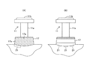
さらに、本発明の実施にあたっては、上記実施形態およびその変形例に限定されるものではなく、本発明の目的を逸脱しない限りにおいて種々の変形も可能である。例えば、図6(A)に示すように、第1演奏ピストン11に対応したリング17を構成する樹脂内に、光を反射する小さな反射体、気泡17aなどを多数混入させて、発光素子21からの光を乱反射させて、リング17全体が発光しているように見えるようにしてもよい。また、図6(B)に示すように、リング17の下方に複数の発光素子21を設けるようにしてもよい。なお、これらの変形例は、第2および第3演奏ピストン12,13に対応したリング18,19にも適用できるものである。
【0041】
また、第1〜第3演奏ピストン11〜13に対応した発光素子21〜23の点灯色を異ならせるようにしてもよい。上記実施形態においては、第1〜第3演奏ピストン11〜13の近傍に位置するリング17〜19を発光させるようにしたが、第1〜第3演奏ピストン11〜13自体を発光させるようにしてもよい。この場合、第1〜第3演奏ピストン11〜13のロッド11a〜13aおよび操作部11b〜13bの少なくともいずれか一方を透明または半透明の樹脂で構成し、同樹脂内に発光素子21〜23からの光を導くようにすればよい。
【0042】
また、上記実施形態およびその変形例においては、第1〜第3演奏ピストン11〜13のうちで操作すべき演奏ピストンを発光素子21〜23の点灯によって視覚的に表示するようにした。しかし、これに代えまたは加えて、操作すべき演奏ピストンを上方または下方に若干変位させ、または同ピストンを振動させて、操作すべき演奏ピストンを演奏者に対して触覚的に認識させるような演奏指示を行うようにしてもよい。この場合、図1および図2に破線で示すように、グリップ14〜16内に、第1〜第2演奏ピストン11〜12を駆動する小型電磁アクチュエータ、小型圧電アクチュエータなどの駆動装置61〜63をそれぞれ内蔵させるとともに、発光制御回路37に代えまたは加えて、操作すべき演奏ピストンを表すデータに基づいて前記駆動装置を駆動制御する駆動制御回路を設ければよい。
【0043】
また、上記実施形態では、演奏操作子として第1〜第3演奏ピストン11〜13を採用したが、これらの第1〜第3演奏ピストン11〜13に代えて、単なる操作スイッチ、タッチスイッチなどで構成されて、発生楽音の音高を決定するための種々の演奏操作子を利用できる。また、演奏操作子の数に関しても、2以上の適宜の整数を採用できる。要するに、本発明は、複数の演奏操作子の操作の組み合わせに応じて発生楽音の音高を決定する種々の楽器に適用できるものである。
【0044】
また、上記実施形態の空気振動検出器24に代えて、人体の「のど」に接触させて振動を検出する骨伝導ピックアップ装置を用いて、この検出した「のど」の振動の周波数を検出して、同検出周波数をコンピュータ本体部35のプログラム処理による音高判定処理部54に導いて、同音高判定処理部54による音高判定処理に利用するようにしてもよい。これにより、声帯を悪くして音声を発生できない者でも、上記実施形態のような口空気流型楽器の演奏が可能になる。
【0045】
さらに、楽器の外形形状および発生楽音の音色に関しても、本発明は、ホルンなどの他の管楽器の楽器形状、またはその他の自然楽器の形状を模擬するとともに、これらの楽器の音色の楽音を発生するようにした電子楽器にも適用される。また、電子的に楽音を発生させる以外の楽器にも適用できる。
【図面の簡単な説明】
【図1】 本発明の一実施形態に係る楽器の外観を示す概略側面図である。
【図2】 演奏ピストンおよびグリップを拡大して示す図1の部分拡大図である。
【図3】 図1の楽器に内蔵されている電気回路装置のブロック図である。
【図4】 図3のコンピュータ本体部で実行されるプログラムを機能的に示す機能ブロック図である。
【図5】 音高と運指との関係を示す運指図である。
【図6】 (A)および(B)は、上記実施形態の変形例に係る演奏ピストン部を示す部分図である。
【符号の説明】
10…ハウジング、11〜13…第1〜第3演奏ピストン(演奏操作子)、14〜16…グリップ、17〜19…リング(演奏ガイド手段)、21〜23…発光素子(演奏ガイド手段)、24…空気振動検出器、34…楽音信号発生回路、35…コンピュータ本体部、36…メモリ装置、37…発光制御回路(ガイド制御手段)、41…外部機器用インターフェース回路(外部入力手段)、42…通信用インターフェース回路(外部入力手段)、51…演奏データ読み出し処理部、52…運指変換処理部(変換手段)、53…音高候補抽出処理部、54…音高判定処理部、61〜63…駆動装置(演奏ガイド手段)。[0001]
BACKGROUND OF THE INVENTION
The present invention relates to a musical instrument that includes a plurality of performance operators, such as a trumpet or a horn, and that determines the pitch of a generated musical sound according to a combination of operations of the plurality of performance operators.
[0002]
[Prior art]
In recent years, musical instruments that electronically generate musical sounds by simulating wind instruments such as saxophones and recorders have appeared. Similar to wind instruments such as saxophones and recorders, this type of musical instrument is provided with a plurality of performance operators that are pressed by the performer, and the pitch of the musical tone generated according to the pressing operations of the plurality of performance operators. Is to be decided.
[0003]
[Problems to be solved by the invention]
In the above wind instrument or electronic wind instrument, it is relatively easy to specify a pitch for a performance operation. However, in a wind instrument such as a trumpet or horn, the pitch designation is slightly complicated because the pitch of the generated musical tone is determined by the combination of pressing operations of the three piston operators. That is, it is difficult to perform a smooth musical instrument performance as compared to a musical instrument that operates a single operator (single key) to specify a pitch, such as a keyboard musical instrument. Therefore, for those who have not mastered the performance of wind instruments such as trumpet and horn, there is a problem that this kind of instrument cannot be enjoyed easily and it is difficult to grasp the opportunity to practice.
[0004]
SUMMARY OF THE INVENTION
The present invention has been made to cope with the above problems, and its purpose is to easily enjoy the performance of a musical instrument in which the pitch of the generated musical sound is determined according to the combination of operations of a plurality of performance operators. It is to be able to practice the same instrument easily.
[0005]
In order to achieve the above object, the structural features of the present invention are:Entry into the housing is possiblepluralPlaying pistonWith the same multiplePlaying pistonFor musical instruments in which the pitch of the generated musical tone is determined according to the combination ofPlaying pistonA combination ofIn order to instruct the player, a transparent ring is provided at each of the entrance holes of the plurality of performance pistons into the housing, and a light emitter is placed in the housing so as to face the ring.It is in providing.In this case, the external shape of the musical instrument is, for example, a wind musical instrument shape.
[0006]
In the feature of the present invention configured as described above, the player can recognize the combination of the plurality of performance pistons to be operated by the light emission of the ring corresponding to the plurality of performance pistons. Therefore, according to the features of the present invention, even those who have not mastered this kind of musical instrument performance can easily determine the pitch of the generated musical tone by following the instructions, and this kind of musical instrument performance can be easily performed. You will be able to enjoy the instrument and practice the instrument easily.
[0007]
Another feature of the present invention is that in this type of musical instrument, pitch data representing a pitch is further input, and the input pitch data is a plurality of pitches corresponding to the pitch represented by the pitch data. There are provided conversion means for converting into combination data representing a combination of operation of the performance piston, and light emission control means for controlling light emission of the light emitting element in accordance with the combination data converted by the conversion means.
[0008]
In another feature of the present invention configured as described above, the player is instructed by the conversion means and the light emission control means about the combination of a plurality of performance pistons to be operated only by inputting pitch data representing the pitch. The Therefore, the usability of the performance guide function of this instrument is improved.
[0009]
Further, according to another feature of the present invention, in this type of musical instrument, based on external input means capable of inputting performance data representing music from the outside, and performance data input from the outside by the external input means, A light emission control means for controlling light emission of the light emitting element is provided. In this case, the external input means inputs performance data from various external music devices such as a sequencer, an electronic musical instrument, and a personal computer, or inputs performance data from a server via a communication line such as the Internet.
[0010]
In another feature of the present invention configured as described above, performance data representing various musical pieces can be easily obtained via the external input means, and a performance to be operated by the performer based on the obtained performance data. The combination of pistons can be indicated. Therefore, the performer can enjoy the performance of various music pieces and can practice the performance of various music pieces.
[0011]
Further, another structural feature of the present invention is that the combination of a plurality of performance pistons to be operated by the player is also indicated by instructing the player by displacing the plurality of performance pistons. A plurality of driving devices for displacing the plurality of performance pistons are provided. According to this, the player can recognize the combination of a plurality of performance pistons to be operated even by the displacement of the performance piston.
[0012]
DETAILED DESCRIPTION OF THE INVENTION
Hereinafter, an embodiment of the present invention will be described with reference to the drawings. FIG. 1 is a schematic side view showing the appearance of a musical instrument according to the present invention.
[0013]
This musical instrument includes a
[0014]
As shown in FIGS. 1 and 2, these first to
[0015]
[0016]
An
[0017]
Next, the electric circuit device will be described with reference to the block diagram of FIG. 3. The electric circuit device includes an audio signal input circuit 31, a
[0018]
The audio signal input circuit 31 includes a
[0019]
The computer
[0020]
Further, an external
[0021]
Prior to describing the specific operation of the musical instrument configured as described above, a method for playing this musical instrument will be briefly described. The player holds the musical instrument by gripping the
[0022]
Then, as described above, in a state where the first to
[0023]
The pitch designation will be described with reference to FIG. 5. In the left column labeled “Performance Piston” in the figure, the non-operation state and the operation state of the first to
[0024]
Further, the arrow below the circle in the figure indicates the allowable range of frequency deviation with respect to the generated musical sound of the audio signal input from the
[0025]
Next, a specific operation of the musical instrument configured as described above will be described with reference to the functional block diagram of FIG. The computer processing unit in this functional block diagram functionally represents the program processing of the computer
[0026]
By executing the program of the computer
[0027]
The fingering table stores data indicating the relationship between the pitch of the musical tone to be generated and the combination of the first to
[0028]
The fingering
[0029]
Since the player can recognize the combination of the first to
[0030]
The pitch data, key-on data, key-off data, etc. read by the performance data read processing
[0031]
Next, a case where the performer presses the first to
[0032]
The pitch candidate table 53a stores data representing the relationship between combinations of operations of the first to
[0033]
Therefore, the pitch candidate
[0034]
In addition to the pitch candidate data, the pitch
[0035]
On the other hand, the sound generation control data
[0036]
Further, data representing the operation state of the first to
[0037]
This control means that the
[0038]
In addition, a late arrival priority circuit is provided in the light
[0039]
As described above, in the explanation of the operation of the musical instrument according to the present embodiment, the lighting control of the
[0040]
Furthermore, in carrying out the present invention, the present invention is not limited to the above-described embodiment and its modifications, and various modifications can be made without departing from the object of the present invention. For example, as shown in FIG. 6A, a large number of small reflectors that reflect light, bubbles 17a, etc. are mixed in the resin constituting the
[0041]
Moreover, you may make it vary the lighting color of the light emitting elements 21-23 corresponding to the 1st-3rd performance pistons 11-13. In the above embodiment, the
[0042]
Moreover, in the said embodiment and its modification, the performance piston which should be operated among the 1st-3rd performance pistons 11-13 was displayed visually by lighting of the light emitting elements 21-23. However, instead of or in addition to this, the performance piston to be operated is slightly displaced upward or downward, or the piston is vibrated so that the player can tactilely recognize the performance piston to be operated. An instruction may be given. In this case, as indicated by broken lines in FIGS. 1 and 2, driving
[0043]
Moreover, in the said embodiment, although the 1st-3rd performance pistons 11-13 were employ | adopted as a performance operator, it replaced with these 1st-3rd performance pistons 11-13, and a simple operation switch, a touch switch, etc. It is possible to use various performance operators for determining the pitch of the generated musical sound. Also, regarding the number of performance operators, an appropriate integer of 2 or more can be adopted. In short, the present invention can be applied to various musical instruments that determine the pitches of generated musical sounds according to combinations of operations of a plurality of performance operators.
[0044]
Further, instead of the
[0045]
Further, regarding the external shape of the musical instrument and the tone of the generated musical tone, the present invention simulates the shape of another wind instrument such as a horn or the shape of other natural musical instruments and generates the musical tone of the tone of these musical instruments. It is also applied to the electronic musical instruments. It can also be applied to musical instruments other than electronically generating musical sounds.
[Brief description of the drawings]
FIG. 1 is a schematic side view showing an external appearance of a musical instrument according to an embodiment of the present invention.
FIG. 2 is a partially enlarged view of FIG. 1 showing an enlarged performance piston and grip.
3 is a block diagram of an electric circuit device built in the musical instrument of FIG. 1. FIG.
4 is a functional block diagram functionally showing a program executed in the computer main unit of FIG. 3. FIG.
FIG. 5 is a fingering diagram showing the relationship between pitch and fingering.
6A and 6B are partial views showing a performance piston portion according to a modification of the embodiment. FIG.
[Explanation of symbols]
DESCRIPTION OF
Claims (5)
演奏者によって操作されるべき複数の演奏ピストンの組み合わせを演奏者に指示するために、前記複数の演奏ピストンの前記ハウジングへの侵入口に透明のリングをそれぞれ設けるとともに、前記リングに対向させて前記ハウジング内に発光体をそれぞれ設けたことを特徴とする楽器。 In a musical instrument having a plurality of performance pistons that are allowed to advance and retract into the housing, and the pitch of the generated musical sound is determined according to a combination of operations of the plurality of performance pistons ,
In order to instruct the player of a combination of a plurality of performance pistons to be operated by the performer , a transparent ring is provided at each of the entrance holes of the plurality of performance pistons to the housing, and the ring is opposed to the ring. A musical instrument characterized in that a light emitter is provided in each housing .
音高を表す音高データを入力して、同入力した音高データを同音高データにより表された音高に対応した複数の演奏ピストンの操作の組み合わせを表す組み合わせデータに変換する変換手段と、
前記変換手段によって変換された組み合わせデータに応じて、前記発光素子の発光を制御する発光制御手段とを設けた楽器。The musical instrument according to claim 1 or 2 , further comprising inputting pitch data representing a pitch, and operating the plurality of performance pistons corresponding to the pitch represented by the pitch data. A conversion means for converting into combination data representing a combination of
A musical instrument provided with light emission control means for controlling light emission of the light emitting element in accordance with the combination data converted by the conversion means.
楽曲を表す演奏データを外部から入力することが可能な外部入力手段と、
前記外部入力手段によって外部から入力した演奏データに基づいて、前記発光素子の発光を制御する発光制御手段とを設けた楽器。The instrument according to claim 1 or 2 , further comprising external input means capable of inputting performance data representing music from outside,
A musical instrument provided with light emission control means for controlling light emission of the light emitting element based on performance data input from the outside by the external input means.
演奏者によって操作されるべき複数の演奏ピストンの組み合わせを、前記複数の演奏ピストンを変位させることによっても演奏者に指示するために、さらに、前記複数の演奏ピストンをそれぞれ変位させる複数の駆動装置を設けた楽器。In the musical instrument according to any one of claims 1 to 4,
In order to instruct the player of a combination of a plurality of performance pistons to be operated by the performer by displacing the plurality of performance pistons, a plurality of drive devices that respectively displace the plurality of performance pistons A set of instruments.
Priority Applications (2)
| Application Number | Priority Date | Filing Date | Title |
|---|---|---|---|
| JP2002133328A JP4195232B2 (en) | 2002-05-08 | 2002-05-08 | Musical instrument |
| US10/431,216 US6815599B2 (en) | 2002-05-08 | 2003-05-07 | Musical instrument |
Applications Claiming Priority (1)
| Application Number | Priority Date | Filing Date | Title |
|---|---|---|---|
| JP2002133328A JP4195232B2 (en) | 2002-05-08 | 2002-05-08 | Musical instrument |
Publications (2)
| Publication Number | Publication Date |
|---|---|
| JP2003330456A JP2003330456A (en) | 2003-11-19 |
| JP4195232B2 true JP4195232B2 (en) | 2008-12-10 |
Family
ID=29397416
Family Applications (1)
| Application Number | Title | Priority Date | Filing Date |
|---|---|---|---|
| JP2002133328A Expired - Fee Related JP4195232B2 (en) | 2002-05-08 | 2002-05-08 | Musical instrument |
Country Status (2)
| Country | Link |
|---|---|
| US (1) | US6815599B2 (en) |
| JP (1) | JP4195232B2 (en) |
Families Citing this family (31)
| Publication number | Priority date | Publication date | Assignee | Title |
|---|---|---|---|---|
| JP3858899B2 (en) * | 2003-03-20 | 2006-12-20 | ヤマハ株式会社 | Stringed electronic musical instrument |
| JP4448378B2 (en) * | 2003-07-30 | 2010-04-07 | ヤマハ株式会社 | Electronic wind instrument |
| JP2005049439A (en) * | 2003-07-30 | 2005-02-24 | Yamaha Corp | Electronic musical instrument |
| JP5023528B2 (en) * | 2006-03-24 | 2012-09-12 | ヤマハ株式会社 | Wind instrument support structure |
| JP4752562B2 (en) * | 2006-03-24 | 2011-08-17 | ヤマハ株式会社 | Key drive device and keyboard instrument |
| US7723605B2 (en) | 2006-03-28 | 2010-05-25 | Bruce Gremo | Flute controller driven dynamic synthesis system |
| US7557283B1 (en) * | 2007-05-30 | 2009-07-07 | Moncrief Frank N | Guitar slide |
| US8199033B2 (en) | 2007-07-06 | 2012-06-12 | Pacinian Corporation | Haptic keyboard systems and methods |
| US7741979B2 (en) | 2007-07-06 | 2010-06-22 | Pacinian Corporation | Haptic keyboard systems and methods |
| US8248277B2 (en) * | 2007-07-06 | 2012-08-21 | Pacinian Corporation | Haptic keyboard systems and methods |
| US8310444B2 (en) | 2008-01-29 | 2012-11-13 | Pacinian Corporation | Projected field haptic actuation |
| US8294600B2 (en) * | 2008-02-15 | 2012-10-23 | Cody George Peterson | Keyboard adaptive haptic response |
| US8203531B2 (en) | 2008-03-14 | 2012-06-19 | Pacinian Corporation | Vector-specific haptic feedback |
| US20090253509A1 (en) * | 2008-04-02 | 2009-10-08 | Howard Tripp | Illuminated game controller |
| US8760413B2 (en) * | 2009-01-08 | 2014-06-24 | Synaptics Incorporated | Tactile surface |
| US8624839B2 (en) * | 2009-10-15 | 2014-01-07 | Synaptics Incorporated | Support-surface apparatus to impart tactile feedback |
| US10068728B2 (en) * | 2009-10-15 | 2018-09-04 | Synaptics Incorporated | Touchpad with capacitive force sensing |
| US8912458B2 (en) | 2011-01-04 | 2014-12-16 | Synaptics Incorporated | Touchsurface with level and planar translational travel responsiveness |
| US8309870B2 (en) | 2011-01-04 | 2012-11-13 | Cody George Peterson | Leveled touchsurface with planar translational responsiveness to vertical travel |
| US8847890B2 (en) | 2011-01-04 | 2014-09-30 | Synaptics Incorporated | Leveled touchsurface with planar translational responsiveness to vertical travel |
| US9324515B2 (en) | 2012-08-06 | 2016-04-26 | Synaptics Incorporated | Touchsurface assembly utilizing magnetically enabled hinge |
| US9218927B2 (en) | 2012-08-06 | 2015-12-22 | Synaptics Incorporated | Touchsurface assembly with level and planar translational responsiveness via a buckling elastic component |
| US9040851B2 (en) | 2012-08-06 | 2015-05-26 | Synaptics Incorporated | Keycap assembly with an interactive spring mechanism |
| US9177733B2 (en) | 2012-08-06 | 2015-11-03 | Synaptics Incorporated | Touchsurface assemblies with linkages |
| JP5857930B2 (en) * | 2012-09-27 | 2016-02-10 | ヤマハ株式会社 | Signal processing device |
| US9384919B2 (en) | 2013-03-14 | 2016-07-05 | Synaptics Incorporated | Touchsurface assembly having key guides formed in a sheet metal component |
| US9213372B2 (en) | 2013-04-19 | 2015-12-15 | Synaptics Incorporated | Retractable keyboard keys |
| US9640152B2 (en) * | 2015-01-23 | 2017-05-02 | Carl J. Allendorph, LLC | Electronic mute for musical instrument |
| US10818277B1 (en) * | 2019-09-30 | 2020-10-27 | Artinoise S.R.L. | Enhanced electronic musical wind instrument |
| CN112863295B (en) * | 2021-01-13 | 2022-10-25 | 西安石油大学 | Saxophone teaching is with supplementary intonation orthotic devices of intelligence |
| KR102433036B1 (en) * | 2021-08-11 | 2022-08-18 | 김충국 | Practice device for wind instrument |
Family Cites Families (8)
| Publication number | Priority date | Publication date | Assignee | Title |
|---|---|---|---|---|
| US2225084A (en) * | 1939-03-20 | 1940-12-17 | Glen O Pierce | Instruction device for band instruments |
| JPS61176987A (en) | 1985-01-31 | 1986-08-08 | ヤマハ株式会社 | Key display unit for electronic musical instrument |
| US4685373A (en) * | 1986-04-07 | 1987-08-11 | Juan Novo | Musical instrument |
| JP2707853B2 (en) | 1991-03-01 | 1998-02-04 | ヤマハ株式会社 | Key press indicating device |
| JP3484719B2 (en) * | 1993-04-02 | 2004-01-06 | ヤマハ株式会社 | Performance guide device with voice input function and performance guide method |
| JP2950138B2 (en) * | 1994-03-23 | 1999-09-20 | ヤマハ株式会社 | Fingering information analyzer and electronic musical instrument using the same |
| US6211452B1 (en) * | 1994-11-10 | 2001-04-03 | Yamaha Corporation | Electronic musical instrument having a function of dividing performance information into phrases and displaying keys to be operated for each phrase |
| US6225544B1 (en) * | 1999-02-26 | 2001-05-01 | Kevin Sciortino | Music instrument illuminator and positioning aid |
-
2002
- 2002-05-08 JP JP2002133328A patent/JP4195232B2/en not_active Expired - Fee Related
-
2003
- 2003-05-07 US US10/431,216 patent/US6815599B2/en not_active Expired - Fee Related
Also Published As
| Publication number | Publication date |
|---|---|
| US6815599B2 (en) | 2004-11-09 |
| US20030209131A1 (en) | 2003-11-13 |
| JP2003330456A (en) | 2003-11-19 |
Similar Documents
| Publication | Publication Date | Title |
|---|---|---|
| JP4195232B2 (en) | Musical instrument | |
| US7321094B2 (en) | Electronic musical instrument | |
| US20040244566A1 (en) | Method and apparatus for producing acoustical guitar sounds using an electric guitar | |
| US20050150361A1 (en) | Musical instrument performing artistic visual expression and controlling system incorporated therein | |
| JP4448378B2 (en) | Electronic wind instrument | |
| EP1302927B1 (en) | Chord presenting apparatus and method | |
| US4757736A (en) | Electronic musical instrument having rhythm-play function based on manual operation | |
| JP2001066982A (en) | Performance training device, keyboard instrument, and fingering training device | |
| JP4433065B2 (en) | Musical instrument | |
| JP4743341B2 (en) | Keyboard instrument | |
| JP2003288077A (en) | Music data output system and program | |
| JP3705175B2 (en) | Performance control device | |
| JP4131220B2 (en) | Chord playing instrument | |
| JP2005049421A (en) | Electronic musical instrument | |
| JP3912210B2 (en) | Musical instruments and performance assist devices | |
| WO2018159829A1 (en) | Playing support device and method | |
| JP3991892B2 (en) | Electronic musical instruments | |
| JP3620366B2 (en) | Electronic keyboard instrument | |
| JP3714240B2 (en) | Electronic musical instrument with performance support function | |
| JP3705174B2 (en) | Performance control device | |
| JP2005049420A (en) | Electronic musical instrument | |
| Trail | Non-invasive gesture sensing, physical modeling, machine learning and acoustic actuation for pitched percussion | |
| JP2000172253A (en) | Electronic musical instrument | |
| JP4144459B2 (en) | Musical instrument | |
| JPH08202256A (en) | Music teaching system |
Legal Events
| Date | Code | Title | Description |
|---|---|---|---|
| A621 | Written request for application examination |
Free format text: JAPANESE INTERMEDIATE CODE: A621 Effective date: 20040421 |
|
| A131 | Notification of reasons for refusal |
Free format text: JAPANESE INTERMEDIATE CODE: A131 Effective date: 20061121 |
|
| A521 | Written amendment |
Free format text: JAPANESE INTERMEDIATE CODE: A523 Effective date: 20070116 |
|
| A02 | Decision of refusal |
Free format text: JAPANESE INTERMEDIATE CODE: A02 Effective date: 20070410 |
|
| A01 | Written decision to grant a patent or to grant a registration (utility model) |
Free format text: JAPANESE INTERMEDIATE CODE: A01 |
|
| A61 | First payment of annual fees (during grant procedure) |
Free format text: JAPANESE INTERMEDIATE CODE: A61 Effective date: 20080925 |
|
| R150 | Certificate of patent or registration of utility model |
Free format text: JAPANESE INTERMEDIATE CODE: R150 |
|
| FPAY | Renewal fee payment (event date is renewal date of database) |
Free format text: PAYMENT UNTIL: 20111003 Year of fee payment: 3 |
|
| FPAY | Renewal fee payment (event date is renewal date of database) |
Free format text: PAYMENT UNTIL: 20111003 Year of fee payment: 3 |
|
| FPAY | Renewal fee payment (event date is renewal date of database) |
Free format text: PAYMENT UNTIL: 20121003 Year of fee payment: 4 |
|
| FPAY | Renewal fee payment (event date is renewal date of database) |
Free format text: PAYMENT UNTIL: 20121003 Year of fee payment: 4 |
|
| FPAY | Renewal fee payment (event date is renewal date of database) |
Free format text: PAYMENT UNTIL: 20131003 Year of fee payment: 5 |
|
| LAPS | Cancellation because of no payment of annual fees |