JP4193665B2 - Digital watermarking method for binary images - Google Patents
Digital watermarking method for binary images Download PDFInfo
- Publication number
- JP4193665B2 JP4193665B2 JP2003343917A JP2003343917A JP4193665B2 JP 4193665 B2 JP4193665 B2 JP 4193665B2 JP 2003343917 A JP2003343917 A JP 2003343917A JP 2003343917 A JP2003343917 A JP 2003343917A JP 4193665 B2 JP4193665 B2 JP 4193665B2
- Authority
- JP
- Japan
- Prior art keywords
- pixel
- information
- watermark
- modified
- image
- Prior art date
- Legal status (The legal status is an assumption and is not a legal conclusion. Google has not performed a legal analysis and makes no representation as to the accuracy of the status listed.)
- Expired - Fee Related
Links
Images


Classifications
-
- G—PHYSICS
- G06—COMPUTING; CALCULATING OR COUNTING
- G06T—IMAGE DATA PROCESSING OR GENERATION, IN GENERAL
- G06T1/00—General purpose image data processing
- G06T1/0021—Image watermarking
- G06T1/0028—Adaptive watermarking, e.g. Human Visual System [HVS]-based watermarking
-
- G—PHYSICS
- G06—COMPUTING; CALCULATING OR COUNTING
- G06T—IMAGE DATA PROCESSING OR GENERATION, IN GENERAL
- G06T2201/00—General purpose image data processing
- G06T2201/005—Image watermarking
- G06T2201/0051—Embedding of the watermark in the spatial domain
-
- G—PHYSICS
- G06—COMPUTING; CALCULATING OR COUNTING
- G06T—IMAGE DATA PROCESSING OR GENERATION, IN GENERAL
- G06T2201/00—General purpose image data processing
- G06T2201/005—Image watermarking
- G06T2201/0061—Embedding of the watermark in each block of the image, e.g. segmented watermarking
-
- G—PHYSICS
- G06—COMPUTING; CALCULATING OR COUNTING
- G06T—IMAGE DATA PROCESSING OR GENERATION, IN GENERAL
- G06T2201/00—General purpose image data processing
- G06T2201/005—Image watermarking
- G06T2201/0083—Image watermarking whereby only watermarked image required at decoder, e.g. source-based, blind, oblivious
Description
本発明は、任意の情報を二値画像に埋め込み、それを検出する、二値画像用の電子透かし技術に関係する。 The present invention relates to a digital watermark technique for a binary image that embeds arbitrary information in a binary image and detects it.
二値画像用電子透かしとは、文書、表、地図などといった二値画像のデジタルデータに、改変が目立ちにくい箇所の画素の輝度値を反転させることで著作権IDなどの情報を埋め込み、二値画像の著作権を保護する技術である。 Digital image watermark for binary images embeds information such as copyright IDs by reversing the luminance values of pixels in places that are difficult to modify in digital data of binary images such as documents, tables, maps, etc. This technology protects the copyright of images.
二値画像への情報埋め込み方法に対して実用面から以下の要求がある。 There are the following demands from the practical aspect for the information embedding method in the binary image.
(1) 文字だけからなる文書に限らず一般の二値画像に適用可能。 (1) Applicable to general binary images as well as documents consisting only of characters.
(2) 大量の情報を埋め込まない限り、透かし挿入による改変が知覚されない。あるいは知覚できたとしても画像認知の妨害にならない。 (2) Unless a large amount of information is embedded, alteration by watermark insertion is not perceived. Or even if it can be perceived, it does not interfere with image recognition.
(3) 拡大・縮小などの画像処理が施された場合や、印刷された紙からも、挿入された情報が正常に検出できる。 (3) The inserted information can be normally detected when image processing such as enlargement / reduction is performed or from printed paper.
(4) 埋め込む情報量を調節可能。 (4) The amount of information to be embedded can be adjusted.
文字だけからなる二値画像用電子透かしの技術として、文字間隔、行間を微妙に変更することで情報を秘匿する技術が知られている。例えば、非特許文献1を参照。 A technique for concealing information by slightly changing the character spacing and line spacing is known as a technique for digital watermarking for binary images consisting only of characters. For example, see Non-Patent Document 1.
一般の二値画像に適用可能な従来技術として、透かし情報に対応する特殊なパターンを背景の白部分に直接書き込む方法が知られている。例えば、次の非特許文献2を参照。さらに、画像の平坦部より改変が目立ちにくい輪郭部分だけに微細な変更を施すことで透かし情報を挿入する、非特許文献3が知られている。
As a conventional technique applicable to a general binary image, a method of directly writing a special pattern corresponding to watermark information on a white portion of a background is known. For example, see the following non-patent
非特許文献1の技術では文字の位置情報を変更するので、印刷した紙からも正しく情報が復元でき、要求(3)が満たされる。しかしこの技術は文字だけからなる二値画像にしか適用できないため、上記の要求(1)が満たされない。また、文字間隔などを微妙に変更することで画面のレイアウトが変わるため要求(2)が満たされず、さらに、画像中にある文字の個数で埋め込める透かし情報の量も変わってしまう。従って、この技術は(4)も満足しない。 In the technique of Non-Patent Document 1, the character position information is changed, so that the information can be correctly restored from the printed paper, and the request (3) is satisfied. However, since this technique can only be applied to binary images consisting only of characters, the above requirement (1) is not satisfied. Further, since the screen layout is changed by slightly changing the character spacing, the requirement (2) is not satisfied, and the amount of watermark information that can be embedded by the number of characters in the image also changes. Therefore, this technique does not satisfy (4).
非特許文献2の技術では、埋め込みたい情報に対応する特殊なパターンを背景に直接書き込むことで、印刷した紙からも正しく情報が検出できる。従って要求(3)が満足される。また、一般の二値画像に適用可能であるため、要求(1)も満足される。
しかし、この技術では、情報が背景に直接書き込まれるので、透かし埋め込みが容易に知覚でき、上記の要求(2)が満たされない。また、背景部の面積に応じて埋め込む情報量が変わってしまうため、要求(4)も満たされない。
In the technique of Non-Patent
However, in this technique, since information is directly written in the background, watermark embedding can be easily perceived, and the above requirement (2) is not satisfied. Further, since the amount of information to be embedded changes according to the area of the background portion, the request (4) is not satisfied.
非特許文献3の技術は一般の二値画像に適用可能であるため、要求(1)が満たされ、さらに、輪郭部分だけに改変を施すために、凹凸した輪郭成分を多く含むような画像に適用した場合には、要求(2)が満足される。また、この技術は、画像処理にある程度の耐性を有することが実証されているため、要求(3)を満たす。さらに、変更する画素の数を調節することで埋め込む情報量も調節できるため、要求(4)も満たす。
Since the technique of Non-Patent
しかし非特許文献3の技術では、透かし埋め込みによって輪郭部分に凹凸が生じるために、その分画質が劣化してしまう。従って滑らかな輪郭成分しか含まないような画像に適用した場合には、輪郭に凹凸が生じることで、改変が画像認知の妨害となる場合が多々ある。このような画像の場合には要求(2)が満足されない。さらに、この技術では、画像中に輪郭部分が少ない場合、透かし情報を埋め込めない場合がある。
However, in the technique of Non-Patent
また、上記の要求(4)を満たすためには、例えば画像処理を施されても透かし情報が除去されないように、かつ、二値画像の輪郭部分の多さなどといった原画の構造に依存せず、予想される画像処理に応じて埋め込む情報量を調節できることが要求される。しかしこのような調整は、従来の二値画像用電子透かしすべてにおいて困難である。 In order to satisfy the above requirement (4), for example, watermark information is not removed even if image processing is performed, and it does not depend on the structure of the original image such as the number of contour portions of the binary image. Therefore, it is required that the amount of information to be embedded can be adjusted according to the expected image processing. However, such adjustment is difficult for all conventional digital watermarks for binary images.
以上の通り、従来の二値画像用電子透かし技術では、要求(1)〜(4)すべてを同時に満たすことができない。 As described above, the conventional binary image digital watermark technology cannot satisfy all the requirements (1) to (4) at the same time.
本発明は、上記要求(1)〜(4)すべてを高い程度で満足する二値画像用電子透かし技術を提供する。 The present invention provides a binary image digital watermark technique that satisfies all the above requirements (1) to (4) to a high degree.
本発明は、輪郭部分にも、改変が目立ちやすい箇所とそうでない箇所とに分類されることを応用している。例えば、もともと凸凹がある輪郭部分には、多少の改変を施してもその改変が知覚されることはないが、もともと整った線分に対する改変は目立つ。 The present invention applies that the contour portion is classified into a portion that is easily noticeable and a portion that is not so prominent. For example, the contour portion that originally has the unevenness is not perceived even if a slight modification is made, but the modification to the originally arranged line segment is conspicuous.
本発明は、改変の目立ちにくい箇所を選定して、その部分を積極的に改変することで、画質をできるだけ維持したまま、多くの情報を埋め込むことを可能にする。 The present invention makes it possible to embed a large amount of information while maintaining the image quality as much as possible by selecting a portion that is not easily noticeable and actively changing the portion.
具体的には、透かしを埋め込むために、まず、改変が最も目立ちにくい画素だけを選定して反転する。もし選定した反転個数が少なく、要求される透かし情報を埋め込むことができなかったら、次に目立ちにくい画素を追加して反転させていく。このような操作を繰り返すことで、従来技術と比べて画質をできるだけ維持したまま、より多くの情報を埋め込むことが可能とする。 Specifically, in order to embed a watermark, first, only the pixels that are least noticeable are selected and inverted. If the selected number of inversions is small and the required watermark information cannot be embedded, the next inconspicuous pixel is added and inverted. By repeating such an operation, it is possible to embed more information while maintaining the image quality as much as possible as compared with the prior art.
また、輪郭部分のみを改変して情報を埋め込む従来技術では、画像中にある輪郭部分の量に応じて挿入情報量に限界があった。本発明は、輪郭部分だけの改変だけでは所望の情報量に達しなかった場合、輪郭部分だけではなく、背景部分にも情報を書き込むことにより、より多くの情報を埋め込むことを可能とする。 Further, in the prior art in which only the contour portion is modified and information is embedded, there is a limit to the amount of information to be inserted according to the amount of the contour portion in the image. The present invention makes it possible to embed more information by writing information not only in the contour portion but also in the background portion when the desired amount of information is not reached by only modifying the contour portion.
以上のように、本発明は、人間の視覚特性に基づいて改変の目立ちやすさ、優先順位を定義し、できるだけ高い順位の画素だけを反転させることで、画質をできるだけ維持したまま多くの情報を埋め込むことを特徴とする。 As described above, the present invention defines the visibility and priority of modification based on human visual characteristics and inverts only the highest-ranked pixels as much as possible so that a large amount of information can be obtained while maintaining the image quality as much as possible. It is characterized by embedding.
その結果、埋め込む情報量をより広い範囲で調節可能となり、要求(4)を満たすことが可能になる。 As a result, the amount of information to be embedded can be adjusted in a wider range, and the requirement (4) can be satisfied.
本発明は輪郭および背景部分を改変することから、文字だけではない一般の二値画像に適用可能である。従って、上記の要求(1)を満たす。また、できるだけ目立ちにくい箇所のみを選定して改変するために、埋め込み情報量に応じた最善の画質が維持され、要求(2),(4)が満たされる。また、本発明は輪郭部分のみを改変する非特許文献3に記載された技術を内包するため、この技術で実証された要求(3)も満足される。
Since the present invention modifies the outline and the background portion, it can be applied to general binary images that are not limited to characters. Therefore, the above requirement (1) is satisfied. In addition, since only the parts that are as inconspicuous as possible are selected and modified, the best image quality corresponding to the amount of embedded information is maintained, and the requirements (2) and (4) are satisfied. Further, since the present invention includes the technique described in
本発明の実施に当たっては、人間の視覚特性に基づいて改変の目立ちやすさ、優先順位を定義しなければならない。 In implementing the present invention, it is necessary to define the visibility and priority of modification based on human visual characteristics.
二値画像の改変の目立ちやすさに関しては、古くから認知科学の立場から多くの事実が解明されている。例えば、文献
淀川英司、東倉洋一、中根一成:「視聴覚の認知科学」、電子情報通信学会編pp.50-52 (1998)
によれば、人間の視覚は、二値画像を不規則部分や連続性などの要因に基づいて注視するとされている。このことから、透かし埋め込みによって背景にノイズが生じたり、連続した線分に切れ目が生じたりした場合、そのような改変は直ちに知覚され、画質劣化をまねくと考えられる。
Many facts have been elucidated from the standpoint of cognitive science since long ago. For example, Eiji Kajikawa, Yoichi Higashikura, Kazunari Nakane: “Cognitive Science of Audiovisual Technology”, IEICE pp.50-52 (1998)
According to the above, it is said that human vision gazes at a binary image based on factors such as irregular parts and continuity. For this reason, if noise is generated in the background due to watermark embedding, or a break occurs in a continuous line segment, such modification is immediately perceived, and it is considered that image quality deterioration is caused.
また、文献
淀川英司、東倉洋一、中根一成:「視聴覚の認知科学」、電子情報通信学会編pp.9-13 (1998)
では、人間の目は、網膜に映った像の輪郭部分を、その方向にそって平滑化してから認識すると述べられている(方向選択性という)。従って、人間の目は輪郭のにじみや凹凸に敏感で、逆に、輪郭部分をその方向に平滑化するように改変を施した場合、そのような改変は人間の目に画質劣化を引き起こさないと考えられる。
Also, Eiji Sasakawa, Yoichi Higashikura, Kazunari Nakane: “Cognitive Science of Audiovisual”, IEICE pp.9-13 (1998)
It is said that the human eye recognizes the contour portion of the image reflected on the retina after smoothing it along the direction (referred to as direction selectivity). Therefore, the human eye is sensitive to blurring and unevenness of the contour, and conversely, if modification is made to smooth the contour portion in that direction, such modification should not cause degradation of image quality to the human eye. Conceivable.
また、認知心理学で実証されている人間の視覚特性として「ゲシュタルトの法則」が有名である。これは単純な図形はより単純になるようにまとめて知覚されるという心理学上の法則である。ゲシュタルトの法則に関しては、文献
淀川英司、東倉洋一、中根一成:「視聴覚の認知科学」、電子情報通信学会編pp.18-21 (1998)
を参照。
Also, “Gestalt's Law” is famous as a human visual characteristic that has been demonstrated in cognitive psychology. This is a psychological law where simple figures are perceived together to be simpler. Regarding Gestalt's law, the literature Eiji Kajikawa, Yoichi Higashikura, Kazunari Nakane: “Cognitive Science of Audiovisual Technology”, IEICE pp.18-21 (1998)
See
以上の人間の視覚特性に関する事実をもとにすれば、画像の乱れの目立ちやすさを次の順序で仮定できる。
(1) ノイズ状に画素が反転したことによる不規則な部分の発生
(2) 図形に切れ目ができるといった連結性の破れ
(3) 輪郭部分のにじみ、かすれ
また、ゲシュタントの法則から、(1),(2)の逆の
(1') ノイズを取り除く
(2') 図形の切れ目をふさぎ連結性をもたせる
といった改変は、画質向上のために積極的に行うべき改変であるといえる。すなわち、画素は、(1'),(2')の操作および(3)の順で改変しやすいといえる。逆に、(1),(2)を引き起こすような改変は、画質の劣化をまねく、回避すべき改変であるといえる。
Based on the above facts concerning human visual characteristics, it is possible to assume the conspicuousness of image disturbance in the following order.
(1) Occurrence of irregular parts due to inversion of pixels like noise
(2) Broken connectivity such as cuts in shapes
(3) Bleeding, faintness of the contour part, and Gestant's law, the reverse of (1), (2)
(1 ') Remove noise
(2 ') It can be said that the modification that closes the cut of the figure and has the connectivity is a modification that should be positively performed to improve the image quality. That is, it can be said that the pixel is easily modified in the order of (1 ′), (2 ′) and (3). On the contrary, it can be said that the modification causing (1) and (2) is a modification that should be avoided because it leads to degradation of image quality.
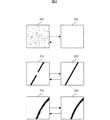
以上をまとめ、本発明では、図2に例示するような情報埋め込みのための改変方法について、改変の目立ちにくさを考慮した優先順位を以下のとおり定める。
(1) 背景部(すなわち、画像の平坦部)のノイズ(すなわち、孤立点)を取り除くように改変する (例えば、図2の画像201を画像202に改変)
(2) 図形の切れ目を塞ぐように改変する (例えば、図2の線分211を線分212に改変)
(3) 図形を所定の方向に沿って(たとえば、輪郭をその方向に沿って)平滑化するように改変する (例えば、図2の輪郭221を輪郭222に改変)
(4) 図形(たとえば、輪郭)を凹凸させるように改変する (例えば、図2の輪郭222を輪郭221に改変)
(5) 図形に切れ目が生じるように改変する (例えば、図2の線分212を線分211に改変)
(6) 背景部(すなわち、画像の平坦部)にノイズ(すなわち、孤立点)が生じるように改変する (例えば、図2の画像202を画像201に改変)。
Summarizing the above, in the present invention, priority is given to the modification method for embedding information as illustrated in FIG. 2 in consideration of the difficulty of modification.
(1) Modify to remove noise (that is, isolated points) in the background (that is, the flat portion of the image) (for example, modify
(2) Modify the figure so as to close the cut (for example, modify
(3) Modify a figure to be smoothed along a predetermined direction (for example, contour along that direction) (for example, modify
(4) Modify a figure (for example, contour) to be uneven (for example, modify
(5) Modify the figure so that there is a cut (for example, modify
(6) The background part (that is, the flat part of the image) is modified so that noise (that is, an isolated point) is generated (for example, the
優先順位が高い改変方法(1),(2)に基づいて透かしを埋め込むことで、透かし挿入後の画質を維持できるようになる。その結果、もし透かし情報量が多く、優先順位が高い改変方法だけでは反転させる画素個数が足りなかった場合には、改変方法(3),(4)も用いて反転画素数を増やせばよい。なお、改変方法(4)-(6)は、画質劣化を招く、できるだけ回避すべき改変方法となる。 By embedding a watermark based on the modification methods (1) and (2) with high priority, the image quality after watermark insertion can be maintained. As a result, if the amount of watermark information is large and the number of pixels to be reversed is insufficient only by the modification method having a high priority, the number of inversion pixels may be increased using the modification methods (3) and (4). The modification methods (4) to (6) are modification methods that cause image quality degradation and should be avoided as much as possible.
視覚特性に基づいて改変の優先順位を設けたことによって、従来技術と比べて透かし埋め込みによる画質劣化が回避でき、さらに埋め込み情報量調整のための自由度も獲得できる。 By providing modification priorities based on visual characteristics, image quality deterioration due to watermark embedding can be avoided as compared with the prior art, and a degree of freedom for adjusting the amount of embedded information can be obtained.
また、本発明は、改変方法(1)-(6)に基づいて改変可能な画素を抽出し、その優先順位を設定する方法として、順位を判定したい画素の周辺3画素×3画素のブロックを取り出し、二値画像の局所的な特徴量である交差数を用いてそのブロックの2値パターンを高速に照合する方法を提供する。 Further, the present invention extracts pixels that can be modified based on the modification methods (1) to (6), and sets a priority order thereof, as a method of setting a block of 3 pixels by 3 pixels around a pixel whose order is to be determined. Provided is a method for quickly collating a binary pattern of a block by using the number of intersections which are taken out and are local feature amounts of the binary image.
以上の透かし情報の埋め込みに対応する透かし情報を検出する方法として、透かしを埋め込む前の原画像を用意しておき、それと比較することで、改変した画素を特定する方法がある。しかし、この方法では、原画を外部に保存しておかなければならないため、透かし技術の運用面から実用的ではない。従って、検出時に原画を必要としない技術が好ましい。 As a method of detecting watermark information corresponding to the above-described watermark information embedding, there is a method of preparing an original image before embedding a watermark and comparing it with the original image to identify a modified pixel. However, this method is not practical from the operational aspect of watermarking technology because the original image must be stored externally. Therefore, a technique that does not require an original image at the time of detection is preferable.
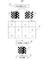
本発明は、透かし検出技術として、原画を用いずに検出を可能とする技術を提供する。そのために、図7に示すように、情報を以下の手順で埋め込む。 The present invention provides a technique that enables detection without using an original image as a watermark detection technique. Therefore, as shown in FIG. 7, information is embedded in the following procedure.
(1) 透かし情報に対応するビット列を2次元ブロック状に配置する(ブロック702参照)。 (1) The bit string corresponding to the watermark information is arranged in a two-dimensional block (see block 702).
(2) 透かしを埋め込む画像と、上記2次元ブロックを上下左右に並べたものとを重ねあわせる。2次元ブロックを並べる際に上下左右一つおきにビット値を反転させた2次元ブロックを用いる。(画像704参照)。 (2) The image in which the watermark is embedded and the one in which the above two-dimensional block is arranged vertically and horizontally are superimposed. When arranging 2D blocks, use 2D blocks with bit values inverted every other side. (See image 704).
(3) 画像中の画素の値と重なるビットの値が異なるとき、画素値を反転する。ただし、ビットの値が異なるすべての画素値を反転するのではなく、改変の優先順位に基づき、改変可能と判定された画素だけを反転する。 (3) Invert the pixel value when the value of the bit that overlaps the value of the pixel in the image is different. However, instead of inverting all pixel values having different bit values, only the pixels determined to be modifiable are inverted based on the modification priority.
こうして埋め込まれた透かし情報は、次の手順で検出できる。 The watermark information embedded in this way can be detected by the following procedure.
(1) 透かしが埋め込まれた画像を透かし情報に対応するブロックの大きさに分割する。 (1) The image in which the watermark is embedded is divided into block sizes corresponding to the watermark information.
(2) 互いに隣り合うブロックの輝度値を正負反転させながら加算し、得られたブロックからビット列を読み取る(ステップ705参照)。 (2) Add the luminance values of blocks adjacent to each other while reversing the polarity, and read a bit string from the obtained block (see step 705).
正負反転させながら加算することで、あらかじめ反転させながら埋め込んだ透かし情報が浮き上がる反面、原画の情報が消失するため、原画像を用いずに埋め込んだ情報を抽出することが可能となる。 By adding while reversing positive and negative, the watermark information embedded while being inverted in advance rises, but since the original image information disappears, it is possible to extract the embedded information without using the original image.
本発明は、人間に改変が知覚されにくいパターンに優先順位を設ける優先順位設定ステップと、このようなパターンを見つけ出し改変可能な画素を抽出する改変画素抽出ステップと、抽出した画素の輝度値を反転させることで情報を埋め込む情報挿入ステップとを備えることを特徴とする、二値画像用電子透かし技術である。計算機上でその機能を持つプログラムを作成し実行すること、あるいは、これと同等な機能を持つハードウェアを作成することによって実現できる。 The present invention provides a priority setting step for setting a priority for a pattern that is difficult to be perceived by humans, a modified pixel extracting step for finding such a pattern and extracting a modifiable pixel, and inverting the luminance value of the extracted pixel. And a digital image watermarking technique for binary images, characterized by comprising an information insertion step of embedding information. This can be realized by creating and executing a program having the function on a computer, or by creating hardware having an equivalent function.
本発明によって、埋め込む情報の量に応じてできるだけ画質を維持するように透かし情報を挿入することが可能になる。 According to the present invention, it becomes possible to insert watermark information so as to maintain the image quality as much as possible according to the amount of information to be embedded.
本発明の実施形態として、(A)で透かし埋め込み装置の概略を述べ、(B)で二値画像の局所的な特徴量である交差数を用いて改変可能画素に優先順位を設定する効率的な技術について説明する。(C)で改変可能画素を抽出する技術の詳細について述べる。(D)で本実施形態の応用例をあげる。 As an embodiment of the present invention, (A) outlines the watermark embedding device, and (B) is an efficient method for setting the priority order to the modifiable pixels using the number of intersections that are local feature amounts of the binary image. A detailed technique will be described. Details of the technique for extracting the modifiable pixels are described in (C). In (D), an application example of this embodiment is given.
(A)透かし埋め込み装置の概略
透かし埋め込み装置101の概略構成を図1に示す。この装置は計算機上のプログラムをプロセッサが実行することもしくは同等の機能を持つハードウェアが動作することによって具現化される。
(A) Outline of Watermark Embedding Apparatus FIG. 1 shows a schematic structure of the
画像データ入力装置111が二値画像データ102を読み込む。同時に、透かし情報入力装置112が、透かし情報103を読み込む。
The image data input device 111 reads the
次に、透かし埋め込み装置101は、二値画像データ102を優先順位設定装置113に送る。この優先順位設定装置113は画像データ102を走査して、画像中各画素の改変の優先順位を設定する。
Next, the
改変画素抽出装置114は、透かし情報103の情報量から改変すべき画素の個数を算出し、優先順位設定装置113にて設定された画素の優先順位を参照することで、画像データ101の中で改変可能となる画素を算出する。
The modified
透かし情報挿入装置115は、改変画素抽出装置114が算出した結果をもとに、改変可能と判定された画素を反転させることで、画像データ102に透かし情報103を挿入する。
The watermark
透かし埋め込み装置101はこのデータを画像データ出力装置116に送り、透かし情報が埋め込まれた画像データを出力する。その結果、透かし入り二値画像データ104が作成される。
The
(B)改変可能画素に優先順位を効率的に設定する方法
図2に示すように、ノイズ散在した画像201のノイズを除去して画像202を得ることや、切断された線分211の切れ目をふさいで連結した線分212に変換することや、輪郭部分が乱れた画像221を、輪郭部分を滑らかにした画像222に平滑化することによって、画質が改善されたと認知されることが、前述のように明らかにされている。また、これらの逆操作は画質劣化を引き起こすことも実証されている。
(B) Method for Efficiently Setting Priorities for Modifyable Pixels As shown in FIG. 2, an
このような視覚特性に基づいて、優先順位を伴う、画素の改変方法(1)〜(6)として具体的に定めた。 Based on such visual characteristics, pixel modification methods (1) to (6) with priority are specifically defined.
このような視覚特性に基づいて改変箇所を見つけ出すためには、例えば、改変を試みる画素の周りの局所的なブロックを取り出し、このブロック内の画素パターンによってブロックの中心にある画素の改変の可否及びその優先順位を判断する技術をとればよい。しかし、画素毎にこのようなパターンとのマッチングを行って改変可否を判断することは、計算量が多く実用的でない。 In order to find the modification location based on such visual characteristics, for example, a local block around a pixel to be modified is extracted, and whether or not the pixel at the center of the block can be modified by the pixel pattern in the block and A technique for determining the priority order may be taken. However, it is not practical to perform the matching with such a pattern for each pixel to determine whether or not modification is possible because of the large amount of calculation.
そこで、本実施例においては改変箇所を効率的に見つける方法として、局所的なブロックを3×3に限定して、二値画像の局所的な特徴量の一つである「交差数」、および3×3ブロック内の輝度値の総和から定量的に改変可否を決定する。なお、交差数に関する文献として次の文献が知られている。 Therefore, in the present embodiment, as a method for efficiently finding the modification portion, the local block is limited to 3 × 3, “the number of intersections” that is one of the local feature amounts of the binary image, and Whether or not alteration is possible is determined quantitatively from the sum of luminance values in the 3 × 3 block. In addition, the following document is known as a document regarding the number of intersections.
横井茂樹、鳥脇純一郎、福村晃夫:「標本化された二値図形のトポロジカルな性質について」、電子通信学会論文誌 D Vol.56-D, No.11, pp.662-669 (1973)。 Shigeki Yokoi, Junichiro Toriwaki, Ikuo Fukumura: "Topological properties of sampled binary figures", IEICE Transactions D Vol.56-D, No.11, pp.662-669 (1973).
定量的に改変可否を決定する判断基準について説明するために、まず用語を定義する。 In order to explain the criteria for quantitatively determining whether or not alteration is possible, terms are first defined.
図3のブロック301のように、3×3ブロックに0から8までラベリングする。中心の0とラベリングされた画素が、改変可能性及び優先順位を算出する画素である。このとき、k=0,...,8について、f(k)を、k番目の画素が黒い場合1、そうでない場合0と定める。同様にg(k)を、k番目の画素が黒い場合0、そうでない場合1とする。
As shown in
以上の定義のもと、交差数Cを、積f(k+1)g(k)のk=1,...,8までの和と定義する。ただしf(9)=f(1)とする。このように定義された交差数Cは、中心画素の周りをk=1からk=8まで反時計回りに一周したときに、画素の輝度値が白から黒に遷移する回数を与える。 Based on the above definition, the number of intersections C is defined as the sum of products f (k + 1) g (k) up to k = 1,. However, f (9) = f (1). The number of intersections C defined in this way gives the number of times that the luminance value of a pixel transitions from white to black when it goes around counterclockwise from k = 1 to k = 8 around the central pixel.
さらに、中心画素のk=0を除くk=1からk=8までのf(k)の和をS、g(k)の和をTと定める。図4に、中心画素が黒い場合の3×3ブロックの具体例401,402をあげる。例えば、ブロック401は輝度値の和Sが3で交差数Cは1である。ブロック402はSが2でCは2である。
Further, the sum of f (k) from k = 1 to k = 8 excluding k = 0 of the central pixel is defined as S, and the sum of g (k) is defined as T. FIG. 4 shows specific examples 401 and 402 of 3 × 3 blocks when the central pixel is black. For example, in the
ここで交差数Cは、ブロック内の画素の分布にだけに依存し、中心画素の輝度値や、ブロック内の黒画素の個数S、白画素の個数Tによらないことに着目する。従って、これらの量も使用することでブロック内に現れた輪郭の形状をさらに絞り込めるはずである。 Note that the number of intersections C depends only on the distribution of pixels in the block, and does not depend on the luminance value of the central pixel, the number S of black pixels in the block, or the number T of white pixels. Therefore, by using these amounts, the shape of the contour appearing in the block should be further narrowed down.
例えば、交差数Cが1の場合、ブロック401のように、Sの値が小さく、かつ中心画素が黒であるとすると、ブロック内には白画素が多いため、黒い注目点が輪郭から突起している可能性が高い。このような画素は高い優先順位で改変可能である。逆に、Sの値が大きい場合には、ブロック内は黒画素が多いため、中心画素が輪郭内に埋没している可能性が高い。この場合、中心画素の改変は輪郭の乱れを招くため改変の優先順位は低くなる。またブロック402はC=2の例であるが、このとき中心の黒画素を白に反転させると、もともとつながっていた線分に切れ目が生じてしまう。従ってこのような改変は低い優先順位となる。
For example, when the number of intersections C is 1, if the value of S is small and the central pixel is black as in the
このように、交差数Cの値と輝度値の和S,Tおよび中心画素の画素値からブロックの形状の種類を限定でき、これらの値から注目点の改変可否およびその優先順位を導出できる。 In this way, the type of block shape can be limited from the sum S and T of the number of intersections C and the luminance value, and the pixel value of the central pixel, and whether or not the attention point can be modified and its priority can be derived from these values.
前述の、課題を解決するための手段で与えた改変条件(1)-(6)と、3×3ブロック全パターン512種類とを照合することで、改変条件(1)-(6)はそれぞれ次に対応することが証明できる。 By comparing the modification conditions (1)-(6) given in the above-mentioned means for solving the problem with 512 types of all 3 × 3 block patterns, the modification conditions (1)-(6) The following can be proved.
(1) C=3,4のとき中心画素を白に反転する
(2) C=0かつS=0のとき中心画素を白に反転する
(3) C=1かつ1≦S≦4のとき中心画素を白に反転する
(4) C=1かつ5≦S≦7のとき中心画素を白に反転する
(5) C=2のとき中心画素を白に反転する
(6) C=0かつS=8のとき中心画素を白に反転する
ただし、これらは中心画素が黒い場合に成立する。中心画素が白い場合は、SをTに変えて、全く同様の式が成立する。また、番号(1)-(6)は優先順位に対応している。番号が大きくなるほど改変の優先順位が低くなり、画質の劣化をひきおこす。
(1) When C = 3,4, the center pixel is inverted to white
(2) Center pixel is inverted to white when C = 0 and S = 0
(3) When C = 1 and 1 ≦ S ≦ 4, the center pixel is inverted to white
(4) Center pixel is inverted to white when C = 1 and 5 ≦ S ≦ 7
(5) Center pixel is inverted to white when C = 2
(6) When C = 0 and S = 8, the center pixel is inverted to white. However, these hold when the center pixel is black. If the center pixel is white, S is changed to T and the same formula is established. Numbers (1)-(6) correspond to priorities. The higher the number, the lower the priority of modification, causing image quality degradation.
この技術に従い、全画像を一画素ずつ走査し、各画素について交差数C、および輝度値の総和S,Tを計算すれば、各画素の改変の可否及びその優先順位を効率的に計算することが可能となる。 According to this technology, if all images are scanned pixel by pixel, and the number of intersections C and the sum of luminance values S and T are calculated for each pixel, the possibility of modification of each pixel and its priority order can be calculated efficiently. Is possible.
(C)改変可能画素を抽出する詳細な方法
改変可能画素を抽出する具体的実施例を2つ、詳細に説明する。これらはいずれも図1の改変画素抽出装置114にて行われる処理であり、計算機上のプログラムをプロセッサが実行することもしくは同等の機能を持つハードウェアが動作することによって具現化される。
(C) Detailed method for extracting modifiable pixels Two specific examples of extracting modifiable pixels will be described in detail. These are all processes performed by the modified
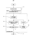
図5を用いて第一の改変可能画素抽出方法を説明する。 The first modifiable pixel extraction method will be described with reference to FIG.
まず優先順位設定装置113が、各画素の優先順位を算出する。これには改変方法(1)〜(6)を直接用いてもよいし、先程述べた、交差数および周辺輝度の総和を用いたより効率的なアルゴリズムを採用してもよい。
First, the priority
次に改変画素抽出装置114は、得られた改変画素の集合を参照して、対応する原画像の輝度を反転させることで透かし情報を挿入する。
Next, the modified
具体的には、ステップ501で改変限界順位Rを1に設定し、ステップ502において、改変画素抽出装置114は、Rよりも高い優先順位、すなわち改変の優先順位(1)の画素だけに改変を施して透かし情報を挿入する。
Specifically, the modification limit rank R is set to 1 in
次に、ステップ503にて、改変画素抽出装置114は、作成した透かし挿入画像が所望の情報量に達したかどうかを判断する。もし所望の情報量に達したと判断した場合、改変画素抽出装置114は、透かし入り画像を出力して終了する。
Next, in
達しなかった場合、改変画素抽出装置114は、ステップ504で変更した輝度値を元に戻し、ステップ505で改変の優先順位を下げるためにRを1増やして、透かし情報挿入ステップ502をやりなおす。所望の情報量に達するまで、改変画素抽出装置114は、ステップ502,503,504,505を繰り返す。
If not, the modified
ただし、もしRが最大値をとった場合、(B)であげた改変方法(6)を用いて透かしを埋め込むことになるが、このとき透かしが非常に目立ちやすくなる。これを回避するために、Rが最大値を取った場合、改変画素抽出装置114は、ステップ502にて、改変方法(6)によって改変可能と判断された画素から、予め設定した所定の反転確率になるようにランダムに選別して透かしを挿入する。ステップ503にて所望の情報量に達していないと判断された場合、この反転確率を上げながらステップ502をやりなおす。
However, if R takes the maximum value, the watermark is embedded using the modification method (6) described in (B). At this time, the watermark becomes very conspicuous. In order to avoid this, when R takes the maximum value, the modified
以上の技術によって、求められる透かしの強度に応じて、画質をできるだけ維持するように、二値画像に透かし情報を挿入できる。 With the above technique, watermark information can be inserted into a binary image so as to maintain the image quality as much as possible according to the required watermark strength.
図6を用いて第二の改変可能画素抽出方法を説明する。これは図5の手順からステップ503,504,505を省略したものである。この処理は改変画素抽出装置114が実行する。
A second modifiable pixel extraction method will be described with reference to FIG. This is obtained by omitting
まず優先順位設定装置113は、各画素の優先順位を算出する。前と同様、改変方法(1)〜(6)を直接用いてもよいし、交差数を用いたより効率的なアルゴリズムを採用してもよい。
First, the priority
次に、ステップ601において、装置のユーザが改変限界順位Rを入力する。例えば、上述の改変方法(1)〜(6)のうち、段階的に適用を認める改変方法のうち、最低順位を改変限界順位R(1≦R≦6)として指定すればよい。
Next, in
ステップ602において、改変画素抽出装置114は、入力されたR以下の優先順位を持つ画素を改変して情報を埋め込む。
In
ステップ601において、例えば画質を優先する場合には、ユーザはRを小さく指定し、できるだけ高い改変の優先順位を用いて改変するようにする。ただし、Rを小さくした結果、透かし情報の埋め込みに失敗する場合がある。また、印刷などの画質が劣化する処理によって、透かし情報が消失する場合もある。このような可能性をできるだけ排除して、透かしの耐性を優先する場合には、ユーザはRを大きくとり、同じ透かし情報を繰り返して大量に埋め込む。
In
なお、このような改変限界順位の入力には、ただ順位を指定するのではなく、ダイアログ611のように、例えば「画質優先」「印刷対応」などといったキーワードを用いるインターフェースを用いても良い。埋め込み情報量や透かしの耐性を調節することが困難だった従来の二値画像用電子透かし技術とは異なり、本実施例によれば、このような強度調整を行うインターフェースをもつ透かし埋め込み装置101を実現できる。
In order to input the modification limit order, an interface using keywords such as “image quality priority” and “printing support” may be used as in the
次に、具体的な情報の埋め込み方法として、検出時に原画を必要としない方法を、図7を用いて説明する。この処理は図1に記載された透かし情報挿入装置115によって実行される。
Next, as a specific information embedding method, a method that does not require an original image at the time of detection will be described with reference to FIG. This process is executed by the watermark
まず透かし情報挿入装置115は、透かし情報に対応するビット列701を、ビット値0,1をそれぞれ黒白として、2次元のブロック702に配置する。ここでブロック702の形状は、ビット列701ができるだけ隙間なく埋まるようにあらかじめ設定しておく。同時に、ブロック702のビット0,1を逆転させたブロック703を構築する。
First, the watermark
次に透かし情報挿入装置115は、画像704に示すようにブロック702と703とが互いに隣り合うように並べて、透かし情報を埋め込む画像にこれらのブロックを重ねあわせる。
Next, the watermark
ここで、埋め込み対象画像中の画素が黒で、かつ重ねたブロック702もしくは703内の対応するビットが白のとき、その黒画素を白に反転させ、画像中の画素が白で、かつ重なるビットが黒のとき、その白画素を黒に反転させることで、情報挿入装置115は透かし情報を埋め込む。ただし、ビットの値に応じてすべての画素値を反転するのではなく、改変の優先順位に基づき、改変対象と判定された画素だけを反転する。
Here, when the pixel in the embedding target image is black and the corresponding bit in the overlapped
このように埋め込まれた透かし情報は、以下の手順により、原画を用いずに正しく検出することができる。検出装置は計算機上のプログラムをプロセッサが実行することもしくは同等の機能を持つハードウェアが動作することによって具現化される。 The watermark information embedded in this way can be correctly detected without using the original image by the following procedure. The detection apparatus is realized by executing a program on a computer by a processor or by operating hardware having an equivalent function.
まず検出装置は、透かしが埋め込まれた画像を、704のように透かし情報に対応するブロック702, 703の大きさに分割する。
First, the detection apparatus divides the image in which the watermark is embedded into
次に検出装置は、ステップ705で互いに隣り合うブロックの輝度値を正負反転させながら加算する。このように、正負反転させながら加算することで、あらかじめ反転させながら埋め込んだ透かし情報が浮き上がる反面、原画の情報が消失するため、原画像を用いずに埋め込んだ情報を抽出することが可能となる。
Next, in
加算の結果ブロック706が得られる。検出装置はブロック706からビット列を読み取ることで、埋め込まれた情報701を原画と比較することなく検出できる。
As a result of the addition, a block 706 is obtained. By detecting the bit string from the block 706, the detection device can detect the embedded
検出装置について図8にまとめる。検出装置801は、透かし検出を試みる二値画像データ802を画像データ入力装置811にて読み込む。画像データ加算装置812は、ステップ705のように、互いに隣り合うブロックの輝度値を正負反転させながら加算する。デコード装置813は、加算して得られたブロック706を透かし情報に変換する。検出装置801は得られた情報を透かし情報検出装置814を経て、透かし情報701を出力する。
The detection device is summarized in FIG. The
(D)応用例
図9をもとに、本実施形態の具体的な応用例をあげる。電子の世界で厳重に管理されている証明書などといった機密性の高い二値画像データも、一度紙に印刷されると簡単に外部に持ち出され、不正流出されてしまうおそれがあったが、本実施例によりそれを抑止することができる。
(D) Application Example A specific application example of the present embodiment will be given based on FIG. Even highly confidential binary image data such as certificates that are strictly managed in the electronic world could be easily taken out once printed on paper, and illegally leaked. It can be suppressed by the embodiment.
本応用例は透かし埋め込み装置101と印刷装置911を備えることを特徴とする。透かし埋め込み装置101は、印刷装置911に接続された、外部の計算機上においてプログラムをプロセッサが実行することにより、あるいは外部のハードウェア装置として、構成される。または、印刷装置911そのものにハードウェアとして内蔵されていてもよい。
This application example includes a
いずれの場合でも、データは埋め込み装置101を経ることでのみ印刷装置911に送信され、直接印刷装置911に送られることはないとする。すなわち、印刷装置911は透かし入り画像のみ受信する装置である。これは計算機上で印刷データを送信するドライバを加工すること、もしくはハード的に耐タンパー処理を施すことで実装できる。
In any case, it is assumed that data is transmitted to the
本応用例は以下の手順による。まず、二値画像データ901を印刷する際、透かし埋め込み装置101に対して、ユーザは透かし情報902を入力する。透かし情報902としてユーザを特定するユーザIDを用いる。ユーザIDを埋め込むことにより、印刷を指示したユーザに関する情報が印刷物そのものに付随する。
This application example is based on the following procedure. First, when printing the
次に透かし埋め込み装置101は、上述の二値電子透かし方法で透かし情報902を二値画像データ901に埋め込み、印刷装置911に送信する。印刷装置911は、透かし情報902が埋め込まれた印刷物903を出力する。
Next, the
なお、透かし埋め込みは、紙に印刷したときに埋め込んだ情報が消失しないように、画質よりも耐性を重視して改変限界順位を低くとり、改変する画素数を多めにとっておくことが望ましい。印刷物は電子データと比べて、簡単に外部に持ち出され、不正流出されてしまうというおそれがあるが、本応用例はこれを抑止することができる。 It should be noted that in watermark embedding, it is desirable to lower the modification limit order with emphasis on durability rather than image quality and to increase the number of pixels to be modified so that information embedded when printed on paper is not lost. Compared with electronic data, printed materials can be easily taken out and illegally leaked, but this application can suppress this.
上記機密データが印刷された印刷物903が外部に不正に流出しているのが発見されたと仮定する。そのとき、発見者または調査者は、まず発見された印刷物904を印刷物読み込み装置912で読み取り、電子データに変換させる。これを図8で説明した透かし検出装置801に入力し、透かし検出装置801は透かし検出を試みる。その結果、あらかじめ透かし埋め込み装置101で埋め込まれていた透かし情報902が検出できる。この透かし情報902にはユーザIDが用いられているので、印刷物904を印刷した人物、すなわち外部への不正流出元が特定できる。
It is assumed that it has been discovered that the printed
以上で述べた実施例によって、印刷された紙の不正流出の犯人特定が可能になるため、不正流出が抑止できると考えられる。 According to the embodiment described above, it is possible to identify the culprit of illegal spillage of printed paper, so that it is considered that spillage can be prevented.
また、この実施例では911として印刷機を例にとったが、複写機を用いた場合も同様である。すなわち、複写する際ユーザID入力を求め、複写物にそのユーザIDを透かし情報902として埋め込んでおけばよい。その結果、複写物の不正流出を抑止することができる。ただし、複写機は、スキャナで読み込んだ原稿を内部で電子データに変換するため、透かし埋め込み装置101は複写機に内蔵しておくべきである。耐タンパー処理を施しておき、透かし埋め込み装置が取り外され、解析されないようにしておくことが望ましい。
Further, in this embodiment, a printing machine is taken as an example as 911, but the same applies when a copying machine is used. That is, when copying, a user ID input is required, and the user ID may be embedded as
さらには、透かし検出装置801に耐タンパー処理を施して複写機に内蔵しておいてもよい。すなわち、複写する前に複写機内部で透かし検出を試みて、もしユーザIDが透かし情報902として埋め込まれているのが発見された場合、これ以上の不正流出を防止するために、複写を停止する。この方法によっても、複写物の不正流出を抑止することができる。
Further, the
この応用例では、上述の通り、透かし強度を調節し、画質よりも耐性を重視して、透かしを埋め込むことが望ましい。 In this application example, as described above, it is desirable to embed a watermark by adjusting the watermark strength and placing more emphasis on durability than image quality.
なお、上記各実施例において、プロセッサによって実行されるプログラムは、それぞれの計算機内の記憶装置に予め格納されていても良いし、必要に応じて、当該計算機が利用可能な、着脱可能な記憶媒体や、通信媒体すなわちネットワークまたはそれを伝搬する搬送波、を介して、他の装置から導入されても良い。 In each of the above embodiments, the program executed by the processor may be stored in advance in a storage device in each computer, or a removable storage medium that can be used by the computer as necessary. Alternatively, it may be introduced from another device through a communication medium, that is, a network or a carrier wave propagating through the network.
101…透かし埋め込み装置、102…入力二値画像データ、103…入力透かし情報、104…出力透かし入り二値画像データ、111…画像データ入力装置、112…透かし情報入力装置、113…優先順位設定装置、114…改変画素抽出装置、115…透かし情報挿入装置、116…画像データ出力装置、201…ノイズを含む画像、202…ノイズがない画像、211…線分に切れ目がある画像、212…線分の切れ目がない画像、221…輪郭が乱れた画像、222…輪郭の乱れがない画像、301…3×3ブロックの番号付けを示す画像、401…中心画素が黒で周辺輝度の総和が3、交差数が1のブロック、402…中心画素が黒で周辺輝度の総和が2、交差数が2のブロック、501…改変優先順位初期化ステップ、502…画素反転ステップ、503…埋め込み情報量を判断するステップ、504…輝度値を元に戻すステップ、505…改変優先順位を加算するステップ、601…改変優先順位入力ステップ、602…画素反転ステップ、611…改変優先順位入力ダイアログ、701…埋め込む透かし情報、702…透かし情報に対応するブロック、703…ブロック702のビット列を逆転したブロック、704…透かし入り画像の模式図、705…正負反転しつつブロックを加算するステップ、706…ステップ705によって得られたブロック、801…透かし検出装置、802…二値画像データ、803…検出された透かし情報、811…画像データ入力装置、812…画像データ加算装置、813…デコード装置、814…透かし情報出力装置、901…機密性の高い二値画像データ、902…ユーザを特定する透かし情報、903…透かし入り画像データが印刷された紙、904…流出した印刷物、911…印刷装置、912…印刷物読み込み装置。
DESCRIPTION OF
Claims (4)
前記二値画像の各画素に,前記挿入する情報とは独立に,当該画素値を改変することの目立ちやすさに応じた改変の優先順位を設定するステップと,
前記二値画像への前記情報の挿入に際して,予め,前記優先順位に対する改変限界順位を,求められる透かし強度に応じて設定するステップと,
挿入する前記情報を構成する各ビット値と,前記二値画像の各画素と,を対応付け,画素値の反転による前記ビット値の挿入が可能で,かつ,設定されている前記優先順位が前記改変限界順位以上の画素を,改変画素として抽出するステップと,
抽出した前記改変画素の画素値を反転させて前記情報を構成するビット値を挿入するステップと,を備える
ことを特徴とする二値画像用電子透かし方法。
By a computer, Ri Do a bit string, the information Ru with a predetermined amount of information, an electronic watermark method for binary image to be inserted into a binary image,
Each pixel of the binary image, independently of the insertion information, and setting a priority modification according to the conspicuousness of altering the pixel values,
Upon insertion of the information of the to binary image, in advance, a step of modifying the limit order for said priority, to set in accordance with the watermark strength required,
Each bit value constituting the information to be inserted is associated with each pixel of the binary image, the bit value can be inserted by reversing the pixel value , and the set priority order is the modified limit order or more pixels, and extracting as modified pixel,
Extracted step and, watermarking method for binary image, characterized in that it comprises a a pixel value is reversed to insert a bit value constituting the information of said modified pixels.
前記改変画素を抽出するステップでは,一つの前記ビット値と前記二値画像の複数の画素とを対応付け,
前記ビット値を挿入するステップでは,一つの前記ビット値に対応する前記複数の画素のうち,設定した前記優先順位が前記改変限界順位以上の前記改変画素の画素値を反転させる
ことを特徴とする二値画像用電子透かし方法。 The electronic watermarking method for binary images according to claim 1,
In the step of extracting the modified pixel , one bit value is associated with a plurality of pixels of the binary image,
In the step of inserting the bit value, among the plurality of pixels corresponding to one of the bit values, characterized in that said priority is set to invert the pixel value of said modified pixels above said modified limits Position Digital watermarking method for binary images.
予め定めた前記改変限界順位に基づいて前記ビット値を挿入し,挿入された情報量が不足する場合には,該改変限界順位を下げるステップと,
前記ビット値を挿入した画素の画素値を挿入前に戻すステップと,
前記下げた改変限界順位に基づいて,前記抽出するステップと前記挿入するステップとを行うステップと,を有する
ことを特徴とする二値画像用電子透かし方法。 The electronic watermarking method for binary images according to claim 2, further comprising:
Predetermined inserting the modified limit the bit value based on the ranking, when inserted information amount is insufficient, the steps of lowering the said alteration limit order,
And returning before inserting the pixel value of the pixel of inserting the pre-Symbol bit value,
Based on the modification limit rank lowered the electronic watermark method for binary image characterized by having the steps of: performing the steps of the insertion step of the extraction.
前記ビット値を挿入するステップは,
前記ビット列を2次元ブロック状に配置するステップと,
前記2次元ブロックと,前記2次元ブロックのビット値を反転させたブロックとを上下左右交互に並べて,前記二値画像と対応づけるステップと,
前記改変画素を抽出するステップにおいて抽出した画素の画素値を,対応する前記2次元ブロックのビット値に応じて,反転するステップと,を備える
ことを特徴とする二値画像用電子透かし方法。 The electronic watermarking method for binary images according to claim 1,
Inserting the bit value comprises:
Arranging the bit string in a two-dimensional block;
Arranging the two-dimensional block and a block obtained by inverting the bit value of the two-dimensional block alternately up and down, left and right, and associating with the binary image;
And a step of inverting the pixel value of the pixel extracted in the step of extracting the modified pixel in accordance with the bit value of the corresponding two-dimensional block.
Priority Applications (2)
| Application Number | Priority Date | Filing Date | Title |
|---|---|---|---|
| JP2003343917A JP4193665B2 (en) | 2003-03-05 | 2003-10-02 | Digital watermarking method for binary images |
| US10/841,842 US7499565B2 (en) | 2003-03-05 | 2004-05-10 | Method of watermarking for binary images |
Applications Claiming Priority (2)
| Application Number | Priority Date | Filing Date | Title |
|---|---|---|---|
| JP2003057930 | 2003-03-05 | ||
| JP2003343917A JP4193665B2 (en) | 2003-03-05 | 2003-10-02 | Digital watermarking method for binary images |
Related Child Applications (1)
| Application Number | Title | Priority Date | Filing Date |
|---|---|---|---|
| JP2007023650A Division JP4389942B2 (en) | 2003-03-05 | 2007-02-02 | Digital watermarking method for binary images |
Publications (3)
| Publication Number | Publication Date |
|---|---|
| JP2004289783A JP2004289783A (en) | 2004-10-14 |
| JP2004289783A5 JP2004289783A5 (en) | 2006-05-11 |
| JP4193665B2 true JP4193665B2 (en) | 2008-12-10 |
Family
ID=33302068
Family Applications (1)
| Application Number | Title | Priority Date | Filing Date |
|---|---|---|---|
| JP2003343917A Expired - Fee Related JP4193665B2 (en) | 2003-03-05 | 2003-10-02 | Digital watermarking method for binary images |
Country Status (2)
| Country | Link |
|---|---|
| US (1) | US7499565B2 (en) |
| JP (1) | JP4193665B2 (en) |
Cited By (1)
| Publication number | Priority date | Publication date | Assignee | Title |
|---|---|---|---|---|
| JP7410817B2 (en) | 2020-07-27 | 2024-01-10 | 株式会社小糸製作所 | System and method for prompting people to get on and off a moving object |
Families Citing this family (30)
| Publication number | Priority date | Publication date | Assignee | Title |
|---|---|---|---|---|
| US7193751B2 (en) * | 2002-12-12 | 2007-03-20 | Xerox Corporation | Tag control for runtime glossmarks |
| US7352493B2 (en) * | 2003-12-12 | 2008-04-01 | Xerox Corporation | Enhancement of glossmark images at low and high densities |
| US7382495B2 (en) * | 2003-12-12 | 2008-06-03 | Xerox Corporation | Reduction of differential gloss |
| US7324662B2 (en) * | 2004-05-21 | 2008-01-29 | Nanyang Technological University | Method, software, and device for hiding data in binary image, while preserving image quality |
| US7301675B2 (en) * | 2004-06-29 | 2007-11-27 | Xerox Corporation | Glossmark images with clear toner |
| JP2006065524A (en) | 2004-08-26 | 2006-03-09 | Hitachi Ltd | Document processing apparatus and method |
| US7304770B2 (en) * | 2004-08-30 | 2007-12-04 | Xerox Corporation | Reduction of differential gloss with halftoned clear toner |
| US7391537B2 (en) * | 2004-09-28 | 2008-06-24 | Xerox Corporation | User interface for differential gloss images |
| US7324241B2 (en) * | 2004-09-29 | 2008-01-29 | Xerox Corporation | Variable data differential gloss images |
| JP4591234B2 (en) * | 2005-06-29 | 2010-12-01 | 株式会社日立製作所 | Watermark information embedding device, watermark information embedding method, and print management system |
| AU2005209707B2 (en) * | 2005-09-13 | 2008-08-14 | Canon Kabushiki Kaisha | Adaptive mark placement |
| US7583813B2 (en) | 2005-09-28 | 2009-09-01 | Kabushiki Kaisha Toshiba | Embedding data reproduce apparatus |
| US7688993B2 (en) * | 2005-10-21 | 2010-03-30 | Nanyang Technological University | Software and method for embedding data in two color images |
| JP4510092B2 (en) | 2005-10-25 | 2010-07-21 | 富士通株式会社 | Digital watermark embedding and detection |
| JP2007180710A (en) | 2005-12-27 | 2007-07-12 | Oki Data Corp | Data processing method, data processing device and data processing system |
| US8090141B2 (en) | 2006-01-31 | 2012-01-03 | Xerox Corporation | System and method to automatically establish preferred area for image-wise watermark |
| US8665967B2 (en) * | 2006-02-15 | 2014-03-04 | Samsung Electronics Co., Ltd. | Method and system for bit reorganization and packetization of uncompressed video for transmission over wireless communication channels |
| JP4595014B2 (en) | 2006-09-19 | 2010-12-08 | 富士通株式会社 | Digital watermark embedding device and detection device |
| JP5015540B2 (en) | 2006-09-28 | 2012-08-29 | 富士通株式会社 | Digital watermark embedding device and detection device |
| US9277091B2 (en) * | 2007-05-22 | 2016-03-01 | Xerox Corporation | Embedding information in paper forms |
| JP4837101B2 (en) | 2007-08-31 | 2011-12-14 | 富士通株式会社 | Digital watermark embedding device, digital watermark detection device, and program |
| TWI412298B (en) * | 2008-09-18 | 2013-10-11 | Richtek Technology Corp | Led bulb, light emitting device control method, and light emitting device controller circuit with dimming function adjustable by ac signal |
| KR101529082B1 (en) * | 2008-12-01 | 2015-06-17 | 주식회사 케이티 | Apparatus for watermarking by dividing off tracking information and method therefor |
| JP5176940B2 (en) * | 2008-12-24 | 2013-04-03 | 富士ゼロックス株式会社 | Image processing apparatus and program |
| JP5031793B2 (en) * | 2009-05-15 | 2012-09-26 | 株式会社日立製作所 | Tamper detection system, watermark information embedding device, tamper detection device, watermark information embedding method, and tamper detection method |
| WO2011133328A2 (en) * | 2010-04-19 | 2011-10-27 | Robert Valentine | A casino chess game |
| CN101976428B (en) * | 2010-07-30 | 2012-04-04 | 南开大学 | Binary image fragile watermark embedding and extraction method based on topology structure |
| EP2747406A1 (en) * | 2012-12-21 | 2014-06-25 | Gemalto SA | Method for embedding auxiliary data in an image, method for reading embedded auxiliary data in an image, and medium personalized by selective exposure to photons |
| KR101877372B1 (en) * | 2017-05-19 | 2018-07-13 | 주식회사 하루컴퍼니 | Method for embedding and extraction of watermarking data |
| CN115811578B (en) * | 2023-02-03 | 2023-05-02 | 潍坊医学院附属医院 | Digital processing method for medical recuperation |
Family Cites Families (9)
| Publication number | Priority date | Publication date | Assignee | Title |
|---|---|---|---|---|
| JP2827458B2 (en) * | 1990-06-15 | 1998-11-25 | 株式会社日立製作所 | Inference processing method |
| US7720249B2 (en) * | 1993-11-18 | 2010-05-18 | Digimarc Corporation | Watermark embedder and reader |
| US6112234A (en) * | 1997-07-01 | 2000-08-29 | Leiper; Thomas W. | Method for transfer of radiographic images |
| JP3397157B2 (en) * | 1999-01-13 | 2003-04-14 | 日本電気株式会社 | Digital watermark insertion system |
| JP2001061052A (en) * | 1999-08-20 | 2001-03-06 | Nec Corp | Method for inserting electronic watermark data, its device and electronic watermark data detector |
| JP3780175B2 (en) | 2000-05-31 | 2006-05-31 | キヤノン株式会社 | Image processing apparatus, image processing method, and storage medium |
| JP2002232698A (en) | 2000-11-30 | 2002-08-16 | Kowa Co | Method and device for embedding and extracting electronic watermark |
| JP3732094B2 (en) | 2001-01-12 | 2006-01-05 | コニカミノルタビジネステクノロジーズ株式会社 | Image processing apparatus and image processing method |
| JP3614784B2 (en) | 2001-02-01 | 2005-01-26 | 松下電器産業株式会社 | Information embedding device, information embedding method, information extracting device, and information extracting method |
-
2003
- 2003-10-02 JP JP2003343917A patent/JP4193665B2/en not_active Expired - Fee Related
-
2004
- 2004-05-10 US US10/841,842 patent/US7499565B2/en not_active Expired - Fee Related
Cited By (1)
| Publication number | Priority date | Publication date | Assignee | Title |
|---|---|---|---|---|
| JP7410817B2 (en) | 2020-07-27 | 2024-01-10 | 株式会社小糸製作所 | System and method for prompting people to get on and off a moving object |
Also Published As
| Publication number | Publication date |
|---|---|
| US7499565B2 (en) | 2009-03-03 |
| US20050025333A1 (en) | 2005-02-03 |
| JP2004289783A (en) | 2004-10-14 |
Similar Documents
| Publication | Publication Date | Title |
|---|---|---|
| JP4193665B2 (en) | Digital watermarking method for binary images | |
| US6556688B1 (en) | Watermarking with random zero-mean patches for printer tracking | |
| Chen et al. | High payload steganography mechanism using hybrid edge detector | |
| JP5015540B2 (en) | Digital watermark embedding device and detection device | |
| US20050018845A1 (en) | Electronic watermark embedding device, electronic watermark detection device, electronic watermark embedding method, and electronic watermark detection method | |
| US8077907B2 (en) | System and method for the generation of correlation-based digital watermarks | |
| JP2005328528A (en) | Processing method and system for secret mark of digital image | |
| JP2009232129A (en) | Image processing apparatus, image processing method, and image processing program | |
| Ni et al. | Secure semi-blind watermarking based on iteration mapping and image features | |
| JP4837101B2 (en) | Digital watermark embedding device, digital watermark detection device, and program | |
| JP4595014B2 (en) | Digital watermark embedding device and detection device | |
| Chen et al. | Recent developments in document image watermarking and data hiding | |
| JP4061143B2 (en) | Image processing apparatus and image processing method | |
| JP4389942B2 (en) | Digital watermarking method for binary images | |
| JPWO2007049333A1 (en) | Background pattern image generation method | |
| JP2005057780A (en) | Insertion of watermark into image derived from source image and detection of it | |
| JP4469301B2 (en) | Information embedding device, printing medium, and information reading device | |
| JP4310031B2 (en) | Image processing apparatus, image processing method, and storage medium | |
| JP2007097189A (en) | Information embedding apparatus, image forming apparatus, and information embedding method | |
| Chen et al. | Data hiding in document images | |
| CN113393363A (en) | Watermark embedding method, watermark extracting method, storage medium and electronic equipment | |
| JP2006295857A (en) | Ground tint processing method and image forming apparatus | |
| JP3787511B2 (en) | Image processing apparatus and image processing method | |
| JP6920719B2 (en) | Digital watermarking device and method | |
| JP2001119562A (en) | Image processor, image processing method and storage medium |
Legal Events
| Date | Code | Title | Description |
|---|---|---|---|
| A521 | Written amendment |
Free format text: JAPANESE INTERMEDIATE CODE: A523 Effective date: 20060315 |
|
| A621 | Written request for application examination |
Free format text: JAPANESE INTERMEDIATE CODE: A621 Effective date: 20060315 |
|
| RD01 | Notification of change of attorney |
Free format text: JAPANESE INTERMEDIATE CODE: A7421 Effective date: 20060421 |
|
| A977 | Report on retrieval |
Free format text: JAPANESE INTERMEDIATE CODE: A971007 Effective date: 20070920 |
|
| A131 | Notification of reasons for refusal |
Free format text: JAPANESE INTERMEDIATE CODE: A131 Effective date: 20070925 |
|
| A521 | Written amendment |
Free format text: JAPANESE INTERMEDIATE CODE: A523 Effective date: 20071121 |
|
| A02 | Decision of refusal |
Free format text: JAPANESE INTERMEDIATE CODE: A02 Effective date: 20080527 |
|
| A521 | Written amendment |
Free format text: JAPANESE INTERMEDIATE CODE: A523 Effective date: 20080725 |
|
| A911 | Transfer to examiner for re-examination before appeal (zenchi) |
Free format text: JAPANESE INTERMEDIATE CODE: A911 Effective date: 20080804 |
|
| TRDD | Decision of grant or rejection written | ||
| A01 | Written decision to grant a patent or to grant a registration (utility model) |
Free format text: JAPANESE INTERMEDIATE CODE: A01 Effective date: 20080902 |
|
| A01 | Written decision to grant a patent or to grant a registration (utility model) |
Free format text: JAPANESE INTERMEDIATE CODE: A01 |
|
| A61 | First payment of annual fees (during grant procedure) |
Free format text: JAPANESE INTERMEDIATE CODE: A61 Effective date: 20080915 |
|
| FPAY | Renewal fee payment (event date is renewal date of database) |
Free format text: PAYMENT UNTIL: 20111003 Year of fee payment: 3 |
|
| FPAY | Renewal fee payment (event date is renewal date of database) |
Free format text: PAYMENT UNTIL: 20121003 Year of fee payment: 4 |
|
| FPAY | Renewal fee payment (event date is renewal date of database) |
Free format text: PAYMENT UNTIL: 20131003 Year of fee payment: 5 |
|
| LAPS | Cancellation because of no payment of annual fees |