JP4172120B2 - COMMUNICATION DEVICE AND COMMUNICATION METHOD, COMMUNICATION TERMINAL DEVICE - Google Patents
COMMUNICATION DEVICE AND COMMUNICATION METHOD, COMMUNICATION TERMINAL DEVICE Download PDFInfo
- Publication number
- JP4172120B2 JP4172120B2 JP32344699A JP32344699A JP4172120B2 JP 4172120 B2 JP4172120 B2 JP 4172120B2 JP 32344699 A JP32344699 A JP 32344699A JP 32344699 A JP32344699 A JP 32344699A JP 4172120 B2 JP4172120 B2 JP 4172120B2
- Authority
- JP
- Japan
- Prior art keywords
- host device
- communication network
- protocol
- communication
- wireless communication
- Prior art date
- Legal status (The legal status is an assumption and is not a legal conclusion. Google has not performed a legal analysis and makes no representation as to the accuracy of the status listed.)
- Expired - Fee Related
Links
- 238000004891 communication Methods 0.000 title claims description 721
- 238000000034 method Methods 0.000 title claims description 78
- 238000003860 storage Methods 0.000 claims description 60
- 230000005540 biological transmission Effects 0.000 claims description 46
- 230000004044 response Effects 0.000 claims description 26
- 230000015654 memory Effects 0.000 description 94
- 238000012545 processing Methods 0.000 description 76
- 230000006386 memory function Effects 0.000 description 33
- 239000000758 substrate Substances 0.000 description 31
- 230000008569 process Effects 0.000 description 28
- 230000006870 function Effects 0.000 description 22
- 238000010586 diagram Methods 0.000 description 20
- 230000001413 cellular effect Effects 0.000 description 10
- 238000006243 chemical reaction Methods 0.000 description 9
- 238000010295 mobile communication Methods 0.000 description 9
- 238000012546 transfer Methods 0.000 description 7
- 238000007726 management method Methods 0.000 description 5
- 230000007704 transition Effects 0.000 description 4
- 239000006096 absorbing agent Substances 0.000 description 3
- 238000005516 engineering process Methods 0.000 description 3
- 229910000679 solder Inorganic materials 0.000 description 3
- 238000001228 spectrum Methods 0.000 description 3
- 230000001360 synchronised effect Effects 0.000 description 3
- 238000007796 conventional method Methods 0.000 description 2
- 238000013461 design Methods 0.000 description 2
- 230000000694 effects Effects 0.000 description 2
- 238000003384 imaging method Methods 0.000 description 2
- 239000002184 metal Substances 0.000 description 2
- 230000006855 networking Effects 0.000 description 2
- 239000004065 semiconductor Substances 0.000 description 2
- 230000007480 spreading Effects 0.000 description 2
- 238000003892 spreading Methods 0.000 description 2
- 230000002159 abnormal effect Effects 0.000 description 1
- 230000003213 activating effect Effects 0.000 description 1
- 230000003044 adaptive effect Effects 0.000 description 1
- 230000002457 bidirectional effect Effects 0.000 description 1
- 239000003990 capacitor Substances 0.000 description 1
- 230000008859 change Effects 0.000 description 1
- 238000012790 confirmation Methods 0.000 description 1
- 238000012937 correction Methods 0.000 description 1
- 125000004122 cyclic group Chemical group 0.000 description 1
- 238000001514 detection method Methods 0.000 description 1
- 238000011161 development Methods 0.000 description 1
- 238000009792 diffusion process Methods 0.000 description 1
- 238000009826 distribution Methods 0.000 description 1
- 238000012905 input function Methods 0.000 description 1
- 238000004519 manufacturing process Methods 0.000 description 1
- 239000000463 material Substances 0.000 description 1
- 230000007246 mechanism Effects 0.000 description 1
- 230000008520 organization Effects 0.000 description 1
- 229920001690 polydopamine Polymers 0.000 description 1
- 239000007787 solid Substances 0.000 description 1
Images


Classifications
-
- H—ELECTRICITY
- H04—ELECTRIC COMMUNICATION TECHNIQUE
- H04W—WIRELESS COMMUNICATION NETWORKS
- H04W88/00—Devices specially adapted for wireless communication networks, e.g. terminals, base stations or access point devices
- H04W88/02—Terminal devices
- H04W88/06—Terminal devices adapted for operation in multiple networks or having at least two operational modes, e.g. multi-mode terminals
-
- H—ELECTRICITY
- H01—ELECTRIC ELEMENTS
- H01Q—ANTENNAS, i.e. RADIO AERIALS
- H01Q1/00—Details of, or arrangements associated with, antennas
- H01Q1/12—Supports; Mounting means
- H01Q1/22—Supports; Mounting means by structural association with other equipment or articles
- H01Q1/2283—Supports; Mounting means by structural association with other equipment or articles mounted in or on the surface of a semiconductor substrate as a chip-type antenna or integrated with other components into an IC package
-
- H—ELECTRICITY
- H04—ELECTRIC COMMUNICATION TECHNIQUE
- H04B—TRANSMISSION
- H04B1/00—Details of transmission systems, not covered by a single one of groups H04B3/00 - H04B13/00; Details of transmission systems not characterised by the medium used for transmission
- H04B1/38—Transceivers, i.e. devices in which transmitter and receiver form a structural unit and in which at least one part is used for functions of transmitting and receiving
- H04B1/3816—Mechanical arrangements for accommodating identification devices, e.g. cards or chips; with connectors for programming identification devices
-
- H04B5/72—
-
- H—ELECTRICITY
- H04—ELECTRIC COMMUNICATION TECHNIQUE
- H04L—TRANSMISSION OF DIGITAL INFORMATION, e.g. TELEGRAPHIC COMMUNICATION
- H04L12/00—Data switching networks
- H04L12/28—Data switching networks characterised by path configuration, e.g. LAN [Local Area Networks] or WAN [Wide Area Networks]
-
- H—ELECTRICITY
- H04—ELECTRIC COMMUNICATION TECHNIQUE
- H04L—TRANSMISSION OF DIGITAL INFORMATION, e.g. TELEGRAPHIC COMMUNICATION
- H04L12/00—Data switching networks
- H04L12/54—Store-and-forward switching systems
- H04L12/56—Packet switching systems
- H04L12/5601—Transfer mode dependent, e.g. ATM
- H04L12/5602—Bandwidth control in ATM Networks, e.g. leaky bucket
-
- H—ELECTRICITY
- H04—ELECTRIC COMMUNICATION TECHNIQUE
- H04W—WIRELESS COMMUNICATION NETWORKS
- H04W12/00—Security arrangements; Authentication; Protecting privacy or anonymity
- H04W12/06—Authentication
-
- H—ELECTRICITY
- H04—ELECTRIC COMMUNICATION TECHNIQUE
- H04W—WIRELESS COMMUNICATION NETWORKS
- H04W28/00—Network traffic management; Network resource management
- H04W28/16—Central resource management; Negotiation of resources or communication parameters, e.g. negotiating bandwidth or QoS [Quality of Service]
- H04W28/18—Negotiating wireless communication parameters
-
- H—ELECTRICITY
- H05—ELECTRIC TECHNIQUES NOT OTHERWISE PROVIDED FOR
- H05K—PRINTED CIRCUITS; CASINGS OR CONSTRUCTIONAL DETAILS OF ELECTRIC APPARATUS; MANUFACTURE OF ASSEMBLAGES OF ELECTRICAL COMPONENTS
- H05K5/00—Casings, cabinets or drawers for electric apparatus
- H05K5/02—Details
- H05K5/0247—Electrical details of casings, e.g. terminals, passages for cables or wiring
-
- H—ELECTRICITY
- H01—ELECTRIC ELEMENTS
- H01L—SEMICONDUCTOR DEVICES NOT COVERED BY CLASS H10
- H01L2224/00—Indexing scheme for arrangements for connecting or disconnecting semiconductor or solid-state bodies and methods related thereto as covered by H01L24/00
- H01L2224/01—Means for bonding being attached to, or being formed on, the surface to be connected, e.g. chip-to-package, die-attach, "first-level" interconnects; Manufacturing methods related thereto
- H01L2224/10—Bump connectors; Manufacturing methods related thereto
- H01L2224/15—Structure, shape, material or disposition of the bump connectors after the connecting process
- H01L2224/16—Structure, shape, material or disposition of the bump connectors after the connecting process of an individual bump connector
- H01L2224/161—Disposition
- H01L2224/16135—Disposition the bump connector connecting between different semiconductor or solid-state bodies, i.e. chip-to-chip
- H01L2224/16145—Disposition the bump connector connecting between different semiconductor or solid-state bodies, i.e. chip-to-chip the bodies being stacked
-
- H—ELECTRICITY
- H01—ELECTRIC ELEMENTS
- H01L—SEMICONDUCTOR DEVICES NOT COVERED BY CLASS H10
- H01L2224/00—Indexing scheme for arrangements for connecting or disconnecting semiconductor or solid-state bodies and methods related thereto as covered by H01L24/00
- H01L2224/01—Means for bonding being attached to, or being formed on, the surface to be connected, e.g. chip-to-package, die-attach, "first-level" interconnects; Manufacturing methods related thereto
- H01L2224/10—Bump connectors; Manufacturing methods related thereto
- H01L2224/15—Structure, shape, material or disposition of the bump connectors after the connecting process
- H01L2224/16—Structure, shape, material or disposition of the bump connectors after the connecting process of an individual bump connector
- H01L2224/161—Disposition
- H01L2224/16151—Disposition the bump connector connecting between a semiconductor or solid-state body and an item not being a semiconductor or solid-state body, e.g. chip-to-substrate, chip-to-passive
- H01L2224/16221—Disposition the bump connector connecting between a semiconductor or solid-state body and an item not being a semiconductor or solid-state body, e.g. chip-to-substrate, chip-to-passive the body and the item being stacked
- H01L2224/16225—Disposition the bump connector connecting between a semiconductor or solid-state body and an item not being a semiconductor or solid-state body, e.g. chip-to-substrate, chip-to-passive the body and the item being stacked the item being non-metallic, e.g. insulating substrate with or without metallisation
-
- H—ELECTRICITY
- H01—ELECTRIC ELEMENTS
- H01L—SEMICONDUCTOR DEVICES NOT COVERED BY CLASS H10
- H01L2224/00—Indexing scheme for arrangements for connecting or disconnecting semiconductor or solid-state bodies and methods related thereto as covered by H01L24/00
- H01L2224/01—Means for bonding being attached to, or being formed on, the surface to be connected, e.g. chip-to-package, die-attach, "first-level" interconnects; Manufacturing methods related thereto
- H01L2224/42—Wire connectors; Manufacturing methods related thereto
- H01L2224/44—Structure, shape, material or disposition of the wire connectors prior to the connecting process
- H01L2224/45—Structure, shape, material or disposition of the wire connectors prior to the connecting process of an individual wire connector
- H01L2224/45001—Core members of the connector
- H01L2224/45099—Material
- H01L2224/451—Material with a principal constituent of the material being a metal or a metalloid, e.g. boron (B), silicon (Si), germanium (Ge), arsenic (As), antimony (Sb), tellurium (Te) and polonium (Po), and alloys thereof
- H01L2224/45138—Material with a principal constituent of the material being a metal or a metalloid, e.g. boron (B), silicon (Si), germanium (Ge), arsenic (As), antimony (Sb), tellurium (Te) and polonium (Po), and alloys thereof the principal constituent melting at a temperature of greater than or equal to 950°C and less than 1550°C
- H01L2224/45144—Gold (Au) as principal constituent
-
- H—ELECTRICITY
- H01—ELECTRIC ELEMENTS
- H01L—SEMICONDUCTOR DEVICES NOT COVERED BY CLASS H10
- H01L2224/00—Indexing scheme for arrangements for connecting or disconnecting semiconductor or solid-state bodies and methods related thereto as covered by H01L24/00
- H01L2224/01—Means for bonding being attached to, or being formed on, the surface to be connected, e.g. chip-to-package, die-attach, "first-level" interconnects; Manufacturing methods related thereto
- H01L2224/42—Wire connectors; Manufacturing methods related thereto
- H01L2224/47—Structure, shape, material or disposition of the wire connectors after the connecting process
- H01L2224/48—Structure, shape, material or disposition of the wire connectors after the connecting process of an individual wire connector
- H01L2224/4805—Shape
- H01L2224/4809—Loop shape
- H01L2224/48091—Arched
-
- H—ELECTRICITY
- H01—ELECTRIC ELEMENTS
- H01L—SEMICONDUCTOR DEVICES NOT COVERED BY CLASS H10
- H01L2224/00—Indexing scheme for arrangements for connecting or disconnecting semiconductor or solid-state bodies and methods related thereto as covered by H01L24/00
- H01L2224/01—Means for bonding being attached to, or being formed on, the surface to be connected, e.g. chip-to-package, die-attach, "first-level" interconnects; Manufacturing methods related thereto
- H01L2224/42—Wire connectors; Manufacturing methods related thereto
- H01L2224/47—Structure, shape, material or disposition of the wire connectors after the connecting process
- H01L2224/48—Structure, shape, material or disposition of the wire connectors after the connecting process of an individual wire connector
- H01L2224/484—Connecting portions
- H01L2224/48463—Connecting portions the connecting portion on the bonding area of the semiconductor or solid-state body being a ball bond
- H01L2224/48465—Connecting portions the connecting portion on the bonding area of the semiconductor or solid-state body being a ball bond the other connecting portion not on the bonding area being a wedge bond, i.e. ball-to-wedge, regular stitch
-
- H—ELECTRICITY
- H01—ELECTRIC ELEMENTS
- H01L—SEMICONDUCTOR DEVICES NOT COVERED BY CLASS H10
- H01L2924/00—Indexing scheme for arrangements or methods for connecting or disconnecting semiconductor or solid-state bodies as covered by H01L24/00
- H01L2924/15—Details of package parts other than the semiconductor or other solid state devices to be connected
- H01L2924/151—Die mounting substrate
- H01L2924/153—Connection portion
- H01L2924/1531—Connection portion the connection portion being formed only on the surface of the substrate opposite to the die mounting surface
- H01L2924/15311—Connection portion the connection portion being formed only on the surface of the substrate opposite to the die mounting surface being a ball array, e.g. BGA
-
- H—ELECTRICITY
- H01—ELECTRIC ELEMENTS
- H01L—SEMICONDUCTOR DEVICES NOT COVERED BY CLASS H10
- H01L2924/00—Indexing scheme for arrangements or methods for connecting or disconnecting semiconductor or solid-state bodies as covered by H01L24/00
- H01L2924/15—Details of package parts other than the semiconductor or other solid state devices to be connected
- H01L2924/151—Die mounting substrate
- H01L2924/153—Connection portion
- H01L2924/1532—Connection portion the connection portion being formed on the die mounting surface of the substrate
- H01L2924/1533—Connection portion the connection portion being formed on the die mounting surface of the substrate the connection portion being formed both on the die mounting surface of the substrate and outside the die mounting surface of the substrate
- H01L2924/15331—Connection portion the connection portion being formed on the die mounting surface of the substrate the connection portion being formed both on the die mounting surface of the substrate and outside the die mounting surface of the substrate being a ball array, e.g. BGA
-
- H—ELECTRICITY
- H01—ELECTRIC ELEMENTS
- H01L—SEMICONDUCTOR DEVICES NOT COVERED BY CLASS H10
- H01L2924/00—Indexing scheme for arrangements or methods for connecting or disconnecting semiconductor or solid-state bodies as covered by H01L24/00
- H01L2924/15—Details of package parts other than the semiconductor or other solid state devices to be connected
- H01L2924/181—Encapsulation
-
- H—ELECTRICITY
- H04—ELECTRIC COMMUNICATION TECHNIQUE
- H04L—TRANSMISSION OF DIGITAL INFORMATION, e.g. TELEGRAPHIC COMMUNICATION
- H04L12/00—Data switching networks
- H04L12/54—Store-and-forward switching systems
- H04L12/56—Packet switching systems
- H04L12/5601—Transfer mode dependent, e.g. ATM
- H04L2012/5619—Network Node Interface, e.g. tandem connections, transit switching
- H04L2012/562—Routing
-
- H—ELECTRICITY
- H04—ELECTRIC COMMUNICATION TECHNIQUE
- H04L—TRANSMISSION OF DIGITAL INFORMATION, e.g. TELEGRAPHIC COMMUNICATION
- H04L12/00—Data switching networks
- H04L12/54—Store-and-forward switching systems
- H04L12/56—Packet switching systems
- H04L12/5601—Transfer mode dependent, e.g. ATM
- H04L2012/5638—Services, e.g. multimedia, GOS, QOS
- H04L2012/5665—Interaction of ATM with other protocols
-
- H—ELECTRICITY
- H04—ELECTRIC COMMUNICATION TECHNIQUE
- H04M—TELEPHONIC COMMUNICATION
- H04M1/00—Substation equipment, e.g. for use by subscribers
- H04M1/253—Telephone sets using digital voice transmission
- H04M1/2535—Telephone sets using digital voice transmission adapted for voice communication over an Internet Protocol [IP] network
-
- H—ELECTRICITY
- H04—ELECTRIC COMMUNICATION TECHNIQUE
- H04M—TELEPHONIC COMMUNICATION
- H04M2250/00—Details of telephonic subscriber devices
- H04M2250/02—Details of telephonic subscriber devices including a Bluetooth interface
Description
【0001】
【発明の属する技術分野】
本発明は、例えばBluetooth方式を採用した無線LAN(Local Area Network)システムに用いて好適な通信装置及び通信方法、通信端末装置に関する。
【0002】
【従来の技術】
近年、無線LAN(Local Area Network)システムの分野において、2.4GHz帯の電波を用い、周波数ホッピング方式に準じた処理をして各機器間でデータの送受信を行うBluetooth方式を採用したシステムの開発が行われている。
【0003】
上記Bluetooth方式は、無線通信テクノロジを用い、コンピュータ、電気通信、ネットワーキング等の各業界の企業が共同で開発を進めており、複数のパーソナルコンピュータやデバイス間でアドホックな無線(RF)ネットワーキングを実現するための方式である。このBluetooth方式は、インテル、エリクソン、IBM、ノキア、東芝(登録商標)といった企業がBluetooth SIG(Special Interest Group)に参加して策定された。このBluetooth方式により、ノートブック、PDA(Personal Digital Assistant)、或いは携帯電話が、情報や各種サービスを無線通信でパーソナルコンピュータと共有することができ、面倒なケーブル接続を不要とする。このようなBluetooth方式は、“Bluetooth(TM)Special Interest Group、Bluetooth仕様書バージョン1.0”で開示されている。
【0004】
Bluetooth方式ではアドホックな近短距離接続向けに設計されているため、通信可能な範囲は標準で10m以内とされている。このBluetooth方式では、アドホックなマルチポイント接続を行うことで、最大接続数が8デバイス、通信範囲10mの“piconet”を構築し、1Mbpsの帯域幅を共有する。このBluetooth方式において、同期通信を行うとき、上り通信及び下り通信ともに432.6Kbpsの転送速度を実現し、56Kモデムによる通常のアナログ接続の約10倍の速度を実現することができる。一方、Bluetooth方式において、非同期通信では、より高速な通信が可能であり、下り通信が721Kbps、上り通信が57.6Kbpsとなる。更に、Bluetooth方式では、音声通信もサポートし、同時に最大3つの同期音声チャネル(転送速度64Kbps)を設定することができる。また、音声とデータの同時転送は、64Kbps同期音声リンクと非同期データリンクを提供する1つのチャネルで実現できる。このようなBluetooth方式は、多種多様なプラットフォームで利用でき、しかも低コストの無線通信を実現できる。
【0005】
このようなBluetooth方式によれば、PCベースソフトウェアが持つインテリジェントな機構をあらゆる電子機器で実現することができる。但し、このBluetooth方式を実用化するためには、トランシーバコンポーネントの小型化及び低価格化を行い、今日のノート型パーソナルコンピュータ、PDA、携帯電話、携帯型ヘッドセット等に組み込めるようにする必要がある。また、携帯型機器は、通常バッテリを使用するため、消費電力を節減する必要がある。
【0006】
Bluetooth方式では、このような課題を解決するため、全てのロジックとトランシーバハードウェアをコンパクトに設計する方式を採用している。トランシーバハードウェアは、無許可で使用することができる2.4GHz帯域の無線周波数を使用し、更に盗聴や干渉を防止するため周波数ホッピングによる拡散方式を採用している。この周波数ホッピングでは、1MHzごとに分割された79チャネル上(2.402GHz〜2.480GHz)に毎秒1600回のホッピングを行う。また、このBluetooth方式では、データ伝送のセキュリティ性を向上すべく、データを暗号化するとともに、パスワード認証によってアクセスできるデバイスを制限する。
【0007】
上述したようなBluetooth方式を採用した無線LANシステム1100は、図31に示すように、携帯電話1101、パーソナルコンピュータ1102、ディジタルカメラ1103、携帯情報端末1104にそれぞれBluetooth方式の無線LANモジュール1110が搭載されている。これにより、無線LANシステム1100を構成する各携帯電話1101、パーソナルコンピュータ1102、ディジタルカメラ1103、携帯情報端末1104は、各機器に搭載された無線LANモジュール1110を用いてデータの送受信を行うことで、それぞれの間でデータの送受信を行うことができる。
【0008】
また、この無線LANシステム1100の携帯電話1101からダイヤルアップ接続により移動体通信網1200を介してインターネット網1300に接続するときには、パーソナルコンピュータ1102、ディジタルカメラ1103、携帯情報端末1104により無線LANシステム1100、移動体通信網1200を介してインターネット網1300内のインターネットサービスプロバイダ1301に接続し、インターネット網1300内のWWW(World Wide Web)サーバ1302に接続する。
【0009】
このように、無線LANシステム1100によれば、パーソナルコンピュータ1102、ディジタルカメラ1103及び携帯情報端末1104は、携帯電話1101と有線により接続することなく、無線接続でインターネット網1300との接続が可能となる。したがって、無線LANシステム1100によれば、パーソナルコンピュータ1102、ディジタルカメラ1103及び携帯情報端末1104の携帯性を向上させることができる。また、このような無線LANシステム1100によれば、携帯電話1101を鞄等に入れた状態で携帯情報端末1104等の端末のみを手に所持してインターネット網1300への接続が可能となる。
【0010】
次に、無線LANシステム1100を構成するホスト機器1500の構成について図32を用いて説明する。このホスト機器1500は、上述の図31におけるパーソナルコンピュータ1102、ディジタルカメラ1103又は携帯情報端末1104のユーザにより操作される機器に相当するものである。
【0011】
このホスト機器1500は、外部との通信を制御し上記無線LANモジュール1110に相当する通信制御部1510と、機器自体の制御を行うホスト制御部1530とからなる。
【0012】
通信制御部1510は、無線LANシステム1100内における無線通信を制御する無線通信装置1511と、無線LANシステム1100を構成する各部とデータの送受信をするアンテナ部1512と、無線通信装置1511にホッピング周波数パタンを与えるベースバンド制御部1513と、ホスト制御部1530とデータの入出力を行うインタフェース部1514とを備える。
【0013】
上記ベースバンド制御部1513は、周波数ホッピングの変復調処理、通信制御部1510で行うデータを所定のフォーマットに変換して通信制御部1510を介して送信させる処理及び上記所定のフォーマットで受信したデータを変換してホスト制御部1530側に出力するためのデータ変換を行う。
【0014】
上記無線通信装置1511は、アンテナ部1512からのデータを受信するための処理を行う受信部1521と、アンテナ部1512からデータを送信するための処理を行う送信部1522と、送信部1522からのデータをアンテナ部1512を介して送信するか又はアンテナ部1512からのデータを受信部1521に出力するかを切り換えるスイッチ部1523と、受信部1521及び送信部1522におけるデータについて周波数ホッピングによるスペクトラム拡散を行うホッピングシンセサイザ部1524とを備える。
【0015】
更に、この通信制御部1510は、データバス1515に接続されたRAM(Random Access Memory)1516、ROM(Read Only Memory)1517、CPU(Central Processing Unit)1518を備える。
【0016】
上記CPU1518は、データバス1515を介して通信制御部1510を構成する各部を制御するため制御プログラムをROM1517から読み込むことで制御信号を生成する。このとき、CPU1518は、RAM1516を作業領域として随時データを格納して制御プログラムを実行する。これにより、CPU1518は、ベースバンド制御部1513及び無線通信装置1511を制御して無線LANシステム1100を構成する他の機器との通信を制御するとともに、インタフェース部1514を介してホスト制御部1530の制御を行う。
【0017】
ホスト機器1500におけるホスト制御部1530は、通信制御部1510のインタフェース部1514と信号の入出力を行うインタフェース部1531を備え、データバス1532を介してホスト機器1500がインターネット接続時のインターネットサービスプロバイダ1301のサーバアドレス等のネットワーク設定情報を記憶するネットワーク設定記憶部1533と、各ホスト機器1500を保有するユーザごとのメールアドレス、パスワード等の個人情報を記憶する個人情報記憶部1534と、これら各部を制御するCPU1535とが接続されている。また、このホスト制御部1530は、通信制御部1510に電源を供給する電源供給部1536を備える。
【0018】
このようなホスト機器1500において、インターネット網1300との接続を行うときには、先ず、ネットワーク設定記憶部1533に格納されたネットワーク設定情報及び個人情報記憶部1534に格納された個人情報を通信制御部1510側に出力し、次に、無線通信装置1511及びベースバンド制御部1513を制御し、ネットワーク設定情報及び個人情報を用いてインターネット網1300との接続設定を通信制御部1510のCPU1518により行うことで、ホスト機器1500とWWWサーバ1302との接続を確立する。
【0019】
上記Bluetooth方式の無線LAN機能を各機器に付加させるためには、2つの手法が考えられる。第1の手法は機器に無線LAN機能を内蔵させる内蔵タイプのものであり、第2の手法はPCMCIA(Personal Computer Memory Card International Association)カードにBluetooth方式の無線LAN機能を格納し他の機器と接続するものである。
【0020】
図33は、上記第1の手法である内蔵タイプにより無線LAN機能を備えた無線LANシステム1100によりインターネット網1300に接続するときの携帯電話1101、携帯情報端末1104に実装されるプロトコルスタック1610、1620を示す。
【0021】
プロトコルスタック1610及びプロトコルスタック1620は下位の3つのレイヤとしてBluetooth方式の無線LANシステム1100を実現するための物理レイヤ(PHY)、メディアアクセス制御レイヤ(MAC)、論理リンク制御レイヤ(LLC)を有する。携帯電話1101及び携帯情報端末1104はこれらの下位3レイヤのプロトコルを用いて無線LANシステム1100内においてデータの送受信を行う。
【0022】
また、プロトコルスタック1620のLLCの上位レイヤには、PPP(Point to Point Protocol)が実装され、インターネット網1300にダイヤルアップ接続をするときに必要なプロトコルを有している。更にPPPの上位レイヤには、インターネット網1300の接続に必要なプロトコルであるIP(Internet Protocol)、TCP(Transmission Control Protocol)が実装され、アプリケーションレイヤ(AP)にユーザデータを送る。
【0023】
また、プロトコルスタック1610は、上記プロトコルスタック1620と同様に下位3レイヤとしてBluetooth方式を実現するためのプロトコルが実装され、その上位レイヤにW−CDMA(Wide Band−Code Division Multiple Access)等の携帯電話についてのレイヤを実装し、データ通信モードとされることで移動体通信網1200を介してインターネット網1300への接続を実現する。
【0024】
図34は、上記第2の手法であるPCMCIAカードに無線LAN機能を格納することで無線LANシステム1100を実現するときの携帯電話1101、PCMCIAカード1105、携帯情報端末1104に実装されるプロトコルスタック1610、1630、1640を示す。
【0025】
PCMCIAカード1105には、Bluetooth方式の無線LANシステム1100を構築するための無線LAN機能が内蔵されており、携帯電話1101のプロトコルスタック1610と同様に下位3レイヤがBluetooth方式を実現するための物理レイヤ(PHY)、メディアアクセス制御レイヤ(MAC)、論理リンク制御レイヤ(LLC)となっている。そして、PCMCIAカード1105についてのプロトコルスタック1630によれば、LLCの上位レイヤとしてPCMCIAI/Fが実装される。
【0026】
また、携帯情報端末1104のプロトコルスタック1640によれば、PCMCIAI/Fレイヤの上位レイヤとしてPPP、IP、TCPが実装され、最上位レイヤとしてAPとユーザデータの送受信を行う。
【0027】
【発明が解決しようとする課題】
しかし、上述したように無線LANシステム1100を構築する第1の手法及び第2の手法では以下のような問題点があった。
【0028】
すなわち、上記第1の手法では、無線LANシステム1100を構成する各機器1101、1104に無線LANシステム1100を実現するためのプロトコルスタックを内蔵する必要があり、各機器のハードウェア、ソフトウェア的な負担が大きくなり、各機器1101、1104を複雑にしてしまう。
【0029】
すなわち、無線LAN機能を内蔵しようとすると、各機器1101、1104に無線LANモジュール1110を実装する必要があるとともに、図33に示すように各機器1104にインターネット網1300と接続するための各種プロトコルを実装させる必要がある。このように、第1の手法では、各機器1101、1104を製造するときのコストアップを発生させ、例えばインターネット網1300への接続を行わないユーザにとっては冗長な設計となることが多かった。
【0030】
また、上記第2の手法では、PCMCIAカード1105に無線LAN機能を実装して無線LANシステム1100を構成する各機器1101、1105、1104とコネクタ接続する手法を実現することができるが、図34に示すように機器1104にインターネット網1300と接続するための各種プロトコルを実装させる必要があり、上述の第1の手法と同様にコスト面についての問題があった。また、PCMCIAカード1105は、バス形式のパラレルインタフェースを採用しているので、装着される側機器1104の筐体が大きくなってしまい、小型の携帯型機器への適用が困難であった。
【0031】
更に、図31及び図32に示すように無線LANシステム1100を構成する各機器1101〜1104は、インターネット網1300に接続するときのインターネットサービスプロバイダ1301のアドレス、メールアドレス、パスワード等のネットワーク設定情報及び個人情報をネットワーク設定記憶部1533及び個人情報記憶部1534に格納する必要がある。
【0032】
したがって、ユーザは各機器1101〜1104について個別にネットワーク設定情報及び個人情報の設定を行う必要があり、マンマシンインタフェース機能の乏しい携帯型機器ではネットワーク設定情報及び個人情報の設定を行う手間が煩雑となり大きな負担となることが多かった。
【0033】
特に、インターネットサービスプロバイダ1301を変更する等の処理を行うときには、無線LANシステム1100を構成する複数の機器1101〜1104のうち、1台ごとにネットワーク接続に関する設定変更を行う必要があった。
【0034】
そこで、本発明は、上述したような実情に鑑みて提案されたものであり、無線LANシステムを構成する各携帯型機器についてインターネット網等への接続するためのネットワーク設定等を簡便にすることができる通信装置及び通信方法、通信端末装置を提供することを目的とする。
【0035】
【課題を解決するための手段】
上述の課題を解決する本発明に係る通信装置は、装着されたホスト機器との間で物理的接続手段を介してデータを授受する有線通信手段と、近距離無線通信網を介して外部の通信網とデータを送受信する近距離無線通信手段と、通信網に関する情報である通信設定情報として、PPP( Point to Point Protocol )、IP( Internet Protocol )、TCP( Transport Control Protocol )のうち少なくとも一のプロトコルが格納される記憶手段と、ホスト機器からの要求に応じて、ホスト機器に格納されたPPP( Point to Pint Protocol )、IP( Internet Protocol )、TCP( Transport Control Protocol )のうち少なくとも一のプロトコルを用いてホスト機器と通信網との接続を設定してホスト機器と通信網との間でデータの送受信を行うか、記憶手段に格納されたPPP( Point to Point Protocol )、IP( Internet Protocol )、TCP( Transport Control Protocol )のうち少なくとも一のプロトコルを用いてホスト機器と通信網とを設定して、ホスト機器と通信網との間でデータ送受信を行うかを判定する判定手段と、判定手段の判定結果に応じて、記憶手段に格納された少なくとも一のプロトコルを用いてホスト機器と通信網との接続を設定してホスト機器と通信網との間でデータの送受信を行う場合、記憶手段に格納された少なくとも一のプロトコルを用いて近距離無線通信網を介した通信網との接続関係を設定し、通信網とホスト機器との間のデータの送受信を制御する通信制御手段とを備えるものである。
【0036】
また、本発明を適用した通信方法は、物理的接触手段を介してデータを授受する有線通信部と、近距離無線通信網を介して外部の通信網とデータを送受信する近距離無線通信部とを備えた通信装置との間で物理的接触手段を介して装着されたホスト機器からの要求内容に応じて、ホスト機器に格納されたPPP( Point to Point Protocol )、IP( Internet Protocol )、TCP( Transport Control Protocol )のうち少なくとも一のプロトコルを用いてホスト機器と通信網との接続を設定してホスト機器と通信網との間でデータの送受信を行うか、通信装置に近距離無線通信網外の通信網に関する情報である通信設定情報として格納されたPPP( Point to Point Protocol )、IP( Internet Protocol )、TCP( Transport Control Protocol )のうち少なくとも一のプロトコルを用いてホスト機器と通信網との接続を設定してホスト機器と通信網との間でデータの送受信を行うかを判定し、判定結果に応じて、通信装置に格納された少なくとも一のプロトコルを用いてホスト機器と通信網との接続を設定してホスト機器と通信網との間でデータの送受信を行う場合、通信装置に格納された少なくとも一のプロトコルを用いて、近距離無線通信網を介した無線制御装置と通信網との接続関係を設定し、通信装置と通信網との接続関係を用いて、通信装置と通信網との間で物理的接続手段を介してデータの送受信を行うとともに、ホスト機器と通信装置との間でデータの授受を行って、ホスト機器と通信網との間でデータの送受信を行うように制御する。
【0037】
また、本発明を適用した通信装置は、単一筐体内に、装着されたホスト機器との間で物理的接続手段を介してデータを授受する有線通信手段と、近距離無線通信網を介して外部の通信網とデータを授受する近距離無線通信手段と、通信網に関する情報である通信設定情報として、PPP( Point to Point Protocol )、IP( Internet Protocol )、TCP( Transport Control Protocol )のうち少なくとも一のプロトコルが格納される記憶手段と、ホスト機器からの要求内容に応じて、ホスト機器に格納されたPPP( Point to Point Protocol )、IP( Internet Protocol )、TCP( Transport Control Protocol )のうち少なくとも一のプロトコルを用いてホスト機器と通信網との接続を設定してホスト機器と通信網との間でデータの送受信を行うか、記憶手段に格納されたPPP( Point to Point Protocol )、IP( Internet Protocol )、TCP( Transport Control Protocol )のうち少なくとも一のプロトコルを用いてホスト機器と通信網との接続を設定してホスト機器と通信網との間でデータの送受信を行うかを判定する判定手段と、判定手段の判定結果に応じて、記憶手段に格納された少なくとも一のプロトコルを用いてホスト機器と通信網との接続を設定してホスト機器と通信網との間でデータの送受信を行う場合、記憶手段に格納された少なくとも一のプロトコルを用いて、近距離無線通信網を介した通信網との接続関係を設定し、通信網とホスト機器との間のデータの送受信を制御する通信制御手段とを収容し、通信制御手段の一方側に有線通信手段を配置し、通信制御手段の他方側に近距離無線通信手段を配置したものである。
【0038】
また、本発明を適用した通信装置は、少なくとも一部がホスト機器に設けられた凹状接続部に着脱自在な所定の外形寸法で構成された筐体内に、装着されたホスト機器との間で物理的接続手段を介してデータを授受する有線通信手段と、近距離無線通信網を介して外部の通信網とデータを授受する近距離無線通信手段と、通信網に関する情報である通信設定情報として、PPP( Point to Point Protocol )、IP( Internet Protocol )、TCP( Transport Control Protocol )のうち少なくとも一のプロトコルが格納される記憶手段と、ホスト機器からの要求内容に応じて、記憶手段に格納された少なくとも一のプロトコルを用いてホスト機器と通信網との接続を設定してホスト機器と通信網との間でデータの送受信を行うか、記憶手段に格納されたPPP( Point to Point Protocol )、IP( Internet Protocol )、TCP( Transport Control Protocol )のうち少なくとも一のプロトコルを用いてホスト機器と通信網との接続を設定してホスト機器と通信網との間でデータの送受信を行うかを判定する判定手段と、判定手段の判定結果に応じて、記憶手段に格納された少なくとも一のプロトコルを用いてホスト機器と通信網との接続を設定してホスト機器と通信網との間でデータの送受信を行う場合、記憶手段に格納された少なくとも一のプロトコルを用いて、近距離無線通信網を介した通信網との接続関係を設定し、通信網とホスト機器との間のデータの送受信を制御する通信制御手段とを設けたものである。
【0040】
【発明の実施の形態】
以下、本発明の実施の形態について図面を参照しながら詳細に説明する。
【0041】
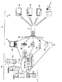
本発明は、例えば図1及び図2に示すように構成された無線LAN(Local Area Network)システム1に適用される。
【0042】
図1に示すように、公衆通信網40と接続される無線LANシステム1において、ゲートウェイとなる通信機器2(2a〜2e)、無線通信装置3、無線通信装置3が装着されるホスト機器4の間のデータ通信を実現するためにBluetooth方式を採用している。
【0043】
このBluetooth方式とは、日欧5社が1998年5月に標準化活動を開始した近距離無線通信技術の呼称である。このBluetooth方式では、最大データ伝送速度が1Mbps(実効的には721Kbps)、最大伝送距離が10m程度の近距離無線通信網を構築してデータ通信を行う。このBluetooth方式では、無許可で利用可能な2.4GHz帯のISM(Industrial Scientific Medical)周波数帯域に帯域幅が1MHzのチャネルを79個設定し、1秒間に1600回チャネルを切り換える周波数ホッピング方式のスペクトラム拡散技術を採用してホスト機器4(4a〜4d)間で電波を送受信する。
【0044】
このBluetooth方式を適用した近距離無線通信網に含まれる各ホスト機器4は、スレーブマスター方式が適用され、処理内容に応じて、周波数ホッピングパターンを決定するマスタ機器と、マスタ機器に制御される通信相手のスレーブ機器とに別れる。マスタ機器では、一度に7台のスレーブ機器と同時にデータ通信を行うことができる。マスタ機器とスレーブ機器とを加えた計8台の機器で構成するサブネットは“piconet(ピコネット)”と呼ばれる。ピコネット内、すなわち無線LANシステム1に含まれるスレーブ機器となされたホスト機器4は、同時に2つ以上のピコネットのスレーブ機器となることができる。
【0045】
図1に示す無線LANシステム1は、例えばインターネット網等の公衆通信網40とデータの送受信を行う通信機器2(2a〜2e)と、近距離無線通信網である近距離無線通信網30を介してBluetooth方式でユーザデータ等を含む制御パケットの送受信を通信機器2との間で行う無線通信装置3と、無線通信装置3との間でユーザデータ等を含む制御パケットの入出力を行うホスト機器4(4a〜4e)で構成される。
【0046】
ホスト機器4は、無線通信装置3と機械的に接続され、ユーザにより操作される電子デバイスである。ホスト機器4としては、例えばPDA(Personal Digital Assistant)4a、ディジタルカメラ4b、メール処理端末4c、EMD(Electronic Music Distribution)端末4d等がある。
【0047】
通信機器2は、近距離無線通信網30を介して無線通信装置3と制御パケット接続されるとともに公衆通信網40に接続され、無線通信装置3と公衆通信網40とを接続するためのゲートウェイである。
【0048】
この通信機器2としては、公衆通信網40と接続するためのモデム等を備えたパーソナルコンピュータ2a、例えばcdmaOne(Code Division Multiple Access)方式やW−CDMA(Wide Band−Code Division Multiple Access)方式を採用した携帯電話2b、TA/モデム2c、STB(Set Top Box)2d、例えばBluetooth方式に準じた無線通信装置3と公衆通信網40とを接続するための基地局等の準公衆システム2eがある。
【0049】
公衆通信網40としては、例えばパーソナルコンピュータ2aと電話回線を介して接続されるインターネット(Internet)網、携帯電話2bとて接続される移動体通信網(Mobile Network)、TA/モデム2cと接続されるISDN(Integrated Services Digital Network)/B(broadband)−ISDN、STB2dと接続される衛星通信網(Broadcasting)、準公衆システム2dと接続されるWLL(wireless local loop)等がある。
【0050】
公衆通信網40に含まれるインターネット網には、更に、情報提供サーバ41、メールサーバ42、EMDサーバ43、コミュニティサーバ44を含む。情報提供サーバ42では、ホスト機器4からの要求を無線通信装置3、通信機器2を介して受信し、要求に応じた情報をホスト機器4に送信する。また、メールサーバ42では、電子メールを管理し、通信機器2、無線通信装置3を介してホスト機器4との間で電子メールを送受信する。更に、EMDサーバ43では、通信機器2及び無線通信装置3を介してホスト機器4のEMD端末4dに音楽情報を送信して、音楽提供サービスを管理する。更にまた、コミュニティサーバ44では、例えばホスト機器4のディジタルカメラ4bに例えば街角情報、ニュース情報ダウンロードサービスを提供するとともに、ホスト機器4からの情報のアップロード等を管理する。
【0051】
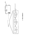
以下の説明は、説明の簡単のため、図2に示すように、移動体通信網20とデータの送受信を行う携帯電話(通信機器)2と、近距離無線通信網30を介して上記Bluetooth方式でユーザデータ等を含む制御パケットの送受信を携帯電話2との間で行う無線通信装置3と、無線通信装置3との間でユーザデータ等を含む制御パケットの入出力を行うホスト機器4とからなる無線LANシステム1について行う。
【0052】
携帯電話2は、無線通信装置3からの制御パケットに基づいて、移動体通信網20を介して公衆通信網40と接続する機能を有している。この携帯電話2は、無線通信装置3から上記Bluetooth方式の近距離無線通信網30を介して公衆通信網40と接続する旨の命令がなされる。
【0053】
ホスト機器4は、例えばパーソナルコンピュータ、ディジタルカメラ、携帯情報端末等であって、ユーザにより操作される。このホスト機器4は、無線通信装置3と接続するためのシリアルインタフェースを有し、このシリアルインタフェースにより無線通信装置3がコネクタを介して機械的に着脱可能となされている。
【0054】
無線通信装置3は、例えば図3に示すような外観構成となっている。この無線通信装置3は、USB(Universal Serial Bus)規格に準拠したUSBコネクタ51を有する。この無線通信装置3は、USBコネクタ51をホスト機器4に設けられたUSB規格に準拠した凹状接続部に挿入することで機械的に接続する。この無線通信装置3は、機械的にホスト機器4と接続されることでホスト機器4と制御パケットの入出力を行う。
【0055】
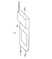
また、上記無線通信装置3は、図4に示すものであっても良い。この無線通信装置3は、筐体60内に上述したBluetooth方式の機能を実現するための半導体チップ、アンテナ、ユーザデータ記憶用のフラッシュメモリ等を収容してなる。無線通信装置3の筐体60は、板状に形成され、一方端60aよりも他方端60bの厚さが大きくなるように形成されている。
【0056】
更に、この無線通信装置3は、図5に示すようなものであっても良い。この無線通信装置3は、図4に示した無線通信装置3と同様に、筐体60内に上述したBluetooth方式の機能を実現するための半導体チップ、アンテナ、フラッシュメモリ等を収容してなる。無線通信装置3の筐体60は、板状に形成され、一方端60a及び他方端60bの厚さが同じとなるように形成されている。
【0057】
図4及び図5に示した無線通信装置3では、図6に示すように、筐体60の一方端60aに複数の接続端子61を備えている。この無線通信装置3は、複数の接続端子61を備えることでホスト機器4と電気的に接続する。この無線通信装置3は、少なくともホスト機器4に対する着脱を検出するための端子、制御パケットをホスト機器4との間で入出力するための端子等からなる10ピンの構成となされている。
【0058】
上述の図3〜図6に示したような外観構成の無線通信装置3は、図7に示すような内部構成となっている。この無線通信装置3には、図7(a)に示すように、アンテナ部3a、RFモジュール3b、ベースバンドLSI(Large Scale Integrated Circuit)3c、フラッシュメモリ3dの各チップが単一の筐体60内に収容されている。ここで、RFモジュール3bには、スイッチ部(SW)、受信部、送信部、ホッピングシンセサイザ部が格納される。また、ベースバンドLSI3cには、ベースバンド制御部、インターフェース部、個人情報記憶部、ネットワーク設定記憶部、RAM(Random Access Memory)、無線通信CPU(Central Processing Unit)、ROM(Read Only Memory)、メモリーコントローラが格納されている。なお、RFモジュール3b及びベースバンドLSI3cに格納される各部の説明は後述する。
【0059】
これらの各部3a〜3dは、図7(b)に示すように、筐体60の他方端60bから一方端60aに向かってアンテナ部3a、RFモジュール3b、ベースバンド処理部3c、フラッシュメモリ3dの順に配設されて収容されている。
【0060】
また、無線通信装置3に格納される各部3a〜3dは、図7に示すように構成される場合のみならず、図8に示すように構成されていても良い。図8によれば、3a、RFモジュール3b、ベースバンドLSI3cに加えてEEPROM(Electrically Erasable and Programmable Read Only Memory)3eを有する点で異なる。更に、図8に示す無線通信装置3は、ベースバンドLSI3cには、データバスにDMAC(Direct Memory Access Controler)、256kBのフラッシュメモリ、CPU、72kBのRAM、ベースバンド処理部、EEPROM3eとのインターフェイス回路(IIC)、既存のメモリーカード規格を適用したMSI/F(メモリースティック(商標名)・インターフェイス)がデータバスに接続されて構成され、更にメモリーコントローラが格納されている。
【0061】
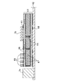
更に具体的には、無線通信装置3は、図9(a)及び図9(b)に示すように構成されている。この無線通信装置3は、筐体60内に基板62を備え、この基板62上にアンテナ部3a、RFモジュール3b、ベースバンド処理部3c、フラッシュメモリ3dを搭載し、更に他方端60b側に10ピンの端子部3eを備えている。これら各部3a〜3dは、基板62上に形成されることで、基板62を介して電気的に接続している。
【0062】
この無線通信装置3の筐体60は、例えば縦寸法t1が21.45mm、×横寸法t2が50.0mm、高さ寸法t3が2.8mmとなっている。アンテナ部3aは、基板上に一体化されたチップアンテナからなり、例えば縦寸法が9.5mm、横寸法が2.0mm、高さ寸法が1.5mmの寸法となっている。また、ベースバンド処理部3cは、縦寸法が9mm、横寸法が9mmとなっている。
【0063】
このようなアンテナ部3a、RFモジュール3b、ベースバンド処理部3c、フラッシュメモリ3d及び端子部6eを筐体60内に実装するときの実装方法について図10を参照して説明する。この図10によれば、無線通信装置3の他方端60b側から、アンテナ部3a、RFモジュール3b、ベースバンド処理部3c、フラッシュメモリ3dが基板62上に実装されて配される。以下、アンテナ部3a、機能素子、RFモジュール3b、ベースバンド処理部3cの実装方法について説明する。
【0064】
アンテナ部3aは、基板62内に実装される実装チップアンテナである。また、アンテナ部3aは、例えばBow-tieアンテナ、逆Fアンテナ、パッチアンテナ、ダイポールアンテナ等の他のアンテナであっても良い。図11に示すように、筐体60上に配設された基板62に一体となって形成され、基板62に埋め込まれた状態で実装される。この無線通信装置3では、使用するアンテナ部3aの種類に応じて、筐体60の他方端60bの形状を図4又は図5のように変形させる。
【0065】
RFモジュール3b及びベースバンド処理部3cは、図11及び図12に示すように、基板62上に形成された多層基板63上に実装される。ここで、多層基板63は、4層構造とされ、各基板間の導通を図るため、内壁に金属膜が形成されたスルーホール64が形成される。これにより、無線通信装置3では、アンテナ部3a、RFモジュール3b、ベースバンド処理部3c、フラッシュメモリ3d、端子部3e間の電気的導通を確保し、各部間でパケットの入出力を行っている。
【0066】
RFモジュール3bは、多層基板63上にフリップチップ(Flipchip)技術を用い、フリップチップ接続部65を介して多層基板63上に形成された金属パターン上に実装される。
【0067】
ここで、RFモジュール3bが実装される多層基板63には、キャパシタ66及び共振器(フィルタ)67が基板間に内蔵して実装されるとともに、インダクタ68が裏面側に実装される。更に、多層基板63上には、チップ部品69が実装される。
【0068】
また、ベースバンド処理部3cを多層基板63上に実装するときには、図12に示すように、はんだボール71上に配線基板72、ベースバンド処理部3c、フリップチップ接続部73、フラッシュROM74が順次積層されてなり、一体化された状態で積層基板73上に、フリップチップ技術を用いて実装される。ここで、ベースバンド処理部3cは、隣接するRFモジュール3b及びフラッシュメモリ3dとの電通を、ワイヤボンディング技術を用いてワイヤ75を接続してことで確保している。更に、ベースバンド処理部3cを実装するときには、他の部分との電波干渉を防止すべく、電波吸収体材料76が形成される。
【0069】
更に、フラッシュメモリ3dを基板62上に実装するときには、図13に示すように、超薄型基板77と、超薄型基板77間に設けられたはんだボール78を交互に積層した構成を有する多層基板を用いる。各超薄型基板77は、はんだボール78に支持されることで所定の間隔を有して積層されている。そして、フラッシュメモリ3dを実装するときには、フレキ実装技術、フリップチップ技術をを用い、フリップチップ接続部79を介して超薄型基板77間にフラッシュメモリ3dを実装する。ここでフラッシュメモリ3dは、薄型化チップで構成されることで、4枚のチップとなされている。
【0070】
このように実装されるRFモジュール3b及びベースバンド処理部3cは、外部からの電波を防止すべく、図14に示すように、電波吸収体モールド3fで覆われる。
【0071】
このように、無線通信装置3は、上述したように、アンテナ部3a、RFモジュール3b、ベースバンド処理部3c、フラッシュメモリ3dを基板62上に実装する。これにより、他方端60bから一方端60aに向かって、アンテナ部3a、RFモジュール3b、ベースバンド処理部3c、フラッシュメモリ3dが順次実装することができる。更に、上述したような手法を用いることにより、アンテナ部3a、RFモジュール3b、ベースバンド処理部3c、フラッシュメモリ3dを厚さ2.8mm、縦50.0mm、横2.4mmの寸法を有する筐体60内に収容することができる。
【0072】
このような無線通信装置3は、例えば図15に示すような態様でパーソナルコンピュータ等のホスト機器4に装着される。すなわち、無線通信装置3は、筐体60の一方端60a側に設けられている出力端子61がパーソナルコンピュータの凹状接続部4fに接続されたとき、一方端60aがパーソナルコンピュータの凹状接続部4f内に隠れ、他方端60bがパーソナルコンピュータの外部に露呈する。このような無線通信装置3は、他方端60bが外部に露呈するようにパーソナルコンピュータと接続されることで、少なくともアンテナ部3aを覆っている筐体60の一部を外部に露呈する。
【0073】
また、この無線通信装置3は、例えば図4に示すような外観構成の筐体60を備えるときには、厚さ寸法が一方端60aと比較して大きい他方端60bをパーソナルコンピュータから露呈して接続する。
【0074】
つぎに、無線LANシステム1を構成する携帯電話2、無線通信装置3及びホスト機器4の実装するプロトコルスタックについて図2を参照して説明する。
【0075】
携帯電話2は、下位の3つのレイヤとしてBluetooth方式の無線LANシステム1を実現するための物理レイヤ(PHY)、メディアアクセス制御レイヤ(MAC)、論理リンク制御レイヤ(LLC)を有するプロトコルスタック11を実装している。携帯電話2は、上記の下位の3つのプロトコルを用いることで無線通信装置3と近距離無線通信網30を介して制御パケットの送受信を行う。
【0076】
また、携帯電話2は、下位の3つのレイヤに対する上位レイヤとしてW−CDMA(Wide Band−Code Division Multiple Access)プロトコルを実装している。この携帯電話2は、W−CDMAプロトコルを実装し、無線通信装置3によりデータ通信モードとされることで移動体通信網20を介して公衆通信網40への接続を実現する。なお、この携帯電話2は、上記W−CDMAプロトコルとは異なるプロトコルを実装していても良い。
【0077】
無線通信装置3は、無線送受信機能とプロトコル制御機能を備え、上記携帯電話2と近距離無線通信網30を介して制御パケットの送受信を行うとともに、ホスト機器4とデータの入出力がなされる。
【0078】
この無線通信装置3は、上述の携帯電話2と同様に、下位の3つのレイヤとしてBluetooth方式の物理レイヤ(PHY)、メディアアクセス制御レイヤ(MAC)、論理リンク制御レイヤ(LLC)を有するプロトコルスタック12を実装している。無線通信装置3は、上記の下位の3つのプロトコルを用いることで近距離無線通信網30を介して携帯電話2とデータの送受信を行う。なお、この無線通信装置3の更に詳細な構成、及び処理内容については後述する。
【0079】
また、この無線通信装置3は、近距離無線通信網30を構成するための下位3つのレイヤに対する上位レイヤとして、PPP(Point to Point Protocol)、IP(Internet Protocol)、TCP(Transmission Control Protocol)を実装している。この無線通信装置3は、PPPに準じた処理を実行して公衆通信網40に含まれるインターネットサービスプロバイダにダイヤルアップ接続し、IP及びTCPに準じた処理を実行して公衆通信網40に含まれるWWW(World Wide Web)サーバに接続するように携帯電話2を制御する。
【0080】
更に、この無線通信装置3は、TCPレイヤに対する上位レイヤとして、ホスト機器4と物理的に接続するためのHOSTI/Fレイヤを実装している。このHOSTI/Fレイヤは、ホスト機器4と接続してユーザデータの入出力を行うレイヤである。このHOSTI/Fレイヤでは、例えばUSBや、フラッシュメモリに格納するデータのみを入出力するための既存のインターフェイスが行う処理を行うレイヤである。
【0081】
このホスト機器4は、上述の無線通信装置3の最上位レイヤに実装されているHOSTI/Fレイヤに対応したHOSTI/Fレイヤと、HOSTI/Fレイヤに対する上位レイヤとしてアプリケーション(application:AP)レイヤとを実装している。このホスト機器4は、HOSTI/Fレイヤを実装することで、アプリケーション(AP)で生成したユーザデータを無線通信装置3との間で入出力する。このホスト機器4に格納されているアプリケーションレイヤとしては、パーソナルコンピュータである場合にはインストールされているアプリケーションソフトウェアに相当する。
【0082】
また、このホスト機器4は、例えばユーザが操作することで操作入力信号を生成する。このホスト機器4は、例えば無線通信装置3及び近距離無線通信網30を介して携帯電話2と接続する旨の操作入力信号を生成して、操作入力信号に従った制御コマンドを無線通信装置3に出力する。これにより、ホスト機器4は、携帯電話2が公衆通信網40と接続することで、近距離無線通信網30及び移動体通信網20からなる公衆網を介して公衆通信網40と接続する。
【0083】
更に、ホスト機器4は、無線通信装置3が装着されることで、HOSTI/Fレイヤを介してシリアルインタフェースにより無線通信装置3とユーザデータを含む制御パケットの入出力を行う。
【0084】
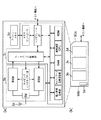
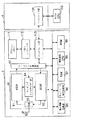
次に、上述した無線LANシステム1を構成する無線通信装置3及びホスト機器4のブロック図を図16に示す。
【0085】
無線通信装置3は、無線LANシステム1における無線通信を行う通信制御部81と、無線LANシステム1を構成する各部とユーザデータ等の送受信をするアンテナ部82と、無線制御部71で行う通信を制御するベースバンド制御部83と、ホスト機器4とユーザデータ等を含む制御パケットの入出力を行うインタフェース部74とを備える。ここで、通信制御部81は上述のRFモジュール3bに対応し、ベースバンド制御部83は上述のベースバンド処理部3cに対応する。
【0086】
アンテナ部82は、2.4GHz帯(2.402GHz〜2.480GHz)の信号を送信/受信するためのアンテナからなる。このアンテナ部82は、通信制御部81からのデータを近距離無線通信網30を介して携帯電話2に送信するとともに、携帯電話2から近距離無線通信網30を介して信号を受信して通信制御部81に出力する。ここで、アンテナ部82は、上述のアンテナ部3aに対応する。
【0087】
このアンテナ部82で送受信される近距離無線通信網30におけるデータは、所定のビット数からなり、ユーザデータと制御データとからなる制御パケットを最小単位として送受信される。
【0088】
上記通信制御部81は、アンテナ部82からの制御パケットを受信するための処理を行う受信部81と、アンテナ部82から制御パケットを送信するための処理を行う送信部82と、送信部82からの制御パケットをアンテナ部82を介して送信するか又はアンテナ部82からの制御パケットを受信部81に出力するかを切り換えるスイッチ部83と、受信部81及び送信部82における制御パケットについて周波数ホッピングによるスペクトラム拡散を行うホッピングシンセサイザ部84とを備える。
【0089】
スイッチ部83は、後述するCPU(Central Processing Unit)69からの制御信号に応じて動作し、アンテナ部82から制御パケットを受信するときにはアンテナ部82からの制御パケットを受信部81に出力するように動作し、アンテナ部82から制御パケットを送信するときには送信部82から制御パケットをアンテナ部82に出力するように動作する。
【0090】
受信部81は、スイッチ部83からの制御パケットを受信し、ベースバンド制御部83に出力する。また、この受信部81は、ホッピングシンセサイザ部84によりホッピング周波数パタンが指定され、スイッチ部83から制御パケットを受信するときにおける周波数パタンに従って制御パケットを受信してベースバンド制御部83に出力する。このとき、受信部81は、ホッピングシンセサイザ部84でパケット単位で指定された周波数パタンを乗算する等の処理を行ってベースバンド制御部83に出力する。
【0091】
送信部82は、アンテナ部82から近距離無線通信網30を介して携帯電話2に出力する制御パケットとして、ベースバンド制御部83で生成され一次変調されたパケット単位の制御パケットが入力され、スイッチ部83に出力する。また、この送信部82は、ホッピングシンセサイザ部84により周波数パタンが指定され、当該周波数パタンに従って制御パケットをスイッチ部83に出力する。このとき、送信部82は、ホッピングシンセサイザ部84で指定された周波数パタンにより周波数変換をパケット単位で施して送信する処理を行う。
【0092】
ホッピングシンセサイザ部84は、ベースバンド制御部83からの周波数ホッピングのホッピングパターンが指定される。このホッピングシンセサイザ部84は、アンテナ部82から制御パケットを受信するときにはベースバンド制御部83で指定されたホッピングパターンの周波数パタンを受信部81に出力する。また、このホッピングシンセサイザ部84は、アンテナ部82から制御パケットを送信するときには送信部82でベースバンド制御部83からのデータに周波数変換を施すための周波数パタンを送信部82に出力する。このホッピングシンセサイザ部84は、受信部81及び送信部82に同じ周波数パタンを指定するようにベースバンド制御部83に制御される。
【0093】
このホッピングシンセサイザ部84は、例えば、1MHzごとに分割された79チャネル上(2.402GHz〜2.480GHz)に毎秒1600回の周波数ホッピングを行うように周波数変換を行う。
【0094】
上記ベースバンド制御部83は、後述する無線通信CPU89からの制御信号に従って、以下に示すような処理を行う。
【0095】
このベースバンド制御部83は、受信部81からパケット単位の制御パケットが入力され、周波数ホッピングにより周波数変調された制御パケットを復調する処理を行う。また、このベースバンド制御部83は、アンテナ部82から制御パケットを送信するときには、送信する制御パケットについて一次変調を施して送信部82に出力する。
【0096】
更に、このベースバンド制御部83は、ホッピングシンセサイザ部84にホッピングパターンを与えることにより、ホッピングシンセサイザ部84を制御する。これにより、ベースバンド制御部83は、無線通信装置3から送信する制御パケットの送信タイミングを制御するとともに、受信する制御パケットの受信タイミングを制御する。このベースバンド制御部83は、ホッピングパターンとして、例えばf(k)、f(k+1)、f(k+2)、・・・の周波数パタンを所定時間ごとにホッピングシンセサイザ部84に与える。
【0097】
更にまた、このベースバンド制御部83は、制御パケットを所定のパケットフォーマットに変換して制御パケット単位で受信部81に出力するとともに、送信部82からの所定のパケットフォーマットの制御パケットを分解する処理を行ってインタフェース部74又はデータバスを介して無線通信CPU89に出力する。
【0098】
上記所定のパケットフォーマットとは、例えば図17に示すように、SYNC(同期)データと、PID(Paket ID)データと、PAYLOADと、CRC(Cyclic Redundancy Code)データとからなり、基本的にはUSB規格のバルク転送方式に準拠している。
【0099】
上記SYNCデータは、パケットの始まりを示す同期ワードである。
【0100】
上記PIDデータは、パケットを識別するための識別子であり、パケットの種類を示すデータである。
【0101】
上記PAYLOADは、制御データ、ユーザデータが格納される領域である。
【0102】
上記CRCデータ94は、上記PAYLOADに関して付与される誤り検出用のCRCパリティである。
【0103】
インタフェース部74は、無線通信CPU89からの制御信号に従って動作する。このインタフェース部74は、アンテナ部82から受信した制御パケットが通信制御部81、ベースバンド制御部83を介して入力され、当該制御パケットについて所定の変換処理を施してホスト機器4に出力する。また、このインタフェース部74は、アンテナ部82から制御パケットを送信するときには、ホスト機器4を介して入力された制御パケットをベースバンド制御部83に出力する。
【0104】
このインターフェース部84は、上述した図5及び図6に示すように、例えば、メモリースティック(登録商標)と同様の仕様を有するシリアルインターフェイスとなっていても良い。
【0105】
更に、この無線通信装置3は、ユーザごとに与えられる個人情報を記憶する個人情報記憶部85と、ホスト機器4が近距離無線通信網30や公衆通信網40等のネットワークと接続するために必要な情報を示すネットワーク設定情報を記憶するネットワーク設定記憶部86とを備える。
【0106】
個人情報記憶部85には、ホスト機器4を保有するユーザのメールアドレス、アクセスポイントに接続するためのユーザID、パスワード(PPP接続用)等が個人情報として格納される。この個人情報記憶部85は、無線通信CPU89により読み込まれるとともに、その内容が制御される。
【0107】
更に、個人情報記憶部85には、例えば無線通信装置3が実行するアプリケーションとして電子メールアプリケーションを想定した場合には、電子メール送信先の電子メールアドレス一覧(アドレス帳)を示す情報、送受信履歴を示す情報、文字入力機能の乏しいホスト機器4(例えばディジタルカメラ)に対して入力の簡略化を図るための定型文一覧を示す情報、送信した電子メールの文章の末尾に付加するシグネチャ情報、電子メールを受信したときに未読又は既読の管理を行うためのメールユニークIDを示す情報等を格納しても良い。
【0108】
更にまた、この個人情報記憶部85には、SIM(Subscriber Identification Module)情報を格納しても良い。この個人情報記憶部85に格納される上記SIM情報とは、ユーザを識別するために必要とされる情報であって、セキュリティ性の向上を図り、無線通信装置3の内部で暗号化処理された情報である。このSIM情報は、例えば上記ユーザID、ユーザパスワード、個人のメールボックスにアクセスするためのメールID、メールパスワード、ユーザのメールアドレス、無線通信装置3自体の利用権限を確認するための個人認証用パスワード等が暗号化された情報である。
【0109】
ネットワーク設定記憶部86には、ホスト機器4が公衆通信網40のインターネットサービスプロバイダとダイヤルアップ接続するときに必要となるサーバアドレス、アクセスポイント電話番号等がネットワーク設定情報として格納され、無線通信CPU89により読み込まれるとともに、その内容が制御される。
【0110】
更にまた、この無線通信装置3は、データバスに接続されたRAM(Random Access Memory)87、ROM(Read Only Memory)88、無線通信CPU89を備える。
【0111】
上記無線通信CPU89は、データバスを介して無線通信装置3を構成する各部を制御するため制御プログラムをROM88から読み込むことで制御信号を生成する。無線通信CPU89は、RAM87を作業領域として随時データを格納して制御プログラムを実行して制御信号を生成する。これにより、無線通信CPU89は、ベースバンド制御部83、通信制御部81及びインタフェース部74を制御して無線LANシステム1を構成する他の機器との通信を制御する制御パケットを生成するとともに、インタフェース部74を介してホスト機器4と制御パケットの送受信を行う。なお、この無線通信CPU89が制御プログラムを実行して行う処理内容の詳細については後述する。
【0112】
ホスト機器4は、無線通信装置3のインタフェース部74とデータの入出力を行うインタフェース部101と、データバスを介してインタフェース部101等を制御するホストCPU102を備える。
【0113】
インタフェース部101は、上述した無線通信装置3のインタフェース部74とユーザデータを含む制御パケット等の入出力を行うことができるUSB等のシリアルインタフェースからなる。
【0114】
このインターフェース部91は、上述した図5及び図6に示すような無線通信装置3のインターフェイス部74との間で制御パケットの送受信を行うことができるシリアルインターフェイスとなっていても良い。
【0115】
ホストCPU102は、ホスト機器4で生成したユーザデータやユーザにより操作されることで生成した操作入力信号等の制御データを含む制御パケットを生成する。このホストCPU102は、アプリケーションレイヤにおける処理を実行することでユーザデータ及び制御データを生成する。このホストCPU102は、HOSTI/Fレイヤにおける処理を実行することで、制御パケットを生成し、インタフェース部101を介して無線通信装置3に制御パケットを出力する。
【0116】
ここで、無線通信装置3とホスト機器4とは、マスタ/スレーブの関係にあり、ホスト機器4側がマスタとなり、無線通信装置3がスレーブとなっている。すなわち、無線通信装置3は、ホストCPU102からの制御パケット等に従って動作する。例えば無線通信装置3からホスト機器4にユーザデータの出力を行うときであっても、無線通信装置3は、ホスト機器4とを接続するシリアルデータラインの使用権を得た旨の制御パケットをホストCPU102から無線通信CPU89に入力されたときにのみホスト機器4側にユーザデータを出力することができる。
【0117】
より具体的には無線通信装置3とホスト機器4との間でユーザデータを送受信するときには、ホスト機器4から所定の時間間隔で無線通信装置3の無線通信CPU89に上記図17に示したパケットフォーマットの制御パケットを出力することにより行う。
【0118】
すなわち、ホスト機器4のホストCPU102は、無線通信装置3側にユーザデータを送信するときには上記PIDデータとして“OUTトークンパケット”を示す制御データを格納した制御パケットを生成して無線通信CPU89に出力する。また、ホストCPU102は、無線通信装置3側からのユーザデータを受け付け可能であるときには上記PIDデータとして“INトークンパケット”を示す制御データを格納した制御パケットを生成して無線通信CPU89に出力する。これにより、無線通信装置3とホスト機器4との間でユーザデータを含む制御パケットを双方向に入出力することができる。
【0119】
更に、ホストCPU102は、無線通信装置3の制御内容に応じてPIDデータの内容を変化させた制御パケットを生成して出力することで、無線通信装置3の動作モードを制御する。すなわち、ホストCPU102は、制御パケットを無線通信CPU89に出力することで、無線通信装置3を通信アイドルモード、メモリモード、OUTトランザクションモード、INトランザクションモードに切り換える。
【0120】
図18に、ホストCPU102により動作モードが切り換えられる無線通信装置3の状態遷移図を示す。
【0121】
ここで、無線通信装置3は、通常、ホスト機器4から無線通信装置3側に制御パケットが送信されてなく、通信処理を待機している動作モードである通信アイドルモード(ステップST1)となされている。
【0122】
無線通信CPU89は、ホストCPU102からPIDデータとして“OUTトークンパケット”を示す制御データが格納された制御パケットが入力されたときには、ホスト機器4側からユーザデータが送信されてくる動作モードであるOUTトランザクションモード(ステップST2)に移行する。
【0123】
上記OUTトランザクションモードにおいて、無線通信CPU89は、制御パケットのCRCデータによりPAYLOADにエラーが含まれていないと判定したとき、PIDデータとして“ACK(acknowledgement)”を示す制御データを格納した制御パケットを生成し、ホスト機器4に送信して(ステップST2a)、通信アイドルモード(ステップST1)に戻る。
【0124】
また、無線通信CPU89は、上記OUTトランザクションモードにおいて、制御パケットのCRCデータによりPAYLOADにエラーが含まれていると判定したとき、PIDデータとして“NAK(negativeacknowledgement)”を示す制御データを格納した制御パケットを生成し、ホスト機器4に送信して(ステップST2b)、通信アイドルモード(ステップST1)に戻る。
【0125】
更に、無線通信CPU89は、上記OUTトランザクションモードにおいて、制御パケットを受信することができないとき、PIDデータとして“STALL”を示す制御データを格納した制御パケットを生成して、ホスト機器4に送信して(ステップST2c)、通信アイドルモード(ステップST1)に戻る。
【0126】
また、無線通信CPU89は、ホストCPU102からPIDデータとして“INトークンパケット”を示す制御データが格納された制御パケットが入力されたときには、通信アイドルモード(ステップST1)から、ホスト機器4側から無線通信装置3側にユーザデータを送信することが許可された動作モードを示すINトランザクションモード(ステップST3)に移行する。
【0127】
そして、無線通信CPU89は、INトランザクションモード(ステップST3)となされると、ユーザデータを含む制御パケットを生成して、ユーザデータの送信を行う(ステップST3a)。このとき、無線通信CPU89は、制御パケットごとにPIDデータとして“DATA0”、“DATA1”とトグルとして順次変化させた制御データを格納してホストCPU102に送信する。これにより、無線通信CPU89とホストCPU102とは相互に入出力する制御パケットの送信確認を行う。
【0128】
そして、無線通信CPU89は、ホスト機器4側に制御パケットを送信した(ステップST3a)ことに応じ、ホストCPU102からの応答を示す制御パケットが送信されるまで待機状態となる。ホストCPU102から無線通信CPU89に送信される応答は、無線通信装置3側からホスト機器4側にデータが確実に送信されたことを示すACK受信(ステップST3b)、無線通信装置3側からホスト機器4側にデータが送信されなかったことを示すNAK受信(ステップST3c)、ホスト機器4側がデータを受信する状態ではないことを示すSTALL受信(ステップST3d)がある。
【0129】
そして、無線通信CPU89は、ACK受信、NAK受信又はSTALL受信を示す制御データをPAYLOADに格納した制御パケットを受信したことに応じて、通信アイドルモード(ステップST1)に移行する。
【0130】
更に、無線通信CPU89は、ホストCPU102からPIDデータとして“ネットワーク/個人情報設定モード”を示す制御データが格納された制御パケットが入力されたときには、通信アイドルモード(ステップST1)から、ネットワーク/個人情報設定モード(ステップST4)に移行する。
【0131】
そして、無線通信CPU89は、ネットワーク/個人情報設定モードにおいて、個人情報記憶部85に格納された個人情報及びネットワーク設定記憶部86に格納されたネットワーク設定情報の読み込み、書き込み、更新、消去等の処理を行って通信アイドルモード(ステップST1)に戻る。このとき、無線通信CPU89は、例えばPAYLOADに格納されている制御データに従って、個人情報及びネットワーク設定情報の読み込み、書き込み、更新、消去等の処理を行う。
【0132】
また、ホストCPU102は、無線通信装置3に近距離無線通信網30を介して公衆通信網40に接続するときには、その旨を示す制御パケットを無線通信CPU89に送信することで、公衆通信網40のインターネットサービスプロバイダとの接続を制御する。なお、無線通信装置3から近距離無線通信網30、移動体通信網20を介し、ホスト機器4と公衆通信網40とを接続するときの処理手順については後述する。
【0133】
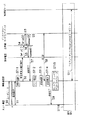
次に、上述した無線LANシステム1において、ホスト機器4と公衆通信網40のWWWサーバとを接続するときの無線通信CPU89が行う処理について図19のフローチャートを参照して説明する。なお、この図19は、ホスト機器4、無線通信装置3、携帯電話2、移動体通信網20及び公衆通信網40等からなる公衆網、公衆通信網40に含まれるインターネットサービスプロバイダ、公衆通信網40に含まれるWWWサーバ間で送受信されるデータ及び主として無線通信CPU89の処理内容を示す。
【0134】
この図19によれば、先ず、ホストCPU102は、ホスト機器4から公衆通信網40に含まれるWWWサーバにユーザデータを発信する発信要求S1を示す制御パケットを無線通信CPU89に送信する。
【0135】
次に、無線通信CPU89は、発信要求S1に応じ、ステップST11において、例えばROM88に格納されたPPPを起動する。
【0136】
そして、無線通信CPU89は、ネットワーク設定記憶部86に格納されているアクセス先のインターネットサービスプロバイダの電話番号を参照して、発信要求及び電話番号S2がPAYLOADに格納された制御パケットを生成する処理を行い、近距離無線通信網30を介して携帯電話2に発信要求及び電話番号S2を送信する。
【0137】
次に、携帯電話2は、無線通信装置3からの発信要求及び電話番号S2に応じて、公衆網に第1の呼設定S3(Set up(1))を送信する。これに応じ、公衆網では、例えばルータ等の複数の中継器を介して、第1の呼設定S3と同様の内容の第2の呼設定S4(Set up(2))をインターネットサービスプロバイダに送信する。ここで、公衆網は、インターネットサービスプロバイダの応答により、インターネットサービスプロバイダから接続を確認するための第1の接続情報S5(Connect(2))が返信されて受信する。そして、公衆網は、第1の接続情報S5を受信したことに応じ、第1の接続情報S5と同様の内容を示す第2の接続情報S6((Connect(1))を携帯電話2に送信する。
【0138】
そして、携帯電話2は、近距離無線通信網30を介してインターネットサービスプロバイダとの接続が完了したことを示す接続完了情報S7を無線通信装置3に送信する。
【0139】
次のステップST12において、無線通信CPU89は、携帯電話2から受信した接続完了情報S7に応じて、PPPとしてリンク確立フェーズに移行する。
【0140】
次のステップST13において、無線通信CPU89は、PPPによる認証処理を行う。このとき、無線通信CPU89は、個人情報記憶部85からユーザID及びパスワードを読み出し、PPPによって携帯電話2、公衆網経由でインターネットサービスプロバイダと互いに認証するための認証情報S8を送受信することで認証処理を行う。
【0141】
次のステップST14において、無線通信CPU89は、インターネットサービスプロバイダとの間で認証情報S8を送受信することで認証処理が終了し、認証確立フェーズとなり、無線通信装置3とインターネットサービスプロバイダとの接続が完了したことを示す接続完了情報S9を含む制御パケットをホスト機器4のホストCPU102に出力する。
【0142】
次のステップST15において、無線通信CPU89は、上述のステップST14において認証処理が終了したことに応じて、ネットワークレイヤプロトコルフェーズに移行する。すなわち、無線通信CPU89は、プロトコルスタックに実装されているIP、TCPに従った処理を実行することで公衆通信網40との接続を行う。
【0143】
次のステップST16において、ホストCPU102は、無線通信装置3とユーザデータを制御パケットのPAYLOADに格納してユーザデータS10の入出力を行い、TCP及びIPによりユーザデータS10に制御情報を付加することでパケット化して無線通信装置3と公衆通信網40のWWWサーバとの間でパケット化されたユーザデータS11の送受信を行う。
【0144】
上述したような処理を行う無線通信装置3によれば、個人情報及びネットワーク設定情報を格納している個人情報記憶部85及びネットワーク設定記憶部86を備えているので、無線通信CPU89によりPPPを起動し個人情報及びネットワーク管理情報を用いてインターネットサービスプロバイダと接続することができる。また、この無線通信装置3によれば、IP及びTCPを起動し個人情報及びネットワーク設定情報を用いてWWWサーバとの間でカプセル化されたユーザデータを送受信するとともに制御パケットによりホスト機器4と接続することで、ホスト機器4とWWWサーバとを接続することができる。
【0145】
したがって、この無線通信装置3によれば、ホスト機器4側に個人情報及びネットワーク設定情報を格納する必要がないのでホスト機器4ごとに公衆通信網40と接続するための各種設定を行う必要がなく、各ホスト機器4について公衆通信網40等への接続するためのネットワーク設定等を簡便にすることができる。したがって、この無線LANシステム1によれば、各ホスト機器4に無線通信装置3を装着することで、各ホスト機器4とWWWサーバとの接続設定を行うことができる。
【0146】
また、この無線通信装置3によれば、個人情報記憶部85及びネットワーク設定記憶部86に各ホスト機器4で共通のパケット構造の制御パケットを送受信することで、ホスト機器4の種類を問わず、ホスト機器4と公衆通信網40との間でデータの送受信を行うことができる。
【0147】
更に、この無線通信装置3によれば、ホスト機器4と公衆通信網40との間でデータを送受信を行うときに、ホスト機器4の種類を問わず、公衆通信網40に含まれるサーバ等のアドレス情報や送受信履歴等を一元管理することで各ホスト機器4で個人情報及びネットワーク設定情報を共有することができ、各ホスト機器4ごとに個人情報やネットワーク設定情報を設定する手間を省くことができる。
【0148】
図20に示すように、ホスト機器4として、携帯情報端末4a、パーソナルコンピュータ4b、変換アダプタ4c、ゲーム機器4d、テレビジョン4eが存在する無線LANシステム1において、無線通信装置3は、例えばホスト機器4cに装着されることで、無線通信装置3を装着することができないゲーム機器4dであっても、ホスト機器4dとWWWサーバとを接続することができる。
【0149】
このような無線LANシステム1において、例えばディジタルカメラのように操作や表示能力が乏しい機器とWWWサーバとの接続するための設定を行うときには、ディジタルカメラで各種設定を行う必要はなく、ディジタルカメラと比較して高度のマンマシンインタフェースを備えた携帯情報端末4aやパーソナルコンピュータ4bを用いて、無線通信装置3に格納する個人情報及びネットワーク設定情報を設定することができる。これにより、無線通信装置3を含む無線LANシステム1によれば、パーソナルコンピュータ4bでネットワーク設定を行った無線通信装置3をディジタルカメラに装着することでディジタルカメラとWWWサーバとの接続をすることができ、例えば操作や表示機能が乏しいディジタルカメラ等であっても、ネットワーク設定等を簡便に行うことができる。
【0150】
更に、例えばパーソナルコンピュータ4bを持っていないユーザにおいては、ゲーム機器4dとテレビジョン4eとを組み合わせ、変換アダプタ4cを介して個人情報及びネットワーク設定情報を設定しても良い。ここで、無線通信装置3とゲーム機器4dとは直接信号の入出力を行うことができないので、USB又は後述するメモリ機能付き無線通信装置のインタフェースとゲーム機器4dのインタフェースとの変換アダプタ4cを用いて、無線通信装置3とゲーム機器4dとの信号の入出力を行う。これにより、ネットワーク設定等を簡便に行うことができる。また、ゲーム機器4d及びテレビジョン4e等の他のホスト機器4でネットワーク設定を行った無線通信装置3をディジタルカメラに装着することでディジタルカメラとWWWサーバとの接続を可能とし、ディジタルカメラを例えば動画ビューアとして使用することができる。
【0151】
また、上述した無線通信装置3によれば、ホスト機器4側に無線LANシステム1を構築するための機能及び公衆通信網40に接続させるための機能を内蔵させることが不要となり、ホスト機器4の単体コストを低減させることができる。
【0152】
なお、ホストCPU102は、無線通信装置3に実装されたPPP、IP、TCPを起動してインターネット接続を制御する一例のみならず、ホスト機器4の内部にPPP、IP、TCPを実装して、無線通信装置3に実装されたプロトコルを用いてインターネット接続するか、ホスト機器4に実装されたプロトコルを用いてインターネット接続するかを選択しても良い。
【0153】
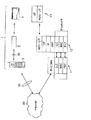
すなわち、図2に示す無線LANシステム1の一例とは異なり、図21に示すように、ホスト機器4側に実装されているプロトコルスタック14にネットワーク設定を行うためのPPP、IP、TCPを備えていても良い。
【0154】
このようなホスト機器4を備えた無線LANシステム1により、公衆通信網40との接続をするときにおいて、ホスト機器4に格納されたPPP、IP、TCPを使用するときには無線通信装置3に実装されているPPP、IP、TCPを起動せず、無線通信装置3のHOSTI/FレイヤとLLCレイヤとの間で制御パケットを入出力する経路L1を用いる。これにより、無線通信装置3では、PPP、IP、TCPを起動するために要していたメモリ空間に他のデータ等を記憶させるのに使用することができる。一方、無線通信装置3に格納されたPPP、IP、TCPを使用するときにはホスト機器4に実装されているPPP、IP、TCPを使用することなく、ホスト機器4のAPレイヤとHOSTI/Fレイヤとの間で制御パケットを入出力する経路L2を用いる。
【0155】
図21に示した無線LANシステム1において、ホスト機器4と公衆通信網40のWWWサーバとを接続するときの他の処理手順について図22及び図23を参照して説明する。なお、以下に説明する図22及び図23の説明において、図19に示した処理と同様の処理については同一符号を付することでその詳細な説明を省略する。
【0156】
図22によれば、先ず、ホスト機器4と公衆通信網40のWWWサーバとの接続を要求する発信要求S21がホストCPU102から無線通信装置3に出力される。
【0157】
次にステップST21において、無線通信装置3の無線通信CPU89は、発信要求S21のみが送信されたときには、例えばROM88に格納されて内部に実装した内部プロトコルを使用すると判定する。そして、無線通信CPU89では、上述の図19で説明した処理と同様にステップST11〜ステップST16までの処理を行うことで、公衆通信網40のインターネットサービスプロバイダと接続するとともに、ホスト機器4とWWWサーバとの接続を行う。すなわち、無線通信CPU89は、経路L1を用いて制御パケットについて、プロトコルスタック14の各レイヤにおける処理を行う。
【0158】
一方、無線通信CPU89は、図23に示すように、ステップST31において、ホストCPU102により例えば内蔵されたROMに格納した内部プロトコルであるPPPを起動する処理がなされ、発信要求及びインターネットサービスプロバイダの電話番号S31が入力されたときには、ステップST21において内部プロトコルを使用しないと判定する。すなわち、無線通信CPU89は、経路L2を用いて制御パケットについて、プロトコルスタック12の各レイヤにおける処理を行う。
【0159】
そして、ホスト機器4は、上述の図19を用いて説明したように、発信要求及び電話番号S31と同様の内容の発信要求及び電話番号S2を携帯電話2に近距離無線通信網30を介して無線通信装置3に送信させて以下の処理を行う。
【0160】
すなわち、ホスト機器4は、公衆網に第1の呼設定S3(Set up(1))を送信し、第1の呼設定S3と同様の内容の第2の呼設定S4を公衆網からインターネットサービスプロバイダに送信する。ここで、公衆網は、インターネットサービスプロバイダの応答により、インターネットサービスプロバイダから接続を確認するための第1の接続情報S5が返信されて受信する。そして、第1の接続情報S5を受信したことに応じ、第1の接続情報S5と同様の内容を示す第2の接続情報S6を公衆網から携帯電話2に送信し、近距離無線通信網30を介してインターネットサービスプロバイダとの接続が完了したことを示す接続完了情報S7を携帯電話2から無線通信装置3に送信する。無線通信装置3は、接続完了情報S7と同様の内容を示す接続完了情報S32を制御パケットとして無線通信装置3からホスト機器4に出力する。
【0161】
次のステップST32において、ホストCPU102は、携帯電話2から受信した接続完了情報S32に応じて、PPPとしてリンク確立フェーズに移行する。
【0162】
次のステップST33において、ホストCPU102は、PPPによる認証処理を行う。このとき、ホストCPU102は、無線通信装置3の個人情報記憶部85からユーザID及びパスワードを制御パケットとしてインタフェース部74及びインタフェース部101を介して入力し、PPPによって無線通信装置3、携帯電話2及び公衆網を経由してインターネットサービスプロバイダと互いに認証するための認証情報S33を送受信することで認証処理を行う。
【0163】
次のステップST34において、ホストCPU102は、インターネットサービスプロバイダとの間で認証情報を送受信することで認証処理が終了し、認証確認フェーズとなる。
【0164】
次のステップST35において、ホストCPU102は、上述のステップST34において認証処理が終了したことに応じて、ネットワークレイヤプロトコルフェーズに移行する。すなわち、ホストCPU102は、プロトコルスタックに実装されているIP、TCPを用いて公衆通信網40との接続を行う。
【0165】
次のステップST36において、ホストCPU102は、TCP及びIPによりユーザデータに制御情報を付加することでパケット化して無線通信装置3を介して公衆通信網40のWWWサーバとの間でパケット化されたユーザデータS34の送受信を行う。
【0166】
したがって、このような処理を行うことができる無線LANシステム1によれば、図23におけるステップST21において、ホスト機器4に格納されている内部プロトコルを使用すると判定してホスト機器4により公衆通信網40との接続を行う場合であっても、個人情報及びネットワーク設定情報を無線通信装置3の個人情報記憶部85及びネットワーク設定記憶部86からインタフェース部74及びインタフェース部101を介してホストCPU102に入力するので、ホスト機器4側に個人情報及びネットワーク設定情報を格納せず、ホスト機器4ごとに公衆通信網40との接続するための設定を行う必要なく、各ホスト機器4について公衆通信網40等への接続するためのネットワーク設定等を簡便にすることができる。
【0167】
つぎに、上述した図7に示したように、フラッシュメモリを備えるメモリ機能付き無線通信装置200について説明する。このメモリ機能付き無線通信装置200は、例えば図24に示すように、ホスト機器4としてディジタルカメラ4Aとシリアルデータの入出力を行うのに用いられる。
【0168】
このメモリ機能付き無線通信装置200は、ディジタルカメラ4Aで撮像して得た画像データを記憶するフラッシュメモリ111と、フラッシュメモリ111の内容を管理するメモリコントローラ112と、ディジタルカメラ4Aと接続され画像データ等の入出力を行うインタフェース部113とを備える。このインタフェース部113は、上述した図5及び図6に示すように構成されており、例えばメモリスティック(商標名)と同様の仕様のシリアルインターフェイスとなされている。すなわち、メモリ機能付き無線通信装置200は、外部機器と接続されたときにおけるシリアルバスの状態を示すバスステート、データ、クロック等が入出力される複数の端子を備えている。
【0169】
更に具体的には、このメモリ機能付き無線通信装置200では、フラッシュメモリを内蔵しインターフェースとしてシリアルプロトコルを採用する既存のメモリーカードと同形状、同仕様としても良い。すなわち、このメモリ機能付き無線通信装置200は、例えば縦寸法50.0mm、横寸法2.5mm、厚さ寸法2.8mmの筐体を有し、内部にフラッシュメモリ、メモリコントローラ112が収容されてなる。このメモリ機能付き無線通信部200においては、10ピンのうち、上記データ、クロック、バスステートの3ピンのみを用いてデータの送受信をホスト機器4との間で行う。ここで、クロック及びバスステートはホスト機器4から供給され、データは双方向の半2重転送を行う。データとして制御パケットをメモリ機能付き無線通信装置200とホスト機器4との間で送受信するときには、例えばクロックの最大周波数を20MHzとし、512バイト単位を基本としたエラーチェックコードを付加して転送を行う。
【0170】
また、メモリコントローラ112は、シリアルインターフェイスのプロトコルに従って処理を行い、フラッシュメモリ111の内容を制御する。このメモリコントローラ112は、例えばフラッシュメモリ111が複数のフラッシュメモリからなる場合には各フラッシュメモリの内容を制御する。更に、このメモリコントローラ112は、例えばフラッシュメモリ111が種類が異なる複数のフラッシュメモリからなるときには、各種フラッシュメモリの特性差を吸収して各フラッシュメモリを制御するとともに、各種フラッシュメモリのエラー特性に応じたエラー訂正処理を行う。更に、このメモリコントローラ112は、パラレルデータをシリアルデータに変換する処理を行う。
【0171】
このメモリコントローラ112では、上述したシリアルインターフェイスのプロトコルに準じた処理を行うことで、現在存在する、又は将来登場するフラッシュメモリであっても対応可能となる。
【0172】
また、このメモリコントローラ112は、フラッシュメモリ111のファイル管理の方式として、例えばパーソナルコンピュータに搭載されているFAT(File Allocation Table)を採用する。
【0173】
更に、メモリコントローラ112は、静止画、動画、音声、音楽等の複数のアプリケーションをフラッシュメモリ111に格納して、フラッシュメモリ111の内容を制御する。ここで、メモリコントローラ112は、各アプリケーションごとにフラッシュメモリ111にデータを記録するときのファイルフォーマット及びディレクトリ管理を予め規定して、フラッシュメモリ111に記憶したデータを管理する。ここで、メモリコントローラ112は、静止画フォーマットとしてJEIDA(日本電子工業振興協会)で規格化されているDCF(Design rule for Camera File system)を採用し、音声フォーマットとしてITU−T(国際電気通信連合)勧告G.726のADPCM(Adaptive Differencial Puluse Code Modulation)を採用している。
【0174】
このようなメモリ機能付き無線通信装置200は、ディジタルカメラ4Aによる画像撮像時においてディジタルカメラ4Aに装着され、撮像して得た画像データがインタフェース部113を介してメモリコントローラ112に入力される。そして、メモリコントローラ112は、入力された画像データをフラッシュメモリ111に格納する処理を行う。また、このメモリ機能付き無線通信装置200は、例えばパーソナルコンピュータのインターフェイスを介して装着され、メモリコントローラ112によりフラッシュメモリ111に格納した画像データをインタフェース部113を介して出力する。
【0175】
上記メモリ機能付き無線通信装置200の構成は、図25に示すようになっている。なお、図25の説明において、図16に示した無線通信装置3と同様の部分は同一符号を付することによりその詳細な説明を省略する。
【0176】
図25に示したようにメモリ機能付き無線通信装置200のインタフェース部113は、ホスト機器4のインタフェース部101と制御パケット等の入出力を行うとともに、データバス及びベースバンド制御部83と接続されている。ここで、図25におけるホスト機器4側のインタフェース部101は、メモリ機能付き無線通信装置200のインタフェース部113に対応したインタフェースである。
【0177】
このようなメモリ機能付き無線通信装置200は、画像データを入出力するインタフェース部113により個人情報及びネットワーク設定情報がホスト機器4との間で制御パケットに含まれて入出力される。
【0178】
このようなメモリ機能付き無線通信装置200によれば、例えばディジタルカメラ4Aと接続され、ディジタルカメラ4Aにより撮像することで得た画像データを内部のフラッシュメモリ111に一時格納し、無線通信CPU89により携帯電話2を介して公衆通信網40に接続して、画像データをユーザデータとしてWWWサーバの個人領域に送信することができる。
【0179】
また、このメモリ機能付き無線通信装置200によれば、図26に示すように、通信アイドルモード(ステップST1)において、から例えばPIDデータとして“メモリモードパケット”を示す制御データを格納した制御パケットがホスト機器4から無線通信CPU89に入力されたときには、フラッシュメモリ111に画像データを書き込み、読み込み、更新消去を行うメモリモード(ステップST5)となる。
【0180】
そして、無線通信CPU89は、メモリモードにおいて、フラッシュメモリ111への書き込み等の処理をメモリコントローラ112を制御することで行って通信アイドルモード(ステップST1)に戻る。
【0181】
また、無線通信CPU89は、例えば携帯電話2を介して公衆通信網40に接続されている場合において、ホスト機器4からWWWサーバに画像データを送信する旨の制御パケットが入力されたときには、ユーザデータとして画像データをパケット化してWWWサーバに送信する処理を行う。
【0182】
つぎに、上述したメモリ機能付き無線通信装置200を備えた無線LANシステム1において、ホスト機器4と公衆通信網40のWWWサーバとを接続するときの無線通信CPU89が行う処理について図27のフローチャートを参照して説明する。なお、この図27の説明においては、上述したフローチャートと同様のステップSTについては同じステップ番号を付することによりその詳細な説明を省略する。
【0183】
この図27において、メモリ機能付き無線通信装置200のフラッシュメモリ111には、例えば図24に示すように、ディジタルカメラで撮像した画像を示すユーザデータS0が予めメモリ機能付き無線通信装置200に送信されて格納されているものとする。
【0184】
次に、ホストCPU102は、ホスト機器4から公衆通信網40に含まれるWWWサーバにユーザデータを発信する発信要求S1を示す制御パケットを無線通信CPU89に送信する。
【0185】
次に、ホストCPU102は、発信要求S1に応じ、ステップST11において、例えばROM88に格納されたPPPを起動する。
【0186】
そして、無線通信CPU89は、ネットワーク設定記憶部86に格納されているインターネットサービスプロバイダの電話番号を参照して、発信要求及び電話番号S2がPAYLOADに格納された制御パケットを生成する処理を行い、近距離無線通信網30を介して携帯電話2に発信要求及び電話番号S2を送信する。
【0187】
次に、携帯電話2は、メモリ機能付き無線通信装置200からの発信要求及び電話番号S2に応じて、公衆網に第1の呼設定S3(Set up(1))を送信する。これに応じ、公衆網は、第1の呼設定S3と同様の内容の第2の呼設定S4(Set up(2))をインターネットサービスプロバイダに送信する。ここで、公衆網は、インターネットサービスプロバイダの応答により、インターネットサービスプロバイダから接続を確認するための第1の接続情報S5(Connect(2))が返信されて受信する。そして、公衆網は、第1の接続情報S5を受信したことに応じ、第1の接続情報S5と同様の内容を示す第2の接続情報S6((Connect(1))を携帯電話2に送信する。
【0188】
そして、携帯電話2は、近距離無線通信網30を介してインターネットサービスプロバイダとの接続が完了したことを示す接続完了情報S7をメモリ機能付き無線通信装置200に送信する。
【0189】
次のステップST12において、無線通信CPU89は、携帯電話2から受信した接続完了情報S7に応じて、PPPとしてリンク確立フェーズに移行する。
【0190】
次のステップST13において、無線通信CPU89は、PPPによる認証処理を行う。このとき、無線通信CPU89は、個人情報記憶部85からユーザID及びパスワードを読み出し、PPPによって携帯電話2、公衆網経由でインターネットサービスプロバイダと互いに認証するための認証情報S8を送受信することで認証処理を行う。
【0191】
次のステップST14において、無線通信CPU89は、インターネットサービスプロバイダとの間で認証情報S8を送受信することで認証処理が終了し、認証確立フェーズとなり、メモリ機能付き無線通信装置200とインターネットサービスプロバイダとの接続が完了したことを示す接続完了情報S9を含む制御パケットをホスト機器4のホストCPU102に出力する。
【0192】
次のステップST15において、無線通信CPU89は、上述のステップST14において認証処理が終了したことに応じて、ネットワークレイヤプロトコルフェーズに移行する。すなわち、無線通信CPU89は、プロトコルスタックに実装されているIP、TCPを用いて公衆通信網40との接続を行う。
【0193】
次のステップST16において、無線通信CPU89は、フラッシュメモリ111に格納されたユーザデータS0を含む制御パケットを生成し、TCP及びIPによりユーザデータS0に制御情報を付加することでパケット化してメモリ機能付き無線通信装置200と公衆通信網40のWWWサーバとの間でパケット化されたユーザデータS11の送受信を行う。
【0194】
このようなメモリ機能付き無線通信装置200によれば、ホスト機器4を介することなくフラッシュメモリ111に格納したユーザデータを公衆通信網40との間で送受信することができるとともに、上述した無線通信装置3と同様に、無線通信CPU89によりPPPを起動し個人情報及びネットワーク管理情報を用いてインターネットサービスプロバイダと接続することができ、各ホスト機器4について公衆通信網40等への接続するためのネットワーク設定等を簡便にすることができるとともに、ホスト機器4側に無線LANシステム1を構築するための機能及び公衆通信網40に接続させるための機能を内蔵させることが不要となり、ホスト機器4の単体コストを低減させることができる。
【0195】
つぎに、ホスト機器4からのユーザデータを受信して携帯電話2を介して公衆通信網40に含まれるサーバにユーザデータを送信するときの無線通信CPU89の処理について図28及び図29を参照して説明する。
【0196】
この図28によれば、先ず、ステップST41において、無線通信CPU89は、携帯電話2に対するリダイヤルコール回数(RC)を零(RC=0)に設定する。
【0197】
次のステップST42において、無線通信CPU89は、ホスト機器4からユーザデータを入力するための待機状態となる。次のステップST43において、無線通信CPU89は、ホスト機器4からユーザデータが入力されたとインターフェース部103で検出したときにはステップST44に進み、ホスト機器4からユーザデータが入力されていないときにはステップST42に戻り、ユーザデータが入力されるまでステップST42及びステップST43を繰り返す。
【0198】
ステップST44において、無線通信CPU89は、インターフェース部103にユーザデータを含む制御パケットが入力されたことに応じて、フラッシュメモリ111にユーザデータを格納するようにインタフェース部113及びメモリコントローラ112を制御する。
【0199】
次のステップST45において、無線通信CPU89は、ステップST44で受信するユーザデータの末尾をインターフェース部103で検出したか否かを判定する。無線通信CPU89は、インタフェース部113でユーザデータの末尾を検出していないと判定したときにはステップST44に戻りユーザデータの末尾をインタフェース部113で検出してフラッシュメモリ111に全ユーザデータを格納するまでステップST44及びステップST45の処理を繰り返す。また、無線通信CPU89は、インタフェース部113でユーザデータの末尾を検出したと判定したときにはステップST46進む。
【0200】
ステップST46において、無線通信CPU89は、電源をオンとする旨の制御コマンドを含む制御パケットを携帯電話2に送信して携帯電話2を起動させる。
【0201】
次のステップST47において、無線通信CPU89は、ROM88に格納された物理レイヤ(PHY)、メディアアクセス制御レイヤ(MAC)、論理リンク制御レイヤ(LLC)を起動することで、携帯電話2との間でBluetooth方式のリンクを確立する。
【0202】
次のステップST48において、無線通信CPU89は、インターネットサービスプロバイダの電話番号を含む制御パケットを携帯電話2に送信する。これにより、無線通信CPU89は、携帯電話2を介してインターネットサービスプロバイダに接続するためのダイヤルアップ接続を行うように携帯電話2を制御して図29に示すステップST49に進む。
【0203】
ステップST49において、無線通信CPU89は、上述のステップST48で携帯電話2がインターネットサービスプロバイダに接続が完了したか否かを判定する。無線通信CPU89は、携帯電話2がインターネットサービスプロバイダに接続が完了したと判定したときにはステップST54に進み、携帯電話2がインターネットサービスプロバイダに接続が完了していないと判定したときにはステップST50に進む。ここで、携帯電話2でインターネットサービスプロバイダに接続が完了しない場合とは、例えば携帯電話2が電波を受信することができない状態にある場合、例えば電波受信可能領域の圏外である場合がある。このとき、無線通信CPU89には、携帯電話2から接続ができない旨を示す制御パケットが入力される。
【0204】
ステップST50において、リダイヤルコール回数をインクリメントする。
【0205】
次のステップST51において、無線通信CPU89は、予め設定したリダイヤルコール回数の最大値Rmaxが上述のステップST50でインクリメントした後のリダイヤルコール回数と一致したか否かを判定する。無線通信CPU89は、リダイヤルコール回数の最大値Rmaxがインクリメントした後のリダイヤルコール回数と一致したと判定したときには、ステップSTステップST62に進み、リダイヤルコール回数の最大値Rmaxが上述のステップST50でインクリメントした後のリダイヤルコール回数と一致していないと判定したときにはステップST52に進む。
【0206】
ステップST52において、無線通信CPU89は、内蔵したタイマーを起動する。
【0207】
次のステップST53において、無線通信CPU89は、上述のステップST52で起動したタイマーが予め設定した満了時に達したか否かの判定を繰り返し、タイマーが満了したと判定したときには図28のステップST46に戻り、ステップST46以降の処理を再び実行する。すなわち、無線通信CPU89は、タイマー満了以内にインターネットサービスプロバイダとのダイヤルアップ接続が確立できないときには、タイマー満了時を経過した後に再びステップST46以降の処理を繰り返す。
【0208】
上述のステップST49において携帯電話2がインターネットサービスプロバイダとのダイヤルアップ接続が完了したと判定したステップST54において、無線通信CPU89は、ROM88に格納したPPPを起動する。
【0209】
次のステップST55において、無線通信CPU89は、ROM88に格納されたPPPを起動し、インターネットサービスプロバイダの電話番号を参照して、発信要求及び電話番号S2を含む制御パケットを生成し、近距離無線通信網30を介して携帯電話2に発信要求及び電話番号を送信する。そして、無線通信CPU89は、携帯電話2から接続が完了した旨の制御パケットが入力されPPPよるリンクが確立したか否かを判定する。無線通信CPU89は、携帯電話2とインターネットサービスプロバイダとのPPPよるリンクが確立できない旨の制御パケットが携帯電話2から入力されたときには後述のステップST62に進み、携帯電話2とインターネットサービスプロバイダとのPPPよるリンクが確立したと判定したときにはステップST56に進む。
【0210】
ステップST56において、無線通信CPU89は、ネットワークレイヤプロトコルとして、ROM88に格納されているTCP/IPを起動する。これにより、無線通信CPU89は、公衆通信網40に含まれるサーバとのコネクション接続を行ってリンクを確立する。
【0211】
次のステップST57において、無線通信CPU89は、例えばPOP3(Post Office Protocol3)、SMTP(Simple Mail Transfer Protocol)やIMAP(Internet Message Access Protocol)のような電子メールアプリケーションプロトコルを起動する。
【0212】
次のステップST58において、無線通信CPU89は、上述のステップST56及びステップST57で起動したネットワークレイヤプロトコル、アプリケーションプロトコルに従ってフラッシュメモリ111に格納したユーザデータを携帯電話2、インターネットサービスプロバイダを介してサーバに送信する。
【0213】
次のステップST59において、無線通信CPU89は、ステップST58で送信したユーザデータがサーバに送信され、正常に終了したか否かを判定する。無線通信CPU89は、正常に終了したと判定したときにはステップST60に進み、正常に終了していないと判定したときにはステップST62に進む。
【0214】
ステップST60において、無線通信CPU89は、上述のステップST59で正常に終了したことに応じて、フラッシュメモリ111に格納されたユーザデータを削除するようにメモリコントローラ112を制御する。
【0215】
ステップST61において、無線通信CPU89は、ステップST60で削除したフラッシュメモリ111のメモリ空間に正常終了フラグを格納するようにメモリコントローラ112を制御して処理を終了する。
【0216】
上述のステップST51においてリダイヤルコール回数の最大値Rmaxがインクリメントした後のリダイヤルコール回数と一致したと判定した場合、PPPにより携帯電話2とインターネットサービスプロバイダとのリンクが確立しなかった場合及びステップST59で正常に終了していないと判定した場合のステップST62において、無線通信CPU89は、サーバに送信するべきユーザデータがサーバに送信不能である旨の異常終了フラグをフラッシュメモリ111内に格納して処理を終了する。
【0217】
なお、上述した本発明の説明においては、ホスト機器4に無線通信装置3又はメモリ機能付き無線通信装置200が装着されることで、ホスト機器4と公衆通信網40との間でユーザデータを送受信する一例について説明したが、無線通信装置3又はメモリ機能付き無線通信装置200を携帯電話2に装着しても良い。
【0218】
このような無線LANシステム1は、図30に示すように、W−CDMAレイヤとW−CDMAレイヤの上位レイヤであるHOSTI/Fレイヤとからなるプロトコルスタック15が実装された携帯電話2と、上述したプロトコルスタック12が実装された無線通信装置3と、近距離無線通信網30を介して制御パケットを送受信するためのPHYレイヤ、MACレイヤ、LLCレイヤとその上位レイヤであるアプリケーションレイヤとからなるプロトコルスタック16が実装されたホスト機器4とからなる。このような無線LANシステム1において、携帯電話2と無線通信装置3とはHOSTI/Fを介して制御パケットを送受信するとともに、無線通信装置3とホスト機器4とは近距離無線通信網30を介して制御パケットを送信することで、ホスト機器4と公衆通信網40とを接続することができる。
【0219】
このような無線LANシステム1は、無線通信装置3又はメモリ機能付き無線通信装置200を携帯電話2に備えるので、図1、図2及び図21に示した無線LANシステム1と同様に、無線通信CPU89によりPPPを起動し個人情報及びネットワーク管理情報を用いてインターネットサービスプロバイダとホスト機器4とを接続することができ、各ホスト機器4について公衆通信網40等への接続するためのネットワーク設定等を簡便にすることができるとともに、ホスト機器4側に無線LANシステム1を構築するための機能及び公衆通信網40に接続させるための機能を内蔵させることが不要となり、ホスト機器4の単体コストを低減させることができる。
【0220】
なお、上述した無線LANシステム1の説明においては、個人情報記憶部85に個人情報を使用するためのパスワードが格納されている一例について説明したが、セキュリティ性を保持するために、ホスト機器4側にパスワードを格納しても良い。
【0221】
このような無線LANシステム1は、無線通信装置3又はメモリ機能付き無線通信装置200を介してホスト機器4と公衆通信網40との接続を行うときには、先ずホスト機器4から無線通信装置3又はメモリ機能付き無線通信装置200の無線通信CPU89にパスワードを制御パケットに含めて送信する。そして、無線通信CPU89は、ホスト機器4から入力したパスワードに応じて、個人情報記憶部85に格納した個人情報が使用可能か否かを判定し、使用可能であると判定したときに個人情報を用いて公衆通信網40との接続を開始する。
【0222】
このような無線LANシステム1は、ホスト機器4側に格納されたパスワードで許可された場合のみ個人情報の使用を可能とすることにより、無線通信装置3又はメモリ機能付き無線通信装置200に格納された個人情報やネットワーク設定情報の安全性等を確保することができる。
【0223】
なお、上述した実施の形態では、ホスト機器4の一例として、PDA、ディジタルカメラ、メール端末、EMD端末等を挙げて説明したが、その他のホスト機器4にも適用可能であることは勿論である。例えば携帯電話、ゲーム端末等、あらゆる電子機器に本発明を適用した無線通信装置3を接続して上述した処理を行うことで、近距離無線通信網30、ゲートウェイを介して公衆通信網40との通信に基づくサービスを受けることができる。
【0224】
また、上述した実施の形態における無線通信装置3及びメモリ機能付き無線通信装置200は、各種フラッシュメモリカードの物理的仕様、データ通信仕様に基づいて、本発明を適用することができる。すなわち、本発明は、例えば米サンディスク社が提唱するコンパクトフラッシュ(縦寸法36mm×横寸法42mm×厚さ寸法3.3mm)、東芝が提唱するスマートメディア(縦寸法45mm×横寸法37mm×厚さ寸法0.76mm)(正式名称:Solid State Floppy Disk Card)、MultiMediaCard Associationと呼ばれる団体により規格の標準化が行われたマルチメディアカード(縦寸法32mm×横寸法24mm×厚さ寸法1.4mm)、松下電器産業、米サンディスク、東芝で開発されたSDメモリカード(縦寸法32mm×横寸法24mm×厚さ寸法2.1mm)等のフラッシュメモリーカードの物理的仕様、データ通信仕様に基づいて、内部に上述した処理を行うBluetooth用のチップ等を実装することができる。
【0225】
更に、上述した実施の形態では、2.4GHz帯の電波を近距離無線通信網30内で送受信してホスト機器4と公衆通信網40とを接続する一例について説明したが、例えばIEEE(The Institute of Electrical and Electronics Engineers)802.11で提案されているような5GHz帯の電波を用いたHome Networkにおいてホスト機器4と公衆通信網40とを接続する場合にも本発明が適用可能であることは勿論である。
【0226】
【発明の効果】
以上詳細に説明したように、本発明に係る通信装置は、ホスト機器に格納されたプロトコルを用いて通信網に接続するか、通信装置内に格納されたプロトコルを用いて通信網に接続するかを判定して、判定結果に応じて通信網との接続関係を設定して、ホスト機器と通信網に含まれる機器とのデータの送受信を制御する。これにより、ホスト機器に通信網と接続するためのプロトコルが格納されていない場合であっても、通信装置内に格納されたプロトコルを用いることにより、通信網と接続することができる。また、ホスト機器に通信網と接続するためのプロトコルが格納されている場合、ホスト機器に格納されたプロトコルを用いることにより、通信装置に格納されているプロトコルを起動するために要していたメモリ空間内に他のデータ等を記憶させるのに使用することができる。さらに、通信装置内に個人情報やネットワーク情報を格納しておくことで、ホスト機器に格納されたプロトコルを用いて通信を行う場合に、各ホスト機器を用いて通信を行うためのネットワーク設定等を簡便に行うことができる。以上のようにして、本発明に係る通信装置は、インターネット網等への接続するための通信設定を近距離無線通信網を構成するホスト機器ごとに行う必要がなく、ホスト機器と通信網とのデータの送受信を簡便にすることができる。
【0227】
また、本発明に係る通信方法は、ホスト機器に格納されたプロトコルを用いて通信網に接続するか、通信装置内に格納されたプロトコルを用いて通信網に接続するかを判定して、判定結果に応じて通信網との接続関係を設定し、通信装置と通信網との間でデータの送受信を行うとともに、ホスト機器と通信装置との間で有線のデータの授受を行って、ホスト機器と通信網との間でデータの送受信を行う。これにより、ホスト機器に通信網と接続するためのプロトコルが格納されていない場合であっても、通信装置内に格納されたプロトコルを用いることにより、通信網と接続することができる。また、ホスト機器に通信網と接続するためのプロトコルが格納されている場合、ホスト機器に格納されたプロトコルを用いることにより、通信装置に格納されているプロトコルを起動するために要していたメモリ空間内に他のデータ等を記憶させるのに使用することができる。さらに、通信装置内に個人情報やネットワーク情報を格納しておくことで、ホスト機器に格納されたプロトコルを用いて通信を行う場合に、各ホスト機器を用いて通信を行うためのネットワーク設定等を簡便に行うことができる。以上のようにして、本発明に係る通信方法は、インターネット網等への接続するための通信設定を近距離無線通信網を構成するホスト機器ごとに行う必要がなく、ホスト機器と通信網とのデータの送受信を簡便にすることができる。
【0228】
また、本発明に係る通信装置は、有線通信手段、近距離無線通信手段、記憶手段、通信制御手段を単一筐体内に収容し、通信制御手段の一方側に有線通信手段を配置し、通信制御手段の他方側に近距離無線通信手段を配置した構成を有しているので、ホスト機器に装着するだけで、ホスト機器との間で有線のデータの授受を行って、ホスト機器と通信網との間でデータの送受信を行うことができる。したがって、この通信装置によれば、インターネット網等への接続するための通信設定をホスト機器ごとに行う必要がなく、ホスト機器と通信網とのデータの送受信を簡便にすることができる。
【0229】
また、本発明に係る通信装置は、少なくとも一部がホスト機器に設けられた凹状接続部に着脱自在な所定の外形寸法で構成された筐体内に、有線通信手段、近距離無線通信手段、記憶手段、通信制御手段とを設けた構成を有しているので、ホスト機器に装着するだけで、ホスト機器との間で有線のデータの授受を行って、ホスト機器と通信網との間でデータの送受信を行うことができる。したがって、この通信装置によれば、インターネット網等への接続するための通信設定をホスト機器ごとに行う必要がなく、ホスト機器と通信網とのデータの送受信を簡便にすることができる。
【図面の簡単な説明】
【図1】本発明を適用した無線LANシステムを含むネットワークを示す図である。
【図2】本発明を適用した無線LANシステムの構成及び無線LANシステムを構成する各機器についてのプロトコルスタックを示す図である。
【図3】本発明を適用した無線LANシステムを構成する無線通信装置の外観構成を示す斜視図である。
【図4】本発明を適用した無線LANシステムに含まれる他の無線通信装置の外観構成を示す斜視図である。
【図5】本発明を適用した無線LANシステムに含まれる更に他の無線通信装置の外観構成を示す平面図である。
【図6】本発明を適用した無線LANシステムに含まれる更に他の無線通信装置の外観構成を示す裏面図である。
【図7】(a)は本発明を適用した無線LANシステムに含まれる無線通信装置の内部構成を示すブロック図であり、(b)無線通信装置を構成する各部の配置について説明するためのブロック図である。
【図8】本発明を適用した無線LANシステムに含まれる無線通信装置の内部構成の他の一例を示すブロック図である。
【図9】(a)は本発明を適用した無線LANシステムに含まれる無線通信装置の内部構成を示す平面図であり、(b)無線通信装置を構成する各部の配置について説明するための断面図である。
【図10】本発明を適用した無線LANシステムに含まれる無線通信装置の裏面を示す平面図及び無線通信装置の内部構成を示す断面図である。
【図11】基板上に実装されるアンテナ部及び多層基板上に実装されるRFモジュールを示す断面図である。
【図12】基板上にベースバンド処理部を実装することを説明するための断面図である。
【図13】フラッシュメモリの実装方法について説明するための断面図である。
【図14】RFモジュール及びベースバンド処理部に電波吸収体モールドを形成することを説明するための断面図である。
【図15】本発明を適用した無線LANシステムに含まれる無線通信装置をホスト機器に装着した状態を示す斜視図である。
【図16】本発明を適用した無線LANシステムを構成する無線通信装置及びホスト機器の構成を示すブロック図である。
【図17】本発明を適用した無線LANシステムにおいて送受信される制御パケットのパケットフォーマットを示す図である。
【図18】本発明を適用した無線LANシステムを構成する無線通信装置の動作モードの状態遷移を示す図である。
【図19】ホスト機器とインターネット網とを接続するときにおける無線通信装置の処理手順の一例について説明するためのフローチャートである。
【図20】ホスト機器として、携帯情報端末等が存在する無線LANシステムにおいて、無線通信装置が各ホスト機器に装着されることで、各ホスト機器とWWWサーバとを接続することを説明するための図である。
【図21】本発明を適用した無線LANシステムの他の構成及び無線LANシステムを構成する各機器についてのプロトコルスタックを示す図である。
【図22】ホスト機器とインターネット網とを接続するときにおける無線通信装置の処理手順の他の一例について説明するためのフローチャートである。
【図23】ホスト機器とインターネット網とを接続するときにおける無線通信装置の処理手順の他の一例について説明するためのフローチャートである。
【図24】本発明を適用したメモリ機能付き無線通信装置の構成を示すブロック図である。
【図25】本発明を適用したメモリ機能付き無線通信装置及びホスト機器の構成を示すブロック図である。
【図26】本発明を適用した無線LANシステムを構成するメモリ機能付き無線通信装置の動作モードの状態遷移を示す図である。
【図27】ホスト機器とインターネット網とを接続するときにおける無線通信装置の処理手順の他の一例について説明するためのフローチャートである。
【図28】ホスト機器からのユーザデータを受信して携帯電話を介してインターネット網に含まれるサーバにユーザデータを送信するときの無線通信CPUの処理を示すフローチャートである。
【図29】ホスト機器からのユーザデータを受信して携帯電話を介してインターネット網に含まれるサーバにユーザデータを送信するときの無線通信CPUの処理を示すフローチャートである。
【図30】本発明を適用した無線LANシステムの他の構成及び無線LANシステムを構成する各機器についてのプロトコルスタックを示す図である。
【図31】従来の無線LANシステムを示す図である。
【図32】従来の無線LANシステムに備えられるホスト機器を示すブロック図である。
【図33】従来の第1の手法による無線LANシステムについて説明するための図である。
【図34】従来の第2の手法による無線LANシステムについて説明するための図である。
【符号の説明】
1 無線LANシステム、3 無線通信装置、3a アンテナ部、3b RFモジュール、3c ベースバンド処理部、3d フラッシュメモリ、3e 端子部、4 ホスト機器、12,13,14,15,16 プロトコルスタック、30近距離無線通信網、40 公衆通信網、60 筐体、84 インタフェース部、85 個人情報記憶部、86 ネットワーク設定記憶部、89 無線通信CPU、111 フラッシュメモリ、113 インタフェース部[0001]
BACKGROUND OF THE INVENTION
The present invention relates to a communication apparatus, a communication method, and a communication terminal apparatus suitable for use in a wireless local area network (LAN) system that employs, for example, the Bluetooth method.
[0002]
[Prior art]
In recent years, in the field of wireless local area network (LAN) systems, the development of systems that employ Bluetooth systems that use 2.4 GHz band radio waves and perform data transmission / reception between devices by processing in accordance with the frequency hopping system. Has been done.
[0003]
The Bluetooth system uses wireless communication technology and is being jointly developed by companies in various industries such as computers, telecommunications, and networking, and realizes ad hoc wireless (RF) networking between multiple personal computers and devices. It is a method for. This Bluetooth method was developed by companies such as Intel, Ericsson, IBM, Nokia, and Toshiba (registered trademark) participating in the Bluetooth SIG (Special Interest Group). With this Bluetooth system, a notebook, a PDA (Personal Digital Assistant), or a mobile phone can share information and various services with a personal computer by wireless communication, and a troublesome cable connection is unnecessary. Such a Bluetooth system is disclosed in “Bluetooth (TM) Special Interest Group, Bluetooth specification version 1.0”.
[0004]
The Bluetooth method is designed for ad-hoc near-short-distance connections, so the communicable range is typically within 10 meters. In this Bluetooth system, by performing ad hoc multipoint connection, a “piconet” having a maximum connection number of 8 devices and a communication range of 10 m is constructed, and a bandwidth of 1 Mbps is shared. In this Bluetooth system, when performing synchronous communication, a transfer speed of 432.6 Kbps can be realized for both uplink communication and downlink communication, and a speed about 10 times that of a normal analog connection by a 56K modem can be realized. On the other hand, in the Bluetooth system, asynchronous communication enables higher-speed communication, and downlink communication is 721 Kbps and uplink communication is 57.6 Kbps. Furthermore, the Bluetooth system also supports voice communication and can set up to three synchronous voice channels (
[0005]
According to such a Bluetooth system, an intelligent mechanism possessed by the PC base software can be realized in any electronic device. However, in order to put this Bluetooth system into practical use, it is necessary to reduce the size and price of transceiver components so that they can be incorporated into today's notebook personal computers, PDAs, mobile phones, portable headsets, etc. . Further, since portable devices normally use a battery, it is necessary to save power consumption.
[0006]
In order to solve such problems, the Bluetooth method adopts a method of compactly designing all logic and transceiver hardware. The transceiver hardware uses a radio frequency of 2.4 GHz band that can be used without permission, and further adopts a spreading method by frequency hopping to prevent eavesdropping and interference. In this frequency hopping, hopping is performed 1600 times per second on 79 channels (2.402 GHz to 2.480 GHz) divided every 1 MHz. Also, in this Bluetooth system, in order to improve the security of data transmission, data is encrypted and devices that can be accessed by password authentication are restricted.
[0007]
As shown in FIG. 31, a
[0008]
When the
[0009]
As described above, according to the
[0010]
Next, the configuration of the
[0011]
The
[0012]
The
[0013]
The
[0014]
The
[0015]
Further, the
[0016]
The
[0017]
The
[0018]
When such a
[0019]
To add the Bluetooth wireless LAN function to each device, two methods are conceivable. The first method is a built-in type in which a wireless LAN function is built into a device, and the second method is a method of storing a Bluetooth wireless LAN function in a PCMCIA (Personal Computer Memory Card International Association) card and connecting it to other devices. To do.
[0020]
FIG. 33 shows
[0021]
The
[0022]
In addition, PPP (Point to Point Protocol) is implemented in the upper layer of LLC of the
[0023]
Similarly to the
[0024]
FIG. 34 shows a
[0025]
The
[0026]
Also, according to the
[0027]
[Problems to be solved by the invention]
However, as described above, the first method and the second method for constructing the
[0028]
That is, in the first method, it is necessary to incorporate a protocol stack for realizing the
[0029]
That is, in order to incorporate the wireless LAN function, it is necessary to mount the
[0030]
In the second method, the wireless LAN function can be mounted on the
[0031]
Further, as shown in FIGS. 31 and 32, each of the
[0032]
Therefore, the user needs to individually set the network setting information and personal information for each of the
[0033]
In particular, when processing such as changing the
[0034]
Therefore, the present invention has been proposed in view of the above-described circumstances, and it is possible to simplify network settings for connecting to the Internet network or the like for each portable device constituting the wireless LAN system. An object of the present invention is to provide a communication device, a communication method, and a communication terminal device.
[0035]
[Means for Solving the Problems]
A communication apparatus according to the present invention that solves the above-described problems includes a wired communication unit that exchanges data with a mounted host device through a physical connection unit, and an external communication through a short-range wireless communication network. Short-range wireless communication means for transmitting / receiving data to / from the network, and communication setting information that is information related to the communication networkAs PPP ( Point to Point Protocol ), IP ( Internet Protocol ), TCP ( Transport Control Protocol ) At least one protocolMeans for storingIn response to a request from the host device, the PPP ( Point to Pint Protocol ), IP ( Internet Protocol ), TCP ( Transport Control Protocol ) To set the connection between the host device and the communication network using at least one protocol and transmit / receive data between the host device and the communication network, or the PPP ( Point to Point Protocol ), IP ( Internet Protocol ), TCP ( Transport Control Protocol ) Using at least one protocol to set the host device and the communication network, and to determine whether to perform data transmission / reception between the host device and the communication network, according to the determination result of the determination unit ,In memoryWhen setting the connection between the host device and the communication network using at least one stored protocol and transmitting and receiving data between the host device and the communication network, use at least one protocol stored in the storage means TheCommunication control means is provided for setting a connection relationship with a communication network via a short-range wireless communication network and controlling transmission / reception of data between the communication network and a host device.
[0036]
The communication method to which the present invention is applied isPhysical communication between a wired communication unit that exchanges data via physical contact means and a short-range wireless communication unit that transmits and receives data to and from an external communication network via a short-range wireless communication network The PPP (stored in the host device) according to the request from the host device mounted via the contact means. Point to Point Protocol ), IP ( Internet Protocol ), TCP ( Transport Control Protocol ) To set up a connection between the host device and the communication network using at least one protocol, or to transmit / receive data between the host device and the communication network, or a communication network outside the short-range wireless communication network. PPP (stored as communication setting information, which is information related to Point to Point Protocol ), IP ( Internet Protocol ), TCP ( Transport Control Protocol ) Using at least one protocol to determine whether to transmit / receive data between the host device and the communication network, and depending on the determination result, At least one protocol stored in the communication device when the connection between the host device and the communication network is set using at least one stored protocol and data is transmitted and received between the host device and the communication network.Is used to set the connection relationship between the wireless control device and the communication network via the short-range wireless communication network, and the physical relationship between the communication device and the communication network is set using the connection relationship between the communication device and the communication network. Data is transmitted / received via the connection means, and data is exchanged between the host device and the communication device, and control is performed so that data is transmitted / received between the host device and the communication network.
[0037]
In addition, a communication device to which the present invention is applied includes a wired communication unit that transmits and receives data to and from a host device mounted in a single housing via a physical connection unit, and a short-range wireless communication network. Short-distance wireless communication means for exchanging data with an external communication network, and communication setting information that is information related to the communication networkAs PPP ( Point to Point Protocol ), IP ( Internet Protocol ), TCP ( Transport Control Protocol ) At least one protocolMeans for storingDepending on the request from the host device, the PPP ( Point to Point Protocol ), IP ( Internet Protocol ), TCP ( Transport Control Protocol ) To set the connection between the host device and the communication network using at least one protocol and transmit / receive data between the host device and the communication network, or the PPP ( Point to Point Protocol ), IP ( Internet Protocol ), TCP ( Transport Control Protocol ) Determining means for setting the connection between the host device and the communication network using at least one protocol and transmitting / receiving data between the host device and the communication network; Accordingly, when data is transmitted / received between the host device and the communication network by setting the connection between the host device and the communication network using at least one protocol stored in the storage unit, the data stored in the storage unit is stored. Using at least one protocolSet up a connection relationship with the communication network via the short-range wireless communication network, accommodate communication control means for controlling data transmission / reception between the communication network and the host device, and perform wired communication on one side of the communication control means The short-range wireless communication means is arranged on the other side of the communication control means.
[0038]
In addition, a communication device to which the present invention is applied is physically connected to a host device mounted in a casing having a predetermined outer dimension that is detachable from a concave connection portion provided in the host device. Communication setting information which is information about the communication network, wired communication means for exchanging data via the local connection means, short-range wireless communication means for exchanging data with the external communication network via the short-range wireless communication networkAs PPP ( Point to Point Protocol ), IP ( Internet Protocol ), TCP ( Transport Control Protocol ) At least one protocolMeans for storingWhether to send and receive data between the host device and the communication network by setting the connection between the host device and the communication network using at least one protocol stored in the storage means according to the request from the host device , PPP stored in the storage means ( Point to Point Protocol ), IP ( Internet Protocol ), TCP ( Transport Control Protocol ) Determining means for setting the connection between the host device and the communication network using at least one protocol and transmitting / receiving data between the host device and the communication network; Accordingly, when data is transmitted / received between the host device and the communication network by setting the connection between the host device and the communication network using at least one protocol stored in the storage unit, the data stored in the storage unit is stored. Using at least one protocolCommunication control means for setting a connection relationship with a communication network via a short-range wireless communication network and controlling data transmission / reception between the communication network and a host device is provided.
[0040]
DETAILED DESCRIPTION OF THE INVENTION
Hereinafter, embodiments of the present invention will be described in detail with reference to the drawings.
[0041]
The present invention is applied to a wireless LAN (Local Area Network)
[0042]
As shown in FIG. 1, in a
[0043]
The Bluetooth system is a name for short-range wireless communication technology that five Japanese and European companies started standardization activities in May 1998. In this Bluetooth system, data communication is performed by constructing a short-range wireless communication network having a maximum data transmission rate of 1 Mbps (effectively 721 Kbps) and a maximum transmission distance of about 10 m. In this Bluetooth system, a spectrum of a frequency hopping system in which 79 channels with a bandwidth of 1 MHz are set in the 2.4 GHz ISM (Industrial Scientific Medical) frequency band that can be used without permission and the channel is switched 1600 times per second. Radio waves are transmitted and received between the host devices 4 (4a to 4d) by using a diffusion technique.
[0044]
Each
[0045]
A
[0046]
The
[0047]
The
[0048]
As the
[0049]
The
[0050]
The Internet network included in the
[0051]
In the following description, for simplicity of explanation, as shown in FIG. 2, the Bluetooth system is connected via a mobile phone (communication device) 2 that transmits / receives data to / from the
[0052]
The
[0053]
The
[0054]
The
[0055]
The
[0056]
Further, the
[0057]
In the
[0058]
The
[0059]
As shown in FIG. 7B, each of these
[0060]
Moreover, each
[0061]
More specifically, the
[0062]
The
[0063]
A mounting method for mounting the
[0064]
The
[0065]
The
[0066]
The
[0067]
Here, on the
[0068]
When the
[0069]
Further, when the
[0070]
The
[0071]
As described above, the
[0072]
Such a
[0073]
Further, when the
[0074]
Next, a protocol stack implemented by the
[0075]
The
[0076]
In addition, the
[0077]
The
[0078]
This
[0079]
Further, the
[0080]
Further, the
[0081]
The
[0082]
In addition, the
[0083]
Further, when the
[0084]
Next, FIG. 16 shows a block diagram of the
[0085]
The
[0086]
The
[0087]
Data in the short-range
[0088]
The
[0089]
The
[0090]
The receiving
[0091]
The
[0092]
The hopping
[0093]
For example, the hopping
[0094]
The
[0095]
The
[0096]
Further, the
[0097]
Furthermore, the
[0098]
For example, as shown in FIG. 17, the predetermined packet format includes SYNC (synchronization) data, PID (Paket ID) data, PAYLOAD, and CRC (Cyclic Redundancy Code) data. It conforms to the standard bulk transfer method.
[0099]
The SYNC data is a synchronization word indicating the start of a packet.
[0100]
The PID data is an identifier for identifying a packet, and is data indicating the type of packet.
[0101]
The PAYLOAD is an area where control data and user data are stored.
[0102]
The
[0103]
The
[0104]
As shown in FIGS. 5 and 6 described above, the
[0105]
Further, the
[0106]
The personal
[0107]
Further, in the personal
[0108]
Furthermore, the personal
[0109]
The network
[0110]
Further, the
[0111]
The
[0112]
The
[0113]
The
[0114]
The
[0115]
The
[0116]
Here, the
[0117]
More specifically, when user data is transmitted and received between the
[0118]
That is, the
[0119]
Furthermore, the
[0120]
FIG. 18 shows a state transition diagram of the
[0121]
Here, the
[0122]
When a control packet storing control data indicating “OUT token packet” is input as PID data from the
[0123]
In the OUT transaction mode, when the
[0124]
In addition, when the
[0125]
Further, when the
[0126]
Further, when a control packet storing control data indicating “IN token packet” is input as PID data from the
[0127]
When the
[0128]
Then, in response to transmitting the control packet to the
[0129]
Then, the
[0130]
Further, when a control packet storing control data indicating “network / personal information setting mode” is input as PID data from the
[0131]
Then, in the network / personal information setting mode, the
[0132]
Further, when the
[0133]
Next, processing performed by the
[0134]
According to FIG. 19, first, the
[0135]
Next, in response to the transmission request S1, the
[0136]
Then, the
[0137]
Next, the
[0138]
Then, the
[0139]
In the next step ST12, the
[0140]
In next step ST13, the
[0141]
In the next step ST14, the
[0142]
In the next step ST15, the
[0143]
In the next step ST16, the
[0144]
According to the
[0145]
Therefore, according to the
[0146]
In addition, according to the
[0147]
Furthermore, according to the
[0148]
As shown in FIG. 20, in the
[0149]
In such a
[0150]
Further, for example, a user who does not have the
[0151]
Further, according to the
[0152]
The
[0153]
That is, unlike the example of the
[0154]
When connecting to the
[0155]
In the
[0156]
According to FIG. 22, first, a transmission request S21 for requesting connection between the
[0157]
Next, in step ST21, when only the transmission request S21 is transmitted, the
[0158]
On the other hand, as shown in FIG. 23, the
[0159]
Then, as described above with reference to FIG. 19, the
[0160]
That is, the
[0161]
In the next step ST32, the
[0162]
In the next step ST33, the
[0163]
In the next step ST34, the
[0164]
In the next step ST35, the
[0165]
In the next step ST36, the
[0166]
Therefore, according to the
[0167]
Next, as shown in FIG. 7 described above, a
[0168]
The
[0169]
More specifically, the
[0170]
The
[0171]
This
[0172]
The
[0173]
Furthermore, the
[0174]
Such a
[0175]
The configuration of the wireless communication apparatus with a
[0176]
As shown in FIG. 25, the
[0177]
In such a wireless communication device with a
[0178]
According to such a
[0179]
Further, according to the
[0180]
Then, in the memory mode, the
[0181]
Further, when the
[0182]
Next, in the
[0183]
In FIG. 27, user data S0 indicating an image captured by a digital camera is transmitted to the
[0184]
Next, the
[0185]
Next, in response to the transmission request S1, the
[0186]
Then, the
[0187]
Next, the
[0188]
Then, the
[0189]
In the next step ST12, the
[0190]
In next step ST13, the
[0191]
In the next step ST14, the
[0192]
In the next step ST15, the
[0193]
In the next step ST16, the
[0194]
According to such a wireless communication device with a
[0195]
Next, the processing of the
[0196]
According to FIG. 28, first, in step ST41, the
[0197]
In the next step ST42, the
[0198]
In step ST44, the
[0199]
In next step ST45, the
[0200]
In step ST46, the
[0201]
In the next step ST47, the
[0202]
In the next step ST48, the
[0203]
In step ST49, the
[0204]
In step ST50, the number of redial calls is incremented.
[0205]
In the next step ST51, the
[0206]
In step ST52, the
[0207]
In the next step ST53, the
[0208]
In step ST54 in which the
[0209]
In the next step ST55, the
[0210]
In step ST56, the
[0211]
In the next step ST57, the
[0212]
In the next step ST58, the
[0213]
In the next step ST59, the
[0214]
In step ST60, the
[0215]
In step ST61, the
[0216]
If it is determined in step ST51 that the maximum number Rmax of redial calls matches the number of redial calls after the increment, the link between the
[0217]
In the above description of the present invention, user data is transmitted and received between the
[0218]
As shown in FIG. 30, such a
[0219]
Since such a
[0220]
In the description of the
[0221]
When such a
[0222]
Such a
[0223]
In the above-described embodiment, a PDA, a digital camera, a mail terminal, an EMD terminal, and the like have been described as examples of the
[0224]
Further, the present invention can be applied to the
[0225]
Furthermore, in the above-described embodiment, an example in which 2.4 GHz band radio waves are transmitted and received in the short-range
[0226]
【The invention's effect】
As described above in detail, the communication device according to the present invention isDetermines whether to connect to the communication network using the protocol stored in the host device or to connect to the communication network using the protocol stored in the communication device, and the connection relationship with the communication network according to the determination result The setTo control data transmission / reception between the host device and the devices included in the communication network.. As a result, even if a protocol for connecting to the communication network is not stored in the host device, it is possible to connect to the communication network by using the protocol stored in the communication device. In addition, when the protocol for connecting to the communication network is stored in the host device, the memory required for starting the protocol stored in the communication device by using the protocol stored in the host device It can be used to store other data etc. in the space. Furthermore, by storing personal information and network information in the communication device, when performing communication using the protocol stored in the host device, network settings for performing communication using each host device can be set. It can be performed simply. As described above, the communication device according to the present invention isCommunication settings for connection to the Internet network or the like do not need to be performed for each host device constituting the short-range wireless communication network, and data transmission / reception between the host device and the communication network can be simplified.
[0227]
Further, the communication method according to the present invention includes:Determines whether to connect to the communication network using the protocol stored in the host device or to connect to the communication network using the protocol stored in the communication device, and the connection relationship with the communication network according to the determination result The setIn addition, data is transmitted and received between the communication device and the communication network, and wired data is transmitted and received between the host device and the communication device, so that data is transmitted and received between the host device and the communication network.. As a result, even if a protocol for connecting to the communication network is not stored in the host device, it is possible to connect to the communication network by using the protocol stored in the communication device. In addition, when the protocol for connecting to the communication network is stored in the host device, the memory required for starting the protocol stored in the communication device by using the protocol stored in the host device It can be used to store other data etc. in the space. Furthermore, by storing personal information and network information in the communication device, when performing communication using the protocol stored in the host device, network settings for performing communication using each host device can be set. It can be performed simply. As described above, the communication method according to the present invention is as follows.Communication settings for connection to the Internet network or the like do not need to be performed for each host device constituting the short-range wireless communication network, and data transmission / reception between the host device and the communication network can be simplified.
[0228]
Further, the communication device according to the present invention accommodates the wired communication means, the short-range wireless communication means, the storage means, and the communication control means in a single casing, and the wired communication means is arranged on one side of the communication control means to perform communication. Since the short-range wireless communication means is arranged on the other side of the control means, it is possible to exchange wired data with the host device just by attaching it to the host device, and to communicate with the host device. Data can be sent to and received from the. Therefore, according to this communication apparatus, it is not necessary to perform communication settings for connection to the Internet network or the like for each host device, and data transmission / reception between the host device and the communication network can be simplified.
[0229]
In addition, a communication device according to the present invention includes a wired communication unit, a short-range wireless communication unit, and a storage in a casing having a predetermined outer dimension that is detachable from a concave connection part provided in a host device. Since it has a configuration provided with communication means and communication control means, it is possible to exchange wired data with the host device simply by attaching it to the host device, and to transfer data between the host device and the communication network. Can be sent and received. Therefore, according to this communication apparatus, it is not necessary to perform communication settings for connection to the Internet network or the like for each host device, and data transmission / reception between the host device and the communication network can be simplified.
[Brief description of the drawings]
FIG. 1 is a diagram showing a network including a wireless LAN system to which the present invention is applied.
FIG. 2 is a diagram showing a configuration of a wireless LAN system to which the present invention is applied and a protocol stack for each device constituting the wireless LAN system.
FIG. 3 is a perspective view showing an external configuration of a wireless communication apparatus constituting a wireless LAN system to which the present invention is applied.
FIG. 4 is a perspective view showing an external configuration of another wireless communication device included in a wireless LAN system to which the present invention is applied.
FIG. 5 is a plan view showing an external configuration of still another wireless communication device included in a wireless LAN system to which the present invention is applied.
FIG. 6 is a back view showing an external configuration of still another wireless communication apparatus included in the wireless LAN system to which the present invention is applied.
FIG. 7A is a block diagram showing an internal configuration of a wireless communication device included in a wireless LAN system to which the present invention is applied, and FIG. 7B is a block diagram for explaining the arrangement of each part constituting the wireless communication device. FIG.
FIG. 8 is a block diagram showing another example of the internal configuration of a wireless communication device included in a wireless LAN system to which the present invention is applied.
FIG. 9A is a plan view showing an internal configuration of a wireless communication device included in a wireless LAN system to which the present invention is applied, and FIG. 9B is a cross-sectional view for explaining the arrangement of each part constituting the wireless communication device. FIG.
FIG. 10 is a plan view showing the back surface of a wireless communication device included in a wireless LAN system to which the present invention is applied, and a cross-sectional view showing the internal configuration of the wireless communication device.
FIG. 11 is a cross-sectional view showing an antenna unit mounted on a substrate and an RF module mounted on a multilayer substrate.
FIG. 12 is a cross-sectional view for explaining that a baseband processing unit is mounted on a substrate.
FIG. 13 is a cross-sectional view for explaining a method for mounting a flash memory.
FIG. 14 is a cross-sectional view for explaining that a radio wave absorber mold is formed on an RF module and a baseband processing unit.
FIG. 15 is a perspective view showing a state where a wireless communication device included in a wireless LAN system to which the present invention is applied is attached to a host device.
FIG. 16 is a block diagram showing a configuration of a wireless communication apparatus and a host device that constitute a wireless LAN system to which the present invention is applied.
FIG. 17 is a diagram illustrating a packet format of a control packet transmitted and received in a wireless LAN system to which the present invention is applied.
FIG. 18 is a diagram showing state transition of an operation mode of a wireless communication device configuring a wireless LAN system to which the present invention is applied.
FIG. 19 is a flowchart for explaining an example of a processing procedure of the wireless communication device when connecting a host device and the Internet network;
FIG. 20 is a diagram for explaining that in a wireless LAN system in which a portable information terminal or the like exists as a host device, a wireless communication device is attached to each host device to connect each host device to a WWW server. FIG.
FIG. 21 is a diagram showing another configuration of a wireless LAN system to which the present invention is applied and a protocol stack for each device constituting the wireless LAN system.
FIG. 22 is a flowchart for explaining another example of the processing procedure of the wireless communication apparatus when connecting the host device and the Internet network.
FIG. 23 is a flowchart for explaining another example of the processing procedure of the wireless communication device when connecting the host device and the Internet network.
FIG. 24 is a block diagram showing a configuration of a wireless communication apparatus with a memory function to which the present invention is applied.
FIG. 25 is a block diagram illustrating a configuration of a wireless communication device with a memory function and a host device to which the present invention is applied.
FIG. 26 is a diagram showing state transitions of operation modes of a wireless communication device with a memory function constituting a wireless LAN system to which the present invention is applied.
FIG. 27 is a flowchart for explaining another example of the processing procedure of the wireless communication device when connecting the host device and the Internet network;
FIG. 28 is a flowchart showing processing of the wireless communication CPU when receiving user data from a host device and transmitting the user data to a server included in the Internet network via a mobile phone.
FIG. 29 is a flowchart showing processing of the wireless communication CPU when receiving user data from a host device and transmitting the user data to a server included in the Internet network via a mobile phone.
FIG. 30 is a diagram illustrating another configuration of a wireless LAN system to which the present invention is applied and a protocol stack for each device constituting the wireless LAN system.
FIG. 31 is a diagram illustrating a conventional wireless LAN system.
FIG. 32 is a block diagram showing a host device provided in a conventional wireless LAN system.
FIG. 33 is a diagram for explaining a wireless LAN system according to a first conventional technique.
FIG. 34 is a diagram for explaining a wireless LAN system according to a second conventional technique.
[Explanation of symbols]
1 wireless LAN system, 3 wireless communication device, 3a antenna unit, 3b RF module, 3c baseband processing unit, 3d flash memory, 3e terminal unit, 4 host device, 12, 13, 14, 15, 16 protocol stack, close to 30 Distance wireless communication network, 40 public communication network, 60 housing, 84 interface unit, 85 personal information storage unit, 86 network setting storage unit, 89 wireless communication CPU, 111 flash memory, 113 interface unit
Claims (12)
近距離無線通信網を介して外部の通信網とデータを送受信する近距離無線通信手段と、
上記通信網に関する情報である通信設定情報として、PPP( Point to Point Protocol )、IP( Internet Protocol )、TCP( Transport Control Protocol )のうち少なくとも一のプロトコルが格納される記憶手段と、
上記ホスト機器からの要求に応じて、上記ホスト機器に格納されたPPP( Point to Pint Protocol )、IP( Internet Protocol )、TCP( Transport Control Protocol )のうち少なくとも一のプロトコルを用いて上記ホスト機器と上記通信網との接続を設定して上記ホスト機器と上記通信網との間でデータの送受信を行うか、上記記憶手段に格納されたPPP( Point to Point Protocol )、IP( Internet Protocol )、TCP( Transport Control Protocol )のうち少なくとも一のプロトコルを用いて上記ホスト機器と上記通信網とを設定して、上記ホスト機器と上記通信網との間でデータ送受信を行うかを判定する判定手段と、
上記判定手段の判定結果に応じて、上記記憶手段に格納された少なくとも一のプロトコルを用いて上記ホスト機器と上記通信網との接続を設定して上記ホスト機器と上記通信網との間でデータの送受信を行う場合、上記記憶手段に格納された少なくとも一のプロトコルを用いて、上記近距離無線通信網を介した上記通信網との接続関係を設定し、上記通信網と上記ホスト機器との間のデータの送受信を制御する通信制御手段とを備えることを特徴とする通信装置。Wired communication means for transferring data to and from the attached host device via physical contact means;
Short-range wireless communication means for transmitting and receiving data to and from an external communication network via the short-range wireless communication network;
Storage means for storing at least one protocol among PPP ( Point to Point Protocol ), IP ( Internet Protocol ), and TCP ( Transport Control Protocol ) as communication setting information that is information about the communication network;
In response to a request from the host device, the host device is connected to the host device using at least one protocol among PPP ( Point to Pint Protocol ), IP ( Internet Protocol ), and TCP ( Transport Control Protocol ) stored in the host device. The connection with the communication network is set and data is transmitted / received between the host device and the communication network, or PPP ( Point to Point Protocol ), IP ( Internet Protocol ), TCP stored in the storage means A determination unit configured to set the host device and the communication network using at least one protocol of ( Transport Control Protocol ) and determine whether to perform data transmission / reception between the host device and the communication network;
In accordance with the determination result of the determination unit, data is set between the host device and the communication network by setting a connection between the host device and the communication network using at least one protocol stored in the storage unit. When transmitting and receiving, using at least one protocol stored in the storage means, a connection relationship with the communication network via the short-range wireless communication network is set, and the communication network and the host device are connected. And a communication control means for controlling transmission / reception of data between them.
上記通信制御手段は、上記記憶手段に格納された通信設定情報及び上記個人情報記憶手段に格納された個人情報を用いて、上記ホスト機器と上記通信網との接続を設定することを特徴とする請求項1記載の通信装置。The storage means stores personal information that is information about a user who operates the host device,
The communication control means sets the connection between the host device and the communication network using the communication setting information stored in the storage means and the personal information stored in the personal information storage means. The communication apparatus according to claim 1.
上記通信制御手段は、上記記憶手段に記憶されたデータを上記通信網の間で送受信を行うように制御する請求項1記載の通信装置。The storage means temporarily stores data input from the host device via the wired communication means,
The communication control means, the communication apparatus 請 Motomeko 1, wherein the data stored in the storage means that controls to transmit and receive between the communication network.
上記判定結果に応じて、上記通信装置に格納された少なくとも一のプロトコルを用いて上記ホスト機器と上記通信網との接続を設定して上記ホスト機器と上記通信網との間でデータの送受信を行う場合、上記通信装置に格納された少なくとも一のプロトコルを用いて、近距離無線通信網を介した上記無線制御装置と通信網との接続関係を設定し、
上記通信装置と通信網との接続関係を用いて、上記通信装置と通信網との間でデータの送受信を行うとともに、上記ホスト機器と通信装置との間でデータの授受を行って、上記ホスト機器と通信網との間のデータの送受信を制御する通信方法。 Above between a wired communication unit for exchanging data via a physical contact means, a communication device that includes a wireless communication unit for transmitting and receiving an external communication network and data via a short-range wireless communication network At least one of PPP ( Point to Point Protocol ), IP ( Internet Protocol ), and TCP ( Transport Control Protocol ) stored in the host device according to the request content from the host device mounted via the physical contact means. A connection between the host device and the communication network is set using one protocol, and data is transmitted / received between the host device and the communication network, or communication outside the short-range wireless communication network is performed with the communication device. PPP stored as communication setting information as information about the network (Point to Point protocol), IP use the (Internet protocol), at least one protocol of TCP (Transport Control protocol) By setting up a connection between the host equipment and the communication network determines whether to transmit and receive data to and from the host device and the communication network Te,
According to the determination result, a connection between the host device and the communication network is set using at least one protocol stored in the communication device, and data is transmitted / received between the host device and the communication network. performed case, using at least one protocol stored in the communication apparatus sets a connection relation between the communication network and the wireless control device via a short-range wireless communication network,
Using the connection relationship between the communication device and the communication network, data is transmitted and received between the communication device and the communication network, and data is exchanged between the host device and the communication device. equipment and communication method that controls the transmission and reception of data between the communication network.
近距離無線通信網を介して外部の通信網とデータを授受する近距離無線通信手段と、
上記通信網に関する情報である通信設定情報として、PPP( Point to Point Protocol )、IP( Internet Protocol )、TCP( Transport Control Protocol )のうち少なくとも一のプロトコルが格納される記憶手段と、
上記ホスト機器からの要求内容に応じて、上記ホスト機器に格納されたPPP( Point to Point Protocol )、IP( Internet Protocol )、TCP( Transport Control Protocol )のうち少なくとも一のプロトコルを用いて上記ホスト機器と上記通信網との接続を設定して上記ホスト機器と上記通信網との間でデータの送受信を行うか、上記記憶手段に格納されたPPP( Point to Point Protocol )、IP( Internet Protocol )、TCP( Transport Control Protocol )のうち少なくとも一のプロトコルを用いて上記ホスト機器と上記通信網との接続を設定して上記ホスト機器と上記通信網との間でデータの送受信を行うかを判定する判定手段と、
上記判定手段の判定結果に応じて、上記記憶手段に格納された少なくとも一のプロトコルを用いて上記ホスト機器と上記通信網との接続を設定して上記ホスト機器と上記通信網との間でデータの送受信を行う場合、上記記憶手段に格納された少なくとも一のプロトコルを用いて、上記近距離無線通信網を介した上記通信網との接続関係を設定し、上記通信網と上記ホスト機器との間のデータの送受信を制御する通信制御手段とを収容し、
上記通信制御手段の一方側に上記有線通信手段を配置し、上記通信制御手段の他方側に上記近距離無線通信手段を配置した通信装置。Wired communication means for transferring data to and from a host device mounted in a single housing via physical contact means;
Short-range wireless communication means for exchanging data with an external communication network via the short-range wireless communication network;
Storage means for storing at least one protocol among PPP ( Point to Point Protocol ), IP ( Internet Protocol ), and TCP ( Transport Control Protocol ) as communication setting information that is information about the communication network;
The host device using at least one protocol among PPP ( Point to Point Protocol ), IP ( Internet Protocol ), and TCP ( Transport Control Protocol ) stored in the host device in accordance with a request content from the host device And the communication between the host device and the communication network by setting a connection between the host device and the communication network, or PPP ( Point to Point Protocol ), IP ( Internet Protocol ) stored in the storage means , Determination to determine whether to transmit / receive data between the host device and the communication network by setting a connection between the host device and the communication network using at least one protocol of TCP ( Transport Control Protocol ) Means,
In accordance with the determination result of the determination unit, data is set between the host device and the communication network by setting the connection between the host device and the communication network using at least one protocol stored in the storage unit. When performing transmission / reception, the connection relation with the communication network via the short-range wireless communication network is set using at least one protocol stored in the storage means, and the communication network and the host device are connected. And communication control means for controlling the transmission and reception of data between,
While the wired communication means is arranged on the side, the other side the short-range wireless communication means the placed communication device to the communication control unit of the communication control means.
装着された上記ホスト機器との間で物理的接触手段を介してデータを授受する有線通信手段と、
近距離無線通信網を介して外部の通信網とデータを授受する近距離無線通信手段と、
上記通信網に関する情報である通信設定情報として、PPP( Point to Point Protocol )、IP( Internet Protocol )、TCP( Transport Control Protocol )のうち少なくとも一のプロトコルが格納される記憶手段と、
上記ホスト機器からの要求内容に応じて、上記ホスト機器に格納されたPPP( Point to Point Protocol )、IP( Internet Protocol )、TCP( Transport Control Protocol )のうち少なくとも一のプロトコルを用いて上記ホスト機器と上記通信網との接続を設定して上記ホスト機器と上記通信網との間でデータの送受信を行うか、上記記憶手段に格納されたPPP( Point to Point Protocol )、IP( Internet Protocol )、TCP( Transport Control Protocol )のうち少なくとも一のプロトコルを用いて上記ホスト機器と上記通信網との接続を設定して上記ホスト機器と上記通信網との間でデータの送受信を行うかを判定する判定手段と、
上記判定手段の判定結果に応じて、上記記憶手段に格納された少なくとも一のプロトコルを用いて上記ホスト機器と上記通信網との接続を設定して上記ホスト機器と上記通信網 との間でデータの送受信を行う場合、上記記憶手段に格納された少なくとも一のプロトコルを用いて、上記近距離無線通信網を介した上記通信網との接続関係を設定し、上記通信網と上記ホスト機器との間のデータの送受信を制御する通信制御手段とを設けた通信装置。In a casing configured with a predetermined external dimension that is detachable from a concave connection portion provided at least in part on the host device,
Wired communication means for transferring data to and from the attached host device via physical contact means;
Short-range wireless communication means for exchanging data with an external communication network via the short-range wireless communication network;
Storage means for storing at least one protocol among PPP ( Point to Point Protocol ), IP ( Internet Protocol ), and TCP ( Transport Control Protocol ) as communication setting information that is information about the communication network;
The host device using at least one protocol among PPP ( Point to Point Protocol ), IP ( Internet Protocol ), and TCP ( Transport Control Protocol ) stored in the host device in accordance with a request content from the host device And the communication between the host device and the communication network by setting a connection between the host device and the communication network, or PPP ( Point to Point Protocol ), IP ( Internet Protocol ) stored in the storage means , Determination to determine whether to transmit / receive data between the host device and the communication network by setting a connection between the host device and the communication network using at least one protocol of TCP ( Transport Control Protocol ) Means,
In accordance with the determination result of said determination means, data between the host equipment and the communication network by setting up a connection between the host equipment and the communication network by using at least one protocol stored in said storage means When transmitting and receiving, using at least one protocol stored in the storage means, a connection relationship with the communication network via the short-range wireless communication network is set, and the communication network and the host device are connected. communication apparatus provided with a communication control means for controlling the transmission and reception of data between.
Priority Applications (9)
| Application Number | Priority Date | Filing Date | Title |
|---|---|---|---|
| JP32344699A JP4172120B2 (en) | 1999-06-29 | 1999-11-12 | COMMUNICATION DEVICE AND COMMUNICATION METHOD, COMMUNICATION TERMINAL DEVICE |
| KR1020017002049A KR100693456B1 (en) | 1999-06-29 | 2000-06-22 | Commnication device, commnication method, and commnication terminal device |
| CNB008018413A CN1248475C (en) | 1999-06-29 | 2000-06-22 | Communication device and communication method, and communication terminal |
| EP00939129A EP1102454A4 (en) | 1999-06-29 | 2000-06-22 | Communication device and communication method, and communication terminal |
| PCT/JP2000/004110 WO2001001655A1 (en) | 1999-06-29 | 2000-06-22 | Communication device and communication method, and communication terminal |
| AU54292/00A AU5429200A (en) | 1999-06-29 | 2000-06-22 | Communication device and communication method, and communication terminal |
| US09/763,833 US6930987B1 (en) | 1999-06-29 | 2000-06-22 | Communication device communication method, and communication terminal device |
| CA002342362A CA2342362A1 (en) | 1999-06-29 | 2000-06-22 | Communication device and communication method, and communication terminal |
| TW89112773A TW483270B (en) | 1999-06-29 | 2000-06-28 | Communication device, communication method and customer premise equipment |
Applications Claiming Priority (3)
| Application Number | Priority Date | Filing Date | Title |
|---|---|---|---|
| JP18361099 | 1999-06-29 | ||
| JP11-183610 | 1999-06-29 | ||
| JP32344699A JP4172120B2 (en) | 1999-06-29 | 1999-11-12 | COMMUNICATION DEVICE AND COMMUNICATION METHOD, COMMUNICATION TERMINAL DEVICE |
Publications (3)
| Publication Number | Publication Date |
|---|---|
| JP2001077878A JP2001077878A (en) | 2001-03-23 |
| JP2001077878A5 JP2001077878A5 (en) | 2006-05-18 |
| JP4172120B2 true JP4172120B2 (en) | 2008-10-29 |
Family
ID=26501974
Family Applications (1)
| Application Number | Title | Priority Date | Filing Date |
|---|---|---|---|
| JP32344699A Expired - Fee Related JP4172120B2 (en) | 1999-06-29 | 1999-11-12 | COMMUNICATION DEVICE AND COMMUNICATION METHOD, COMMUNICATION TERMINAL DEVICE |
Country Status (9)
| Country | Link |
|---|---|
| US (1) | US6930987B1 (en) |
| EP (1) | EP1102454A4 (en) |
| JP (1) | JP4172120B2 (en) |
| KR (1) | KR100693456B1 (en) |
| CN (1) | CN1248475C (en) |
| AU (1) | AU5429200A (en) |
| CA (1) | CA2342362A1 (en) |
| TW (1) | TW483270B (en) |
| WO (1) | WO2001001655A1 (en) |
Families Citing this family (122)
| Publication number | Priority date | Publication date | Assignee | Title |
|---|---|---|---|---|
| JP2001251366A (en) * | 2000-03-07 | 2001-09-14 | Sony Corp | Communication system and communication method |
| JP4479040B2 (en) * | 2000-03-07 | 2010-06-09 | ソニー株式会社 | Communication apparatus and communication method |
| US6804232B1 (en) | 2000-03-27 | 2004-10-12 | Bbnt Solutions Llc | Personal area network with automatic attachment and detachment |
| WO2001076154A2 (en) * | 2000-04-03 | 2001-10-11 | Telefonaktiebolaget Lm Ericsson (Publ) | Ad-hoc network and gateway |
| US6842459B1 (en) | 2000-04-19 | 2005-01-11 | Serconet Ltd. | Network combining wired and non-wired segments |
| JP3669293B2 (en) * | 2000-08-04 | 2005-07-06 | ソニー株式会社 | Wireless device mutual authentication system, wireless device mutual authentication method, and wireless device |
| US7725748B1 (en) | 2000-12-29 | 2010-05-25 | Intel Corporation | Low power subsystem for portable computers |
| JP2002300075A (en) * | 2001-03-30 | 2002-10-11 | Toshiba Corp | Wireless communication unit |
| CN1227868C (en) * | 2001-04-19 | 2005-11-16 | 室屋秀树 | Apparatus and method for connecting apparatus using radio link, method for creating usable screne table for apparatus connection, and recording medium |
| KR20020087202A (en) * | 2001-05-14 | 2002-11-22 | 삼성전자 주식회사 | Computer |
| JP2002353841A (en) * | 2001-05-25 | 2002-12-06 | Mitsumi Electric Co Ltd | Bluetooth module unit |
| JP4701544B2 (en) * | 2001-06-13 | 2011-06-15 | ソニー株式会社 | Terminal operation device, terminal operation method, and terminal device |
| US20030208550A1 (en) * | 2001-06-28 | 2003-11-06 | Hamilton Tony G. | Method to provide direct system storage access within a notebook computer via a wireless interconnect and a low power high-speed data management bus while the main CPU is idle |
| JP2003023368A (en) * | 2001-07-09 | 2003-01-24 | Mitsumi Electric Co Ltd | Transmitting/receiving module device for bluetooth |
| US7636792B1 (en) * | 2001-07-13 | 2009-12-22 | Oracle International Corporation | Methods and systems for dynamic and automatic content creation for mobile devices |
| JP2003046514A (en) * | 2001-07-31 | 2003-02-14 | Toshiba Corp | Electronic device with relay function for data communication |
| US6842107B2 (en) | 2001-08-14 | 2005-01-11 | Sony Corporation | Information processing device and information processing method |
| DE10149956A1 (en) * | 2001-10-10 | 2003-04-30 | Tenovis Gmbh & Co Kg | Method and arrangement for data transmission between a control unit and a Bluetooth access point |
| US7421257B1 (en) | 2001-11-30 | 2008-09-02 | Stragent, Llc | Receiver scheduling in ad hoc wireless networks |
| USRE45705E1 (en) * | 2001-12-17 | 2015-09-29 | Sony Corporation | Data communication system, data communication apparatus, and data communication method for generating or detecting an event |
| EP1458136B1 (en) * | 2001-12-17 | 2018-07-04 | Sony Corporation | Data communication system, data communication apparatus, and data communication method |
| US20030112781A1 (en) * | 2001-12-17 | 2003-06-19 | Kermode Roger George | Communications unit for secure communications |
| AU2003235660A1 (en) * | 2002-01-10 | 2003-07-30 | Thomson Licensing S.A. | Telephony device with irda repeater |
| JP3880432B2 (en) | 2002-04-11 | 2007-02-14 | キヤノン株式会社 | Wireless communication control method, program for executing wireless communication control method, and storage medium |
| JP3748106B2 (en) | 2002-04-25 | 2006-02-22 | ソニー株式会社 | COMMUNICATION SYSTEM, INFORMATION PROCESSING DEVICE AND METHOD, RECORDING MEDIUM, AND PROGRAM |
| JP4045536B2 (en) * | 2002-05-27 | 2008-02-13 | 日本電気株式会社 | Portable information terminal device |
| AU2003271926A1 (en) * | 2002-10-17 | 2004-05-04 | Vodafone Group Plc. | Facilitating and authenticating transactions |
| US7924767B2 (en) * | 2002-12-26 | 2011-04-12 | Sierra Wireless, Inc. | Control and status protocol |
| US7636371B2 (en) * | 2002-12-27 | 2009-12-22 | Intel Corporation | Communication subsystem for wireless devices or the like |
| CN100383766C (en) * | 2003-01-01 | 2008-04-23 | 深圳市朗科科技有限公司 | Method for implementing network connection by utilizing semiconductor storage device |
| US7324488B1 (en) * | 2003-02-10 | 2008-01-29 | 3Com Corporation | Method and system for providing an intelligent data concentrator communicatively coupled to a network by a wireless mode |
| TW595195B (en) * | 2003-04-04 | 2004-06-21 | Benq Corp | Network lock method and related apparatus by ciphered network lock and inerasable deciphering key |
| US20050254367A1 (en) * | 2004-05-13 | 2005-11-17 | Volk Steven B | Microminiature optical disc drive with wireless capability |
| US7275252B2 (en) * | 2003-04-25 | 2007-09-25 | Vmedia Research, Inc. | Cell phone or other portable handset containing microminiature optical disc drive |
| US8339945B2 (en) * | 2003-07-01 | 2012-12-25 | Mworks Wireless Holdings Llc | Data link control architecture for integrated circuit devices |
| EP1658706B1 (en) * | 2003-08-06 | 2018-02-28 | Intel Corporation | Internet base station with a telephone line |
| JP3951986B2 (en) * | 2003-08-27 | 2007-08-01 | ブラザー工業株式会社 | Wireless station |
| CN100547980C (en) * | 2003-09-18 | 2009-10-07 | 联想(新加坡)私人有限公司 | A kind of information processor and control method |
| US7089035B2 (en) | 2003-10-28 | 2006-08-08 | Omron Corporation | Wireless operating system |
| US8116447B2 (en) * | 2003-12-18 | 2012-02-14 | Siemens Enterprise Communications, Inc. | Networkable telephone system |
| IL159838A0 (en) | 2004-01-13 | 2004-06-20 | Yehuda Binder | Information device |
| JP2006031512A (en) * | 2004-07-20 | 2006-02-02 | Sony Corp | Memory card, communication control method for memory card, electronic equipment, and radio communication system |
| DE602005016758D1 (en) | 2004-08-18 | 2009-11-05 | Sony Corp | Memory card, memory card control method, memory card access control method and associated computer programs |
| JP2006146460A (en) | 2004-11-18 | 2006-06-08 | Sony Corp | Communication system, storage device and controller |
| US20060245405A1 (en) * | 2005-05-02 | 2006-11-02 | Liu Chi W | Portable communication device with internet phone module |
| DE102005032692B4 (en) * | 2005-03-09 | 2015-11-26 | Avm Audiovisuelles Marketing Und Computersysteme Gmbh | Arrangement and method for configuring interfaces of a wireless connection for data transmission |
| GB2430582B (en) * | 2005-09-26 | 2008-04-09 | Nec Technologies | Method of managing connectivity status for a mobile radio communications device, and such a device |
| JP5110805B2 (en) * | 2005-11-18 | 2012-12-26 | キヤノン株式会社 | Communication terminal, communication method and program capable of wired and wireless communication |
| KR100704155B1 (en) * | 2005-11-29 | 2007-04-06 | 삼성전자주식회사 | Apparatus and method for providing sms and mms in wired telephone network |
| US20070140272A1 (en) * | 2005-12-21 | 2007-06-21 | Johan Gulliksson | Portable communication device |
| WO2007121617A1 (en) * | 2006-04-20 | 2007-11-01 | Jinjing Zhang | A network data communication method and means for a portable intelligent device |
| US20070286599A1 (en) * | 2006-06-12 | 2007-12-13 | Michael Sauer | Centralized optical-fiber-based wireless picocellular systems and methods |
| WO2008013230A1 (en) * | 2006-07-26 | 2008-01-31 | Panasonic Corporation | Nonvolatile storage device, nonvolatile storage system, and host device |
| US7627250B2 (en) * | 2006-08-16 | 2009-12-01 | Corning Cable Systems Llc | Radio-over-fiber transponder with a dual-band patch antenna system |
| US7787823B2 (en) | 2006-09-15 | 2010-08-31 | Corning Cable Systems Llc | Radio-over-fiber (RoF) optical fiber cable system with transponder diversity and RoF wireless picocellular system using same |
| US7848654B2 (en) | 2006-09-28 | 2010-12-07 | Corning Cable Systems Llc | Radio-over-fiber (RoF) wireless picocellular system with combined picocells |
| US8873585B2 (en) | 2006-12-19 | 2014-10-28 | Corning Optical Communications Wireless Ltd | Distributed antenna system for MIMO technologies |
| US8111998B2 (en) | 2007-02-06 | 2012-02-07 | Corning Cable Systems Llc | Transponder systems and methods for radio-over-fiber (RoF) wireless picocellular systems |
| US8440916B2 (en) * | 2007-06-28 | 2013-05-14 | Intel Corporation | Method of forming a substrate core structure using microvia laser drilling and conductive layer pre-patterning and substrate core structure formed according to the method |
| US8877565B2 (en) * | 2007-06-28 | 2014-11-04 | Intel Corporation | Method of forming a multilayer substrate core structure using sequential microvia laser drilling and substrate core structure formed according to the method |
| US20100054746A1 (en) | 2007-07-24 | 2010-03-04 | Eric Raymond Logan | Multi-port accumulator for radio-over-fiber (RoF) wireless picocellular systems |
| US20090094160A1 (en) * | 2007-10-09 | 2009-04-09 | Webster Kurt F | Portable digital content device and methods for use therewith |
| US8175459B2 (en) | 2007-10-12 | 2012-05-08 | Corning Cable Systems Llc | Hybrid wireless/wired RoF transponder and hybrid RoF communication system using same |
| WO2009081376A2 (en) | 2007-12-20 | 2009-07-02 | Mobileaccess Networks Ltd. | Extending outdoor location based services and applications into enclosed areas |
| JP4827262B2 (en) * | 2008-04-17 | 2011-11-30 | 株式会社バンダイナムコゲームス | Information providing system, distribution terminal device, program, and information storage medium |
| US8738389B2 (en) | 2008-06-05 | 2014-05-27 | Telefonaktiebolaget Lm Ericsson (Publ) | Vehicle information communication |
| KR101022050B1 (en) * | 2008-06-30 | 2011-03-16 | 한국단자공업 주식회사 | Apparatus and Method for interfacing wireless telecommunication |
| US9084282B2 (en) * | 2008-10-17 | 2015-07-14 | Qualcomm Incorporated | Apparatus and method for providing a portable broadband service using a wireless convergence platform |
| EP2192651A1 (en) * | 2008-11-27 | 2010-06-02 | Gemalto SA | Radiofrequency communication device with separate antenna |
| EP2394379B1 (en) | 2009-02-03 | 2016-12-28 | Corning Optical Communications LLC | Optical fiber-based distributed antenna systems, components, and related methods for calibration thereof |
| AU2010210766A1 (en) | 2009-02-03 | 2011-09-15 | Corning Cable Systems Llc | Optical fiber-based distributed antenna systems, components, and related methods for monitoring and configuring thereof |
| US9673904B2 (en) | 2009-02-03 | 2017-06-06 | Corning Optical Communications LLC | Optical fiber-based distributed antenna systems, components, and related methods for calibration thereof |
| JP4599449B2 (en) | 2009-04-15 | 2010-12-15 | 株式会社東芝 | Electronic device and communication control method |
| US8625488B1 (en) * | 2009-05-05 | 2014-01-07 | Marvell International Ltd. | Embedded Access Point |
| JP4798258B2 (en) | 2009-06-08 | 2011-10-19 | パナソニック株式会社 | Wireless LAN device and wireless LAN adapter |
| KR101081159B1 (en) * | 2009-06-25 | 2011-11-07 | 기아자동차주식회사 | System of Personal-Made Driving Sound |
| US8548330B2 (en) | 2009-07-31 | 2013-10-01 | Corning Cable Systems Llc | Sectorization in distributed antenna systems, and related components and methods |
| JP2011087202A (en) | 2009-10-19 | 2011-04-28 | Sony Corp | Storage device and data communication system |
| US8280259B2 (en) | 2009-11-13 | 2012-10-02 | Corning Cable Systems Llc | Radio-over-fiber (RoF) system for protocol-independent wired and/or wireless communication |
| US8275265B2 (en) | 2010-02-15 | 2012-09-25 | Corning Cable Systems Llc | Dynamic cell bonding (DCB) for radio-over-fiber (RoF)-based networks and communication systems and related methods |
| US9525488B2 (en) | 2010-05-02 | 2016-12-20 | Corning Optical Communications LLC | Digital data services and/or power distribution in optical fiber-based distributed communications systems providing digital data and radio frequency (RF) communications services, and related components and methods |
| US20110268446A1 (en) | 2010-05-02 | 2011-11-03 | Cune William P | Providing digital data services in optical fiber-based distributed radio frequency (rf) communications systems, and related components and methods |
| WO2012024247A1 (en) | 2010-08-16 | 2012-02-23 | Corning Cable Systems Llc | Remote antenna clusters and related systems, components, and methods supporting digital data signal propagation between remote antenna units |
| US9252874B2 (en) | 2010-10-13 | 2016-02-02 | Ccs Technology, Inc | Power management for remote antenna units in distributed antenna systems |
| CN203504582U (en) | 2011-02-21 | 2014-03-26 | 康宁光缆系统有限责任公司 | Distributed antenna system and power supply apparatus for distributing electric power thereof |
| CN103609146B (en) | 2011-04-29 | 2017-05-31 | 康宁光缆系统有限责任公司 | For increasing the radio frequency in distributing antenna system(RF)The system of power, method and apparatus |
| CN103548290B (en) | 2011-04-29 | 2016-08-31 | 康宁光缆系统有限责任公司 | Judge the communication propagation delays in distributing antenna system and associated component, System and method for |
| JP5786483B2 (en) | 2011-06-20 | 2015-09-30 | ソニー株式会社 | Communication device |
| WO2013148986A1 (en) | 2012-03-30 | 2013-10-03 | Corning Cable Systems Llc | Reducing location-dependent interference in distributed antenna systems operating in multiple-input, multiple-output (mimo) configuration, and related components, systems, and methods |
| WO2013162988A1 (en) | 2012-04-25 | 2013-10-31 | Corning Cable Systems Llc | Distributed antenna system architectures |
| WO2014024192A1 (en) | 2012-08-07 | 2014-02-13 | Corning Mobile Access Ltd. | Distribution of time-division multiplexed (tdm) management services in a distributed antenna system, and related components, systems, and methods |
| US9455784B2 (en) | 2012-10-31 | 2016-09-27 | Corning Optical Communications Wireless Ltd | Deployable wireless infrastructures and methods of deploying wireless infrastructures |
| WO2014085115A1 (en) | 2012-11-29 | 2014-06-05 | Corning Cable Systems Llc | HYBRID INTRA-CELL / INTER-CELL REMOTE UNIT ANTENNA BONDING IN MULTIPLE-INPUT, MULTIPLE-OUTPUT (MIMO) DISTRIBUTED ANTENNA SYSTEMS (DASs) |
| US9647758B2 (en) | 2012-11-30 | 2017-05-09 | Corning Optical Communications Wireless Ltd | Cabling connectivity monitoring and verification |
| US10091251B2 (en) * | 2013-04-04 | 2018-10-02 | Nvidia Corporation | Establishing communications |
| EP3008828B1 (en) | 2013-06-12 | 2017-08-09 | Corning Optical Communications Wireless Ltd. | Time-division duplexing (tdd) in distributed communications systems, including distributed antenna systems (dass) |
| EP3008515A1 (en) | 2013-06-12 | 2016-04-20 | Corning Optical Communications Wireless, Ltd | Voltage controlled optical directional coupler |
| US9247543B2 (en) | 2013-07-23 | 2016-01-26 | Corning Optical Communications Wireless Ltd | Monitoring non-supported wireless spectrum within coverage areas of distributed antenna systems (DASs) |
| US9661781B2 (en) | 2013-07-31 | 2017-05-23 | Corning Optical Communications Wireless Ltd | Remote units for distributed communication systems and related installation methods and apparatuses |
| US9385810B2 (en) | 2013-09-30 | 2016-07-05 | Corning Optical Communications Wireless Ltd | Connection mapping in distributed communication systems |
| US9178635B2 (en) | 2014-01-03 | 2015-11-03 | Corning Optical Communications Wireless Ltd | Separation of communication signal sub-bands in distributed antenna systems (DASs) to reduce interference |
| US9775123B2 (en) | 2014-03-28 | 2017-09-26 | Corning Optical Communications Wireless Ltd. | Individualized gain control of uplink paths in remote units in a distributed antenna system (DAS) based on individual remote unit contribution to combined uplink power |
| US9357551B2 (en) | 2014-05-30 | 2016-05-31 | Corning Optical Communications Wireless Ltd | Systems and methods for simultaneous sampling of serial digital data streams from multiple analog-to-digital converters (ADCS), including in distributed antenna systems |
| US9525472B2 (en) | 2014-07-30 | 2016-12-20 | Corning Incorporated | Reducing location-dependent destructive interference in distributed antenna systems (DASS) operating in multiple-input, multiple-output (MIMO) configuration, and related components, systems, and methods |
| US9730228B2 (en) | 2014-08-29 | 2017-08-08 | Corning Optical Communications Wireless Ltd | Individualized gain control of remote uplink band paths in a remote unit in a distributed antenna system (DAS), based on combined uplink power level in the remote unit |
| EP3198785B1 (en) * | 2014-09-24 | 2020-10-21 | Nokia Technologies Oy | Controlling a device |
| US9602210B2 (en) | 2014-09-24 | 2017-03-21 | Corning Optical Communications Wireless Ltd | Flexible head-end chassis supporting automatic identification and interconnection of radio interface modules and optical interface modules in an optical fiber-based distributed antenna system (DAS) |
| US9420542B2 (en) | 2014-09-25 | 2016-08-16 | Corning Optical Communications Wireless Ltd | System-wide uplink band gain control in a distributed antenna system (DAS), based on per band gain control of remote uplink paths in remote units |
| US10659163B2 (en) | 2014-09-25 | 2020-05-19 | Corning Optical Communications LLC | Supporting analog remote antenna units (RAUs) in digital distributed antenna systems (DASs) using analog RAU digital adaptors |
| WO2016071902A1 (en) | 2014-11-03 | 2016-05-12 | Corning Optical Communications Wireless Ltd. | Multi-band monopole planar antennas configured to facilitate improved radio frequency (rf) isolation in multiple-input multiple-output (mimo) antenna arrangement |
| WO2016075696A1 (en) | 2014-11-13 | 2016-05-19 | Corning Optical Communications Wireless Ltd. | Analog distributed antenna systems (dass) supporting distribution of digital communications signals interfaced from a digital signal source and analog radio frequency (rf) communications signals |
| US9729267B2 (en) | 2014-12-11 | 2017-08-08 | Corning Optical Communications Wireless Ltd | Multiplexing two separate optical links with the same wavelength using asymmetric combining and splitting |
| WO2016098109A1 (en) | 2014-12-18 | 2016-06-23 | Corning Optical Communications Wireless Ltd. | Digital interface modules (dims) for flexibly distributing digital and/or analog communications signals in wide-area analog distributed antenna systems (dass) |
| WO2016098111A1 (en) | 2014-12-18 | 2016-06-23 | Corning Optical Communications Wireless Ltd. | Digital- analog interface modules (da!ms) for flexibly.distributing digital and/or analog communications signals in wide-area analog distributed antenna systems (dass) |
| US20160249365A1 (en) | 2015-02-19 | 2016-08-25 | Corning Optical Communications Wireless Ltd. | Offsetting unwanted downlink interference signals in an uplink path in a distributed antenna system (das) |
| US9681313B2 (en) | 2015-04-15 | 2017-06-13 | Corning Optical Communications Wireless Ltd | Optimizing remote antenna unit performance using an alternative data channel |
| US9948349B2 (en) | 2015-07-17 | 2018-04-17 | Corning Optical Communications Wireless Ltd | IOT automation and data collection system |
| US10560214B2 (en) | 2015-09-28 | 2020-02-11 | Corning Optical Communications LLC | Downlink and uplink communication path switching in a time-division duplex (TDD) distributed antenna system (DAS) |
| JP6204958B2 (en) * | 2015-10-27 | 2017-09-27 | キヤノン株式会社 | Recording medium and control method thereof |
| US10236924B2 (en) | 2016-03-31 | 2019-03-19 | Corning Optical Communications Wireless Ltd | Reducing out-of-channel noise in a wireless distribution system (WDS) |
| CN108780600A (en) * | 2017-03-01 | 2018-11-09 | 深圳市壹萌生活科技有限公司 | A kind of double medium contemporary communication methods, wireless communication apparatus and system |
| WO2020049744A1 (en) * | 2018-09-07 | 2020-03-12 | Smc株式会社 | Wireless antenna module and wireless system |
Family Cites Families (23)
| Publication number | Priority date | Publication date | Assignee | Title |
|---|---|---|---|---|
| US5805834A (en) * | 1994-03-30 | 1998-09-08 | Zilog, Inc. | Hot reconfigurable parallel bus bridging circuit |
| US5724655A (en) * | 1994-04-12 | 1998-03-03 | Motorola, Inc. | Method and apparatus for operating a communication unit consisting of multiple devices |
| US5745733A (en) | 1995-08-09 | 1998-04-28 | Ncr Corporation | Computer system including a portable portion and a stationary portion providing both uni-processing and multiprocessing capabilities |
| US5764899A (en) * | 1995-11-13 | 1998-06-09 | Motorola, Inc. | Method and apparatus for communicating an optimized reply |
| EP0960402B1 (en) * | 1996-06-19 | 2007-09-26 | Behruz Vazvan | Real time system and method for remote purchase payment and remote bill payment transactions and transferring of electronic cash and other required data |
| JP2972581B2 (en) * | 1996-07-26 | 1999-11-08 | 日本電気テレコムシステム株式会社 | PC compatible wireless modem card device |
| JPH10112738A (en) * | 1996-10-03 | 1998-04-28 | Nec Telecom Syst Ltd | Data terminal equipment capable of communicating radio data |
| JP3097581B2 (en) * | 1996-12-27 | 2000-10-10 | 日本電気株式会社 | Ad-hoc local area network configuration method, communication method and terminal |
| DE19706174C2 (en) * | 1997-02-17 | 2000-03-23 | Angewandte Digital Elektronik | Method for adaptive use of mobile phones |
| FI110399B (en) * | 1997-06-19 | 2003-01-15 | Nokia Corp | Wireless messaging |
| US6195564B1 (en) * | 1997-09-19 | 2001-02-27 | Ericsson Inc. | Method for automatically establishing a wireless link between a wireless modem and a communication device |
| US6577643B1 (en) * | 1997-10-14 | 2003-06-10 | Lucent Technologies Inc. | Message and communication system in a network |
| FI104866B (en) * | 1997-10-29 | 2000-04-14 | Nokia Mobile Phones Ltd | Local network |
| US6128509A (en) * | 1997-11-07 | 2000-10-03 | Nokia Mobile Phone Limited | Intelligent service interface and messaging protocol for coupling a mobile station to peripheral devices |
| JP3787029B2 (en) * | 1998-03-03 | 2006-06-21 | 富士通株式会社 | COMMUNICATION DEVICE, COMMUNICATION MEASURE SELECTION METHOD, AND COMPUTER-READABLE MEDIUM |
| FI105978B (en) * | 1998-05-12 | 2000-10-31 | Nokia Mobile Phones Ltd | Method of connecting a wireless data terminal in a data transmission network and a wireless data terminal |
| US6250557B1 (en) * | 1998-08-25 | 2001-06-26 | Telefonaktiebolaget Lm Ericsson (Publ) | Methods and arrangements for a smart card wallet and uses thereof |
| FI116957B (en) * | 1998-10-29 | 2006-04-13 | Nokia Corp | The method of communication between the wireless device and the electronic device and the communication device |
| US6434648B1 (en) * | 1998-12-10 | 2002-08-13 | Smart Modular Technologies, Inc. | PCMCIA compatible memory card with serial communication interface |
| US6760748B1 (en) * | 1999-01-20 | 2004-07-06 | Accenture Llp | Instructional system grouping student terminals |
| US6772331B1 (en) * | 1999-05-21 | 2004-08-03 | International Business Machines Corporation | Method and apparatus for exclusively pairing wireless devices |
| US6560443B1 (en) * | 1999-05-28 | 2003-05-06 | Nokia Corporation | Antenna sharing switching circuitry for multi-transceiver mobile terminal and method therefor |
| US6174205B1 (en) * | 1999-05-28 | 2001-01-16 | 3Com Corporation | Communication card extension and adapter port |
-
1999
- 1999-11-12 JP JP32344699A patent/JP4172120B2/en not_active Expired - Fee Related
-
2000
- 2000-06-22 CN CNB008018413A patent/CN1248475C/en not_active Expired - Fee Related
- 2000-06-22 CA CA002342362A patent/CA2342362A1/en not_active Abandoned
- 2000-06-22 WO PCT/JP2000/004110 patent/WO2001001655A1/en active IP Right Grant
- 2000-06-22 US US09/763,833 patent/US6930987B1/en not_active Expired - Lifetime
- 2000-06-22 AU AU54292/00A patent/AU5429200A/en not_active Abandoned
- 2000-06-22 KR KR1020017002049A patent/KR100693456B1/en not_active IP Right Cessation
- 2000-06-22 EP EP00939129A patent/EP1102454A4/en not_active Withdrawn
- 2000-06-28 TW TW89112773A patent/TW483270B/en not_active IP Right Cessation
Also Published As
| Publication number | Publication date |
|---|---|
| WO2001001655A1 (en) | 2001-01-04 |
| CA2342362A1 (en) | 2001-01-04 |
| CN1248475C (en) | 2006-03-29 |
| EP1102454A4 (en) | 2008-03-19 |
| KR100693456B1 (en) | 2007-03-09 |
| JP2001077878A (en) | 2001-03-23 |
| AU5429200A (en) | 2001-01-31 |
| KR20010085403A (en) | 2001-09-07 |
| EP1102454A1 (en) | 2001-05-23 |
| US6930987B1 (en) | 2005-08-16 |
| TW483270B (en) | 2002-04-11 |
| CN1321386A (en) | 2001-11-07 |
Similar Documents
| Publication | Publication Date | Title |
|---|---|---|
| JP4172120B2 (en) | COMMUNICATION DEVICE AND COMMUNICATION METHOD, COMMUNICATION TERMINAL DEVICE | |
| KR100767455B1 (en) | Communication device and communication method | |
| JP4479040B2 (en) | Communication apparatus and communication method | |
| Shepherd | Bluetooth wireless technology in the home | |
| US6945461B1 (en) | Compact multifunction card for electronic devices | |
| US20080102861A1 (en) | Method and apparatus for reduced complexity short range wireless communication | |
| US8037159B2 (en) | System and method for effecting the secure deployment of networks | |
| US6807437B1 (en) | Wireless communication apparatus for portable electronic devices | |
| KR20010101458A (en) | Communication control device, host device and method of communication | |
| JP2001223760A (en) | Communication control apparatus, and its host device and communication method | |
| JP3816723B2 (en) | Wireless communication method and wireless communication unit | |
| JP2002252617A (en) | Wireless communication device and its method | |
| JP4511775B2 (en) | Bi-directional data transmission method via packet-oriented network device | |
| KR100677075B1 (en) | Cellular phone and method of receiving/transmitting user information between cellular phones | |
| US20050287955A1 (en) | System of increasing communication quality of PHS handset by employing bluetooth | |
| KR100598041B1 (en) | Method of measuring total received data when using wireless data service in wireless terminal | |
| JP3154681B2 (en) | Information processing device, wireless communication device, and wireless communication system | |
| JP3871969B2 (en) | Satellite communication system | |
| Plotek | Bachelor Thesis Bluetooth Stack for Embedded Systems | |
| CN1456954A (en) | Two purpose additive network card for wireless and radio |
Legal Events
| Date | Code | Title | Description |
|---|---|---|---|
| A521 | Request for written amendment filed |
Free format text: JAPANESE INTERMEDIATE CODE: A523 Effective date: 20060308 |
|
| A621 | Written request for application examination |
Free format text: JAPANESE INTERMEDIATE CODE: A621 Effective date: 20060308 |
|
| A131 | Notification of reasons for refusal |
Free format text: JAPANESE INTERMEDIATE CODE: A131 Effective date: 20080408 |
|
| A521 | Request for written amendment filed |
Free format text: JAPANESE INTERMEDIATE CODE: A523 Effective date: 20080605 |
|
| TRDD | Decision of grant or rejection written | ||
| A01 | Written decision to grant a patent or to grant a registration (utility model) |
Free format text: JAPANESE INTERMEDIATE CODE: A01 Effective date: 20080722 |
|
| A01 | Written decision to grant a patent or to grant a registration (utility model) |
Free format text: JAPANESE INTERMEDIATE CODE: A01 |
|
| A61 | First payment of annual fees (during grant procedure) |
Free format text: JAPANESE INTERMEDIATE CODE: A61 Effective date: 20080804 |
|
| FPAY | Renewal fee payment (event date is renewal date of database) |
Free format text: PAYMENT UNTIL: 20110822 Year of fee payment: 3 |
|
| FPAY | Renewal fee payment (event date is renewal date of database) |
Free format text: PAYMENT UNTIL: 20120822 Year of fee payment: 4 |
|
| FPAY | Renewal fee payment (event date is renewal date of database) |
Free format text: PAYMENT UNTIL: 20130822 Year of fee payment: 5 |
|
| R250 | Receipt of annual fees |
Free format text: JAPANESE INTERMEDIATE CODE: R250 |
|
| R250 | Receipt of annual fees |
Free format text: JAPANESE INTERMEDIATE CODE: R250 |
|
| R250 | Receipt of annual fees |
Free format text: JAPANESE INTERMEDIATE CODE: R250 |
|
| R250 | Receipt of annual fees |
Free format text: JAPANESE INTERMEDIATE CODE: R250 |
|
| R250 | Receipt of annual fees |
Free format text: JAPANESE INTERMEDIATE CODE: R250 |
|
| LAPS | Cancellation because of no payment of annual fees |