JP4172007B2 - On-board automatic train control system - Google Patents
On-board automatic train control system Download PDFInfo
- Publication number
- JP4172007B2 JP4172007B2 JP2001227730A JP2001227730A JP4172007B2 JP 4172007 B2 JP4172007 B2 JP 4172007B2 JP 2001227730 A JP2001227730 A JP 2001227730A JP 2001227730 A JP2001227730 A JP 2001227730A JP 4172007 B2 JP4172007 B2 JP 4172007B2
- Authority
- JP
- Japan
- Prior art keywords
- speed
- train
- block
- transponder
- brake
- Prior art date
- Legal status (The legal status is an assumption and is not a legal conclusion. Google has not performed a legal analysis and makes no representation as to the accuracy of the status listed.)
- Expired - Lifetime
Links
Images


Landscapes
- Electric Propulsion And Braking For Vehicles (AREA)
- Train Traffic Observation, Control, And Security (AREA)
Description
【0001】
【発明が属する技術分野】
本発明は自動列車制御装置に係り、特に、先行列車がある場合などの、列車を減速させる速度制御を行う場合に列車側が主体となって速度制御を行う車上主体型自動列車制御装置に関する。
【0002】
【従来の技術】
従来の鉄道車両用自動列車制御装置(以下、ATC装置という)では、列車が走るレールがある長さごとに電気的に区分されてブロックが形成され、地上装置が各ブロックごとに、列車に対して許容速度を指示する信号を送信している。列車上には、各列車にそれぞれ車上装置が設置され、この車上装置はこの許容速度を指示する信号をブロックを介して受信し、受信した許容速度と自列車速度を比較する。自列車速度が許容速度を超えると、車上装置は自動的にブレーキ指令をブレーキ装置に対して与え、列車速度を自動的に許容速度以内に制御している。列車が走っているレールの、該列車進行方向前方に別の列車(先行列車)が走っている(あるいは停止している)場合、地上装置は後を走っている列車(続行列車)が、先行列車が走っている(あるいは停止している)ブロック(在線ブロック)に近づくにつれて、続行列車に対して低い許容速度の信号を与える。
【0003】
地上装置が指示する許容速度は、同じブロックでは変化しないから、続行列車はブロック単位で階段状の速度制限を受け、先行列車に追突しないように、先行列車の手前のブロック(あるいはレールの閉塞区間)のレール上に停止するよう制御される。
【0004】
【発明が解決しようとする課題】
運転効率、すなわち運行本数を増やすこと、列車の平均速度をあげることを考えると、先行列車と続行列車との間隔は安全を確保し得る範囲で短いほうが望ましい。
【0005】
上記従来の制御方式では、許容速度が階段状に変化する制御であるため、列車は許容速度がそれまでよりも低いブロックに進入した場合は、そのブロックを構成するレール区間の始端で、それまでよりも低い許容速度を受信し、直ちにブレーキが動作する。したがって列車速度は、列車がそのブロックを構成するレール区間の末端に達する前に許容速度以下に低下し、作動したブレーキは一旦緩むことになる。
【0006】
つまり、先行列車との距離を詰めるという観点からすれば、上記従来の方法は、必要以上に早めにブレーキが動作することになっていた。また許容速度が階段状に変化するようになっているため、階段の数だけ、何度もブレーキの動作、緩解を繰り返すため、乗り心地に与える悪影響もあった。
【0007】
さらに、ブレーキ性能の異なる複数の車種の列車が走行する場合、地上装置は各列車のブレーキ性能を認識できるようになっていないため、地上装置が指示する許容速度は、その線区を走行する最もブレーキ性能の低い列車に対しても、安全を保つように配慮されている。すなわち、ブレーキ性能の低い列車のブレーキ距離を前提に許容速度を決定し、ブレーキ性能の高低に関係なく、すべての列車に対して一律に許容速度を指示するようになっていた。そのため、ブレーキ性能の高い列車も、ブレーキ性能の低い列車にあわせた走行の仕方になってしまうという、運転効率上の無駄があった。
【0008】
本発明の目的は、先行列車の存在によって後続する列車の運行が制約される場合でも、後続する列車の運転効率を良くするとともに、駅のホームに沿うブロックが停止すべきブロックの場合には安全性を考慮して運転効率を良くすることにある。
【0009】
【課題を解決するための手段】
上記の目的を達成するためには、地上装置には、列車に対してどこで止まるべきかを指示する情報をレールを介して提供する機能を、車上装置には、この情報によって指定された位置に停止するためには、どのような速度で走行することが必要かを自列車の位置をもとに判断して必要に応じてブレーキを掛ける機能を、それぞれもたせるようにするとともに、自列車の位置が確認できない場合に車上装置が自列車の位置を暫定的に設定するようにすればよい。
【0010】
すなわち、地上装置は、列車が停止すべきブロック番号(停止ブロック番号)をブロックを介して車上装置に送信するとともに、停止ブロック番号が送信されるブロックの番号を、前記停止ブロック番号に併せて自ブロック番号として車上装置に送信する。車上装置は、トランスポンダ地上子から読み出された位置情報を位置情報メモリに保持し、位置情報メモリのデータを車軸の回転に応じて速度発電機から出力される速度パルスに基づいて更新して常に自列車が走行中の位置を認識する。トランスポンダ地上子から読み出された位置情報が位置情報メモリに格納されていない間は、地上装置から送信される自ブロック番号で指定されるブロックに列車が位置するものとし、そのブロックの列車進行方向末端から予め指定された距離だけ離れた位置を列車の位置と認識する。この位置は列車が進行しても更新されないものとする。車上装置はまた、列車ごとにかつブロックごとに予め設定された速度パターン(当該列車のブレーキ性能を十分に発揮することを前提として当該列車の最高速度から減速して当該ブロックの指定の位置で停止する減速過程を示す位置―許容速度パターン)をデータベースとしてメモリに保持し、地上装置から受信した停止ブロック番号に対応する速度パターンを読み出す。車上装置は、読み出した速度パターンと前記認識している自列車位置から定まる許容速度に自列車速度を対比し、許容速度と自列車速度の偏差に応じてブレーキ指令を出力して列車の速度を制御し、停止すべきブロック内に列車を停止させる。
【0011】
ところで、速度発電機の特性として、数km/h以下の低速では速度パルスが出力されない可能性がある。したがって、極低速で列車が進行した場合、実際に列車は動いていても、速度パルスが出力されないため、列車の進行を検出できず、位置情報メモリのデータが更新されないということが起こり得る。これでは、速度パターン上の位置(距離軸)が変化しないため、危険な動作となる恐れがある。
【0012】
そこで、自ブロックが停止ブロックと同一であり、かつ速度が10km/h以下になると自動的にブレーキ指令が出力されるようにし、速度パルスが出力されないような極低速で列車が移動することのないようにする。このブレーキは先行列車の進行などにより停止ブロックが変化し、停止ブロックが自ブロックと一致しなくなった場合に緩解させる。
【0013】
しかし、このようにすると、列車が特定のブロック、例えば駅のホームに沿ったブロックで停止した場合、停止位置を修正するために列車を移動させようとしても、前記自動的なブレーキ指令がかかっているため、移動させることができない。
【0014】
本発明はこのような事態にも対応できるものである。
【0015】
具体的には、上記目的を達成する本発明は、電気的に区分されてそれぞれブロックを構成するレールに、列車が停止すべきブロックを指定する情報と前記情報が送出されるブロックの番号とを含むディジタル信号を送出する地上装置と、前記レールに沿って互いに間隔をおいて配置されその位置を表す情報を読み出し可能に格納しているトランスポンダ地上子と、列車上に配置された車上装置とからなる車上主体型自動列車制御装置であって、前記車上装置が、前記レールに送出された信号を受信して出力するATC受信手段と、前記トランスポンダ地上子に格納された位置情報を読み込んで出力するトランスポンダ受信手段と、列車の車軸に結合され車軸の回転に応じて速度パルスを発信する速度発電機と、前記ATC受信手段の出力と前記トランスポンダ受信手段の出力と前記速度発電機の速度パルスとに基づいてブレーキ指令を出力するATC制御部とを有し、前記ATC制御部は、複数のブロックそれぞれに1対1に対応して設定され列車が停止すべきブロックに停止するまでの各位置における許容速度を表す速度パターンと前記停止すべきブロックを特定する情報とを組合せて格納するメモリと、前記トランスポンダ受信手段が出力した位置情報を格納する位置情報メモリとを備え、前記位置情報メモリに格納された位置情報を前記速度パルスに基づいて更新して自列車位置を認識し、前記ATC受信手段が受信した停止すべきブロックを特定する情報に基づいて当該ブロックに対応する速度パターンを前記メモリから読み出し、読み出した速度パターンと前記自列車位置とに基づいてその位置における許容速度を算出し、算出した許容速度と自列車速度との偏差に応じたブレーキ指令を出力し、前記位置情報メモリに前記トランスポンダ受信手段が出力した位置情報が格納されていないとき、前記地上装置から送信されるブロック番号で特定されるブロックを自列車位置のブロックとし、当該ブロックの末端から予め設定された距離だけ離れた特定位置を自列車位置と認識する車上主体型自動列車制御装置において、前記ATC制御部は、トランスポンダ受信手段の位置情報が受信されるまで前記特定位置を更新しないように構成され、かつ、自列車が在線する自ブロックが停止すべきブロックと一致したとき、前記速度パルスが出力されなくなる予め設定した低速度以下のときにブレーキ指令を出力し、自ブロックが駅のホームに沿うレール区間を含むブロックが停止すべきブロックの場合は、前記低速度以下であってもブレーキ指令を出力しないようにし、かつ該ブロック上で列車が停止した場合は、前記メモリから読み出した速度パターンの速度で自列車を制御するとともに、予め定められた一定速度を上限としてブレーキ制御を行うように構成されている。
【0018】
上述の手段を適用することにより、列車はそれぞれのブレーキ性能に見合った減速度の速度パターンが示されるから、ブレーキが断続的に作動するのではなくて、列車停止まで連続的に作動するようになる。したがって、ブレーキの作動が開始される時期が後にずれ、ブレーキが作動しない期間が長くなって、平均運行速度が向上する。平均運行速度が向上することは、運転効率が良くなることである。本発明を実際に適用するには、駅のプラットホームに沿うブロックで列車が停止する場合の停止位置の修正についても考慮しておく必要があるが、予め特定のブロックにおいては、読み出した速度パターンと予め定められた一定速度、例えば30km/hのうちの低いほうの速度を許容速度として自列車速度との偏差を算出するように構成し、列車が一旦停止しても、低速であれば移動できるようにしたので、停止位置の修正が可能である。
【0019】
【発明の実施の形態】
以下、本発明の第1の実施の形態について図面を用いて説明する。
【0020】
図1に本実施の形態の要部構成を示す。図示の実施の形態は、地上装置、車上装置、トランスポンダ地上子(以下、トランスポンダ地上子という)7及びブロックを含んで構成されている。
【0021】
車上装置は、ATC制御部4、ブレーキ装置5、速度発電機10、トランスポンダ車上子8とトランスポンダ受信部2からなるトランスポンダ受信手段、及びATC受電器9とATC受信部3からなるATC受信手段を含んで構成されている。
【0022】
ATC制御部4は、図12に示すように、検索処理部4A,自列車速度算出部4B、比較処理部4C、メモリ45及び位置情報メモリである位置レジスタ41を備えている。
【0023】
速度発電機10は、列車の車輪の回転数に応じた速度パルスをATC制御部4に出力する。ATC受電器9はブロック(レール)に流れる信号を検出してATC受信部3に出力する。ATC受信部3はATC受電器9から入力された信号を復調してATC制御部4に出力する。トランスポンダ車上子8は、トランスポンダ地上子7の信号を受信してトランスポンダ受信部2に出力し、トランスポンダ受信部2はトランスポンダ車上子8から入力された信号を地点情報に変換して、ATC制御部4に出力する。メモリ45には、ブロック番号の並びを特定できる情報、すなわちブロック接続情報42と、各ブロックの長さに関する情報、すなわちブロック長情報43と、各ブロック番号に対応して設定された速度パターンとが、格納されている。
【0024】
ATC制御部4は、トランスポンダ受信部2から入力された地点情報、ATC受信部3から入力された地上装置からの情報、速度発電機10から入力される速度パルス及びメモリ45に格納されている情報に基づいて、自列車の速度が許容速度を越えていないかどうかを判断し、必要に応じてブレーキ信号を出力する。ブレーキ装置5は、ATC制御部4から入力されるブレーキ信号に応じてブレーキを作動させる。
【0025】
トランスポンダ地上子7は、レールに沿って間隔をおいて配置され、当該トランスポンダ地上子7が配置された場所のブロック番号と、そのトランスポンダ地上子7が配置されている位置からそこのブロックを構成するレール区間の終端までの距離(ブロック内残距離)を、データとして格納している。このデータは、列車の進行とともにトランスポンダ地上子7の近くを通過するトランスポンダ車上子8に送信される。
【0026】
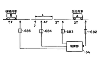
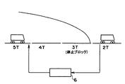
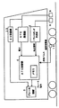
地上装置6は車上に与える情報を生成し、それをデジタル信号としてレールに流すように構成され、図3に示すように、地上制御部6Aと、この地上制御部6Aと各ブロックを個別に接続する通信線と、各通信線に介装された送受信部6Bと、を含んでいる。地上制御部6Aは、ブロックに列車がいるかどうかを前記通信線を介して検知し、列車がいた場合、当該通信線に介装された送受信部6Bに、ブロックへの情報送信を指示する。情報送信を指示された送受信部6Bは、当該ブロックの番号(自ブロック番号)と、地上制御部6Aから伝達された停止ブロック番号を含む信号を、当該ブロックに送信する。
【0027】
以下、上記構成の自動列車制御装置の動作の概要を説明する。
【0028】
地上装置は、ブロックを介して車上装置に自ブロック番号と停止ブロック番号を送信し、車上装置は、受信した停止ブロック番号に基づいてブロック番号ごとに設定された速度パターンをメモリ45から読み出す。車上装置はトランスポンダ地上子7から伝達されるブロック番号とブロック内残距離及び速度発電機10の速度パルスに基づいて自列車位置を常に認識しており、前記読み出した速度パターンにおける自列車位置での速度(許容速度)と、速度発電機10から得られる現在の自列車速度を比較する。車上装置は、速度パターンにおける自列車位置での速度と現在の自列車速度の差に応じて異なる強さのブレーキ指令をブレーキ装置5に出力し、受信した停止ブロック番号のレール区間で停止するように列車速度を制御する。
【0029】
次ぎに、上記動作の詳細について更に説明する。
【0030】
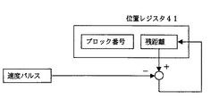
まず、車上装置の位置認識の方法について説明する。トランスポンダ地上子7は,図3に示すように、レールに沿って所々に設置され、そのトランスポンダ地上子が設置されたブロック番号(図3では4T)と、当該ブロックの終端からトランスポンダ地上子7までの距離Lが、トランスポンダ車上子8による読み出しが可能なデータとして地上子内に記憶されている。トランスポンダ車上子8がトランスポンダ地上子7の直上を通過すると、それらの情報がトランスポンダ車上子8に読み込まれる。車上のATC制御部4内には、自列車の位置の記憶、更新のため位置レジスタ41が設けられており、この位置レジスタ41は、ブロック番号と、ブロック内残距離とを格納するようになっている。トランスポンダ車上子8がトランスポンダ地上子7の直上を通過するとき、トランスポンダ車上子8は、トランスポンダ地上子7のデータ(前記ブロック番号4Tと距離L)を読み込む。トランスポンダ車上子8は、読み込んだデータをATC制御部4に送り、ATC制御部4は、ブロック番号と前記距離Lの情報をトランスポンダ車上子8から受けると、図4に示すように、位置レジスタ41内のブロック番号とブロック内残距離を、トランスポンダ車上子8からの情報でセットする。
【0031】
ATC制御部4の検索処理部4Aは、速度発電機10からの速度パルスを取り込み、その速度パルスを積算することによって列車位置を更新できるようになっている。したがってその後、列車が進行すると、検索処理部4Aは、速度発電機から速度パルスを取り込み、この速度パルスを積算することにより、図5に示すように、位置レジスタ41内のブロック内残距離を減算し、位置レジスタ41の内容を更新してゆく。すなわち、自列車の位置は、位置レジスタ41のブロック番号とブロック内残距離に格納されたデータとして、リアルタイムで保持、格納されている。列車が更に進行してゆくと、やがて、位置レジスタ41の残距離が0になる、即ち列車が当該ブロックの終端に達する。
【0032】
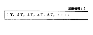
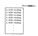
車上のATC制御部4のメモリ45には、ブロック番号の並びを特定できる情報、すなわちブロック接続情報が格納されている。具体的には図6に示すように、ブロック番号の実際の線路での並び方が分かる情報、接続情報42がメモリ45の中に記憶されている。位置レジスタ41のブロック内残距離がゼロになると、検索処理部4Aは、メモリ45の中に記憶されたブロック番号の並びに関する情報から、現在の位置レジスタのブロック番号の次のブロック番号を検索する。またメモリ45の中には図7に示すように、各ブロックの長さに関する情報、すなわちブロック長情報43も記憶されており、検索処理部4Aの論理により、先ほど検索した新しいブロック番号のブロックの長さがこの情報から検索され、新しいブロック番号と、そのブロックの長さが、図8に示すように、位置レジスタ41に新しい位置情報としてセットされる。
【0033】
このようにして、位置レジスタ41は、列車の進行に合わせて常に計算、更新される。もし、この状態で走行中に新たにトランスポンダ地上子7を通過した場合、位置レジスタ41は当該トランスポンダ地上子から得られた情報に書き換えられる。位置レジスタ41のブロック内残距離は、速度パルスにより更新されるため、速度パルスがその速度発電機が結合されている車軸の車輪の空転や滑走などで、誤差を生ずることもあり得るが、その場合、次のトランスポンダ地上子7の情報を受けることにより補正される。
【0034】
上述のようにして、自列車の位置は、常に、走行中のブロック番号と、そのブロック番号で示されるレール区間の末端までの距離(ブロック内残距離)という形で、ATC制御部4に保持されている。
【0035】
次ぎに、地上装置から送信される停止ブロック番号について図3を参照して説明する。地上制御部6Aは、通信線を介して各ブロックに列車がいるかいないかを常時検知しており、あるブロック(図3の例では2T)に列車Aがいる場合(列車が走行しているか、停止しているかに関わりなく)、その後方の列車Bがいるブロックに接続された通信線に介装された送受信部6B5に対して、ブロック番号2Tから所定の距離だけ列車B側に離れたブロックの番号(例えば3T)を送信する。送受信部6B5は、受信したブロック番号3Tを停止ブロック番号とし、自己の属するブロック番号5Tを自ブロック番号として、停止ブロック番号と自ブロック番号のデジタル信号を生成し、特定の周波数で変調(MSK変調)してブロック5Tに出力する。当然、列車Aが存在するブロック2Tに対しても、列車Aの前方にいる列車の位置で決まる停止ブロック番号と自ブロック番号2Tが、ブロック2Tに接続された通信線を介して送受信部6B2から出力される。ブロック5Tに出力された信号は、ATC受電器9によりレールから検出され、ATC受信部3で復調されてATC制御部4に入力される。
【0036】
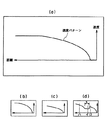
ATC制御部4のメモリ45には、停止ブロック番号として指定されるブロック番号毎に、当該列車が、停止ブロック番号で指定されたブロックのレール区間で停止するための減速状態を規定する速度パターンが記憶されている。速度パターンとは、位置と速度の対の情報であり、指定されたブロックの終端までに列車速度ゼロにするブレーキ曲線である。この速度パターンは停止ブロックとして指定されるブロックとその外方一定距離分の長さに亘って定義されている。一定の長さとは当該列車が最高速度からブレーキを掛けて止まり得る距離に余裕を加えたものであり、例えば、在来の列車の場合は3km程度、高速の幹線の場合は20km程度とする。列車が最高速度からブレーキを掛けて止まり得る距離は列車のブレーキ性能、列車種別、軌道(レール)の傾斜、カーブの程度等により異なる。したがって、この速度パターンの形状は、列車ごとに、かつ停止ブロックごとに設定されている。通常は図11の(a)のような放物線状であるが、もし、当該区間が下り勾配の場合は、同じブレーキ性能を仮定した場合、実効ブレーキ減速度が下り勾配によって低くなってしまうため、この場合の速度パターンは(c)に示すように傾きの低い、言わば「寝た」曲線となる。また、途中に急なカーブなどがある場合は、その区間に速度制限が加わり(d)に示すような形状になることもあり得る。これらの速度パターンはブロック番号ごとにメモリ45に記憶されている。
【0037】
ATC制御部4の検索処理部4Aは、受信した停止ブロック番号に対応する速度パターン、例えば図9に示すような速度パターンをメモリ45から読み出す。検索処理部4Aは、速度パターンを読み出したら、次に自列車の位置即ち位置レジスタ41の内容から、読み出した速度パターンの距離軸上のどこに自列車がいるかを、求める。先に述べたようにメモリ45には、各ブロックの接続情報42と、各ブロックの長さの情報(ブロック長情報43)をも記憶されている。検索処理部4Aは、停止ブロック番号と自ブロック番号の間にある全てのブロック番号を検索する。そしてこれらのブロックの長さを全て検索し、これらの総和を求める。次に位置レジスタ41のブロック内残距離を加える。この値が停止ブロックの終端から、自列車位置までの距離になる。
【0038】
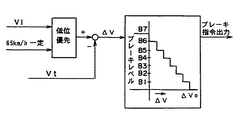
検索処理部4Aは、この距離を読み出した速度パタ−ンの距離軸として速度パターンに割り当て、それに対応する速度を当該速度パターンから求める。ここで得られた速度がその時点(その位置)での列車の許容速度になる。模式的には、図14に示すように、速度パターン上で自列車の位置を決定し、その位置におけるパターン上の速度を許容速度V1として求める。
【0039】
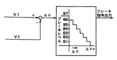
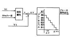
得られた許容速度V1は比較処理部4Cに送られ、速度発電機10から出力された速度パルスに基づいて自列車速度算出部4Bで算出された自列車速度Vtが、許容速度V1から減算される。比較処理部4Cは、自列車速度Vtと許容速度V1の偏差ΔV(=許容速度V1−自列車速度Vt)の値に応じて、図15に示すように、段階的なブレーキ力のブレーキ指令を、ブレーキ装置5に出力する。すなわち、図10に示すように、速度パターンを基準にブレーキの強弱が調整されながら、この速度パターンに沿って減速され、ブロック3Tの終端までに停止するような制御が行われる。
【0040】
図15に示すように、自列車速度Vtが許容速度V1より予め設定された一定値以上低いとき(ΔV≧ΔV0)には、ブレーキ指令は出力されないが、その差が小さくなるにつれ徐々に強いブレーキ指令が出力されるようになっている。自列車速度Vtが速度パターンで規定される許容速度V1を超過すると、常用最大ブレーキB7が出力される。このブレーキ出力の結果により、実速度は速度パターンに沿って減速し、パターンの終端で実列車速度もゼロとなる。自列車速度Vtが許容速度V1より低い場合でもブレーキ指令が出力されるのは、自列車速度Vtが許容速度V1を超過してからブレーキをかけるのでは、速度の超過が大きくなること、自列車速度Vtが許容速度V1を超過してから急に強いブレーキをかけると衝撃が大きく、不快感を与えること、などが理由である。
【0041】
なお、図13に示すように、通常、制御上のマージンを持たせるために、速度パターンの終端は、当該ブロック内残距離「0」の位置ではなく、余裕距離をとり、ブロック内残距離「L0m」の位置に設定している。これにより距離認識の誤差などに対するマージンとしている。
【0042】
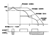
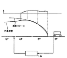
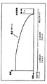
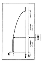
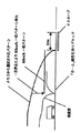
図2に、本実施の形態による列車の減速時の速度パターン(破線)と、従来の段階的な減速パターン(実線)を対比して示す。下部に示したのはブレーキ指令であり、横軸の上側が従来技術の場合、横軸の下側が本発明の場合である。図から明らかなように、従来技術の場合、許容速度がブロック単位で出力されるために許容速度0の信号が早い段階で出されており、このため、ブレーキ指令が2回に分かれ、かつ、早い時期になって、図のア点で減速が開始される。一方、本発明の場合、許容速度0の信号は停止位置であるエ点であり、ブレーキ指令は減速開始から停止まで中断することなく連続して出力されている。
【0043】
この結果、減速期間中の走行距離が短くて済むため、減速開始時期が図のイ点となり、従来技術の場合のア点よりも遅い位置(停止位置に近い点)になる。したがって、減速前の速度V0での走行距離が長くなり、平均運行速度が高くなる。また、列車停止位置も、従来技術の場合のウ点に対し、本発明の場合はエ点となり、先行列車との間隔を短縮できる。
【0044】
一方、このシステムでは、電源が遮断されたら位置レジスタ41のデータはなくなる。したがって、例えば電車が始発駅などで電源投入した直後、あるいは停電などで列車が停止したのち電源が復旧したときは位置未確定であり、トランスポンダ地上子7を通過するまでは自列車位置を確定することが出来ない。電源投入時にたまたまトランスポンダ地上子の直上にいれば別であるが、一般的には、電源投入直後は自列車位置は不定のままである。その状態で走行し、トランスポンダ地上子を通過して初めて自列車位置が認識される。したがって、電源投入時には自列車の位置が車上装置では認識されておらず、上述の方法では許容速度の算出ができない。
【0045】
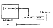
そこで、本発明においては、電源投入時など、位置未確定の際には、次ぎのような手順で仮位置設定を行うこととした。すなわち、位置レジスタ41の「ブロック番号」が図16に示すように地上から送信される「自ブロック番号」に、「ブロック内残距離」が、前記「自ブロック番号」で指定されるブロックのレールの終端から予め設定された距離だけ離れた特定位置に無条件にセットされる。本実施の形態では、残距離「0」の特定位置に無条件にセットされる。設定した位置レジスタの残距離は通常時は、列車の進行に応じて減算されるが、この位置未確定の状態、即ち最初のトランスポンダ地上子の情報を受けてその情報が位置レジスタにセットされるまでは、残距離は列車が進行しても「0」のままとする。最初のトランスポンダ地上子を通過して一旦位置確定したら、位置レジスタは減算を開始することとする。従って、それまでは、自列車位置は、列車が進行しても、地上から送信される「自ブロック番号」で示されるブロックの終端にあるものとして扱う。なお、列車が進行して次ぎのブロックに進入するまで、トランスポンダ地上子を通過しない場合は、位置レジスタ41の「ブロック番号」は、地上から送信される「自ブロック番号」に基づいて更新される。
【0046】
なお、位置レジスタ41の「ブロック内残距離」に設定する残距離、すなわち自列車が位置するブロックの列車進行方向末端からの距離としては、各停止ブロックに対応してメモリ45に格納されている速度パターンの終端の残距離(余裕距離L0m)としてセットするようにしてもよい。
【0047】
ATC制御部4は、速度制御のための速度パターンとしては、通常どおり、地上装置から送信される「停止ブロック番号」で指定されるものを選択する。そしてこれによって検索された速度パターンの距離軸上で、自列車位置が位置レジスタ41の「ブロック番号」で示されるブロックの終端にあるとして決定される速度を許容速度V1として、前記図15に示す論理に基づいてブレーキ指令を出力する。
【0048】
もし、トランスポンダ地上子を通過する前に、地上から伝送される停止ブロックが自ブロックであった場合、自列車位置はちょうどパターン終端にあるから、速度パターンで規定される速度は「0」であり、ブレーキが指令された状態となる。残距離が前記余裕距離「L0m」に設定された場合でも、速度パターンから算出される速度は「0」であって、ブレーキが指令された状態となり、列車は進行できない。しかし、進路が開通するか先行列車が進んで、停止ブロックが内方(列車進行方向前方)に移動した場合は、この仮設定した自列車位置すなわち位置レジスタ41に格納された位置により、通常と同様、パターン検索、パターン参照によって、列車制御が行われる。
【0049】
なお、この位置レジスタ41に設定された位置はあくまで仮位置であるから、一定距離走行する内にトランスポンダ地上子を通過して位置確定しない場合は、位置レジスタのデータを消去し、再度自列車位置未確定にし、非常ブレーキを指令するようにするのが望ましい。この場合は一旦停止後、前記電源投入時の手順が繰り返されるようにすればよい。
【0050】
上述の論理にしたがって制御を行うことにより、自列車の位置が未確定であっても、列車運行の安全が確保され、制御を円滑に行うことができる。自列車位置が確定している場合に比べれば、速度は制限を受けるものの、最初のトランスポンダ地上子まで走行し、トランスポンダ地上子を通過して位置が確定すれば、平常の制御に遷移させることができる。なお、次のトランスポンダを受けるまでに別のブロックに入った場合には、地上からの受信する「自ブロック番号」が変わるため、前述と同様な方式によって自列車位置を与え、同様な制御を継続する。
【0051】
上述のように、列車は、当該列車のブレーキ性能を十分に生かした減速度パターンで、軌動回路の区切りと無関係に減速されるから、減速開始後列車停止までブレーキが解除されることがなく、減速走行する距離が短縮される。言い換えると、停止のためのブレ―キングの開始が遅くてすみ、列車の運行平均速度が高まる。また、先行列車との間隔も詰めることができ、運転効率の向上、乗り心地の向上に寄与することができるとともに、自列車の位置が未確定であっても、列車運行の安全が確保され、制御を円滑に行うことができる。
【0052】
ところで、速度発電機の特性として、数km/h以下の低速では速度パルスが出力されない可能性がある。したがって、極低速で列車が進行した場合、実際に列車は動いていても、ATC制御部4には速度パルスが送られてこないため、列車の進行を検出できず、位置レジスタ41が更新されないということが起こり得る。これでは、速度パターンの距離軸が変化しないため、危険な動作となる恐れがある。
【0053】
したがって、自ブロックが停止ブロックと同一であり、かつ速度が10km/h以下になると自動的にブレーキ指令を出力する論理をATC制御部4に設け、速度パルスが出力されないような極低速で列車が移動することのないようにしてある。このブレーキは先行列車の進行などにより停止ブロックが変化し、停止ブロックが自ブロックと一致しなくなった場合に緩解させる。
【0054】
しかし、特定のブロック、例えば駅のプラットホームに沿うブロックが停止ブロックである場合、前述のように、列車速度10km/h以下でブレーキを指令がかかる構成では、一旦停止すると、停止ブロックが変化しない限り、自動的にブレーキが掛り放しになってしまう。駅中間の本線上であればどこに止まろうと不便は無いが、ホームのあるブロックにあっては、時として停止位置の調整など小移動を行う場合があり、このままでは、停止位置の調整ができなくなる。
【0055】
本実施の形態は、このような事態に対処できるような構成を備えており、これを、図18〜図21を参照して説明する。この構成の特徴は次ぎの3点である。
【0056】
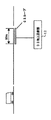
第1点は、図18に示すように、駅ホームなど特定のブロックにおいては、ブロックの終端に50m程度の長さの03ループと称するループが敷設され、03ループに信号を送信する03地上送信器12が接続されている点である。このループは当該ブロックが停止ブロックであるときは、即時停止すべき信号を車上に発信している。
【0057】
第2点は、図19に示すように、ATC受電器9の出力側に接続して03受信部13が設けられ、03受信部13の出力側が、ブレーキ装置5に接続されている点である。この03受信部13は、03ループの停止信号を受信すると無条件でブレーキ指令をブレーキ装置5に出力するようになっている。なお、図19に示す構成は、一部図示が省略されているが、03受信部13が設けられている以外は前記図1と同じである。
【0058】
第3点は、車上のメモリ45にブロックごとにその属性を持たせる構造としておき、自ブロックが「ホーム」である場合に、「ホーム」である旨の属性を持たせておき、自ブロックが停止ブロックであるとき、自ブロックの属性が「ホーム」であれば、前記ATC制御部4は、列車速度が10km/h以下であってもブレーキを出力しないように構成されている点である。
【0059】
すなわち、本実施の形態では、駅ホームなど特定のブロックにおいては、これまでに説明した地上装置に追加して、ブロックの終端に50m程度の長さの03ループと称するループが敷設され、この03ループに信号を送信する03地上送信器12が接続されている。このループは当該ブロックが停止ブロックであるときは、即時停止すべき信号を車上に発信している。また、図19に示すように、これまで説明した車上装置に追加して、ATC受電器9の出力側に接続して03受信部13が設けられ、ATC受電器9は、前記03ループに出力される信号をも読み出せるようになっている。そして、03受信部13の出力側が、ブレーキ装置5に接続されていて、03ループの停止信号を受信すると無条件でブレーキ指令をブレーキ装置5に出力するようになっている。さらに、メモリ45はブロックごとにその属性を格納する構造となっており、自ブロックが「ホーム」である場合に、「ホーム」である旨の属性を持たせてある。
【0060】
前記ATC制御部4は、自ブロックが停止ブロックと一致しても、自ブロックが「ホーム」という属性であった場合、列車速度が10km/h以下であってもブレーキを出力しないようにしてある。これにより、列車はホームで停止してもブレーキが作用し放しになることはなく、小移動も可能である。但し、この場合、先に述べたように極低速で走行した場合、実際の列車は進んでいるにもかかわらず位置レジスタが変化せず、ブレーキを掛けるべき位置になっても、速度パターンの距離軸にズレが生じ、ブレーキが出力されないという可能性がある。そのため、属性が「ホーム」であるブロックで列車が停止した場合は、ATC制御部4は、メモリ45から選択される速度パターンにおける停止位置での列車速度V1に対し、予め設定した一定速度(例えば30km/h)を上限速度としてブレーキ制御を行うようにしてある。
【0061】
図21にこの場合のブレーキ出力論理を、また動作制御の概要を図20に、それぞれ示す。ここで、予め設定した一定速度(例えば30km/h)というのは、列車が03ループに進入した場合に直ちにブレーキが動作し、ループ内で停止し得る速度である。万一、低速走行が連続して位置レジスタが更新されず、速度パターンによる制御による安全が確保できなくなった場合にも、この03ループにより強制的にブレーキが出力されれば、当該ブロック終端までには停止させることが可能である。
【0062】
本実施の形態によれば、ホームでの小移動を可能にしつつ、同時に列車を確実にブロック終端までに停止させることが可能である。
【0063】
次ぎに図17を参照して本発明の第2の実施の形態を説明する。本実施の形態が前記第1の実施に形態と相違するのは、比較処理部4Cが、図17に示すように、速度パターンから算出された許容速度V1と予め設定された最低の速度制限値(例えば65km/h)のうちの低い方の速度を許容速度としてブレーキ指令を出力するように構成されている点である。他の構成は前期第1の実施の形態と同じであり、詳細な説明は省略する。
【0064】
このブレーキ指令出力の論理を図17に示す。ここで、前記予め定められた一定の速度(例示した65km/h)というのは、車上装置のメモリ45に記憶されている本来の速度パターンに含まれる最低の速度制限値であるが、列車停止のための減速曲線で規定される速度ではなく、レールのカーブや分岐の存在など、レールの条件で規定される速度制限値である。例えば、図11の(d)の領域Sは、レールのカーブがきついために、低い速度に制限されている。列車が図11の(d)のイ点にいて停電し、停電復旧後、電源を入れたとする。前記第1の実施の形態の論理に基づき、位置レジスタに設定される位置が実際のブロックの末端ロ点に設定され、その時点での停止ブロックに基づく速度カーブが図11の(d)のような形状であると、列車が実際は図11の(d)のイ点にいるのに、ブロックの末端(ロ点)にいるとして速度パターンから速度を算出される。この場合、算出された速度は実際の位置(イ点)に対応する速度(速度制限値)よりも高い速度となる。本実施の形態では、位置レジスタに設定されたロ点に対応する速度と速度制限値(領域Sに対応する速度)のうち、低速側の速度(領域Sに対応する速度)を選択することにより、実際の位置に対応した安全側の制御となる。
【0065】
一方、実際は列車が許容速度が高いハ点にいるのに、前記論理により、低い速度制限値に対応した速度になるようブレーキ指令が出力される場合がある。しかしこの場合も、列車位置が確認されていない状態で、安全側の速度で列車の運行を継続できる効果がある。
【0066】
なお、上記各実施の形態においては、全てブロックを単位として説明した。しかし、実際の列車制御においては、ブロックを複数個まとめた「閉塞区間」を設定し、一つの閉塞区間には一つの列車しか存在しないように制御する場合がある。このような場合には、前記「ブロック」、「ブロック番号」を、「閉塞区間」、「閉塞区間番号」に置き換え、「閉塞区間」単位で制御行うことにより、同様に本発明は適用可能であり、また同様な効果が期待できる。
【0067】
【発明の効果】
本発明によれば、列車の平均運行速度を高めることができ、列車の運転効率を向上させるとともに、電源投入直後などのトランスポンダ地上子による列車位置確認ができない場合でも、円滑に列車を制御することが可能である。また、駅のプラットホームに沿うレール区間など、予め指定されたブロックでは、当該ブロックが停止ブロックの場合であっても、列車が一旦停止しても、低速で移動することが可能であり、停止位置の修正が容易である。
【図面の簡単な説明】
【図1】本発明の第1の実施の形態の全体構成を示すブロック図である。
【図2】従来技術の場合の列車速度の変化と図1に示す実施の形態の列車速度の変化を対比して示す概念図である。
【図3】図1に示す実施の形態の地上装置の配置例を示す概念図である。
【図4】図1に示す実施の形態のトランスポンダ地上子のデータと位置レジスタのデータの関連を示す図である。
【図5】図1に示す実施の形態の速度パルスのデータと位置レジスタのデータの関連を示す図である。
【図6】図1に示す実施の形態の接続情報の例を示す図である。
【図7】図1に示す実施の形態のブロック長情報の例を示す図である。
【図8】図1に示す実施の形態の車上のメモリに格納されたデータと位置レジスタのデータの更新時の関連を示す図である。
【図9】図1に示す実施の形態の停止ブロックと速度パターンの対応を説明する概念図である。
【図10】図1に示す実施の形態の速度パターンとブレーキ指令の関連の例を示す概念図である。
【図11】図1に示す実施の形態の速度パターンの例を示す図である。
【図12】図1に示す実施の形態のATC制御部の構成例を示すブロック図である。
【図13】図1に示す実施の形態の速度パターンと起動回路の位置の関係の例を示す概念図である。
【図14】図13に示す速度パターンに基づいて許容速度の検索を行う方法を説明する概念図である。
【図15】図1に示す実施の形態のブレーキ出力の選択論理を示す概念図である。
【図16】図1に示す実施の形態における電源投入時の位置レジスタの設定方法を示す概念図である。
【図17】本発明の第2の実施の形態におけるブレーキ指令出力の論理を説明する概念図である。
【図18】本発明の第1の実施の形態の構成の部分を示す概念図である。
【図19】本発明の第1の実施の形態における車上装置の構成を示すブロック図である。
【図20】本発明の第1の実施の形態における駅のホームにおける速度制御の論理を説明する概念図である。
【図21】本発明の第1の実施の形態におけるブレーキ指令出力の論理を説明する概念図である。
【符号の説明】
1 レール
2 トランスポンダ受信部
3 ATC受信部
4 ATC制御部
4A 検索処理部
4B 自列車速度算出部
4C 比較処理部
5 ブレーキ装置
6 地上装置
6A 制御部
6B2〜6B5 送受信部
7 トランスポンダ地上子
8 トランスポンダ車上子
9 ATC受電器
10 速度発電機
12 03地上送信器
13 03受信部
41 位置レジスタ
42 接続情報
43 ブロック長情報
45 メモリ[0001]
[Technical field to which the invention belongs]
The present invention relates to an automatic train control device, and more particularly, to an on-board automatic train control device that performs speed control mainly by the train side when performing speed control for decelerating the train, such as when there is a preceding train.
[0002]
[Prior art]
In a conventional automatic train control device for rail vehicles (hereinafter referred to as an ATC device), a rail is electrically divided for each length of a rail to form a block, and a ground device is connected to the train for each block. To send a signal indicating the allowable speed. An on-board device is installed on each train, and the on-board device receives a signal indicating the allowable speed via a block, and compares the received allowable speed with the own train speed. When the own train speed exceeds the allowable speed, the on-board device automatically gives a brake command to the brake device and automatically controls the train speed within the allowable speed. If another train (preceding train) is running (or stopped) in front of the traveling direction of the train on which the train is running, the ground device will be followed by the train that is running behind (continuing train). As the train approaches the running (or stopped) block (the in-line block), a low permissible speed signal is given to the continuing train.
[0003]
The permissible speed indicated by the ground equipment does not change in the same block, so that the continuation train is subject to a stepwise speed limit in units of blocks, so that it does not collide with the preceding train (the block in front of the preceding train (or the closed section of the rail) ) Controlled to stop on the rail.
[0004]
[Problems to be solved by the invention]
In consideration of increasing the operation efficiency, that is, increasing the number of trains and the average speed of the train, it is desirable that the distance between the preceding train and the continuation train be as short as possible to ensure safety.
[0005]
In the above conventional control method, the permissible speed is a control that changes stepwise, so if the train enters a block where the permissible speed is lower than before, at the beginning of the rail section constituting that block, A lower permissible speed is received and the brake is activated immediately. Therefore, the train speed drops below the allowable speed before the train reaches the end of the rail section constituting the block, and the brake that has been actuated is once released.
[0006]
In other words, from the viewpoint of reducing the distance from the preceding train, the conventional method described above is that the brake is operated earlier than necessary. Further, since the permissible speed is changed stepwise, the brake operation and the release are repeated many times as many as the number of steps, which has an adverse effect on riding comfort.
[0007]
In addition, when multiple types of trains with different brake performances travel, the ground device is not designed to recognize the brake performance of each train, so the allowable speed indicated by the ground device is the most Even for trains with low braking performance, consideration is given to maintaining safety. That is, the allowable speed is determined based on the brake distance of a train having a low brake performance, and the allowable speed is uniformly designated for all trains regardless of the level of the brake performance. For this reason, trains with high braking performance also have a waste in driving efficiency, which is a way of traveling according to trains with low braking performance.
[0008]
The object of the present invention is to improve the operation efficiency of the following train even when the operation of the following train is restricted by the presence of the preceding train. At the same time, if the block along the platform of the station is to be stopped, consider driving safety and improve driving efficiency. There is.
[0009]
[Means for Solving the Problems]
In order to achieve the above object, the ground device has a function to provide information indicating where to stop with respect to the train via the rail, and the on-vehicle device has a position specified by this information. In order to stop at the same time, it is necessary to determine what speed it is necessary to travel based on the position of the own train and to apply the brakes as necessary. When the position cannot be confirmed, the on-board device may tentatively set the position of the own train.
[0010]
That is, the ground device transmits a block number (stop block number) that the train should stop to the on-vehicle device via the block, and the block number to which the stop block number is transmitted is combined with the stop block number. It is transmitted to the on-board device as its own block number. The on-board device holds the position information read from the transponder ground unit in the position information memory, and updates the data in the position information memory based on the speed pulse output from the speed generator according to the rotation of the axle. Always recognize where your train is running. While the position information read from the transponder ground unit is not stored in the position information memory, the train is assumed to be located in the block specified by its own block number transmitted from the ground device, and the train traveling direction of that block A position away from the end by a predetermined distance is recognized as a train position. This position is not updated as the train progresses. The on-board device also has a preset speed pattern for each train and for each block (decelerate from the maximum speed of the train on the premise that the brake performance of the train is fully demonstrated) A position indicating the deceleration process to be stopped—allowable speed pattern) is stored in the memory as a database, and a speed pattern corresponding to the stop block number received from the ground device is read. The on-board device compares the own train speed with the allowable speed determined from the recognized speed pattern and the recognized own train position, and outputs a brake command according to the deviation between the allowable speed and the own train speed to output the train speed. To stop the train in the block to be stopped.
[0011]
By the way, as a characteristic of the speed generator, speed pulses may not be output at a low speed of several km / h or less. Therefore, when the train travels at an extremely low speed, even if the train is actually moving, a speed pulse is not output, so that the progress of the train cannot be detected and the data in the position information memory may not be updated. In this case, since the position (distance axis) on the speed pattern does not change, there is a risk of dangerous operation.
[0012]
Therefore, when the own block is the same as the stop block and the speed becomes 10 km / h or less, the brake command is automatically output, and the train does not move at an extremely low speed so that the speed pulse is not output. Like that. This brake is released when the stop block changes due to the progress of the preceding train and the stop block does not coincide with the own block.
[0013]
However, in this way, if the train stops at a specific block, for example, a block along the platform of the station, the automatic braking command is applied even if the train is moved to correct the stop position. Therefore, it cannot be moved.
[0014]
The present invention can cope with such a situation.
[0015]
Specifically, in the present invention that achieves the above-described object, the rails that are electrically divided and constitute the blocks are each assigned information that designates a block to be stopped by the train and a block number to which the information is transmitted. Including a ground device for transmitting a digital signal, a transponder ground element which is arranged at intervals along the rail and stores information indicating the position thereof in a readable manner, and an on-vehicle device disposed on the train A vehicle-based automatic train control device comprising: an ATC receiving unit that receives and outputs a signal sent to the rail; and reads position information stored in the transponder ground unit. A transponder receiving means for outputting at a speed generator, a speed generator coupled to a train axle for transmitting a speed pulse in accordance with the rotation of the axle, and the output of the ATC receiving means And a ATC controller for outputting a brake command based on the speed pulse and the output of the transponder receiver means said speed generator, the ATC controller Is A combination of a speed pattern representing an allowable speed at each position until the train stops at a block which is set in a one-to-one correspondence with each of the plurality of blocks and information identifying the block to be stopped is stored. And the position information memory for storing the position information output by the transponder receiving means, and the position information stored in the position information memory is updated based on the speed pulse to recognize the own train position, Based on the information specifying the block to be stopped received by the ATC receiving means, the speed pattern corresponding to the block is read from the memory, and the allowable speed at the position is determined based on the read speed pattern and the own train position. And outputs a brake command corresponding to the deviation between the calculated allowable speed and the own train speed, and the position information memory When the position information output by the transponder receiving means is not stored, the block specified by the block number transmitted from the ground device is set as the block of the own train position, and is separated from the end of the block by a preset distance. In the on-vehicle automatic train control device that recognizes the specific position as the own train position, the ATC control unit is configured not to update the specific position until the position information of the transponder receiving means is received, and When the own block where the own train is located coincides with the block to be stopped, the speed pulse is not output. Block where the block including the rail section along the platform of the station should stop In this case, the brake command should not be output even if the speed is lower than the low speed, and When the train stops on the block, the own train is controlled at the speed of the speed pattern read from the memory, and brake control is performed with a predetermined constant speed as an upper limit.
[0018]
By applying the above-mentioned means, the train will show a deceleration speed pattern suitable for each brake performance, so that the brake will not operate intermittently, but will operate continuously until the train stops. Become. Therefore, the time when the brake operation is started is shifted later, the period during which the brake is not operated becomes longer, and the average operation speed is improved. An increase in average operation speed means improved driving efficiency. In order to actually apply the present invention, it is necessary to consider the correction of the stop position when the train stops at a block along the platform of the station. It is configured to calculate a deviation from the own train speed using a predetermined constant speed, for example, the lower speed of 30 km / h as an allowable speed, and even if the train stops, it can move at a low speed As a result, the stop position can be corrected.
[0019]
DETAILED DESCRIPTION OF THE INVENTION
Hereinafter, a first embodiment of the present invention will be described with reference to the drawings.
[0020]
FIG. 1 shows a main configuration of the present embodiment. The illustrated embodiment includes a ground device, an on-vehicle device, a transponder ground element (hereinafter referred to as a transponder ground element) 7 and a block.
[0021]
The on-board device includes an
[0022]
As shown in FIG. 12, the
[0023]
The
[0024]
The
[0025]
The transponder ground element 7 is arranged along the rail at an interval, and the block corresponding to the block number where the transponder ground element 7 is disposed and the position where the transponder ground element 7 is disposed constitutes the block there. The distance to the end of the rail section (the remaining distance in the block) is stored as data. This data is transmitted to the transponder vehicle upper element 8 passing near the transponder ground element 7 as the train progresses.
[0026]
The
[0027]
The outline of the operation of the automatic train control device having the above configuration will be described below.
[0028]
The ground device transmits its own block number and stop block number to the on-vehicle device via the block, and the on-vehicle device reads the speed pattern set for each block number from the
[0029]
Next, details of the above operation will be further described.
[0030]
First, a method for recognizing the position of the on-board device will be described. As shown in FIG. 3, the transponder ground element 7 is installed in places along the rail, the block number (4T in FIG. 3) where the transponder ground element is installed, and the end of the block to the transponder ground element 7 Is stored in the ground unit as data that can be read out by the transponder vehicle upper unit 8. When the transponder vehicle upper part 8 passes immediately above the transponder ground element 7, such information is read into the transponder vehicle upper element 8. In the
[0031]
The search processing unit 4A of the
[0032]
The
[0033]
In this way, the position register 41 is always calculated and updated as the train progresses. If the transponder ground element 7 is newly passed while traveling in this state, the position register 41 is rewritten with information obtained from the transponder ground element. Since the remaining distance in the block of the position register 41 is updated by the speed pulse, the speed pulse may cause an error due to idling or sliding of the wheel of the axle to which the speed generator is coupled. In this case, the information is corrected by receiving the information of the next transponder ground element 7.
[0034]
As described above, the position of the own train is always held in the
[0035]
Next, stop block numbers transmitted from the ground device will be described with reference to FIG. The
[0036]
In the
[0037]
The search processing unit 4A of the
[0038]
The search processing unit 4A assigns this distance to the speed pattern as the distance axis of the read speed pattern, and obtains the corresponding speed from the speed pattern. The speed obtained here becomes the allowable speed of the train at that time (the position). Typically, as shown in FIG. 14, the position of the own train is determined on the speed pattern, and the speed on the pattern at the position is obtained as the allowable speed V1.
[0039]
The obtained allowable speed V1 is sent to the comparison processing unit 4C, and the own train speed Vt calculated by the own train speed calculation unit 4B based on the speed pulse output from the
[0040]
As shown in FIG. 15, when the own train speed Vt is lower than the allowable speed V1 by a predetermined value or more (ΔV ≧ ΔV 0 ), No brake command is output, but as the difference becomes smaller, a stronger brake command is output. When the own train speed Vt exceeds the allowable speed V1 defined by the speed pattern, the service maximum brake B7 is output. As a result of this brake output, the actual speed decelerates along the speed pattern, and the actual train speed also becomes zero at the end of the pattern. Even when the own train speed Vt is lower than the allowable speed V1, the brake command is output because if the brake is applied after the own train speed Vt exceeds the allowable speed V1, the excess of the speed becomes large. This is because, if the brake is suddenly applied after the speed Vt exceeds the allowable speed V1, the impact is large and uncomfortable.
[0041]
As shown in FIG. 13, normally, in order to provide a margin for control, the end of the speed pattern is not the position of the remaining distance “0” in the block, but a margin distance, and the remaining distance “in block” “ L 0 "m" position. This provides a margin for errors such as distance recognition.
[0042]
In FIG. 2, the speed pattern (dashed line) at the time of deceleration of the train according to the present embodiment and a conventional stepwise deceleration pattern (solid line) are shown in comparison. Shown at the bottom is a brake command, where the upper side of the horizontal axis is the prior art, and the lower side of the horizontal axis is the case of the present invention. As is clear from the figure, in the case of the prior art, since the allowable speed is output in units of blocks, the signal of the allowable speed 0 is output at an early stage, and therefore, the brake command is divided into two times, and At an early time, deceleration starts at point a in the figure. On the other hand, in the case of the present invention, the signal of the allowable speed 0 is the point D that is the stop position, and the brake command is continuously output without interruption from the start of deceleration to the stop.
[0043]
As a result, since the travel distance during the deceleration period can be shortened, the deceleration start timing becomes point a in the figure, and the position is later than the point a in the prior art (a point closer to the stop position). Therefore, the speed V before deceleration V 0 The driving distance in the city will be longer and the average operation speed will be higher. Further, the train stop position is a point D in the case of the present invention with respect to the point C in the case of the prior art, and the distance from the preceding train can be shortened.
[0044]
On the other hand, in this system, when the power is cut off, the data in the position register 41 is lost. Therefore, for example, immediately after the power is turned on at the first train station or when the power is restored after the train stops due to a power failure or the like, the position is uncertain, and the position of the own train is determined until it passes the transponder ground element 7 I can't. It is different if it happens to be directly above the transponder ground at the time of power-on, but in general, the position of the own train remains indeterminate immediately after power-on. The train position is recognized only after traveling in this state and passing through the transponder ground element. Therefore, the position of the own train is not recognized by the on-board device when the power is turned on, and the allowable speed cannot be calculated by the above-described method.
[0045]
Therefore, in the present invention, when the position is uncertain, such as when the power is turned on, the temporary position is set according to the following procedure. That is, as shown in FIG. 16, the “block number” in the position register 41 is the “own block number” transmitted from the ground, and the “in-block remaining distance” is the rail of the block specified by the “own block number”. It is unconditionally set at a specific position that is a predetermined distance away from the end of. In the present embodiment, it is set unconditionally at a specific position of the remaining distance “0”. The remaining distance of the set position register is normally subtracted according to the progress of the train, but this position is indeterminate, that is, the information of the first transponder ground element is received and the information is set in the position register. Until then, the remaining distance remains “0” even if the train travels. Once the position is determined after passing the first transponder ground element, the position register starts subtraction. Therefore, until then, the own train position is treated as being at the end of the block indicated by the “own block number” transmitted from the ground even if the train travels. When the train does not pass through the transponder ground unit until the train advances and enters the next block, the “block number” in the position register 41 is updated based on the “own block number” transmitted from the ground. .
[0046]
The remaining distance set in the “remaining distance in block” of the position register 41, that is, the distance from the end of the block where the own train is located in the train traveling direction is stored in the
[0047]
The
[0048]
If the stop block transmitted from the ground is the own block before passing through the transponder ground unit, the speed specified by the speed pattern is “0” because the own train position is just at the end of the pattern. The brake is commanded. The remaining distance is the margin distance “L” 0 Even when “m” is set, the speed calculated from the speed pattern is “0”, the brake is commanded, and the train cannot proceed. However, when the route is opened or the preceding train advances and the stop block moves inward (forward in the train traveling direction), the temporary train position, that is, the position stored in the position register 41, Similarly, train control is performed by pattern search and pattern reference.
[0049]
Since the position set in the position register 41 is only a temporary position, if the position is not determined by passing through the transponder ground while traveling a certain distance, the data in the position register is deleted and the own train position is again It is desirable to make it uncertain and to command emergency braking. In this case, the procedure at the time of turning on the power may be repeated after stopping.
[0050]
By performing the control according to the above logic, even if the position of the own train is uncertain, the safety of the train operation is ensured and the control can be performed smoothly. Compared to the case where the own train position is fixed, the speed is limited, but it travels to the first transponder ground element, and if it passes through the transponder ground element and the position is fixed, it can shift to normal control. it can. If you enter another block before receiving the next transponder, the “own block number” received from the ground changes, so give your own train position in the same way as described above and continue the same control. To do.
[0051]
As mentioned above, a train is a deceleration pattern that fully utilizes the braking performance of the train, and is decelerated regardless of the break of the trajectory circuit, so that the brake is not released until the train stops after starting deceleration. The traveling distance for deceleration is shortened. In other words, the start of breaking for stopping is delayed and the average train speed is increased. In addition, the distance from the preceding train can be shortened, which can contribute to improvement of driving efficiency and ride comfort, and even if the position of the own train is uncertain, the safety of train operation is ensured, Control can be performed smoothly.
[0052]
By the way, as a characteristic of the speed generator, speed pulses may not be output at a low speed of several km / h or less. Therefore, when the train travels at a very low speed, even if the train is actually moving, the speed pulse is not sent to the
[0053]
Therefore, the
[0054]
However, when a specific block, for example, a block along a station platform is a stop block, as described above, in a configuration in which a brake is commanded at a train speed of 10 km / h or less, once the stop block is stopped, the stop block does not change. The brakes are automatically released. There is no inconvenience no matter where you stop on the main line in the middle of the station, but there are times when a small movement such as adjustment of the stop position is performed in the block where the platform is, and it is impossible to adjust the stop position as it is .
[0055]
The present embodiment has a configuration capable of coping with such a situation, which will be described with reference to FIGS. The features of this configuration are the following three points.
[0056]
First, as shown in FIG. 18, in a specific block such as a station platform, a loop called a 03 loop having a length of about 50 m is laid at the end of the block, and a signal is transmitted to the 03 loop. The point is that the device 12 is connected. When this block is a stop block, this loop transmits a signal to be stopped immediately on the vehicle.
[0057]
As shown in FIG. 19, the second point is that the 03 receiving
[0058]
The third point is that the
[0059]
That is, in this embodiment, in a specific block such as a station platform, in addition to the above-described ground device, a loop called a 03 loop having a length of about 50 m is laid at the end of the block. A 03 ground transmitter 12 for transmitting a signal to the loop is connected. When this block is a stop block, this loop transmits a signal to be stopped immediately on the vehicle. Further, as shown in FIG. 19, in addition to the on-board device described so far, a 03 receiving
[0060]
The
[0061]
FIG. 21 shows the brake output logic in this case, and FIG. 20 shows an outline of the operation control. Here, the preset constant speed (for example, 30 km / h) is a speed at which the brake is immediately operated when the train enters the 03 loop and can stop within the loop. In the unlikely event that the position register is not updated continuously due to low-speed running and safety cannot be ensured by the control by the speed pattern, if the brake is forcibly output by this 03 loop, the end of the block will be reached. Can be stopped.
[0062]
According to the present embodiment, it is possible to stop the train by the end of the block reliably while enabling a small movement at the home.
[0063]
Next, a second embodiment of the present invention will be described with reference to FIG. This embodiment differs from the first embodiment in that the comparison processing unit 4C, as shown in FIG. 17, has an allowable speed V1 calculated from the speed pattern and a preset minimum speed limit value. The brake command is output with the lower speed (for example, 65 km / h) as the allowable speed. Other configurations are the same as those of the first embodiment, and detailed description thereof is omitted.
[0064]
The logic of this brake command output is shown in FIG. Here, the predetermined constant speed (exemplified 65 km / h) is the minimum speed limit value included in the original speed pattern stored in the
[0065]
On the other hand, although the train is actually at a point where the allowable speed is high, a brake command may be output so as to achieve a speed corresponding to a low speed limit value by the logic. However, in this case as well, there is an effect that the train operation can be continued at a safe speed in a state where the train position is not confirmed.
[0066]
In each of the above embodiments, the description has been made in units of blocks. However, in actual train control, there is a case where a “blocked section” in which a plurality of blocks are collected is set so that only one train exists in one blocked section. In such a case, the present invention can be similarly applied by replacing “block” and “block number” with “blocking section” and “blocking section number” and performing control in units of “blocking section”. Yes, and similar effects can be expected.
[0067]
【The invention's effect】
According to the present invention, the average operation speed of the train can be increased, the operation efficiency of the train can be improved, and the train can be smoothly controlled even when the train position cannot be confirmed by the transponder ground element immediately after the power is turned on. Is possible. In addition, a block designated in advance, such as a rail section along the platform of a station, can move at a low speed even if the block is a stop block, or even if the train stops temporarily. Is easy to correct.
[Brief description of the drawings]
FIG. 1 is a block diagram showing an overall configuration of a first embodiment of the present invention.
FIG. 2 is a conceptual diagram showing a comparison between a change in train speed in the case of the prior art and a change in train speed in the embodiment shown in FIG. 1;
FIG. 3 is a conceptual diagram showing an example of arrangement of the ground device of the embodiment shown in FIG. 1;
4 is a diagram showing the relationship between the data in the transponder ground element and the data in the position register in the embodiment shown in FIG. 1; FIG.
5 is a diagram showing the relationship between velocity pulse data and position register data in the embodiment shown in FIG. 1; FIG.
6 is a diagram illustrating an example of connection information according to the embodiment illustrated in FIG. 1;
7 is a diagram illustrating an example of block length information according to the embodiment illustrated in FIG. 1;
FIG. 8 is a diagram showing a relationship at the time of updating data stored in the on-vehicle memory and position register data according to the embodiment shown in FIG. 1;
FIG. 9 is a conceptual diagram for explaining the correspondence between the stop block and the speed pattern in the embodiment shown in FIG. 1;
10 is a conceptual diagram showing an example of a relationship between a speed pattern and a brake command in the embodiment shown in FIG.
FIG. 11 is a diagram showing an example of a speed pattern of the embodiment shown in FIG. 1;
12 is a block diagram illustrating a configuration example of an ATC control unit according to the embodiment illustrated in FIG. 1;
13 is a conceptual diagram showing an example of the relationship between the speed pattern and the position of the activation circuit in the embodiment shown in FIG. 1;
14 is a conceptual diagram illustrating a method for searching for an allowable speed based on the speed pattern shown in FIG.
15 is a conceptual diagram showing brake output selection logic in the embodiment shown in FIG. 1; FIG.
16 is a conceptual diagram showing a method for setting a position register at power-on in the embodiment shown in FIG.
FIG. 17 is a conceptual diagram illustrating the logic of a brake command output in the second embodiment of the invention.
FIG. 18 is a conceptual diagram showing a portion of the configuration of the first exemplary embodiment of the present invention.
FIG. 19 is a block diagram showing a configuration of the on-board device in the first embodiment of the present invention.
FIG. 20 is a conceptual diagram illustrating the logic of speed control at the station platform according to the first embodiment of the present invention.
FIG. 21 is a conceptual diagram illustrating the logic of a brake command output in the first embodiment of the invention.
[Explanation of symbols]
1 rail
2 Transponder receiver
3 ATC receiver
4 ATC control unit
4A Search processing part
4B Own train speed calculator
4C comparison processor
5 Brake device
6 Ground equipment
6A Control unit
6B2-6B5 transceiver
7 Transponder ground child
8 Transponder car upper
9 ATC power receiver
10 speed generator
12 03 Ground transmitter
13 03 Receiver
41 Position register
42 Connection information
43 Block length information
45 memory
Claims (1)
前記車上装置が、前記レールに送出された信号を受信して出力するATC受信手段と、前記トランスポンダ地上子に格納された位置情報を読み込んで出力するトランスポンダ受信手段と、列車の車軸に結合され車軸の回転に応じて速度パルスを発信する速度発電機と、前記ATC受信手段の出力と前記トランスポンダ受信手段の出力と前記速度発電機の速度パルスとに基づいてブレーキ指令を出力するATC制御部とを有し、
前記ATC制御部は、複数のブロックそれぞれに1対1に対応して設定され列車が停止すべきブロックに停止するまでの各位置における許容速度を表す速度パターンと前記停止すべきブロックを特定する情報とを組合せて格納するメモリと、前記トランスポンダ受信手段が出力した位置情報を格納する位置情報メモリとを備え、前記位置情報メモリに格納された位置情報を前記速度パルスに基づいて更新して自列車位置を認識し、前記ATC受信手段が受信した停止すべきブロックを特定する情報に基づいて当該ブロックに対応する速度パターンを前記メモリから読み出し、読み出した速度パターンと前記自列車位置とに基づいてその位置における許容速度を算出し、算出した許容速度と自列車速度との偏差に応じたブレーキ指令を出力し、前記位置情報メモリに前記トランスポンダ受信手段が出力した位置情報が格納されていないとき、前記地上装置から送信されるブロック番号で特定されるブロックを自列車位置のブロックとし、当該ブロックの末端から予め設定された距離だけ離れた特定位置を自列車位置と認識する車上主体型自動列車制御装置において、
前記ATC制御部は、トランスポンダ受信手段の位置情報が受信されるまで前記特定位置を更新しないように構成され、かつ、自列車が在線する自ブロックが停止すべきブロックと一致したとき、前記速度パルスが出力されなくなる予め設定した低速度以下のときにブレーキ指令を出力し、自ブロックが駅のホームに沿うレール区間を含むブロックが停止すべきブロックの場合は、前記低速度以下であってもブレーキ指令を出力しないようにし、かつ該ブロック上で列車が停止した場合は、前記メモリから読み出した速度パターンの速度で自列車を制御するとともに、予め定められた一定速度を上限としてブレーキ制御を行うように構成されていることを特徴とする車上主体型自動列車制御装置。A ground device for transmitting a digital signal including information for designating a block to be stopped by a train and a block number to which the information is transmitted, on rails that are electrically divided and constitute blocks, along the rails A vehicle-based automatic train control device composed of a transponder ground element that is arranged at intervals and stores information indicating its position so that it can be read, and an on-vehicle device arranged on the train,
The on-board device is coupled to an ATC receiving means for receiving and outputting a signal sent to the rail, a transponder receiving means for reading and outputting position information stored in the transponder ground element, and a train axle. A speed generator that transmits a speed pulse according to the rotation of the axle, an ATC control unit that outputs a brake command based on the output of the ATC receiver, the output of the transponder receiver, and the speed pulse of the speed generator; Have
The ATC control unit is set in a one-to-one correspondence with each of a plurality of blocks, and a speed pattern indicating an allowable speed at each position until the train stops at a block to be stopped and information for specifying the block to be stopped And a position information memory for storing the position information output from the transponder receiving means, and updating the position information stored in the position information memory based on the speed pulse Based on the information for recognizing the position and identifying the block to be stopped received by the ATC receiving means, the speed pattern corresponding to the block is read from the memory, and based on the read speed pattern and the own train position Calculate the allowable speed at the position, and output a brake command according to the deviation between the calculated allowable speed and the own train speed, When the position information output from the transponder receiving means is not stored in the position information memory, the block specified by the block number transmitted from the ground device is set as the block of the own train position, and preset from the end of the block In an on-vehicle-oriented automatic train control device that recognizes a specific position separated by a specified distance as its own train position,
The ATC control unit is configured not to update the specific position until the position information of the transponder receiving means is received, and when the own block where the own train is located coincides with the block to be stopped, the speed pulse there outputs a brake command when: low speed set in advance is not outputted, if the self block is the block to be block stop including a rail section along the station platform, even the equal to or less than the low speed brake If the command is not output and the train stops on the block, the own train is controlled at the speed of the speed pattern read from the memory, and the brake control is performed with a predetermined constant speed as the upper limit. An on-vehicle-based automatic train control device characterized by being configured as follows.
Priority Applications (1)
| Application Number | Priority Date | Filing Date | Title |
|---|---|---|---|
| JP2001227730A JP4172007B2 (en) | 2001-07-27 | 2001-07-27 | On-board automatic train control system |
Applications Claiming Priority (1)
| Application Number | Priority Date | Filing Date | Title |
|---|---|---|---|
| JP2001227730A JP4172007B2 (en) | 2001-07-27 | 2001-07-27 | On-board automatic train control system |
Publications (2)
| Publication Number | Publication Date |
|---|---|
| JP2003047112A JP2003047112A (en) | 2003-02-14 |
| JP4172007B2 true JP4172007B2 (en) | 2008-10-29 |
Family
ID=19060348
Family Applications (1)
| Application Number | Title | Priority Date | Filing Date |
|---|---|---|---|
| JP2001227730A Expired - Lifetime JP4172007B2 (en) | 2001-07-27 | 2001-07-27 | On-board automatic train control system |
Country Status (1)
| Country | Link |
|---|---|
| JP (1) | JP4172007B2 (en) |
Families Citing this family (8)
| Publication number | Priority date | Publication date | Assignee | Title |
|---|---|---|---|---|
| JP4757045B2 (en) * | 2006-01-30 | 2011-08-24 | 株式会社京三製作所 | Train control device |
| JP4746531B2 (en) * | 2006-12-13 | 2011-08-10 | 株式会社東芝 | Electric railway system |
| JP4915795B2 (en) * | 2007-01-05 | 2012-04-11 | 日本信号株式会社 | On-vehicle / ground-to-ground information transmission equipment |
| JP5856935B2 (en) * | 2012-09-14 | 2016-02-10 | 株式会社日立製作所 | Train control system |
| JP5849057B2 (en) * | 2013-02-20 | 2016-01-27 | 株式会社日立製作所 | Train security system |
| JP7139169B2 (en) * | 2018-07-05 | 2022-09-20 | 東日本旅客鉄道株式会社 | Automatic train operation system and automatic operation device |
| CN113928369B (en) * | 2021-11-16 | 2024-04-26 | 交控科技股份有限公司 | Method and device for downloading electronic map in split mode |
| CN114426043B (en) * | 2022-01-29 | 2023-06-30 | 北京全路通信信号研究设计院集团有限公司 | Transponder message sending method and system for improving train station internal operation efficiency |
-
2001
- 2001-07-27 JP JP2001227730A patent/JP4172007B2/en not_active Expired - Lifetime
Also Published As
| Publication number | Publication date |
|---|---|
| JP2003047112A (en) | 2003-02-14 |
Similar Documents
| Publication | Publication Date | Title |
|---|---|---|
| JP2005022558A (en) | Automatic train stop system | |
| JP4172007B2 (en) | On-board automatic train control system | |
| JPH10167070A (en) | Train information transmitting method, train speed control method, and train control system | |
| JP3300915B2 (en) | Train control system | |
| JP7219047B2 (en) | Automated train driving system | |
| JP4025954B2 (en) | On-board automatic train control system | |
| JP4025955B2 (en) | On-board automatic train control system | |
| JP3342979B2 (en) | Train security control system | |
| JP4673498B2 (en) | Automatic train stop device and automatic train stop method | |
| JP4197096B2 (en) | Automatic train control device | |
| JP3968628B2 (en) | On-board automatic train control system | |
| JP3392916B2 (en) | Digital transmission type automatic train controller | |
| Matsumoto et al. | The new ATC system with an autonomous speed control with on-board equipment | |
| JP3742073B2 (en) | Automatic train control device | |
| JP3515346B2 (en) | Automatic train control device | |
| JP4551554B2 (en) | Automatic train control device and automatic train control method based on speed control pattern | |
| JP2003040110A (en) | Train-dominated automatic train control device | |
| JP3498974B2 (en) | Dead end line overrun prevention device | |
| JP2003034250A (en) | Train control system | |
| JP3211067B2 (en) | Railway vehicle speed control device | |
| KR100598002B1 (en) | Ats and ats control method to drive train automatically | |
| JP3498975B2 (en) | Automatic departure train automatic stop device | |
| JP3270305B2 (en) | Signal security device in railway security system | |
| JP7336912B2 (en) | Automated train driving system | |
| US20240174275A1 (en) | Train control system |
Legal Events
| Date | Code | Title | Description |
|---|---|---|---|
| A621 | Written request for application examination |
Free format text: JAPANESE INTERMEDIATE CODE: A621 Effective date: 20050811 |
|
| A977 | Report on retrieval |
Free format text: JAPANESE INTERMEDIATE CODE: A971007 Effective date: 20070416 |
|
| A131 | Notification of reasons for refusal |
Free format text: JAPANESE INTERMEDIATE CODE: A131 Effective date: 20070605 |
|
| A521 | Written amendment |
Free format text: JAPANESE INTERMEDIATE CODE: A523 Effective date: 20070806 |
|
| A131 | Notification of reasons for refusal |
Free format text: JAPANESE INTERMEDIATE CODE: A131 Effective date: 20080108 |
|
| A521 | Written amendment |
Free format text: JAPANESE INTERMEDIATE CODE: A523 Effective date: 20080310 |
|
| A131 | Notification of reasons for refusal |
Free format text: JAPANESE INTERMEDIATE CODE: A131 Effective date: 20080415 |
|
| A521 | Written amendment |
Free format text: JAPANESE INTERMEDIATE CODE: A523 Effective date: 20080616 |
|
| TRDD | Decision of grant or rejection written | ||
| A01 | Written decision to grant a patent or to grant a registration (utility model) |
Free format text: JAPANESE INTERMEDIATE CODE: A01 Effective date: 20080708 |
|
| A01 | Written decision to grant a patent or to grant a registration (utility model) |
Free format text: JAPANESE INTERMEDIATE CODE: A01 |
|
| A61 | First payment of annual fees (during grant procedure) |
Free format text: JAPANESE INTERMEDIATE CODE: A61 Effective date: 20080731 |
|
| R150 | Certificate of patent or registration of utility model |
Free format text: JAPANESE INTERMEDIATE CODE: R150 Ref document number: 4172007 Country of ref document: JP Free format text: JAPANESE INTERMEDIATE CODE: R150 |
|
| FPAY | Renewal fee payment (event date is renewal date of database) |
Free format text: PAYMENT UNTIL: 20110822 Year of fee payment: 3 |
|
| FPAY | Renewal fee payment (event date is renewal date of database) |
Free format text: PAYMENT UNTIL: 20120822 Year of fee payment: 4 |
|
| FPAY | Renewal fee payment (event date is renewal date of database) |
Free format text: PAYMENT UNTIL: 20130822 Year of fee payment: 5 |
|
| EXPY | Cancellation because of completion of term |