JP4146048B2 - Honeycomb filter, honeycomb filter assembly, - Google Patents
Honeycomb filter, honeycomb filter assembly, Download PDFInfo
- Publication number
- JP4146048B2 JP4146048B2 JP27840599A JP27840599A JP4146048B2 JP 4146048 B2 JP4146048 B2 JP 4146048B2 JP 27840599 A JP27840599 A JP 27840599A JP 27840599 A JP27840599 A JP 27840599A JP 4146048 B2 JP4146048 B2 JP 4146048B2
- Authority
- JP
- Japan
- Prior art keywords
- honeycomb filter
- silicon carbide
- honeycomb
- exhaust gas
- cell wall
- Prior art date
- Legal status (The legal status is an assumption and is not a legal conclusion. Google has not performed a legal analysis and makes no representation as to the accuracy of the status listed.)
- Expired - Fee Related
Links
Images


Landscapes
- Processes For Solid Components From Exhaust (AREA)
- Filtering Materials (AREA)
Description
【0001】
【発明の属する技術分野】
本発明は、ハニカムフィルタ及びハニカムフィルタ集合体に関するものである。
【0002】
【従来の技術】
自動車の台数は今世紀に入って飛躍的に増加しており、それに比例して自動車の内燃機関から出される排気ガスの量も急激な増加の一途を辿っている。特にディーゼルエンジンの出す排気ガス中に含まれる種々の物質は、汚染を引き起こす原因となるため、現在では世界環境にとって深刻な影響を与えつつある。又、最近では排気ガス中のスス(ディーゼルパティキュレート)が、ときとしてアレルギー障害や精子数の減少を引き起こす原因となるとの研究結果も報告されている。つまり、排気ガス中のディーゼルパティキュレートを除去する対策を講じることが、人類にとって急務の課題であると考えられている。
【0003】
このような事情のもと、多様多種の排気ガス浄化装置が提案されている。一般的な排気ガス浄化装置は、エンジンの排気マニホールドに連結された排気管の途上にケーシングを設け、その中に微細な孔を有するハニカムフィルタを配置した構造を有している。ハニカムフィルタの形成材料としては、耐熱性・機械的強度・捕集効率が高い、化学的に安定している、圧力損失が小さい等の利点があることから、炭化珪素の多孔質焼結体をフィルタ形成材料として用いることが多い。
【0004】
ここで「圧力損失」とは、フィルタ上流側の圧力値から下流側の圧力値を引いたものをいう。排気ガスがフィルタを通過する際に抵抗を受けることが、圧力損失をもたらす最大の要因である。
【0005】
ハニカムフィルタは自身の軸線方向に沿って延びる多数のセルを有している。排気ガスがハニカムフィルタを通り抜ける際、そのセル壁によってディーゼルパティキュレートがトラップされる。従って、ハニカムフィルタ内に捕集されたディーゼルパティキュレートは、ハニカムフィルタ内の温度が所定値(着火温度)に達すると、着火して燃焼する。昨今、粒子径の小さなパティキュレートは肺への定着率が高く健康に対するリスクが高いことが判明している。よって、小さな粒子径のパティキュレートを補足することに対する要求は高くなっている。
【0006】
【発明が解決しようとする課題】
ところが、セル壁を構成する粒子の比表面積が小さいと、ハニカムフィルタが緻密になりすぎてしまい、排気ガスがハニカムフィルタをスムーズに通過しにくくなり、圧力損失が大きくなる。従って、車両の燃費の悪化、運転フィーリングの悪化を招くという問題がある。
【0007】
本発明は上記の課題に鑑みてなされたものであり、その目的は、圧力損失が小さいハニカムフィルタ及びハニカムフィルタ集合体を提供することにある。
【0008】
【課題を解決するための手段】
上記の課題を解決するために、本発明では、複数のセルを、α型炭化珪素焼結体の多孔質体からなるセル壁によって区画し、このセル壁によってパティキュレートを含む流体を浄化するハニカムフィルタにおいて、α型炭化珪素粒子によって構成されている前記セル壁の比表面積が0.3〜1.0m2/gであることを特徴とするハニカムフィルタである。
【0010】
また、本発明では、複数のセルを、α型炭化珪素焼結体の多孔質体からなるセル壁によって区画し、このセル壁によってパティキュレートを含む流体を浄化するハニカムフィルタを構成部材として用い、これらの構成部材の外周面同士をセラミック質シール材層を介して接着することにより、前記各ハニカムフィルタを一体化してなる集合体であって、α型炭化珪素粒子によって構成されている前記セル壁の比表面積が0.3〜1.0m2/gであることを特徴とするハニカムフィルタ集合体を提案する。
【0011】
以下、本発明の「作用」について説明する。本発明によると、セル壁を構成する粒子の比表面積が0.3m2/g以上であるため、圧力損失を小さくすることができる。つまり、比表面積が0.3m2/gよりも小さいと、ハニカムフィルタが緻密になりすぎてしまい、パティキュレートを含む流体がハニカムフィルタをスムーズに通過しにくくなるからである。
【0012】
また、本発明によると、炭化珪素焼結体製のセル壁は耐熱性に優れているため、上記のごとく温度の高くなりやすい箇所に配設されたとしても、セル壁が変質したり焼失したりするようなことはない。従って、長期間にわたって効率のよい流体の浄化を行うことができる。
【0013】
また、本発明によると、多孔質体からなるセル壁は、よりいっそう圧力損失を小さくすることに貢献できるばかりか、パティキュレートの捕集効率を高めることができる。
【0014】
【発明の実施の形態】
以下、本発明を具体化した一実施形態のディーゼルエンジン用の排気ガス浄化装置1を、図面に基づき詳細に説明する。
【0015】
図1に示されるように、この排気ガス浄化装置1は、内燃機関としてのディーゼルエンジン2から排出される排気ガスを浄化するための装置である。ディーゼルエンジン2は、図示しない複数の気筒を備えている。各気筒には、金属材料からなる排気マニホールド3の分岐部4がそれぞれ連結されている。各分岐部4は1本のマニホールド本体5にそれぞれ接続されている。従って、各気筒から排出された排気ガスは一箇所に集中する。
【0016】
排気マニホールド3の下流側には、金属材料からなる第1排気管6及び第2排気管7が配設されている。第1排気管6の上流側端は、マニホールド本体5に連結されている。第1排気管6と第2排気管7との間には、同じく金属材料からなる筒状のケーシング8が配設されている。ケーシング8の上流側端は第1排気管6の下流側端に連結され、ケーシング8の下流側端は第2排気管7の上流側端に連結されている。排気管6,7の途上にケーシング8が配設されていると把握することもできる。そして、この結果、第1排気管6、ケーシング8及び第2排気管7の内部領域が互いに連通し、その中を排気ガスが流れるようになっている。
【0017】
図1に示されるように、ケーシング8はその中央部が排気管6,7よりも大径となるように形成されている。従って、ケーシング8の内部領域は、排気管6,7の内部領域に比べて広くなっている。このケーシング8内には、ハニカムフィルタ9が収容されている。
【0018】
ハニカムフィルタ9の外周面とケーシング8の内周面との間には、断熱材10が配設されている。断熱材10はセラミックファイバを含んで形成されたマット状物であり、その厚みは数mm〜数十mmである。断熱材10は熱膨張性を有していることがよい。ここでいう熱膨張性とは、弾性構造を有するため熱応力を解放する機能があることを指す。その理由は、ハニカムフィルタ9の最外周部から熱が逃げることを防止することにより、再生時のエネルギーロスを最小限に抑えるためである。又、再生時の熱によってセラミックファイバを膨張させることにより、排気ガスの圧力や走行による振動等のもたらすハニカムフィルタ9の位置ずれを防止するためである。
【0019】
本実施形態において用いられるハニカムフィルタ9は、上記のごとくディーゼルパティキュレートを除去するものであるため、一般にディーゼルパティキュレートフィルタ(DPF)と呼ばれる。図2等に示されるように、本実施形態のハニカムフィルタ9は円柱状である。
【0020】
図2,図3,図4に示されるように、本実施形態のハニカムフィルタ9は、いわゆるハニカム構造を備えている。ハニカム構造を採用した理由は、微粒子の捕集量が増加したときでも圧力損失が小さいという利点があるからである。ハニカムフィルタ9には、断面略正方形状をなす複数の通気孔12がその軸線方向に沿って規則的に形成されている。各通気孔12は薄いセル壁13によって互いに仕切られている。セル壁13の外表面には、白金族元素(例えばPt等)やその他の金属元素及びその酸化物等からなる酸化触媒が担持されている。各通気孔12の開口部は、いずれか一方の端面9a,9bの側において封止体14により封止されている。従って、端面9a,9b全体としてみると市松模様状を呈している。その結果、ハニカムフィルタ9には、断面四角形状をした多数のセルが形成されている。多数あるセルのうち、約半数のものは上流側端面9aにおいて開口し、残りのものは下流側端面9bにおいて開口している。
【0021】
セルの密度は120個/inch2(18個/cm2)以上、より具体的には120〜180個/inch2の範囲であることが好ましい。セルの密度が120個未満であると、排気ガスとの接触面積が小さくなるため、ハニカムフィルタ9の浄化性能が低下するからである。
【0022】
セル壁13の厚みは0.46mm以下、より具体的には0.20〜0.46mmの範囲であることが好ましい。セル壁13の厚みが0.46mmを超えると、セルの開口面積が小さくなり、排気ガスとの接触面積が小さくなるため、ハニカムフィルタ9の浄化性能が低下するからである。又、セルの開口面積を確保しつつ、セル壁13の厚みを0.46mmよりも大きくすれば、ハニカムフィルタ9全体の大型化につながるからである。
【0023】
ハニカムフィルタ9の気孔率は30%〜50%、さらには35%〜49%であることが好ましい。気孔率が30%未満であると、ハニカムフィルタ9が緻密になりすぎてしまい、内部に排気ガスを流通させることができなくなるおそれがあるからである。一方、気孔率が50%を越えると、ハニカムフィルタ9中に空隙が多くなりすぎてしまうため、強度的に弱くなりかつ微粒子の捕集効率が低下してしまうおそれがあるからである。
【0024】
多孔質炭化珪素焼結体を選択した場合においてハニカムフィルタ9の熱伝導率は、20W/mK〜75W/mKであることがよく、さらには30W/mK〜70W/mKであることが特によい。熱伝導率が小さすぎると、ハニカムフィルタ9内に温度差が生じやすくなり、クラックをもたらす原因となる大きな熱応力の発生につながってしまう。逆に、熱伝導率を高くしようとすると、製造が困難となり、安定的な材料供給が難しくなる。
【0025】
ハニカムフィルタ9は、セラミック焼結体の一種である多孔質炭化珪素焼結体製である。炭化珪素焼結体を採用した理由は、他のセラミックに比較して、とりわけ強度、耐熱性及び熱伝導性に優れるという利点があるからである。
【0026】
多孔質炭化珪素焼結体に含まれる不純物は、5重量%以下に抑えられていることが望ましい。不純物の量は1重量%以下であることがよく、0.1重量%以下であることが特によい。不純物が5重量%を超えると、炭化珪素結晶粒子の粒界に不純物が偏り、粒界での強度(結晶粒子間の結合強度)が著しく低下し、粒界破断しやすくなるからである。なお、不純物としては、Al、Fe、O、遊離C等がある。
【0027】
又、前記封止体14の形成材料も、ハニカムフィルタ9と同じ多孔質炭化珪素焼結体製となっている。ここでも多孔質炭化珪素焼結体に含まれる不純物は、5重量%以下に抑えられていることが望ましい。不純物が5重量%を超えると、炭化珪素結晶粒子の粒界に不純物が偏り、粒界での強度(結晶粒子間の結合強度)が著しく低下し、粒界破断しやすくなるからである。具体的にいうと、封止体14にクラックが生じるおそれがあるからである。
【0028】
更に、このようなハニカムフィルタ9では、α型炭化珪素焼結体粒子によって構成されているセル壁13の比表面積が0.3〜1.0m2/gであると、パティキュレートの堆積によるハニカムフィルタ9の目詰まりが著しくなる。そのため、圧力損失が大きくなるので、車両の燃費の悪化、運転フィーリングの悪化を招く。一方、比表面積が1.0m2/gを超えると、細かい微粒子を捕集することができなくなるため、捕集効率が低下し、ハニカムフィルタ9の濾過機能が損なわれる。
【0029】
次に、上記のハニカムフィルタ9を製造する手順を説明する。
まず、押出成形工程で使用するセラミック原料スラリー、端面封止工程で使用する封止用ペーストをあらかじめ作製しておく。
【0030】
セラミック原料スラリーとしては、炭化珪素粉末に有機バインダ及び水を所定分量ずつ配合し、かつ混練したものを用いる。封止用ペーストとしては、炭化珪素粉末に有機バインダ、潤滑剤、可塑剤及び水を配合し、かつ混練したものを用いる。
【0031】
次に、前記セラミック原料スラリーを押出成形機に投入し、かつ金型を介してそれを連続的に押し出す。その後、押出成形されたハニカム成形体を等しい長さに切断し、円柱状のハニカム成形体切断片を得る。さらに、切断片の各セルの片側開口部に所定量ずつ封止用ペーストを充填し、各切断片の両端面を封止する。
【0032】
続いて、温度・時間等を所定の条件に設定して本焼成を行って、ハニカム成形体切断片及び封止体14を完全に焼結させることにより、所望のハニカムフィルタ9が完成する。本実施形態では焼成温度を2100℃〜2300℃に設定し、かつ焼成時間を0.1時間〜5時間に設定している。又、焼成時の炉内雰囲気を不活性雰囲気とし、そのときの雰囲気の圧力を常圧としている。なお、焼成温度は前記範囲内において極力高めに設定することが望ましい。
【0033】
次に、上記のハニカムフィルタ9による微粒子トラップ作用について簡単に説明する。
ケーシング8内に収容されたハニカムフィルタ9には、上流側端面9aの側から排気ガスが供給される。第1排気管6を経て供給されてくる排気ガスは、まず、上流側端面9aにおいて開口するセル内に流入する。次いで、この排気ガスはセル壁13を通過し、それに隣接しているセル、即ち下流側端面9bにおいて開口するセルの内部に到る。そして、排気ガスは、同セルの開口を介してハニカムフィルタ9の下流側端面9bから流出する。しかし、排気ガス中に含まれる微粒子はセル壁13を通過することができず、そこにトラップされてしまう。その結果、浄化された排気ガスがハニカムフィルタ9の下流側端面9bから排出される。浄化された排気ガスは、さらに第2排気管7を通過した後、最終的には大気中へと放出される。又、トラップされた微粒子は、ハニカムフィルタ9の内部温度が所定の温度に達すると、前記触媒の作用により着火して燃焼するようになっている。
【0034】
【実施例及び比較例】
(実施例1、2及び比較例)
平均粒径10μmのα型炭化珪素粉末51.5重量%と、平均粒径0.5μmのα型炭化珪素粉末22重量%とを湿式混合し、得られた混合物に有機バインダ(メチルセルロース)と水とをそれぞれ6.5重量%、20重量%ずつ加えて混練した。
【0035】
次に、前記混練物に可塑剤と潤滑剤とを少量加えてさらに混練したものを押出成形することにより、ハニカム状の生成形体を得た。具体的には、α型炭化珪素粉末として、平均粒径が10μmのものは屋久島電工株式会社製の商品名:C−1000Fを用い、平均粒径が0.5μmのものは屋久島電工株式会社製の商品名:GC−15を用いた。
【0036】
次に、この生成形体をマイクロ波乾燥機を用いて乾燥した後、成形形体の通気孔12を多孔質炭化珪素焼結体製の封止用ペーストによって封止した。次いで、再び乾燥機を用いて封止用ペーストを乾燥させた。端面封止工程に続いて、この乾燥体を400℃で脱脂した後、さらにそれを常圧のアルゴン雰囲気下において2250℃で焼成した。
【0037】
その結果、実施例1では、セル壁13を構成する粒子の比表面積が0.3m2/gのハニカムフィルタ9を製造した。又、実施例2、比較例においても、基本的に実施例1と同じ方法でハニカムフィルタ9を成形した。そして、比表面積が0.8m2/g、0.05m2/gのハニカムフィルタ9を製造し、これを実施例2、比較例とした。なお、実施例1、2及び比較例のハニカムフィルタ9は、それぞれセルの密度が150個/inch2、セル壁13の厚みが0.4mmであった。
【0038】
次に、上記のようにして得られたハニカムフィルタ9に断熱材10を巻き付け、この状態でハニカムフィルタ9をケーシング8内に収容した。そして、排気量が約3000ccのディーゼルエンジン2を用いて、9m/sの流速にて排気ガス浄化装置1に排気ガスを供給した。そして、このときのハニカムフィルタ9の上流側における排気ガスの圧力値と、下流側における排気ガスの圧力値とを測定した。そして、これらの値の差である圧力損失ΔP(mmAq)を求めた。この結果を以下の表1に示す。
【0039】
【表1】

【0040】
従って、本実施形態の実施例によれば以下のような効果を得ることができる。
(1)ディーゼルエンジン2の排気側にはケーシング8が設けられ、このケーシング8内には、多孔質炭化珪素焼結体製のハニカムフィルタ9が設けられている。ハニカムフィルタ9には、セル壁13により区画される複数のセルが形成されている。そして、セル壁13を構成する粒子の比表面積が0.1m2/g以上に設定されている。そのため、ハニカムフィルタ9が緻密になりすぎないので、内部に排気ガスをスムーズに通過させることができ、圧力損失を小さくすることができる。従って、燃費が向上し、運転フィーリングの悪化するのを防止することができる。しかも、セル壁13を構成する粒子の比表面積の上限が1.0m2/gに設定されている。そのため、ハニカムフィルタ9の空隙量が多くなりすぎず、細かいパティキュレートを確実に捕集することができ、捕集効率の向上につなげることができる。
【0041】
(2) 炭化珪素焼結体製のセル壁13は耐熱性に優れているため、ハニカムフィルタ9が温度の高くなりやすい箇所に配設されたとしても、セル壁13が変質したり焼失したりするようなことはない。従って、長期間にわたって効率のよい流体の浄化を行うことができる。
【0042】
(3) 多孔質体からなるセル壁13は、排気ガスをよりいっそうスムーズに通過させることができ、さらなる圧力損失の低減に貢献することができる。それとともに、パティキュレートの捕集効率をいっそう高めることができる。
【0043】
なお、本発明の実施形態は以下のように変更してもよい。
・ ハニカムフィルタ9の形状は、実施形態のような円柱状に限定されることはなく、三角柱状、四角柱状、六角柱状等に変更しても構わない。
【0044】
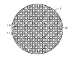
・ 図5に示される別例のように、複数個(ここでは16個)のハニカムフィルタ23を組み合わせて1つのセラミックフィルタ集合体21を製造してもよい。集合体21を構成する角柱状ハニカムフィルタ23の外周面は、互いにセラミック質シール材層22を介して接着されている。各ハニカムフィルタ23は、そのセル壁13の比表面積は前記実施形態と同じに設定されている。すなわち、比表面積は、0.1m2/g〜1.0m2/gに設定されている。その結果、各ハニカムフィルタ23が束ねられた状態で一体化されている。このような構成にすれば、圧力損失を小さくすることは勿論のことながら、加熱による温度勾配に起因する応力によってクラックが発生するのを防止でき、熱衝撃にも強くなる。従って、比較的容易にフィルタの大型化を達成することができる。
【0045】
・ ハニカムフィルタ23の組み合わせ数は、前記別例のように16個でなくてもよく、任意の数にすることが可能である。この場合、サイズ・形状等の異なるハニカムフィルタ23を適宜組み合わせて使用することも勿論可能である。
【0046】
・ 実施形態においては、本発明のハニカムフィルタ(又はセラミックフィルタ集合体)を、ディーゼルエンジン2に取り付けられる排気ガス浄化装置用フィルタとして具体化していた。勿論、本発明のハニカムフィルタ(又はセラミックフィルタ集合体)は、排気ガス浄化装置用フィルタ以外のものとして具体化されることができる。その例としては、熱交換器用部材、高温流体や高温蒸気のための濾過フィルタ等が挙げられる。さらに、本発明の多孔質炭化珪素焼結体は、フィルタ以外の用途にも適用可能である。
【0047】
次に、特許請求の範囲に記載された技術的思想のほかに、前述した実施形態によって把握される技術的思想を以下に列挙する。
(1) 請求項1において、前記セル壁を構成する粒子の比表面積が0.1〜1.0m2/gの範囲に設定されていること。
【0048】
(2) 内燃機関の排気側に設けられたケーシングと、前記ケーシング内に収容され、排気ガス中に含まれるパティキュレートを除去する請求項1〜4のいずれかに記載のハニカムフィルタとを備えた排気ガス浄化装置。この構成にすれば、圧力損失を小さくすることができるので、車両の運転条件を妨げ、燃費の悪化、運転フィーリングの悪化を防止することができる。
【0049】
【発明の効果】
以上詳述したように、請求項1に記載の発明によれば、圧力損失を小さくすることができるハニカムフィルタを提供することができる。
【0050】
請求項2に記載の発明によれば、長期間にわたって効率のよい流体の浄化を行うことができる。
請求項3に記載の発明によれば、よりいっそう圧力損失を小さくすることに貢献できるばかりか、パティキュレートの捕集効率を高めることができる。
【0051】
請求項4に記載の発明によれば、圧力損失を小さくすることができるハニカムフィルタ集合体を提供することができる。
【図面の簡単な説明】
【図1】本発明を具体化した一実施形態の排気ガス浄化装置の全体概略図。
【図2】実施形態のハニカムフィルタの斜視図。
【図3】実施形態のハニカムフィルタのA−A線における断面図。
【図4】前記排気ガス浄化装置の要部拡大断面図。
【図5】複数個のハニカムフィルタを用いて構成される別例のセラミックフィルタ集合体の斜視図。
【符号の説明】
2…ディーゼルエンジン(内燃機関)、8…ケーシング、9…ハニカムフィルタ、13…セル壁。[0001]
BACKGROUND OF THE INVENTION
The present invention relates to a honeycomb filter and a honeycomb filter assembly.
[0002]
[Prior art]
The number of automobiles has increased dramatically since the beginning of this century, and the amount of exhaust gas emitted from the automobile's internal combustion engine has been increasing rapidly. In particular, various substances contained in exhaust gas emitted from a diesel engine cause pollution, and are now having a serious impact on the world environment. Recently, research results have reported that soot (diesel particulates) in exhaust gas sometimes causes allergic disorders and a decrease in the number of sperm. In other words, taking measures to remove diesel particulates in exhaust gas is considered an urgent issue for humanity.
[0003]
Under such circumstances, various types of exhaust gas purifying devices have been proposed. A general exhaust gas purifying apparatus has a structure in which a casing is provided in the middle of an exhaust pipe connected to an exhaust manifold of an engine, and a honeycomb filter having fine holes is disposed therein. As a material for forming a honeycomb filter, there are advantages such as high heat resistance, mechanical strength, high collection efficiency, chemical stability, and low pressure loss. Often used as a filter forming material.
[0004]
Here, “pressure loss” refers to a value obtained by subtracting a pressure value on the downstream side from a pressure value on the upstream side of the filter. The greatest factor causing pressure loss is that the exhaust gas undergoes resistance as it passes through the filter.
[0005]
The honeycomb filter has a large number of cells extending along its own axial direction. When exhaust gas passes through the honeycomb filter, diesel particulates are trapped by the cell walls. Accordingly, the diesel particulates collected in the honeycomb filter are ignited and burned when the temperature in the honeycomb filter reaches a predetermined value (ignition temperature). Recently, it has been found that particulates having a small particle size have a high colonization rate and a high health risk. Therefore, there is a high demand for supplementing small particle size particulates.
[0006]
[Problems to be solved by the invention]
However, if the specific surface area of the particles constituting the cell wall is small, the honeycomb filter becomes too dense, and the exhaust gas does not easily pass through the honeycomb filter, resulting in a large pressure loss. Therefore, there is a problem that the fuel consumption of the vehicle is deteriorated and the driving feeling is deteriorated.
[0007]
The present invention has been made in view of the above problems, and an object of the present invention is to provide a honeycomb filter and a honeycomb filter assembly with a small pressure loss.
[0008]
[Means for Solving the Problems]
Honeycomb in order to solve the above problem, in the present invention, a plurality of cells, and partitioned by cell walls made of porous material of α-type silicon carbide sintered body, purifies fluid including particulates with the cell wall in the filter, Ru honeycomb filter der specific surface area of the cell wall is composed of a α-type silicon carbide particles, characterized in that a 0.3 ~1.0 m 2 / g.
[0010]
Further, in the present invention, a plurality of cells, and partitioned by cell walls formed of a porous body of α-type silicon carbide sintered body, with a honeycomb filter for purifying a fluid containing particulates through the cell wall as a constituent member, The cell wall, which is an aggregate formed by integrating the honeycomb filters by adhering the outer peripheral surfaces of these components through a ceramic sealing material layer, and is configured by α-type silicon carbide particles the specific surface area of we propose a honeycomb filter assembly, which is a 0.3 ~1.0 m 2 / g.
[0011]
The “action” of the present invention will be described below. According to the present invention, the specific surface area of the particles constituting the cell wall is 0. Since it is 3 m 2 / g or more, the pressure loss can be reduced. That is, the specific surface area is 0. This is because if it is less than 3 m 2 / g, the honeycomb filter becomes too dense, and it becomes difficult for the fluid containing the particulates to pass through the honeycomb filter smoothly.
[0012]
In addition, according to the present invention, since the cell wall made of a silicon carbide sintered body is excellent in heat resistance, even if it is disposed in a place where the temperature tends to be high as described above, the cell wall may be altered or burnt out. There is no such thing. Therefore, efficient purification of the fluid can be performed over a long period of time.
[0013]
Further , according to the present invention, the cell wall made of a porous body can contribute not only to further reducing the pressure loss, but also to increase the particulate collection efficiency.
[0014]
DETAILED DESCRIPTION OF THE INVENTION
Hereinafter, an exhaust
[0015]
As shown in FIG. 1, this exhaust
[0016]
A
[0017]
As shown in FIG. 1, the casing 8 is formed so that the central portion thereof has a larger diameter than the
[0018]
A
[0019]
Since the
[0020]
As shown in FIGS. 2, 3, and 4, the
[0021]
The density of the cells is preferably 120 cells / inch 2 (18 cells / cm 2 ) or more, more specifically in the range of 120 to 180 cells / inch 2 . This is because if the cell density is less than 120, the contact area with the exhaust gas becomes small, and the purification performance of the
[0022]
The thickness of the
[0023]
The porosity of the
[0024]
When a porous silicon carbide sintered body is selected, the thermal conductivity of the
[0025]
The
[0026]
It is desirable that the impurities contained in the porous silicon carbide sintered body be suppressed to 5% by weight or less. The amount of impurities is preferably 1% by weight or less, and particularly preferably 0.1% by weight or less. This is because if the impurity exceeds 5% by weight, the impurity is biased to the grain boundary of the silicon carbide crystal particles, the strength at the grain boundary (bonding strength between crystal grains) is remarkably lowered, and the grain boundary is easily broken. Examples of impurities include Al, Fe, O, and free C.
[0027]
The material for forming the sealing
[0028]
Further, in such a
[0029]
Next, a procedure for manufacturing the
First, a ceramic raw material slurry used in an extrusion molding process and a sealing paste used in an end face sealing process are prepared in advance.
[0030]
As the ceramic raw material slurry, a mixture obtained by kneading a silicon carbide powder with an organic binder and water in predetermined amounts and kneading them is used. As the sealing paste, a silicon carbide powder blended with an organic binder, a lubricant, a plasticizer and water and kneaded is used.
[0031]
Next, the ceramic raw material slurry is put into an extruder and continuously extruded through a mold. Thereafter, the extruded honeycomb formed body is cut into equal lengths to obtain cylindrical honeycomb formed body cut pieces. Further, a predetermined amount of sealing paste is filled into one side opening of each cell of the cut piece, and both end faces of each cut piece are sealed.
[0032]
Subsequently, main firing is performed with the temperature and time set to predetermined conditions, and the honeycomb formed body cut piece and the sealing
[0033]
Next, the particulate trap action by the
Exhaust gas is supplied to the
[0034]
[Examples and Comparative Examples]
(Examples 1, 2 and comparative examples)
51.5% by weight of α-type silicon carbide powder having an average particle size of 10 μm and 22% by weight of α-type silicon carbide powder having an average particle size of 0.5 μm are wet-mixed, and the resulting mixture is mixed with an organic binder (methylcellulose) and water. And kneaded by adding 6.5 wt% and 20 wt% respectively.
[0035]
Next, by adding a small amount of a plasticizer and a lubricant to the kneaded product and further kneading, extrusion-molding was performed to obtain a honeycomb-shaped formed shape. Specifically, as the α-type silicon carbide powder, those having an average particle diameter of 10 μm use a product name: C-1000F manufactured by Yakushima Electric Works, and those having an average particle diameter of 0.5 μm are manufactured by Yakushima Electric Works, Ltd. Product name: GC-15 was used.
[0036]
Next, after this generated shaped body was dried using a microwave dryer, the air holes 12 of the shaped body were sealed with a sealing paste made of a porous silicon carbide sintered body. Next, the sealing paste was dried again using a dryer. Following the end face sealing step, the dried body was degreased at 400 ° C., and then further baked at 2250 ° C. in an atmospheric argon atmosphere.
[0037]
As a result, in Example 1, the
[0038]
Next, the
[0039]
[Table 1]
[0040]
Therefore, according to the example of the present embodiment, the following effects can be obtained.
(1) A casing 8 is provided on the exhaust side of the
[0041]
(2) Since the
[0042]
(3) The
[0043]
In addition, you may change embodiment of this invention as follows.
The shape of the
[0044]
As in another example shown in FIG. 5, a single
[0045]
The number of combinations of the honeycomb filters 23 does not have to be 16 as in the other example, and can be an arbitrary number. In this case, it is of course possible to use a combination of honeycomb filters 23 having different sizes and shapes as appropriate.
[0046]
In the embodiment, the honeycomb filter (or ceramic filter assembly) of the present invention is embodied as a filter for an exhaust gas purification device attached to the
[0047]
Next, in addition to the technical ideas described in the claims, the technical ideas grasped by the embodiment described above are listed below.
(1) In
[0048]
(2) A casing provided on the exhaust side of the internal combustion engine, and the honeycomb filter according to any one of
[0049]
【The invention's effect】
As described in detail above, according to the first aspect of the present invention, a honeycomb filter capable of reducing pressure loss can be provided.
[0050]
According to the invention described in
According to the third aspect of the invention, not only can the pressure loss be further reduced, but also the particulate collection efficiency can be increased.
[0051]
According to invention of
[Brief description of the drawings]
FIG. 1 is an overall schematic view of an exhaust gas purifying apparatus according to an embodiment embodying the present invention.
FIG. 2 is a perspective view of the honeycomb filter of the embodiment.
FIG. 3 is a cross-sectional view taken along line AA of the honeycomb filter of the embodiment.
FIG. 4 is an enlarged cross-sectional view of a main part of the exhaust gas purification device.
FIG. 5 is a perspective view of another example of a ceramic filter assembly configured using a plurality of honeycomb filters.
[Explanation of symbols]
2 ... Diesel engine (internal combustion engine), 8 ... Casing, 9 ... Honeycomb filter, 13 ... Cell wall.
Claims (2)
α型炭化珪素粒子によって構成されている前記セル壁の比表面積が0.3〜1.0m2/gであることを特徴とするハニカムフィルタ。A plurality of cells, and partitioned by cell walls made of porous material of α-type silicon carbide sintered body, in the honeycomb filter for purifying a fluid containing particulates through the cell walls,
A honeycomb filter characterized in that a specific surface area of the cell wall composed of α-type silicon carbide particles is 0.3 to 1.0 m 2 / g .
α型炭化珪素粒子によって構成されている前記セル壁の比表面積が0.3〜1.0m2/gであることを特徴とするハニカムフィルタ集合体。A plurality of cells, and partitioned by cell walls formed of a porous body of α-type silicon carbide sintered body, with a honeycomb filter for purifying a fluid containing particulates through the cell wall as a constituent member, the outer periphery of these components By bonding the surfaces together via a ceramic sealing material layer, an aggregate formed by integrating the honeycomb filters,
A honeycomb filter aggregate characterized in that a specific surface area of the cell wall composed of α-type silicon carbide particles is 0.3 to 1.0 m 2 / g .
Priority Applications (41)
| Application Number | Priority Date | Filing Date | Title |
|---|---|---|---|
| JP27840599A JP4146048B2 (en) | 1999-09-30 | 1999-09-30 | Honeycomb filter, honeycomb filter assembly, |
| EP04025971A EP1508356B1 (en) | 1999-09-29 | 2000-09-26 | Honeycomb filter and ceramic filter assembly |
| DE60041464T DE60041464D1 (en) | 1999-09-29 | 2000-09-26 | Honeycomb filter and arrangement of ceramic filters |
| ES04025973T ES2281733T3 (en) | 1999-09-29 | 2000-09-26 | BEE NEST FILTER AND CERAMIC FILTER SET. |
| ES04025969T ES2277654T3 (en) | 1999-09-29 | 2000-09-26 | BEE NEST FILTER AND CERAMIC FILTER SET. |
| EP04025973A EP1508357B1 (en) | 1999-09-29 | 2000-09-26 | Honeycomb filter and ceramic filter assembly |
| ES04025972T ES2324035T3 (en) | 1999-09-29 | 2000-09-26 | BEE NEST FILTER AND CERAMIC FILTER SET. |
| DE60032392T DE60032392T2 (en) | 1999-09-29 | 2000-09-26 | Honeycomb filter and arrangement of ceramic filters |
| DE60042036T DE60042036D1 (en) | 1999-09-29 | 2000-09-26 | Honeycomb filter element and arrangement with ceramic filters |
| ES04025971T ES2277656T3 (en) | 1999-09-29 | 2000-09-26 | BEE NEST FILTER AND CERAMIC FILTER SET. |
| EP06075589A EP1666121B1 (en) | 1999-09-29 | 2000-09-26 | Honeycomb filter and ceramic filter assembly |
| KR10-2003-7012780A KR100482271B1 (en) | 1999-09-29 | 2000-09-26 | Honeycomb filter and ceramic filter assembly, and exaust gas cleaning apparatus |
| DE60033977T DE60033977T2 (en) | 1999-09-29 | 2000-09-26 | Honeycomb filter and arrangement of ceramic filters |
| EP04025972A EP1508358B1 (en) | 1999-09-29 | 2000-09-26 | Honeycomb filter and ceramic filter assembly |
| DE60032952T DE60032952T2 (en) | 1999-09-29 | 2000-09-26 | Honeycomb filter and arrangement of ceramic filters |
| EP00962846A EP1142619B1 (en) | 1999-09-29 | 2000-09-26 | Honeycomb filter and ceramic filter assembly |
| EP06076658A EP1775009A1 (en) | 1999-09-29 | 2000-09-26 | Honeycomb filter and ceramic filter assembly |
| ES00962846T ES2276695T3 (en) | 1999-09-29 | 2000-09-26 | BEE NEST FILTER AND CERAMIC FILTER SET. |
| DE20023989U DE20023989U1 (en) | 1999-09-29 | 2000-09-26 | Ceramic filter arrangement |
| KR10-2001-7006635A KR100446205B1 (en) | 1999-09-29 | 2000-09-26 | Honeycomb filter and ceramic filter assembly, and exaust gas cleaning apparatus |
| DE20023986U DE20023986U1 (en) | 1999-09-29 | 2000-09-26 | Ceramic filter arrangement |
| PCT/JP2000/006599 WO2001023069A1 (en) | 1999-09-29 | 2000-09-26 | Honeycomb filter and ceramic filter assembly |
| EP06075590A EP1688171B2 (en) | 1999-09-29 | 2000-09-26 | Honeycomb filter and ceramic filter assembly |
| US09/856,751 US6669751B1 (en) | 1999-09-29 | 2000-09-26 | Honeycomb filter and ceramic filter assembly |
| DE20023990U DE20023990U1 (en) | 1999-09-29 | 2000-09-26 | Ceramic filter arrangement |
| DE60033133T DE60033133T2 (en) | 1999-09-29 | 2000-09-26 | WAVY FILTER AND ARRANGEMENT OF CERAMIC FILTERS |
| DE60043867T DE60043867D1 (en) | 1999-09-29 | 2000-09-26 | Honeycomb filter and arrangement of ceramic filters |
| EP04025970A EP1516659B1 (en) | 1999-09-29 | 2000-09-26 | Honeycomb filter and ceramic filter assembly |
| EP04025969A EP1508355B1 (en) | 1999-09-29 | 2000-09-26 | Honeycomb filter and ceramic filter assembly |
| ES04025970T ES2277655T3 (en) | 1999-09-29 | 2000-09-26 | BEE NEST FILTER AND CERAMIC FILTER SET. |
| DE20023987U DE20023987U1 (en) | 1999-09-29 | 2000-09-26 | Ceramic filter arrangement |
| ES06075589T ES2321331T3 (en) | 1999-09-29 | 2000-09-26 | BEE NEST FILTER AND CERAMIC FILTER SET. |
| DE60032391T DE60032391T2 (en) | 1999-09-29 | 2000-09-26 | Honeycomb filter and arrangement of ceramic filters |
| DE20023988U DE20023988U1 (en) | 1999-09-29 | 2000-09-26 | Ceramic filter arrangement |
| ES06075590T ES2341274T3 (en) | 1999-09-29 | 2000-09-26 | PANAL FILTER AND CERAMIC FILTER ASSEMBLY. |
| US10/671,418 US7112233B2 (en) | 1999-09-29 | 2003-09-26 | Honeycomb filter and ceramic filter assembly |
| US11/230,844 US7427309B2 (en) | 1999-09-29 | 2005-09-21 | Honeycomb filter and ceramic filter assembly |
| US12/032,255 US20080120950A1 (en) | 1999-09-29 | 2008-02-15 | Honeycomb filter and ceramic filter assembly |
| US12/770,658 US8080082B2 (en) | 1999-09-29 | 2010-04-29 | Honeycomb filter and method for producing the honeycomb filter |
| US12/959,419 US8083826B2 (en) | 1999-09-29 | 2010-12-03 | Honeycomb filter and method for producing the honeycomb filter |
| US13/214,140 US20110304084A1 (en) | 1999-09-29 | 2011-08-19 | Method for producing honeycomb filter and method for producing ceramic filter assembly |
Applications Claiming Priority (1)
| Application Number | Priority Date | Filing Date | Title |
|---|---|---|---|
| JP27840599A JP4146048B2 (en) | 1999-09-30 | 1999-09-30 | Honeycomb filter, honeycomb filter assembly, |
Publications (3)
| Publication Number | Publication Date |
|---|---|
| JP2001096112A JP2001096112A (en) | 2001-04-10 |
| JP2001096112A5 JP2001096112A5 (en) | 2004-12-24 |
| JP4146048B2 true JP4146048B2 (en) | 2008-09-03 |
Family
ID=17596899
Family Applications (1)
| Application Number | Title | Priority Date | Filing Date |
|---|---|---|---|
| JP27840599A Expired - Fee Related JP4146048B2 (en) | 1999-09-29 | 1999-09-30 | Honeycomb filter, honeycomb filter assembly, |
Country Status (1)
| Country | Link |
|---|---|
| JP (1) | JP4146048B2 (en) |
Cited By (2)
| Publication number | Priority date | Publication date | Assignee | Title |
|---|---|---|---|---|
| USD647607S1 (en) | 2008-05-27 | 2011-10-25 | Ibiden Co., Ltd. | Particulate filter for diesel engine |
| JP7070485B2 (en) | 2019-03-20 | 2022-05-18 | ブラザー工業株式会社 | Machine Tools |
Families Citing this family (7)
| Publication number | Priority date | Publication date | Assignee | Title |
|---|---|---|---|---|
| JP4812316B2 (en) | 2005-03-16 | 2011-11-09 | イビデン株式会社 | Honeycomb structure |
| EP1871525A2 (en) * | 2005-04-08 | 2008-01-02 | Saint-Gobain Centre de Recherches et d'Etudes Européen | Catalytic filter for filtering a gas comprising a coating and/or a joint with controlled porosity |
| CN100471570C (en) * | 2005-06-24 | 2009-03-25 | 揖斐电株式会社 | Honeycomb structure body, honeycomb structure body assembly and homeycomb catalyst |
| FR2889080B1 (en) * | 2005-07-28 | 2007-11-23 | Saint Gobain Ct Recherches | CATALYTIC SUPPORT AND FILTER BASED ON SILICON CARBIDE AND HIGH SPECIFIC SURFACE |
| KR100779893B1 (en) * | 2005-12-29 | 2007-11-28 | 이비덴 가부시키가이샤 | Honeycomb structure, honeycomb structure aggregate, and honeycomb catalyst |
| FR2910468B1 (en) * | 2006-12-21 | 2009-02-06 | Saint Gobain Ct Recherches | PROCESS FOR OBTAINING A POROUS STRUCTURE BASED ON SILICON CARBIDE |
| JP5338603B2 (en) * | 2009-09-30 | 2013-11-13 | 住友大阪セメント株式会社 | Porous film-forming coating material and porous film |
-
1999
- 1999-09-30 JP JP27840599A patent/JP4146048B2/en not_active Expired - Fee Related
Cited By (2)
| Publication number | Priority date | Publication date | Assignee | Title |
|---|---|---|---|---|
| USD647607S1 (en) | 2008-05-27 | 2011-10-25 | Ibiden Co., Ltd. | Particulate filter for diesel engine |
| JP7070485B2 (en) | 2019-03-20 | 2022-05-18 | ブラザー工業株式会社 | Machine Tools |
Also Published As
| Publication number | Publication date |
|---|---|
| JP2001096112A (en) | 2001-04-10 |
Similar Documents
| Publication | Publication Date | Title |
|---|---|---|
| JP4409959B2 (en) | Ceramic filter and exhaust gas purification device | |
| US7517502B2 (en) | Honeycomb structural body | |
| EP1508355B1 (en) | Honeycomb filter and ceramic filter assembly | |
| EP1752630B1 (en) | Honeycomb structural body | |
| US7314496B2 (en) | Honeycomb structure | |
| JP3965007B2 (en) | Porous silicon carbide sintered body, honeycomb filter, ceramic filter assembly | |
| US8283019B2 (en) | Honeycomb structured body | |
| US7455709B2 (en) | Honeycomb structural body | |
| JP4051163B2 (en) | Ceramic filter assembly | |
| JP3803009B2 (en) | Ceramic filter assembly | |
| EP1604719A2 (en) | Ceramic filter for exhaust gas purification | |
| EP1514588A1 (en) | Honeycomb structure body | |
| WO2003002231A1 (en) | Honeycomb structural body | |
| JP2003210922A (en) | Ceramic honeycomb filter | |
| JP2001096116A (en) | Ceramic filter aggregate and honeycomb filter | |
| JP2001162119A (en) | Ceramic filter aggregate | |
| JP4146048B2 (en) | Honeycomb filter, honeycomb filter assembly, | |
| JP4167814B2 (en) | Ceramic filter assembly | |
| JP2001096113A (en) | Honeycomb filter and exhaust gas cleaning apparatus | |
| JP2009012005A (en) | Honeycomb filter and filter aggregate | |
| JP2001096111A (en) | Porous silicon carbide sintered compact, honeycomb filter and ceramic filter aggregate | |
| JP2006061909A (en) | Ceramic filter assembly | |
| JP2002274947A (en) | Sintered porous silicon carbide, method for manufacturing the same and filter for diesel particulate | |
| JP2009019634A (en) | Exhaust emission control device | |
| JP2001097776A (en) | Porous silicon carbide sintered product, honeycomb filter, ceramic filter assembly |
Legal Events
| Date | Code | Title | Description |
|---|---|---|---|
| A521 | Written amendment |
Free format text: JAPANESE INTERMEDIATE CODE: A523 Effective date: 20040129 |
|
| A131 | Notification of reasons for refusal |
Free format text: JAPANESE INTERMEDIATE CODE: A131 Effective date: 20070911 |
|
| A521 | Written amendment |
Free format text: JAPANESE INTERMEDIATE CODE: A523 Effective date: 20071107 |
|
| TRDD | Decision of grant or rejection written | ||
| A01 | Written decision to grant a patent or to grant a registration (utility model) |
Free format text: JAPANESE INTERMEDIATE CODE: A01 Effective date: 20080610 |
|
| A01 | Written decision to grant a patent or to grant a registration (utility model) |
Free format text: JAPANESE INTERMEDIATE CODE: A01 |
|
| A61 | First payment of annual fees (during grant procedure) |
Free format text: JAPANESE INTERMEDIATE CODE: A61 Effective date: 20080619 |
|
| R150 | Certificate of patent or registration of utility model |
Free format text: JAPANESE INTERMEDIATE CODE: R150 |
|
| FPAY | Renewal fee payment (event date is renewal date of database) |
Free format text: PAYMENT UNTIL: 20110627 Year of fee payment: 3 |
|
| FPAY | Renewal fee payment (event date is renewal date of database) |
Free format text: PAYMENT UNTIL: 20110627 Year of fee payment: 3 |
|
| FPAY | Renewal fee payment (event date is renewal date of database) |
Free format text: PAYMENT UNTIL: 20120627 Year of fee payment: 4 |
|
| FPAY | Renewal fee payment (event date is renewal date of database) |
Free format text: PAYMENT UNTIL: 20130627 Year of fee payment: 5 |
|
| LAPS | Cancellation because of no payment of annual fees |