JP4051163B2 - Ceramic filter assembly - Google Patents
Ceramic filter assembly Download PDFInfo
- Publication number
- JP4051163B2 JP4051163B2 JP27712399A JP27712399A JP4051163B2 JP 4051163 B2 JP4051163 B2 JP 4051163B2 JP 27712399 A JP27712399 A JP 27712399A JP 27712399 A JP27712399 A JP 27712399A JP 4051163 B2 JP4051163 B2 JP 4051163B2
- Authority
- JP
- Japan
- Prior art keywords
- ceramic
- honeycomb
- filter
- material layer
- sealing material
- Prior art date
- Legal status (The legal status is an assumption and is not a legal conclusion. Google has not performed a legal analysis and makes no representation as to the accuracy of the status listed.)
- Expired - Lifetime
Links
Images


Description
【0001】
【発明の属する技術分野】
本発明は、セラミック焼結体からなる複数のハニカムフィルタを接着して一体化した構造のセラミックフィルタ集合体に関するものである。
【0002】
【従来の技術】
自動車の台数は今世紀に入って飛躍的に増加しており、それに比例して自動車の内燃機関から出される排気ガスの量も急激な増加の一途を辿っている。特にディーゼルエンジンの出す排気ガス中に含まれる種々の物質は、汚染を引き起こす原因となるため、現在では世界環境にとって深刻な影響を与えつつある。また、最近では排気ガス中の微粒子(ディーゼルパティキュレート)が、ときとしてアレルギー障害や精子数の減少を引き起こす原因となるとの研究結果も報告されている。つまり、排気ガス中の微粒子を除去する対策を講じることが、人類にとって急務の課題であると考えられている。
【0003】
このような事情のもと、従来より、多様多種の排気ガス浄化装置が提案されている。一般的な排気ガス浄化装置は、エンジンの排気マニホールドに連結された排気管の途上にケーシングを設け、その中に微細な孔を有するフィルタを配置した構造を有している。フィルタの形成材料としては、金属や合金のほか、セラミックがある。セラミックからなるフィルタの代表例としては、コーディエライト製のハニカムフィルタが知られている。最近では、耐熱性・機械的強度・捕集効率が高い、化学的に安定している、圧力損失が小さい等の利点があることから、多孔質炭化珪素焼結体をフィルタ形成材料として用いることが多い。
【0004】
ハニカムフィルタは自身の軸線方向に沿って延びる多数のセルを有している。排気ガスがフィルタを通り抜ける際、そのセル壁によって微粒子がトラップされる。その結果、排気ガス中から微粒子が除去される。
【0005】
しかし、多孔質炭化珪素焼結体製のハニカムフィルタは熱衝撃に弱い。そのため、大型化するほどフィルタにクラックが生じやすくなる。よって、クラックによる破損を避ける手段として、複数の小さなフィルタ個片を一体化して1つの大きなセラミックフィルタ集合体を製造する技術が近年提案されている。
【0006】
上述の集合体を製造する一般的な方法を簡単に紹介する。まず、押出成形機の金型を介してセラミック原料を連続的に押し出すことにより、四角柱状のハニカム成形体を形成する。ハニカム成形体を等しい長さに切断した後、その切断片を焼成してフィルタとする。焼成工程の後、フィルタの外周面同士をセラミック質シール材層を介して接着することにより、複数のフィルタを束ねて一体化する。以上の結果、所望のセラミックフィルタ集合体が完成する。
【0007】
そして、セラミックフィルタ集合体の外周面には、セラミックファイバ等からなるマット状の断熱材が巻き付けられる。この状態で、集合体は排気管の途上に設けられたケーシング内に収容される。
【0008】
【発明が解決しようとする課題】
ところが、従来技術のハニカムフィルタは全体的に角張った形状をしているため、外周面における角部に応力が集中しやすく、そこに欠け(チッピング)が生じることがあった。また、角部を起点としてシール材層側にクラックが発生することもあり、それが原因でセラミックフィルタ集合体が破壊に至るおそれがあった。また、集合体の破壊に至らない場合であっても、排気ガスのリークによって処理効率が低下しやすいという問題があった。
【0009】
本発明は上記の課題に鑑みてなされたものであり、その目的は、強度に優れたセラミックフィルタ集合体を提供することにある。
【0010】
【課題を解決するための手段】
上記の課題を解決するために、請求項1に記載の発明では、セラミック焼結体からなる複数の角柱状ハニカムフィルタの外周面同士をセラミック質シール材層を介して接着することにより、前記各ハニカムフィルタを一体化してなる集合体であって、各ハニカムフィルタの外周面における角部は面取りが施されたアール面となっており、そのアール面の曲率半径がR=0.3〜2.5mmであることを特徴とするセラミックフィルタ集合体をその要旨とする。
【0011】
請求項2に記載の発明は、請求項1において、前記ハニカムフィルタは多孔質炭化珪素焼結体からなるとした。
請求項3に記載の発明は、請求項1または2において、前記ハニカムフィルタは四角柱状であって、かつフィルタ軸線方向に直交する方向に沿って互いにずらした状態で配置されているとした。
【0013】
以下、本発明の「作用」について説明する。請求項1〜3に記載の発明によると、ハニカムフィルタの外周面における角部が好適範囲のアール面になっていることから、当該箇所への応力集中が回避される。従って、ハニカムフィルタの角部の欠けや、角部を起点としたシール材層のクラックが防止され、セラミックフィルタ集合体が破壊しにくくなる。前記曲率半径Rが0.3mm以下であると、角部への応力集中を十分に回避することができず、欠けやクラックの発生につながりやすい。逆に、Rが2.5mmを超えると、ハニカムフィルタの断面積が減少する結果、集合体の濾過能力が低下してしまう。
【0014】
請求項2に記載の発明によると、このハニカムフィルタは多孔質体からなるので、濾過能力が高くかつ圧力損失が小さい。しかも、炭化珪素焼結体からなるので、耐熱性及び熱伝導性に優れている。
【0015】
請求項3に記載の発明によると、四角柱状のハニカムフィルタをフィルタ軸線方向に直交する方向に沿って互いにずらした状態で配置することにより、シール材層が十字状に交わる箇所ができなくなる。その結果、集合体の破壊強度が向上するばかりでなく、集合体の径方向に沿った熱伝導性が向上する。
【0017】
【発明の実施の形態】
以下、本発明を具体化した一実施形態のディーゼルエンジン用の排気ガス浄化装置1を、図1〜図5に基づき詳細に説明する。
【0018】
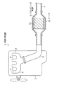
図1に示されるように、この排気ガス浄化装置1は、内燃機関としてのディーゼルエンジン2から排出される排気ガスを浄化するための装置である。ディーゼルエンジン2は、図示しない複数の気筒を備えている。各気筒には、金属材料からなる排気マニホールド3の分岐部4がそれぞれ連結されている。各分岐部4は1本のマニホールド本体5にそれぞれ接続されている。従って、各気筒から排出された排気ガスは一箇所に集中する。
【0019】
排気マニホールド3の下流側には、金属材料からなる第1排気管6及び第2排気管7が配設されている。第1排気管6の上流側端は、マニホールド本体5に連結されている。第1排気管6と第2排気管7との間には、同じく金属材料からなる筒状のケーシング8が配設されている。ケーシング8の上流側端は第1排気管6の下流側端に連結され、ケーシング8の下流側端は第2排気管7の上流側端に連結されている。排気管6,7の途上にケーシング8が配設されていると把握することもできる。そして、この結果、第1排気管6、ケーシング8及び第2排気管7の内部領域が互いに連通し、その中を排気ガスが流れるようになっている。
【0020】
図1に示されるように、ケーシング8はその中央部が排気管6,7よりも大径となるように形成されている。従って、ケーシング8の内部領域は、排気管6,7の内部領域に比べて広くなっている。このケーシング8内には、セラミックフィルタ集合体9が収容されている。
【0021】
集合体9の外周面とケーシング8の内周面との間には、断熱材10が配設されている。断熱材10はセラミックファイバを含んで形成されたマット状物であり、その厚さは数mm〜数十mmである。断熱材10は熱膨張性を有していることがよい。ここでいう熱膨張性とは、弾性構造を有するため熱応力を解放する機能があることを指す。その理由は、集合体9の最外周部から熱が逃げることを防止することにより、再生時のエネルギーロスを最小限に抑えるためである。また、再生時の熱によってセラミックファイバを膨張させることにより、排気ガスの圧力や走行による振動等のもたらすセラミックフィルタ集合体9の位置ずれを防止するためである。
【0022】
本実施形態において用いられるセラミックフィルタ集合体9は、上記のごとくディーゼルパティキュレートを除去するものであるため、一般にディーゼルパティキュレートフィルタ(DPF)と呼ばれる。図2,図4に示されるように、本実施形態の集合体9は、複数個のハニカムフィルタF1を束ねて一体化することによって形成されている。集合体9の中心部分に位置するハニカムフィルタF1は四角柱状であって、その外形寸法は33mm×33mm×167mmである(図3参照)。四角柱状のハニカムフィルタF1の周囲には、四角柱状でない異型のハニカムフィルタF1が複数個配置されている。その結果、全体としてみると円柱状のセラミックフィルタ集合体9(直径135mm前後)が構成されている。
【0023】
これらのハニカムフィルタF1は、セラミック焼結体の一種である多孔質炭化珪素焼結体製である。炭化珪素焼結体を採用した理由は、他のセラミックに比較して、とりわけ耐熱性及び熱伝導性に優れるという利点があるからである。炭化珪素以外の焼結体として、例えば窒化珪素、サイアロン、アルミナ、コーディエライト、ムライト等の焼結体を選択することもできる。
【0024】
図3等に示されるように、これらのハニカムフィルタF1は、ハニカム構造を備えている。ハニカム構造を採用した理由は、微粒子の捕集量が増加したときでも圧力損失が小さいという利点があるからである。各ハニカムフィルタF1には、断面略正方形状をなす複数の貫通孔12がその軸線方向に沿って規則的に形成されている。各貫通孔12は薄いセル壁13によって互いに仕切られている。セル壁13の外表面には、白金族元素(例えばPt等)やその他の金属元素及びその酸化物等からなる酸化触媒が担持されている。各貫通孔12の開口部は、いずれか一方の端面9a,9bの側において封止体14(ここでは多孔質炭化珪素焼結体)により封止されている。従って、端面9a,9b全体としてみると市松模様状を呈している。その結果、ハニカムフィルタF1には、断面四角形状をした多数のセルが形成されている。セルの密度は200個/インチ前後に設定され、セル壁13の厚さは0.3mm前後に設定され、セルピッチは1.8mm前後に設定されている。多数あるセルのうち、約半数のものは上流側端面9aにおいて開口し、残りのものは下流側端面9bにおいて開口している。
【0025】
ハニカムフィルタF1の平均気孔径は1μm〜50μm、さらには5μm〜20μmであることが好ましい。平均気孔径が1μm未満であると、微粒子の堆積によるハニカムフィルタF1の目詰まりが著しくなる。一方、平均気孔径が50μmを越えると、細かい微粒子を捕集することができなくなるため、濾過能力が低下してしまう。
【0026】
ハニカムフィルタF1の気孔率は30%〜70%、さらには40%〜60%であることが好ましい。気孔率が30%未満であると、ハニカムフィルタF1が緻密になりすぎてしまい、内部に排気ガスを流通させることができなくなるおそれがある。一方、気孔率が70%を越えると、ハニカムフィルタF1中に空隙が多くなりすぎてしまうため、強度的に弱くなりかつ微粒子の捕集効率が低下してしまうおそれがある。
【0027】
図4,図5に示されるように、合計16個のハニカムフィルタF1は、外周面同士がセラミック質シール材層15を介して互いに接着されている。
ここで、本実施形態のセラミック質シール材層15について詳細に述べる。
【0028】
シール材層15の厚さは0.3mm〜3mmであることが好ましく、さらには0.5mm〜2mmであることがより好ましい。
厚さが3mmを超えるようになると、たとえ熱伝導率が高くてもシール材層15が依然として大きな熱抵抗となり、ハニカムフィルタF1間の熱伝導が阻害されてしまう。しかも、集合体9においてハニカムフィルタF1部分の占める割合が相対的に減るため、濾過能力の低下につながってしまう。逆に、シール材層15の厚さが0.3mm未満であると、大きな熱抵抗にはならない反面、ハニカムフィルタF1同士を接着する力が不足してしまい、集合体9が破壊しやすくなる。
【0029】
前記シール材層15は、少なくとも無機繊維、無機バインダ、有機バインダ及び無機粒子からなり、かつ三次元的に交錯する前記無機繊維と無機粒子とを、前記無機バインダ及び有機バインダを介して互いに結合してなる弾性質素材からなることが望ましい。
【0030】
前記シール材層15に含まれる無機繊維としては、シリカ−アルミナファイバ、ムライトファイバ、アルミナファイバ及びシリカファイバから選ばれる少なくとも1種以上のセラミックファイバが挙げられる。これらのなかでも、特にシリカ−アルミナセラミックファイバを選択することが望ましい。シリカ−アルミナセラミックファイバは、弾性に優れるとともに熱応力を吸収する作用を示すからである。
【0031】
この場合、シール材層15におけるシリカ−アルミナセラミックファイバの含有量は、固形分で10重量%〜70重量%、好ましくは10重量%〜40重量%、より好ましくは20重量%〜30重量%である。含有量が10重量%未満であると、弾性体としての効果が低下するからである。一方、含有量が70重量%を超えると、熱伝導率の低下を招くばかりでなく、弾力性も低下するからである。
【0032】
シリカ−アルミナセラミックファイバにおけるショット含有量は、1重量%〜10重量%、好ましくは1重量%〜5重量%、より好ましくは1重量%〜3重量%である。ショット含有量を1重量%未満にすることは、製造上困難だからである。一方、ショット含有量が50重量%を超えると、ハニカムフィルタF1の外周面が傷付いてしまうからである。
【0033】
シリカ−アルミナセラミックファイバの繊維長は、1mm〜100mm、好ましくは1mm〜50mm、より好ましくは1mm〜20mmである。繊維長が1mm未満であると、弾性構造体を形成することができないからである。繊維長が100mmを超えると、繊維が毛玉化して無機微粒子の分散性が悪化するからである。また、シール材層15を3mm以下に薄くすることが困難になり、ハニカムフィルタF1間の熱伝導性の改善を図れなくなるからである。
【0034】
前記シール材層15に含まれる無機バインダとしては、シリカゾル及びアルミナゾルから選ばれる少なくとも1種以上のコロイダルゾルが望ましい。そのなかでも、特にシリカゾルを選択することが望ましい。その理由は、シリカゾルは入手しやすく、焼成により容易にSiO2 となるため、高温領域での接着剤として好適だからである。しかも、シリカゾルは絶縁性に優れているからである。
【0035】
この場合、シール材層15におけるシリカゾルの含有量は、固形分で1重量%〜30重量%、好ましくは1重量%〜15重量%、より好ましくは5重量%〜9重量%である。含有量が1重量%未満であると、接着強度の低下を招くからである。逆に、含有量が30重量%を超えると、熱伝導率の低下を招くからである。
【0036】
前記シール材層15に含まれる有機バインダとしては親水性有機高分子が好ましく、ポリビニルアルコール、メチルセルロース、エチルセルロース及びカルボメトキシセルロースから選ばれる少なくとも1種以上の多糖類がより好ましい。これらのなかでも、特にカルボキシメチルセルロースを選択することが望ましい。その理由は、カルボキシメチルセルロースは、シール材層15に好適な流動性を付与するため、常温領域において優れた接着性を示すからである。
【0037】
この場合、シール材層15におけるカルボキシメチルセルロースの含有量は、固形分で0.1重量%〜5.0重量%、好ましくは0.2重量%〜1.0重量%、より好ましくは0.4重量%〜0.6重量%である。含有量が0.1重量%未満であると、十分にマイグレーションを抑制することができないからである。なお、「マイグレーション」とは、被シール体間に充填されたシール材層15が硬化する際に、シール材層15中のバインダが、溶媒の乾燥除去に伴って移動する現象のことをいう。一方、含有量が5.0重量%を超えると、高温によって有機バインダが焼失し、シール材層15の強度が低下するからである。
【0038】
前記シール材層15に含まれる無機粒子としては、炭化珪素、窒化珪素及び窒化硼素から選ばれる少なくとも1種以上の無機粉末またはウィスカーを用いた弾性質素材であることが好ましい。このような炭化物や窒化物は、熱伝導率が非常に大きく、セラミックファイバ表面やコロイダルゾルの表面及び内部に介在して熱伝導性の向上に寄与するからである。
【0039】
上記炭化物及び窒化物の無機粒子のなかでも、特に炭化珪素粉末を選択することが望ましい。その理由は、炭化珪素は熱伝導率が極めて高いことに加え、セラミックファイバと馴染みやすいという性質があるからである。しかも、本実施形態では、被シール体であるハニカムフィルタF1が同種のもの、即ち多孔質炭化珪素製だからである。
【0040】
この場合、炭化珪素粉末の含有量は、固形分で3重量%〜80重量%、好ましくは10重量%〜60重量%、より好ましくは20重量%〜40重量%である。含有量が3重量%未満であると、シール材層15の熱伝導率の低下を招き、シール材層15が依然として大きな熱抵抗となるからである。一方、含有量が80重量%を超えると、高温時における接着強度の低下を招くからである。
【0041】
炭化珪素粉末の粒径は、0.01μm〜100μm、好ましくは0.1μm〜15μm、より好ましくは0.1μm〜10μmである。粒径が100μmを超えると、接着力及び熱伝導性の低下を招くからである。一方、粒径が0.01μm未満であると、シール材層15のコスト高につながるからである。
【0042】
ここでアール面18の曲率半径はR=0.3〜2.5mmであることが必要であり、さらにはR=0.7〜2.5mmであることがよく、特にはR=1.0〜2.0mmであることがなおよい。
【0043】
前記曲率半径Rが0.3mm以下であると、角部が依然として角張っていることから、角部への応力集中を十分に回避することができず、欠けやクラックの発生につながりやすいからである。逆に、Rが2.5mmを超えると、ハニカムフィルタF1の断面積が減少する結果、有効セル数が減ってしまい、集合体9の濾過能力の低下を招くからである。
【0044】
次に、上記のセラミックフィルタ集合体9を製造する手順を説明する。
まず、押出成形工程で使用するセラミック原料スラリー、端面封止工程で使用する封止用ペースト、フィルタ接着工程で使用するシール材層形成用ペーストをあらかじめ作製しておく。
【0045】
セラミック原料スラリーとしては、炭化珪素粉末に有機バインダ及び水を所定分量ずつ配合し、かつ混練したものを用いる。封止用ペーストとしては、炭化珪素粉末に有機バインダ、潤滑剤、可塑剤及び水を配合し、かつ混練したものを用いる。シール材層形成用ペーストとしては、無機繊維、無機バインダ、有機バインダ、無機粒子及び水を所定分量ずつ配合し、かつ混練したものを用いる。
【0046】
次に、前記セラミック原料スラリーを押出成形機に投入し、かつ金型を介してそれを連続的に押し出す。その後、押出成形されたハニカム成形体を等しい長さに切断し、四角柱状のハニカム成形体切断片を得る。ここでハニカム成形体切断の各角部に対して面取り加工を施し、所定曲率Rのアール面18を形成する。
【0047】
さらに、切断片の各セルの片側開口部に所定量ずつ封止用ペーストを充填し、各切断片の両端面を封止する。
続いて、温度・時間等を所定の条件に設定して本焼成を行い、ハニカム成形体切断片及び封止体14を完全に焼結させる。このようにして得られる多孔質炭化珪素焼結体製のハニカムフィルタF1は、この時点ではまだ全てのものが四角柱状である。各角部の面取り加工はこの時点で行われてもよい。
【0048】
なお、平均気孔径を6μm〜15μmとしかつ気孔率を35%〜50%とするために、本実施形態では焼成温度を2100℃〜2300℃に設定している。また、焼成時間を0.1時間〜5時間に設定している。また、焼成時の炉内雰囲気を不活性雰囲気とし、そのときの雰囲気の圧力を常圧としている。
【0049】
次に、必要に応じてハニカムフィルタF1の外周面にセラミック質からなる下地層を形成した後、さらにその上にシール材層形成用ペーストを塗布する。そして、このようなハニカムフィルタF1を16個用い、その外周面同士を互いに接着して一体化する。
【0050】
続く外形カット工程では、前記フィルタ接着工程を経て得られた断面正方形状の集合体9を研削し、外周部における不要部分を除去してその外形を整える。その結果、断面円形状のセラミックフィルタ集合体9とする。
【0051】
次に、上記のセラミックフィルタ集合体9による微粒子トラップ作用について簡単に説明する。
ケーシング8内に収容されたセラミックフィルタ集合体9には、上流側端面9aの側から排気ガスが供給される。第1排気管6を経て供給されてくる排気ガスは、まず、上流側端面9aにおいて開口するセル内に流入する。次いで、この排気ガスはセル壁13を通過し、それに隣接しているセル、即ち下流側端面9bにおいて開口するセルの内部に到る。そして、排気ガスは、同セルの開口を介してハニカムフィルタF1の下流側端面9bから流出する。しかし、排気ガス中に含まれる微粒子はセル壁13を通過することができず、そこにトラップされてしまう。その結果、浄化された排気ガスがハニカムフィルタF1の下流側端面9bから排出される。浄化された排気ガスは、さらに第2排気管7を通過した後、最終的には大気中へと放出される。また、トラップされた微粒子は、集合体9の内部温度が所定の温度に達すると、前記触媒の作用により着火して燃焼するようになっている。
【0052】
【実施例】
(実施例1)
(1)α型炭化珪素粉末51.5重量%とβ型炭化珪素粉末22重量%とを湿式混合し、得られた混合物に有機バインダ(メチルセルロース)と水とをそれぞれ6.5重量%、20重量%ずつ加えて混練した。次に、前記混練物に可塑剤と潤滑剤とを少量加えてさらに混練したものを押出成形することにより、ハニカム状の生成形体を得た。
【0053】
(2)次に、この生成形体をマイクロ波乾燥機を用いて乾燥した後、各角部を削ることで面取りを施し、各角部に曲率半径R=1.5mmのアール面18を形成した。その後、成形体の貫通孔12を多孔質炭化珪素焼結体製の封止用ペーストによって封止した。次いで、再び乾燥機を用いて封止用ペーストを乾燥させた。端面封止工程に続いて、この乾燥体を400℃で脱脂した後、さらにそれを常圧のアルゴン雰囲気下において2200℃で約3時間焼成した。その結果、多孔質炭化珪素焼結体製のハニカムフィルタF1を得た。
【0054】
(3)セラミックファイバ(アルミナシリケートセラミックファイバ、ショット含有率3%、繊維長さ0.1mm〜100mm)23.3重量%、平均粒径0.3μmの炭化珪素粉末30.2重量%、無機バインダとしてのシリカゾル(ゾルのSiO2の換算量は30%)7重量%、有機バインダとしてのカルボキシメチルセルロース0.5重量%及び水39重量%を混合・混練した。この混練物を適当な粘度に調整することにより、シール材層15の形成に使用されるペーストを作製した。
【0055】
(4)次に、ハニカムフィルタF1の外周面に前記シール材層形成用ペーストを均一に塗布するとともに、ハニカムフィルタF1の外周面同士を互いに密着させた状態で、50℃〜100℃×1時間の条件にて乾燥・硬化させる。その結果、ハニカムフィルタF1同士をシール材層15を介して接着する。ここではシール材層15の厚さを1.0mmに設定した。
【0056】
(5)次に、外形カットを実施して外形を整えることにより、断面円形状のセラミックフィルタ集合体9を完成させた。
次に、上記のようにして得られた集合体9に断熱材10を巻き付け、この状態で集合体9をケーシング8内に収容し、実際に排気ガスを供給した。そして、一定期間経過した後に集合体9を取り出して肉眼観察を行った。
【0057】
その結果、各角部を起点としたシール材層15のクラックは全く認められなかった。また、角部の欠けも全く認められなかった。従って、実施例1の集合体9は、極めて強度に優れていることが明らかとなった。
(実施例2,3)
実施例2では、アール面18の曲率半径をR=0.4mmに設定し、それ以外の事項については基本的に実施例1に順ずるようにして、セラミックフィルタ集合体9を作製した。実施例3では、アール面18の曲率半径をR=2.4mmに設定し、それ以外の事項については基本的に実施例1に順ずるようにして、セラミックフィルタ集合体9を作製した。
【0058】
次に、得られた2種の集合体9を、実施例1のときと同様に一定期間使用し、その後で肉眼観察を行ったところ、実施例1に匹敵する好適な結果が得られた。つまり、実施例2,3の集合体9も、極めて強度に優れていることが明らかとなった。
(実施例4)
実施例4では、セラミックファイバ(ムライトファイバ、ショット含有率5重量%,繊維長さ0.1mm〜100mm)25重量%、平均粒径1.0μmの窒化珪素粉末30重量%、無機バインダとしてのアルミナゾル(アルミナゾルの換算量は20%)7重量%、有機バインダとしてのポリビニルアルコール0.5重量%及びアルコール37.5重量%を混合・混練したものを、前記シール材層形成用ペーストとして使用した。それ以外の事項については実施例1に順ずるようにして、セラミックフィルタ集合体9を作製した。ここではシール材層15の厚さを1.0mmに設定し、各角部のアール面18の曲率半径をR=1.5mmに設定した。
【0059】
次に、得られた集合体9を、実施例1のときと同様に一定期間使用し、その後で肉眼観察を行ったところ、実施例1に匹敵する好適な結果が得られた。つまり、実施例4の集合体9も、極めて強度に優れていることが明らかとなった。
(実施例5)
実施例5は、セラミックファイバ(アルミナファイバ、ショット含有率4重量%,繊維長さ0.1mm〜100mm)23重量%、平均粒径1μmの窒化硼素粉末35重量%、無機バインダとしてのアルミナゾル(アルミナゾルの換算量は20%)8重量%、有機バインダとしてのエチルセルロース0.5重量%及びアセトン35.5重量%を混合・混練したものを、前記シール材層形成用ペーストとして使用した。それ以外の事項については実施例1に順ずるようにして、セラミックフィルタ集合体9を作製した。ここではシール材層15の厚さを1.0mmに設定し、各角部のアール面18の曲率半径をR=1.5mmに設定した。
【0060】
次に、得られた集合体9を、実施例1のときと同様に一定期間使用し、その後で肉眼観察を行ったところ、実施例1に匹敵する好適な結果が得られた。
(比較例)
比較例では、各角部に対する面取り加工を施さないようにし、それ以外の事項については基本的に実施例1に順ずるようにして、セラミックフィルタ集合体9を作製した。従って、集合体9を構成する各ハニカムフィルタF1は、角張ったものであった。
【0061】
次に、得られた集合体9を、実施例1のときと同様に一定期間使用し、その後で肉眼観察を行ったところ、応力の集中によって複数箇所にクラックや欠けが生じていた。従って、強度に劣るものとなっていた。
【0062】
従って、本実施形態の各実施例によれば以下のような効果を得ることができる。
(1)各実施例では、ハニカムフィルタF1の外周面における角部が好適曲率範囲のアール面18になっていることから、当該角部への応力集中を回避することができる。従って、ハニカムフィルタF1の角部の欠けや、角部を起点としたシール材層15のクラックが防止され、セラミックフィルタ集合体9が破壊しにくくなる。よって、強度に優れた集合体9を実現することが可能となり、これを用いた排気ガス浄化装置1は高強度かつ高濾過能力であって実用性に優れたものとなる。
【0063】
(2)各実施例では、多孔質体炭化珪素焼結体からなるハニカムフィルタ1を用いてる。従って、濾過能力が高くかつ圧力損失が小さくて、しかも耐熱性及び熱伝導性に優れた集合体9とすることができる。
【0064】
(3)各実施例では、いずれもシール材層15の厚さを0.3mm〜3mmという好適範囲内に設定している。このため、シール材層15が介在しているにもかかわらず、ハニカムフィルタF1間の熱伝導は阻害されにくくなる。従って、使用時において熱が集合体9の全体に均一にかつ速やかに伝導し、集合体9内に温度差が生じにくくなる。よって、集合体9の均熱性が向上し、部分的な燃え残りの発生も回避される。そして、このような集合体9を使用した排気ガス浄化装置1は、排気ガスの処理効率に優れたものとなる。
【0065】
また、シール材層15の厚さが上記範囲内であるならば、接着性や耐熱性等といった基本性能も維持されるため、シール材層15の製造が困難になることも回避できる。しかも、ハニカムフィルタF1同士を接着する力も備えているため、集合体9の破壊も回避できる。つまり、比較的製造しやすくて耐久性に優れた集合体9を実現することができる。
【0066】
なお、本発明の実施形態は以下のように変更してもよい。
・ ハニカムフィルタF1の組み合わせ数は、前記実施形態のように16個でなくてもよく、任意の数にすることが可能である。この場合、サイズ・形状等の異なるハニカムフィルタF1を適宜組み合わせて使用することも勿論可能である。
【0067】
・ 図6に示される別例のセラミックフィルタ集合体21のように、フィルタ軸線方向に直交する方向に沿って各ハニカムフィルタF1をあらかじめ互いにずらした状態にして、各ハニカムフィルタF1を接着しかつ一体化してもよい。このようにした場合には、ケーシング8への収容時にハニカムフィルタF1にずれが生じにくくなるため、集合体21の破壊強度が向上する。前記実施形態とは異なり、別例ではシール材層15が十字状に交わる箇所ができず、このことが破壊強度の向上に寄与しているものと考えられる。また、集合体21の径方向に沿った熱伝導性がさらに向上する結果、集合体21のよりいっそうの均熱化が図られる。
【0068】
・ アール面18は角部に対する面取り加工により形成されてもよいほか、生成形体を金型成形する際に同時に形成されてもよい。
・ 外形カット工程前におけるハニカムフィルタF1の形状は、実施形態のような断面正方形状の四角柱のみに限定されることはない。例えば、図7に示される別例のハニカムフィルタF2のような断面長方形状の四角柱でもよい。さらには、図8に示される別例のハニカムフィルタF3のように三角柱状にしたり、図9に示される別例のハニカムフィルタF4のように六角柱状にしても構わない。
【0069】
・ 実施形態においては、本発明のセラミックフィルタ集合体を、ディーゼルエンジン2に取り付けられる排気ガス浄化装置用フィルタとして具体化していた。勿論、本発明のセラミックフィルタ集合体は、排気ガス浄化装置用フィルタ以外のものとして具体化されることができ、例えば熱交換器用部材、高温流体や高温蒸気のための濾過フィルタ等として具体化されることができる。
【0070】
次に、特許請求の範囲に記載された技術的思想のほかに、前述した実施形態によって把握される技術的思想を以下に列挙する。
(1) 請求項1乃至3のいずれか1つにおいて、前記集合体はディーゼルパティキュレートフィルタであること。
【0071】
(2) 請求項1乃至3、技術的思想1,2のいずれか1つにおいて、前記シール材層は、少なくとも無機繊維、無機バインダ、有機バインダ及び無機粒子からなり、かつ三次元的に交錯する前記無機繊維と無機粒子とを、前記無機バインダ及び有機バインダを介して互いに結合してなる弾性質素材からなること。
【0072】
(3) 請求項1乃至3、技術的思想1,2のいずれか1つにおいて、前記シール材層は、固形分で10重量%〜70重量%のシリカ−アルミナセラミックファイバ、1重量%〜30重量%のシリカゾル、0.1重量%〜5.0重量%のカルボメトキシセルロース及び3重量%〜80重量%の炭化珪素粉末からなること。
【0073】
(4) 請求項1乃至3、技術的思想1乃至3のいずれか1つにおいて、前記シール材層の厚さは0.3mm〜3mmであること。従って、この技術的思想4に記載の発明によれば、十分な接着力を確保できるとともに、ハニカムフィルタ間での熱伝導が阻害されにくくなる。シール材層の厚さが3mmを超えるようになると、たとえ熱伝導率が高くてもシール材層が依然として大きな熱抵抗となり、ハニカムフィルタ間の熱伝導が阻害されてしまう。逆に、シール材層の厚さが0.3mm未満であると、大きな熱抵抗にはならない反面、ハニカムフィルタ同士を接着する力が不足してしまい、集合体が破壊しやすくなる。
【0074】
(5) 内燃機関の排気管の途上に設けられたケーシング内に、セラミック焼結体からなる複数のハニカムフィルタの外周面同士をセラミック質シール材層を介して接着することにより前記各ハニカムフィルタを一体化してなるセラミックフィルタ集合体を収容するとともに、その集合体の外周面と前記ケーシングの内周面とがなす隙間に断熱材を充填した排気ガス浄化装置において、各ハニカムフィルタの外周面における角部は面取りが施されたアール面となっており、そのアール面の曲率半径がR=0.3〜2.5mmであることを特徴とする排気ガス浄化装置。従って、この技術的思想5に記載の発明によれば、高強度かつ高濾過能力であって実用性に優れた装置を提供することができる。
【0075】
【発明の効果】
以上詳述したように、請求項1〜3に記載の発明によれば、強度に優れたセラミックフィルタ集合体を提供することができる。
【0076】
請求項2に記載の発明によれば、濾過能力が高くかつ圧力損失が小さく、耐熱性及び熱伝導性に優れた集合体とすることができる。
請求項3に記載の発明によれば、強度のさらなる向上及び集合体の均熱性向上を図ることができる。
【図面の簡単な説明】
【図1】本発明を具体化した一実施形態の排気ガス浄化装置の全体概略図。
【図2】実施形態のセラミックフィルタ集合体の斜視図。
【図3】実施形態のハニカムフィルタの斜視図。
【図4】前記排気ガス浄化装置の要部拡大断面図。
【図5】前記セラミックフィルタ集合体の要部拡大断面図。
【図6】別例のセラミックフィルタ集合体の要部拡大断面図。
【図7】別例のハニカムフィルタの斜視図。
【図8】別例のハニカムフィルタの斜視図。
【図9】別例のハニカムフィルタの斜視図。
【符号の説明】
9,21…セラミックフィルタ集合体、15…セラミック質シール材層、18…アール面、F1,F2,F3,F4…ハニカムフィルタ。[0001]
BACKGROUND OF THE INVENTION
The present invention relates to a ceramic filter assembly having a structure in which a plurality of honeycomb filters made of a ceramic sintered body are bonded and integrated. To the body It is related.
[0002]
[Prior art]
The number of automobiles has increased dramatically since the beginning of this century, and the amount of exhaust gas emitted from the automobile's internal combustion engine has been increasing rapidly. In particular, various substances contained in exhaust gas emitted from a diesel engine cause pollution, and are now having a serious impact on the world environment. Recently, research results have reported that particulates (diesel particulates) in exhaust gas sometimes cause allergic disorders and a decrease in the number of sperm. In other words, taking measures to remove particulates in exhaust gas is considered an urgent issue for humanity.
[0003]
Under such circumstances, various types of exhaust gas purification apparatuses have been proposed. A general exhaust gas purifying apparatus has a structure in which a casing is provided in the middle of an exhaust pipe connected to an exhaust manifold of an engine, and a filter having fine holes is disposed therein. As a material for forming the filter, there are ceramics in addition to metals and alloys. As a typical example of a filter made of ceramic, a honeycomb filter made of cordierite is known. Recently, there are advantages such as high heat resistance, mechanical strength, high collection efficiency, chemical stability, low pressure loss, etc., so use porous silicon carbide sintered body as a filter forming material. There are many.
[0004]
The honeycomb filter has a large number of cells extending along its own axial direction. As the exhaust gas passes through the filter, particulates are trapped by the cell walls. As a result, fine particles are removed from the exhaust gas.
[0005]
However, a honeycomb filter made of a porous silicon carbide sintered body is vulnerable to thermal shock. Therefore, the larger the size is, the easier the cracks are generated in the filter. Therefore, as a means for avoiding breakage due to cracks, a technique has recently been proposed in which a plurality of small filter pieces are integrated to produce one large ceramic filter assembly.
[0006]
A general method for manufacturing the above-described assembly will be briefly introduced. First, a rectangular column-shaped honeycomb formed body is formed by continuously extruding a ceramic raw material through a mold of an extruder. After the honeycomb formed body is cut into equal lengths, the cut piece is fired to obtain a filter. After the firing step, the plurality of filters are bundled and integrated by bonding the outer peripheral surfaces of the filters through a ceramic sealing material layer. As a result, a desired ceramic filter assembly is completed.
[0007]
A mat-like heat insulating material made of ceramic fiber or the like is wound around the outer peripheral surface of the ceramic filter assembly. In this state, the assembly is accommodated in a casing provided in the middle of the exhaust pipe.
[0008]
[Problems to be solved by the invention]
However, since the honeycomb filter of the prior art has a generally square shape, stress tends to concentrate on the corners on the outer peripheral surface, and chipping may occur there. In addition, cracks may occur on the sealing material layer side starting from the corners, which may cause destruction of the ceramic filter assembly. Further, even when the aggregates are not destroyed, there is a problem that the processing efficiency is likely to be lowered due to the leak of the exhaust gas.
[0009]
The present invention has been made in view of the above problems, and its purpose is to collect ceramic filters with excellent strength. Body It is to provide.
[0010]
[Means for Solving the Problems]
In order to solve the above-described problems, in the invention according to claim 1, the outer peripheral surfaces of a plurality of prismatic honeycomb filters made of a ceramic sintered body are bonded to each other via a ceramic sealing material layer. An aggregate formed by integrating honeycomb filters, and the corners on the outer peripheral surface of each honeycomb filter are rounded chamfered surfaces, and the curvature of the rounded surfaces radius R = 0.3-2.5 mm The gist of the ceramic filter assembly is characterized in that
[0011]
According to a second aspect of the present invention, in the first aspect, the honeycomb filter is made of a porous silicon carbide sintered body.
According to a third aspect of the present invention, in the first or second aspect, the honeycomb filter has a quadrangular prism shape and is arranged in a state of being shifted from each other along a direction orthogonal to the filter axial direction.
[0013]
The “action” of the present invention will be described below. According to the first to third aspects of the invention, the corners on the outer peripheral surface of the honeycomb filter are preferable. Suitable Since it is the rounded surface of the enclosure, stress concentration at the relevant location is avoided. Therefore, chipping of the corners of the honeycomb filter and cracking of the sealing material layer starting from the corners are prevented, and the ceramic filter aggregate is hardly broken. Curvature radius R is 0.3 mm If it is below, stress concentration on the corners cannot be avoided sufficiently, and chipping and cracking are likely to occur. Conversely, R is 2.5 mm If it exceeds 1, the cross-sectional area of the honeycomb filter decreases, and as a result, the filtration capacity of the aggregate decreases.
[0014]
According to the second aspect of the present invention, since this honeycomb filter is made of a porous body, it has a high filtration capacity and a small pressure loss. And since it consists of a silicon carbide sintered compact, it is excellent in heat resistance and heat conductivity.
[0015]
According to the invention described in
[0017]
DETAILED DESCRIPTION OF THE INVENTION
Hereinafter, an exhaust gas purification apparatus 1 for a diesel engine according to an embodiment of the present invention will be described in detail with reference to FIGS.
[0018]
As shown in FIG. 1, this exhaust gas purification device 1 is a device for purifying exhaust gas discharged from a diesel engine 2 as an internal combustion engine. The diesel engine 2 includes a plurality of cylinders (not shown). Each cylinder is connected with a
[0019]
A first exhaust pipe 6 and a
[0020]
As shown in FIG. 1, the
[0021]
A
[0022]
Since the ceramic filter aggregate 9 used in the present embodiment removes diesel particulates as described above, it is generally called a diesel particulate filter (DPF). As shown in FIGS. 2 and 4, the assembly 9 of the present embodiment is formed by bundling and integrating a plurality of honeycomb filters F1. The honeycomb filter F1 located at the central portion of the aggregate 9 has a quadrangular prism shape, and its outer dimensions are 33 mm × 33 mm × 167 mm (see FIG. 3). Around the quadrangular columnar honeycomb filter F1, a plurality of irregular honeycomb filters F1 that are not quadrangular columnar are arranged. As a result, a cylindrical ceramic filter assembly 9 (diameter around 135 mm) is configured as a whole.
[0023]
These honeycomb filters F1 are made of a porous silicon carbide sintered body which is a kind of ceramic sintered body. The reason for adopting the silicon carbide sintered body is that it has an advantage of being particularly excellent in heat resistance and thermal conductivity as compared with other ceramics. As a sintered body other than silicon carbide, for example, a sintered body such as silicon nitride, sialon, alumina, cordierite, and mullite can be selected.
[0024]
As shown in FIG. 3 and the like, these honeycomb filters F1 have a honeycomb structure. The reason for adopting the honeycomb structure is that there is an advantage that the pressure loss is small even when the amount of collected fine particles is increased. In each honeycomb filter F1, a plurality of through
[0025]
The average pore diameter of the honeycomb filter F1 is preferably 1 μm to 50 μm, more preferably 5 μm to 20 μm. When the average pore diameter is less than 1 μm, the honeycomb filter F1 is clogged due to the accumulation of fine particles. On the other hand, if the average pore diameter exceeds 50 μm, fine fine particles cannot be collected, and the filtration capacity is lowered.
[0026]
The porosity of the honeycomb filter F1 is preferably 30% to 70%, more preferably 40% to 60%. If the porosity is less than 30%, the honeycomb filter F1 becomes too dense, and the exhaust gas may not be allowed to flow inside. On the other hand, if the porosity exceeds 70%, the number of voids in the honeycomb filter F1 increases, so that the strength becomes weak and the collection efficiency of fine particles may be reduced.
[0027]
As shown in FIGS. 4 and 5, a total of 16 honeycomb filters F <b> 1 have their outer peripheral surfaces bonded to each other via a ceramic
Here, the ceramic
[0028]
The thickness of the sealing
When the thickness exceeds 3 mm, the sealing
[0029]
The sealing
[0030]
Examples of the inorganic fiber contained in the sealing
[0031]
In this case, the content of the silica-alumina ceramic fiber in the sealing
[0032]
The shot content in the silica-alumina ceramic fiber is 1 wt% to 10 wt%, preferably 1 wt% to 5 wt%, more preferably 1 wt% to 3 wt%. This is because it is difficult to make the shot content less than 1% by weight. On the other hand, if the shot content exceeds 50% by weight, the outer peripheral surface of the honeycomb filter F1 is damaged.
[0033]
The fiber length of the silica-alumina ceramic fiber is 1 mm to 100 mm, preferably 1 mm to 50 mm, more preferably 1 mm to 20 mm. This is because the elastic structure cannot be formed when the fiber length is less than 1 mm. This is because if the fiber length exceeds 100 mm, the fibers become pilled and the dispersibility of the inorganic fine particles deteriorates. Further, it is difficult to make the sealing
[0034]
The inorganic binder contained in the sealing
[0035]
In this case, the content of the silica sol in the sealing
[0036]
The organic binder contained in the sealing
[0037]
In this case, the content of carboxymethyl cellulose in the sealing
[0038]
The inorganic particles contained in the sealing
[0039]
Among the carbide and nitride inorganic particles, it is particularly preferable to select silicon carbide powder. The reason is that silicon carbide has a property of being easily compatible with ceramic fibers in addition to extremely high thermal conductivity. Moreover, in the present embodiment, the honeycomb filter F1 that is the sealed object is the same type, that is, made of porous silicon carbide.
[0040]
In this case, the content of the silicon carbide powder is 3% by weight to 80% by weight, preferably 10% by weight to 60% by weight, and more preferably 20% by weight to 40% by weight in terms of solid content. This is because if the content is less than 3% by weight, the thermal conductivity of the sealing
[0041]
The particle size of the silicon carbide powder is 0.01 μm to 100 μm, preferably 0.1 μm to 15 μm, more preferably 0.1 μm to 10 μm. This is because if the particle size exceeds 100 μm, the adhesive force and the thermal conductivity are reduced. On the other hand, when the particle size is less than 0.01 μm, the cost of the sealing
[0042]
Where the curvature of the
[0043]
Curvature radius R is 0.3 mm This is because the corners are still angular if the following, the stress concentration on the corners cannot be sufficiently avoided, and the cracks and cracks are likely to occur. Conversely, R is 2.5 mm This is because the number of effective cells is reduced as a result of the reduction of the cross-sectional area of the honeycomb filter F1, and the filtration capacity of the aggregate 9 is reduced.
[0044]
Next, a procedure for manufacturing the ceramic filter assembly 9 will be described.
First, a ceramic raw material slurry used in an extrusion molding process, a sealing paste used in an end face sealing process, and a sealing material layer forming paste used in a filter bonding process are prepared in advance.
[0045]
As the ceramic raw material slurry, a mixture obtained by kneading a silicon carbide powder with an organic binder and water in predetermined amounts and kneading them is used. As the sealing paste, a silicon carbide powder blended with an organic binder, a lubricant, a plasticizer and water and kneaded is used. As the paste for forming the sealing material layer, an inorganic fiber, an inorganic binder, an organic binder, inorganic particles, and water are blended in predetermined amounts and kneaded.
[0046]
Next, the ceramic raw material slurry is put into an extruder and continuously extruded through a mold. Thereafter, the extruded honeycomb formed body is cut into equal lengths to obtain a rectangular pillar-shaped honeycomb formed body cut piece. Here, each corner of the honeycomb formed body is chamfered to form a
[0047]
Further, a predetermined amount of sealing paste is filled into one side opening of each cell of the cut piece, and both end faces of each cut piece are sealed.
Subsequently, the main firing is performed by setting the temperature, time, and the like to predetermined conditions, and the honeycomb formed body cut piece and the sealing
[0048]
In this embodiment, the firing temperature is set to 2100 ° C. to 2300 ° C. in order to set the average pore diameter to 6 μm to 15 μm and the porosity to 35% to 50%. The firing time is set to 0.1 hours to 5 hours. Moreover, the atmosphere in the furnace at the time of baking is made into an inert atmosphere, and the pressure of the atmosphere at that time is made into a normal pressure.
[0049]
Next, if necessary, a base layer made of a ceramic material is formed on the outer peripheral surface of the honeycomb filter F1, and a sealing material layer forming paste is further applied thereon. And 16 such honey-comb filters F1 are used, and the outer peripheral surfaces are mutually adhere | attached and integrated.
[0050]
In the subsequent outer shape cutting step, the aggregate 9 having a square section obtained through the filter adhering step is ground, and unnecessary portions on the outer peripheral portion are removed to adjust the outer shape. As a result, a ceramic filter assembly 9 having a circular cross section is obtained.
[0051]
Next, the particulate trap action by the ceramic filter assembly 9 will be briefly described.
Exhaust gas is supplied to the ceramic filter assembly 9 housed in the
[0052]
【Example】
Example 1
(1) Wet-mixing 51.5% by weight of α-type silicon carbide powder and 22% by weight of β-type silicon carbide powder, and adding 6.5% by weight and 20% of organic binder (methyl cellulose) and water to the resulting mixture, respectively. It added and knead | mixed weight%. Next, by adding a small amount of a plasticizer and a lubricant to the kneaded product and further kneading, extrusion-molding was performed to obtain a honeycomb-shaped formed shape.
[0053]
(2) Next, after drying this generated shape using a microwave dryer, chamfering is performed by shaving each corner, curvature radius R = 1.5 mm The rounded
[0054]
(3) Ceramic fiber (alumina silicate ceramic fiber, shot
[0055]
(4) Next, the paste for forming the sealing material layer is uniformly applied to the outer peripheral surface of the honeycomb filter F1, and the outer peripheral surfaces of the honeycomb filter F1 are in close contact with each other, and are 50 ° C. to 100 ° C. × 1 hour. Dry and cure under the following conditions. As a result, the honeycomb filters F1 are bonded to each other through the sealing
[0056]
(5) Next, the outer shape was cut to prepare the outer shape, thereby completing the ceramic filter assembly 9 having a circular cross section.
Next, the
[0057]
As a result, no cracks were found in the sealing
(Examples 2 and 3)
In Example 2, the curvature of the
[0058]
Next, when the obtained two types of aggregates 9 were used for a certain period of time in the same manner as in Example 1 and then observed with the naked eye, suitable results comparable to Example 1 were obtained. That is, it has been clarified that the assembly 9 of Examples 2 and 3 is extremely excellent in strength.
Example 4
In Example 4, 25% by weight of ceramic fiber (mullite fiber, shot content 5% by weight, fiber length 0.1 mm to 100 mm), 30% by weight of silicon nitride powder having an average particle size of 1.0 μm, alumina sol as an inorganic binder (Conversion amount of alumina sol 20%) 7% by weight, 0.5% by weight of polyvinyl alcohol as an organic binder and 37.5% by weight of alcohol were mixed and kneaded, and used as the sealing material layer forming paste. Otherwise, the ceramic filter assembly 9 was produced in the same manner as in Example 1. Here, the thickness of the sealing
[0059]
Next, when the obtained assembly 9 was used for a certain period of time in the same manner as in Example 1 and then observed with the naked eye, a suitable result comparable to that in Example 1 was obtained. In other words, it was revealed that the assembly 9 of Example 4 was extremely excellent in strength.
(Example 5)
In Example 5, ceramic fiber (alumina fiber, shot
[0060]
Next, when the obtained assembly 9 was used for a certain period of time in the same manner as in Example 1 and then observed with the naked eye, a suitable result comparable to that in Example 1 was obtained.
(Comparative example)
In the comparative example, the chamfering process was not performed on each corner, and the ceramic filter assembly 9 was manufactured in the same manner as in Example 1 except for the other matters. Therefore, each honeycomb filter F1 constituting the aggregate 9 was angular.
[0061]
Next, when the obtained assembly 9 was used for a certain period of time in the same manner as in Example 1 and then observed with the naked eye, cracks and chips were generated at a plurality of locations due to stress concentration. Therefore, it was inferior in strength.
[0062]
Therefore, according to each example of the present embodiment, the following effects can be obtained.
(1) In each of the embodiments, the corner portion on the outer peripheral surface of the honeycomb filter F1 is the
[0063]
(2) In each embodiment, the honeycomb filter 1 made of a porous silicon carbide sintered body is used. Therefore, it can be set as the aggregate | assembly 9 with high filtration capability, a small pressure loss, and excellent in heat resistance and heat conductivity.
[0064]
(3) In each Example, the thickness of the sealing
[0065]
Further, if the thickness of the sealing
[0066]
In addition, you may change embodiment of this invention as follows.
The number of combinations of the honeycomb filter F1 does not have to be 16 as in the above-described embodiment, and can be any number. In this case, it is of course possible to use honeycomb filters F1 having different sizes and shapes in appropriate combinations.
[0067]
As in another example of the
[0068]
The
-The shape of the honeycomb filter F1 before the outer shape cutting step is not limited to a square column having a square cross section as in the embodiment. For example, it may be a quadrangular prism having a rectangular cross section like the honeycomb filter F2 of another example shown in FIG. Further, it may have a triangular prism shape as in another example honeycomb filter F3 shown in FIG. 8, or a hexagonal column shape like another example honeycomb filter F4 shown in FIG.
[0069]
In the embodiment, the ceramic filter assembly of the present invention is embodied as a filter for an exhaust gas purification device attached to the diesel engine 2. Of course, the ceramic filter assembly of the present invention can be embodied as other than a filter for an exhaust gas purification device, for example, a heat exchanger member, a filtration filter for high temperature fluid or high temperature steam, or the like. Can.
[0070]
Next, in addition to the technical ideas described in the claims, the technical ideas grasped by the embodiment described above are listed below.
(1) In any one of Claims 1 thru | or 3, the said aggregate | assembly is a diesel particulate filter.
[0071]
(2) In any one of claims 1 to 3 and technical ideas 1 and 2, the sealing material layer includes at least inorganic fibers, an inorganic binder, an organic binder, and inorganic particles, and is three-dimensionally crossed. It consists of an elastic material formed by bonding the inorganic fibers and the inorganic particles to each other via the inorganic binder and the organic binder.
[0072]
(3) In any one of claims 1 to 3 and technical ideas 1 and 2, the sealing material layer has a silica-alumina ceramic fiber having a solid content of 10 wt% to 70 wt%, and 1 wt% to 30 wt%. Consisting of 0.1% by weight to 5.0% by weight carbomethoxycellulose and 3% to 80% by weight silicon carbide powder.
[0073]
(4) In any one of claims 1 to 3 and technical ideas 1 to 3, the thickness of the sealing material layer is 0.3 mm to 3 mm. Therefore, according to the invention described in this
[0074]
(5) Each honeycomb filter is bonded to the outer peripheral surfaces of a plurality of honeycomb filters made of a ceramic sintered body through a ceramic sealing material layer in a casing provided in the middle of an exhaust pipe of an internal combustion engine. In an exhaust gas purifying apparatus that accommodates an integrated ceramic filter assembly and is filled with a heat insulating material in a gap formed between the outer peripheral surface of the assembly and the inner peripheral surface of the casing, corners on the outer peripheral surface of each honeycomb filter The part has a rounded chamfered surface, and the curvature of the rounded surface radius R = 0.3-2.5 mm An exhaust gas purification apparatus characterized by Therefore, according to the invention described in this technical idea 5, it is possible to provide an apparatus that has high strength and high filtering ability and is excellent in practicality.
[0075]
【The invention's effect】
As described above in detail, according to the first to third aspects of the invention, a ceramic filter assembly having excellent strength can be provided.
[0076]
According to invention of Claim 2, it can be set as the aggregate | assembly excellent in heat resistance and heat conductivity that filtration capability is high, pressure loss is small.
According to the invention described in
[Brief description of the drawings]
FIG. 1 is an overall schematic view of an exhaust gas purifying apparatus according to an embodiment embodying the present invention.
FIG. 2 is a perspective view of the ceramic filter assembly of the embodiment.
FIG. 3 is a perspective view of the honeycomb filter of the embodiment.
FIG. 4 is an enlarged cross-sectional view of a main part of the exhaust gas purification device.
FIG. 5 is an enlarged cross-sectional view of a main part of the ceramic filter assembly.
FIG. 6 is an enlarged cross-sectional view of a main part of another example of a ceramic filter assembly.
FIG. 7 is a perspective view of another example of a honeycomb filter.
FIG. 8 is a perspective view of another example of a honeycomb filter.
FIG. 9 is a perspective view of another example of a honeycomb filter.
[Explanation of symbols]
9, 21 ... Ceramic filter assembly, 15 ... Ceramic sealing material layer, 18 ... Earl surface, F1, F2, F3, F4 ... Honeycomb filter.
Claims (3)
Priority Applications (41)
| Application Number | Priority Date | Filing Date | Title |
|---|---|---|---|
| JP27712399A JP4051163B2 (en) | 1999-09-29 | 1999-09-29 | Ceramic filter assembly |
| ES04025970T ES2277655T3 (en) | 1999-09-29 | 2000-09-26 | BEE NEST FILTER AND CERAMIC FILTER SET. |
| PCT/JP2000/006599 WO2001023069A1 (en) | 1999-09-29 | 2000-09-26 | Honeycomb filter and ceramic filter assembly |
| ES06075590T ES2341274T3 (en) | 1999-09-29 | 2000-09-26 | PANAL FILTER AND CERAMIC FILTER ASSEMBLY. |
| EP04025973A EP1508357B1 (en) | 1999-09-29 | 2000-09-26 | Honeycomb filter and ceramic filter assembly |
| EP06075589A EP1666121B1 (en) | 1999-09-29 | 2000-09-26 | Honeycomb filter and ceramic filter assembly |
| DE20023987U DE20023987U1 (en) | 1999-09-29 | 2000-09-26 | Ceramic filter arrangement |
| EP04025969A EP1508355B1 (en) | 1999-09-29 | 2000-09-26 | Honeycomb filter and ceramic filter assembly |
| DE60033977T DE60033977T2 (en) | 1999-09-29 | 2000-09-26 | Honeycomb filter and arrangement of ceramic filters |
| EP04025970A EP1516659B1 (en) | 1999-09-29 | 2000-09-26 | Honeycomb filter and ceramic filter assembly |
| DE60043867T DE60043867D1 (en) | 1999-09-29 | 2000-09-26 | Honeycomb filter and arrangement of ceramic filters |
| ES04025972T ES2324035T3 (en) | 1999-09-29 | 2000-09-26 | BEE NEST FILTER AND CERAMIC FILTER SET. |
| DE60032392T DE60032392T2 (en) | 1999-09-29 | 2000-09-26 | Honeycomb filter and arrangement of ceramic filters |
| EP06076658A EP1775009A1 (en) | 1999-09-29 | 2000-09-26 | Honeycomb filter and ceramic filter assembly |
| EP00962846A EP1142619B1 (en) | 1999-09-29 | 2000-09-26 | Honeycomb filter and ceramic filter assembly |
| DE60032391T DE60032391T2 (en) | 1999-09-29 | 2000-09-26 | Honeycomb filter and arrangement of ceramic filters |
| DE20023988U DE20023988U1 (en) | 1999-09-29 | 2000-09-26 | Ceramic filter arrangement |
| ES06075589T ES2321331T3 (en) | 1999-09-29 | 2000-09-26 | BEE NEST FILTER AND CERAMIC FILTER SET. |
| DE20023986U DE20023986U1 (en) | 1999-09-29 | 2000-09-26 | Ceramic filter arrangement |
| EP06075590A EP1688171B2 (en) | 1999-09-29 | 2000-09-26 | Honeycomb filter and ceramic filter assembly |
| US09/856,751 US6669751B1 (en) | 1999-09-29 | 2000-09-26 | Honeycomb filter and ceramic filter assembly |
| KR10-2003-7012780A KR100482271B1 (en) | 1999-09-29 | 2000-09-26 | Honeycomb filter and ceramic filter assembly, and exaust gas cleaning apparatus |
| EP04025972A EP1508358B1 (en) | 1999-09-29 | 2000-09-26 | Honeycomb filter and ceramic filter assembly |
| ES04025969T ES2277654T3 (en) | 1999-09-29 | 2000-09-26 | BEE NEST FILTER AND CERAMIC FILTER SET. |
| ES04025971T ES2277656T3 (en) | 1999-09-29 | 2000-09-26 | BEE NEST FILTER AND CERAMIC FILTER SET. |
| DE60041464T DE60041464D1 (en) | 1999-09-29 | 2000-09-26 | Honeycomb filter and arrangement of ceramic filters |
| DE20023990U DE20023990U1 (en) | 1999-09-29 | 2000-09-26 | Ceramic filter arrangement |
| DE60033133T DE60033133T2 (en) | 1999-09-29 | 2000-09-26 | WAVY FILTER AND ARRANGEMENT OF CERAMIC FILTERS |
| KR10-2001-7006635A KR100446205B1 (en) | 1999-09-29 | 2000-09-26 | Honeycomb filter and ceramic filter assembly, and exaust gas cleaning apparatus |
| DE20023989U DE20023989U1 (en) | 1999-09-29 | 2000-09-26 | Ceramic filter arrangement |
| DE60032952T DE60032952T2 (en) | 1999-09-29 | 2000-09-26 | Honeycomb filter and arrangement of ceramic filters |
| ES00962846T ES2276695T3 (en) | 1999-09-29 | 2000-09-26 | BEE NEST FILTER AND CERAMIC FILTER SET. |
| EP04025971A EP1508356B1 (en) | 1999-09-29 | 2000-09-26 | Honeycomb filter and ceramic filter assembly |
| ES04025973T ES2281733T3 (en) | 1999-09-29 | 2000-09-26 | BEE NEST FILTER AND CERAMIC FILTER SET. |
| DE60042036T DE60042036D1 (en) | 1999-09-29 | 2000-09-26 | Honeycomb filter element and arrangement with ceramic filters |
| US10/671,418 US7112233B2 (en) | 1999-09-29 | 2003-09-26 | Honeycomb filter and ceramic filter assembly |
| US11/230,844 US7427309B2 (en) | 1999-09-29 | 2005-09-21 | Honeycomb filter and ceramic filter assembly |
| US12/032,255 US20080120950A1 (en) | 1999-09-29 | 2008-02-15 | Honeycomb filter and ceramic filter assembly |
| US12/770,658 US8080082B2 (en) | 1999-09-29 | 2010-04-29 | Honeycomb filter and method for producing the honeycomb filter |
| US12/959,419 US8083826B2 (en) | 1999-09-29 | 2010-12-03 | Honeycomb filter and method for producing the honeycomb filter |
| US13/214,140 US20110304084A1 (en) | 1999-09-29 | 2011-08-19 | Method for producing honeycomb filter and method for producing ceramic filter assembly |
Applications Claiming Priority (1)
| Application Number | Priority Date | Filing Date | Title |
|---|---|---|---|
| JP27712399A JP4051163B2 (en) | 1999-09-29 | 1999-09-29 | Ceramic filter assembly |
Related Child Applications (1)
| Application Number | Title | Priority Date | Filing Date |
|---|---|---|---|
| JP2004022998A Division JP2004216375A (en) | 2004-01-30 | 2004-01-30 | Ceramic filter aggregate and honeycomb filter |
Publications (3)
| Publication Number | Publication Date |
|---|---|
| JP2001096117A JP2001096117A (en) | 2001-04-10 |
| JP2001096117A5 JP2001096117A5 (en) | 2004-12-24 |
| JP4051163B2 true JP4051163B2 (en) | 2008-02-20 |
Family
ID=17579121
Family Applications (1)
| Application Number | Title | Priority Date | Filing Date |
|---|---|---|---|
| JP27712399A Expired - Lifetime JP4051163B2 (en) | 1999-09-29 | 1999-09-29 | Ceramic filter assembly |
Country Status (1)
| Country | Link |
|---|---|
| JP (1) | JP4051163B2 (en) |
Cited By (1)
| Publication number | Priority date | Publication date | Assignee | Title |
|---|---|---|---|---|
| USD647607S1 (en) | 2008-05-27 | 2011-10-25 | Ibiden Co., Ltd. | Particulate filter for diesel engine |
Families Citing this family (22)
| Publication number | Priority date | Publication date | Assignee | Title |
|---|---|---|---|---|
| JP3503823B2 (en) * | 2001-02-15 | 2004-03-08 | 日立金属株式会社 | Porous ceramic honeycomb structure |
| JP4715032B2 (en) * | 2001-05-25 | 2011-07-06 | トヨタ自動車株式会社 | Diesel exhaust gas purification filter |
| EP1489274B2 (en) * | 2002-03-04 | 2013-06-05 | Ibiden Co., Ltd. | Use of a honeycomb filter for exhaust gas purification |
| CN1305548C (en) * | 2002-04-09 | 2007-03-21 | 揖斐电株式会社 | Honeycomb filter for clarification of exhaust gas |
| DE20321503U1 (en) | 2002-09-13 | 2007-08-30 | Ibiden Co., Ltd., Ogaki | Honeycomb structural body |
| JPWO2004024295A1 (en) * | 2002-09-13 | 2006-01-05 | イビデン株式会社 | Honeycomb structure |
| PL1752630T3 (en) | 2003-06-05 | 2008-07-31 | Ibiden Co Ltd | Honeycomb structural body |
| PL1514588T3 (en) | 2003-06-23 | 2007-09-28 | Ibiden Co Ltd | Honeycomb structure body |
| ATE386581T1 (en) | 2003-10-20 | 2008-03-15 | Ibiden Co Ltd | HONEYCOMB STRUCTURE |
| JP4439236B2 (en) | 2003-10-23 | 2010-03-24 | イビデン株式会社 | Honeycomb structure |
| JP2005144250A (en) * | 2003-11-12 | 2005-06-09 | Ngk Insulators Ltd | Honeycomb structure body |
| JP2004216375A (en) * | 2004-01-30 | 2004-08-05 | Ibiden Co Ltd | Ceramic filter aggregate and honeycomb filter |
| WO2006137160A1 (en) | 2005-06-24 | 2006-12-28 | Ibiden Co., Ltd. | Honeycomb structure body |
| CN101006024B (en) | 2005-06-24 | 2010-05-05 | 揖斐电株式会社 | Honeycomb structure body |
| JP5091673B2 (en) | 2005-06-24 | 2012-12-05 | イビデン株式会社 | Honeycomb structure and manufacturing method thereof |
| WO2006137157A1 (en) | 2005-06-24 | 2006-12-28 | Ibiden Co., Ltd. | Honeycomb structure body |
| CN100457688C (en) | 2005-06-24 | 2009-02-04 | 揖斐电株式会社 | Honeycomb structure |
| CN100537482C (en) * | 2005-06-24 | 2009-09-09 | 揖斐电株式会社 | Honeycomb structure |
| KR100781928B1 (en) * | 2005-12-29 | 2007-12-04 | 이비덴 가부시키가이샤 | Honeycomb structure |
| JP4890903B2 (en) * | 2006-03-28 | 2012-03-07 | 日本碍子株式会社 | Honeycomb structure |
| KR101439510B1 (en) | 2006-11-20 | 2014-09-17 | 주식회사 칸세라 | Multilayer Binding Structure of Honeycomb Ceramic Filter |
| JP5281933B2 (en) * | 2009-03-16 | 2013-09-04 | 日本碍子株式会社 | Honeycomb structure |
-
1999
- 1999-09-29 JP JP27712399A patent/JP4051163B2/en not_active Expired - Lifetime
Cited By (1)
| Publication number | Priority date | Publication date | Assignee | Title |
|---|---|---|---|---|
| USD647607S1 (en) | 2008-05-27 | 2011-10-25 | Ibiden Co., Ltd. | Particulate filter for diesel engine |
Also Published As
| Publication number | Publication date |
|---|---|
| JP2001096117A (en) | 2001-04-10 |
Similar Documents
| Publication | Publication Date | Title |
|---|---|---|
| JP4051163B2 (en) | Ceramic filter assembly | |
| JP4372760B2 (en) | Ceramic filter assembly and manufacturing method thereof | |
| JP4409959B2 (en) | Ceramic filter and exhaust gas purification device | |
| KR100446205B1 (en) | Honeycomb filter and ceramic filter assembly, and exaust gas cleaning apparatus | |
| KR100884518B1 (en) | Honeycomb structure and process for producing the same | |
| EP1604720A2 (en) | Ceramic filter for exhaust gas purification | |
| JP3965007B2 (en) | Porous silicon carbide sintered body, honeycomb filter, ceramic filter assembly | |
| JP2001162119A (en) | Ceramic filter aggregate | |
| JP2001096116A (en) | Ceramic filter aggregate and honeycomb filter | |
| JP2002177719A (en) | Ceramic structure | |
| JP4368557B2 (en) | Ceramic filter assembly | |
| JP4167814B2 (en) | Ceramic filter assembly | |
| JP4146048B2 (en) | Honeycomb filter, honeycomb filter assembly, | |
| JP2006061909A (en) | Ceramic filter assembly | |
| JP2001096113A (en) | Honeycomb filter and exhaust gas cleaning apparatus | |
| JP2002274947A (en) | Sintered porous silicon carbide, method for manufacturing the same and filter for diesel particulate | |
| JP2002227633A (en) | Ceramic structural body and exhaust emission purifying apparatus | |
| JP2001096111A (en) | Porous silicon carbide sintered compact, honeycomb filter and ceramic filter aggregate | |
| JP2009012005A (en) | Honeycomb filter and filter aggregate | |
| JP2004216375A (en) | Ceramic filter aggregate and honeycomb filter | |
| JP2009019634A (en) | Exhaust emission control device | |
| WO2009118809A1 (en) | Honeycomb structure | |
| JP2001097776A (en) | Porous silicon carbide sintered product, honeycomb filter, ceramic filter assembly |
Legal Events
| Date | Code | Title | Description |
|---|---|---|---|
| A521 | Written amendment |
Free format text: JAPANESE INTERMEDIATE CODE: A523 Effective date: 20040129 |
|
| A131 | Notification of reasons for refusal |
Free format text: JAPANESE INTERMEDIATE CODE: A131 Effective date: 20070807 |
|
| A521 | Written amendment |
Free format text: JAPANESE INTERMEDIATE CODE: A523 Effective date: 20071004 |
|
| TRDD | Decision of grant or rejection written | ||
| A01 | Written decision to grant a patent or to grant a registration (utility model) |
Free format text: JAPANESE INTERMEDIATE CODE: A01 Effective date: 20071127 |
|
| A61 | First payment of annual fees (during grant procedure) |
Free format text: JAPANESE INTERMEDIATE CODE: A61 Effective date: 20071203 |
|
| R150 | Certificate of patent or registration of utility model |
Ref document number: 4051163 Country of ref document: JP Free format text: JAPANESE INTERMEDIATE CODE: R150 Free format text: JAPANESE INTERMEDIATE CODE: R150 |
|
| FPAY | Renewal fee payment (event date is renewal date of database) |
Free format text: PAYMENT UNTIL: 20101207 Year of fee payment: 3 |
|
| FPAY | Renewal fee payment (event date is renewal date of database) |
Free format text: PAYMENT UNTIL: 20101207 Year of fee payment: 3 |
|
| FPAY | Renewal fee payment (event date is renewal date of database) |
Free format text: PAYMENT UNTIL: 20111207 Year of fee payment: 4 |
|
| FPAY | Renewal fee payment (event date is renewal date of database) |
Free format text: PAYMENT UNTIL: 20111207 Year of fee payment: 4 |
|
| FPAY | Renewal fee payment (event date is renewal date of database) |
Free format text: PAYMENT UNTIL: 20121207 Year of fee payment: 5 |
|
| FPAY | Renewal fee payment (event date is renewal date of database) |
Free format text: PAYMENT UNTIL: 20131207 Year of fee payment: 6 |
|
| R250 | Receipt of annual fees |
Free format text: JAPANESE INTERMEDIATE CODE: R250 |
|
| R250 | Receipt of annual fees |
Free format text: JAPANESE INTERMEDIATE CODE: R250 |
|
| R250 | Receipt of annual fees |
Free format text: JAPANESE INTERMEDIATE CODE: R250 |
|
| R250 | Receipt of annual fees |
Free format text: JAPANESE INTERMEDIATE CODE: R250 |
|
| EXPY | Cancellation because of completion of term |