JP4142108B2 - Aneurysm patch device - Google Patents
Aneurysm patch device Download PDFInfo
- Publication number
- JP4142108B2 JP4142108B2 JP52465098A JP52465098A JP4142108B2 JP 4142108 B2 JP4142108 B2 JP 4142108B2 JP 52465098 A JP52465098 A JP 52465098A JP 52465098 A JP52465098 A JP 52465098A JP 4142108 B2 JP4142108 B2 JP 4142108B2
- Authority
- JP
- Japan
- Prior art keywords
- patch
- aneurysm
- interface side
- attachment means
- insertion tool
- Prior art date
- Legal status (The legal status is an assumption and is not a legal conclusion. Google has not performed a legal analysis and makes no representation as to the accuracy of the status listed.)
- Expired - Fee Related
Links
- 206010002329 Aneurysm Diseases 0.000 title claims description 111
- 238000010438 heat treatment Methods 0.000 claims description 30
- 239000000853 adhesive Substances 0.000 claims description 16
- 230000001070 adhesive effect Effects 0.000 claims description 16
- 230000002792 vascular Effects 0.000 claims description 15
- 210000004204 blood vessel Anatomy 0.000 claims description 13
- 229910045601 alloy Inorganic materials 0.000 claims description 8
- 239000000956 alloy Substances 0.000 claims description 8
- 230000008878 coupling Effects 0.000 claims description 5
- 238000010168 coupling process Methods 0.000 claims description 5
- 238000005859 coupling reaction Methods 0.000 claims description 5
- 229910001000 nickel titanium Inorganic materials 0.000 claims description 5
- 239000011149 active material Substances 0.000 claims description 4
- 230000037431 insertion Effects 0.000 claims 11
- 238000003780 insertion Methods 0.000 claims 11
- 238000004804 winding Methods 0.000 claims 3
- 210000001367 artery Anatomy 0.000 claims 2
- 238000001514 detection method Methods 0.000 claims 2
- 239000013013 elastic material Substances 0.000 claims 2
- 238000010276 construction Methods 0.000 claims 1
- 239000000463 material Substances 0.000 abstract description 25
- 239000010410 layer Substances 0.000 description 43
- 238000000034 method Methods 0.000 description 12
- 230000004913 activation Effects 0.000 description 6
- 238000010586 diagram Methods 0.000 description 6
- 235000012431 wafers Nutrition 0.000 description 5
- 238000009826 distribution Methods 0.000 description 4
- 229910000734 martensite Inorganic materials 0.000 description 4
- 239000004642 Polyimide Substances 0.000 description 3
- 238000010292 electrical insulation Methods 0.000 description 3
- 230000017525 heat dissipation Effects 0.000 description 3
- 229920001721 polyimide Polymers 0.000 description 3
- 230000008569 process Effects 0.000 description 3
- 230000008439 repair process Effects 0.000 description 3
- 239000000758 substrate Substances 0.000 description 3
- 229910052581 Si3N4 Inorganic materials 0.000 description 2
- 229910020776 SixNy Inorganic materials 0.000 description 2
- 238000000137 annealing Methods 0.000 description 2
- 229910001566 austenite Inorganic materials 0.000 description 2
- 230000036760 body temperature Effects 0.000 description 2
- 239000011247 coating layer Substances 0.000 description 2
- 239000004020 conductor Substances 0.000 description 2
- 238000001816 cooling Methods 0.000 description 2
- 230000000694 effects Effects 0.000 description 2
- 238000005516 engineering process Methods 0.000 description 2
- 239000011810 insulating material Substances 0.000 description 2
- 238000009413 insulation Methods 0.000 description 2
- 238000000059 patterning Methods 0.000 description 2
- 239000002994 raw material Substances 0.000 description 2
- HQVNEWCFYHHQES-UHFFFAOYSA-N silicon nitride Chemical compound N12[Si]34N5[Si]62N3[Si]51N64 HQVNEWCFYHHQES-UHFFFAOYSA-N 0.000 description 2
- 238000011144 upstream manufacturing Methods 0.000 description 2
- XLYOFNOQVPJJNP-UHFFFAOYSA-N water Substances O XLYOFNOQVPJJNP-UHFFFAOYSA-N 0.000 description 2
- 229920001651 Cyanoacrylate Polymers 0.000 description 1
- 229910010380 TiNi Inorganic materials 0.000 description 1
- 239000012190 activator Substances 0.000 description 1
- 230000002411 adverse Effects 0.000 description 1
- 238000005452 bending Methods 0.000 description 1
- 239000008280 blood Substances 0.000 description 1
- 210000004369 blood Anatomy 0.000 description 1
- 230000008859 change Effects 0.000 description 1
- 239000002826 coolant Substances 0.000 description 1
- NLCKLZIHJQEMCU-UHFFFAOYSA-N cyano prop-2-enoate Chemical class C=CC(=O)OC#N NLCKLZIHJQEMCU-UHFFFAOYSA-N 0.000 description 1
- 238000000151 deposition Methods 0.000 description 1
- 230000008021 deposition Effects 0.000 description 1
- 229910003460 diamond Inorganic materials 0.000 description 1
- 239000010432 diamond Substances 0.000 description 1
- 238000009760 electrical discharge machining Methods 0.000 description 1
- 230000007613 environmental effect Effects 0.000 description 1
- 238000005530 etching Methods 0.000 description 1
- 210000003746 feather Anatomy 0.000 description 1
- 239000010408 film Substances 0.000 description 1
- 230000006870 function Effects 0.000 description 1
- PCHJSUWPFVWCPO-UHFFFAOYSA-N gold Chemical compound [Au] PCHJSUWPFVWCPO-UHFFFAOYSA-N 0.000 description 1
- 239000010931 gold Substances 0.000 description 1
- 229910052737 gold Inorganic materials 0.000 description 1
- 239000007943 implant Substances 0.000 description 1
- 239000011261 inert gas Substances 0.000 description 1
- 238000003754 machining Methods 0.000 description 1
- 230000007257 malfunction Effects 0.000 description 1
- 230000007246 mechanism Effects 0.000 description 1
- 230000003446 memory effect Effects 0.000 description 1
- 238000012986 modification Methods 0.000 description 1
- 230000004048 modification Effects 0.000 description 1
- 238000012544 monitoring process Methods 0.000 description 1
- 239000000615 nonconductor Substances 0.000 description 1
- 238000013021 overheating Methods 0.000 description 1
- RVTZCBVAJQQJTK-UHFFFAOYSA-N oxygen(2-);zirconium(4+) Chemical compound [O-2].[O-2].[Zr+4] RVTZCBVAJQQJTK-UHFFFAOYSA-N 0.000 description 1
- 239000011253 protective coating Substances 0.000 description 1
- 238000005096 rolling process Methods 0.000 description 1
- 229910001285 shape-memory alloy Inorganic materials 0.000 description 1
- 238000004544 sputter deposition Methods 0.000 description 1
- 239000000126 substance Substances 0.000 description 1
- 239000010409 thin film Substances 0.000 description 1
- 230000007704 transition Effects 0.000 description 1
Images


Classifications
-
- A—HUMAN NECESSITIES
- A61—MEDICAL OR VETERINARY SCIENCE; HYGIENE
- A61F—FILTERS IMPLANTABLE INTO BLOOD VESSELS; PROSTHESES; DEVICES PROVIDING PATENCY TO, OR PREVENTING COLLAPSING OF, TUBULAR STRUCTURES OF THE BODY, e.g. STENTS; ORTHOPAEDIC, NURSING OR CONTRACEPTIVE DEVICES; FOMENTATION; TREATMENT OR PROTECTION OF EYES OR EARS; BANDAGES, DRESSINGS OR ABSORBENT PADS; FIRST-AID KITS
- A61F2/00—Filters implantable into blood vessels; Prostheses, i.e. artificial substitutes or replacements for parts of the body; Appliances for connecting them with the body; Devices providing patency to, or preventing collapsing of, tubular structures of the body, e.g. stents
- A61F2/82—Devices providing patency to, or preventing collapsing of, tubular structures of the body, e.g. stents
- A61F2/92—Stents in the form of a rolled-up sheet expanding after insertion into the vessel, e.g. with a spiral shape in cross-section
-
- A—HUMAN NECESSITIES
- A61—MEDICAL OR VETERINARY SCIENCE; HYGIENE
- A61B—DIAGNOSIS; SURGERY; IDENTIFICATION
- A61B1/00—Instruments for performing medical examinations of the interior of cavities or tubes of the body by visual or photographical inspection, e.g. endoscopes; Illuminating arrangements therefor
- A61B1/005—Flexible endoscopes
- A61B1/0058—Flexible endoscopes using shape-memory elements
-
- A—HUMAN NECESSITIES
- A61—MEDICAL OR VETERINARY SCIENCE; HYGIENE
- A61M—DEVICES FOR INTRODUCING MEDIA INTO, OR ONTO, THE BODY; DEVICES FOR TRANSDUCING BODY MEDIA OR FOR TAKING MEDIA FROM THE BODY; DEVICES FOR PRODUCING OR ENDING SLEEP OR STUPOR
- A61M25/00—Catheters; Hollow probes
- A61M25/01—Introducing, guiding, advancing, emplacing or holding catheters
- A61M25/0105—Steering means as part of the catheter or advancing means; Markers for positioning
- A61M25/0133—Tip steering devices
- A61M25/0158—Tip steering devices with magnetic or electrical means, e.g. by using piezo materials, electroactive polymers, magnetic materials or by heating of shape memory materials
-
- F—MECHANICAL ENGINEERING; LIGHTING; HEATING; WEAPONS; BLASTING
- F03—MACHINES OR ENGINES FOR LIQUIDS; WIND, SPRING, OR WEIGHT MOTORS; PRODUCING MECHANICAL POWER OR A REACTIVE PROPULSIVE THRUST, NOT OTHERWISE PROVIDED FOR
- F03G—SPRING, WEIGHT, INERTIA OR LIKE MOTORS; MECHANICAL-POWER PRODUCING DEVICES OR MECHANISMS, NOT OTHERWISE PROVIDED FOR OR USING ENERGY SOURCES NOT OTHERWISE PROVIDED FOR
- F03G7/00—Mechanical-power-producing mechanisms, not otherwise provided for or using energy sources not otherwise provided for
- F03G7/06—Mechanical-power-producing mechanisms, not otherwise provided for or using energy sources not otherwise provided for using expansion or contraction of bodies due to heating, cooling, moistening, drying or the like
- F03G7/065—Mechanical-power-producing mechanisms, not otherwise provided for or using energy sources not otherwise provided for using expansion or contraction of bodies due to heating, cooling, moistening, drying or the like using a shape memory element
-
- A—HUMAN NECESSITIES
- A61—MEDICAL OR VETERINARY SCIENCE; HYGIENE
- A61F—FILTERS IMPLANTABLE INTO BLOOD VESSELS; PROSTHESES; DEVICES PROVIDING PATENCY TO, OR PREVENTING COLLAPSING OF, TUBULAR STRUCTURES OF THE BODY, e.g. STENTS; ORTHOPAEDIC, NURSING OR CONTRACEPTIVE DEVICES; FOMENTATION; TREATMENT OR PROTECTION OF EYES OR EARS; BANDAGES, DRESSINGS OR ABSORBENT PADS; FIRST-AID KITS
- A61F2/00—Filters implantable into blood vessels; Prostheses, i.e. artificial substitutes or replacements for parts of the body; Appliances for connecting them with the body; Devices providing patency to, or preventing collapsing of, tubular structures of the body, e.g. stents
- A61F2/82—Devices providing patency to, or preventing collapsing of, tubular structures of the body, e.g. stents
- A61F2/848—Devices providing patency to, or preventing collapsing of, tubular structures of the body, e.g. stents having means for fixation to the vessel wall, e.g. barbs
-
- A—HUMAN NECESSITIES
- A61—MEDICAL OR VETERINARY SCIENCE; HYGIENE
- A61F—FILTERS IMPLANTABLE INTO BLOOD VESSELS; PROSTHESES; DEVICES PROVIDING PATENCY TO, OR PREVENTING COLLAPSING OF, TUBULAR STRUCTURES OF THE BODY, e.g. STENTS; ORTHOPAEDIC, NURSING OR CONTRACEPTIVE DEVICES; FOMENTATION; TREATMENT OR PROTECTION OF EYES OR EARS; BANDAGES, DRESSINGS OR ABSORBENT PADS; FIRST-AID KITS
- A61F2210/00—Particular material properties of prostheses classified in groups A61F2/00 - A61F2/26 or A61F2/82 or A61F9/00 or A61F11/00 or subgroups thereof
- A61F2210/0076—Particular material properties of prostheses classified in groups A61F2/00 - A61F2/26 or A61F2/82 or A61F9/00 or A61F11/00 or subgroups thereof multilayered, e.g. laminated structures
-
- A—HUMAN NECESSITIES
- A61—MEDICAL OR VETERINARY SCIENCE; HYGIENE
- A61F—FILTERS IMPLANTABLE INTO BLOOD VESSELS; PROSTHESES; DEVICES PROVIDING PATENCY TO, OR PREVENTING COLLAPSING OF, TUBULAR STRUCTURES OF THE BODY, e.g. STENTS; ORTHOPAEDIC, NURSING OR CONTRACEPTIVE DEVICES; FOMENTATION; TREATMENT OR PROTECTION OF EYES OR EARS; BANDAGES, DRESSINGS OR ABSORBENT PADS; FIRST-AID KITS
- A61F2220/00—Fixations or connections for prostheses classified in groups A61F2/00 - A61F2/26 or A61F2/82 or A61F9/00 or A61F11/00 or subgroups thereof
- A61F2220/0008—Fixation appliances for connecting prostheses to the body
- A61F2220/0016—Fixation appliances for connecting prostheses to the body with sharp anchoring protrusions, e.g. barbs, pins, spikes
Landscapes
- Health & Medical Sciences (AREA)
- Engineering & Computer Science (AREA)
- Life Sciences & Earth Sciences (AREA)
- Biomedical Technology (AREA)
- Animal Behavior & Ethology (AREA)
- Heart & Thoracic Surgery (AREA)
- General Health & Medical Sciences (AREA)
- Public Health (AREA)
- Veterinary Medicine (AREA)
- Biophysics (AREA)
- Combustion & Propulsion (AREA)
- Surgery (AREA)
- Chemical & Material Sciences (AREA)
- General Engineering & Computer Science (AREA)
- Medical Informatics (AREA)
- Mechanical Engineering (AREA)
- Transplantation (AREA)
- Physics & Mathematics (AREA)
- Oral & Maxillofacial Surgery (AREA)
- Nuclear Medicine, Radiotherapy & Molecular Imaging (AREA)
- Optics & Photonics (AREA)
- Pathology (AREA)
- Radiology & Medical Imaging (AREA)
- Cardiology (AREA)
- Vascular Medicine (AREA)
- Molecular Biology (AREA)
- Pulmonology (AREA)
- Anesthesiology (AREA)
- Hematology (AREA)
- Media Introduction/Drainage Providing Device (AREA)
- Surgical Instruments (AREA)
- Prostheses (AREA)
- Magnetic Resonance Imaging Apparatus (AREA)
- Medicines Containing Antibodies Or Antigens For Use As Internal Diagnostic Agents (AREA)
- Medicines That Contain Protein Lipid Enzymes And Other Medicines (AREA)
Abstract
Description
【0001】
(関連する出願のクロスリファレンス)
この出願は、1996年9月5日にRonald S. Maynardによって出願された「DISTRIBUTED ACTIVATOR FOR A TWO-DIMENSIONAL SHAPE MEMORY ALLOY」と名付けられたシリアル番号08/708,586号の一部継続出願であり、ここにリファレンスとして組み入れられる。
【0002】
(発明の分野)
この出願は、動脈瘤を治療するための方法及び装置に関し、特に、パッチと動脈瘤口に隣接する血管壁との間の密着を形成するように構成された動脈瘤を治療するためのパッチに関し、密着は、動脈瘤口に関するパッチの固定された位置を維持する。
【0003】
(背景)
動脈瘤の修復のために使用される種々の装置が存在する。米国特許第4,512,238号は、修復を要求する血管内に挿入された、前に真っ直ぐなワイヤに形状記憶されたニチノールワイヤを使用して衰弱した又は傷んだ血管の経腔的修復及び開通性を回復させる装置を開示する。体内に配置され、断熱を取り除いたとき、ワイヤは暖まり、血管壁を支持するために、予め選択されたコイル状の形状に戻る。この装置の一つの問題は、ワイヤが、それが挿入されたときにスリーブよりも何倍も長いので、ワイヤ支持に対するスリーブを付け加える仕事は困難なことである。
【0004】
米国特許第4,140,126号は、動脈瘤を治療するための別の装置を開示する。装置は、キャリアカテーテルの外側に取り付けられ、血管の直径よりも小さな潰れた形態で血管に位置決めされる。次いで、装置は、体の外側からユーザによって制御されるセパレート機械的拡張装置の使用によって、血管壁に拡張される。
【0005】
米国特許第4,787,899号は、体のルーメン内に移植片を位置決めするシステムを記述する。移植片は、ルーメン内に挿入されたガイドに詰め込まれる。膨張性のバルーンが、ルーメンの壁に移植片の遠位端を固定するのに使用される。次いで、ガイドは上流に押し上げられ、折り畳まれた移植片をガイドの外に、及び、ステープル端がそれをルーメンの壁内に固定するルーメンの壁に引き出す。この装置の一つの問題は、ガイドが上流に移動する間、移植片の遠位端に関するアンカーを提供するバルーンが、移植片の置き間違えが生じうるズレを防止するために、血管の壁に十分な圧力を提供しないことである。
【0006】
コイル形状を有せず、動脈瘤の口に隣接する血管壁に密着する動脈瘤パッチを提供するのが望ましい。動脈瘤の口に隣接して位置決めされうる非電気的活性化配置状態を有する動脈瘤パッチを提供することが更に望ましい。その上、動脈瘤の口に隣接するように位置決めされるように構成される電気的活性化配置状態を有する動脈瘤パッチを提供するのが更に望ましい。
【0007】
(要約)
本発明の目的は、動脈瘤を治療するための方法及び装置を提供することである。
【0008】
本発明の別の目的は、動脈瘤の口にわたって位置決めされた動脈瘤パッチを提供することである。
【0009】
本発明の更に別の目的は、動脈瘤の口にわたって位置決めされた非電気的配置状態を有する動脈瘤パッチを提供することである。
【0010】
本発明の更に別の目的は、しまい込み状態で血管内に導入され、配置状態で動脈瘤の口にわたって位置決めされる、動脈瘤パッチを提供することである。
【0011】
本発明の更なる目的は、複数のアンカー要素を含む血管インターフェース側を備える動脈瘤パッチを提供することである。
【0012】
本発明の更に別の目的は、パッチと、動脈瘤口に隣接した血管壁との間に機械的な密着を形成する動脈瘤パッチを提供することである。
【0013】
本発明の更に別の目的は、低圧源に結合されるように構成されたアパーチャを備える動脈瘤パッチを提供することである。
【0014】
本発明の別の目的は、少なくとも、内部圧力及び予め決められた形状を有する材料からなる動脈瘤パッチを提供しすることであり、内部圧力が、しまい込み状態から予め決められた状態までパッチを移動させる。
【0015】
本発明の更に別の目的は、電気的に加熱されたとき、予め決められた形状に移動する熱的能動材料から形成される動脈瘤パッチを提供する。
【0016】
本発明の更なる目的は、体温よりも高い活性化しきい値を備えるSMA要素からなる動脈瘤パッチを提供することである。
【0017】
血管に形成された動脈瘤を治療するための動脈瘤パッチ装置で達成される本発明のこれらの及び他の目的は、血管インターフェース側及び対向する非インターフェース側を備えるパッチを含む。パッチは、パッチが血管を介して配送されるときにパッチしまい込み状態と、パッチが動脈瘤の口にわたって少なくとも部分的に位置決めされるときにパッチ配置状態とを提供するために、十分に可撓性の材料で形成される。パッチのインターフェース側は、パッチと、動脈瘤口に隣接する血管壁の領域との間に密着を形成するように構成される。該密着は、動脈瘤口に対してパッチの固定された位置を維持する。
【0018】
本発明のある実施形態では、パッチは、血管インターフェース側及び対向する非インターフェース側を含み、パッチは、動脈瘤の口に配送されるとき、しまい込み状態を有するように構成される。パッチは、電気的に加熱されるとき、予め決められ形状に移動する熱的活性化材料から形成される。予め決められたけ形状は、血管インターフェース側と、動脈瘤口に全て隣接する血管の領域との間に密着を形成する。密着は、動脈瘤口に対してパッチの固定された位置を維持する。
【0019】
(好ましい実施形態の詳細な説明)
本発明は、血管インターフェース側及び対向する非インターフェース側とを備えるパッチを含む血管に形成された動脈瘤を治療するための動脈瘤パッチ装置を提供する。パッチは、パッチが血管を介して配送されるときパッチしまい込み状態を提供するのに十分な可撓性材料と、パッチが少なくとも動脈瘤の口にわたって部分的に位置決めされたパッチ配置状態とを形成する。パッチのインターフェース側は、パッチと、動脈瘤口に隣接する血管壁の領域との間に密着ないし接着状態を形成するように構成される。接着状態は、動脈瘤口に対してパッチの固定された位置を維持する。
【0020】
本発明のひとつの実施形態では、パッチは受動的に配置された状態を仮定し、電気的に活性化されていない。本発明の他の実施形態では、パッチは、電気的に加熱されたとき、予め決められた形状に移動する熱活性材料(thermally active material)で形成される。予め決められた形状/配置された状態は、血管インターフェース側と動脈瘤口に隣接する血管壁の領域との間の接着状態を形成する。
【0021】
予め決められた形状/配置された状態では、パッチは、360度よりも小さく、より好ましくは、240度よりも小さく、更により好ましくは180度よりも小さい円周を有する。予め決められた形状/配置された状態では、パッチは、隣接する血管壁に幾何学に実質的に整合する(曲率を有する)インターフェース側を有することができる。
【0022】
パッチの受動的な活性化は、パッチに固有である弾力で達成される。次いで、この弾力は、動脈瘤を取り囲む血管の壁内に1又はそれ以上の密着装置を駆動することができる。密着は、SMA及びバイモル圧電を含む内部弾力を有するパッチのための材料を選択することにより、又は、血管壁に対するパッチのインターフェース表面に位置決めされた密着装置のいずれかで、達成される。密着は非摩擦である。
【0023】
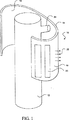
いま図1を参照すると、動脈瘤パッチ装置は10で示され、任意に、配送装置を含むが、該配送装置はカテーテル12に限定されない。パッチ14は、配置された状態又は予め決められた形状を図示する。パッチ14は、インターフェース表面16と、対向する非インターフェース表面18とを備える。一つの実施形態では、接着剤20が、インターフェース表面16に少なくとも部分的に配置されている。パッチ14は、多孔性又は非多孔性である可撓性材料で形成されて良く、メッシュのようなタイプの幾何学のステントを含んでも良い。ある実施形態では、1又はそれ以上の機械的密着装置22がインターフェース16に位置決めされ、動脈瘤が形成される血管壁に少なくとも位置決めされることになる。適当な機械的装置22は、真空のアプリケーションに限定されないが、低圧源、羽枝、鉤柄、ペンチ及び同様なものを含む。
【0024】
負圧が作用しているとき、接着デバイス22は、動脈瘤口を取り囲む血管壁の表面に押しつけられて動脈瘤口を固定する。パッチが多孔性であるとき、適合性のある形状が、インターフェース表面16と、動脈瘤口を取り囲む血管壁との間に望まれる。更に、多孔性パッチ14では、パッチ14の固有の弾性力が血管壁に接着装置22を押し付けるのに使用される。カテーテル12に結合されるバルーンに限定されないがそれを含む他の機械的装置は、インターフェース表面16及び密着装置22に圧力を加えるのに使用されうる。パッチ14は、内力を動脈瘤に隣接する血管の領域に提供する。この力は、熱エネルギ又は固有の機械的エネルギによって活性化され、及び/又は、パッチ14に加えることができる。解放可能なコネクタ24がパッチ14をカテーテル12に結合する。
【0025】
いま図2を参照すると、パッチ14は、動脈瘤の口に位置決めされるように構成されているアパーチャ(開口)26を含む。1つの実施形態では、コネクタ24は、カテーテルコネクタ24(a)及びパッチコネクタ24(b)とを含む。コネクタ24(a)及び24(b)は、カテーテルからパッチ14の機械的解放手段を与える。この機械的解放手段は、SMA要素とすることができる。あるいは、コネクタ24(a)及び24(b)は、起動状態で、パッチ14をカテーテルルーメンから切り離すデバイスであって、引っ張られたときに切断することができるようになったループ状のワイヤあるいは加熱されたワイヤを用いて2つのものを切断することができるデバイス、あるいは把持(キャッチ)のような機械的な解放手段である実際の組み立ジョイントとすることもできる。この場合、上記SMA要素は、体温よりも高い起動しきい値を有する。
【0026】
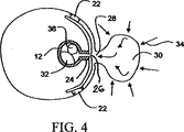
図3乃至5は、動脈瘤口28でのパッチ14の位置決め及びリリースを図示する。図3では、パッチ14は、しまい込まれた状態にあり、カテーテル12の外側に位置決めされている。他の実施形態では、パッチ14は、カテーテルの遠位端でカテーテルの内側に位置決めされて良い。しまい込まれた状態では、パッチ14の表面領域は、動脈瘤30の処理に関して動脈瘤口28へのアクセスを達成するのを最小にする。
【0027】
図4に図示したように、パッチ14は、その配置された状態又は予め決められた状態にある。アパーチャ26は、動脈瘤28に実質的にわたって位置決めされる。図4では、カテーテル12は、カテーテルルーメン32が、真空源に限定されないがそれを含む低圧力源に結合されるとき、動脈瘤30の排出を行うカテーテルルーメン32を有するように示す。動脈瘤30は、血管壁の残りの部分の圧力よりも低い。矢印で示したような圧力34が、動脈瘤30に加えられ、動脈瘤30の破裂を生じる可能性を作り出す。低圧源に対して動脈瘤30とカテーテルルーメン32とを結合することにより、動脈瘤30の排出が始まる。
【0028】
パッチ14は、NiTi、微小製造回路、微小製造センサ、及び微小製造トランスに限定されないがそれらを含むSMAを包含しうる。適当な微小製造センサは、圧力、温度、電気音響(electrosonic)、電圧、化学ポテンシャル及び電磁センサを含む。パッチ14は、2ウェイ形状メモリ効果の1ウェイを有することができる。
【0029】
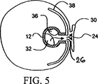
図5は、十分に潰れた動脈瘤30を示す。動脈瘤30が潰れた後、接着剤20は導入ルーメン36を介して導入され得る。36に結合された導入ルーメンは、接着剤20の源に結合されるか、又は、インターフェース表面16の接触位置で動脈瘤30を保持することができる有利な他の材料と結合する。シアノアクリレートのようなかかる接着剤は、当業者に知られている。
【0030】
接着剤20は、インターフェース表面16と血管壁の表面との間を占める体積である隙間領域40を部分的又は十分に満たすことができる。接着剤20は、血管壁とインターフェース表面16との間のいかなる不規則性も吸収することができる。
【0031】
接着剤20の使用は、インターフェース表面16と血管壁との間の関係を完全に又は部分的に包含することを任意に提供する。これを行い、これを適用すると、血管内の血液が圧力を加える。
【0032】
図6は、導入ルーメン36に結合された接着源42と、カテーテルルーメン32に結合された低圧源44とを図示する。
【0033】
以下の議論は、SMA材料又はバイモル圧電であるパッチ14に関する適当な材料に関係する。
【0034】
本発明の態様による2次元シート46の簡単な実施形態を図7に示す。ここで議論される基本的な概念は、後で記載する実際的な実施形態に直接適用されうる。この場合、シート46は、電気伝導性材料のグループから選択されたSMAから完全に作られる。最も一般的な例は、NiTi合金及びCuZnAl合金を含む。他の合金もまた使用可能である。加熱要素48の横方向の広がりに対するシート46の厚さの比は、シート46の一体性を維持しつつ、極力小さくするのが好ましい。
【0035】
SMAシート46は、さまざまな一般的な機械加工の手法によって製造される。たとえば、ウェハあるいは薄いプレート状の原料をローリングすることによって、棒状の原料から薄いウェハを分割することによって、又は同様な方法によって製造される。現在は、バーストックからの薄いウェハを分割するのが好ましい。
【0036】
SMA材料のウェハは、在来の帯鋸、コールドソー、環状ダイアモンド湿式鋸、又は、放電加工(EDM)、又は同様な方法を使用してバーストックからスライスされうる。結果のウェハは、平らな状態、及び、精確に所望の厚さに熱処理されうる。材料として保証されるSMAバルク特性は、バルクから直接得られる。
【0037】
シート46に含まれるSMA材料は、組み立てる前に前処理がなされるか、処理しないままにされている。この選択は、最終的な用途に依存する。
【0038】
複数の加熱要素48は、SMAシート46の頂部に位置決めされ、電気的絶縁層50によってシート46から絶縁される。シート46に電気的絶縁層50をラミネートすること、さもなければ堆積させることが最も便利である。電気的絶縁層50はまた、良好な熱伝導性であるのが好ましい。好ましい絶縁材料は、ポリイミド又は窒化シリコンSixNyを含む。電気的絶縁層50の厚さは、その横方向の広がりに対して小さくなるべきである。例えば、電気的絶縁層50は、十分な熱的な結合を保証し、加熱要素48とシート46との間の熱伝導を保証するために、2000Åの窒化シリコン層とすることができる。
【0039】
図7の簡単な実施形態では、加熱要素48は、薄膜レジスタの形態である。最も好ましくは、加熱要素48は、オーミックヒータ、若しくは、電流を熱エネルギに変換することができる他の同様な装置である。それらは、TiW又はTaOのような在来の抵抗材料を含む。好都合なことに、抵抗材料は、最初に層50に堆積され、周知のVLSI又はマイクロマシーン技術によってパターニングされる。次いで、加熱要素48は型取られ、又は、さもなければ周知の技術によって形成される。
【0040】
図9では、シートSMA46の厚さは、Sによって示される。明確のために、特定の加熱要素48Xは、本発明の詳細を説明するのに選択されている。加熱要素48Xは、SMAシート46の隣接する部分52Xと関係している。示したように、加熱要素48Xは、同様に電気的絶縁層50の部分54Xと関係している。部分52Xは、加熱要素48Xの直接下に配置されている。部分52Xの幅は、Dによって示される。示したように、加熱要素48Xは、熱を部分52Xに排他的に提供する。熱は部分54Xを介して、SMAシート46の局所部分を示す部分52Xに伝搬する。
【0041】
簡単な実施形態の作動は、図7と図8との比較によって最も良く理解される。
【0042】
この場合、SMA材料は、活性しきい値温度まで熱的に活性化されたとき、所定の形状を保証するために予め連続にされている。図7では、SMAシート46は、不活性な状態で示されている。
【0043】
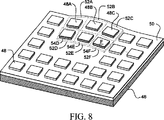
図8は、48A乃至12Fとして名付けられた6つの加熱要素48が熱を与える特別なケースを示す。それ故、熱は、絶縁層50の部分54A乃至18Fを横断し、SMAシート46の隣接部分52A乃至16Fを活性しきい値に到達させる。その結果、52A乃至16Fの部分は、良好に決められた形状を保証し、プロセスでは、通常の活性力を提供する。示したように、局所的変形は、上向きの凸状である。いったん部分52A乃至16Fがそれらの形状を保証するので、それらの位置を取り囲むシート46の領域は、所定の形状特性によって変形する。
【0044】
実際に、全体のシート46は、その幾何学によって指示されたような局所変化のために、結果の形状を保証する。図8の簡単な場合では、シート46の残りが、フラットを残し、若しくは、さもなければ、それを自然の形状に戻す(自然とは、その不活性状態を意味する)。より複雑な結果の形状を、後の実施形態で記載する。
【0045】
加熱プロセス及び、部分52と隣接することによって想定される形状の背後の原理を、図10Aに最良に図示する。我々は、1つの加熱要素48Xを考慮する。
【0046】
明確のために、加熱の際に、部分52Xに隣接することによって想定される所定の形状は示されていない。Wによってその幅が示された要素48Xによって生成された熱は、絶縁層50を介して矢印に沿って進む。特に、熱エネルギは、層50の部分54Xを横切る。層50は、左右の幅に対して非常に比例して薄く、従って、部分54Xは、熱を容易にシート46に伝達する。いったんシート46に入ったならば、熱は部分52Xに隣接して全体に広がる。
【0047】
グラフ10Bは、ヒータ48Xの下の任意の固定された深さでの温度分布を示す。図10Bのグラフは、部分52X内部の、X方向における、側方の温度分布を示す。要素48Xの直下では、温度は、-W/2から+W/2までのカーブの水平な部分によって示されるように、最大で保持されている。言い換えれば、部分52Xに導かれる熱は、他の部分52、即ち部分52Yには広がらない。その代わり、熱は、他の部分52に達する前に、シート46の外に矢印Rに沿って放射する。
【0048】
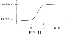
既に述べたように、隣接部分52の形状は、予め列にされた形状のSMA又はこれらの領域のシート46に依存する。また、形状は、部分52に維持された温度に依存する。部分52の温度が、SMA材料がオーステナイト状態に達する臨界温度と等しいか、より高くなるとき、予め列状にされた形状との完全な一致が達成される。これは、図11のグラフに示した最高のものである。T1より下の温度では、SMA材料は、マルテンサイト特性によって示されたような柔軟さを維持する。それ故、T1で又はT1より下に保持された部分52は、取り囲むことによってそれらに与えられた形状に従う。オーステナイト状態への変化は、温度T1とT2の間で生じる。部分52が、この温度範囲で保持されるとき、それらは、リラックスした形態と予め列状の形態との間の中間の形状を保証する。従って、慎重な熱調整によって、連続的な仕方でシート46のいかなる部分52の形状を変化させることができる。
【0049】
加熱要素48が、それらの間に置かれた層50だけでシート46に直接取り付けれているシート46の全体の構造は、非常に簡単である。組立プロセスは簡単であり、低コストである。
【0050】
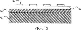
本発明の他の実施形態を図12に示す。ここで、SMA材料の2次元シート56が、被覆層58に配置されている。この場合、層58は、機械的安定性を提供するために十分に厚い。
【0051】
薄い絶縁層60が、加熱要素62とシート56との間に電気的絶縁を提供するためにシート56の頂部に配置されている。層60は十分に薄く、要素62からシート56までの熱の自由な流れを制限するために適当な熱特性を有する。この実施形態では、シート56のSMA材料はまた、電気伝導性である(即ち、TiNi合金又はCuZuAl合金)。
【0052】
この実施形態の作動は、第1の実施形態の作動と類似している。シート56の全ての部分がマルテンサイト状態であるとき、被覆層58の追加された安定性は、良く構成された形状との一致を保証する。
【0053】
図13の実施形態は、基板として作用する被覆層68を備える電気伝導性SMAのシート56を示す。この場合、不利な影響からシートを保護するために化学的に不活性で安定である材料から選択される。
【0054】
加熱要素62とシート56との間の電気的絶縁は、要素64の下の点別(point-wise)堆積の電気絶縁セクション64の部分によって提供される。かかる構造は、絶縁材料の層及び加熱材料の層を最初に適用することによって提供されうる。次いで、要素62及び対応する電気絶縁セクション64は、エッチング又は他の周知のプロセスによって作り出される。好ましくは、周知のVLSI技術又はマイクロマシーン技術はこの目的のために採用される。
【0055】
図14は、2次元シート70が電気的絶縁SMA材料によって作られる他の実施形態を示す。この構成では、絶縁は必要ない。従って、加熱要素62は、シート70に直接取り付けられる。基板として作用する被覆層68が、機械的安定性及び抵抗を与えるためにいったん再び提供される。層68がまた、シート70からの熱の消散を助けるために良好な熱伝導であるのが好ましい。
【0056】
図12乃至14の実施形態は全て、上で説明した仕方で作動する。紹介した変更は、1セットの技術要求を与える適当な構造を選択する際に当業者を助ける。
【0057】
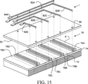
好ましい実施形態を図15に示す。好ましくはNiTi合金である電気伝導性SMA材料の2次元シート72が絶縁層74で被覆されている。好ましくは、層74は、SixNy又はポリイミドでできており、熱を容易に伝えるように十分に薄い。
【0058】
型どられた加熱要素76を、層74に配置する。要素76は、層74の頂部にTiW又はTaOを最初にスパッタリングすることによって得られ、次いで、パターニングステップを実行する。加熱要素76は、非常に高い抵抗を提供する。
【0059】
好ましい実施形態では、要素76はジグザグ形状を有する。このことは、活性なとき、シート72により良い熱分布を保証する。
【0060】
第2の絶縁層80を、要素76及び層74の頂部に提供する。好ましくは、層80は、ポリイミドのような可撓性電気的絶縁体からなり、それは要素76及び74の上にスピンコートされうる。要素76と電気的に接触することを許容するために、多数の貫通穴86が層80に開けられる。穴86は、要素76のターミナル部分と目立つほどに配列される。
【0061】
接触ライン82のセットが、層80の頂部に型取られる。好ましくは、接触ライン82は、金のような可撓性で高伝導性材料で作られる。ライン82は、パターニング又は他の適当な技術によって構成されうる。共通のリターンライン82Aは、全ての要素76の左のターミナルで電気的接触を提供するように置かれる。リターンライン82Aは、層80の頂部の表面積を節約し、全ての要素76が、連続的な基礎に同時にアドレスされない限り望ましい。連続活性化が要求されるならば、追加の全幅層はリターンパスに関して捧げられ得る。他のライン82B乃至42Eは、それぞれ要素76の右のターミナルと電気的に接触している。
【0062】
外部の電気的接触は、ライン82A乃至42Eに対応する接触パッド84A乃至84Eでなされる。この目的のために、パッド84A乃至84Eは、ライン82A乃至42Eよりもかなり厚く設計される。実際の電気的接触は、ワイヤボンディング又は同様な手段でなされる。
【0063】
いったんシート72の全体の構造が組み立てられたなら、SMAは、周知の方法を使用して結果の形状を保証するために付勢シート72によって「慣らされる(trained)」。例えば、シート72は、マンドレルに形成され、クランプで適所に固定される。次いで、全体の固定物がアニーリング炉に配置され、好ましくは、おおよそ450℃で約30分、不活性ガスで浄化する。冷却の際、フィルムがマンドレルから剥離される。このとき、シート72は操作できる。
【0064】
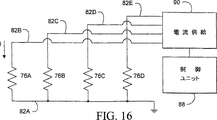
好ましい実施形態の電気的接触を示す電気回路図を図16に示す。制御ユニット88が、電流供給装置90に接続される。好ましくは、ユニット88及び供給装置90の両方は、シート72から離れて配置される。ユニット88は、好ましくは、要素76の所望の組み合わせを選択することができるマイクロプロセッサである。電流供給装置90は、電流を要素76の選択された組み合わせに導くことができる調節可能なソースであるのが好ましい。ライン82A乃至42Eは、供給装置90に直接接続される。要素76A乃至76Dを抵抗として示す。リターンライン82Aは接地される。
【0065】
作動中、制御ユニット88は、活性化すべき要素76の組み合わせを選択する。次いで、それは対応するコマンドを供給装置90に送る。供給装置90は、選択された組み合わせの要素76に電流を導くことによって応答する。例えば、要素76A及び76Dが選択される。電流は、要素76A及び76Dに導かれ、対応する隣接部分78A及び78Dは、良く構成された形状を呈する。電流が十分大きく、隣接部分78A及び78Dで維持される温度がT2より上ならば(図15参照)、部分78A及び78Dはそれらの予めしつけられた形状を呈する。温度がT1とT2との間であるならば、部分78A及び78Dは中間の形状を呈する。供給装置90が調整可能であるので、適当な電流が作動中、及び実験に基づいて調節されて選択されうる。従って、部分78A及び78Dの形状は必要に応じて変化しうる。
【0066】
隣接部分78C及び78Dが選択されるとき、図17は、シート72の結果の形状を図示する。SMAが、その全体の長さに沿って情報に湾曲するように予め連続されていることが想定される。従って、一緒に、部分78C及び78Dの逸れは、より大きな全部の逸れに寄与する。部分78B乃至39Dが加熱され、SMAがS型になるように予め慣らされるとき、図18は、層72の別の可能性の結果の形状を図示する。記述の全体にわたって、シート72のSMAが、組立の前又は後で連続にされることが理解できる。組立の前のトレイン(慣らし)は、SMAと一緒にトレイン(慣らし)されるならば、即ち、高アニーリング温度で行うならば損傷しうる材料で作動するときに好ましい。
【0067】
好ましい実施形態に類似する別の実施形態では、シート72は、図20に示したような被覆層92を有する。より良い理解のために、シート72の逸れを示す。歪センサ94を、層92に配置する。センサ92は、環状歪センサ、歪ゲージのような拡張歪センサ、又は、ベンドセンサのいずれであっても良い。ベンドセンサが、曲げ応力を測定するために配置された歪ゲージであり、かくして、環状歪みである。これらの全ての装置は、従来技術で周知である。この場合、センサ94は、これらの要素76に対応する位置に配置される。幾何学に基づいて、異なる配置の適用は好ましい。
【0068】
センサ94を備える電気回路図を図19に示す。点線はシート72に取り付けられた要素を示す。要素76A乃至38Dに対する接続が同様に維持されているのに対して、全てのセンサ94A乃至94Dは、ライン96A乃至96Dを介して制御ユニット88にそれぞれ結線される。この仕方では、ユニット88は、センサ94A乃至94Dのうちの各一つから個別に局所歪を表す信号を受けることができる。形状記憶98はユニット88に接続される。メモリは、センサ94から導き出された情報に基づいてシート72の結果の形状をマッピングすることができる。
【0069】
好ましくは、メモリ98は、要素76の知られた組み合わせによって作り出された結果の形状のインベントリーを有する。言い換えれば、メモリ98は、マッピングされた結果の形状の位置をリコールし、新しいものをストアすることができる。最も好ましい実施形態では、メモリ98はまた、隣接する部分の中間形状に対応する実際の電流値をストアすることができる。このことは、作動中、形状がリコールされ、且つ、随意にストアされうることを意味する。従って、実施形態は、いかなるデバイス用途、即ち、カテーテルのガイドのように、非常に多目的且つ実用的である。
【0070】
図21は、センサ94が要素76の間に配置されたことだけが上と異なる更に別の実施形態を示す。図22は、温度センサ100が要素76の間に取り付けられた別の変形を示す。これは、シート72の温度を監視するために有利である。
【0071】
特に好ましい実施形態では、このデータはメモリ98にストアされる。作動中にセンサ100からの温度をチェックすることは、オーバーヒート及び他の関連する機能不全を防止する。勿論、1つ以上の熱センサ100が提供されうる。理想的には、多数のかかるセンサ100が提供されうる。理想的には、多数のかかるセンサ100は、シート72に任意に位置決めされる。
【0072】
図23は、被覆層102の頂部で含まれたマルテンサイト状態の、図20の実施形態を示す。層102は、特に損傷環境要因、即ち、腐食環境から電気接続及び要素76を保護するために適用される。
【0073】
図24及び図25は、SMAの2次元シート104が冷却されうる2つの方法を示す。簡単のために、加熱要素108を除く全ての他の要素を省いてある。図24では、冷却要素は、シート104と直接接触するフィンのセットである。この配置は、効果的な熱伝導及び消散を保証する。同様に、構造id図25は、ダクト112(図示せず)を備える基板層110を使用して熱を効果的に消費する。ダクト112は、冷却液、即ち、水を運び、浪費熱エネルギを吸収し、運び去る。
【0074】
本発明を、最も実用的且つ好ましい実施形態を考慮して記載したけれども、本発明が開示の実施形態に限定されないのは理解されるべきであるが、逆に、種々の修正、及び、添付した請求の範囲の精神及び範囲内に含まれる均等の範囲をカバーする。例えば、ペルチェデバイスがまた、熱消散に対する等しい解を提供し得る。それ故、当業者は、かかる全ての均等な構造が以下の請求の範囲の範囲内に含まれうることを理解すべきである。
【図面の簡単な説明】
【図1】図1は、本発明の動脈瘤パッチ装置の斜視図である。
【図2】図2は、動脈瘤に隣接して位置決めされた図1のパッチの断面図である。
【図3】図3は、パッチがしまい込み位置にあるとき、カテーテルの外側表面に位置決めされたパッチの断面図である。
【図4】図4は、配置位置におけるパッチ、及び、カテーテルに形成されたルーメンを介する動脈瘤の排出の断面図である。
【図5】図5は、配置された/予め決められた形状位置におけるパッチ、接着剤の導入、及び、動脈瘤の潰れの断面図である。
【図6】図6は、カテーテルの遠位端で位置決めされたしまい込まれたパッチの断面図である。
【図7】図7は、本発明による非活性化2次元シートの等角図である。
【図8】図8は、活性化状態における図7の2次元シートの等角図である。
【図9】図9は、図7の2次元シートの一部の等角図である。
【図10A】図10Aは、図10Aの2次元の一部の断面図である。
【図10B】図10Bは、図10Aの一部における温度分布のグラフである。
【図11】図11は、温度の関数としての、マルテンサイトとオーステナイトの間の遷移のグラフである。
【図12】図12は、絶縁層及び被覆層を備える2次元シートの断面図である。
【図13】図13は、点別(point-wise)絶縁層及び被覆層を備える2次元シートの断面図である。
【図14】図14は、被覆層を備える2次元シートの断面図である。
【図15】図15は、本発明による2次元シート及び能動要素の組立を図示する分解図である。
【図16】図16は、能動機構の等価回路を示す図である。
【図17】図17は、本発明による2次元シートの歪を図示する側面図である。
【図18】図18は、本発明の一態様によるシートの複雑なプレトレイン形状を図示する斜視図である。
【図19】図19は、歪センサを使用する実施形態の等価回路を示す図である。
【図20】図20は、歪センサを備える2次元シートの断面図である。
【図21】図21は、加熱要素のそばに取り付けられた歪センサを備える2次元シートの断面図である。
【図22】図22は、温度センサを備える2次元シートを示す断面図である。
【図23】図23は、摂食(eating)要素にわたって適用される保護被覆を備える2次元シートの断面図である。
【図24】図24は、熱消散のための羽を使用する2次元シートの断面図である。
【図25】図25は、熱消散のための水ダクトを使用する2次元シートの断面図である。[0001]
(Cross-reference of related applications)
This application is a continuation-in-part of serial number 08 / 708,586, named “DISTRIBUTED ACTIVATOR FOR A TWO-DIMENSIONAL SHAPE MEMORY ALLOY” filed by Ronald S. Maynard on September 5, 1996. As a reference.
[0002]
(Field of Invention)
This application relates to a method and apparatus for treating an aneurysm, and more particularly to a patch for treating an aneurysm configured to form a cohesion between the patch and a vessel wall adjacent to the aneurysm mouth. Adhesion maintains a fixed position of the patch with respect to the aneurysm mouth.
[0003]
(background)
There are a variety of devices used for aneurysm repair. U.S. Pat.No. 4,512,238 restores transluminal repair and patency of debilitated or damaged blood vessels using a shape memory nitinol wire previously inserted into a blood vessel requiring repair Disclosed is an apparatus. When placed in the body and the insulation is removed, the wire warms and returns to a pre-selected coiled shape to support the vessel wall. One problem with this device is that the task of adding a sleeve to the wire support is difficult because the wire is many times longer than the sleeve when it is inserted.
[0004]
U.S. Pat. No. 4,140,126 discloses another device for treating an aneurysm. The device is attached to the outside of the carrier catheter and is positioned in the vessel in a collapsed configuration that is smaller than the vessel diameter. The device is then expanded into the vessel wall by use of a separate mechanical dilator that is controlled by the user from outside the body.
[0005]
U.S. Pat. No. 4,787,899 describes a system for positioning an implant within a body lumen. The graft is packed into a guide inserted into the lumen. An inflatable balloon is used to secure the distal end of the graft to the lumen wall. The guide is then pushed upstream to draw the folded graft out of the guide and into the lumen wall where the staple ends secure it within the lumen wall. One problem with this device is that the balloon providing the anchor for the distal end of the graft while the guide is moving upstream is sufficient for the vessel wall to prevent misalignment of the graft. Does not provide the right pressure.
[0006]
It would be desirable to provide an aneurysm patch that does not have a coil shape and adheres closely to the vessel wall adjacent to the aneurysm's mouth. It is further desirable to provide an aneurysm patch having a non-electrically activated deployment that can be positioned adjacent to the aneurysm's mouth. Moreover, it would be further desirable to provide an aneurysm patch having an electrically activated deployment that is configured to be positioned adjacent to the aneurysm's mouth.
[0007]
(wrap up)
It is an object of the present invention to provide a method and apparatus for treating an aneurysm.
[0008]
Another object of the present invention is to provide an aneurysm patch positioned over the aneurysm mouth.
[0009]
Yet another object of the present invention is to provide an aneurysm patch having a non-electrical placement positioned over the aneurysm mouth.
[0010]
Yet another object of the present invention is to provide an aneurysm patch that is introduced into a blood vessel in a collapsed state and positioned over the aneurysm's mouth in a deployed state.
[0011]
It is a further object of the present invention to provide an aneurysm patch comprising a vascular interface side that includes a plurality of anchor elements.
[0012]
Yet another object of the present invention is to provide an aneurysm patch that forms a mechanical adhesion between the patch and the vessel wall adjacent to the aneurysm mouth.
[0013]
Yet another object of the present invention is to provide an aneurysm patch comprising an aperture configured to be coupled to a low pressure source.
[0014]
Another object of the present invention is to provide an aneurysm patch comprising at least an internal pressure and a material having a predetermined shape, the internal pressure being reduced from a stowed state to a predetermined state. Move.
[0015]
Yet another object of the present invention is to provide an aneurysm patch formed from a thermally active material that, when electrically heated, moves into a predetermined shape.
[0016]
It is a further object of the present invention to provide an aneurysm patch consisting of SMA elements with an activation threshold above body temperature.
[0017]
These and other objects of the present invention achieved with an aneurysm patch device for treating an aneurysm formed in a blood vessel include a patch comprising a vascular interface side and an opposing non-interface side. The patch is sufficiently flexible to provide a patch stowed state when the patch is delivered via a blood vessel and a patch placement state when the patch is at least partially positioned over the aneurysm's mouth. It is made of sex material. The interface side of the patch is configured to form a cohesion between the patch and the region of the vessel wall adjacent to the aneurysm mouth. The close contact maintains a fixed position of the patch relative to the aneurysm mouth.
[0018]
In certain embodiments of the invention, the patch includes a vascular interface side and an opposing non-interface side, and the patch is configured to have a stowed condition when delivered to the aneurysm mouth. The patch is formed from a thermally activated material that moves into a predetermined shape when electrically heated. The predetermined shape forms a close contact between the blood vessel interface side and the region of the blood vessel that is all adjacent to the aneurysm mouth. The close contact maintains the fixed position of the patch relative to the aneurysm mouth.
[0019]
Detailed Description of Preferred Embodiments
The present invention provides an aneurysm patch device for treating an aneurysm formed in a blood vessel including a patch comprising a vascular interface side and an opposing non-interface side. The patch forms a flexible material sufficient to provide a patch stowage when the patch is delivered via a blood vessel and a patch placement with the patch at least partially positioned over the mouth of the aneurysm To do. The interface side of the patch is configured to form a tight or bonded state between the patch and the region of the vessel wall adjacent to the aneurysm mouth. The adhesion state maintains the fixed position of the patch relative to the aneurysm mouth.
[0020]
In one embodiment of the present invention, the patch is assumed to be passively placed and is not electrically activated. In other embodiments of the invention, the patch is formed of a thermally active material that moves to a predetermined shape when electrically heated. The pre-determined shape / arrangement creates an adhesion between the vascular interface side and the region of the vessel wall adjacent to the aneurysm mouth.
[0021]
In a pre-determined shape / arrangement, the patch has a circumference of less than 360 degrees, more preferably less than 240 degrees, and even more preferably less than 180 degrees. In a pre-determined shape / arrangement, the patch can have an interface side that substantially matches the geometry (having curvature) to the adjacent vessel wall.
[0022]
Passive activation of the patch is achieved with the elasticity inherent in the patch. This resilience can then drive one or more contact devices within the walls of the blood vessel surrounding the aneurysm. Adhesion is achieved either by selecting materials for an internally resilient patch including SMA and bimorph piezoelectric, or with an adhesive device positioned on the interface surface of the patch to the vessel wall. Adhesion is non-friction.
[0023]
Referring now to FIG. 1, an aneurysm patch device is shown at 10 and optionally includes a delivery device, but the delivery device is not limited to the
[0024]
When negative pressure is acting, the
[0025]
Referring now to FIG. 2, the
[0026]
FIGS. 3-5 illustrate the positioning and release of the
[0027]
As shown in FIG. 4, the
[0028]
[0029]
FIG. 5 shows a fully collapsed
[0030]
The adhesive 20 can partially or fully fill the gap region 40, which is the volume that occupies between the
[0031]
The use of adhesive 20 optionally provides complete or partial inclusion of the relationship between
[0032]
FIG. 6 illustrates an
[0033]
The following discussion relates to a suitable material for the
[0034]
Figure 3 illustrates a simple embodiment of a two-
[0035]
The
[0036]
SMA material wafers can be sliced from bar stock using conventional band saws, cold saws, annular diamond wet saws, or electrical discharge machining (EDM), or similar methods. The resulting wafer can be heat treated to a flat state and precisely to the desired thickness. The SMA bulk properties guaranteed as material are obtained directly from the bulk.
[0037]
The SMA material contained in the
[0038]
A plurality of
[0039]
Figure 7 In a simple embodiment, the
[0040]
Figure 9 Now, the thickness of the
[0041]
The operation of a simple embodiment is illustrated in FIG. 7 And figure 8 And is best understood by comparison.
[0042]
In this case, the SMA material is previously continuous to ensure a predetermined shape when thermally activated to the activation threshold temperature. Figure 7 The
[0043]
Figure 8 Shows a special case where six
[0044]
In fact, the
[0045]
The heating process and the principle behind the shape assumed by being adjacent to part 52 10 A is best illustrated. We consider one
[0046]
For clarity, the predetermined shape assumed by adjacent to the
[0047]
Graph 10 B shows the temperature distribution at any fixed depth below the
[0048]
As already mentioned, the shape of the adjoining portion 52 depends on the pre-row shaped SMA or the
[0049]
The overall structure of the
[0050]
FIG. 4 shows another embodiment of the present invention. 12 Shown in Here, a two-
[0051]
A thin insulating
[0052]
The operation of this embodiment is similar to that of the first embodiment. When all parts of the
[0053]
Figure 13 The embodiment shows a
[0054]
Electrical insulation between the
[0055]
Figure 14 Shows another embodiment in which the two-
[0056]
Figure 12 Thru 14 All of the embodiments operate in the manner described above. The introduced changes assist one skilled in the art in selecting an appropriate structure that provides a set of technical requirements.
[0057]
Preferred embodiment diagram 15 Shown in A two-
[0058]
A shaped
[0059]
In a preferred embodiment,
[0060]
A second insulating
[0061]
A set of contact lines 82 is cast on top of the
[0062]
External electrical contact is made with
[0063]
Once the entire structure of the
[0064]
Schematic diagram showing electrical contact of a
[0065]
In operation, the
[0066]
When
[0067]
In another embodiment similar to the preferred embodiment, the
[0068]
Diagram of electrical circuit with sensor 94 19 Shown in Dotted lines indicate elements attached to the
[0069]
Preferably,
[0070]
Figure 21 Shows yet another embodiment that differs from the above only in that the sensor 94 is disposed between the
[0071]
In a particularly preferred embodiment, this data is stored in
[0072]
Figure 23 Is the martensitic state contained at the top of the
[0073]
Figure 24 And figure 25 Shows two ways in which the two-
[0074]
Although the present invention has been described in view of the most practical and preferred embodiments, it should be understood that the invention is not limited to the disclosed embodiments, but conversely, various modifications and attachments have been made. Covers the spirit and scope of the claims and equivalent scope. For example, a Peltier device may also provide an equal solution for heat dissipation. Therefore, those skilled in the art should understand that all such equivalent structures may be included within the scope of the following claims.
[Brief description of the drawings]
FIG. 1 is a perspective view of an aneurysm patch device of the present invention.
FIG. 2 is a cross-sectional view of the patch of FIG. 1 positioned adjacent to the aneurysm.
FIG. 3 is a cross-sectional view of the patch positioned on the outer surface of the catheter when the patch is in the retracted position.
FIG. 4 is a cross-sectional view of aneurysm drainage through a patch and a lumen formed in a catheter in the deployed position.
FIG. 5 is a cross-sectional view of a patch, adhesive introduction, and aneurysm collapse in a deployed / predetermined shape position.
FIG. 6 is a cross-sectional view of a stowed patch positioned at the distal end of the catheter.
FIG. 7 is an isometric view of a deactivated two-dimensional sheet according to the present invention.
FIG. 8 is an isometric view of the two-dimensional sheet of FIG. 7 in an activated state.
FIG. 9 is an isometric view of a portion of the two-dimensional sheet of FIG.
10A is a cross-sectional view of a two-dimensional portion of FIG. 10A.
FIG. 10B is a graph of temperature distribution in a part of FIG. 10A.
FIG. 11 is a graph of the transition between martensite and austenite as a function of temperature.
FIG. 12 is a cross-sectional view of a two-dimensional sheet including an insulating layer and a covering layer.
FIG. 13 is a cross-sectional view of a two-dimensional sheet comprising a point-wise insulating layer and a covering layer.
FIG. 14 is a cross-sectional view of a two-dimensional sheet including a coating layer.
FIG. 15 is an exploded view illustrating the assembly of a two-dimensional sheet and active element according to the present invention.
FIG. 16 is a diagram illustrating an equivalent circuit of an active mechanism.
FIG. 17 is a side view illustrating distortion of a two-dimensional sheet according to the present invention.
FIG. 18 is a perspective view illustrating a complex pre-train shape of a seat according to one aspect of the present invention.
FIG. 19 is a diagram illustrating an equivalent circuit of an embodiment using a strain sensor.
FIG. 20 is a cross-sectional view of a two-dimensional sheet including a strain sensor.
FIG. 21 is a cross-sectional view of a two-dimensional sheet comprising a strain sensor attached by a heating element.
FIG. 22 is a cross-sectional view showing a two-dimensional sheet including a temperature sensor.
FIG. 23 is a cross-sectional view of a two-dimensional sheet with a protective coating applied over an eating element.
FIG. 24 is a cross-sectional view of a two-dimensional sheet using wings for heat dissipation.
FIG. 25 is a cross-sectional view of a two-dimensional sheet using a water duct for heat dissipation.
Claims (33)
動脈瘤パッチ(14)と挿入ツール(12)とを有し、
前記動脈瘤パッチは層状の形態であり、ほぼ環状の巻き上げ状態と前記パッチが非環状の配置状態とを有しており、
前記動脈瘤パッチは着脱可能に前記挿入ツールに装着されており、前記挿入ツールは前記動脈瘤パッチを装着するための装着手段(24b)を有しており、
前記装着手段(24b)が前記動脈瘤パッチの縁部から離れた前記パッチの部分に位置していることを特徴とする、装置。An aneurysm patch device (10) for treating an aneurysm formed in a blood vessel, comprising:
An aneurysm patch (14) and an insertion tool (12);
The aneurysm patch is in the form of a layer, and has a substantially annular roll-up state and a non-annular arrangement state of the patch,
The aneurysm patch is detachably attached to the insertion tool, and the insertion tool has attachment means (24b) for attaching the aneurysm patch,
Device, characterized in that the mounting means (24b) are located in the part of the patch remote from the edge of the aneurysm patch.
前記装着手段(24b)が前記動脈瘤パッチ状の縁部から離れたパッチの領域に位置していることを特徴とする上記請求項1ないし22のいずれか1つの請求項に記載された装置に使用する動脈瘤パッチ。The patch has a flexible layered patch member (14) movable from a substantially annular winding position to a non-annular arrangement, the patch facing the vascular interface side (16). A non-interface side (18) and attachment means (24b) for releasably attaching the aneurysm patch to the insertion tool (12);
23. A device according to any one of the preceding claims, characterized in that the mounting means (24b) are located in the area of the patch remote from the edge of the aneurysm patch. Aneurysm patch to use.
Applications Claiming Priority (3)
| Application Number | Priority Date | Filing Date | Title |
|---|---|---|---|
| US08/756,099 | 1996-11-25 | ||
| US08/756,099 US5941249A (en) | 1996-09-05 | 1996-11-25 | Distributed activator for a two-dimensional shape memory alloy |
| PCT/US1997/019392 WO1998023227A1 (en) | 1996-11-25 | 1997-10-29 | Aneurysm patch apparatus and method for treating an aneurysm |
Publications (3)
| Publication Number | Publication Date |
|---|---|
| JP2001505109A JP2001505109A (en) | 2001-04-17 |
| JP2001505109A5 JP2001505109A5 (en) | 2005-07-14 |
| JP4142108B2 true JP4142108B2 (en) | 2008-08-27 |
Family
ID=25042042
Family Applications (1)
| Application Number | Title | Priority Date | Filing Date |
|---|---|---|---|
| JP52465098A Expired - Fee Related JP4142108B2 (en) | 1996-11-25 | 1997-10-29 | Aneurysm patch device |
Country Status (8)
| Country | Link |
|---|---|
| US (2) | US5941249A (en) |
| EP (1) | EP0957823B1 (en) |
| JP (1) | JP4142108B2 (en) |
| AT (1) | ATE298543T1 (en) |
| AU (1) | AU5151298A (en) |
| CA (1) | CA2272655C (en) |
| DE (1) | DE69733667T2 (en) |
| WO (1) | WO1998023227A1 (en) |
Families Citing this family (157)
| Publication number | Priority date | Publication date | Assignee | Title |
|---|---|---|---|---|
| US20030036746A1 (en) | 2001-08-16 | 2003-02-20 | Avi Penner | Devices for intrabody delivery of molecules and systems and methods utilizing same |
| US6475170B1 (en) * | 1997-12-30 | 2002-11-05 | Remon Medical Technologies Ltd | Acoustic biosensor for monitoring physiological conditions in a body implantation site |
| US7128073B1 (en) | 1998-11-06 | 2006-10-31 | Ev3 Endovascular, Inc. | Method and device for left atrial appendage occlusion |
| US7044134B2 (en) | 1999-11-08 | 2006-05-16 | Ev3 Sunnyvale, Inc | Method of implanting a device in the left atrial appendage |
| US20020169473A1 (en) | 1999-06-02 | 2002-11-14 | Concentric Medical, Inc. | Devices and methods for treating vascular malformations |
| US6375668B1 (en) | 1999-06-02 | 2002-04-23 | Hanson S. Gifford | Devices and methods for treating vascular malformations |
| US6231561B1 (en) | 1999-09-20 | 2001-05-15 | Appriva Medical, Inc. | Method and apparatus for closing a body lumen |
| US6551303B1 (en) | 1999-10-27 | 2003-04-22 | Atritech, Inc. | Barrier device for ostium of left atrial appendage |
| US6689150B1 (en) | 1999-10-27 | 2004-02-10 | Atritech, Inc. | Filter apparatus for ostium of left atrial appendage |
| US6652555B1 (en) | 1999-10-27 | 2003-11-25 | Atritech, Inc. | Barrier device for covering the ostium of left atrial appendage |
| US6994092B2 (en) * | 1999-11-08 | 2006-02-07 | Ev3 Sunnyvale, Inc. | Device for containing embolic material in the LAA having a plurality of tissue retention structures |
| US8298257B2 (en) | 2000-06-29 | 2012-10-30 | Concentric Medical, Inc. | Systems, methods and devices for removing obstructions from a blood vessel |
| US6730104B1 (en) | 2000-06-29 | 2004-05-04 | Concentric Medical, Inc. | Methods and devices for removing an obstruction from a blood vessel |
| AU2001285078A1 (en) * | 2000-08-18 | 2002-03-04 | Atritech, Inc. | Expandable implant devices for filtering blood flow from atrial appendages |
| US7169164B2 (en) | 2000-09-21 | 2007-01-30 | Atritech, Inc. | Apparatus for implanting devices in atrial appendages |
| CN1529571A (en) * | 2001-03-08 | 2004-09-15 | ̩ | Atrial filter implants |
| US6941169B2 (en) * | 2001-06-04 | 2005-09-06 | Albert Einstein Healthcare Network | Cardiac stimulating apparatus having a blood clot filter and atrial pacer |
| US7011671B2 (en) * | 2001-07-18 | 2006-03-14 | Atritech, Inc. | Cardiac implant device tether system and method |
| US8715312B2 (en) | 2001-07-20 | 2014-05-06 | Microvention, Inc. | Aneurysm treatment device and method of use |
| US7572288B2 (en) * | 2001-07-20 | 2009-08-11 | Microvention, Inc. | Aneurysm treatment device and method of use |
| US8252040B2 (en) | 2001-07-20 | 2012-08-28 | Microvention, Inc. | Aneurysm treatment device and method of use |
| US7669799B2 (en) * | 2001-08-24 | 2010-03-02 | University Of Virginia Patent Foundation | Reversible shape memory multifunctional structural designs and method of using and making the same |
| WO2003063732A2 (en) | 2002-01-25 | 2003-08-07 | Atritech, Inc. | Atrial appendage blood filtration systems |
| CA2487934A1 (en) * | 2002-05-30 | 2003-12-11 | University Of Virginia Patent Foundation | Active energy absorbing cellular metals and method of manufacturing and using the same |
| US8075585B2 (en) * | 2002-08-29 | 2011-12-13 | Stryker Corporation | Device and method for treatment of a vascular defect |
| US7658709B2 (en) * | 2003-04-09 | 2010-02-09 | Medtronic, Inc. | Shape memory alloy actuators |
| US6832478B2 (en) * | 2003-04-09 | 2004-12-21 | Medtronic, Inc. | Shape memory alloy actuators |
| WO2004110740A1 (en) * | 2003-05-28 | 2004-12-23 | University Of Virginia Patent Foundation | Re- entrant cellular multifunctional structure for energy absorption and method of manufacturing and using the same |
| US7632291B2 (en) | 2003-06-13 | 2009-12-15 | Trivascular2, Inc. | Inflatable implant |
| US20040260384A1 (en) | 2003-06-17 | 2004-12-23 | Medtronic Ave | Superelastic coiled stent |
| US6979050B2 (en) * | 2003-12-04 | 2005-12-27 | General Motors Corporation | Airflow control devices based on active materials |
| US7118652B2 (en) * | 2003-12-04 | 2006-10-10 | General Motors Corporation | Airflow control devices based on active materials |
| US7059664B2 (en) * | 2003-12-04 | 2006-06-13 | General Motors Corporation | Airflow control devices based on active materials |
| WO2005069996A2 (en) * | 2004-01-02 | 2005-08-04 | Js Vascular Inc. | Monocusp valve construction and defect closure device for deep vein regurgitation |
| US8992592B2 (en) * | 2004-12-29 | 2015-03-31 | Boston Scientific Scimed, Inc. | Medical devices including metallic films |
| US7901447B2 (en) * | 2004-12-29 | 2011-03-08 | Boston Scientific Scimed, Inc. | Medical devices including a metallic film and at least one filament |
| US8998973B2 (en) | 2004-03-02 | 2015-04-07 | Boston Scientific Scimed, Inc. | Medical devices including metallic films |
| US8591568B2 (en) | 2004-03-02 | 2013-11-26 | Boston Scientific Scimed, Inc. | Medical devices including metallic films and methods for making same |
| US20050197687A1 (en) * | 2004-03-02 | 2005-09-08 | Masoud Molaei | Medical devices including metallic films and methods for making same |
| US20060142838A1 (en) * | 2004-12-29 | 2006-06-29 | Masoud Molaei | Medical devices including metallic films and methods for loading and deploying same |
| US8632580B2 (en) | 2004-12-29 | 2014-01-21 | Boston Scientific Scimed, Inc. | Flexible medical devices including metallic films |
| US20060064142A1 (en) | 2004-09-17 | 2006-03-23 | Cardiac Pacemakers, Inc. | Systems and methods for deriving relative physiologic measurements using an implanted sensor device |
| US7879064B2 (en) | 2004-09-22 | 2011-02-01 | Micro Therapeutics, Inc. | Medical implant |
| DE502004010411D1 (en) | 2004-09-22 | 2009-12-31 | Dendron Gmbh | DEVICE FOR IMPLANTING MICROWAVES |
| US7854467B2 (en) * | 2004-11-05 | 2010-12-21 | General Motors Corporation | Airflow control devices based on active materials |
| US7813808B1 (en) | 2004-11-24 | 2010-10-12 | Remon Medical Technologies Ltd | Implanted sensor system with optimized operational and sensing parameters |
| US7854760B2 (en) | 2005-05-16 | 2010-12-21 | Boston Scientific Scimed, Inc. | Medical devices including metallic films |
| US7742815B2 (en) | 2005-09-09 | 2010-06-22 | Cardiac Pacemakers, Inc. | Using implanted sensors for feedback control of implanted medical devices |
| US7972359B2 (en) | 2005-09-16 | 2011-07-05 | Atritech, Inc. | Intracardiac cage and method of delivering same |
| KR101334502B1 (en) | 2005-10-19 | 2013-12-05 | 펄사 배스큘러, 아이엔씨. | Method and systems for endovascularly clipping and repairing lumen and tissue defects |
| US7278679B2 (en) * | 2005-10-26 | 2007-10-09 | Ford Global Technologies, Llc | Automotive vehicle with structural panel having selectively deployable shape memory alloy elements |
| US8721734B2 (en) * | 2009-05-18 | 2014-05-13 | Pneumrx, Inc. | Cross-sectional modification during deployment of an elongate lung volume reduction device |
| US8157837B2 (en) | 2006-03-13 | 2012-04-17 | Pneumrx, Inc. | Minimally invasive lung volume reduction device and method |
| US8888800B2 (en) | 2006-03-13 | 2014-11-18 | Pneumrx, Inc. | Lung volume reduction devices, methods, and systems |
| US9402633B2 (en) | 2006-03-13 | 2016-08-02 | Pneumrx, Inc. | Torque alleviating intra-airway lung volume reduction compressive implant structures |
| CN102125451B (en) | 2006-04-17 | 2014-08-13 | 泰科保健集团有限合伙公司 | System and method for mechanically positioning intravascular implants |
| US8777979B2 (en) | 2006-04-17 | 2014-07-15 | Covidien Lp | System and method for mechanically positioning intravascular implants |
| US8360361B2 (en) | 2006-05-23 | 2013-01-29 | University Of Virginia Patent Foundation | Method and apparatus for jet blast deflection |
| US7955268B2 (en) | 2006-07-21 | 2011-06-07 | Cardiac Pacemakers, Inc. | Multiple sensor deployment |
| DE102006049378A1 (en) * | 2006-10-19 | 2008-04-24 | Siemens Ag | Implant i.e. electrical passive implant, jointing knee of patient, has passive radio frequency identification unit coupled with deformation sensors, for monitoring sensor value, where sensors are implemented as servicing interface |
| US7677639B2 (en) * | 2007-02-23 | 2010-03-16 | Gm Global Technology Operations, Inc. | Active material based closure hinge and alignment process |
| CA2680607C (en) | 2007-03-13 | 2015-07-14 | Microtherapeutics, Inc. | An implant including a coil and a stretch-resistant member |
| CA2680793C (en) | 2007-03-13 | 2015-07-07 | Microtherapeutics, Inc. | An implant, a mandrel, and a method of forming an implant |
| DK3111869T3 (en) | 2007-03-15 | 2017-11-20 | Ortho-Space Ltd | SYSTEM FOR SEALING AN INFLATABLE PROSTHESIS |
| US20100219931A1 (en) * | 2007-05-11 | 2010-09-02 | Akira Ishida | Bidirectional shape memory alloy thin film actuator and method for manufacturing shape memory alloy thin film used therefor |
| EP2162101B1 (en) | 2007-06-25 | 2019-02-20 | MicroVention, Inc. | Self-expanding prosthesis |
| US8066755B2 (en) | 2007-09-26 | 2011-11-29 | Trivascular, Inc. | System and method of pivoted stent deployment |
| US8663309B2 (en) | 2007-09-26 | 2014-03-04 | Trivascular, Inc. | Asymmetric stent apparatus and method |
| US8226701B2 (en) | 2007-09-26 | 2012-07-24 | Trivascular, Inc. | Stent and delivery system for deployment thereof |
| JP2010540190A (en) | 2007-10-04 | 2010-12-24 | トリバスキュラー・インコーポレイテッド | Modular vascular graft for low profile transdermal delivery |
| US8083789B2 (en) | 2007-11-16 | 2011-12-27 | Trivascular, Inc. | Securement assembly and method for expandable endovascular device |
| US8328861B2 (en) | 2007-11-16 | 2012-12-11 | Trivascular, Inc. | Delivery system and method for bifurcated graft |
| EP2242538B1 (en) | 2008-02-11 | 2016-04-06 | Cardiac Pacemakers, Inc. | Methods of monitoring hemodynamic status for ryhthm discrimination within the heart |
| WO2009102640A1 (en) | 2008-02-12 | 2009-08-20 | Cardiac Pacemakers, Inc. | Systems and methods for controlling wireless signal transfers between ultrasound-enabled medical devices |
| CN102940514B (en) | 2008-04-21 | 2017-04-12 | 科维蒂恩有限合伙公司 | Braid-ball embolic devices and delivery systems |
| US10028747B2 (en) | 2008-05-01 | 2018-07-24 | Aneuclose Llc | Coils with a series of proximally-and-distally-connected loops for occluding a cerebral aneurysm |
| US10716573B2 (en) | 2008-05-01 | 2020-07-21 | Aneuclose | Janjua aneurysm net with a resilient neck-bridging portion for occluding a cerebral aneurysm |
| JP2011519300A (en) * | 2008-05-01 | 2011-07-07 | アニュクローズ エルエルシー | Aneurysm occlusion device |
| WO2009140437A1 (en) | 2008-05-13 | 2009-11-19 | Nfocus Neuromedical, Inc. | Braid implant delivery systems |
| CA2731735A1 (en) | 2008-07-22 | 2010-01-28 | Microtherapeutics, Inc. | Vascular remodeling device |
| CN103976770B (en) | 2008-09-05 | 2017-04-12 | 帕尔萨脉管公司 | Systems and methods for supporting or occluding a physiological opening or cavity |
| US9173669B2 (en) | 2008-09-12 | 2015-11-03 | Pneumrx, Inc. | Enhanced efficacy lung volume reduction devices, methods, and systems |
| WO2010042291A1 (en) | 2008-10-10 | 2010-04-15 | Cardiac Pacemakers, Inc. | Systems and methods for determining cardiac output using pulmonary artery pressure measurements |
| US8632470B2 (en) | 2008-11-19 | 2014-01-21 | Cardiac Pacemakers, Inc. | Assessment of pulmonary vascular resistance via pulmonary artery pressure |
| US20100131002A1 (en) * | 2008-11-24 | 2010-05-27 | Connor Robert A | Stent with a net layer to embolize and aneurysm |
| EP3300673A3 (en) | 2009-09-04 | 2018-10-03 | Pulsar Vascular, Inc. | Systems for enclosing an anatomical opening |
| JP5711251B2 (en) | 2009-11-09 | 2015-04-30 | コヴィディエン リミテッド パートナーシップ | Features of braided ball embolizer |
| US9358140B1 (en) | 2009-11-18 | 2016-06-07 | Aneuclose Llc | Stent with outer member to embolize an aneurysm |
| US8906057B2 (en) * | 2010-01-04 | 2014-12-09 | Aneuclose Llc | Aneurysm embolization by rotational accumulation of mass |
| CN102770091B (en) | 2010-01-28 | 2015-07-08 | 泰科保健集团有限合伙公司 | Vascular remodeling device |
| EP2528542A4 (en) | 2010-01-28 | 2013-07-03 | Covidien Lp | Vascular remodeling device |
| US8425548B2 (en) | 2010-07-01 | 2013-04-23 | Aneaclose LLC | Occluding member expansion and then stent expansion for aneurysm treatment |
| JP5757518B2 (en) * | 2011-01-13 | 2015-07-29 | 国立研究開発法人物質・材料研究機構 | Method for manufacturing thin film actuator |
| CA2825774C (en) | 2011-02-11 | 2017-02-28 | Frank P. Becking | Two-stage deployment aneurysm embolization devices |
| US9089332B2 (en) | 2011-03-25 | 2015-07-28 | Covidien Lp | Vascular remodeling device |
| US10058330B2 (en) | 2011-05-11 | 2018-08-28 | Microvention, Inc. | Device for occluding a lumen |
| US9138232B2 (en) | 2011-05-24 | 2015-09-22 | Aneuclose Llc | Aneurysm occlusion by rotational dispensation of mass |
| KR102018035B1 (en) | 2011-06-03 | 2019-09-05 | 펄사 배스큘라, 아이엔씨. | Aneurysm devices with additional anchoring mechanisms and associated systems and methods |
| US10004510B2 (en) | 2011-06-03 | 2018-06-26 | Pulsar Vascular, Inc. | Systems and methods for enclosing an anatomical opening, including shock absorbing aneurysm devices |
| US9060886B2 (en) | 2011-09-29 | 2015-06-23 | Covidien Lp | Vascular remodeling device |
| ES2809210T3 (en) | 2011-10-05 | 2021-03-03 | Pulsar Vascular Inc | Systems and devices for wrapping an anatomical opening |
| US9289307B2 (en) | 2011-10-18 | 2016-03-22 | Ortho-Space Ltd. | Prosthetic devices and methods for using same |
| CN103987325B (en) | 2011-11-08 | 2017-03-29 | 波士顿科学国际有限公司 | For the Handleset of left atrial appendage occlusion device |
| US9579104B2 (en) | 2011-11-30 | 2017-02-28 | Covidien Lp | Positioning and detaching implants |
| US9011480B2 (en) | 2012-01-20 | 2015-04-21 | Covidien Lp | Aneurysm treatment coils |
| US9687245B2 (en) | 2012-03-23 | 2017-06-27 | Covidien Lp | Occlusive devices and methods of use |
| US8992595B2 (en) | 2012-04-04 | 2015-03-31 | Trivascular, Inc. | Durable stent graft with tapered struts and stable delivery methods and devices |
| US9498363B2 (en) | 2012-04-06 | 2016-11-22 | Trivascular, Inc. | Delivery catheter for endovascular device |
| US9259229B2 (en) | 2012-05-10 | 2016-02-16 | Pulsar Vascular, Inc. | Systems and methods for enclosing an anatomical opening, including coil-tipped aneurysm devices |
| US9314248B2 (en) | 2012-11-06 | 2016-04-19 | Covidien Lp | Multi-pivot thrombectomy device |
| EP3574850B1 (en) | 2012-11-13 | 2022-07-06 | Covidien LP | Occlusive devices |
| US9295571B2 (en) | 2013-01-17 | 2016-03-29 | Covidien Lp | Methods and apparatus for luminal stenting |
| US9463105B2 (en) | 2013-03-14 | 2016-10-11 | Covidien Lp | Methods and apparatus for luminal stenting |
| US10736758B2 (en) | 2013-03-15 | 2020-08-11 | Covidien | Occlusive device |
| US9907684B2 (en) | 2013-05-08 | 2018-03-06 | Aneuclose Llc | Method of radially-asymmetric stent expansion |
| US9730701B2 (en) | 2014-01-16 | 2017-08-15 | Boston Scientific Scimed, Inc. | Retrieval wire centering device |
| US11154302B2 (en) | 2014-03-31 | 2021-10-26 | DePuy Synthes Products, Inc. | Aneurysm occlusion device |
| US11076860B2 (en) | 2014-03-31 | 2021-08-03 | DePuy Synthes Products, Inc. | Aneurysm occlusion device |
| US9713475B2 (en) | 2014-04-18 | 2017-07-25 | Covidien Lp | Embolic medical devices |
| US10390838B1 (en) | 2014-08-20 | 2019-08-27 | Pneumrx, Inc. | Tuned strength chronic obstructive pulmonary disease treatment |
| US10959761B2 (en) | 2015-09-18 | 2021-03-30 | Ortho-Space Ltd. | Intramedullary fixated subacromial spacers |
| US10478194B2 (en) | 2015-09-23 | 2019-11-19 | Covidien Lp | Occlusive devices |
| JP2018535756A (en) | 2015-11-13 | 2018-12-06 | カーディアック ペースメイカーズ, インコーポレイテッド | Bioabsorbable left atrial appendage occlusion device with a surface that promotes endothelialization |
| WO2018138561A1 (en) | 2017-01-30 | 2018-08-02 | Ortho-Space Ltd. | Processing machine and methods for processing dip-molded articles |
| WO2018156833A1 (en) | 2017-02-23 | 2018-08-30 | DePuy Synthes Products, Inc. | Aneurysm device and delivery system |
| CN110831520B (en) | 2017-04-27 | 2022-11-15 | 波士顿科学国际有限公司 | Occlusive medical devices with fabric retention barbs |
| EP3727164B1 (en) | 2017-12-18 | 2024-03-13 | Boston Scientific Scimed, Inc. | Occlusive device with expandable member |
| EP3740139A1 (en) | 2018-01-19 | 2020-11-25 | Boston Scientific Scimed Inc. | Occlusive medical device with delivery system |
| US10905430B2 (en) | 2018-01-24 | 2021-02-02 | DePuy Synthes Products, Inc. | Aneurysm device and delivery system |
| WO2019213274A1 (en) | 2018-05-02 | 2019-11-07 | Boston Scientific Scimed, Inc. | Occlusive sealing sensor system |
| EP3793450A1 (en) | 2018-05-15 | 2021-03-24 | Boston Scientific Scimed, Inc. | Occlusive medical device with charged polymer coating |
| US11596412B2 (en) | 2018-05-25 | 2023-03-07 | DePuy Synthes Products, Inc. | Aneurysm device and delivery system |
| US11058430B2 (en) | 2018-05-25 | 2021-07-13 | DePuy Synthes Products, Inc. | Aneurysm device and delivery system |
| US10939915B2 (en) | 2018-05-31 | 2021-03-09 | DePuy Synthes Products, Inc. | Aneurysm device and delivery system |
| US11123079B2 (en) | 2018-06-08 | 2021-09-21 | Boston Scientific Scimed, Inc. | Occlusive device with actuatable fixation members |
| US11672541B2 (en) | 2018-06-08 | 2023-06-13 | Boston Scientific Scimed, Inc. | Medical device with occlusive member |
| WO2020010201A1 (en) | 2018-07-06 | 2020-01-09 | Boston Scientific Scimed, Inc. | Occlusive medical device |
| US11051825B2 (en) | 2018-08-08 | 2021-07-06 | DePuy Synthes Products, Inc. | Delivery system for embolic braid |
| EP3840670B1 (en) | 2018-08-21 | 2023-11-15 | Boston Scientific Scimed, Inc. | Projecting member with barb for cardiovascular devices |
| US11123077B2 (en) | 2018-09-25 | 2021-09-21 | DePuy Synthes Products, Inc. | Intrasaccular device positioning and deployment system |
| US11076861B2 (en) | 2018-10-12 | 2021-08-03 | DePuy Synthes Products, Inc. | Folded aneurysm treatment device and delivery method |
| US11406392B2 (en) | 2018-12-12 | 2022-08-09 | DePuy Synthes Products, Inc. | Aneurysm occluding device for use with coagulating agents |
| US11272939B2 (en) | 2018-12-18 | 2022-03-15 | DePuy Synthes Products, Inc. | Intrasaccular flow diverter for treating cerebral aneurysms |
| US11134953B2 (en) | 2019-02-06 | 2021-10-05 | DePuy Synthes Products, Inc. | Adhesive cover occluding device for aneurysm treatment |
| US11337706B2 (en) | 2019-03-27 | 2022-05-24 | DePuy Synthes Products, Inc. | Aneurysm treatment device |
| US11607226B2 (en) | 2019-05-21 | 2023-03-21 | DePuy Synthes Products, Inc. | Layered braided aneurysm treatment device with corrugations |
| US11672542B2 (en) | 2019-05-21 | 2023-06-13 | DePuy Synthes Products, Inc. | Aneurysm treatment with pushable ball segment |
| US11602350B2 (en) | 2019-12-05 | 2023-03-14 | DePuy Synthes Products, Inc. | Intrasaccular inverting braid with highly flexible fill material |
| US11497504B2 (en) | 2019-05-21 | 2022-11-15 | DePuy Synthes Products, Inc. | Aneurysm treatment with pushable implanted braid |
| US11278292B2 (en) | 2019-05-21 | 2022-03-22 | DePuy Synthes Products, Inc. | Inverting braided aneurysm treatment system and method |
| US10653425B1 (en) | 2019-05-21 | 2020-05-19 | DePuy Synthes Products, Inc. | Layered braided aneurysm treatment device |
| US11413046B2 (en) | 2019-05-21 | 2022-08-16 | DePuy Synthes Products, Inc. | Layered braided aneurysm treatment device |
| WO2021011694A1 (en) | 2019-07-17 | 2021-01-21 | Boston Scientific Scimed, Inc. | Left atrial appendage implant with continuous covering |
| US11540838B2 (en) | 2019-08-30 | 2023-01-03 | Boston Scientific Scimed, Inc. | Left atrial appendage implant with sealing disk |
| EP4054439A1 (en) | 2019-11-04 | 2022-09-14 | Covidien LP | Systems and methods for treating aneurysms |
| US11457926B2 (en) | 2019-12-18 | 2022-10-04 | DePuy Synthes Products, Inc. | Implant having an intrasaccular section and intravascular section |
| WO2021195085A1 (en) | 2020-03-24 | 2021-09-30 | Boston Scientific Scimed, Inc. | Medical system for treating a left atrial appendage |
Family Cites Families (66)
| Publication number | Priority date | Publication date | Assignee | Title |
|---|---|---|---|---|
| US3598125A (en) * | 1968-06-07 | 1971-08-10 | James J Cogley | Aneurism clamp |
| US4140126A (en) | 1977-02-18 | 1979-02-20 | Choudhury M Hasan | Method for performing aneurysm repair |
| US4164045A (en) * | 1977-08-03 | 1979-08-14 | Carbomedics, Inc. | Artificial vascular and patch grafts |
| US4337090A (en) * | 1980-09-05 | 1982-06-29 | Raychem Corporation | Heat recoverable nickel/titanium alloy with improved stability and machinability |
| ES8302864A1 (en) | 1982-01-14 | 1983-02-01 | Bendiberica Sa | Hydraulic distributor with reaction on the control member. |
| US4565589A (en) * | 1982-03-05 | 1986-01-21 | Raychem Corporation | Nickel/titanium/copper shape memory alloy |
| US4490975A (en) * | 1983-03-14 | 1985-01-01 | Raychem Corporation | Self-protecting and conditioning memory metal actuator |
| US4559512A (en) * | 1983-03-14 | 1985-12-17 | Raychem Corporation | Self-protecting and conditioning memory metal actuator |
| US4553393A (en) * | 1983-08-26 | 1985-11-19 | The United States Of America As Represented By The Administrator Of The National Aeronautics And Space Administration | Memory metal actuator |
| US4665906A (en) * | 1983-10-14 | 1987-05-19 | Raychem Corporation | Medical devices incorporating sim alloy elements |
| US5190546A (en) * | 1983-10-14 | 1993-03-02 | Raychem Corporation | Medical devices incorporating SIM alloy elements |
| US5067957A (en) * | 1983-10-14 | 1991-11-26 | Raychem Corporation | Method of inserting medical devices incorporating SIM alloy elements |
| US4543090A (en) * | 1983-10-31 | 1985-09-24 | Mccoy William C | Steerable and aimable catheter |
| US4758222A (en) * | 1985-05-03 | 1988-07-19 | Mccoy William C | Steerable and aimable catheter |
| US5114402A (en) * | 1983-10-31 | 1992-05-19 | Catheter Research, Inc. | Spring-biased tip assembly |
| US5055101A (en) * | 1983-10-31 | 1991-10-08 | Catheter Research, Inc. | Variable shape guide apparatus |
| US5090956A (en) * | 1983-10-31 | 1992-02-25 | Catheter Research, Inc. | Catheter with memory element-controlled steering |
| US4601705A (en) * | 1983-10-31 | 1986-07-22 | Mccoy William C | Steerable and aimable catheter |
| US4533411A (en) * | 1983-11-15 | 1985-08-06 | Raychem Corporation | Method of processing nickel-titanium-base shape-memory alloys and structure |
| US4787899A (en) | 1983-12-09 | 1988-11-29 | Lazarus Harrison M | Intraluminal graft device, system and method |
| US4524343A (en) * | 1984-01-13 | 1985-06-18 | Raychem Corporation | Self-regulated actuator |
| US4770725A (en) * | 1984-11-06 | 1988-09-13 | Raychem Corporation | Nickel/titanium/niobium shape memory alloy & article |
| US4631094A (en) * | 1984-11-06 | 1986-12-23 | Raychem Corporation | Method of processing a nickel/titanium-based shape memory alloy and article produced therefrom |
| JPS61185082A (en) * | 1985-02-08 | 1986-08-18 | Mitsubishi Heavy Ind Ltd | Electric signal/mechanical amount converter |
| JPS61190177A (en) * | 1985-02-18 | 1986-08-23 | Toshiba Corp | Shape memory element |
| US4776541A (en) * | 1985-09-24 | 1988-10-11 | The United States Of America As Represented By The Administrator Of The National Aeronautics And Space Administration | Fluidic momentum controller |
| US4700541A (en) * | 1986-10-16 | 1987-10-20 | American Telephone And Telegraph Company, At&T Bell Laboratories | Shape memory alloy actuator |
| US4790624A (en) * | 1986-10-31 | 1988-12-13 | Identechs Corporation | Method and apparatus for spatially orienting movable members using shape memory effect alloy actuator |
| US4753223A (en) * | 1986-11-07 | 1988-06-28 | Bremer Paul W | System for controlling shape and direction of a catheter, cannula, electrode, endoscope or similar article |
| US4884557A (en) * | 1987-05-15 | 1989-12-05 | Olympus Optical Co., Ltd. | Endoscope for automatically adjusting an angle with a shape memory alloy |
| US4795458A (en) * | 1987-07-02 | 1989-01-03 | Regan Barrie F | Stent for use following balloon angioplasty |
| JPS6480367A (en) * | 1987-09-21 | 1989-03-27 | Terumo Corp | Member for correcting ureter |
| US4994727A (en) * | 1987-10-01 | 1991-02-19 | Yang Tai Her | Charging circuitry having polarity detecting protection |
| US4918919A (en) * | 1987-10-02 | 1990-04-24 | Catheter Research, Inc. | Split memory element |
| US4777799A (en) * | 1987-10-02 | 1988-10-18 | Catheter Research, Inc. | Memory element |
| JP2561853B2 (en) * | 1988-01-28 | 1996-12-11 | 株式会社ジェイ・エム・エス | Shaped memory molded article and method of using the same |
| JPH035128A (en) * | 1989-06-01 | 1991-01-10 | Mitsubishi Heavy Ind Ltd | Shape memory member |
| US4990883A (en) * | 1989-06-09 | 1991-02-05 | Raychem Corporation | Actuator which can be locked when exposed to a high temperature |
| EP0429629A4 (en) * | 1989-06-19 | 1991-11-13 | Hugh H. Trout, Iii | Aortic graft and method for repairing aneurysm |
| US5176544A (en) * | 1989-06-21 | 1993-01-05 | Johnson Service Company | Shape memory actuator smart connector |
| US5061914A (en) * | 1989-06-27 | 1991-10-29 | Tini Alloy Company | Shape-memory alloy micro-actuator |
| SU1696298A1 (en) * | 1989-07-03 | 1991-12-07 | Московский авиационный институт им.Серго Орджоникидзе | Drive arrangement |
| US5135517A (en) * | 1990-07-19 | 1992-08-04 | Catheter Research, Inc. | Expandable tube-positioning apparatus |
| WO1992001425A1 (en) * | 1990-07-26 | 1992-02-06 | Rodney James Lane | Self expanding vascular endoprosthesis for aneurysms |
| US5165897A (en) * | 1990-08-10 | 1992-11-24 | Tini Alloy Company | Programmable tactile stimulator array system and method of operation |
| JPH0783761B2 (en) * | 1990-10-04 | 1995-09-13 | テルモ株式会社 | Medical equipment |
| US5188111A (en) * | 1991-01-18 | 1993-02-23 | Catheter Research, Inc. | Device for seeking an area of interest within a body |
| US5481184A (en) * | 1991-12-31 | 1996-01-02 | Sarcos Group | Movement actuator/sensor systems |
| US5231989A (en) * | 1991-02-15 | 1993-08-03 | Raychem Corporation | Steerable cannula |
| CA2081424C (en) * | 1991-10-25 | 2008-12-30 | Timothy A. Chuter | Expandable transluminal graft prosthesis for repair of aneurysm |
| JPH05272446A (en) * | 1992-01-30 | 1993-10-19 | Terumo Corp | Bending-stretching mechanism type actuator |
| US5234448A (en) * | 1992-02-28 | 1993-08-10 | Shadyside Hospital | Method and apparatus for connecting and closing severed blood vessels |
| US5279559A (en) * | 1992-03-06 | 1994-01-18 | Aai Corporation | Remote steering system for medical catheter |
| US5624380A (en) * | 1992-03-12 | 1997-04-29 | Olympus Optical Co., Ltd. | Multi-degree of freedom manipulator |
| US5254130A (en) * | 1992-04-13 | 1993-10-19 | Raychem Corporation | Surgical device |
| US5482029A (en) * | 1992-06-26 | 1996-01-09 | Kabushiki Kaisha Toshiba | Variable flexibility endoscope system |
| US5405337A (en) * | 1993-02-24 | 1995-04-11 | The Board Of Trustees Of The Leland Stanford Junior University | Spatially distributed SMA actuator film providing unrestricted movement in three dimensional space |
| US5309717A (en) * | 1993-03-22 | 1994-05-10 | Minch Richard B | Rapid shape memory effect micro-actuators |
| US5531685A (en) * | 1993-06-11 | 1996-07-02 | Catheter Research, Inc. | Steerable variable stiffness device |
| US5334168A (en) * | 1993-06-11 | 1994-08-02 | Catheter Research, Inc. | Variable shape guide apparatus |
| US5556370A (en) * | 1993-07-28 | 1996-09-17 | The Board Of Trustees Of The Leland Stanford Junior University | Electrically activated multi-jointed manipulator |
| JPH0775355A (en) * | 1993-09-03 | 1995-03-17 | Olympus Optical Co Ltd | Shape memory actuator |
| JPH07247954A (en) * | 1994-03-14 | 1995-09-26 | Olympus Optical Co Ltd | Shape memory actuator |
| US5686003A (en) * | 1994-06-06 | 1997-11-11 | Innovative Dynamics, Inc. | Shape memory alloy de-icing technology |
| US5662621A (en) * | 1995-07-06 | 1997-09-02 | Scimed Life Systems, Inc. | Guide catheter with shape memory retention |
| US6120535A (en) * | 1996-07-29 | 2000-09-19 | Radiance Medical Systems, Inc. | Microporous tubular prosthesis |
-
1996
- 1996-11-25 US US08/756,099 patent/US5941249A/en not_active Expired - Fee Related
-
1997
- 1997-10-29 EP EP97946316A patent/EP0957823B1/en not_active Expired - Lifetime
- 1997-10-29 AU AU51512/98A patent/AU5151298A/en not_active Abandoned
- 1997-10-29 CA CA002272655A patent/CA2272655C/en not_active Expired - Fee Related
- 1997-10-29 DE DE69733667T patent/DE69733667T2/en not_active Expired - Lifetime
- 1997-10-29 WO PCT/US1997/019392 patent/WO1998023227A1/en active IP Right Grant
- 1997-10-29 AT AT97946316T patent/ATE298543T1/en not_active IP Right Cessation
- 1997-10-29 JP JP52465098A patent/JP4142108B2/en not_active Expired - Fee Related
-
1999
- 1999-07-07 US US09/349,411 patent/US6409749B1/en not_active Expired - Lifetime
Also Published As
| Publication number | Publication date |
|---|---|
| CA2272655C (en) | 2006-11-21 |
| US6409749B1 (en) | 2002-06-25 |
| DE69733667D1 (en) | 2005-08-04 |
| CA2272655A1 (en) | 1998-06-04 |
| WO1998023227A1 (en) | 1998-06-04 |
| DE69733667T2 (en) | 2006-04-27 |
| ATE298543T1 (en) | 2005-07-15 |
| EP0957823A1 (en) | 1999-11-24 |
| JP2001505109A (en) | 2001-04-17 |
| EP0957823B1 (en) | 2005-06-29 |
| AU5151298A (en) | 1998-06-22 |
| US5941249A (en) | 1999-08-24 |
Similar Documents
| Publication | Publication Date | Title |
|---|---|---|
| JP4142108B2 (en) | Aneurysm patch device | |
| US6169269B1 (en) | Selectively activated shape memory device | |
| US6278084B1 (en) | Method of making a distributed activator for a two-dimensional shape memory alloy | |
| US6508775B2 (en) | High output therapeutic ultrasound transducer | |
| US6666881B1 (en) | Method of heating a nitinol stent | |
| US6913581B2 (en) | High output therapeutic ultrasound transducer | |
| JP5443385B2 (en) | Tip loop wire guide with outer sleeve | |
| WO2014148590A1 (en) | Electric heater and method for manufacturing electric heater | |
| WO2001070112A1 (en) | High output therapeutic ultrasound transducer | |
| US20070037445A1 (en) | Tubular compliant shape memory alloy actuators | |
| EP1267724A1 (en) | High output therapeutic ultrasound transducer | |
| AU8924701A (en) | Aneurysm patch apparatus and method for treating an aneurysm | |
| JPS5875486A (en) | Electric to dynamic energy converter | |
| JP2000133424A (en) | Sheet heating system | |
| JP2020130314A (en) | Balloon and medical instrument | |
| CN111163831A (en) | Variable stiffness guidewire | |
| JP3000142U (en) | Electrodes for beauty treatment | |
| JP2008228764A (en) | Hair heat treatment equipment |
Legal Events
| Date | Code | Title | Description |
|---|---|---|---|
| A521 | Request for written amendment filed |
Free format text: JAPANESE INTERMEDIATE CODE: A523 Effective date: 20041028 |
|
| A621 | Written request for application examination |
Free format text: JAPANESE INTERMEDIATE CODE: A621 Effective date: 20041028 |
|
| A131 | Notification of reasons for refusal |
Free format text: JAPANESE INTERMEDIATE CODE: A131 Effective date: 20060704 |
|
| A601 | Written request for extension of time |
Free format text: JAPANESE INTERMEDIATE CODE: A601 Effective date: 20061004 |
|
| A602 | Written permission of extension of time |
Free format text: JAPANESE INTERMEDIATE CODE: A602 Effective date: 20061120 |
|
| A521 | Request for written amendment filed |
Free format text: JAPANESE INTERMEDIATE CODE: A523 Effective date: 20070104 |
|
| A02 | Decision of refusal |
Free format text: JAPANESE INTERMEDIATE CODE: A02 Effective date: 20070410 |
|
| A521 | Request for written amendment filed |
Free format text: JAPANESE INTERMEDIATE CODE: A523 Effective date: 20070808 |
|
| A521 | Request for written amendment filed |
Free format text: JAPANESE INTERMEDIATE CODE: A523 Effective date: 20070919 |
|
| A521 | Request for written amendment filed |
Free format text: JAPANESE INTERMEDIATE CODE: A523 Effective date: 20070926 |
|
| A911 | Transfer to examiner for re-examination before appeal (zenchi) |
Free format text: JAPANESE INTERMEDIATE CODE: A911 Effective date: 20071108 |
|
| A131 | Notification of reasons for refusal |
Free format text: JAPANESE INTERMEDIATE CODE: A131 Effective date: 20080128 |
|
| A521 | Request for written amendment filed |
Free format text: JAPANESE INTERMEDIATE CODE: A523 Effective date: 20080428 |
|
| TRDD | Decision of grant or rejection written | ||
| A01 | Written decision to grant a patent or to grant a registration (utility model) |
Free format text: JAPANESE INTERMEDIATE CODE: A01 Effective date: 20080526 |
|
| A01 | Written decision to grant a patent or to grant a registration (utility model) |
Free format text: JAPANESE INTERMEDIATE CODE: A01 |
|
| A61 | First payment of annual fees (during grant procedure) |
Free format text: JAPANESE INTERMEDIATE CODE: A61 Effective date: 20080612 |
|
| FPAY | Renewal fee payment (event date is renewal date of database) |
Free format text: PAYMENT UNTIL: 20110620 Year of fee payment: 3 |
|
| R150 | Certificate of patent or registration of utility model |
Free format text: JAPANESE INTERMEDIATE CODE: R150 |
|
| FPAY | Renewal fee payment (event date is renewal date of database) |
Free format text: PAYMENT UNTIL: 20120620 Year of fee payment: 4 |
|
| FPAY | Renewal fee payment (event date is renewal date of database) |
Free format text: PAYMENT UNTIL: 20120620 Year of fee payment: 4 |
|
| FPAY | Renewal fee payment (event date is renewal date of database) |
Free format text: PAYMENT UNTIL: 20130620 Year of fee payment: 5 |
|
| FPAY | Renewal fee payment (event date is renewal date of database) |
Free format text: PAYMENT UNTIL: 20140620 Year of fee payment: 6 |
|
| LAPS | Cancellation because of no payment of annual fees |