JP2010540190A - Modular vascular graft for low profile transdermal delivery - Google Patents
Modular vascular graft for low profile transdermal delivery Download PDFInfo
- Publication number
- JP2010540190A JP2010540190A JP2010528189A JP2010528189A JP2010540190A JP 2010540190 A JP2010540190 A JP 2010540190A JP 2010528189 A JP2010528189 A JP 2010528189A JP 2010528189 A JP2010528189 A JP 2010528189A JP 2010540190 A JP2010540190 A JP 2010540190A
- Authority
- JP
- Japan
- Prior art keywords
- graft
- main
- flow lumen
- extension
- ipsilateral
- Prior art date
- Legal status (The legal status is an assumption and is not a legal conclusion. Google has not performed a legal analysis and makes no representation as to the accuracy of the status listed.)
- Pending
Links
- 230000002792 vascular Effects 0.000 title description 9
- 230000037317 transdermal delivery Effects 0.000 title 1
- 239000000463 material Substances 0.000 claims abstract description 159
- 230000003447 ipsilateral effect Effects 0.000 claims abstract description 137
- 238000004891 communication Methods 0.000 claims abstract description 46
- 231100000216 vascular lesion Toxicity 0.000 claims abstract description 4
- 229920001343 polytetrafluoroethylene Polymers 0.000 claims description 69
- 239000004810 polytetrafluoroethylene Substances 0.000 claims description 69
- 210000005166 vasculature Anatomy 0.000 claims description 30
- 230000004323 axial length Effects 0.000 claims description 29
- 210000003090 iliac artery Anatomy 0.000 claims description 28
- 238000000034 method Methods 0.000 claims description 28
- 239000012530 fluid Substances 0.000 claims description 25
- 229910045601 alloy Inorganic materials 0.000 claims description 19
- 239000000956 alloy Substances 0.000 claims description 19
- 210000004204 blood vessel Anatomy 0.000 claims description 18
- 210000000709 aorta Anatomy 0.000 claims description 16
- 239000000945 filler Substances 0.000 claims description 11
- 229910001000 nickel titanium Inorganic materials 0.000 claims description 10
- 230000035699 permeability Effects 0.000 claims description 10
- 238000007789 sealing Methods 0.000 abstract description 7
- RTZKZFJDLAIYFH-UHFFFAOYSA-N Diethyl ether Chemical compound CCOCC RTZKZFJDLAIYFH-UHFFFAOYSA-N 0.000 description 26
- 208000007474 aortic aneurysm Diseases 0.000 description 16
- 238000011282 treatment Methods 0.000 description 12
- 238000000926 separation method Methods 0.000 description 11
- 230000002093 peripheral effect Effects 0.000 description 10
- 208000002223 abdominal aortic aneurysm Diseases 0.000 description 9
- 150000004985 diamines Chemical class 0.000 description 9
- 229920000295 expanded polytetrafluoroethylene Polymers 0.000 description 9
- 210000001105 femoral artery Anatomy 0.000 description 9
- 206010002329 Aneurysm Diseases 0.000 description 8
- 210000002254 renal artery Anatomy 0.000 description 8
- 239000007788 liquid Substances 0.000 description 6
- 230000008439 repair process Effects 0.000 description 6
- 238000005429 filling process Methods 0.000 description 5
- 238000004519 manufacturing process Methods 0.000 description 5
- 238000012544 monitoring process Methods 0.000 description 5
- -1 polytetrafluoroethylene Polymers 0.000 description 5
- 201000008982 Thoracic Aortic Aneurysm Diseases 0.000 description 4
- 210000000702 aorta abdominal Anatomy 0.000 description 4
- IISBACLAFKSPIT-UHFFFAOYSA-N bisphenol A Chemical compound C=1C=C(O)C=CC=1C(C)(C)C1=CC=C(O)C=C1 IISBACLAFKSPIT-UHFFFAOYSA-N 0.000 description 4
- 208000003457 familial thoracic 1 aortic aneurysm Diseases 0.000 description 4
- 229920000642 polymer Polymers 0.000 description 4
- PEDCQBHIVMGVHV-UHFFFAOYSA-N Glycerine Chemical compound OCC(O)CO PEDCQBHIVMGVHV-UHFFFAOYSA-N 0.000 description 3
- 239000000853 adhesive Substances 0.000 description 3
- 230000001070 adhesive effect Effects 0.000 description 3
- 230000008602 contraction Effects 0.000 description 3
- 239000000499 gel Substances 0.000 description 3
- 239000000017 hydrogel Substances 0.000 description 3
- 239000012528 membrane Substances 0.000 description 3
- NLKNQRATVPKPDG-UHFFFAOYSA-M potassium iodide Chemical compound [K+].[I-] NLKNQRATVPKPDG-UHFFFAOYSA-M 0.000 description 3
- FVAUCKIRQBBSSJ-UHFFFAOYSA-M sodium iodide Chemical compound [Na+].[I-] FVAUCKIRQBBSSJ-UHFFFAOYSA-M 0.000 description 3
- 238000001356 surgical procedure Methods 0.000 description 3
- 208000019553 vascular disease Diseases 0.000 description 3
- 238000012276 Endovascular treatment Methods 0.000 description 2
- 241000124008 Mammalia Species 0.000 description 2
- 229920003171 Poly (ethylene oxide) Polymers 0.000 description 2
- 239000002202 Polyethylene glycol Substances 0.000 description 2
- WYTGDNHDOZPMIW-RCBQFDQVSA-N alstonine Natural products C1=CC2=C3C=CC=CC3=NC2=C2N1C[C@H]1[C@H](C)OC=C(C(=O)OC)[C@H]1C2 WYTGDNHDOZPMIW-RCBQFDQVSA-N 0.000 description 2
- 210000003484 anatomy Anatomy 0.000 description 2
- 238000004873 anchoring Methods 0.000 description 2
- 210000001367 artery Anatomy 0.000 description 2
- TZCXTZWJZNENPQ-UHFFFAOYSA-L barium sulfate Chemical compound [Ba+2].[O-]S([O-])(=O)=O TZCXTZWJZNENPQ-UHFFFAOYSA-L 0.000 description 2
- 239000012620 biological material Substances 0.000 description 2
- 239000003795 chemical substances by application Substances 0.000 description 2
- GYZLOYUZLJXAJU-UHFFFAOYSA-N diglycidyl ether Chemical compound C1OC1COCC1CO1 GYZLOYUZLJXAJU-UHFFFAOYSA-N 0.000 description 2
- 230000010339 dilation Effects 0.000 description 2
- 238000011065 in-situ storage Methods 0.000 description 2
- 230000007246 mechanism Effects 0.000 description 2
- 238000002156 mixing Methods 0.000 description 2
- 239000000203 mixture Substances 0.000 description 2
- HLXZNVUGXRDIFK-UHFFFAOYSA-N nickel titanium Chemical compound [Ti].[Ti].[Ti].[Ti].[Ti].[Ti].[Ti].[Ti].[Ti].[Ti].[Ti].[Ni].[Ni].[Ni].[Ni].[Ni].[Ni].[Ni].[Ni].[Ni].[Ni].[Ni].[Ni].[Ni].[Ni] HLXZNVUGXRDIFK-UHFFFAOYSA-N 0.000 description 2
- 229920001223 polyethylene glycol Polymers 0.000 description 2
- 230000008569 process Effects 0.000 description 2
- 238000004513 sizing Methods 0.000 description 2
- 238000011144 upstream manufacturing Methods 0.000 description 2
- 238000003466 welding Methods 0.000 description 2
- 238000004804 winding Methods 0.000 description 2
- HQUZVILJINRCDT-UHFFFAOYSA-N 1,7-diamino-4-(2-hydroxyethoxymethyl)heptan-4-ol Chemical compound NCCCC(O)(CCCN)COCCO HQUZVILJINRCDT-UHFFFAOYSA-N 0.000 description 1
- AOBIOSPNXBMOAT-UHFFFAOYSA-N 2-[2-(oxiran-2-ylmethoxy)ethoxymethyl]oxirane Chemical compound C1OC1COCCOCC1CO1 AOBIOSPNXBMOAT-UHFFFAOYSA-N 0.000 description 1
- WTYYGFLRBWMFRY-UHFFFAOYSA-N 2-[6-(oxiran-2-ylmethoxy)hexoxymethyl]oxirane Chemical compound C1OC1COCCCCCCOCC1CO1 WTYYGFLRBWMFRY-UHFFFAOYSA-N 0.000 description 1
- KUAUJXBLDYVELT-UHFFFAOYSA-N 2-[[2,2-dimethyl-3-(oxiran-2-ylmethoxy)propoxy]methyl]oxirane Chemical compound C1OC1COCC(C)(C)COCC1CO1 KUAUJXBLDYVELT-UHFFFAOYSA-N 0.000 description 1
- UUODQIKUTGWMPT-UHFFFAOYSA-N 2-fluoro-5-(trifluoromethyl)pyridine Chemical compound FC1=CC=C(C(F)(F)F)C=N1 UUODQIKUTGWMPT-UHFFFAOYSA-N 0.000 description 1
- HUHDYASLFWQVOL-WZTVWXICSA-N 3-[[2-[[3-[acetyl(methyl)amino]-2,4,6-triiodo-5-(methylcarbamoyl)benzoyl]amino]acetyl]amino]-5-(2-hydroxyethylcarbamoyl)-2,4,6-triiodobenzoic acid;(2r,3r,4r,5s)-6-(methylamino)hexane-1,2,3,4,5-pentol Chemical compound CNC[C@H](O)[C@@H](O)[C@H](O)[C@H](O)CO.CNC(=O)C1=C(I)C(N(C)C(C)=O)=C(I)C(C(=O)NCC(=O)NC=2C(=C(C(=O)NCCO)C(I)=C(C(O)=O)C=2I)I)=C1I HUHDYASLFWQVOL-WZTVWXICSA-N 0.000 description 1
- MECNWXGGNCJFQJ-UHFFFAOYSA-N 3-piperidin-1-ylpropane-1,2-diol Chemical group OCC(O)CN1CCCCC1 MECNWXGGNCJFQJ-UHFFFAOYSA-N 0.000 description 1
- FJKROLUGYXJWQN-UHFFFAOYSA-N 4-hydroxybenzoic acid Chemical compound OC(=O)C1=CC=C(O)C=C1 FJKROLUGYXJWQN-UHFFFAOYSA-N 0.000 description 1
- 206010059245 Angiopathy Diseases 0.000 description 1
- 229930185605 Bisphenol Natural products 0.000 description 1
- FBPFZTCFMRRESA-FSIIMWSLSA-N D-Glucitol Natural products OC[C@H](O)[C@H](O)[C@@H](O)[C@H](O)CO FBPFZTCFMRRESA-FSIIMWSLSA-N 0.000 description 1
- FBPFZTCFMRRESA-JGWLITMVSA-N D-glucitol Chemical compound OC[C@H](O)[C@@H](O)[C@H](O)[C@H](O)CO FBPFZTCFMRRESA-JGWLITMVSA-N 0.000 description 1
- 229920004934 Dacron® Polymers 0.000 description 1
- 239000004606 Fillers/Extenders Substances 0.000 description 1
- UFHFLCQGNIYNRP-UHFFFAOYSA-N Hydrogen Chemical compound [H][H] UFHFLCQGNIYNRP-UHFFFAOYSA-N 0.000 description 1
- 229920001410 Microfiber Polymers 0.000 description 1
- 239000004721 Polyphenylene oxide Substances 0.000 description 1
- 101100409194 Rattus norvegicus Ppargc1b gene Proteins 0.000 description 1
- FAPWRFPIFSIZLT-UHFFFAOYSA-M Sodium chloride Chemical compound [Na+].[Cl-] FAPWRFPIFSIZLT-UHFFFAOYSA-M 0.000 description 1
- ZJCCRDAZUWHFQH-UHFFFAOYSA-N Trimethylolpropane Chemical compound CCC(CO)(CO)CO ZJCCRDAZUWHFQH-UHFFFAOYSA-N 0.000 description 1
- 238000007259 addition reaction Methods 0.000 description 1
- 238000004026 adhesive bonding Methods 0.000 description 1
- 125000003282 alkyl amino group Chemical group 0.000 description 1
- 150000001412 amines Chemical class 0.000 description 1
- 230000003416 augmentation Effects 0.000 description 1
- 230000008901 benefit Effects 0.000 description 1
- 239000000560 biocompatible material Substances 0.000 description 1
- NEPKLUNSRVEBIX-UHFFFAOYSA-N bis(oxiran-2-ylmethyl) benzene-1,4-dicarboxylate Chemical compound C=1C=C(C(=O)OCC2OC2)C=CC=1C(=O)OCC1CO1 NEPKLUNSRVEBIX-UHFFFAOYSA-N 0.000 description 1
- 230000000903 blocking effect Effects 0.000 description 1
- 230000017531 blood circulation Effects 0.000 description 1
- 238000006243 chemical reaction Methods 0.000 description 1
- 230000001684 chronic effect Effects 0.000 description 1
- 150000001875 compounds Chemical class 0.000 description 1
- 238000005520 cutting process Methods 0.000 description 1
- 230000018044 dehydration Effects 0.000 description 1
- 238000006297 dehydration reaction Methods 0.000 description 1
- 230000003111 delayed effect Effects 0.000 description 1
- 238000013461 design Methods 0.000 description 1
- 238000010586 diagram Methods 0.000 description 1
- GPLRAVKSCUXZTP-UHFFFAOYSA-N diglycerol Chemical compound OCC(O)COCC(O)CO GPLRAVKSCUXZTP-UHFFFAOYSA-N 0.000 description 1
- 201000010099 disease Diseases 0.000 description 1
- 208000037265 diseases, disorders, signs and symptoms Diseases 0.000 description 1
- 210000005069 ears Anatomy 0.000 description 1
- 150000002148 esters Chemical class 0.000 description 1
- 238000011156 evaluation Methods 0.000 description 1
- 238000001125 extrusion Methods 0.000 description 1
- 230000009969 flowable effect Effects 0.000 description 1
- 238000012632 fluorescent imaging Methods 0.000 description 1
- 239000007789 gas Substances 0.000 description 1
- 230000009477 glass transition Effects 0.000 description 1
- 125000003055 glycidyl group Chemical group C(C1CO1)* 0.000 description 1
- 230000023597 hemostasis Effects 0.000 description 1
- 239000001257 hydrogen Substances 0.000 description 1
- 229910052739 hydrogen Inorganic materials 0.000 description 1
- 230000002209 hydrophobic effect Effects 0.000 description 1
- 238000002347 injection Methods 0.000 description 1
- 239000007924 injection Substances 0.000 description 1
- 238000012977 invasive surgical procedure Methods 0.000 description 1
- 239000002648 laminated material Substances 0.000 description 1
- 239000000314 lubricant Substances 0.000 description 1
- YDKNBNOOCSNPNS-UHFFFAOYSA-N methyl 1,3-benzoxazole-2-carboxylate Chemical compound C1=CC=C2OC(C(=O)OC)=NC2=C1 YDKNBNOOCSNPNS-UHFFFAOYSA-N 0.000 description 1
- 239000003658 microfiber Substances 0.000 description 1
- 230000004048 modification Effects 0.000 description 1
- 238000012986 modification Methods 0.000 description 1
- 238000005935 nucleophilic addition reaction Methods 0.000 description 1
- 230000000149 penetrating effect Effects 0.000 description 1
- 230000035515 penetration Effects 0.000 description 1
- WXZMFSXDPGVJKK-UHFFFAOYSA-N pentaerythritol Chemical compound OCC(CO)(CO)CO WXZMFSXDPGVJKK-UHFFFAOYSA-N 0.000 description 1
- 229920000570 polyether Polymers 0.000 description 1
- 239000005020 polyethylene terephthalate Substances 0.000 description 1
- 229920000223 polyglycerol Polymers 0.000 description 1
- 229920001451 polypropylene glycol Polymers 0.000 description 1
- 125000002924 primary amino group Chemical group [H]N([H])* 0.000 description 1
- 238000011084 recovery Methods 0.000 description 1
- 239000011347 resin Substances 0.000 description 1
- 229920005989 resin Polymers 0.000 description 1
- 230000000717 retained effect Effects 0.000 description 1
- 229920006395 saturated elastomer Polymers 0.000 description 1
- 239000011780 sodium chloride Substances 0.000 description 1
- 235000009518 sodium iodide Nutrition 0.000 description 1
- 238000005476 soldering Methods 0.000 description 1
- 239000007787 solid Substances 0.000 description 1
- 239000000600 sorbitol Substances 0.000 description 1
- 229910001220 stainless steel Inorganic materials 0.000 description 1
- 239000010935 stainless steel Substances 0.000 description 1
- 239000000126 substance Substances 0.000 description 1
- 230000009469 supplementation Effects 0.000 description 1
- 230000001225 therapeutic effect Effects 0.000 description 1
- 238000002560 therapeutic procedure Methods 0.000 description 1
- 238000012800 visualization Methods 0.000 description 1
- XLYOFNOQVPJJNP-UHFFFAOYSA-N water Substances O XLYOFNOQVPJJNP-UHFFFAOYSA-N 0.000 description 1
Images


Classifications
-
- A—HUMAN NECESSITIES
- A61—MEDICAL OR VETERINARY SCIENCE; HYGIENE
- A61F—FILTERS IMPLANTABLE INTO BLOOD VESSELS; PROSTHESES; DEVICES PROVIDING PATENCY TO, OR PREVENTING COLLAPSING OF, TUBULAR STRUCTURES OF THE BODY, e.g. STENTS; ORTHOPAEDIC, NURSING OR CONTRACEPTIVE DEVICES; FOMENTATION; TREATMENT OR PROTECTION OF EYES OR EARS; BANDAGES, DRESSINGS OR ABSORBENT PADS; FIRST-AID KITS
- A61F2/00—Filters implantable into blood vessels; Prostheses, i.e. artificial substitutes or replacements for parts of the body; Appliances for connecting them with the body; Devices providing patency to, or preventing collapsing of, tubular structures of the body, e.g. stents
- A61F2/02—Prostheses implantable into the body
- A61F2/04—Hollow or tubular parts of organs, e.g. bladders, tracheae, bronchi or bile ducts
- A61F2/06—Blood vessels
- A61F2/07—Stent-grafts
-
- A—HUMAN NECESSITIES
- A61—MEDICAL OR VETERINARY SCIENCE; HYGIENE
- A61F—FILTERS IMPLANTABLE INTO BLOOD VESSELS; PROSTHESES; DEVICES PROVIDING PATENCY TO, OR PREVENTING COLLAPSING OF, TUBULAR STRUCTURES OF THE BODY, e.g. STENTS; ORTHOPAEDIC, NURSING OR CONTRACEPTIVE DEVICES; FOMENTATION; TREATMENT OR PROTECTION OF EYES OR EARS; BANDAGES, DRESSINGS OR ABSORBENT PADS; FIRST-AID KITS
- A61F2/00—Filters implantable into blood vessels; Prostheses, i.e. artificial substitutes or replacements for parts of the body; Appliances for connecting them with the body; Devices providing patency to, or preventing collapsing of, tubular structures of the body, e.g. stents
- A61F2/95—Instruments specially adapted for placement or removal of stents or stent-grafts
- A61F2/954—Instruments specially adapted for placement or removal of stents or stent-grafts for placing stents or stent-grafts in a bifurcation
-
- A—HUMAN NECESSITIES
- A61—MEDICAL OR VETERINARY SCIENCE; HYGIENE
- A61F—FILTERS IMPLANTABLE INTO BLOOD VESSELS; PROSTHESES; DEVICES PROVIDING PATENCY TO, OR PREVENTING COLLAPSING OF, TUBULAR STRUCTURES OF THE BODY, e.g. STENTS; ORTHOPAEDIC, NURSING OR CONTRACEPTIVE DEVICES; FOMENTATION; TREATMENT OR PROTECTION OF EYES OR EARS; BANDAGES, DRESSINGS OR ABSORBENT PADS; FIRST-AID KITS
- A61F2/00—Filters implantable into blood vessels; Prostheses, i.e. artificial substitutes or replacements for parts of the body; Appliances for connecting them with the body; Devices providing patency to, or preventing collapsing of, tubular structures of the body, e.g. stents
- A61F2/95—Instruments specially adapted for placement or removal of stents or stent-grafts
- A61F2/962—Instruments specially adapted for placement or removal of stents or stent-grafts having an outer sleeve
- A61F2/966—Instruments specially adapted for placement or removal of stents or stent-grafts having an outer sleeve with relative longitudinal movement between outer sleeve and prosthesis, e.g. using a push rod
-
- A—HUMAN NECESSITIES
- A61—MEDICAL OR VETERINARY SCIENCE; HYGIENE
- A61F—FILTERS IMPLANTABLE INTO BLOOD VESSELS; PROSTHESES; DEVICES PROVIDING PATENCY TO, OR PREVENTING COLLAPSING OF, TUBULAR STRUCTURES OF THE BODY, e.g. STENTS; ORTHOPAEDIC, NURSING OR CONTRACEPTIVE DEVICES; FOMENTATION; TREATMENT OR PROTECTION OF EYES OR EARS; BANDAGES, DRESSINGS OR ABSORBENT PADS; FIRST-AID KITS
- A61F2/00—Filters implantable into blood vessels; Prostheses, i.e. artificial substitutes or replacements for parts of the body; Appliances for connecting them with the body; Devices providing patency to, or preventing collapsing of, tubular structures of the body, e.g. stents
- A61F2/82—Devices providing patency to, or preventing collapsing of, tubular structures of the body, e.g. stents
- A61F2/86—Stents in a form characterised by the wire-like elements; Stents in the form characterised by a net-like or mesh-like structure
- A61F2/89—Stents in a form characterised by the wire-like elements; Stents in the form characterised by a net-like or mesh-like structure the wire-like elements comprising two or more adjacent rings flexibly connected by separate members
-
- A—HUMAN NECESSITIES
- A61—MEDICAL OR VETERINARY SCIENCE; HYGIENE
- A61F—FILTERS IMPLANTABLE INTO BLOOD VESSELS; PROSTHESES; DEVICES PROVIDING PATENCY TO, OR PREVENTING COLLAPSING OF, TUBULAR STRUCTURES OF THE BODY, e.g. STENTS; ORTHOPAEDIC, NURSING OR CONTRACEPTIVE DEVICES; FOMENTATION; TREATMENT OR PROTECTION OF EYES OR EARS; BANDAGES, DRESSINGS OR ABSORBENT PADS; FIRST-AID KITS
- A61F2/00—Filters implantable into blood vessels; Prostheses, i.e. artificial substitutes or replacements for parts of the body; Appliances for connecting them with the body; Devices providing patency to, or preventing collapsing of, tubular structures of the body, e.g. stents
- A61F2/02—Prostheses implantable into the body
- A61F2/04—Hollow or tubular parts of organs, e.g. bladders, tracheae, bronchi or bile ducts
- A61F2/06—Blood vessels
- A61F2002/065—Y-shaped blood vessels
- A61F2002/067—Y-shaped blood vessels modular
-
- A—HUMAN NECESSITIES
- A61—MEDICAL OR VETERINARY SCIENCE; HYGIENE
- A61F—FILTERS IMPLANTABLE INTO BLOOD VESSELS; PROSTHESES; DEVICES PROVIDING PATENCY TO, OR PREVENTING COLLAPSING OF, TUBULAR STRUCTURES OF THE BODY, e.g. STENTS; ORTHOPAEDIC, NURSING OR CONTRACEPTIVE DEVICES; FOMENTATION; TREATMENT OR PROTECTION OF EYES OR EARS; BANDAGES, DRESSINGS OR ABSORBENT PADS; FIRST-AID KITS
- A61F2/00—Filters implantable into blood vessels; Prostheses, i.e. artificial substitutes or replacements for parts of the body; Appliances for connecting them with the body; Devices providing patency to, or preventing collapsing of, tubular structures of the body, e.g. stents
- A61F2/02—Prostheses implantable into the body
- A61F2/04—Hollow or tubular parts of organs, e.g. bladders, tracheae, bronchi or bile ducts
- A61F2/06—Blood vessels
- A61F2/07—Stent-grafts
- A61F2002/075—Stent-grafts the stent being loosely attached to the graft material, e.g. by stitching
-
- A—HUMAN NECESSITIES
- A61—MEDICAL OR VETERINARY SCIENCE; HYGIENE
- A61F—FILTERS IMPLANTABLE INTO BLOOD VESSELS; PROSTHESES; DEVICES PROVIDING PATENCY TO, OR PREVENTING COLLAPSING OF, TUBULAR STRUCTURES OF THE BODY, e.g. STENTS; ORTHOPAEDIC, NURSING OR CONTRACEPTIVE DEVICES; FOMENTATION; TREATMENT OR PROTECTION OF EYES OR EARS; BANDAGES, DRESSINGS OR ABSORBENT PADS; FIRST-AID KITS
- A61F2/00—Filters implantable into blood vessels; Prostheses, i.e. artificial substitutes or replacements for parts of the body; Appliances for connecting them with the body; Devices providing patency to, or preventing collapsing of, tubular structures of the body, e.g. stents
- A61F2/82—Devices providing patency to, or preventing collapsing of, tubular structures of the body, e.g. stents
- A61F2/848—Devices providing patency to, or preventing collapsing of, tubular structures of the body, e.g. stents having means for fixation to the vessel wall, e.g. barbs
- A61F2002/8486—Devices providing patency to, or preventing collapsing of, tubular structures of the body, e.g. stents having means for fixation to the vessel wall, e.g. barbs provided on at least one of the ends
-
- A—HUMAN NECESSITIES
- A61—MEDICAL OR VETERINARY SCIENCE; HYGIENE
- A61F—FILTERS IMPLANTABLE INTO BLOOD VESSELS; PROSTHESES; DEVICES PROVIDING PATENCY TO, OR PREVENTING COLLAPSING OF, TUBULAR STRUCTURES OF THE BODY, e.g. STENTS; ORTHOPAEDIC, NURSING OR CONTRACEPTIVE DEVICES; FOMENTATION; TREATMENT OR PROTECTION OF EYES OR EARS; BANDAGES, DRESSINGS OR ABSORBENT PADS; FIRST-AID KITS
- A61F2/00—Filters implantable into blood vessels; Prostheses, i.e. artificial substitutes or replacements for parts of the body; Appliances for connecting them with the body; Devices providing patency to, or preventing collapsing of, tubular structures of the body, e.g. stents
- A61F2/95—Instruments specially adapted for placement or removal of stents or stent-grafts
- A61F2002/9505—Instruments specially adapted for placement or removal of stents or stent-grafts having retaining means other than an outer sleeve, e.g. male-female connector between stent and instrument
- A61F2002/9511—Instruments specially adapted for placement or removal of stents or stent-grafts having retaining means other than an outer sleeve, e.g. male-female connector between stent and instrument the retaining means being filaments or wires
-
- A—HUMAN NECESSITIES
- A61—MEDICAL OR VETERINARY SCIENCE; HYGIENE
- A61F—FILTERS IMPLANTABLE INTO BLOOD VESSELS; PROSTHESES; DEVICES PROVIDING PATENCY TO, OR PREVENTING COLLAPSING OF, TUBULAR STRUCTURES OF THE BODY, e.g. STENTS; ORTHOPAEDIC, NURSING OR CONTRACEPTIVE DEVICES; FOMENTATION; TREATMENT OR PROTECTION OF EYES OR EARS; BANDAGES, DRESSINGS OR ABSORBENT PADS; FIRST-AID KITS
- A61F2220/00—Fixations or connections for prostheses classified in groups A61F2/00 - A61F2/26 or A61F2/82 or A61F9/00 or A61F11/00 or subgroups thereof
- A61F2220/0025—Connections or couplings between prosthetic parts, e.g. between modular parts; Connecting elements
- A61F2220/005—Connections or couplings between prosthetic parts, e.g. between modular parts; Connecting elements using adhesives
-
- A—HUMAN NECESSITIES
- A61—MEDICAL OR VETERINARY SCIENCE; HYGIENE
- A61F—FILTERS IMPLANTABLE INTO BLOOD VESSELS; PROSTHESES; DEVICES PROVIDING PATENCY TO, OR PREVENTING COLLAPSING OF, TUBULAR STRUCTURES OF THE BODY, e.g. STENTS; ORTHOPAEDIC, NURSING OR CONTRACEPTIVE DEVICES; FOMENTATION; TREATMENT OR PROTECTION OF EYES OR EARS; BANDAGES, DRESSINGS OR ABSORBENT PADS; FIRST-AID KITS
- A61F2220/00—Fixations or connections for prostheses classified in groups A61F2/00 - A61F2/26 or A61F2/82 or A61F9/00 or A61F11/00 or subgroups thereof
- A61F2220/0025—Connections or couplings between prosthetic parts, e.g. between modular parts; Connecting elements
- A61F2220/0058—Connections or couplings between prosthetic parts, e.g. between modular parts; Connecting elements soldered or brazed or welded
-
- A—HUMAN NECESSITIES
- A61—MEDICAL OR VETERINARY SCIENCE; HYGIENE
- A61F—FILTERS IMPLANTABLE INTO BLOOD VESSELS; PROSTHESES; DEVICES PROVIDING PATENCY TO, OR PREVENTING COLLAPSING OF, TUBULAR STRUCTURES OF THE BODY, e.g. STENTS; ORTHOPAEDIC, NURSING OR CONTRACEPTIVE DEVICES; FOMENTATION; TREATMENT OR PROTECTION OF EYES OR EARS; BANDAGES, DRESSINGS OR ABSORBENT PADS; FIRST-AID KITS
- A61F2250/00—Special features of prostheses classified in groups A61F2/00 - A61F2/26 or A61F2/82 or A61F9/00 or A61F11/00 or subgroups thereof
- A61F2250/0003—Special features of prostheses classified in groups A61F2/00 - A61F2/26 or A61F2/82 or A61F9/00 or A61F11/00 or subgroups thereof having an inflatable pocket filled with fluid, e.g. liquid or gas
-
- A—HUMAN NECESSITIES
- A61—MEDICAL OR VETERINARY SCIENCE; HYGIENE
- A61F—FILTERS IMPLANTABLE INTO BLOOD VESSELS; PROSTHESES; DEVICES PROVIDING PATENCY TO, OR PREVENTING COLLAPSING OF, TUBULAR STRUCTURES OF THE BODY, e.g. STENTS; ORTHOPAEDIC, NURSING OR CONTRACEPTIVE DEVICES; FOMENTATION; TREATMENT OR PROTECTION OF EYES OR EARS; BANDAGES, DRESSINGS OR ABSORBENT PADS; FIRST-AID KITS
- A61F2250/00—Special features of prostheses classified in groups A61F2/00 - A61F2/26 or A61F2/82 or A61F9/00 or A61F11/00 or subgroups thereof
- A61F2250/0058—Additional features; Implant or prostheses properties not otherwise provided for
- A61F2250/0069—Sealing means
Landscapes
- Health & Medical Sciences (AREA)
- Engineering & Computer Science (AREA)
- Biomedical Technology (AREA)
- Cardiology (AREA)
- Oral & Maxillofacial Surgery (AREA)
- Transplantation (AREA)
- Heart & Thoracic Surgery (AREA)
- Vascular Medicine (AREA)
- Life Sciences & Earth Sciences (AREA)
- Animal Behavior & Ethology (AREA)
- General Health & Medical Sciences (AREA)
- Public Health (AREA)
- Veterinary Medicine (AREA)
- Gastroenterology & Hepatology (AREA)
- Pulmonology (AREA)
- Prostheses (AREA)
Abstract
主要グラフトが、患者の大部分における標的血管病変の少なくとも一部に架かるように寸法設定される、ハイブリッドモジュール式血管内グラフト。グラフト延長部は、いくつかの用途のために、主要グラフトを延長し、密封機能を提供するように主要グラフトに固定されてもよい。モジュール式血管内グラフトアセンブリのいくつかの実施形態は、その中の主要流動管腔を有する柔軟なグラフト材料から形成される分岐主要グラフト部材を含む。主要グラフト部材は、また、主要流動管腔と連通している同側流動管腔を伴う同側脚と、主要流動管腔と連通している対側流動管腔を伴う対側脚と、主要グラフト部材上に配置される膨張式チャネルの網状組織とを含んでもよい。A hybrid modular endovascular graft in which the main graft is dimensioned to span at least a portion of a target vascular lesion in the majority of patients. The graft extension may be secured to the main graft to extend the main graft and provide a sealing function for some applications. Some embodiments of the modular endovascular graft assembly include a bifurcated main graft member formed from a flexible graft material having a main flow lumen therein. The main graft member also includes an ipsilateral leg with an ipsilateral flow lumen in communication with the main flow lumen, a contralateral leg with a contralateral flow lumen in communication with the main flow lumen, And a network of inflatable channels disposed on the graft member.
Description
動脈瘤は、概して、患者の動脈壁の拡張および衰弱によって示される病状である。動脈瘤は、患者の体内にある様々な部位で発症し得る。胸部大動脈瘤(TAA)または腹部大動脈瘤(AAA)は、概して、治療介入が示唆される重篤かつ命にかかわる状態である大動脈の拡張および衰弱によって顕在化する。動脈瘤を治療する既存の方法は、罹患血管または体腔のグラフト置換、またはグラフトによる血管の補強による侵襲性手術手技を含む。 An aneurysm is a medical condition generally indicated by dilation and weakness of the patient's arterial wall. Aneurysms can occur at various sites within a patient's body. A thoracic aortic aneurysm (TAA) or abdominal aortic aneurysm (AAA) is generally manifested by aortic dilation and weakness, a serious and life-threatening condition that suggests therapeutic intervention. Existing methods of treating aneurysms involve invasive surgical procedures by graft replacement of diseased blood vessels or body cavities, or by vascular augmentation with grafts.
大動脈瘤を治療するための手術手技は、本疾患の外科的修復に固有のリスク要因のため、比較的に高い罹患率および死亡率、ならびに長い入院期間および痛みを伴う回復を有し得る。これは、AAAの外科的修復と比較して、概して、より高いリスクと伴うと見なされ、特により困難であるTAAの外科的修復に当てはまる。AAAの修復を伴う手術技術の一例は、W.B.Saunders Companyにより1986年に出版されたDenton A.Cooley,M.D.による「Surgical Treatment of Aortic Aneurysms」という表題の本に記載される。 Surgical procedures for treating aortic aneurysms can have relatively high morbidity and mortality, as well as long hospital stays and painful recovery due to the risk factors inherent in the surgical repair of the disease. This applies to surgical repair of TAA, which is generally considered to be associated with higher risk compared to AAA surgical repair, and is particularly difficult. An example of a surgical technique involving the repair of AAA is described in W.W. B. Denton A., published in 1986 by the Saunders Company. Cooley, M.M. D. In the book titled “Surgical Treatment of Aortic Aneurysms”.
大動脈瘤の外科的修復の固有のリスクおよび複雑性のため、血管内修復は、広く使用されている代替療法であり、AAAの治療において最も著名である。本分野における初期研究は、Lawrence,Jr.らによる「Percutaneous Endovascular Graft:Experimental Evaluation」,Radiology(1987年5月)、およびMirichらによる「Percutaneously Placed Endovascular Grafts for Aortic Aneurysms:Feasibility Study」Radiology(1989年3月)において例示される。AAAの血管内治療用の市販のエンドプロテーゼとしては、ミネアポリス、MNのMedtronic,Inc.によって製造されるAneuRx(登録商標)ステントグラフト、ブルーミントン、INのCook,Inc.によって販売されるZenith(登録商標)ステントグラフトシステム、アーバイン、CAのEndologix,Inc.によって製造されるPowerLink(登録商標)ステントグラフトシステム、およびニューアーク、DEのW.L.Gore&Associates,Inc.によって製造されるExcluder(登録商標)ステントグラフトシステムが挙げられる。TAAの治療用の市販のステントグラフトは、W.L.Gore&Associates,Inc.によって製造されるTAGTMシステムである。 Due to the inherent risks and complexity of surgical repair of aortic aneurysms, endovascular repair is a widely used alternative therapy and most prominent in the treatment of AAA. Early work in this area has been reviewed by Lawrence, Jr. "Percutaneous Endovascular Graft: Experimental Evaluation" in Radiology (May 1987), and "Perc. Commercially available endoprostheses for the endovascular treatment of AAA include Minneapolis, MN Medtronic, Inc. AneuRx® stent graft manufactured by Bloomington, IN of Cook, Inc. Zenith® Stent Graft System, marketed by Irvine, Calif. Endologix, Inc. PowerLink (R) stent graft system manufactured by Newark, DE. L. Gore & Associates, Inc. Excluder® stent graft system manufactured by Commercially available stent grafts for treatment of TAA are L. Gore & Associates, Inc. TAG ™ system manufactured by
カテーテルまたは他の好適な器具によってデバイスを配備する場合、種々のガイドカテーテルおよび患者の時として蛇行性である生体構造の通過のために、可撓性かつ低プロファイルのステントグラフトおよび送達システムを有することが有利である。動脈瘤の治療のための既存の血管内のデバイスおよび方法の多くは、従来のデバイスおよび方法より著しい進歩を示しているが、しばしば、24フレンチまでの比較的に大きい横プロファイルを有するシステムを使用する。また、そのような既存のシステムは、送達プロセスを複雑にし得る、所望の横方向剛性よりも大きいものを有する。加えて、ステントグラフトの寸法設定は、良好な臨床結果を得るために重要であり得る。適切にステントグラフトの寸法を決定するために、治療施設は、典型的には、多様な患者の寸法および血管形態により、患者の血管の多様な寸法に対応するためにステントグラフトの大規模、かつ高価な在庫を維持しなければならない。代替として、カスタム寸法のステントグラフトが製造され、治療施設へ郵送されるのを待つ間、治療介入が遅れる可能性がある。したがって、動脈瘤の低侵襲性の血管内治療は、そのような処置の恩恵を受ける多くの患者に対して利用が可能ではなく、処置が示唆されるそれらの患者に対して行うことが困難であり得る。必要なことは、幅広い患者生体構造に適応可能であり、可撓性の低プロファイルシステムを使用して安全かつ確実に配備することができるステントグラフトのシステムおよび方法である。 When deploying a device with a catheter or other suitable instrument, it may have a flexible and low profile stent graft and delivery system for passage through various guide catheters and anatomical structures that are sometimes serpentine. It is advantageous. Many of the existing intravascular devices and methods for the treatment of aneurysms represent a significant advance over conventional devices and methods, but often use systems with relatively large lateral profiles up to 24 French To do. Such existing systems also have greater than the desired lateral stiffness that can complicate the delivery process. In addition, the sizing of the stent graft can be important to obtain good clinical results. In order to properly determine the size of the stent graft, the treatment facility typically has a large and expensive stent graft to accommodate the various dimensions of the patient's blood vessels, depending on the various patient dimensions and vascular morphology. Stock must be maintained. Alternatively, treatment intervention may be delayed while waiting for a custom-sized stent graft to be manufactured and mailed to the treatment facility. Therefore, minimally invasive endovascular treatment of aneurysms is not available for many patients who benefit from such treatment, and is difficult to perform on those patients for whom treatment is suggested. possible. What is needed is a stent graft system and method that is adaptable to a wide range of patient anatomy and that can be safely and reliably deployed using a flexible low profile system.
モジュール式血管内グラフトアセンブリのいくつかの実施形態は、その中の主要流動管腔を有する柔軟なグラフト材料から形成される分岐主要グラフト部材を含む。主要グラフト部材は、また、主要流動管腔と連通している同側流動管腔を伴う同側脚と、主要流動管腔と連通している対側流動管腔を伴う対側脚と、主要グラフト部材上に配置される膨張式チャネルの網状組織とを含んでもよい。膨張式チャネルの網状組織は、同側および対側脚を含む主要グラフト部材上のいかなる場所に配置されてもよい。膨張式チャネルの網状組織は、膨張式チャネルの網状組織が膨張状態である時に、硬化性充填材料または膨張材料を受け入れて構造的剛性を主要グラフト部材に提供するように構成されてもよい。膨張式チャネルの網状組織は、患者の血管の内面に対して密封するように構成される主要グラフト部材の近位部分上に配置される、少なくとも1つの膨張式カフも含んでもよい。充填材料は、主要グラフト部材へのモジュール肢の配置を容易にするための一時的たは慢性放射線不透過性を有することもできる。近位アンカー部材は、主要グラフト部材の近位端に配置され、かつ主要グラフト部材に固定されてもよい。近位アンカー部材は、支柱に隣接する近位ステント部分もしくは遠位ステント部分の断面積と実質的に同一であるか、またはそれより大きい断面積を有する支柱により自己拡張型遠位ステント部分に固定される自己拡張型近位ステント部分を有してもよい。その中に配置される流動管腔を有する、少なくとも1つの同側グラフト延長部は、グラフト延長部の流動管腔が、主要グラフト部材の同側脚の流動管腔へ密封され、かつそれと流体連通している状態で配備されてもよい。その中に配置される流動管腔を有する、少なくとも1つの対側グラフト延長部は、グラフト延長部の流動管腔が、主要グラフト部材の対側脚の流動管腔へ密封され、かつそれと流体連通している状態で配備されてもよい。いくつかの実施形態のために、グラフト延長部の外面は、グラフト延長部が配備状態である時に、主要グラフトの対側脚の内面に密封されてもよい。いくつかの実施形態のために、同側および対側脚の軸方向長さは、グラフト延長部を適所に保持するために十分な摩擦を提供するためのグラフト延長部の外面との適度な表面積の接触を提供するために十分であってよい。いくつかの実施形態のために、同側および対側脚は、少なくとも約2cmの軸方向長さを有してもよい。いくつかの実施形態のために、同側および対側脚は、約2cm〜約6cm、より具体的には、約3cm〜約5cmの軸方向長さを有してもよい。 Some embodiments of the modular endovascular graft assembly include a bifurcated main graft member formed from a flexible graft material having a main flow lumen therein. The main graft member also includes an ipsilateral leg with an ipsilateral flow lumen in communication with the main flow lumen, a contralateral leg with a contralateral flow lumen in communication with the main flow lumen, And a network of inflatable channels disposed on the graft member. The network of inflatable channels may be placed anywhere on the main graft member, including the ipsilateral and contralateral legs. The inflatable channel network may be configured to receive a curable filler material or inflatable material to provide structural rigidity to the main graft member when the inflatable channel network is in an inflated state. The network of inflatable channels may also include at least one inflatable cuff disposed on the proximal portion of the main graft member that is configured to seal against the inner surface of the patient's blood vessel. The filler material can also be temporary or chronic radiopaque to facilitate placement of the module limb on the main graft member. The proximal anchor member may be disposed at the proximal end of the main graft member and secured to the main graft member. The proximal anchor member is secured to the self-expanding distal stent portion by a post having a cross-sectional area that is substantially the same as or greater than the cross-sectional area of the proximal or distal stent portion adjacent to the post. May have a self-expanding proximal stent portion. At least one ipsilateral graft extension having a flow lumen disposed therein, the flow lumen of the graft extension is sealed to and in fluid communication with the flow lumen of the ipsilateral leg of the main graft member. It may be deployed in a state where At least one contralateral graft extension having a flow lumen disposed therein, the flow lumen of the graft extension is sealed to and in fluid communication with the flow lumen of the contralateral leg of the main graft member. It may be deployed in a state where For some embodiments, the outer surface of the graft extension may be sealed to the inner surface of the contralateral leg of the main graft when the graft extension is in the deployed state. For some embodiments, the axial length of the ipsilateral and contralateral legs is a reasonable surface area with the outer surface of the graft extension to provide sufficient friction to hold the graft extension in place. May be sufficient to provide contact. For some embodiments, the ipsilateral and contralateral legs may have an axial length of at least about 2 cm. For some embodiments, the ipsilateral and contralateral legs may have an axial length of about 2 cm to about 6 cm, more specifically about 3 cm to about 5 cm.
モジュール式血管内グラフトアセンブリのいくつかの実施形態は、柔軟なグラフト材料から形成される、約5cm〜約10cmの軸方向長さを有する分岐主要グラフト部材を含む。主要グラフト部材は、その中の主要流動管腔と、主要流動管腔と連通している同側流動管腔を伴い、かつ少なくとも約2cmの軸方向長さを伴う同側脚と、主要流動管腔と連通している対側流動管腔を伴い、かつ少なくとも約2cmの軸方向長さを伴う対側脚と、を有する。主要グラフト部材は、同側および対側脚を含む主要グラフト部材上に配置される膨張式チャネルの網状組織も含み、それは、膨張式チャネルの網状組織が膨張状態である時に、硬化性充填材料を受け入れて構造的剛性を主要グラフト部材に提供するように構成される。膨張式チャネルの網状組織は、患者の血管の内面に対して密封するように構成される主要グラフト部材の近位部分上に配置される、少なくとも1つの膨張式カフも含んでもよい。近位アンカー部材は、主要グラフト部材の近位端に配置され、かつ主要グラフト部材に固定されてもよい。近位アンカー部材は、支柱により自己拡張型遠位ステント部分に固定される自己拡張型近位ステント部分を有してもよい。その中に配置される流動管腔を有する、少なくとも1つの同側グラフト延長部は、主要グラフト部材の同側脚の流動管腔へ密封され、かつそれと流体連通しているグラフト延長部の流動管腔を有してもよい。その中に配置される流動管腔を有する、少なくとも1つの対側グラフト延長部は、主要グラフト部材の対側脚の流動管腔へ密封され、かつそれと流体連通しているグラフト延長部の流動管腔を有してもよい。 Some embodiments of the modular endovascular graft assembly include a bifurcated main graft member having an axial length of about 5 cm to about 10 cm formed from a flexible graft material. The main graft member includes a main flow lumen therein, an ipsilateral flow lumen in communication with the main flow lumen, and an ipsilateral leg having an axial length of at least about 2 cm; A contralateral leg with a contralateral flow lumen in communication with the cavity and with an axial length of at least about 2 cm. The main graft member also includes an inflatable channel network disposed on the main graft member including the ipsilateral and contralateral legs, which provides a curable filler material when the inflatable channel network is in an inflated state. It is configured to receive and provide structural rigidity to the main graft member. The network of inflatable channels may also include at least one inflatable cuff disposed on the proximal portion of the main graft member that is configured to seal against the inner surface of the patient's blood vessel. The proximal anchor member may be disposed at the proximal end of the main graft member and secured to the main graft member. The proximal anchor member may have a self-expanding proximal stent portion that is secured to the self-expanding distal stent portion by struts. At least one ipsilateral graft extension having a flow lumen disposed therein is sealed to and in fluid communication with the flow lumen of the ipsilateral leg of the main graft member. It may have a cavity. At least one contralateral graft extension having a flow lumen disposed therein is sealed to and in fluid communication with the flow lumen of the contralateral leg of the main graft member. It may have a cavity.
患者を治療する方法のいくつかの実施形態は、半径方向に拘束された分岐主要グラフト部材を含有する送達カテーテルを提供するステップを含む。主要グラフト部材は、その中に主要流動管腔を有し、かつ主要流動管腔と連通している同側流動管腔を伴う同側脚と、主要流動管腔と連通している対側流動管腔を伴う同側脚を有する柔軟なグラフト材料から形成されてもよい。主要グラフト部材は、主要グラフト部材上に配置される膨張式チャネルの網状組織も含んでもよい。膨張式チャネルの網状組織は、主要グラフト部材の同側および対側脚を含む同側および対側脚の任意の部位上に配置されてもよい。主要グラフト部材は、主要グラフト部材の近位端に配置され、かつ主要グラフト部材に固定される近位アンカー部材を含んでもよい。近位アンカー部材は、自己拡張型遠位ステント部分に固定される自己拡張型近位ステント部分を有してもよい。そのような送達カテーテルは、送達カテーテル内の主要グラフト部材が患者の大動脈の血管障害と同一の広がりを持って配置されるように、患者の血管系内で軸方向に配置されてもよい。この配置が得られると、近位アンカー部材は、半径方向に拡張し、患者の血管系の内面に係合し、近位アンカー部材を患者の大動脈に固着するよう、配備されてもよい。その後、主要グラフト部材の膨張式チャネルの網状組織は、主要グラフト部材のより機械的に剛性な構造を提供するように、膨張材料で膨張されてもよい。いくつかの実施形態のために、膨張式チャネルの網状組織の膨張は、主要グラフト部材の膨張式カフの外面と、膨張式カフに接触している患者の体腔の内面との間に密封も提供してもよい。いくつかの実施形態のために、付加的な機械的剛性を提供し、充填材料の漏出を防止するように、膨張式チャネルの網状組織の膨張後に、より堅固な構成になる硬化性充填材料を使用してもよい。いくつかの実施形態は、充填プロセス、および続くグラフト延長部の係合のモニタリングを容易にするために放射線不透過性の膨張材料も使用してもよい。その後、半径方向に拘束された自己拡張型対側グラフト延長部を含有する第2の送達カテーテルは、対側グラフト延長部の近位部分が、主要グラフト部材の対側脚の内側流動管腔と軸方向に重複し、対側グラフト延長部の遠位部分が、患者の対側腸骨動脈の一部と軸方向に重複している状態で主要グラフト部材の対側脚の中で軸方向に配置されてもよい。主要グラフト部分の対側脚へのアクセスは、経皮的アクセス、または送達シース等による患者の対側大腿動脈からの大腿動脈切開によって得られてもよい。適切に配置されると、自己拡張型対側グラフト延長部は、第2の送達カテーテルの半径方向の拘束を解放することによって配備されてもよい。対側グラフト延長部自体が外向き半径方向の配向で拡張する際に、対側グラフト延長部の内側流動管腔と、対側脚の流動管腔と、対側腸骨動脈の流動管腔との間の密封が形成されてもよい。半径方向に拘束された自己拡張型同側グラフト延長部を含有する第3の送達カテーテルは、同側グラフト延長部の近位部分が、主要グラフト部材の同側脚の内側流動管腔と軸方向に重複し、同側グラフト延長部の遠位部分が、患者の同側腸骨動脈の一部と軸方向に重複している状態で主要グラフト部材の同側脚の中で軸方向に配置されてもよい。その後、自己拡張型同側グラフト延長部は、同側グラフト延長部の内側流動管腔と、同側脚の流動管腔と、同側腸骨動脈の流動管腔との間で密封を形成するように、半径方向の拘束を解放することによって配備されてもよい。同側および対側グラフト延長部は、いずれの順番で送達され、配備されてもよい。 Some embodiments of a method for treating a patient include providing a delivery catheter containing a radially constrained branch main graft member. The main graft member has a main flow lumen therein and an ipsilateral leg with an ipsilateral flow lumen in communication with the main flow lumen and a contralateral flow in communication with the main flow lumen. It may be formed from a flexible graft material having an ipsilateral leg with a lumen. The main graft member may also include a network of inflatable channels disposed on the main graft member. The network of inflatable channels may be placed on any site of the ipsilateral and contralateral legs including the ipsilateral and contralateral legs of the main graft member. The main graft member may include a proximal anchor member disposed at a proximal end of the main graft member and secured to the main graft member. The proximal anchor member may have a self-expanding proximal stent portion that is secured to the self-expanding distal stent portion. Such a delivery catheter may be axially disposed within the patient's vasculature such that the main graft member within the delivery catheter is coextensive with the vascular lesions of the patient's aorta. Once this arrangement is obtained, the proximal anchor member may be deployed to radially expand, engage the inner surface of the patient's vasculature, and secure the proximal anchor member to the patient's aorta. Thereafter, the network of inflatable channels of the main graft member may be inflated with an intumescent material to provide a more mechanically rigid structure of the main graft member. For some embodiments, the expansion of the inflatable channel network also provides a seal between the outer surface of the inflatable cuff of the main graft member and the inner surface of the patient's body cavity in contact with the inflatable cuff. May be. For some embodiments, a curable filler material that provides a more rigid configuration after expansion of the inflatable channel network to provide additional mechanical rigidity and prevent leakage of the filler material. May be used. Some embodiments may also use a radiopaque inflatable material to facilitate monitoring of the filling process and subsequent graft extension engagement. Thereafter, a second delivery catheter containing a radially constrained self-expanding contralateral graft extension has a proximal portion of the contralateral graft extension and an inner flow lumen of the contralateral leg of the main graft member. Axial overlap and the distal portion of the contralateral graft extension is axially overlapped with a portion of the patient's contralateral iliac artery in the contralateral leg of the main graft member It may be arranged. Access to the contralateral leg of the main graft portion may be obtained by percutaneous access or a femoral artery incision from the patient's contralateral femoral artery, such as by a delivery sheath. When properly positioned, the self-expanding contralateral graft extension may be deployed by releasing the radial restraint of the second delivery catheter. As the contralateral graft extension itself expands in an outward radial orientation, the inner flow lumen of the contralateral graft extension, the flow lumen of the contralateral leg, and the flow lumen of the contralateral iliac artery A seal between the two may be formed. A third delivery catheter containing a radially constrained self-expanding ipsilateral graft extension is provided wherein the proximal portion of the ipsilateral graft extension is axial with the inner flow lumen of the ipsilateral leg of the main graft member. And the distal portion of the ipsilateral graft extension is axially positioned within the ipsilateral leg of the main graft member with an axial overlap with a portion of the patient's ipsilateral iliac artery May be. The self-expanding ipsilateral graft extension then forms a seal between the inner flow lumen of the ipsilateral graft extension, the flow lumen of the ipsilateral leg, and the flow lumen of the ipsilateral iliac artery. As such, it may be deployed by releasing radial constraints. The ipsilateral and contralateral graft extensions may be delivered and deployed in any order.
グラフト延長部のいくつかの実施形態は、その中に配置される流動管腔と、透過性のPTFE材料の少なくとも1つの層と、識別可能な結節および原線維構造を有しない、半透過性または実質的に非透過性のPTFE材料の少なくとも1つの層と、複数の長手方向に離間した巻きで螺旋状に巻装される細長い弾性要素からPTFE材料の少なくとも1つの外層と少なくとも1つの内層との間に配置される開いた管状構成へと形成される、介在自己拡張型ステントとを含む。 Some embodiments of the graft extension have a flow lumen disposed therein, at least one layer of permeable PTFE material, and no semi-permeable or identifiable nodules and fibrillar structures. At least one layer of substantially impervious PTFE material and at least one outer layer and at least one inner layer of PTFE material from an elongated elastic element helically wound in a plurality of longitudinally spaced turns. Including an intervening self-expanding stent formed into an open tubular configuration disposed therebetween.
実施形態のこれらの特徴は、添付の例示的な図面と関連して検討される場合、以下の詳細な説明からより明らかになる。 These features of the embodiments will become more apparent from the following detailed description when considered in conjunction with the accompanying exemplary drawings.
本発明の実施形態は、概して、患者の体を用いる流体流血管の治療のための方法およびデバイスに関する。いくつかの実施形態のために、血管の治療を具体的に示し、より具体的には、腹部大動脈瘤等の動脈瘤の治療を示す。 Embodiments of the present invention generally relate to methods and devices for treatment of fluid flow vessels using a patient's body. For some embodiments, vascular treatment is specifically illustrated, and more specifically, treatment of an aneurysm, such as an abdominal aortic aneurysm.
モジュール式血管内グラフトアセンブリのいくつかの実施形態は、その中の主要流動管腔を有する、ePTFE等の柔軟なグラフト材料から形成される分岐主要グラフト部材を含んでもよい。主要グラフト部材は、主要流動管腔と連通している同側流動管腔を伴う同側脚と、主要流動管腔と連通している対側流動管腔を伴う対側脚と、主要グラフト部材上に配置される膨張式チャネルの網状組織とを含んでもよい。いくつかの実施形態のために、主要グラフト部材は、主要グラフト部材の脚で直接患者の腸骨動脈に係合せずに患者の大動脈の動脈瘤に架かるために、約5cm〜約10cm、より具体的には、約6cm〜約8cmの軸方向長さを有してもよい。 Some embodiments of the modular endovascular graft assembly may include a bifurcated main graft member formed from a flexible graft material, such as ePTFE, having a main flow lumen therein. The main graft member includes an ipsilateral leg with an ipsilateral flow lumen in communication with the main flow lumen, a contralateral leg with a contralateral flow lumen in communication with the main flow lumen, and a main graft member And a network of inflatable channels disposed thereon. For some embodiments, the main graft member is about 5 cm to about 10 cm, more specifically, to span an aneurysm in the patient's aorta without engaging the patient's iliac artery directly with the leg of the main graft member. Specifically, it may have an axial length of about 6 cm to about 8 cm.
膨張式チャネルの網状組織の膨張式チャネルは、同側および対側脚を含む主要グラフト部材の任意の部位上に配置されてもよい。膨張式チャネルの網状組織は、膨張式チャネルの網状組織が膨張状態にあり、膨張材料が硬化したか、または固まった時に、構造的剛性を主要グラフト部材に提供するために硬化性充填材料を受け入れるように構成されてもよい。放射線不透過性膨張材料は、充填プロセス、および続くグラフト延長部の係合のモニタリングを容易にするために使用してもよい。膨張式チャネルの網状組織は、大動脈等の患者の血管の内面に対して密封するように構成される、主要グラフト部材の近位部分上に配置される、少なくとも1つの膨張式カフも含んでもよい。 The inflatable channel network inflatable channel may be disposed on any portion of the main graft member, including the ipsilateral and contralateral legs. The inflatable channel network receives a curable filler material to provide structural rigidity to the main graft member when the inflatable channel network is in an inflated state and the intumescent material has hardened or solidified. It may be configured as follows. The radiopaque inflation material may be used to facilitate monitoring of the filling process and subsequent graft extension engagement. The network of inflatable channels may also include at least one inflatable cuff disposed on the proximal portion of the main graft member configured to seal against the inner surface of a patient's blood vessel, such as the aorta. .
近位アンカー部材は、主要グラフト部材の近位端に配置され、かつ主要グラフト部材に固定される。近位アンカー部材は、支柱によって自己拡張型遠位ステント部分に固定される自己拡張型近位ステント部分を有する。支柱のいくつかの実施形態は、支柱に隣接する近位ステント部分もしくは遠位ステント部分の断面積と実質的に同一であるか、またはそれより大きい断面積を有してもよい。そのような構成は、近位アンカー部材またはその構成要素を連結する支柱における集中した応力の点を回避する際に有用であってもよい。いくつかの実施形態のために、近位アンカー部材の近位ステントは、配備された拡張状態で半径方向外向きに延長するように構成される鋭い組織係合先端を有する、複数の鉤部をさらに含む。いくつかの実施形態のために、近位アンカー部材は、超弾性NiTi合金等の超弾性合金から作製され得る4クラウン近位ステント部分および8クラウン遠位ステント部分を含む。 The proximal anchor member is disposed at the proximal end of the main graft member and is secured to the main graft member. The proximal anchor member has a self-expanding proximal stent portion that is secured to the self-expanding distal stent portion by struts. Some embodiments of the struts may have a cross-sectional area that is substantially the same as or greater than the cross-sectional area of the proximal or distal stent portion adjacent to the struts. Such a configuration may be useful in avoiding concentrated stress points in the proximal anchor member or struts connecting the components. For some embodiments, the proximal stent of the proximal anchor member has a plurality of ridges having a sharp tissue engaging tip configured to extend radially outward in a deployed expanded state. In addition. For some embodiments, the proximal anchor member includes a 4-crown proximal stent portion and an 8-crown distal stent portion that may be made from a superelastic alloy, such as a superelastic NiTi alloy.
そこに配置される流動管腔を有する少なくとも1つの同側グラフト延長部は、グラフト延長部の流動管腔が、主要グラフト部材の同側脚の流動管腔へ密封され、かつそれと流体連通している状態で配備されてもよい。加えて、そこに配置される流動管腔を有する少なくとも1つの対側グラフト延長部は、グラフト延長部の流動管腔が、主要グラフト部材の対側脚の流動管腔へ密封され、かつそれと流体連通している状態で配備されてもよい。いくつかの実施形態のために、グラフト延長部は、グラフト材料の柔軟な層のうちの少なくとも1つの外層と少なくとも1つの内層との間に配置される、介在自己拡張型ステントを含んでもよい。グラフト材料の外層と内層との間に配置される介在ステントは、複数の長手方向に間隔を置いて配置された巻きで螺旋状に巻かれる細長い弾性要素から開いた管状構成へと形成されてもよい。いくつかの実施形態のために、介在ステントは、超弾性NiTi合金等の超弾性合金を含んでもよい。加えて、いくつかの実施形態のために、各グラフト延長部のグラフト材料は、低透過性の少なくとも1つの軸方向域をさらに含んでもよい。 At least one ipsilateral graft extension having a flow lumen disposed therein, the flow lumen of the graft extension is sealed to and in fluid communication with the flow lumen of the ipsilateral leg of the main graft member. May be deployed. In addition, at least one contralateral graft extension having a flow lumen disposed therein, the flow lumen of the graft extension is sealed to the flow lumen of the contralateral leg of the main graft member and fluids therewith It may be deployed in communication. For some embodiments, the graft extension may include an intervening self-expanding stent disposed between at least one outer layer and at least one inner layer of the flexible layer of graft material. An intervening stent disposed between an outer layer and an inner layer of graft material may be formed from a plurality of longitudinally spaced windings into an open tubular configuration from an elongated elastic element that is helically wound with a winding. Good. For some embodiments, the intervening stent may include a superelastic alloy, such as a superelastic NiTi alloy. In addition, for some embodiments, the graft material of each graft extension may further include at least one axial region that is less permeable.
いくつかの実施形態のために、グラフト延長部の外面は、グラフト延長部が配備状態である時に、主要グラフトの対側脚の内面へ閉鎖されてもよい。いくつかの実施形態のために、同側および対側脚の軸方向長さは、グラフト延長部を適所に保持するために十分な摩擦を提供するためのグラフト延長部の外面との適度な表面積の接触を提供するために十分であってもよい。いくつかの実施形態のために、同側および対側脚は、少なくとも約2cmの軸方向長さを有してもよい。いくつかの実施形態のために、同側および対側脚は、約2cm〜約6cm、より具体的には、約3cm〜約5cmの軸方向長さを有してもよい。 For some embodiments, the outer surface of the graft extension may be closed to the inner surface of the contralateral leg of the main graft when the graft extension is in the deployed state. For some embodiments, the axial length of the ipsilateral and contralateral legs is a reasonable surface area with the outer surface of the graft extension to provide sufficient friction to hold the graft extension in place. May be sufficient to provide contact. For some embodiments, the ipsilateral and contralateral legs may have an axial length of at least about 2 cm. For some embodiments, the ipsilateral and contralateral legs may have an axial length of about 2 cm to about 6 cm, more specifically about 3 cm to about 5 cm.
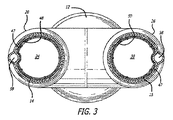
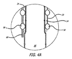
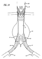
図1〜6は、腹部大動脈瘤の治療のためのモジュール式グラフトアセンブリ10の分岐実施形態を示す。グラフトアセンブリ10は、分岐主要グラフト部材12と、同側グラフト延長部14と、対側グラフト延長部15とを含む。主要グラフト12は、その中に配置される主要流動管腔18に結合する壁部分16を有する。主要グラフト12の同側脚20は、同側ポート22と、主要流動管腔18および同側ポート22と流体連通している同側流動管腔24とを有する。主要グラフト12の対側脚26は、対側ポート28と、主要流動管腔18および対側ポート28と流体連通している対側流動管腔30と、を有する。主要グラフト12、同側脚20、および対側脚26は、分岐した「Y」形構成を形成する。
1-6 show a bifurcated embodiment of a
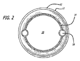
主要グラフト12の主要流動管腔18(図2に示される)は、概して、それぞれ同側脚20または対側脚26の流動管腔24および30(図3に示される)のいずれの横断寸法および面積よりも大きい横断寸法および面積を有してもよい。近位アンカー部材32は、主要グラフト12の近位端31に配置される。近位アンカー部材32は、いずれの末端にも4つのクラウンまたは頂点を有する略蛇行形状を有する細長い要素から形成される近位自己拡張型ステント32Aを含む。近位ステント32Aの各近位頂点またはクラウンは、8クラウンの遠位自己拡張型ステント32Bの交互の遠位クラウンまたは頂点に連結される。遠位自己拡張型ステントは、略蛇行形状を有する細長い要素から形成される。遠位ステント32Bの遠位端は、主要グラフト12の近位端のグラフト材料に埋め込まれるコネクタリングに機械的に連結されるか、または主要グラフトの近位縁領域における穿孔に直接連結されてもよい。コネクタリングの実施形態は、略円形であり、実質的に正弦曲線形であってもよい周囲の周りに規則正しい波形を有してもよい。近位ステント32Aは、近位ステント32Aが拡張状態で配備される管腔の内面の組織を貫通するように構成される鋭い組織穿通先端を有する、いくつかの実施形態のために、ステントの支柱と一体的に形成されてもよい外向きに延長する鉤部33を含む。近位アンカー部材32は、自己拡張型ステント32Aおよび32Bを含むように示されるが、片方または両方のステント32Aおよび32B内からの拡張可能バルーンの拡張によって生成されてもよい外向き半径方向の圧力により非弾性的に拡張されるように構成される同様のステントを使用してもよい。近位ステント32Bに連結されるコネクタリングは、非弾性的に拡張可能であってもよい。
The main flow lumen 18 (shown in FIG. 2) of the
グラフトアセンブリ10およびその構成要素、ならびにグラフト延長部14および15等の本明細書において記述されるグラフト実施形態について、「近位」という用語は、患者の心臓へ向かう位置を指し、「遠位」という用語は、患者の心臓から離れる位置を指す。本明細書において記述される送達システムカテーテルおよびその構成要素について、「遠位」という用語は、カテーテルを使用しているオペレータから離れるように配置される位置を指し、「近位」という用語は、オペレータへ向かう位置を指す。
For the graft embodiments described herein, such as
同側グラフト延長部14は、その中に配置される流動管腔44を有する。同側グラフト延長部14は、主要グラフト12の同側脚の内面へ密封される大きさであり、そのように構成されてもよい外面を有し、同側脚20の流動管腔24と流体連通している同側グラフト延長部14の内側流動管腔44を有する。典型的には、グラフト延長部14の外面46は、グラフト延長部14が配備状態である場合、主要グラフト12の同側脚20の内面48へ密封されてもよい。対側グラフト延長部15は、その中に配置される流動管腔45を有する。対側グラフト延長部15は、主要グラフトの対側脚26の内面へ密封される大きさであり、そのように構成されてもよい外面を有し、対側脚26の流動管腔30と流体連通している内側流動管腔45を有する。典型的には、グラフト延長部15の外面47は、グラフト延長部15が配備状態である時に、主要グラフト12の対側脚26の内面50へ密封されてもよい。いくつかの実施形態のために、同側および対側脚20および26の軸方向長さは、グラフト延長部14および15を適所に保持するために十分な摩擦を提供するためのグラフト延長部14および15の外面46および47と、脚20および26のそれぞれの内面48および50との間の適度な表面積の接触を提供するために十分であってもよい。脚と延長部との間の重複の量を変化させることは、異なる効果的グラフト全長が得られることを可能にするため、そうでなけれは必要とされる寸法より少ない異なる本体および延長部寸法を有する解剖学的寸法の範囲に対応する。いくつかの実施形態のために、同側および対側脚20および26は、少なくとも約1cmの軸方向長さを有してもよい。いくつかの実施形態のために、同側および対側脚20および26は、約2cm〜約6cm、より具体的には、約3cm〜約5cmの軸方向長さを有してもよい。
The
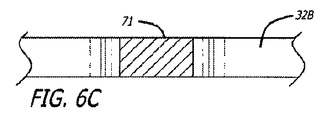
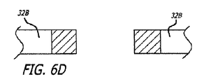
グラフト延長部14および15は、PTFEまたはePTFE等の可撓性グラフト材料の内層および外層から形成されてもよい。グラフト材料の内側および外層は、管状押し出し型材、グラフト材料等の多層膜の積層ラップから形成されてもよい。いくつかの実施形態のために、グラフト材料の内側または外層は、透過性、半透過性、または実質的に非透過性であってもよい。いくつかの実施形態のために、延長部14および15の表面の長さは、透過性であり、半透過性または非透過性である中央の長手方向の部分等の1つ以上の長手方向の部分を有してもよい。グラフト延長部14および15のいくつかの実施形態は、グラフト延長部が弛緩拡張状態である場合、先細になるか、または広がる表面の内側管腔を伴う、概して先細または張出の構成を有してもよい。材料の積層ラップを含む実施形態のために、ラップは、円周方向に、螺旋状に、または任意の他の好適な構成で行われてもよい。
The
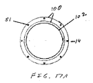
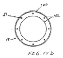
半径方向に拡張可能なステント51は、延長部14および15のグラフト材料の外層54と内層56との間に介在してもよい。グラフト材料の外層と内層との間に配置される介在ステントは、複数の長手方向に間隔を置いて配置された巻きにより螺旋状に巻かれる細長い弾性要素から開いた管状構成へと形成されてもよい。螺旋巻きステント51は、自己拡張型ステント、または拡張可能バルーン等のデバイスからの外向き半径方向の力によって作動される非弾性的方法によって半径方向に拡張可能であるように構成されてもよい。グラフト延長部14および15のために使用してもよい、いくつかの管状プロテーゼの実施形態は、参照することによって、その全体として本明細書に組み込まれる、Goldsらの2000年5月16日出願の米国特許第6,673,103号(名称「Mesh and Stent for Increased Flexibility」)に記述される。
A radially
グラフト延長部14および15は、それらのそれぞれの近位端の外面46および47(図3に示される)上に配置される取付要素、または主要グラフト12のそれぞれの同側脚20および対側脚の内面上に配置される対応する取付要素に連結するために使用してもよい部分を随意に含んでもよい。グラフト延長部14および15の外面46および47、ならびに主要グラフト12の脚20および26の内面48および50上で使用してもよい取付要素の実施形態は、参照することによって、その全体として本明細書に組み込まれる、2005年9月22日出版、Stephensらの2005年3月11日出願の国際特許出願第PCT/US2005/008119号「モジュール式血管内グラフト」における任意の取付要素を含んでもよい。取付要素を有するシステム10等のモジュール式グラフトのいくつかの実施形態は、グラフト本体12等の第1のグラフト胴部管、延長部14および15等の第2のグラフト胴部管を含んでもよい。第1のグラフト胴部管は、第1の壁部分と、第1の壁部分上に配置される第1の取付要素とを有してもよく、第2のグラフト胴部管は、第2のグラフト胴部管の第2の壁部分上に配置される第2の取付要素を有してもよい。第2の取付要素は、第1および第2のグラフト胴部管のそれぞれの流動管腔が、合わせて密封される状態で第1の取付要素に固定されるように構成されてもよい。いくつかの実施形態のために、第1および第2の取付要素は、第1および第2のグラフト胴部管の重複部分において合わせて固定されてもよい。いくつかの実施形態のために、第1の取付要素は、複数の可撓性フックを含んでもよく、第2の取付要素は、互いに隣接する複数の可撓性ループを含み、可撓性フックは、第1および第2の取付要素が合わせて押し付けられる時に、可撓性ループに機械的に係合するように構成される。いくつかの実施形態のために、第1の取付要素は、第1の壁部分の表面上で互いに規則的に間隔を置いて配置される拡大ヘッド部分を有する複数のボタンを含み、第2の取付要素は、メッシュが円周方向に拘束された状態である間、ボタンの拡大ヘッド部分の侵入を可能にし、メッシュが円周方向に拡張された状態である間、ボタンの拡大ヘッド部分を捉えるように構成される複数の開口を有する拡張可能メッシュを含む。いくつかの実施形態のために、第1の取付要素は、第1の壁部分の表面から半径方向に延長する複数のピンを含み、第2の取付要素は、第1の取付要素が第2の取付要素に対して押し付けられる時に、ピンの侵入を可能にするように構成される複数の開口を有する拡張可能メッシュを含む。いくつかの実施形態のために、第1の取付要素は、硬化型材料を含有する膨張式カフを含んでもよく、第2の取付要素は、膨張式カフおよび硬化型材料へ外向きに延長するように構成される鉤部を有する拡張可能部材を含む。
The
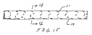
半径方向に拡張状態にあるいくつかの主要グラフト実施形態12の主要流動管腔18の横断寸法および横径は、約12.0mm〜約32.0mmであってもよい。いくつかの実施形態のために、それぞれの同側脚20および対側脚26の同側および対側流動管腔24および30横断寸法および横径は、約5mm〜約20mmであってもよい。対側脚26の軸方向長さは、図1において矢印57によって示される。いくつかの実施形態のために、脚20および26の長さは、約2cm〜約6cmであってもよい。半径方向に拡張である時にグラフト延長部14および15のいくつかの実施形態の横断寸法は、約5mm〜約26mmであってもよい。グラフト延長部14および15のいくつかの実施形態の軸方向長さは、約2cm〜約15cm、具体的には、約5cm〜約10cmであってもよい。同側および対側延長部グラフト14および15のいくつかの実施形態は、拡張状態における場合、約10mm〜約30mm、より具体的には、約15mm〜25mmの外側横断寸法または横径を有してもよい。
The transverse dimension and transverse diameter of the main flow lumen 18 of some
主要グラフト12ならびに同側グラフト延長部14および15は、拡張ポリテトラフルオロエチレン(ePTFE)を含んでもよいポリテトラフルオロエチレン(PTFE)から少なくとも部分的に作製されてもよい。特に、主要グラフト12ならびにグラフト延長部14および15は、高強度のステント、コネクタリング等の支持または補助的構造がない、柔軟なグラフト材料単独に対して約0.003インチ〜約0.015インチの非圧縮層状厚さを有する、約2〜約15の層を含む、任意の数のPTFEおよび/またはePTFEの層を含んでもよい。具体的に明記しない限り、本明細書において使用される「PTFE」という用語は、PTFE、多孔性PTFE、およびePTFEを含み、いずれも、不浸透性、半透過性、または透過性であってもよい。さらに、本明細書において記載される本体および延長部を含むグラフトアセンブリおよびその任意の部位は、すべてのPTFE、すべてのePTFE、またはその組み合わせを含んでもよい。そのようなグラフト胴部管は、グラフト用途に好適な、DACRON等の任意の代替の高強度の柔軟な生体適合性材料も含んでもよい。本明細書において記述される任意の実施形態のために任意の好適な組み合わせにおいて使用してもよいグラフト胴部管の種々の構成およびグラフトアセンブリ10の他の構成要素の説明は、Chobotovらによる2001年12月20日出願の米国特許出願第10/029,557号、公開第US2003/0116260A1号(名称「Method and Apparatus for Manufacturing an Endovascular Graft Section」)、Chobotovらによる2001年12月20日出願の米国特許出願第10/029,584号(名称「Endovascular Graft Joint and Method of Manufacture」)、Chobotovらによる2001年12月20日出願の米国特許出願第10/029,559号(名称「Method and Apparatus for Shape Forming Endovascular Graft Material」)、Chobotovらによる2002年12月20日出願の米国特許第7,147,660号(名称「Advanced Endovascular Graft」)、Humphreyらによる2005年4月13日出願の米国特許出願第11/106,131号、公開第US2006/0233990A1号(名称「PTFE Layers and Methods of Manufacturing」)、およびHumphreyらによる2005年4月13日出願の米国特許出願第11/106,150号、公開第US2006/0233991号(名称「PTFE Layers and Methods of Manufacturing」)で見ることができ、これらのそれぞれの全体は参照することによって本明細書に組み込まれる。
The
同側および対側脚20および26、延長部14および15、またはこれらのすべてを含む、グラフト部材12の種々の部分の積層構造は、種々の構成を含んでもよく、同様であるが異なる特性を有する積層材料は、合わせて、または個々に使用してもよい。例えば、グラフト部材12の本体部分のいくつかの実施形態は、約5ミクロン〜約35ミクロン、より具体的には、約10ミクロン〜約25ミクロンの平均結節間隔、および約0.0002インチ〜約0.002インチ、より具体的には、約0.0005インチ〜約0.0015インチの厚さを有する多孔性ePTFE材料の約1つの層〜約5つの層の積層構造を有してもよい。グラフト部材12の本体部分は、第1の透過性、および約0.0002インチ〜約0.002インチ、より具体的には、約0.0004インチ〜約0.001インチの厚さを有する半透過性のPTFEの約1つの層〜約5つの層も含んでもよい。本体部分は、第1の透過性と異なる第2の透過性、および約0.0002インチ〜約0.002インチ、より具体的には、約0.0004インチ〜約0.001インチの厚さを有する半透過性のPTFE材料の約1つの層〜約5つの層も含んでもよい。上記で参照することによって組み込まれる、米国特許出願第2006/0233990号および同第2006/0233991号において記述されるPTFEの半透過性層の任意の好適な実施形態は、これらの実施形態において使用してもよい。本体部分は、本質的に結節間隔を有さず、非常に低い液体透過性か、または液体透過性を有さず、約0.0001インチ〜約0.0015インチ、より具体的には、約0.0002インチ〜約0.001インチの厚さを有するPTFEの約1つの層〜約5つの層も含んでもよい。
The laminated structure of the various parts of the
取付要素を含まないモジュール式グラフトシステムの実施形態のために、グラフト延長部14および15の近位端の外面46および47は、グラフト部材12の脚20および26の流動管腔の内面48および50のそれぞれに対して拡張されてもよい。この構成は、グラフト延長部14および15の流動管腔44および45を、脚20および26の流動管腔24および30へ密封するために使用してもよい。拡張可能固定部材等の拡張可能部材は、グラフト延長部14および15を、脚20および26の流動管腔24および30の内面48および50に対して拡張させるために使用してもよい。
For embodiments of modular graft systems that do not include attachment elements, the outer surfaces 46 and 47 of the proximal ends of the
膨張式要素またはチャネル58の網状組織は、主要グラフト12上に配置され、膨張式チャネル58の網状組織と流体連通している、その中に配置される管腔を有する主要充填ポート60を通って膨張材料(図示せず)による圧力下で膨張させられてもよい。膨張材料は、主要充填ポート60の管腔内に配置される一方向弁(図示せず)によって膨張式チャネル58の網状組織内に保持されてもよい。膨張式チャネル58の網状組織は、固まるか、硬化するか、そうでなければチャネルへ注入された後に粘度を増すか、またはより剛性になるように構成されてもよい硬化性材料で随意に充填されてもよい。ゲル、液体、またはより固体、もしくは実質的に硬化状態まで硬化可能である他のフロー可能な材料等の硬化性膨張材料は、チャネル内に配置される硬化した材料の機械的特性に基づいて機械的支持を主要グラフト12および脚に提供するために使用してもよい。増加した内圧を維持することができる限り、生理食塩水等の非硬化性膨張材料が使用されても、膨張式チャネル58の網状組織は、増加した内圧によって生成されるチャネルの硬直性のために膨張状態である時に、構造的支持を主要グラフト12にも提供してもよい。硬直性または剛性におけるそのような増加は、種々の目的に有用であってもよい。例えば、配備の間、膨張式チャネルの網状組織の膨張は、主要フローチャネルおよびその脚を含む主要グラフト本体を、開いた流動管腔を有する略円筒形構成に一致させることを促してもよく、それは、送達カテーテル、ガイドワイヤ等によって対側または同側脚の流動管腔を配置し、誘導しようとする時に有用であってもよい。主要グラフト本体の流動管腔およびその部分のそのような位置および誘導は、蛍光画像化の下での視覚化の強化を提供する放射線不透過性膨張材料の使用によっても容易にされてもよい。
The network of inflatable elements or
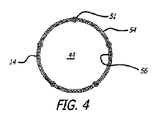
膨張式チャネル58の網状組織は、主要グラフトまたは主要グラフトの脚の周りに完全または部分的に配置される1つ以上の周囲チャネル、および支持を提供してもよい縦または螺旋チャネル、ならびに膨張式チャネルの網状組織を膨張材料で充填するために使用してもよい周囲チャネルと連通している導管を含んでもよい。いくつかの実施形態は、充填プロセス、および続くグラフト延長部の係合のモニタリングを容易にするために放射線不透過性膨張材料も使用してもよい。膨張式チャネル58の網状組織は、患者の腹部大動脈等の患者の血管の内面へ密封するように構成されてもよい、近位膨張式カフ62等の膨張式カフの形の1つ以上の拡大周囲チャネルも含んでもよい。近位膨張式カフ62は、近位アンカー部材32の主要グラフト12遠位の近位部分上に配置され、主要グラフト12の表面の外面から半径方向に延長する外面を有する。膨張式カフ62は、主要グラフト12の表面の外面を越えて半径方向に拡張するように構成されてもよく、膨張式カフ62が拡張状態まで膨張材料によって膨張される時に、体腔の内面に対する密封を提供する。近位アンカー部材32および近位膨張式カフ62の軸方向の分離は、主要な固定機構および密封機能の少なくとも一部の空間的分離を可能にし、それは、グラフトが拘束されるか、またはそうでなければ送達カテーテルからの配備のためのより小さい外側プロファイルに圧縮されることを可能にしてもよい。膨張式カフ62の内部空洞は、膨張式チャネルの残りの網状組織の内部空洞と流体連通し、約0.040インチ〜約0.250インチの横断寸法または内径を有してもよい。
The network of
主要グラフト部材12のいくつかの実施形態は、各脚20および26の周りに配置される約1〜約8つの周囲膨張式チャネルと、主要グラフト部材12の本体部分の周りに配置される約1〜約8つの周囲チャネルとを含んでもよい。主要グラフト本体部材12のいくつかの実施形態は、周囲膨張式チャネルを接続するよう機能してもよい約1〜約4つの長手方向または軸方向膨張式チャネルを含んでもよい。周囲チャネルのいくつかの実施形態は、それらが配置されるグラフト部分の完全円周方向に延長してもよいか、またはそれらは、それらが配置されるグラフト部分の周りに部分的にのみ延長してもよい。図1に示される主要グラフト部材実施形態12のために、膨張式チャネル58の網状組織は、主要グラフト部材12の本体部分の近位端に隣接して配置される膨張式カフ62と、膨張式カフ62のちょうど遠位に配置される周囲チャネルとを含む。主要グラフト部材12の各脚20および26は、軸方向の直列に3つの完全周囲膨張式チャネルを含む。各脚20および26は、完全周囲膨張式チャネルの近位に配置される2つの部分的周囲膨張式チャネルも有する。長手方向または軸方向チャネルは、同側脚20の充填ポート60および周囲チャネル、ならびに本体部分の近位端にある周囲チャネルおよび膨張式カフ62と流体連通している主要グラフト部材12の同側に実質的に沿って延長する。別の軸方向チャネルは、カフ62、本体部分の近位端にある周囲チャネル、および対側脚26の周囲チャネルと流体連通している主要グラフト部材12の対側の全体に沿って延長する。
Some embodiments of the
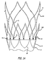
本明細書において記述されるグラフト部材実施形態の膨張式チャネルのいくつかは、図1に示される等、円周方向および軸方向に配置されてもよい。代替として、そのような膨張式チャネルは、渦巻き状、螺旋状、または他の構成で配置されてもよい。本発明の実施形態に好適なチャネル構成の例は、Kariらの2003年3月6日出願の米国特許出願第10/384,103号(名称「Kink Resistant Endovascular Graft」)においてさらに記載され、この全体は、参照することによって本明細書に組み込まれる。円周方向のものとして本明細書に記載されるすべての膨張式チャネル実施形態は、代替として、前述の代替構成のいずれをも採用してもよい。他のモジュール式グラフト実施形態は、Chobotovらの2005年4月1日出願の出願中である米国特許出願第11/097,718号、2006/0224232号(名称「Hybrid Modular Endovascular Graft」)に記述され、この内容は、参照することによって、その全体として本明細書に組み込まれる。 Some of the inflatable channels of the graft member embodiments described herein may be circumferentially and axially disposed, such as shown in FIG. Alternatively, such inflatable channels may be arranged in a spiral, spiral, or other configuration. Examples of channel configurations suitable for embodiments of the present invention are further described in US patent application Ser. No. 10 / 384,103 (named “Kink Resistant Endovascular Graph”) filed March 6, 2003, to Kari et al. The entirety is hereby incorporated by reference. All inflatable channel embodiments described herein as being circumferential may alternatively employ any of the previously described alternative configurations. Other modular graft embodiments are described in US patent application Ser. Nos. 11 / 097,718, 2006/0224232 (named “Hybrid Modular Endovascular Graph”) filed April 1, 2005 to Chobotov et al. The contents of which are hereby incorporated by reference in their entirety.
膨張式カフ62および膨張式チャネル58の他の網状組織は、任意の好適な膨張材料により、グラフトの配備の間に充填されてもよい。上述のように、膨張材料は、膨張式カフ62または膨張式チャネル58の網状組織の内側から外向きの圧力または剛性構造を提供するために使用してもよい。Hubbellらの2000年2月1日出願の出願中である米国特許出願第09/496,231号(名称「Biomaterials Formed by Nucleophilic Addition Reaction to Conjugated Unsaturated Groups」)、Hubbellらの2000年6月2日出願の出願中である米国特許出願第09/586,937号(名称「Conjugate Addition Reactions for Controlled Delivery of Pharmaceutically Active Compounds」)に記載され、Chobotovらの2002年12月20日出願の共同所有の出願中である米国特許出願第10/327,711号(名称「Advanced Endovascular Graft」)にさらに記述される、ポリマー生体材料等の硬化型ポリマー材料またはゲルを含む、生体適合性ガス、液体、ゲル等を使用してもよく、これらのそれぞれは、参照することによって、その全体として本明細書に組み込まれる。いくつかの実施形態は、AskariおよびWhirleyらの2005年4月1日出願の米国特許出願第11/097,467号、公開第2006/0222596号(名称「Non−Degradable,Low−Swelling,Water Soluble Radiopaque Hydrogel Polymer」)に記述される、グリシジルエーテルおよびアミン材料から形成される膨張材料を使用してもよい。いくつかの膨張材料実施形態は、第1の量のジアミンおよび第2の量のポリグリシジルエーテルを有するそのままの状態で形成されるヒドロゲルポリマーを含んでもよく、量のそれぞれは、生体適合性であり、約10秒〜約30分の混合後に硬化時間を有するそのままの状態で形成されるヒドロゲルポリマーを産生するための量で哺乳類、または哺乳類に配置される、膨張式グラフト等の医用デバイスの中に存在し、ヒドロゲルポリマーの体積は、硬化および脱水後に30パーセント未満膨張する。膨張材料のいくつかの実施形態は、ヨウ化ナトリウム、ヨウ化カリウム、硫酸バリウム、ビジパーク320、ヒパーク、オムニパーク350、ヘキサブリックス等の放射線不透過性材料を含んでもよい。いくつかの膨張材料実施形態ために、ポリグリシジルエーテルは、トリメチロールプロパントリグリシジルエーテル、ソルビトールポリグリシジルエーテル、ポリグリセロールポリグリシジルエーテル、ペンタエリトリトールポリグリシジルエーテル、ジグリセロールポリグリシジルエーテル、グリセロールポリグリシジルエーテル、トリメチロールプロパンポリグリシジルエーテル、ポリエチレングリコールジグリシジルエーテル、レゾルシノールジグリシジルエーテル、p−ヒドロキシル安息香酸のグリシジルエステルエーテル、ネオペンチルグリコールジグリシジルエーテル、1,6−ヘキサンジオールジグリシジルエーテル、ビスフェノールA(PO)2ジグリシジルエーテル、ハイドロキノジグリシジルエーテル、ビスフェノールSジグリシジルエーテル、テレフタル酸ジグリシジルエステル、およびそれらの混合物より選択されてもよい。いくつかの膨張材料実施形態ために、ジアミンは、ポリエチレングリコール(400)ジアミン、ジ−(3−アミノプロピル)ジエチレングリコールr、ポリオキシプロピレンジアミン、ポリエーテルジアミン、ポリオキシエチレンジアミン、トリエチレングリコールジアミン、およびそれらの混合物から成る群より選択されるアミノまたはアルキルアミノ末端を有する(ポリ)アルキレングリコールより選択される。いくつかの実施形態のために、ジアミンは、親水性であってもよく、ポリグリシジルエーテルは、硬化前に親水性であってもよい。いくつかの実施形態のために、ジアミンは、親水性であってもよく、ポリグリシジルエーテルは、硬化前に親水性である。いくつかの実施形態のために、ジアミンは、疎水性であってよもく、ポリグリシジルエーテルは、硬化前に親水性であってもよい。
The
いくつかの実施形態のために使用してもよい他の膨張材料は、参照することによって、その全体として本明細書に組み込まれる、米国特許第6,610,035号および同第6,176,849号に記述される、ポリエチレンオキシド材料およびネオペンチルグリコールジアクリレート材料を含む。上述される米国特許第7,147,660号は、本明細書において記述される実施形態のために使用してもよい膨張材料実施形態も含む。 Other inflatable materials that may be used for some embodiments are described in US Pat. Nos. 6,610,035 and 6,176, which are hereby incorporated by reference in their entirety. Polyethylene oxide materials and neopentyl glycol diacrylate materials described in US Pat. No. 849. US Pat. No. 7,147,660 mentioned above also includes inflatable material embodiments that may be used for the embodiments described herein.
図1Aを参照すると、近位アンカー部材32は、主要グラフト12の近位端上に配置され、主要グラフト12の近位部分上に少なくとも部分的に配置されるコネクタリング68に固定されてもよい。いくつかの実施形態のために、コネクタリング68は、主要グラフト12の近位区分のグラフト材料に埋め込まれてもよく、また、コネクタリング68に隣接するPTFE層の1つ以上のフラップ要素によって固定されてもよい。隣接する層のフラップは、コネクタリングを覆うように畳まれ、コネクタリング68、PTFE材料の隣接する層、または両方に固定されてもよい。FEP等の接着材料も、コネクタリング68を主要グラフト本体12に固定させるために使用されてもよい。近位コネクタリング68は、主要グラフト12のグラフト材料の近位端を越えてコネクタリング68から近位に延長するコネクタ要素70を有する。コネクタ要素は、近位アンカー部材32の遠位ステント32Bの遠位側から遠位に延長する、近位アンカー部材32の接合コネクタ要素に連結するか、またはそうでなければそれに固定されるために使用してもよい。近位アンカー部材32は、概して、円筒の蛇行または正弦波パターンで成型されている固定部材の近位および遠位ステント32Aおよび32Bの細長い要素を伴う、円筒形またはリング様構成を有してもよい。近位アンカー部材は、種々の体腔構成の中で固着することを可能にする横断寸法および横径を有してもよい。患者の腹部大動脈における使用のために好適であってもよい近位アンカー部材32のいくつかの実施形態は、約20mm〜約40mmの横断寸法および横径を有してもよい。近位アンカー部材32を形成する細長い要素は、約0.005インチ〜約0.040インチの半径方向の厚さを有してもよい。近位アンカー部材32を形成する細長い要素の幅は、約0.01インチ〜約0.2インチであってもよい。上述される米国特許第7,147,660は、本明細書において記述される実施形態のために使用してもよい固定部材実施形態も含む。
With reference to FIG. 1A, the
近位アンカー部材32は、図5Aおよび5Bに示されるように、フランジコネクタ要素70を伴うコネクタリング68に固定される。フランジコネクタ要素70は、コネクタ要素70の中間部分より大きい横断寸法を有するコネクタ要素70のフランジ部分の耳の間に嵌るように構成されるワイヤコイル70Aと合わせて固定されてもよい。フランジ部分は、コイル70Aが2つの隣接するコネクタ要素70に対して載り、かつそれを合わせて機械的に捕らえるようにコイル70Aに対する一対の対向表面を提供する。フランジ要素を連結するために使用されるワイヤコイル70Aは、約0.005インチ〜約0.050インチ、より具体的には、約0.010インチ〜約0.030インチの内側横断寸法を有し、かつそれらの直径の約2〜約15倍、より具体的には、それらの直径の約4〜約8倍の軸方向長さを有する。
The
再度、図1Aを参照すると、近位ステント32Aは、図6A〜6Dにより詳細に示される、2つのステントの隣接するクラウンの間に配置される支柱71によって近位アンカー部材32の遠位ステント32Bに連結される。支柱は、ステント32Aおよび32Bならびに支柱の材料の断面積が遠位ステントの近位部分から近位ステントの遠位部分で実質的に一定のままであるように構成されてもよい。いくつかの実施形態のために、支柱71の部分における材料の断面積は、支柱71に隣接する近位ステント32Bまたは遠位ステント32Aのいずれかの断面積より大きい。そのような構成は、近位と遠位ステント32Aおよび32Bとの間の接合部での応力および歪み集中を回避する際に有用であってもよい。
Referring again to FIG. 1A, the
同様の構造的構成は、コネクタリング68と遠位ステント32Bの遠位端との間の接合部で使用してもよい。この接合部のために、図5Aに示されるように、コネクタリング68とコネクタ要素70との間に配置される支柱72は、コネクタ要素70に隣接するコネクタリング68の断面積と実質的に同一か、またはそれより大きい断面積を有してもよい。加えて、遠位ステント32Bの遠位端と遠位ステント32Bのコネクタ要素70との間に配置される支柱73は、支柱73に隣接する遠位ステント32Bの断面積と実質的に同一か、またはそれより大きい断面積を有してもよい。この構成は、コネクタリング68と近位アンカー部材32の遠位ステント32Bとの間の接合部における応力および歪み集中を回避する際に有用であってもよい。
A similar structural configuration may be used at the junction between the
近位アンカー部材32およびその構成要素は、経皮的または他の種類の送達のための小さい横断寸法および直径へと折り畳め、かつ患者の血管系の内面に係合して血管系への固着を提供し、固定部材またはそれに取り付けられるグラフト部分の軸方向の動きを防止または対抗するように拡張可能であってもよい種々の構成を有してもよい。固定部材の実施形態32は、波形を有する自己拡張型固定部材として構成されてもよく、ステンレス鋼、ニッケルチタン合金、または任意の他の好適な材料から作製されてもよい。固定部材32は、半径方向に圧縮された状態から外向き半径方向にバルーン拡張可能または自己拡張型であるように構成されてもよい。遠位固定部材32およびコネクタリング68は、上述される材料等の選択された材料の単一環状部品からこれらの要素の構成を切断することによって形成されてもよい。固定部材32の近位ステント32Aは、固定部材から外向きに角を成し、配備されてから、血管壁の組織に係合し、固定部材の軸方向の動きを防止するように構成される鉤部33を随意に含んでもよい。近位アンカー部材32およびその近位および遠位ステント32Aおよび32Bは、参照することによってその全体において組み込まれる、Chobotovらの2002年12月20日出願の第10/327,711号、US2003/0125797A1号に記載されるステントと同一または同様の特徴、寸法、または材料を有してもよい。固定部材32の遠位ステント32Bは、上記の組み込まれた出願に記載される同一または同様の方法でコネクタリング68に固定されてもよい。
The
主要グラフト12のいくつかの実施形態のために、1つ以上のグラフト延長部14および15による補足により幅広い血管形態における主要グラフト12の使用を可能にするように構成される呼び軸方向長さを有することは有用であってもよい。モジュール式グラフト実施形態10は、通常、患者の血管系への適切な嵌合を有するために選択される。いくつかのグラフト適用のために、各患者の血管系の寸法および構成変化に対応し、患者の血管系内のグラフトアセンブリ10の許容可能な適合を得るために、グラフトシステムの多数の寸法変化、またはグラフトアセンブリ10構成要素を作製する必要がある。これは、血管内グラフトアセンブリ10の製造評者、およびデバイスの総合的在庫を維持しなければならない病院にとって、非常に高価であり、多大な時間を必要とする。加えて、これは、病院の手術室またはカテーテル検査室における棚スペースの不便な量を必要とする場合がある。いくつかの実施形態のために、主要グラフト部材12は、幅広い階層の多様な体格および血管構成を有する患者において、分岐した部分の脚が腸骨動脈を避けた状態で、患者の大動脈から延長する腎動脈に隣接する近位アンカー部材32の固着を可能にするように選択される軸方向長さを有してもよい。このようにして、特定の患者または患者群のためにグラフトアセンブリ10をカスタマイズする必要を回避することができる。
For some embodiments of the
いくつかの実施形態のために、主要グラフト部材12の軸方向長さ、特に近位アンカー部材32と、同側および対側脚20および26の遠位端との間の軸方向の距離または分離は、選択された患者の腸骨動脈へ延長せずに腹部大動脈瘤にわたって延長するように選択されてもよい。選択された患者は、腎動脈のちょうど遠位にある大動脈における密封点と、腸骨動脈にある最遠位実行可能アンカーおよび密封点との間の最長軸方向の分離を有する患者群のメンバーであってもよい。特定の患者群に対するいくつかの実施形態では、主要グラフト部材12の近位端は、図1における矢印74によって示されるように、約5cm〜約10cm、より具体的には、約6cm〜約8cmの長さで同側および対側脚20および26の遠位端から軸方向に分離される。
For some embodiments, the axial length or separation of the axial length of the
主要グラフト部材実施形態12の寸法を決定するいくつかの実施形態のために、近位アンカー部材32および配備されたグラフト延長部14および15の遠位端の分離は、分離が、腎動脈と、患者の腸骨動脈または動脈における最近位アンカーおよび密封点との間の分離に架かるためにちょうど十分に長くなるように選択される。この距離は、患者の選択された群において、患者の選択された群における最長のそのような分離を有する患者から決定されてもよい。加えて、これらの実施形態のために、この分離は、腎動脈と内腸骨動脈との間の分離より短くなければならない。距離は、患者の選択された群において、患者の選択された群における最短のそのような分離を有する患者から決定されてもよい。このようにして、共通の主要グラフト本体長さを有する主要グラフト部材12実施形態により患者の選択された群のすべてのメンバーを治療することが可能であり得る。そのような実施形態は、腎動脈または内腸骨動脈のいずれも遮断せずに患者の腎動脈の遠位にある患者の大動脈に固着され、患者の腸骨動脈の中に遠位に固着されてもよい。そのようなモジュール式グラフトシステム実施形態10は、主要グラフト部材12および約10cm〜約22cm、具体的には、約11cm〜約20cmの配備されたグラフト延長部14および15を含む全長を有してもよい。
For some embodiments of determining the dimensions of the main
主要グラフト12の慎重な寸法設定および構成は、単一主要グラフト12実施形態または設計の使用が、1つ以上のグラフト延長部14および15によって補足される時に、幅広い患者に適応可能となることを可能にする。より具体的には、約5cm〜約8cmの軸方向長さを有する主要グラフト12は、潜在患者の高い割合において適切に配備され得る。配備されると、主要グラフト12の同側および対側脚20および26の流動管腔24および30は、グラフト延長部14および15の配備により患者の腸骨動脈へ密封することができる。グラフトアセンブリ10は、グラフト延長部14および15を主要グラフト12の同側脚および対側脚に固定するために取付要素を使用する選択肢を含むが、これは、ほとんどの場合必要ない可能性があり、グラフト延長部14および15の適度な密封および機械的固定は、取付要素の代わりに、グラフト延長部14および15上での標準的拡張可能部材の使用により得ることができる。
Careful sizing and configuration of the
患者を治療する方法のいくつかの実施形態は、半径方向に拘束された分岐主要グラフト部材を含有する送達カテーテルを提供するステップを含む。主要グラフト部材は、その中に主要流動管腔を有し、主要流動管腔と連通している同側流動管腔を伴う同側脚、および主要流動管腔と連通している対側流動管腔を伴う対側脚を有する柔軟なグラフト材料から形成されてもよい。主要グラフト部材は、主要グラフト部材上に配置される膨張式チャネルの網状組織も含んでもよい。膨張式チャネルの網状組織は、主要グラフト部材を含む同側および対側脚を含む主要グラフト部材の任意の部位上に配置されてもよい。主要グラフト部材は、主要グラフト部材の近位端に配置され、かつ主要グラフト部材に固定される近位アンカー部材も含んでもよい。近位アンカー部材は、自己拡張型遠位ステント部分に固定される自己拡張型近位ステント部分を有してもよい。 Some embodiments of a method for treating a patient include providing a delivery catheter containing a radially constrained branch main graft member. The main graft member has a main flow lumen therein, an ipsilateral leg with an ipsilateral flow lumen in communication with the main flow lumen, and a contralateral flow tube in communication with the main flow lumen. It may be formed from a flexible graft material having a contralateral leg with a cavity. The main graft member may also include a network of inflatable channels disposed on the main graft member. The network of inflatable channels may be disposed on any portion of the main graft member including the ipsilateral and contralateral legs including the main graft member. The main graft member may also include a proximal anchor member disposed at the proximal end of the main graft member and secured to the main graft member. The proximal anchor member may have a self-expanding proximal stent portion that is secured to the self-expanding distal stent portion.
そのような送達カテーテルは、送達カテーテル内の主要グラフト部材が、患者の大動脈の血管障害と同一の広がりを持って配置されるように、患者の血管系で軸方向に配置されてもよい。この配置が得られると、近位アンカー部材は、患者の血管系の内面に係合し、アンカー部材を患者の大動脈に固着するよう、配備されてもよい。その後、主要グラフト部材の膨張式チャネルの網状組織は、より機械的に剛性な構造を提供するよう、膨張材料で膨張されてもよい。いくつかの実施形態のために、付加的な機械的剛性を提供し、充填材料の漏出を防止するよう、膨張式チャネルの網状組織の膨張後に硬化されてもよい硬化型または硬化性充填材料を使用してもよい。いくつかの実施形態は、充填プロセス、および続くグラフト延長部の係合のモニタリングを容易にするために放射線不透過性膨張材料も使用してもよい。 Such a delivery catheter may be axially positioned in the patient's vasculature such that the main graft member within the delivery catheter is positioned to be coextensive with the vascular lesions of the patient's aorta. Once this arrangement is obtained, the proximal anchor member may be deployed to engage the inner surface of the patient's vasculature and secure the anchor member to the patient's aorta. Thereafter, the network of inflatable channels of the main graft member may be inflated with an intumescent material to provide a more mechanically rigid structure. For some embodiments, a curable or curable filler material that may be cured after expansion of the network of inflatable channels to provide additional mechanical rigidity and prevent leakage of the filler material. May be used. Some embodiments may also use a radiopaque inflatable material to facilitate monitoring of the filling process and subsequent graft extension engagement.
その後、半径方向に拘束された自己拡張型対側グラフト延長部を含有する第2の送達カテーテルは、対側グラフト延長部の近位部分が、主要グラフト部材の対側脚の内側流動管腔と軸方向に重複し、対側グラフト延長部の遠位部分が、患者の対側腸骨動脈の一部と軸方向に重複している状態で主要グラフト部材の対側脚の中で軸方向に配置されてもよい。主要グラフト部分の対側脚へのアクセスは、経皮的アクセス、または送達シース等による患者の対側大腿動脈からの大腿動脈切開によって得られてもよい。適切に配置されると、自己拡張型対側グラフト延長部は、第2の送達カテーテルの半径方向の拘束を解放することによって配備されてもよい。対側グラフト延長部自体が外向き半径方向の配向で拡張する際に、対側グラフト延長部の内側流動管腔と、対側脚の流動管腔と、対側腸骨動脈の流動管腔との間の密封が形成されてもよい。 Thereafter, a second delivery catheter containing a radially constrained self-expanding contralateral graft extension has a proximal portion of the contralateral graft extension and an inner flow lumen of the contralateral leg of the main graft member. Axial overlap and the distal portion of the contralateral graft extension is axially overlapped with a portion of the patient's contralateral iliac artery in the contralateral leg of the main graft member It may be arranged. Access to the contralateral leg of the main graft portion may be obtained by percutaneous access or a femoral artery incision from the patient's contralateral femoral artery, such as by a delivery sheath. When properly positioned, the self-expanding contralateral graft extension may be deployed by releasing the radial restraint of the second delivery catheter. As the contralateral graft extension itself expands in an outward radial orientation, the inner flow lumen of the contralateral graft extension, the flow lumen of the contralateral leg, and the flow lumen of the contralateral iliac artery A seal between the two may be formed.
その後、半径方向に拘束された自己拡張型同側グラフト延長部を含有する第3の送達カテーテルは、同側グラフト延長部の近位部分が、主要グラフト部材の同側脚の内側流動管腔と軸方向に重複し、同側グラフト延長部の遠位部分が、患者の同側腸骨動脈の一部と軸方向に重複している状態で主要グラフト部材の同側脚の中で軸方向に配置されてもよい。その後、自己拡張型同側グラフト延長部は、同側グラフト延長部の内側流動管腔と、同側脚の流動管腔と、同側腸骨動脈の流動管腔との間で密封を形成するよう、半径方向の拘束を解放することによって配備されてもよい。 Thereafter, a third delivery catheter containing a radially constrained self-expanding ipsilateral graft extension has a proximal portion of the ipsilateral graft extension and an inner flow lumen of the ipsilateral leg of the main graft member. Overlapping in the axial direction, with the distal portion of the ipsilateral graft extension axially overlapping a portion of the patient's ipsilateral iliac artery in the ipsilateral leg of the main graft member It may be arranged. The self-expanding ipsilateral graft extension then forms a seal between the inner flow lumen of the ipsilateral graft extension, the flow lumen of the ipsilateral leg, and the flow lumen of the ipsilateral iliac artery. As such, it may be deployed by releasing the radial constraint.
患者の血管系を治療するいくつかの方法実施形態のために、上述されるモジュール式グラフトアセンブリ実施形態10等のモジュール式グラフトアセンブリを使用してもよい。図7〜14は、モジュール式グラフトアセンブリの実施形態の配備順序の実施形態を示す。血管内の方法のために、患者の血管系へのアクセスは、動脈切開または患者の大腿動脈への血管切開を行うことによってか、または経皮的セルジンガー技術等の他の一般的な技術によって得られてもよい。そのような技術のために、送達シース(図示せず)は、拡張器およびガイドワイヤアセンブリの使用により、大腿動脈等の患者の血管の内部と連通して配置されてもよい。送達シースが配置されると、患者の血管系へのアクセスは、止血弁または他の好適な機構によって随意に密封されてもよい送達シースを通って得られてもよい。いくつかの処置のために、患者の大動脈へ上流に向けられる送達シースにより、患者の両方の大腿動脈への送達シースまたは他の好適な手段を解するアクセスを得ることが必要であってもよい。いくつかの用途において、送達シースは、必要ではない場合があり、送達カテーテル75が、動脈切開または経皮的穿刺のいずれかによって患者のアクセス血管へ直接挿入されてもよい。
For some method embodiments for treating a patient's vasculature, a modular graft assembly such as the modular
送達シースが適切に配置されると、グラフト部材12等のモジュール式グラフトアセンブリ構成要素を含有する送達カテーテル75は、送達シースを通って患者の血管系へガイドワイヤ76上を進められてもよい。1つの特定の配備方法実施形態では、主要グラフト部材12は、カテーテルまたは患者の血管系を通る送達の容易性のために低プロファイルおよび横方向可撓性を有する同様のデバイスを介して拘束状態で腹部大動脈等の所望の配備部位へ、典型的には同側腸骨動脈からの近位方向に、患者の血管を通って送達カテーテル75内を進められる。所望の配備部位で、主要グラフト12の近位アンカー部材32は、拘束状態から解放され、近位アンカー部材32は、拡張し、主要グラフト12の一部を患者の血管系に固定することが可能になる。モジュール式グラフトアセンブリ10の配備は、参照することによって、その全体として本明細書に組み込まれる、Chobotovらの2001年7月27日出願の米国特許第6,761,733号(名称「Delivery Systems and Methods for Bifurcated Endovascular Graft」)、およびChobotovらの2005年8月15日出願の米国特許出願第11/205,793号(名称「Delivery System and Method for Bifurcated Graft」)に開示される技術および付随の装置を含む任意の好適なデバイスおよび方法によって実行されてもよい。
When the delivery sheath is properly positioned, a
送達カテーテル75は、図7に示される腸骨動脈78および大動脈79を含む患者の血管系へ、矢印77によって示される血流の上流へ近位に進められてもよい。図に示される患者の血管系の他の血管は、腎動脈80および内腸骨動脈81を含む。送達カテーテル75は、主要グラフト12が大動脈瘤82または治療される他の血管障害に実質的に隣接して配置されるまで、患者の大動脈79へ進められてもよい。送達カテーテル75がそのように配置されると、送達カテーテル75の外側シース83は、図8に示されるように、送達カテーテル75の外側シース83の内側管腔内に適合するように圧縮され、小型化されていた主要グラフト12を露出するように、遠位に引込まれてもよい。送達カテーテル75の外側シース83の内側管腔内に配置されるときに半径方向に圧縮されることに加え、近位ステント32Aおよび遠位ステント32Bは、小プロファイルを維持し、ステント32Aおよび32Bの配備が開始されるまで体腔壁とのステント32Aおよび32Bの係合を回避するために、それぞれの高強度の可撓性ベルト86によって半径方向に抑制されている。ベルト86の端部は、ベルト86の環状端部を通って延長する1つ以上のワイヤまたは細長いロッド88によって固定されてもよい。送達カテーテル75の外側シース83が引込まれると、送達カテーテル75およびグラフトアセンブリ実施形態10は、近位アンカー部材32および近位密封カフ62が動脈瘤82の近位に配置された状態で、遠位ステント32Bが腎動脈80と実質的に同じ高さに配置されるように軸方向に慎重に配置されてもよい。その後、近位アンカー部材32は、配備され、患者の大動脈79に固着される。
近位アンカー部材32の配備は、遠位ステント32Bを抑制するベルト88の端部を連結するワイヤまたはロッド86を引込むことによって遠位ステント32Bの配備から開始してもよい。付加的な軸方向の配置は、典型的には、近位アンカー部材32の遠位ステント32Bを配備した後でも実行されてもよい。これは、遠位アンカー32の遠位ステント部分32Bが、いくつかの実施形態に対して、組織係合鉤部33を含まず、近位ステント32Aが配備されるまで患者の血管79の内側管腔に対する部分的な外向き半径方向の接触または摩擦力のみを提供するために、さらに多くの状況において実行されてもよい。遠位ステント32Bを拘束するベルト86が解放されると、遠位ステント32Bは、近位ステント32Bの外面が図9に示されるの患者の血管79内面90に接触し、かつそれに係合するまで、外向き半径方向に自己拡張する。
Deployment of the
遠位ステント32Bが配備された後に、近位ステント32Aは、近位ステント32Bを抑制するベルト86の端部を連結するワイヤ88を引込むことによって配備されてもよい。近位ステント32Aが外向き半径方向に自己拡張する際に、近位ステント32Aの外面は、最終的に患者の大動脈79の内面90と接触する。近位ステント32A上の組織係合鉤部33を含む実施形態のために、鉤部は、患者の血管79の内面組織90と接触し、かつそれに係合するよう、外向き半径方向に配向され、押されてもよく、それは、図10に示されるように近位アンカー部材32を患者の血管79にさらに固定する。
After the
近位アンカー部材32が患者の血管79の内面90に固定されると、近位膨張式カフ62は、膨張式カフ62の外面を血管79の内面83を密封するように機能することができる送達カテーテル75の膨張管91を通って注入される膨張材料により膨張ポート60を通って充填されてもよい。膨張式チャネル58の残りの網状組織も、図11に示されるように、より剛性なフレーム様構造をグラフト12に提供する、加圧膨張材料により同時に充填されてもよい。いくつかの実施形態のために、膨張材料は、膨張式チャネルの網状組織が網状組織内の材料または圧力の所望のレベルまで充填されると硬化するか、または固まることができる硬化型または硬化性の材料であってもよい。いくつかの実施形態は、充填プロセス、および続くグラフト延長部の係合のモニタリングを容易にするために放射線不透過性の膨張材料も使用してもよい。材料は、時間経過、熱の応用、電磁エネルギーの応用、超音波エネルギーの応用、化学薬品の添加または混合等を含む本明細書において記述される任意の好適な方法によって硬化されてもよい。
When the
膨張式チャネル58の網状組織は、剛性を膨張式チャネル58の網状組織および主要グラフト12に提供するために、主要充填ポート60への好適な膨張材料の注入によって部分的または完全に膨張させられてもよい。加えて、密封は、膨張式カフ62と腹部大動脈82の内面との間で生成される。配備プロセスのこの段階で主要グラフト12の膨張式チャネル58の網状組織を部分的または完全に膨張させることは望ましいが、そのような膨張ステップは、必要に応じて、後の段階で随意に遂行されてもよい。
The network of the
グラフト部材12が固着され、その膨張式チャネル58が充填され、拡張されると、対側グラフト延長部15を含有する第2の送達カテーテル92は、直接または前述のように送達シースを通って対側大腿動脈へアクセスしてもよい。第2の送達カテーテルは、半径方向に圧縮された対側グラフト延長部15が、グラフト部材12の対側脚26に重なる軸方向の位置にくるまで、図12に示されるように、近位に進められてもよい。対側脚26とのグラフト延長部15の所望の重複の量は、血管形態、血管疾患の程度、患者の状態等を含む様々の要因に応じて異なってもよい。しかしながら、いくつかの実施形態のために、対側グラフト延長部15と対側脚26との間の軸方向の重複の量は、約1cm〜約5cm、より具体的には、約2cm〜約4cmであってもよい。この重複位置は、グラフト延長部15の流動管腔45と対側脚26の流動管腔との間の長手方向の重複も提供してもよい。
When the
適切に配置されると、対側グラフト延長部15を半径方向に抑制することができる第2の送達カテーテル92の外側シース94は、グラフト延長部15が実質的に軸方向に固定される間に、遠位に引き抜かれてもよい。第2の送達カテーテル92の外側シース94の軸方向の収縮は、図13に示されるように、グラフト延長部15が半径方向に自己拡張し、対側脚26の内側管腔30および対側脚26の近位にある対側腸骨動脈の内面に係合することを可能にするように、対側グラフト延長部15を配備する。グラフト延長部15は、対側脚26の内側管腔30をグラフト延長部15の内側管腔45に密封させた状態で主要グラフト12の対側脚20を延長するようにそのように配備されてもよい。対側グラフト延長部15が配備されると、第2の送達カテーテル92は、患者の血管系から引き抜かれてもよい。
When properly positioned, the
いくつかの実施形態のために、膨張式チャネル58の網状組織が、硬化したか、または固まった膨張材料で充填されるまで、細長いテザー96を使用して、グラフト12を軸方向に抑制し、送達カテーテル75からのグラフト12の軸方向の分離を防止してもよい。この軸方向の抑制は、送達カテーテル75の膨張管91が、重複スリップ嵌合または干渉嵌合のみによってグラフト部材12の膨張式チャネル58の網状組織の充填ポート60に固定される実施形態のために重要であり得る。いくつかの実施形態のために、膨張管91は、約5mm〜約25mm、より具体的には、約10mm〜約15mmだけグラフト12の充填管60と重複してもよい。テザー96は、グラフト部材12の同側および対側脚20および26の流動管腔24および30を通って環を形成し、送達カテーテル75の近位アダプタ(図示せず)上のハンドルに固定される。テザー96は、主要グラフト部材12の膨張または充填ポート60からの膨張管91の分断を防止するように、送達カテーテル75に対する主要グラフト部材12の遠位軸方向の動きを機械的に抑制するために十分な長さを有するように構成される。膨張材料が膨張式チャネル58の網状組織へ十分に注入され、硬化するか、または固まると、テザー96は、図14に示されるように、送達カテーテル75の遠位収縮を可能にするように解放され、除去されてもよい。
For some embodiments, an
テザー96が解放され、送達カテーテル75が、概して、引込まれ、グラフト主要部材12および患者の血管系から分断されると、同側グラフト延長部14を含有する第3の送達カテーテル(図示せず)は、直接または前述のように同側送達シースを通って患者の血管系へ進められてもよい。第3の送達カテーテルは、第2の送達カテーテル92と同一の特徴、寸法、および材料を有してもよい。第3の送達カテーテルは、半径方向に圧縮された同側グラフト延長部14が、グラフト部材12の同側脚20に重なる軸方向の位置にくるまで、患者の大腿動脈を通って同側腸骨動脈78へ近位に進められてもよい。示されていないが、第3の送達カテーテルのこの前進は、上述される対側グラフト延長部15の配備のために使用される第2の送達カテーテル92の配備と同一または同様である方法で実行されてもよい。同側脚20とのグラフト延長部14の所望の重複の量は、再度、血管形態、血管疾患の程度、患者の状態等を含む様々の要因に応じて異なってもよい。しかしながら、いくつかの実施形態のために、同側グラフト延長部14と同側脚20との間の軸方向の重複の量は、約1cm〜約5cm、より具体的には、約2cm〜約4cmであってもよい。
A third delivery catheter (not shown) containing the
この重複部分は、グラフト延長部14の流動管腔44と同側脚20の流動管腔24との間の長手方向の重複も提供してもよい。適切に配置されると、同側グラフト延長部14を半径方向に抑制するように構成されてもよい第3の送達カテーテルの外側シースは、グラフト延長部14が実質的に軸方向に固定される間に、遠位に引き抜かれてもよい。第3の送達カテーテル92の外側シースの軸方向の収縮は、図14に示されるように、グラフト延長部14が半径方向に自己拡張し、同側脚20の内側管腔および同側脚20の近位にある同側腸骨動脈の内面に係合することを可能にするように、同側グラフト延長部14を配備する。延長部14は、同側脚20の内側管腔をグラフト延長部14の内側管腔44に密封させた状態で主要グラフト12の同側脚20を延長するようにそのように配備されてもよい。
This overlap may also provide longitudinal overlap between the
いくつかの配置実施形態のために、患者の内腸骨動脈は、内腸骨動脈が配備によって遮断されてないことを確実にする配置基準点として機能するために使用してもよい。そのような配備の後、グラフト延長部14または15の遠位端は、グラフト12の同側または対側脚の長さ内のいかなる場所に配備されてもよい。また、グラフトアセンブリ10の同側および対側場に配備される1つのみのグラフト延長部が示されるが、付加的なグラフト延長部14および15が、同側脚20または対側脚26の所望の長さの延長部を得るために、既に配備されたグラフト延長部14および15内に配備されてもよい。いくつかの実施形態のために、約1〜約5つのグラフト延長部14または15は、グラフトアセンブリ10の同側または対側のいずれかの上に配備されてもよい。連続するグラフト延長部14および15は、連続するグラフト延長部の流動管腔に長手方向に重なるよう、互いの中で配備されてもよい。
For some placement embodiments, the patient's internal iliac artery may be used to serve as a placement reference point to ensure that the internal iliac artery is not blocked by deployment. After such deployment, the distal end of the
いくつかの実施形態のために置換可能であってもよいグラフト延長部14および15、または任意の他の好適な延長部デバイスまたは主要グラフト部分12の部分は、種々の好適な構成を含んでもよい。いくつかの実施形態のために、グラフト延長部14および15は、種々の特徴を有するPTFEの層を伴う、前述のPTFEで被覆された螺旋状ニチノールステント51を含んでもよい。ステント51に関して、それは、複数の長手方向に離間した巻きで螺旋状に巻装される細長い弾性要素から形成されてもよい。いくつかのステント実施形態51は、図15により詳細に示されるように、細長いステント要素の螺旋状経路に対して直角の蛇行または他の規則的間隔のうねりを伴う構成の略螺旋状であってもよい。ステント要素の端部は、PTFEグラフト材料または可能な患者組織のいずれかへの要素の露出を回避するために、示されるようにステント51の隣接する環状部分に固定されてもよい。図15に示されるステント51のステント要素は、延長部14の一端から他端までの連続的な要素である。細長い要素の端部は、接着、レーザ溶接、はんだ付け等の溶接等の任意の好適な手段によって隣接する環状部材に固定されてもよい。いくつかの実施形態のために、ステント要素は、約0.005インチ〜約0.015インチの横断寸法および横径を有してもよい。
The
グラフト延長部14のいくつかの実施形態のために、異なる特性を有する材料の層は、所望の臨床性能を得るために組み合わせて使用してもよい。例えば、ステント51を被覆するPTFEのいくつかの層は、所望の性能および材料特性に応じて透過性、半透過性、または実質的非透過性であってもよい。図16は、PTFEの外層54およびPTFEの内層56を示す図15の延長部14の実施形態の横断面図を示す。層54および56は、種々の方法によって適用され、種々の構成を有してもよい。例えば、いくつかの層実施形態は、マンドレルまたはサブアセンブリ上に軸方向に適用される押し出し管状構造を含んでもよい。いくつかの層実施形態54および56は、円周方向に層を巻き付けるか、または重複螺旋状パターンでテープまたはリボンを巻き付けることによって適用されてもよい。いくつかの実施形態のために、外層54は、半透過性または実質的に非透過性のPTFE層100から作製されるか、またはそれを含んでもよく、内層56は、PTFE102の透過性層から作製されるか、またはそれを含んでもよい。
For some embodiments of the
延長部14は、円筒形マンドレル等のマンドレル(図示せず)上のステント51と合わせて、材料の層100および102を形成することによって作製されてもよい。延長部14の最も内側の層102が成形マンドレルの周りに巻き付けられると、螺旋状ステント51等の螺旋状ニチノールステントは、最も内側の層状PTFE層56および下層マンドレル上に配置されてもよい。伝統的な結節原線維微細構造がない、実質的に透過性を有さない低透過性PTFE膜またはPTFE膜の1つ以上の付加的な層100は、ステント51の外部上に巻き付けられるか、またはそうでなければ添加されてもよい。その後、マンドレルは、可撓性管によって被覆され、それにより、その形状および強度を確定するために、膜およびステントが圧力下で挟まれ、焼結されて、PTFE材料が融解転換を受けるように温度を上昇させてもよい。可撓性管(製造支援は図示されない)は、デバイス上から除去され、得られた延長部は、マンドレルから除去される。
The
図16は、延長部実施形態14の層状構造を示し、この層状構造は、粘着構造を形成するように、ステント要素に一致するステント上にあるPTFE材料の層によってマンドレルに一致させられる。加えて、いくつかの実施形態のために、FEP等の接着剤は、ステント要素とステント51に隣接するPTFE材料100および102との間の結合を容易にするために、ステントを被覆するPTFE層の適用の前、または任意の他の好適な時間または位置でステントに隣接して適用されてもよい。図16に示される延長部14の実施形態のために、延長部は、図1〜6に示される延長部実施形態14に関して上述される特徴、寸法、および材料と同一の特徴、寸法、および材料を有してもよい。いくつかの実施形態のために、透過性PTFE材料102は、一軸性の結節原線維構造を伴う一軸性拡張を有するePTFE材料を含んでもよい。多軸性の結節原線維配向を有するPTFE材料は、いくつかの実施形態のために使用することもできる。いくつかの実施形態のために、透過性材料102は、材料の約1〜約5つの層またはそれ以上を含み、約10ミクロン〜約30ミクロンの結節間距離を含んでもよい。いくつかの実施形態のために、透過性材料102は、約0.00005インチ〜約0.005インチの厚さを有してもよい。
FIG. 16 shows the layered structure of
いくつかの実施形態のために、低透過性非拡張PTFE材料100は、本質的に結節間隔がなく、非常に低い液体透過性を伴うか、液体透過性伴わない非典型的な結節原線維微細構造を有してもよい。延長部14および15は、約0.0001インチ〜約0.005インチ、より具体的には、約0.0004インチ〜約0.001インチの厚さを有する半透過性または実質的に非透過性のPTFE材料の約1〜約5つの層を含んでもよい。そのような材料の例は、参照することによって、それらの全体として本明細書に組み込まれる、上記の米国特許出願公開第2006/0233990号および同第2006/0233991号に記載される。
For some embodiments, the low-permeability
いくつかの実施形態のために、低透過性を有するか、または実質的に透過性を有さないPTFE材料100は、PTFE層を提供し、アイソパー潤滑材料等の伸長剤をPTFE層の少なくとも一部に適用し、層が伸長剤で湿っている間にPTFE層を伸長させることによって作製されてもよい。いくつかの実施形態のために、PTFE層は、伸長している間に伸長剤で飽和されてもよい。いくつかの実施形態のために、PTFE層は、約2:1〜約20:1の比率で伸長されてもよい。いくつかの実施形態のために、PTFE層の湿式伸長は、拡張の機械的方向に対して直角の方向に実行される。いくつかの実施形態のために、PTFE層の湿式伸長は、約華氏80度〜約華氏130度の温度、またはPTFE層材料のガラス転移温度をちょうど超える温度で実行される。いくつかの実施形態のために、提供されるPTFE層は、配合PTFE樹脂を、PTFEリボン押し出し物を形成するための押出機を通して押し出すことによって作製される。そのようなPTFE材料100は、実質的に低い多孔性、低透過性を有し、識別可能な結節および原線維構造を有さず、約0.00005インチ〜約0.005インチの厚さを有してもよい。いくつかのそのようなPTFE材料は、複数の相互接続高密度領域を伴い、高密度領域の間に識別可能な結節および原線維構造がない、閉鎖細胞微細構造も有してもよい。いくつかのそのようなPTFE材料は、低い液体透過性を有するか、または液体透過性を有さない場合がある。
For some embodiments,
図17A〜17Eは、上記の図16に示される実施形態および図4に示される実施形態の材料、寸法、および特徴と比較して、同一または同様の材料、寸法、および特徴を有してよい、横断面図におけるいくつかの有用な延長部構成14の概略図を示す。示される横断面は、図16に示されるステント構造とのPTFE層の共形の性質を示さないが、延長部14および15の特定の実施形態および任意の他の好適な延長部実施形態のために、ステント51に対するPTFE層の番号、位置、および種類を示すことを意図するが、図16の共形構造は、上述される方法によってこれらの実施形態において生成されてもよい。図17A〜17Eの実施形態は、特にPTFE層材料または材料がステント51と接合する場所において、低透過性を有するか、または実質的に透過性を有さず、良い構造的完全性を有する延長部14を対象とする。
17A-17E may have the same or similar materials, dimensions, and features as compared to the materials, dimensions, and features of the embodiment shown in FIG. 16 and the embodiment shown in FIG. 4 above. , Shows a schematic diagram of several
図17Aは、透過性PTFE材料102の1つ以上の内層および内層とステント51との間に配置される半透過性または実質的に非透過性のPTFE材料100の1つ以上の層を有する延長部構成14を示す。半透過性または実質的に非透過性のPTFE材料の1つ以上の層は、ステント51の外側に配置される。PTFE材料の層のそれぞれは、重複端部または縁を伴う連続的な管状構造を形成するために、それ自体の周りに円周方向または螺旋状のいずれかで巻き付けられている。図17Bは、PTFE材料102の最も内側の層が、図17Bに示される最も内側の層におけるギャップによって示される延長部14の一端から延長部14の他端へ延長する縦または螺旋状の線に沿って繋がらないことを除き、図17Aの延長部構成と実質的に同一の延長部構成を示す。したがって、図17Bの延長部実施形態14の最も内側の層は、略管状構造を形成するが、それは、閉鎖または完全管状構造ではない。図17Aおよび17Bにおける透過性材料102によって形成される管状構造は、いくつかの実施形態のために、延長部14の長手軸に実質的に沿って配向される材料の結節原線維方向を有してもよい。
FIG. 17A illustrates an extension having one or more inner layers of
図17Cは、図17Aおよび17Bにおける実施形態のために示されるとは対照的に、透過性のPTFE材料の最も内側の層が連続的な押し出し管状構造として構成されることを除き、図17Aの延長部構成14と実質的に同一である延長部構成14を示す。ステント51の両側上の半透過性または実質的に非透過性の材料100の層は、連続的な閉鎖管状構造を形成するための重複端部を伴う螺旋状または円周方向に巻き付けられた構造とともに示される。図17Dは、ステント51の内側上の透過性材料102の押し出された管状の最も内側の層およびステント51の反対側上の押し出された管状の透過性のPTFE材料102の同様の層を有する延長部構成14を示す。押し出された管状の透過性材料102の層は、ステント51の両側上にそれぞれの閉鎖した連続的な管状構造を形成する。半透過性または実質的に非透過性の材料100の層は、透過性材料102の外層を覆うように配置され、閉鎖環状構造を形成するための重複端部を伴って、円周方向または螺旋状のいずれかに巻き付けられる。
FIG. 17C is in contrast to that shown for the embodiment in FIGS. 17A and 17B, except that the innermost layer of permeable PTFE material is configured as a continuous extruded tubular structure. An
図17Eは、ステント51内に配置される連続的な閉鎖管状構造を形成するために共に巻き付けられた透過性材料102の層または隣接する層に隣接して配置される半透過性または実質的に非透過性の材料100の層または隣接する層から形成される内側管状構造を有する延長部構成実施形態14を示す。半透過性または実質的に非透過性の材料100の層の周囲端部または縁は、透過性材料102の周囲端部または縁を越えて円周方向に延長する。したがって、螺旋状または円周方向のいずれかに巻き付けられてもよい内側の巻き付けられた層は、透過性層102が、それ自体またはステント51に決して接触しないように配置される。
FIG. 17E illustrates a semi-permeable or substantially disposed layer adjacent to or adjacent layers of
上記の詳細な説明に関して、本明細書において使用される同様の参照番号は、同一または同様の寸法、材料、および構成を有し得る同様の要素を指す。実施形態の特定の形態が示され、記載されるが、種々の修正が、本発明の実施形態の精神および範囲を逸脱することなく行われることは明白であろう。故に、本発明が先述の詳細な説明によって限定されることは意図されない。 With reference to the above detailed description, like reference numbers used herein refer to like elements that may have the same or similar dimensions, materials, and configurations. While particular forms of the embodiments have been shown and described, it will be apparent that various modifications can be made without departing from the spirit and scope of the embodiments of the invention. Therefore, it is not intended that the present invention be limited by the foregoing detailed description.
Claims (38)
柔軟なグラフト材料から形成される分岐主要グラフト部材であって、その中の主要流動管腔と、該主要流動管腔と連通している同側流動管腔を伴う同側脚と、該主要流動管腔と連通している対側流動管腔を伴う対側脚と、該同側脚および対側脚を含む該主要グラフト部材上に配置される膨張式チャネルの網状組織であって、該網状組織は、膨張状態にあるときに、硬化性充填材料を受け入れて構造的剛性を該主要グラフト部材に提供するように構成され、患者の血管の内面に対して密封するように構成される該主要グラフト部材の近位部分上に配置される少なくとも1つの膨張式カフを含む、網状組織と
を有する、分岐主要グラフト部材と、
該主要グラフト部材の近位端に配置され、かつ、該主要グラフト部材に固定される、近位アンカー部材であって、支柱に隣接する近位ステント部分もしくは遠位ステント部分の断面積と実質的に同一であるか、またはそれより大きい断面積を有する該支柱によって自己拡張型遠位ステント部分に固定される自己拡張型近位ステント部分を有する、近位アンカー部材と、
少なくとも1つの同側グラフト延長部であって、その中に配置される流動管腔を有し、該グラフト延長部の該流動管腔は、該主要グラフト部材の該同側脚の該流動管腔に密封され、かつ、それと流体連通している、同側グラフト延長部と、
少なくとも1つの対側グラフト延長部であって、その中に配置される流動管腔を有し、該グラフト延長部の該流動管腔は、該主要グラフト部材の該対側脚の該流動管腔に密封され、かつ、それと流体連通している、対側グラフト延長部と
を備える、アセンブリ。 A modular endovascular graft assembly,
A bifurcated main graft member formed from a flexible graft material, the main flow lumen therein, the ipsilateral leg with the ipsilateral flow lumen in communication with the main flow lumen, and the main flow A contralateral leg with a contralateral flow lumen in communication with the lumen; and a network of inflatable channels disposed on the main graft member including the ipsilateral leg and the contralateral leg, the network The tissue is configured to receive a curable filler material and provide structural rigidity to the main graft member when in the expanded state and configured to seal against the inner surface of a patient's blood vessel. A bifurcated main graft member having a network comprising at least one inflatable cuff disposed on a proximal portion of the graft member;
A proximal anchor member disposed at a proximal end of the main graft member and secured to the main graft member, substantially equal to a cross-sectional area of the proximal or distal stent portion adjacent to the strut A proximal anchor member having a self-expanding proximal stent portion secured to the self-expanding distal stent portion by the strut having a cross-sectional area that is identical to or greater than
At least one ipsilateral graft extension having a flow lumen disposed therein, wherein the flow lumen of the graft extension is the flow lumen of the ipsilateral leg of the main graft member. An ipsilateral graft extension that is sealed to and in fluid communication with
At least one contralateral graft extension having a flow lumen disposed therein, the flow lumen of the graft extension being the flow lumen of the contralateral leg of the main graft member. And a contralateral graft extension that is sealed to and in fluid communication with the assembly.
柔軟なグラフト材料から形成される、約5cm〜約10cmの軸方向長さを有する分岐主要グラフト部材であって、該分岐主要グラフト材料は、その中の主要流動管腔と、該主要流動管腔と連通している同側流動管腔を伴い、かつ少なくとも約2cmの軸方向長さを伴う同側脚と、該主要流動管腔と連通している対側流動管腔を伴い、かつ少なくとも約2cmの軸方向長さを伴う対側脚と、該同側脚および対側脚を含む該主要グラフト部材上に配置される膨張式チャネルの網状組織であって、該膨張式チャネルの網状組織が膨張状態であるときに、硬化性充填材料を受け入れて構造的剛性を該主要グラフト部材に提供するように構成され、患者の血管の内面に対して密封するように構成される該主要グラフト部材の近位部分上に配置される少なくとも1つの膨張式カフを含む、網状組織とを有する、分岐主要グラフト部材と、
該主要グラフト部材の近位端に配置され、かつ該主要グラフト部材に固定される、近位アンカー部材であって、支柱によって自己拡張型遠位ステント部分に固定される自己拡張型近位ステント部分を有する、近位アンカー部材と、
少なくとも1つの同側グラフト延長部であって、その中に配置される流動管腔を有し、該グラフト延長部の該流動管腔は、該主要グラフト部材の該同側脚の該流動管腔に密封され、かつ、それと流体連通している、同側グラフト延長部と、
少なくとも1つの対側グラフト延長部であって、その中に配置される流動管腔を有し、該グラフト延長部の該流動管腔は、該主要グラフト部材の該対側脚の該流動管腔に密封され、かつ、それと流体連通している、対側グラフト延長部と
を備える、アセンブリ。 A modular endovascular graft assembly comprising:
A branched main graft member formed from a flexible graft material and having an axial length of about 5 cm to about 10 cm, the branched main graft material comprising a main flow lumen therein and the main flow lumen With an ipsilateral flow lumen in communication with the ipsilateral leg with an axial length of at least about 2 cm, with a contralateral flow lumen in communication with the main flow lumen, and at least about A contralateral leg with an axial length of 2 cm and a network of inflatable channels disposed on the main graft member including the ipsilateral leg and the contralateral leg, the inflatable channel network comprising: The main graft member is configured to receive a curable filler material to provide structural rigidity to the main graft member when inflated and to seal against the inner surface of a patient's blood vessel. A small amount placed on the proximal part Kutomo including one inflatable cuff, and a network, the branch main graft member,
A proximal anchor member disposed at a proximal end of the main graft member and secured to the main graft member, the self-expanding proximal stent portion secured to the self-expanding distal stent portion by a strut A proximal anchor member having
At least one ipsilateral graft extension having a flow lumen disposed therein, wherein the flow lumen of the graft extension is the flow lumen of the ipsilateral leg of the main graft member. An ipsilateral graft extension that is sealed to and in fluid communication with
At least one contralateral graft extension having a flow lumen disposed therein, the flow lumen of the graft extension being the flow lumen of the contralateral leg of the main graft member. And a contralateral graft extension that is sealed to and in fluid communication with the assembly.
送達カテーテルを提供することであって、該送達カテーテルは、柔軟なグラフト材料から形成される半径方向に拘束された分岐主要グラフト部材を含み、該分岐主要グラフと部材は、その中に主要流動管腔を有し、該主要流動管腔と連通している同側流動管腔を伴う同側脚を有し、該主要流動管腔と連通している対側流動管腔を伴う同側脚を有し、該同側脚および対側脚を含む該主要グラフト部材上に配置される膨張式チャネルの網状組織を有し、そして、該主要グラフト部材の近位端に配置され、該主要グラフト部材に固定され、自己拡張型遠位ステント部分に固定される自己拡張型近位ステント部分を有する、近位アンカー部材を有する、ことと、
該患者の血管系内に該送達カテーテルを軸方向に配置することであって、それにより、該送達カテーテル内の該主要グラフト部材が、該患者の大動脈の血管障害と同一の広がりを持って配置される、ことと、
該近位アンカー部材を配備することであって、それにより、該患者の血管系の内面に係合させ、該近位アンカー部材を該患者の大動脈に固着させる、ことと、
該主要グラフト部材の該膨張式チャネルの網状組織を膨張材料によって膨張させることと、
半径方向に拘束された自己拡張型対側グラフト延長部を含有する第2の送達カテーテルを提供することと、
該第2の送達カテーテルを該主要グラフト部材の該対側脚の中に軸方向に配置することであって、該対側グラフト延長部の近位部分は、該主要グラフト部材の該対側脚の内側流動管腔と軸方向に重複し、該対側グラフト延長部の遠位部分は、該患者の対側腸骨動脈の一部と軸方向に重複している、ことと、
該半径方向の拘束を解放することによって、該自己拡張型対側グラフト延長部を配備することであって、それにより、該対側グラフト延長部の該内側流動管腔と、該対側脚の流動管腔と、該対側腸骨動脈の流動管腔との間に密封を形成する、ことと、
半径方向に拘束された自己拡張型同側グラフト延長部を含有する第3の送達カテーテルを提供することと、
該第3の送達カテーテルを該主要グラフト部材の該同側脚の中で軸方向に配置することであって、該同側グラフト延長部の近位部分は、該主要グラフト部材の該同側脚の内側流動管腔と軸方向に重複し、該同側グラフト延長部の遠位部分は、該患者の同側腸骨動脈の一部と軸方向に重複している、ことと、
該半径方向の拘束を解放することによって、該自己拡張型同側グラフト延長部を配備することであって、それにより、該同側グラフト延長部の該内側流動管腔と、該同側脚の流動管腔と、該同側腸骨動脈の流動管腔との間に密封を形成する、ことと
を含む、方法。 A method for treating a patient, comprising:
Providing a delivery catheter, the delivery catheter including a radially constrained branch main graft member formed from a flexible graft material, the branch main graph and member therein being a main flow tube A ipsilateral leg with a ipsilateral flow lumen in communication with the main flow lumen and having an ipsilateral flow lumen in communication with the main flow lumen; And having a network of inflatable channels disposed on the main graft member including the ipsilateral and contralateral legs and disposed at a proximal end of the main graft member, the main graft member A proximal anchor member having a self-expanding proximal stent portion secured to the self-expanding distal stent portion;
Placing the delivery catheter axially within the patient's vasculature so that the main graft member within the delivery catheter is coextensive with the vascular lesions of the patient's aorta And that
Deploying the proximal anchor member, thereby engaging the inner surface of the patient's vasculature and securing the proximal anchor member to the patient's aorta;
Inflating the network of the inflatable channel of the main graft member with an intumescent material;
Providing a second delivery catheter containing a radially constrained self-expanding contralateral graft extension;
Positioning the second delivery catheter axially within the contralateral leg of the main graft member, wherein a proximal portion of the contralateral graft extension is located on the contralateral leg of the main graft member An axial overlap with the inner flow lumen of the patient, the distal portion of the contralateral graft extension axially overlaps a portion of the patient's contralateral iliac artery,
Deploying the self-expanding contralateral graft extension by releasing the radial restraint, whereby the inner flow lumen of the contralateral graft extension and the contralateral leg Forming a seal between the flow lumen and the flow lumen of the contralateral iliac artery;
Providing a third delivery catheter containing a radially constrained self-expanding ipsilateral graft extension;
Locating the third delivery catheter axially within the ipsilateral leg of the main graft member, wherein a proximal portion of the ipsilateral graft extension is disposed on the ipsilateral leg of the main graft member. Axially overlapping with the inner flow lumen of the patient, and the distal portion of the ipsilateral graft extension axially overlaps with a portion of the patient's ipsilateral iliac artery;
Deploying the self-expanding ipsilateral graft extension by releasing the radial restraint so that the inner flow lumen of the ipsilateral graft extension and the ipsilateral leg Forming a seal between the flow lumen and the flow lumen of the ipsilateral iliac artery.
柔軟なグラフト材料から形成される分岐主要グラフト部材であって、その中の主要流動管腔と、該主要流動管腔と連通している同側流動管腔を伴う同側脚と、該主要流動管腔と連通している対側流動管腔を伴う対側脚と、該同側脚および対側脚を含む該主要グラフト部材上に配置される膨張式チャネルの網状組織であって、該網状組織は、膨張状態にあるときに硬化性充填材料を受け入れて構造的剛性を該主要グラフト部材に提供するように構成され、患者の血管の内面に対して密封するように構成される該主要グラフト部材の近位部分上に配置される少なくとも1つの膨張式カフを含む、網状組織とを有する、分岐主要グラフト部材と、
該主要グラフト部材の近位端に配置され、かつ該主要グラフト部材に固定される、近位アンカー部材であって、支柱に隣接する近位ステント部分もしくは遠位ステント部分の断面積と実質的に同一であるか、またはそれより大きい断面積を有する該支柱によって自己拡張型遠位ステント部分に固定される自己拡張型近位ステント部分を有する、近位アンカー部材と、
少なくとも1つの同側グラフト延長部であって、その中に配置される流動管腔を有し、該グラフト延長部の該流動管腔は、該主要グラフト部材の該同側脚の該流動管腔に密封され、かつ、それと流体連通している、同側グラフト延長部と、
少なくとも1つの対側グラフト延長部であって、その中に配置される流動管腔を有し、該グラフト延長部の該流動管腔は、該主要グラフト部材の該対側脚の該流動管腔に密封され、かつ、それと流体連通している、対側グラフト延長部と
を備える、アセンブリ。 A modular endovascular graft assembly comprising:
A bifurcated main graft member formed from a flexible graft material, the main flow lumen therein, the ipsilateral leg with the ipsilateral flow lumen in communication with the main flow lumen, and the main flow A contralateral leg with a contralateral flow lumen in communication with the lumen; and a network of inflatable channels disposed on the main graft member including the ipsilateral leg and the contralateral leg, the network The main graft is configured to receive a curable filler material to provide structural rigidity to the main graft member when in tissue and to seal against the inner surface of a patient's blood vessel A bifurcated main graft member having a network comprising at least one inflatable cuff disposed on a proximal portion of the member;
A proximal anchor member disposed at a proximal end of the main graft member and secured to the main graft member, substantially cross-sectional area of the proximal or distal stent portion adjacent the strut A proximal anchor member having a self-expanding proximal stent portion secured to the self-expanding distal stent portion by the strut having the same or larger cross-sectional area;
At least one ipsilateral graft extension having a flow lumen disposed therein, wherein the flow lumen of the graft extension is the flow lumen of the ipsilateral leg of the main graft member. An ipsilateral graft extension that is sealed to and in fluid communication with
At least one contralateral graft extension having a flow lumen disposed therein, the flow lumen of the graft extension being the flow lumen of the contralateral leg of the main graft member. And a contralateral graft extension that is sealed to and in fluid communication with the assembly.
柔軟なグラフト材料から形成される、約5cm〜約10cmの軸方向長さを有する分岐主要グラフト部材であって、その中の主要流動管腔と、該主要流動管腔と連通している同側流動管腔を伴い、かつ少なくとも約2cmの軸方向長さを伴う同側脚と、該主要流動管腔と連通している対側流動管腔を伴い、かつ少なくとも約2cmの軸方向長さを伴う対側脚と、該同側脚および対側脚を含む該主要グラフト部材上に配置される膨張式チャネルの網状組織であって、該網状組織は、膨張状態にあるときに硬化性充填材料を受け入れて構造的剛性を該主要グラフト部材に提供するように構成され、患者の血管の内面に対して密封するように構成される該主要グラフト部材の近位部分上に配置される少なくとも1つの膨張式カフを含む、網状組織とを有する、分岐主要グラフト部材と、
該主要グラフト部材の近位端に配置され、かつ該主要グラフト部材に固定される、近位アンカー部材であって、支柱によって自己拡張型遠位ステント部分に固定される自己拡張型近位ステント部分を有する、近位アンカー部材と、
少なくとも1つの同側グラフト延長部であって、その中に配置される流動管腔を有し、該グラフト延長部の該流動管腔は、該主要グラフト部材の該同側脚の該流動管腔に密封され、かつ、それと流体連通している、同側グラフト延長部と、
少なくとも1つの対側グラフト延長部であって、その中に配置される流動管腔を有し、該グラフト延長部の該流動管腔は、該主要グラフト部材の該対側脚の該流動管腔に密封され、かつ、それと流体連通している、対側グラフト延長部と
を備える、アセンブリ。 A modular endovascular graft assembly comprising:
A bifurcated main graft member formed from a flexible graft material having an axial length of about 5 cm to about 10 cm, wherein the main flow lumen is in communication with the main flow lumen. An ipsilateral leg with a flow lumen and with an axial length of at least about 2 cm; a contralateral flow lumen in communication with the main flow lumen and with an axial length of at least about 2 cm; An associated contralateral leg and a network of inflatable channels disposed on the main graft member including the ipsilateral leg and the contralateral leg, wherein the network is curable filling material when in the inflated state And at least one disposed on a proximal portion of the main graft member configured to provide structural rigidity to the main graft member and configured to seal against an inner surface of a patient's blood vessel. Network, including inflatable cuff Having a branched main graft member,
A proximal anchor member disposed at a proximal end of the main graft member and secured to the main graft member, the self-expanding proximal stent portion secured to the self-expanding distal stent portion by a strut A proximal anchor member having
At least one ipsilateral graft extension having a flow lumen disposed therein, wherein the flow lumen of the graft extension is the flow lumen of the ipsilateral leg of the main graft member. An ipsilateral graft extension that is sealed to and in fluid communication with
At least one contralateral graft extension having a flow lumen disposed therein, the flow lumen of the graft extension being the flow lumen of the contralateral leg of the main graft member. And a contralateral graft extension that is sealed to and in fluid communication with the assembly.
その中に配置される流動管腔と、
透過性のPTFE材料の少なくとも1つの層と、
識別可能な結節および原線維構造を有しない、半透過性または実質的に非透過性のPTFE材料の少なくとも1つの層と、
複数の長手方向に離間した巻きで螺旋状に巻装される細長い弾性要素から、PTFE材料の少なくとも1つの外層と少なくとも1つの内層との間に配置される開いた管状構成へと形成される、介在自己拡張型ステントと
を備える、グラフト延長部。 A graft extension,
A flow lumen disposed therein;
At least one layer of permeable PTFE material;
At least one layer of semi-permeable or substantially non-permeable PTFE material having no identifiable nodules and fibrillar structures;
Formed from an elongated elastic element helically wound with a plurality of longitudinally spaced turns into an open tubular configuration disposed between at least one outer layer and at least one inner layer of PTFE material; A graft extension comprising an intervening self-expanding stent.
Applications Claiming Priority (2)
| Application Number | Priority Date | Filing Date | Title |
|---|---|---|---|
| US97761707P | 2007-10-04 | 2007-10-04 | |
| PCT/US2008/078846 WO2009046372A2 (en) | 2007-10-04 | 2008-10-03 | Modular vascular graft for low profile percutaneous delivery |
Publications (2)
| Publication Number | Publication Date |
|---|---|
| JP2010540190A true JP2010540190A (en) | 2010-12-24 |
| JP2010540190A5 JP2010540190A5 (en) | 2012-10-11 |
Family
ID=40526972
Family Applications (1)
| Application Number | Title | Priority Date | Filing Date |
|---|---|---|---|
| JP2010528189A Pending JP2010540190A (en) | 2007-10-04 | 2008-10-03 | Modular vascular graft for low profile transdermal delivery |
Country Status (8)
| Country | Link |
|---|---|
| US (3) | US10159557B2 (en) |
| EP (1) | EP2194921B1 (en) |
| JP (1) | JP2010540190A (en) |
| CN (1) | CN101917929A (en) |
| AU (1) | AU2008308474B2 (en) |
| BR (1) | BRPI0817488A2 (en) |
| CA (1) | CA2701096A1 (en) |
| WO (1) | WO2009046372A2 (en) |
Cited By (13)
| Publication number | Priority date | Publication date | Assignee | Title |
|---|---|---|---|---|
| JP2014511202A (en) * | 2011-01-28 | 2014-05-15 | メリット・メディカル・システムズ・インコーポレイテッド | Electrospun PTFE coated stent and method of use |
| JP2014519372A (en) * | 2011-05-10 | 2014-08-14 | セント ジョージ メディカル インコーポレイテッド | Endovascular prosthesis |
| JP2015506805A (en) * | 2012-02-14 | 2015-03-05 | ダブリュ.エル.ゴア アンド アソシエイツ,インコーポレイティドW.L. Gore & Associates, Incorporated | Endoprosthesis with legs aligned to facilitate cannulation |
| JP2015512757A (en) * | 2012-04-12 | 2015-04-30 | サンフォード ヘルス | Large vessel stent graft for debranching and method of use |
| JP2015516844A (en) * | 2012-04-03 | 2015-06-18 | トリバスキュラー インコーポレイテッド | Kink resistant stent graft |
| JP2016536030A (en) * | 2013-09-24 | 2016-11-24 | トリバスキュラー インコーポレイテッド | Tandem modular end graft |
| JP2017536869A (en) * | 2014-10-23 | 2017-12-14 | トリバスキュラー・インコーポレイテッドTriVascular, INC. | Stent graft delivery system with access conduit |
| US10028852B2 (en) | 2015-02-26 | 2018-07-24 | Merit Medical Systems, Inc. | Layered medical appliances and methods |
| JP2018140189A (en) * | 2012-12-21 | 2018-09-13 | カーディナルヘルス スウィツァーランド 515 ゲーエムベーハー | Cannulation guiding device for bifurcated stent and method of use |
| US10507268B2 (en) | 2012-09-19 | 2019-12-17 | Merit Medical Systems, Inc. | Electrospun material covered medical appliances and methods of manufacture |
| US10675850B2 (en) | 2012-01-16 | 2020-06-09 | Merit Medical Systems, Inc. | Rotational spun material covered medical appliances and methods of manufacture |
| US10799617B2 (en) | 2013-03-13 | 2020-10-13 | Merit Medical Systems, Inc. | Serially deposited fiber materials and associated devices and methods |
| US10953586B2 (en) | 2013-03-13 | 2021-03-23 | Merit Medical Systems, Inc. | Methods, systems, and apparatuses for manufacturing rotational spun appliances |
Families Citing this family (109)
| Publication number | Priority date | Publication date | Assignee | Title |
|---|---|---|---|---|
| US7147661B2 (en) | 2001-12-20 | 2006-12-12 | Boston Scientific Santa Rosa Corp. | Radially expandable stent |
| AU2003272682C1 (en) * | 2002-09-20 | 2009-07-16 | Nellix, Inc. | Stent-graft with positioning anchor |
| US8048145B2 (en) | 2004-07-22 | 2011-11-01 | Endologix, Inc. | Graft systems having filling structures supported by scaffolds and methods for their use |
| AU2006269419A1 (en) | 2005-07-07 | 2007-01-18 | Nellix, Inc. | Systems and methods for endovascular aneurysm treatment |
| EP3360509B1 (en) | 2006-07-31 | 2022-06-22 | Syntheon TAVR, LLC | Sealable endovascular implants |
| US9585743B2 (en) | 2006-07-31 | 2017-03-07 | Edwards Lifesciences Cardiaq Llc | Surgical implant devices and methods for their manufacture and use |
| US9408607B2 (en) | 2009-07-02 | 2016-08-09 | Edwards Lifesciences Cardiaq Llc | Surgical implant devices and methods for their manufacture and use |
| WO2008053469A2 (en) * | 2006-10-29 | 2008-05-08 | Alon Shalev | An extra-vascular wrapping for treating aneurysmatic aorta and methods thereof |
| ES2624595T3 (en) | 2007-03-05 | 2017-07-17 | Endospan Ltd | Bifurcated, supportive, expandable endoluminal grafts with multiple components and methods for use |
| US9814611B2 (en) | 2007-07-31 | 2017-11-14 | Edwards Lifesciences Cardiaq Llc | Actively controllable stent, stent graft, heart valve and method of controlling same |
| US9566178B2 (en) | 2010-06-24 | 2017-02-14 | Edwards Lifesciences Cardiaq Llc | Actively controllable stent, stent graft, heart valve and method of controlling same |
| CA2978267A1 (en) | 2007-08-23 | 2009-02-23 | Dfm, Llc | Translumenally implantable heart valve with formed in place support |
| US8226701B2 (en) | 2007-09-26 | 2012-07-24 | Trivascular, Inc. | Stent and delivery system for deployment thereof |
| US8663309B2 (en) | 2007-09-26 | 2014-03-04 | Trivascular, Inc. | Asymmetric stent apparatus and method |
| US8066755B2 (en) | 2007-09-26 | 2011-11-29 | Trivascular, Inc. | System and method of pivoted stent deployment |
| CN101917929A (en) | 2007-10-04 | 2010-12-15 | 特里瓦斯库拉尔公司 | Modular vascular graft for low profile percutaneous delivery |
| US8715337B2 (en) * | 2007-11-09 | 2014-05-06 | Cook Medical Technologies Llc | Aortic valve stent graft |
| US8328861B2 (en) | 2007-11-16 | 2012-12-11 | Trivascular, Inc. | Delivery system and method for bifurcated graft |
| US8083789B2 (en) | 2007-11-16 | 2011-12-27 | Trivascular, Inc. | Securement assembly and method for expandable endovascular device |
| WO2009078010A2 (en) | 2007-12-15 | 2009-06-25 | Aneuwrap Ltd | Extra-vascular wrapping for treating aneurysmatic aorta in conjunction with endovascular stent-graft and methods thereof |
| US8221494B2 (en) | 2008-02-22 | 2012-07-17 | Endologix, Inc. | Apparatus and method of placement of a graft or graft system |
| JP5663471B2 (en) | 2008-04-25 | 2015-02-04 | ネリックス・インコーポレーテッド | Stent / graft delivery system |
| CA2726452A1 (en) * | 2008-06-04 | 2009-12-30 | Nellix, Inc. | Docking apparatus and methods of use |
| CA2726596A1 (en) | 2008-06-04 | 2009-12-10 | Nellix, Inc. | Sealing apparatus and methods of use |
| US20110054586A1 (en) | 2009-04-28 | 2011-03-03 | Endologix, Inc. | Apparatus and method of placement of a graft or graft system |
| US8858613B2 (en) | 2010-09-20 | 2014-10-14 | Altura Medical, Inc. | Stent graft delivery systems and associated methods |
| EP3434225B1 (en) | 2009-06-23 | 2023-11-01 | Endospan Ltd. | Vascular prosthesis for treating aneurysms |
| WO2011004374A1 (en) | 2009-07-09 | 2011-01-13 | Endospan Ltd. | Apparatus for closure of a lumen and methods of using the same |
| US8491646B2 (en) | 2009-07-15 | 2013-07-23 | Endologix, Inc. | Stent graft |
| EP3735937A1 (en) | 2009-11-30 | 2020-11-11 | Endospan Ltd. | Multi-component stent-graft system for implantation in a blood vessel with multiple branches |
| US20110130825A1 (en) | 2009-12-01 | 2011-06-02 | Altura Medical, Inc. | Modular endograft devices and associated systems and methods |
| WO2011070576A1 (en) | 2009-12-08 | 2011-06-16 | Endospan Ltd. | Endovascular stent-graft system with fenestrated and crossing stent-grafts |
| US20110276078A1 (en) | 2009-12-30 | 2011-11-10 | Nellix, Inc. | Filling structure for a graft system and methods of use |
| WO2011080738A1 (en) | 2009-12-31 | 2011-07-07 | Endospan Ltd. | Endovascular flow direction indicator |
| US10058323B2 (en) | 2010-01-22 | 2018-08-28 | 4 Tech Inc. | Tricuspid valve repair using tension |
| US8475525B2 (en) | 2010-01-22 | 2013-07-02 | 4Tech Inc. | Tricuspid valve repair using tension |
| US9307980B2 (en) | 2010-01-22 | 2016-04-12 | 4Tech Inc. | Tricuspid valve repair using tension |
| CA2789304C (en) | 2010-02-08 | 2018-01-02 | Endospan Ltd. | Thermal energy application for prevention and management of endoleaks in stent-grafts |
| WO2011100367A2 (en) * | 2010-02-10 | 2011-08-18 | Trivascular, Inc. | Fill tube manifold and delivery methods for endovascular graft |
| US9603708B2 (en) | 2010-05-19 | 2017-03-28 | Dfm, Llc | Low crossing profile delivery catheter for cardiovascular prosthetic implant |
| JP6261339B2 (en) | 2010-11-02 | 2018-01-17 | エンドロジックス、インク | Apparatus and method for placement of a graft or graft system |
| US20120116496A1 (en) | 2010-11-05 | 2012-05-10 | Chuter Timothy A | Stent structures for use with valve replacements |
| US9155612B2 (en) | 2011-01-10 | 2015-10-13 | Intermountain Invention Management, Llc | Composite stent grafts for in situ assembly and related methods |
| US8801768B2 (en) | 2011-01-21 | 2014-08-12 | Endologix, Inc. | Graft systems having semi-permeable filling structures and methods for their use |
| US9526638B2 (en) | 2011-02-03 | 2016-12-27 | Endospan Ltd. | Implantable medical devices constructed of shape memory material |
| US9855046B2 (en) | 2011-02-17 | 2018-01-02 | Endospan Ltd. | Vascular bands and delivery systems therefor |
| US9486341B2 (en) | 2011-03-02 | 2016-11-08 | Endospan Ltd. | Reduced-strain extra-vascular ring for treating aortic aneurysm |
| CN103648437B (en) | 2011-04-06 | 2016-05-04 | 恩朵罗杰克斯国际控股有限公司 | For the method and system of vascular aneurysms treatment |
| US8574287B2 (en) | 2011-06-14 | 2013-11-05 | Endospan Ltd. | Stents incorporating a plurality of strain-distribution locations |
| ES2568377T3 (en) | 2011-06-21 | 2016-04-28 | Endospan Ltd | Endovascular system with circumferentially overlapping stents |
| WO2013005207A1 (en) | 2011-07-07 | 2013-01-10 | Endospan Ltd. | Stent fixation with reduced plastic deformation |
| WO2013011502A2 (en) | 2011-07-21 | 2013-01-24 | 4Tech Inc. | Method and apparatus for tricuspid valve repair using tension |
| US9839510B2 (en) | 2011-08-28 | 2017-12-12 | Endospan Ltd. | Stent-grafts with post-deployment variable radial displacement |
| US9827093B2 (en) | 2011-10-21 | 2017-11-28 | Edwards Lifesciences Cardiaq Llc | Actively controllable stent, stent graft, heart valve and method of controlling same |
| US9427339B2 (en) | 2011-10-30 | 2016-08-30 | Endospan Ltd. | Triple-collar stent-graft |
| US9597204B2 (en) | 2011-12-04 | 2017-03-21 | Endospan Ltd. | Branched stent-graft system |
| US9107770B2 (en) * | 2012-02-14 | 2015-08-18 | W. L. Gore & Associates, Inc. | Endoprosthesis with varying compressibility and methods of use |
| US8992595B2 (en) | 2012-04-04 | 2015-03-31 | Trivascular, Inc. | Durable stent graft with tapered struts and stable delivery methods and devices |
| US9498363B2 (en) | 2012-04-06 | 2016-11-22 | Trivascular, Inc. | Delivery catheter for endovascular device |
| US8734504B2 (en) | 2012-04-12 | 2014-05-27 | Sanford Health | Aortic arch double-barreled main body stent graft and methods for use |
| US10357353B2 (en) | 2012-04-12 | 2019-07-23 | Sanford Health | Combination double-barreled and debranching stent grafts and methods for use |
| US9445897B2 (en) | 2012-05-01 | 2016-09-20 | Direct Flow Medical, Inc. | Prosthetic implant delivery device with introducer catheter |
| WO2013171730A1 (en) | 2012-05-15 | 2013-11-21 | Endospan Ltd. | Stent-graft with fixation elements that are radially confined for delivery |
| US8961594B2 (en) | 2012-05-31 | 2015-02-24 | 4Tech Inc. | Heart valve repair system |
| US9066828B2 (en) | 2012-06-15 | 2015-06-30 | Trivascular, Inc. | Endovascular delivery system with flexible and torqueable hypotube |
| US9132025B2 (en) | 2012-06-15 | 2015-09-15 | Trivascular, Inc. | Bifurcated endovascular prosthesis having tethered contralateral leg |
| US9233015B2 (en) | 2012-06-15 | 2016-01-12 | Trivascular, Inc. | Endovascular delivery system with an improved radiopaque marker scheme |
| US20140005764A1 (en) * | 2012-06-30 | 2014-01-02 | Cordis Corporation | Sealing mechanism for expandable vascular device |
| CN105050549B (en) | 2012-08-10 | 2017-07-21 | 阿尔图拉医疗公司 | Stent delivery system and associated method |
| US9724186B2 (en) | 2012-10-10 | 2017-08-08 | Trivascular, Inc. | Endovascular graft for aneurysms involving major branch vessels |
| SG11201504463SA (en) | 2012-12-14 | 2015-07-30 | Sanford Health | Combination double-barreled and debranching stent grafts |
| CN107456297A (en) * | 2013-01-08 | 2017-12-12 | 恩多斯潘有限公司 | The minimum of Stent Graft Migration during implantation |
| US9788948B2 (en) | 2013-01-09 | 2017-10-17 | 4 Tech Inc. | Soft tissue anchors and implantation techniques |
| US9655754B2 (en) | 2013-01-10 | 2017-05-23 | Trivascular, Inc. | Systems and methods for guidewire crossover for bifurcated prostheses |
| WO2014110231A2 (en) | 2013-01-10 | 2014-07-17 | Trivascular, Inc. | Sac liner for aneurysm repair |
| EP2943153A1 (en) | 2013-01-10 | 2015-11-18 | TriVascular, Inc. | Gate wire for contralateral leg access |
| US9220614B2 (en) * | 2013-03-11 | 2015-12-29 | Cook Medical Technologies Llc | Endovascular grafts for treating the iliac arteries and methods of delivery and deployment thereof |
| US9668892B2 (en) | 2013-03-11 | 2017-06-06 | Endospan Ltd. | Multi-component stent-graft system for aortic dissections |
| JP6329570B2 (en) | 2013-03-14 | 2018-05-23 | 4テック インコーポレイテッド | Stent with tether interface |
| CN105120910B (en) | 2013-03-14 | 2019-04-12 | 恩朵罗杰克斯股份有限公司 | Method for material to be formed in situ in medical instrument |
| WO2014144809A1 (en) | 2013-03-15 | 2014-09-18 | Altura Medical, Inc. | Endograft device delivery systems and associated methods |
| WO2015063580A2 (en) | 2013-10-30 | 2015-05-07 | 4Tech Inc. | Multiple anchoring-point tension system |
| US10022114B2 (en) | 2013-10-30 | 2018-07-17 | 4Tech Inc. | Percutaneous tether locking |
| US10052095B2 (en) | 2013-10-30 | 2018-08-21 | 4Tech Inc. | Multiple anchoring-point tension system |
| US10603197B2 (en) | 2013-11-19 | 2020-03-31 | Endospan Ltd. | Stent system with radial-expansion locking |
| EP3091944B1 (en) * | 2014-01-09 | 2018-07-18 | TriVascular, Inc. | Systems for guidewire crossover for bifurcated prostheses |
| US20150250481A1 (en) | 2014-03-10 | 2015-09-10 | Trivascular, Inc. | Inflatable occlusion wire-balloon for aortic applications |
| JP6559161B2 (en) | 2014-06-19 | 2019-08-14 | 4テック インコーポレイテッド | Tightening heart tissue |
| US9907547B2 (en) | 2014-12-02 | 2018-03-06 | 4Tech Inc. | Off-center tissue anchors |
| JP6960334B2 (en) | 2014-12-04 | 2021-11-05 | トリバスキュラー インコーポレイテッド | Internal iliac artery preservation device and method |
| EP3068339B1 (en) | 2014-12-18 | 2017-11-01 | Endospan Ltd. | Endovascular stent-graft with fatigue-resistant lateral tube |
| JP2018504989A (en) * | 2015-02-13 | 2018-02-22 | ハートウェア、インコーポレイテッド | Complex tunnel drilling equipment |
| EP4327787A3 (en) | 2015-05-27 | 2024-05-08 | TriVascular, Inc. | Balloon assisted endoluminal prosthesis deployment |
| EP3139860A4 (en) | 2015-06-30 | 2018-02-07 | Endologix, Inc. | Locking assembly for coupling guidewire to delivery system |
| JP7083249B2 (en) | 2015-07-30 | 2022-06-10 | トリバスキュラー・インコーポレイテッド | Intraluminal prosthesis deployment device and method |
| CN107157615B (en) * | 2016-03-07 | 2023-04-18 | 谷涌泉 | Covered stent |
| WO2017172735A1 (en) * | 2016-03-31 | 2017-10-05 | 1/1Medtronic Vascular Inc. | Endoluminal prosthetic devices having fluid-absorbable compositions for repair of a vascular tissue defect |
| CN109310494A (en) * | 2016-05-13 | 2019-02-05 | 恩朵罗杰克斯股份有限公司 | System and method with transplant, inflatable filling channel and interstitital texture |
| CN106344209B (en) * | 2016-10-11 | 2018-11-20 | 有研医疗器械(北京)有限公司 | A kind of endovascular stent for abdominal aorta and its conveying device and application method |
| EP3537992B1 (en) | 2016-11-10 | 2021-08-18 | Merit Medical Systems, Inc. | Anchor device for vascular anastomosis |
| US11383072B2 (en) | 2017-01-12 | 2022-07-12 | Merit Medical Systems, Inc. | Methods and systems for selection and use of connectors between conduits |
| CN114712035A (en) * | 2017-02-21 | 2022-07-08 | 丝路医疗公司 | Vascular implant |
| WO2018175850A1 (en) | 2017-03-24 | 2018-09-27 | Merit Medical Systems, Inc. | Subcutaneous vascular assemblies for improving blood flow and related devices and methods |
| WO2020056050A1 (en) * | 2018-09-12 | 2020-03-19 | Endologix, Inc. | Stent graft systems and methods with inflatable fill structure and tillable cuff |
| US20210401566A1 (en) * | 2018-09-24 | 2021-12-30 | Endologix Llc | Stent graft systems and methods with cuff and limb |
| WO2020097334A1 (en) | 2018-11-08 | 2020-05-14 | Dfine, Inc. | Ablation systems with parameter-based modulation and related devices and methods |
| AU2020242051A1 (en) | 2019-03-20 | 2021-11-04 | inQB8 Medical Technologies, LLC | Aortic dissection implant |
| US20230125012A1 (en) * | 2020-02-20 | 2023-04-20 | Major Medical Devices, Inc. | Systems and methods for introducing a stent-graft through a blood vessel located above a diaphragm |
| RU2742451C1 (en) * | 2020-03-04 | 2021-02-05 | Заза Александрович Кавтеладзе | Bifurcation stent-graft system for treating aneurism of abdominal aorta and method of treating aneurism of abdominal aorta using thereof |
Citations (5)
| Publication number | Priority date | Publication date | Assignee | Title |
|---|---|---|---|---|
| JPH09501584A (en) * | 1993-08-18 | 1997-02-18 | ダブリュ.エル.ゴア アンド アソシエイツ,インコーポレイティド | Endoluminal stent graft |
| JP2005512675A (en) * | 2001-12-20 | 2005-05-12 | トリバスキュラー,インコーポレイティド | Advanced endovascular graft |
| US6929709B2 (en) * | 1999-07-02 | 2005-08-16 | Scimed Life Systems, Inc. | Helically formed stent/graft assembly |
| WO2005086942A2 (en) * | 2004-03-11 | 2005-09-22 | Trivascular, Inc. | Modular endovascular graft |
| WO2006107562A2 (en) * | 2005-04-01 | 2006-10-12 | Boston Scientific Santa Rosa Corporation | Hybrid modular endovascular graft |
Family Cites Families (1016)
| Publication number | Priority date | Publication date | Assignee | Title |
|---|---|---|---|---|
| US3076737A (en) | 1957-11-15 | 1963-02-05 | Fred T Roberts & Company | Corrugated annularly reinforced hose and method for its manufacture |
| US3540431A (en) | 1968-04-04 | 1970-11-17 | Kazi Mobin Uddin | Collapsible filter for fluid flowing in closed passageway |
| US3631854A (en) | 1969-05-19 | 1972-01-04 | Robert Howard Fryer | Inflatable medical assemblies |
| US3657744A (en) | 1970-05-08 | 1972-04-25 | Univ Minnesota | Method for fixing prosthetic implants in a living body |
| SE392582B (en) | 1970-05-21 | 1977-04-04 | Gore & Ass | PROCEDURE FOR THE PREPARATION OF A POROST MATERIAL, BY EXPANDING AND STRETCHING A TETRAFLUORETENE POLYMER PREPARED IN AN PASTE-FORMING EXTENSION PROCEDURE |
| US3669586A (en) | 1970-06-17 | 1972-06-13 | Crushproof Tubing Co | Apparatus for making flexible tubing with annular corrugations |
| JPS5610341B2 (en) | 1972-08-31 | 1981-03-07 | ||
| US3818511A (en) | 1972-11-17 | 1974-06-25 | Medical Prod Corp | Medical prosthesis for ducts or conduits |
| US3814137A (en) | 1973-01-26 | 1974-06-04 | Baxter Laboratories Inc | Injection site for flow conduits containing biological fluids |
| US4096227A (en) | 1973-07-03 | 1978-06-20 | W. L. Gore & Associates, Inc. | Process for producing filled porous PTFE products |
| US3991767A (en) | 1973-11-02 | 1976-11-16 | Cutter Laboratories, Inc. | Tubular unit with vessel engaging cuff structure |
| US3902198A (en) | 1974-05-20 | 1975-09-02 | Gore & Ass | Method of replacing a body part with expanded porous polytetrafluoroethylene |
| US6436135B1 (en) | 1974-10-24 | 2002-08-20 | David Goldfarb | Prosthetic vascular graft |
| US4374669A (en) | 1975-05-09 | 1983-02-22 | Mac Gregor David C | Cardiovascular prosthetic devices and implants with porous systems |
| US4208745A (en) | 1976-01-21 | 1980-06-24 | Sumitomo Electric Industries, Ltd. | Vascular prostheses composed of polytetrafluoroethylene and process for their production |
| DE2714810A1 (en) | 1976-04-05 | 1977-10-13 | Anvar | PROCESS FOR MANUFACTURING ORGAN DENTALS PRODUCED ACCORDING TO THE PROCESS |
| JPS603842B2 (en) | 1976-09-03 | 1985-01-31 | 住友電気工業株式会社 | Asymmetric pore diameter thin film material and its manufacturing method |
| US4110392A (en) | 1976-12-17 | 1978-08-29 | W. L. Gore & Associates, Inc. | Production of porous sintered PTFE products |
| US4140126A (en) | 1977-02-18 | 1979-02-20 | Choudhury M Hasan | Method for performing aneurysm repair |
| JPS5413694A (en) | 1977-07-01 | 1979-02-01 | Sumitomo Electric Industries | Composite blood vessel prosthesis and method of producing same |
| US4183102A (en) | 1977-09-08 | 1980-01-15 | Jacques Guiset | Inflatable prosthetic device for lining a body duct |
| CA1147087A (en) | 1977-12-21 | 1983-05-24 | David Goldfarb | Graphite impregnated prosthetic vascular graft materials |
| DE2806030C2 (en) | 1978-02-14 | 1984-02-02 | B. Braun Melsungen Ag, 3508 Melsungen | Process for the production of a tubular blood vessel prosthesis |
| JPS54138153A (en) | 1978-04-18 | 1979-10-26 | Asahi Chemical Ind | Creamy edible composition |
| SE424045B (en) | 1979-01-12 | 1982-06-28 | Tesi Ab | CATHETER |
| US4214587A (en) | 1979-02-12 | 1980-07-29 | Sakura Chester Y Jr | Anastomosis device and method |
| US4330126A (en) | 1979-08-30 | 1982-05-18 | Brunswick Corporation | High flex golf shaft having reverse tapered butt section |
| US4478665A (en) | 1980-11-06 | 1984-10-23 | W. L. Gore & Associates, Inc. | Method for manufacturing highly porous, high strength PTFE articles |
| US4385093A (en) | 1980-11-06 | 1983-05-24 | W. L. Gore & Associates, Inc. | Multi-component, highly porous, high strength PTFE article and method for manufacturing same |
| US4416028A (en) | 1981-01-22 | 1983-11-22 | Ingvar Eriksson | Blood vessel prosthesis |
| US4604762A (en) | 1981-02-13 | 1986-08-12 | Thoratec Laboratories Corporation | Arterial graft prosthesis |
| SE445884B (en) | 1982-04-30 | 1986-07-28 | Medinvent Sa | DEVICE FOR IMPLANTATION OF A RODFORM PROTECTION |
| GB2121286B (en) | 1982-06-02 | 1985-11-06 | Ethicon Inc | Improvements in synthetic vascular grafts, and methods of manufacturing such grafts |
| US4482516A (en) | 1982-09-10 | 1984-11-13 | W. L. Gore & Associates, Inc. | Process for producing a high strength porous polytetrafluoroethylene product having a coarse microstructure |
| JPS59109534A (en) | 1982-12-14 | 1984-06-25 | Nitto Electric Ind Co Ltd | Porous polytetrafluoroethylene object |
| US4512338A (en) | 1983-01-25 | 1985-04-23 | Balko Alexander B | Process for restoring patency to body vessels |
| US4503569A (en) | 1983-03-03 | 1985-03-12 | Dotter Charles T | Transluminally placed expandable graft prosthesis |
| US4647416A (en) | 1983-08-03 | 1987-03-03 | Shiley Incorporated | Method of preparing a vascular graft prosthesis |
| US4550447A (en) | 1983-08-03 | 1985-11-05 | Shiley Incorporated | Vascular graft prosthesis |
| US4592754A (en) | 1983-09-09 | 1986-06-03 | Gupte Pradeep M | Surgical prosthetic vessel graft and catheter combination and method |
| US4665906A (en) | 1983-10-14 | 1987-05-19 | Raychem Corporation | Medical devices incorporating sim alloy elements |
| US5190546A (en) | 1983-10-14 | 1993-03-02 | Raychem Corporation | Medical devices incorporating SIM alloy elements |
| US5669936A (en) | 1983-12-09 | 1997-09-23 | Endovascular Technologies, Inc. | Endovascular grafting system and method for use therewith |
| US5693083A (en) | 1983-12-09 | 1997-12-02 | Endovascular Technologies, Inc. | Thoracic graft and delivery catheter |
| US5275622A (en) | 1983-12-09 | 1994-01-04 | Harrison Medical Technologies, Inc. | Endovascular grafting apparatus, system and method and devices for use therewith |
| US6221102B1 (en) | 1983-12-09 | 2001-04-24 | Endovascular Technologies, Inc. | Intraluminal grafting system |
| US4787899A (en) | 1983-12-09 | 1988-11-29 | Lazarus Harrison M | Intraluminal graft device, system and method |
| US5749920A (en) | 1983-12-09 | 1998-05-12 | Endovascular Technologies, Inc. | Multicapsule intraluminal grafting system and method |
| US7166125B1 (en) | 1988-03-09 | 2007-01-23 | Endovascular Technologies, Inc. | Intraluminal grafting system |
| US5104399A (en) | 1986-12-10 | 1992-04-14 | Endovascular Technologies, Inc. | Artificial graft and implantation method |
| US5108424A (en) | 1984-01-30 | 1992-04-28 | Meadox Medicals, Inc. | Collagen-impregnated dacron graft |
| US4562596A (en) | 1984-04-25 | 1986-01-07 | Elliot Kornberg | Aortic graft, device and method for performing an intraluminal abdominal aortic aneurysm repair |
| US4617932A (en) | 1984-04-25 | 1986-10-21 | Elliot Kornberg | Device and method for performing an intraluminal abdominal aortic aneurysm repair |
| SU1217402A1 (en) | 1984-05-22 | 1986-03-15 | Харьковский научно-исследовательский институт общей и неотложной хирургии | Blood vessel prosthesis |
| SU1342511A1 (en) | 1984-08-01 | 1987-10-07 | Всесоюзный научный центр хирургии АМН СССР | Method of intravascular setting of prosthesis |
| US4580568A (en) | 1984-10-01 | 1986-04-08 | Cook, Incorporated | Percutaneous endovascular stent and method for insertion thereof |
| US4655769A (en) | 1984-10-24 | 1987-04-07 | Zachariades Anagnostis E | Ultra-high-molecular-weight polyethylene products including vascular prosthesis devices and methods relating thereto and employing pseudo-gel states |
| US4577631A (en) | 1984-11-16 | 1986-03-25 | Kreamer Jeffry W | Aneurysm repair apparatus and method |
| SU1237202A1 (en) | 1985-03-04 | 1986-06-15 | Всесоюзный научный центр хирургии | Prosthesis of tubular organ |
| SU1237201A1 (en) | 1985-03-04 | 1986-06-15 | Всесоюзный научный центр хирургии | Intravascular frame |
| US4871365A (en) | 1985-04-25 | 1989-10-03 | American Cyanamid Company | Partially absorbable prosthetic tubular article having an external support |
| SU1273077A1 (en) | 1985-06-06 | 1986-11-30 | Ростовский-На-Дону Ордена Дружбы Народов Медицинский Институт | Method of treatment of urethra strictures |
| SU1586718A1 (en) | 1985-08-20 | 1990-08-23 | И. К. Рапопорт, А. А. Сажина, О. А. Рапопорт и Л. А. Рапопорт | Arrangement for introducing agents to organ cavity |
| US4705517A (en) | 1985-09-03 | 1987-11-10 | Becton, Dickinson And Company | Percutaneously deliverable intravascular occlusion prosthesis |
| US4733665C2 (en) | 1985-11-07 | 2002-01-29 | Expandable Grafts Partnership | Expandable intraluminal graft and method and apparatus for implanting an expandable intraluminal graft |
| US4740207A (en) | 1986-09-10 | 1988-04-26 | Kreamer Jeffry W | Intralumenal graft |
| SU1482714A2 (en) | 1986-10-15 | 1989-05-30 | Харьковский научно-исследовательский институт общей и неотложной хирургии | Device for setting prosthesis into blood vessel |
| JPH0696023B2 (en) | 1986-11-10 | 1994-11-30 | 宇部日東化成株式会社 | Artificial blood vessel and method for producing the same |
| US4743480A (en) | 1986-11-13 | 1988-05-10 | W. L. Gore & Associates, Inc. | Apparatus and method for extruding and expanding polytetrafluoroethylene tubing and the products produced thereby |
| SU1389778A2 (en) | 1986-11-26 | 1988-04-23 | Харьковский научно-исследовательский институт общей и неотложной хирургии | Arrangement for fitting a prosthesis into blood vessel |
| SU1457921A1 (en) | 1987-03-10 | 1989-02-15 | Харьковский научно-исследовательский институт общей и неотложной хирургии | Self-fixing prosthesis of blood vessel |
| US5041126A (en) | 1987-03-13 | 1991-08-20 | Cook Incorporated | Endovascular stent and delivery system |
| SU1560134A1 (en) | 1987-06-01 | 1990-04-30 | С. А. Попов | Device for application of anastomosis |
| US5059211A (en) | 1987-06-25 | 1991-10-22 | Duke University | Absorbable vascular stent |
| US4816028A (en) | 1987-07-01 | 1989-03-28 | Indu Kapadia | Woven vascular graft |
| US5133732A (en) | 1987-10-19 | 1992-07-28 | Medtronic, Inc. | Intravascular stent |
| US4877661A (en) | 1987-10-19 | 1989-10-31 | W. L. Gore & Associates, Inc. | Rapidly recoverable PTFE and process therefore |
| US4830003A (en) | 1988-06-17 | 1989-05-16 | Wolff Rodney G | Compressive stent and delivery system |
| RU1768154C (en) | 1988-06-22 | 1992-10-15 | Всесоюзный научный центр хирургии АМН СССР | Prosthetic appliance for hollow organ |
| SU1650127A1 (en) | 1988-06-27 | 1991-05-23 | С.А.Попов | Prosthesis of tubular organ |
| DE68922497T2 (en) | 1988-08-24 | 1995-09-14 | Marvin J Slepian | ENDOLUMINAL SEAL WITH BISDEGRADABLE POLYMERS. |
| US5226913A (en) | 1988-09-01 | 1993-07-13 | Corvita Corporation | Method of making a radially expandable prosthesis |
| US5019090A (en) | 1988-09-01 | 1991-05-28 | Corvita Corporation | Radially expandable endoprosthesis and the like |
| CA1322628C (en) | 1988-10-04 | 1993-10-05 | Richard A. Schatz | Expandable intraluminal graft |
| US4856516A (en) | 1989-01-09 | 1989-08-15 | Cordis Corporation | Endovascular stent apparatus and method |
| US4902423A (en) | 1989-02-02 | 1990-02-20 | W. L. Gore & Associates, Inc. | Highly air permeable expanded polytetrafluoroethylene membranes and process for making them |
| US5098625A (en) | 1989-03-14 | 1992-03-24 | Yeu Ming Tai Chemical Industrial Co., Ltd. | Process for forming an expanded porous tetrafluoroethylene polymer |
| US4985296A (en) | 1989-03-16 | 1991-01-15 | W. L. Gore & Associates, Inc. | Polytetrafluoroethylene film |
| US4957669A (en) | 1989-04-06 | 1990-09-18 | Shiley, Inc. | Method for producing tubing useful as a tapered vascular graft prosthesis |
| US4994077A (en) | 1989-04-21 | 1991-02-19 | Dobben Richard L | Artificial heart valve for implantation in a blood vessel |
| SU1732964A1 (en) | 1989-04-25 | 1992-05-15 | Витебский медицинский институт | Trachea prothesis |
| US4932938A (en) | 1989-05-05 | 1990-06-12 | Medical Engineering Corporation | Urethral indwelling catheter with incontinence control |
| US4994071A (en) | 1989-05-22 | 1991-02-19 | Cordis Corporation | Bifurcating stent apparatus and method |
| US5104400A (en) | 1989-05-26 | 1992-04-14 | Impra, Inc. | Blood vessel patch |
| US5152782A (en) | 1989-05-26 | 1992-10-06 | Impra, Inc. | Non-porous coated ptfe graft |
| US4955899A (en) | 1989-05-26 | 1990-09-11 | Impra, Inc. | Longitudinally compliant vascular graft |
| US5100422A (en) | 1989-05-26 | 1992-03-31 | Impra, Inc. | Blood vessel patch |
| US5609626A (en) | 1989-05-31 | 1997-03-11 | Baxter International Inc. | Stent devices and support/restrictor assemblies for use in conjunction with prosthetic vascular grafts |
| US5171262A (en) | 1989-06-15 | 1992-12-15 | Cordis Corporation | Non-woven endoprosthesis |
| JP2814574B2 (en) | 1989-06-15 | 1998-10-22 | 住友電気工業株式会社 | Polytetrafluoroethylene porous body and method for producing the same |
| US5207695A (en) | 1989-06-19 | 1993-05-04 | Trout Iii Hugh H | Aortic graft, implantation device, and method for repairing aortic aneurysm |
| WO1991000792A1 (en) | 1989-07-06 | 1991-01-24 | Ramset Fasteners (Aust.) Pty. Limited | Aligning members |
| US5292331A (en) | 1989-08-24 | 1994-03-08 | Applied Vascular Engineering, Inc. | Endovascular support device |
| JPH03109404A (en) | 1989-09-21 | 1991-05-09 | Tosoh Corp | Production of hydrogel |
| CA2026604A1 (en) | 1989-10-02 | 1991-04-03 | Rodney G. Wolff | Articulated stent |
| EP0425714A1 (en) | 1989-10-28 | 1991-05-08 | Metalpraecis Berchem + Schaberg Gesellschaft Für Metallformgebung Mbh | Process for manufacturing an implantable joint prosthesis |
| GB8927282D0 (en) | 1989-12-01 | 1990-01-31 | Univ Strathclyde | Vascular surgical devices |
| ES2071207T3 (en) | 1990-02-08 | 1995-06-16 | Howmedica | INFLATABLE DILATOR. |
| US6004346A (en) | 1990-02-28 | 1999-12-21 | Medtronic, Inc. | Intralumenal drug eluting prosthesis |
| US5052998A (en) | 1990-04-04 | 1991-10-01 | Zimmon David S | Indwelling stent and method of use |
| US5344426A (en) | 1990-04-25 | 1994-09-06 | Advanced Cardiovascular Systems, Inc. | Method and system for stent delivery |
| US5158548A (en) | 1990-04-25 | 1992-10-27 | Advanced Cardiovascular Systems, Inc. | Method and system for stent delivery |
| US5123917A (en) | 1990-04-27 | 1992-06-23 | Lee Peter Y | Expandable intraluminal vascular graft |
| US5560986A (en) | 1990-04-27 | 1996-10-01 | W. L. Gore & Associates, Inc. | Porous polytetrafluoroethylene sheet composition |
| DK124690D0 (en) | 1990-05-18 | 1990-05-18 | Henning Rud Andersen | FAT PROTECTION FOR IMPLEMENTATION IN THE BODY FOR REPLACEMENT OF NATURAL FLEET AND CATS FOR USE IN IMPLEMENTING A SUCH FAT PROTECTION |
| US5578071A (en) | 1990-06-11 | 1996-11-26 | Parodi; Juan C. | Aortic graft |
| US5360443A (en) | 1990-06-11 | 1994-11-01 | Barone Hector D | Aortic graft for repairing an abdominal aortic aneurysm |
| US5064435A (en) | 1990-06-28 | 1991-11-12 | Schneider (Usa) Inc. | Self-expanding prosthesis having stable axial length |
| EP0549590A1 (en) | 1990-07-26 | 1993-07-07 | LANE, Rodney James | Self expanding vascular endoprosthesis for aneurysms |
| US5202352A (en) | 1990-08-08 | 1993-04-13 | Takeda Chemical Industries, Ltd. | Intravascular embolizing agent containing angiogenesis-inhibiting substance |
| US5122154A (en) | 1990-08-15 | 1992-06-16 | Rhodes Valentine J | Endovascular bypass graft |
| US5139480A (en) | 1990-08-22 | 1992-08-18 | Biotech Laboratories, Inc. | Necking stents |
| US5415634A (en) | 1990-08-23 | 1995-05-16 | Devices For Vascular Intervention, Inc. | Catheter having helical inflation lumen |
| AR246020A1 (en) | 1990-10-03 | 1994-03-30 | Hector Daniel Barone Juan Carl | A ball device for implanting an intraluminous aortic prosthesis, for repairing aneurysms. |
| DE9117152U1 (en) | 1990-10-09 | 1996-07-11 | Cook Inc | Stent |
| RU1812980C (en) | 1990-11-06 | 1993-04-30 | Сергей Владимирович Щукин | Intravascular frame |
| US5217483A (en) | 1990-11-28 | 1993-06-08 | Numed, Inc. | Intravascular radially expandable stent |
| US5755782A (en) | 1991-01-24 | 1998-05-26 | Autogenics | Stents for autologous tissue heart valve |
| US5163955A (en) | 1991-01-24 | 1992-11-17 | Autogenics | Rapid assembly, concentric mating stent, tissue heart valve with enhanced clamping and tissue alignment |
| CA2060067A1 (en) | 1991-01-28 | 1992-07-29 | Lilip Lau | Stent delivery system |
| US5156620A (en) | 1991-02-04 | 1992-10-20 | Pigott John P | Intraluminal graft/stent and balloon catheter for insertion thereof |
| US5135536A (en) | 1991-02-05 | 1992-08-04 | Cordis Corporation | Endovascular stent and method |
| DE4104702C2 (en) | 1991-02-15 | 1996-01-18 | Malte Neuss | Implants for organ pathways in spiral form |
| US5116365A (en) | 1991-02-22 | 1992-05-26 | Cordis Corporation | Stent apparatus and method for making |
| US5282847A (en) | 1991-02-28 | 1994-02-01 | Medtronic, Inc. | Prosthetic vascular grafts with a pleated structure |
| CA2065634C (en) | 1991-04-11 | 1997-06-03 | Alec A. Piplani | Endovascular graft having bifurcation and apparatus and method for deploying the same |
| US5628783A (en) | 1991-04-11 | 1997-05-13 | Endovascular Technologies, Inc. | Bifurcated multicapsule intraluminal grafting system and method |
| US5197978B1 (en) | 1991-04-26 | 1996-05-28 | Advanced Coronary Tech | Removable heat-recoverable tissue supporting device |
| US5350398A (en) | 1991-05-13 | 1994-09-27 | Dusan Pavcnik | Self-expanding filter for percutaneous insertion |
| US5304200A (en) | 1991-05-29 | 1994-04-19 | Cordis Corporation | Welded radially expandable endoprosthesis and the like |
| JPH07500122A (en) | 1991-06-14 | 1995-01-05 | ダブリュ.エル.ゴア アンド アソシエーツ,インコーポレイティド | Surface-modified porous expanded expanded polytetrafluoroethylene and its manufacturing method |
| US5591172A (en) | 1991-06-14 | 1997-01-07 | Ams Medinvent S.A. | Transluminal implantation device |
| US5314472A (en) | 1991-10-01 | 1994-05-24 | Cook Incorporated | Vascular stent |
| NL9101159A (en) | 1991-07-03 | 1993-02-01 | Industrial Res Bv | FORMATTABLE EXPANDABLE RING, CYLINDER OR SLEEVE. |
| RU2029527C1 (en) | 1991-09-02 | 1995-02-27 | Самохвалов Игорь Маркелович | Blood vessel prosthesis |
| US5320100A (en) | 1991-09-16 | 1994-06-14 | Atrium Medical Corporation | Implantable prosthetic device having integral patency diagnostic indicia |
| US5197976A (en) | 1991-09-16 | 1993-03-30 | Atrium Medical Corporation | Manually separable multi-lumen vascular graft |
| US5192310A (en) | 1991-09-16 | 1993-03-09 | Atrium Medical Corporation | Self-sealing implantable vascular graft |
| US5411550A (en) | 1991-09-16 | 1995-05-02 | Atrium Medical Corporation | Implantable prosthetic device for the delivery of a bioactive material |
| US5443498A (en) | 1991-10-01 | 1995-08-22 | Cook Incorporated | Vascular stent and method of making and implanting a vacsular stent |
| US5500013A (en) | 1991-10-04 | 1996-03-19 | Scimed Life Systems, Inc. | Biodegradable drug delivery vascular stent |
| US5151105A (en) | 1991-10-07 | 1992-09-29 | Kwan Gett Clifford | Collapsible vessel sleeve implant |
| US5366504A (en) | 1992-05-20 | 1994-11-22 | Boston Scientific Corporation | Tubular medical prosthesis |
| US5662713A (en) | 1991-10-09 | 1997-09-02 | Boston Scientific Corporation | Medical stents for body lumens exhibiting peristaltic motion |
| US5290305A (en) | 1991-10-11 | 1994-03-01 | Kanji Inoue | Appliance collapsible for insertion into human organs and capable of resilient restoration |
| US5387235A (en) | 1991-10-25 | 1995-02-07 | Cook Incorporated | Expandable transluminal graft prosthesis for repair of aneurysm |
| US5693084A (en) | 1991-10-25 | 1997-12-02 | Cook Incorporated | Expandable transluminal graft prosthesis for repair of aneurysm |
| AU669338B2 (en) | 1991-10-25 | 1996-06-06 | Cook Incorporated | Expandable transluminal graft prosthesis for repair of aneurysm and method for implanting |
| US5720776A (en) | 1991-10-25 | 1998-02-24 | Cook Incorporated | Barb and expandable transluminal graft prosthesis for repair of aneurysm |
| US5456713A (en) | 1991-10-25 | 1995-10-10 | Cook Incorporated | Expandable transluminal graft prosthesis for repairs of aneurysm and method for implanting |
| CA2079417C (en) | 1991-10-28 | 2003-01-07 | Lilip Lau | Expandable stents and method of making same |
| US5167614A (en) | 1991-10-29 | 1992-12-01 | Medical Engineering Corporation | Prostatic stent |
| FR2683449A1 (en) | 1991-11-08 | 1993-05-14 | Cardon Alain | ENDOPROTHESIS FOR TRANSLUMINAL IMPLANTATION. |
| US5524633A (en) | 1991-11-25 | 1996-06-11 | Advanced Surgical, Inc. | Self-deploying isolation bag |
| JP3191964B2 (en) | 1991-12-11 | 2001-07-23 | 有限会社日本総合医学研究所 | Internal fixation type artificial blood vessel and transplantation set including the same |
| US5334164A (en) | 1992-01-03 | 1994-08-02 | United States Surgical Corporation | Variable interior dimension cannula assembly |
| US5316023A (en) | 1992-01-08 | 1994-05-31 | Expandable Grafts Partnership | Method for bilateral intra-aortic bypass |
| DK6192A (en) | 1992-01-20 | 1993-07-21 | Engineers & Doctors As | SEGMENTALLY EXPANDABLE TUBULAR ENDOLUMINAL PROSTHESIS |
| US5250059A (en) | 1992-01-22 | 1993-10-05 | Devices For Vascular Intervention, Inc. | Atherectomy catheter having flexible nose cone |
| US5486193A (en) | 1992-01-22 | 1996-01-23 | C. R. Bard, Inc. | System for the percutaneous transluminal front-end loading delivery of a prosthetic occluder |
| US5405377A (en) | 1992-02-21 | 1995-04-11 | Endotech Ltd. | Intraluminal stent |
| US5683448A (en) | 1992-02-21 | 1997-11-04 | Boston Scientific Technology, Inc. | Intraluminal stent and graft |
| FR2688401B1 (en) | 1992-03-12 | 1998-02-27 | Thierry Richard | EXPANDABLE STENT FOR HUMAN OR ANIMAL TUBULAR MEMBER, AND IMPLEMENTATION TOOL. |
| DE69325649T2 (en) | 1992-03-13 | 1999-11-18 | Atrium Medical Corp | OBJECTS OF EXPANDED FLUOROPOLYMER (e.g. POLYTETRAFLUORETHYLENE) WITH CONTROLLED POROSITY AND ITS PRODUCTION |
| US5282823A (en) | 1992-03-19 | 1994-02-01 | Medtronic, Inc. | Intravascular radially expandable stent |
| JPH07505316A (en) | 1992-03-31 | 1995-06-15 | ボストン サイエンティフィック コーポレーション | medical wire |
| US5201757A (en) | 1992-04-03 | 1993-04-13 | Schneider (Usa) Inc. | Medial region deployment of radially self-expanding stents |
| US5354329A (en) | 1992-04-17 | 1994-10-11 | Whalen Biomedical, Inc. | Vascular prosthesis having enhanced compatibility and compliance characteristics |
| US5817102A (en) | 1992-05-08 | 1998-10-06 | Schneider (Usa) Inc. | Apparatus for delivering and deploying a stent |
| US5405378A (en) | 1992-05-20 | 1995-04-11 | Strecker; Ernst P. | Device with a prosthesis implantable in the body of a patient |
| US5365996A (en) | 1992-06-10 | 1994-11-22 | Amei Technologies Inc. | Method and apparatus for making customized fixation devices |
| US5383928A (en) | 1992-06-10 | 1995-01-24 | Emory University | Stent sheath for local drug delivery |
| US5344451A (en) | 1992-06-24 | 1994-09-06 | Dayton Michael P | Synthetic reconstructive implant device |
| US5721283A (en) | 1992-06-25 | 1998-02-24 | E. I. Du Pont De Nemours And Company | Porous polytetrafluoroethylene and preparation |
| DK0653924T3 (en) | 1992-08-06 | 1997-07-14 | Cook William Europ | prosthetic device for maintaining the lumen of a vessel or hollow organ. |
| EP0586717B1 (en) | 1992-08-13 | 2001-12-12 | Terumo Kabushiki Kaisha | Endotracheal tube and the method of manufacturing it |
| US5374473A (en) | 1992-08-19 | 1994-12-20 | W. L. Gore & Associates, Inc. | Dense polytetrafluoroethylene articles |
| US5382261A (en) | 1992-09-01 | 1995-01-17 | Expandable Grafts Partnership | Method and apparatus for occluding vessels |
| US5562725A (en) | 1992-09-14 | 1996-10-08 | Meadox Medicals Inc. | Radially self-expanding implantable intraluminal device |
| JPH06100054A (en) | 1992-09-25 | 1994-04-12 | Matsushita Electric Works Ltd | Viscous liquid extruder |
| US5321109A (en) | 1992-11-17 | 1994-06-14 | Impra, Inc. | Uniformly expanded PTFE film |
| CA2109980A1 (en) | 1992-12-01 | 1994-06-02 | Mir A. Imran | Steerable catheter with adjustable bend location and/or radius and method |
| US5391147A (en) | 1992-12-01 | 1995-02-21 | Cardiac Pathways Corporation | Steerable catheter with adjustable bend location and/or radius and method |
| US5716395A (en) | 1992-12-11 | 1998-02-10 | W.L. Gore & Associates, Inc. | Prosthetic vascular graft |
| BE1006440A3 (en) | 1992-12-21 | 1994-08-30 | Dereume Jean Pierre Georges Em | Luminal endoprosthesis AND METHOD OF PREPARATION. |
| US5443458A (en) | 1992-12-22 | 1995-08-22 | Advanced Cardiovascular Systems, Inc. | Multilayered biodegradable stent and method of manufacture |
| EP0676936A1 (en) | 1992-12-30 | 1995-10-18 | Schneider (Usa) Inc. | Apparatus for deploying body implantable stents |
| US5466509A (en) | 1993-01-15 | 1995-11-14 | Impra, Inc. | Textured, porous, expanded PTFE |
| DE69424569T2 (en) | 1993-01-25 | 2001-01-18 | Daikin Ind Ltd | Porous film made of polytetrafluoroethylene |
| US5370691A (en) | 1993-01-26 | 1994-12-06 | Target Therapeutics, Inc. | Intravascular inflatable stent |
| EP0681456A4 (en) | 1993-01-27 | 1996-08-07 | Instent Inc | Vascular and coronary stents. |
| US5453235A (en) | 1993-01-29 | 1995-09-26 | Impra, Inc. | Method of forming dual porosity FTFE tubes by extrusion of concentric preforms |
| US5658960A (en) | 1993-02-23 | 1997-08-19 | W.L. Gore & Associates, Inc. | Polytetrafluoroethylene molding resin and processes |
| US5334201A (en) | 1993-03-12 | 1994-08-02 | Cowan Kevin P | Permanent stent made of a cross linkable material |
| JP3345786B2 (en) | 1993-03-17 | 2002-11-18 | ジャパンゴアテックス株式会社 | Flexible tube and method of manufacturing the same |
| NL9300500A (en) | 1993-03-22 | 1994-10-17 | Industrial Res Bv | Expandable hollow sleeve for locally supporting and / or strengthening a body vessel, as well as a method for manufacturing it. |
| US5354310A (en) | 1993-03-22 | 1994-10-11 | Cordis Corporation | Expandable temporary graft |
| WO1994023786A1 (en) | 1993-04-13 | 1994-10-27 | Boston Scientific Corporation | Prosthesis delivery system |
| US5843167A (en) | 1993-04-22 | 1998-12-01 | C. R. Bard, Inc. | Method and apparatus for recapture of hooked endoprosthesis |
| AU689094B2 (en) | 1993-04-22 | 1998-03-26 | C.R. Bard Inc. | Non-migrating vascular prosthesis and minimally invasive placement system therefor |
| ATE164056T1 (en) | 1993-04-23 | 1998-04-15 | Schneider Europ Ag | STENT HAVING A COATING OF ELASTIC MATERIAL AND METHOD FOR APPLYING THE COATING TO THE STENT |
| US5441515A (en) | 1993-04-23 | 1995-08-15 | Advanced Cardiovascular Systems, Inc. | Ratcheting stent |
| US5370682A (en) | 1993-04-26 | 1994-12-06 | Meadox Medicals, Inc. | Solid woven tubular prosthesis |
| CA2126315A1 (en) | 1993-05-11 | 1994-11-12 | Gene Samson | Temporary inflatable intravascular prothesis |
| US5480423A (en) | 1993-05-20 | 1996-01-02 | Boston Scientific Corporation | Prosthesis delivery |
| DE59308805D1 (en) | 1993-06-02 | 1998-08-27 | Schneider Europ Ag | Device for releasing a self-expanding endoprosthesis |
| US5464449A (en) | 1993-07-08 | 1995-11-07 | Thomas J. Fogarty | Internal graft prosthesis and delivery system |
| GR930100328A (en) | 1993-07-30 | 1995-03-31 | Grigorios Skalkeas | Vascular graft for the replacement of the aortic arch and the superior part of the abdominal aorta. |
| CA2125258C (en) | 1993-08-05 | 1998-12-22 | Dinah B Quiachon | Multicapsule intraluminal grafting system and method |
| US6159565A (en) | 1993-08-18 | 2000-12-12 | W. L. Gore & Associates, Inc. | Thin-wall intraluminal graft |
| AU6987594A (en) | 1993-08-18 | 1995-03-14 | W.L. Gore & Associates, Inc. | A tubular intraluminal graft |
| US6025044A (en) | 1993-08-18 | 2000-02-15 | W. L. Gore & Associates, Inc. | Thin-wall polytetrafluoroethylene tube |
| US6027779A (en) | 1993-08-18 | 2000-02-22 | W. L. Gore & Associates, Inc. | Thin-wall polytetrafluoroethylene tube |
| WO1995005277A1 (en) | 1993-08-18 | 1995-02-23 | W.L. Gore & Associates, Inc. | A thin-wall, seamless, porous polytetrafluoroethylene tube |
| DE69332644T2 (en) | 1993-08-20 | 2003-09-25 | Kanji Inoue | IMPLANT AND METHOD FOR FOLDING IT UP |
| ES2217270T3 (en) | 1993-09-30 | 2004-11-01 | Endogad Research Pty Limited | ENDOLUMINAL GRAFT. |
| US6689158B1 (en) | 1993-09-30 | 2004-02-10 | Endogad Research Pty Limited | Intraluminal graft |
| AU8012394A (en) | 1993-10-01 | 1995-05-01 | Emory University | Self-expanding intraluminal composite prosthesis |
| AU7621794A (en) | 1993-10-01 | 1995-05-01 | Imperial College Of Science, Technology And Medicine | Vascular prostheses |
| DE4334140C2 (en) | 1993-10-07 | 1996-04-18 | Angiomed Ag | Stent and device with stent |
| US5609624A (en) | 1993-10-08 | 1997-03-11 | Impra, Inc. | Reinforced vascular graft and method of making same |
| WO1995010989A1 (en) | 1993-10-19 | 1995-04-27 | Scimed Life Systems, Inc. | Intravascular stent pump |
| US5639278A (en) | 1993-10-21 | 1997-06-17 | Corvita Corporation | Expandable supportive bifurcated endoluminal grafts |
| US5855598A (en) | 1993-10-21 | 1999-01-05 | Corvita Corporation | Expandable supportive branched endoluminal grafts |
| US5632772A (en) | 1993-10-21 | 1997-05-27 | Corvita Corporation | Expandable supportive branched endoluminal grafts |
| US5723004A (en) | 1993-10-21 | 1998-03-03 | Corvita Corporation | Expandable supportive endoluminal grafts |
| US5989280A (en) | 1993-10-22 | 1999-11-23 | Scimed Lifesystems, Inc | Stent delivery apparatus and method |
| US5445646A (en) | 1993-10-22 | 1995-08-29 | Scimed Lifesystems, Inc. | Single layer hydraulic sheath stent delivery apparatus and method |
| US5389106A (en) | 1993-10-29 | 1995-02-14 | Numed, Inc. | Impermeable expandable intravascular stent |
| EP0657147B1 (en) | 1993-11-04 | 1999-08-04 | C.R. Bard, Inc. | Non-migrating vascular prosthesis |
| AU1091095A (en) * | 1993-11-08 | 1995-05-29 | Harrison M. Lazarus | Intraluminal vascular graft and method |
| US5527353A (en) | 1993-12-02 | 1996-06-18 | Meadox Medicals, Inc. | Implantable tubular prosthesis |
| DE4341367C1 (en) | 1993-12-04 | 1995-06-14 | Harald Dr Med Dr Med Eufinger | Process for the production of endoprostheses |
| DE9319267U1 (en) | 1993-12-15 | 1994-02-24 | Vorwerk Dierk Dr | Aortic endoprosthesis |
| US5789047A (en) | 1993-12-21 | 1998-08-04 | Japan Gore-Tex, Inc | Flexible, multilayered tube |
| JP2703510B2 (en) | 1993-12-28 | 1998-01-26 | アドヴァンスド カーディオヴァスキュラー システムズ インコーポレーテッド | Expandable stent and method of manufacturing the same |
| IT1269443B (en) | 1994-01-19 | 1997-04-01 | Stefano Nazari | VASCULAR PROSTHESIS FOR THE REPLACEMENT OR INTERNAL COATING OF MEDIUM AND LARGE DIAMETER BLOOD VESSELS AND DEVICE FOR ITS APPLICATION WITHOUT INTERRUPTION OF BLOOD FLOW |
| WO1995020362A1 (en) | 1994-01-26 | 1995-08-03 | Reiley Mark A | Improved inflatable device for use in surgical protocol relating to fixation of bone |
| US5476506A (en) | 1994-02-08 | 1995-12-19 | Ethicon, Inc. | Bi-directional crimped graft |
| US5609627A (en) | 1994-02-09 | 1997-03-11 | Boston Scientific Technology, Inc. | Method for delivering a bifurcated endoluminal prosthesis |
| US6165213A (en) | 1994-02-09 | 2000-12-26 | Boston Scientific Technology, Inc. | System and method for assembling an endoluminal prosthesis |
| US6051020A (en) | 1994-02-09 | 2000-04-18 | Boston Scientific Technology, Inc. | Bifurcated endoluminal prosthesis |
| US6039749A (en) | 1994-02-10 | 2000-03-21 | Endovascular Systems, Inc. | Method and apparatus for deploying non-circular stents and graftstent complexes |
| US5507769A (en) | 1994-10-18 | 1996-04-16 | Stentco, Inc. | Method and apparatus for forming an endoluminal bifurcated graft |
| EP0744968A1 (en) | 1994-02-17 | 1996-12-04 | W.L. Gore & Associates, Inc. | A carvable ptfe implant material |
| ATE188863T1 (en) | 1994-02-25 | 2000-02-15 | Fischell Robert | STENT |
| US5423851A (en) | 1994-03-06 | 1995-06-13 | Samuels; Shaun L. W. | Method and apparatus for affixing an endoluminal device to the walls of tubular structures within the body |
| US5653746A (en) | 1994-03-08 | 1997-08-05 | Meadox Medicals, Inc. | Radially expandable tubular prosthesis |
| US5549663A (en) | 1994-03-09 | 1996-08-27 | Cordis Corporation | Endoprosthesis having graft member and exposed welded end junctions, method and procedure |
| US6530765B1 (en) | 1994-03-10 | 2003-03-11 | Meadox Medicals, Inc. | Apparatus for manufacturing expanded polytetrafluoroethylene products |
| US5505887A (en) | 1994-03-10 | 1996-04-09 | Meadox Medicals, Inc. | Extrusion process for manufacturing PTFE products |
| US5556413A (en) | 1994-03-11 | 1996-09-17 | Advanced Cardiovascular Systems, Inc. | Coiled stent with locking ends |
| US5733303A (en) | 1994-03-17 | 1998-03-31 | Medinol Ltd. | Flexible expandable stent |
| US6461381B2 (en) | 1994-03-17 | 2002-10-08 | Medinol, Ltd. | Flexible expandable stent |
| US5449373A (en) | 1994-03-17 | 1995-09-12 | Medinol Ltd. | Articulated stent |
| US6464722B2 (en) | 1994-03-17 | 2002-10-15 | Medinol, Ltd. | Flexible expandable stent |
| US6165210A (en) | 1994-04-01 | 2000-12-26 | Gore Enterprise Holdings, Inc. | Self-expandable helical intravascular stent and stent-graft |
| US6001123A (en) | 1994-04-01 | 1999-12-14 | Gore Enterprise Holdings Inc. | Folding self-expandable intravascular stent-graft |
| AU690684B2 (en) | 1994-04-01 | 1998-04-30 | Prograft Medical, Inc. | Self-expandable stent and stent-graft and method of using them |
| EP1217101B8 (en) | 1994-04-29 | 2006-02-01 | Boston Scientific Scimed, Inc. | Stent with collagen |
| US5554181A (en) | 1994-05-04 | 1996-09-10 | Regents Of The University Of Minnesota | Stent |
| WO1998020939A2 (en) | 1996-11-15 | 1998-05-22 | Advanced Bio Surfaces, Inc. | Biomaterial system for in situ tissue repair |
| ATE260757T1 (en) | 1994-05-06 | 2004-03-15 | Impra Inc A Subsidiary Of C R | DEVICE FOR TREATING A BODY VESSEL |
| US5824044A (en) | 1994-05-12 | 1998-10-20 | Endovascular Technologies, Inc. | Bifurcated multicapsule intraluminal grafting system |
| DE4418336A1 (en) | 1994-05-26 | 1995-11-30 | Angiomed Ag | Stent for widening and holding open receptacles |
| DK63894A (en) | 1994-06-06 | 1996-01-08 | Meadox Medicals Inc | Stent catheter and method for making such a stent catheter |
| US5683451A (en) | 1994-06-08 | 1997-11-04 | Cardiovascular Concepts, Inc. | Apparatus and methods for deployment release of intraluminal prostheses |
| US5824041A (en) | 1994-06-08 | 1998-10-20 | Medtronic, Inc. | Apparatus and methods for placement and repositioning of intraluminal prostheses |
| DE69533993T2 (en) | 1994-06-08 | 2006-04-27 | CardioVascular Concepts, Inc., Portola Valley | Endoluminal graft |
| ATE240694T1 (en) | 1994-06-13 | 2003-06-15 | Endomed Inc | EXPANDABLE ENDOVASCULAR TRANSPLANT AND METHOD FOR PRODUCING SAME |
| US5522881A (en) | 1994-06-28 | 1996-06-04 | Meadox Medicals, Inc. | Implantable tubular prosthesis having integral cuffs |
| US5554185A (en) | 1994-07-18 | 1996-09-10 | Block; Peter C. | Inflatable prosthetic cardiovascular valve for percutaneous transluminal implantation of same |
| CA2192457C (en) | 1994-07-27 | 2002-02-19 | Thane L. Kranzler | High strength porous ptfe sheet material |
| US5556426A (en) | 1994-08-02 | 1996-09-17 | Meadox Medicals, Inc. | PTFE implantable tubular prostheses with external coil support |
| US5972023A (en) | 1994-08-15 | 1999-10-26 | Eva Corporation | Implantation device for an aortic graft method of treating aortic aneurysm |
| US5571172A (en) | 1994-08-15 | 1996-11-05 | Origin Medsystems, Inc. | Method and apparatus for endoscopic grafting |
| US5575817A (en) | 1994-08-19 | 1996-11-19 | Martin; Eric C. | Aorto femoral bifurcation graft and method of implantation |
| US6331188B1 (en) | 1994-08-31 | 2001-12-18 | Gore Enterprise Holdings, Inc. | Exterior supported self-expanding stent-graft |
| US5843170A (en) | 1994-09-02 | 1998-12-01 | Ahn; Sam Seunghae | Apparatus and method for performing aneurysm repair |
| US5707378A (en) | 1994-09-02 | 1998-01-13 | Sam S. Ahn | Apparatus and method for performing aneurysm repair |
| EP0777567B1 (en) | 1994-09-02 | 2001-08-22 | W.L. Gore & Associates, Inc. | Porous polytetrafluoroethylene compositions |
| US5527355A (en) | 1994-09-02 | 1996-06-18 | Ahn; Sam S. | Apparatus and method for performing aneurysm repair |
| US6015429A (en) | 1994-09-08 | 2000-01-18 | Gore Enterprise Holdings, Inc. | Procedures for introducing stents and stent-grafts |
| US6514419B2 (en) | 1994-09-16 | 2003-02-04 | Transonic Systems, Inc. | Method to measure blood flow and recirculation in hemodialysis shunts |
| US5512360A (en) | 1994-09-20 | 1996-04-30 | W. L. Gore & Associates, Inc. | PTFE reinforced compliant adhesive and method of fabricating same |
| US5649977A (en) | 1994-09-22 | 1997-07-22 | Advanced Cardiovascular Systems, Inc. | Metal reinforced polymer stent |
| JP3109404B2 (en) | 1994-10-06 | 2000-11-13 | 信越化学工業株式会社 | Method for producing silicone rubber compound |
| US5562727A (en) | 1994-10-07 | 1996-10-08 | Aeroquip Corporation | Intraluminal graft and method for insertion thereof |
| US5836965A (en) | 1994-10-19 | 1998-11-17 | Jendersee; Brad | Stent delivery and deployment method |
| US5782789A (en) | 1994-10-19 | 1998-07-21 | Atrium Medical Corporation | Macrochannel phosthetic/delivery patch |
| EP0794726A4 (en) | 1994-10-20 | 1998-01-07 | Instent Inc | Cystoscope delivery system |
| US5836964A (en) | 1996-10-30 | 1998-11-17 | Medinol Ltd. | Stent fabrication method |
| US5545135A (en) | 1994-10-31 | 1996-08-13 | Boston Scientific Corporation | Perfusion balloon stent |
| US5534024A (en) | 1994-11-04 | 1996-07-09 | Aeroquip Corporation | Intraluminal stenting graft |
| CA2204753A1 (en) | 1994-11-07 | 1996-05-17 | The University Of Medicine And Dentistry Of New Jersey | Synthetic collagen orthopaedic structures such as grafts, tendons and other structures |
| US5549662A (en) | 1994-11-07 | 1996-08-27 | Scimed Life Systems, Inc. | Expandable stent using sliding members |
| JP3611578B2 (en) | 1994-11-09 | 2005-01-19 | エンドテックス インターベンショナル システムズ,インコーポレイテッド | Delivery catheter and graft for the treatment of aneurysms |
| US6254978B1 (en) | 1994-11-14 | 2001-07-03 | W. L. Gore & Associates, Inc. | Ultra-thin integral composite membrane |
| AU3783195A (en) | 1994-11-15 | 1996-05-23 | Advanced Cardiovascular Systems Inc. | Intraluminal stent for attaching a graft |
| US5507770A (en) | 1994-11-23 | 1996-04-16 | Aeroquip Corporation | Intraluminal grafting stent and method for implanting same in a blood vessel |
| CA2301351C (en) | 1994-11-28 | 2002-01-22 | Advanced Cardiovascular Systems, Inc. | Method and apparatus for direct laser cutting of metal stents |
| US5630829A (en) | 1994-12-09 | 1997-05-20 | Intervascular, Inc. | High hoop strength intraluminal stent |
| IT1273855B (en) | 1994-12-16 | 1997-07-11 | Xtrode Srl | PROSTHESIS FOR VENOUS CAVITY |
| NL9500147A (en) | 1995-01-26 | 1996-09-02 | Industrial Res Bv | A method of manufacturing a sheath-shaped stent from foil material and a stent obtained using this method. |
| US5755770A (en) | 1995-01-31 | 1998-05-26 | Boston Scientific Corporatiion | Endovascular aortic graft |
| US5575818A (en) | 1995-02-14 | 1996-11-19 | Corvita Corporation | Endovascular stent with locking ring |
| US5522883A (en) | 1995-02-17 | 1996-06-04 | Meadox Medicals, Inc. | Endoprosthesis stent/graft deployment system |
| US5683449A (en) | 1995-02-24 | 1997-11-04 | Marcade; Jean Paul | Modular bifurcated intraluminal grafts and methods for delivering and assembling same |
| US5662675A (en) | 1995-02-24 | 1997-09-02 | Intervascular, Inc. | Delivery catheter assembly |
| US7204848B1 (en) | 1995-03-01 | 2007-04-17 | Boston Scientific Scimed, Inc. | Longitudinally flexible expandable stent |
| ES2176443T3 (en) | 1995-03-01 | 2002-12-01 | Scimed Life Systems Inc | DILATABLE SUPPORT WITH IMPROVED LONGITUDINAL FLEXIBILITY. |
| US6818014B2 (en) | 1995-03-01 | 2004-11-16 | Scimed Life Systems, Inc. | Longitudinally flexible expandable stent |
| US5556414A (en) | 1995-03-08 | 1996-09-17 | Wayne State University | Composite intraluminal graft |
| CA2215027C (en) | 1995-03-10 | 2007-04-10 | Impra, Inc. | Endoluminal encapsulated stent and methods of manufacture and endoluminal delivery |
| US6451047B2 (en) | 1995-03-10 | 2002-09-17 | Impra, Inc. | Encapsulated intraluminal stent-graft and methods of making same |
| WO1996028116A1 (en) | 1995-03-10 | 1996-09-19 | Cardiovascular Concepts, Inc. | Tubular endoluminar prosthesis having oblique ends |
| US6579314B1 (en) | 1995-03-10 | 2003-06-17 | C.R. Bard, Inc. | Covered stent with encapsulated ends |
| US6264684B1 (en) | 1995-03-10 | 2001-07-24 | Impra, Inc., A Subsidiary Of C.R. Bard, Inc. | Helically supported graft |
| US6124523A (en) | 1995-03-10 | 2000-09-26 | Impra, Inc. | Encapsulated stent |
| US5476589A (en) | 1995-03-10 | 1995-12-19 | W. L. Gore & Associates, Inc. | Porpous PTFE film and a manufacturing method therefor |
| US6053943A (en) | 1995-12-08 | 2000-04-25 | Impra, Inc. | Endoluminal graft with integral structural support and method for making same |
| US5591197A (en) | 1995-03-14 | 1997-01-07 | Advanced Cardiovascular Systems, Inc. | Expandable stent forming projecting barbs and method for deploying |
| CA2171896C (en) | 1995-03-17 | 2007-05-15 | Scott C. Anderson | Multi-anchor stent |
| US5709713A (en) | 1995-03-31 | 1998-01-20 | Cardiovascular Concepts, Inc. | Radially expansible vascular prosthesis having reversible and other locking structures |
| US5676671A (en) | 1995-04-12 | 1997-10-14 | Inoue; Kanji | Device for introducing an appliance to be implanted into a catheter |
| US5641373A (en) | 1995-04-17 | 1997-06-24 | Baxter International Inc. | Method of manufacturing a radially-enlargeable PTFE tape-reinforced vascular graft |
| US5609628A (en) | 1995-04-20 | 1997-03-11 | Keranen; Victor J. | Intravascular graft and catheter |
| US5667523A (en) | 1995-04-28 | 1997-09-16 | Impra, Inc. | Dual supported intraluminal graft |
| US5552100A (en) | 1995-05-02 | 1996-09-03 | Baxter International Inc. | Method for manufacturing porous fluoropolymer films |
| US5628786A (en) | 1995-05-12 | 1997-05-13 | Impra, Inc. | Radially expandable vascular graft with resistance to longitudinal compression and method of making same |
| WO1996036297A1 (en) | 1995-05-19 | 1996-11-21 | Kanji Inoue | Transplantation instrument, method of bending same and method of transplanting same |
| EP0831753B1 (en) | 1995-06-01 | 2005-12-28 | Meadox Medicals, Inc. | Implantable intraluminal prosthesis |
| EP0830110B2 (en) | 1995-06-07 | 2010-08-04 | Edwards Lifesciences Corporation | Externally supported tape reinforced vascular graft |
| US7550005B2 (en) | 1995-06-07 | 2009-06-23 | Cook Incorporated | Coated implantable medical device |
| US5609629A (en) | 1995-06-07 | 1997-03-11 | Med Institute, Inc. | Coated implantable medical device |
| AU5675196A (en) | 1995-06-08 | 1997-01-09 | Bard Galway Limited | Endovascular stent |
| US5728131A (en) | 1995-06-12 | 1998-03-17 | Endotex Interventional Systems, Inc. | Coupling device and method of use |
| US5833707A (en) | 1995-07-05 | 1998-11-10 | Advanced Cardiovascular Systems, Inc. | Removable stent and method of deployment |
| DE69635112T2 (en) | 1995-07-07 | 2006-05-18 | W.L. Gore & Associates, Inc., Newark | INTERIOR COATING FOR TUBES AND BLOOD TUBES |
| US5554180A (en) | 1995-07-07 | 1996-09-10 | Aeroquip Corporation | Intraluminal stenting graft |
| US5713948A (en) | 1995-07-19 | 1998-02-03 | Uflacker; Renan | Adjustable and retrievable graft and graft delivery system for stent-graft system |
| US5785679A (en) | 1995-07-19 | 1998-07-28 | Endotex Interventional Systems, Inc. | Methods and apparatus for treating aneurysms and arterio-venous fistulas |
| US5766203A (en) | 1995-07-20 | 1998-06-16 | Intelliwire, Inc. | Sheath with expandable distal extremity and balloon catheters and stents for use therewith and method |
| FR2737404B1 (en) | 1995-08-03 | 1997-09-19 | Braun Celsa Sa | PROSTHESIS IMPLANTABLE IN A HUMAN OR ANIMAL CONDUCT, SUCH AS A WALL Expander, OR ANEURISM PROSTHESIS |
| US5814405A (en) | 1995-08-04 | 1998-09-29 | W. L. Gore & Associates, Inc. | Strong, air permeable membranes of polytetrafluoroethylene |
| US5797951A (en) | 1995-08-09 | 1998-08-25 | Mueller; Edward Gene | Expandable support member |
| US5697968A (en) | 1995-08-10 | 1997-12-16 | Aeroquip Corporation | Check valve for intraluminal graft |
| ES2224132T3 (en) | 1995-08-24 | 2005-03-01 | Bard Peripheral Vascular, Inc. | ASSEMBLY METHOD OF A COVERED ENDOLUMINAL STENT. |
| EP0853465A4 (en) | 1995-09-01 | 1999-10-27 | Univ Emory | Endovascular support device and method of use |
| US5769882A (en) | 1995-09-08 | 1998-06-23 | Medtronic, Inc. | Methods and apparatus for conformably sealing prostheses within body lumens |
| DK171865B1 (en) | 1995-09-11 | 1997-07-21 | Cook William Europ | Expandable endovascular stent |
| US5868704A (en) | 1995-09-18 | 1999-02-09 | W. L. Gore & Associates, Inc. | Balloon catheter device |
| US5562697A (en) | 1995-09-18 | 1996-10-08 | William Cook, Europe A/S | Self-expanding stent assembly and methods for the manufacture thereof |
| JPH11511363A (en) | 1995-09-18 | 1999-10-05 | ダブリュ.エル.ゴア アンド アソシエイツ,インコーポレイティド | Intraluminal vascular graft delivery device |
| US6193745B1 (en) | 1995-10-03 | 2001-02-27 | Medtronic, Inc. | Modular intraluminal prosteheses construction and methods |
| US5824037A (en) | 1995-10-03 | 1998-10-20 | Medtronic, Inc. | Modular intraluminal prostheses construction and methods |
| US6099558A (en) | 1995-10-10 | 2000-08-08 | Edwards Lifesciences Corp. | Intraluminal grafting of a bifuricated artery |
| US6287336B1 (en) | 1995-10-16 | 2001-09-11 | Medtronic, Inc. | Variable flexibility stent |
| US5776161A (en) | 1995-10-16 | 1998-07-07 | Instent, Inc. | Medical stents, apparatus and method for making same |
| US5591195A (en) | 1995-10-30 | 1997-01-07 | Taheri; Syde | Apparatus and method for engrafting a blood vessel |
| US6287315B1 (en) | 1995-10-30 | 2001-09-11 | World Medical Manufacturing Corporation | Apparatus for delivering an endoluminal prosthesis |
| US5628788A (en) | 1995-11-07 | 1997-05-13 | Corvita Corporation | Self-expanding endoluminal stent-graft |
| US6929659B2 (en) | 1995-11-07 | 2005-08-16 | Scimed Life Systems, Inc. | Method of preventing the dislodgment of a stent-graft |
| ES2131253T3 (en) | 1995-11-14 | 1999-07-16 | Schneider Europ Gmbh | DEVICE FOR THE IMPLEMENTATION OF AN ENDOPROTESIS. |
| US5788626A (en) | 1995-11-21 | 1998-08-04 | Schneider (Usa) Inc | Method of making a stent-graft covered with expanded polytetrafluoroethylene |
| US5665117A (en) | 1995-11-27 | 1997-09-09 | Rhodes; Valentine J. | Endovascular prosthesis with improved sealing means for aneurysmal arterial disease and method of use |
| US5824040A (en) | 1995-12-01 | 1998-10-20 | Medtronic, Inc. | Endoluminal prostheses and therapies for highly variable body lumens |
| US6576009B2 (en) | 1995-12-01 | 2003-06-10 | Medtronic Ave, Inc. | Bifurcated intraluminal prostheses construction and methods |
| JP3734509B2 (en) | 1995-12-08 | 2006-01-11 | バード・ペリフェラル・バスキュラー・インコーポレーテッド | Intravascular graft with monolithic support and method for manufacturing the same |
| US6042605A (en) | 1995-12-14 | 2000-03-28 | Gore Enterprose Holdings, Inc. | Kink resistant stent-graft |
| AU1413797A (en) | 1995-12-14 | 1997-07-03 | Prograft Medical, Inc. | Stent-graft deployment apparatus and method |
| US6203569B1 (en) | 1996-01-04 | 2001-03-20 | Bandula Wijay | Flexible stent |
| US5725547A (en) | 1996-01-04 | 1998-03-10 | Chuter; Timothy A. M. | Corrugated stent |
| US6878161B2 (en) | 1996-01-05 | 2005-04-12 | Medtronic Vascular, Inc. | Stent graft loading and deployment device and method |
| ATE290832T1 (en) | 1996-01-05 | 2005-04-15 | Medtronic Inc | EXPANDABLE ENDOLUMINAL PROSTHESES |
| US5843158A (en) | 1996-01-05 | 1998-12-01 | Medtronic, Inc. | Limited expansion endoluminal prostheses and methods for their use |
| US5749894A (en) | 1996-01-18 | 1998-05-12 | Target Therapeutics, Inc. | Aneurysm closure method |
| US6428571B1 (en) | 1996-01-22 | 2002-08-06 | Scimed Life Systems, Inc. | Self-sealing PTFE vascular graft and manufacturing methods |
| US5800512A (en) | 1996-01-22 | 1998-09-01 | Meadox Medicals, Inc. | PTFE vascular graft |
| US5895406A (en) | 1996-01-26 | 1999-04-20 | Cordis Corporation | Axially flexible stent |
| US6258116B1 (en) | 1996-01-26 | 2001-07-10 | Cordis Corporation | Bifurcated axially flexible stent |
| US6436104B2 (en) | 1996-01-26 | 2002-08-20 | Cordis Corporation | Bifurcated axially flexible stent |
| US5747128A (en) | 1996-01-29 | 1998-05-05 | W. L. Gore & Associates, Inc. | Radially supported polytetrafluoroethylene vascular graft |
| US5871537A (en) | 1996-02-13 | 1999-02-16 | Scimed Life Systems, Inc. | Endovascular apparatus |
| US5843117A (en) | 1996-02-14 | 1998-12-01 | Inflow Dynamics Inc. | Implantable vascular and endoluminal stents and process of fabricating the same |
| US5749921A (en) | 1996-02-20 | 1998-05-12 | Medtronic, Inc. | Apparatus and methods for compression of endoluminal prostheses |
| CA2192520A1 (en) | 1996-03-05 | 1997-09-05 | Ian M. Penn | Expandable stent and method for delivery of same |
| EP1066804B1 (en) | 1996-03-05 | 2004-07-14 | Evysio Medical Devices Ulc | Expandable stent |
| US5607478A (en) | 1996-03-14 | 1997-03-04 | Meadox Medicals Inc. | Yarn wrapped PTFE tubular prosthesis |
| US5843160A (en) | 1996-04-01 | 1998-12-01 | Rhodes; Valentine J. | Prostheses for aneurysmal and/or occlusive disease at a bifurcation in a vessel, duct, or lumen |
| US5824042A (en) | 1996-04-05 | 1998-10-20 | Medtronic, Inc. | Endoluminal prostheses having position indicating markers |
| US6413269B1 (en) | 2000-07-06 | 2002-07-02 | Endocare, Inc. | Stent delivery system |
| DE19614160A1 (en) | 1996-04-10 | 1997-10-16 | Variomed Ag | Stent for transluminal implantation in hollow organs |
| US20010029349A1 (en) | 1996-04-12 | 2001-10-11 | Boris Leschinsky | Method and apparatus for treating aneurysms |
| BE1010183A3 (en) | 1996-04-25 | 1998-02-03 | Dereume Jean Pierre Georges Em | Luminal endoprosthesis FOR BRANCHING CHANNELS OF A HUMAN OR ANIMAL BODY AND MANUFACTURING METHOD THEREOF. |
| US6241760B1 (en) | 1996-04-26 | 2001-06-05 | G. David Jang | Intravascular stent |
| JP4636634B2 (en) | 1996-04-26 | 2011-02-23 | ボストン サイエンティフィック サイムド,インコーポレイテッド | Intravascular stent |
| US6036640A (en) | 1996-04-29 | 2000-03-14 | Medtronic, Inc. | Device and method for repositioning the heart during surgery |
| US5718159A (en) | 1996-04-30 | 1998-02-17 | Schneider (Usa) Inc. | Process for manufacturing three-dimensional braided covered stent |
| FR2748198B1 (en) | 1996-05-02 | 1998-08-21 | Braun Celsa Sa | PROSTHESIS IN PARTICULAR FOR THE TREATMENT OF ANNEVRISMS OVERFLOWING ON ILIAC VESSELS |
| FR2748199B1 (en) | 1996-05-02 | 1998-10-09 | Braun Celsa Sa | TRANSCUTANEOUS SURGICAL ANASTOMOSABLE VASCULAR PROSTHESIS |
| US6440165B1 (en) | 1996-05-03 | 2002-08-27 | Medinol, Ltd. | Bifurcated stent with improved side branch aperture and method of making same |
| UA58485C2 (en) | 1996-05-03 | 2003-08-15 | Медінол Лтд. | Method for manufacture of bifurcated stent (variants) and bifurcated stent (variants) |
| US6251133B1 (en) | 1996-05-03 | 2001-06-26 | Medinol Ltd. | Bifurcated stent with improved side branch aperture and method of making same |
| JP3273735B2 (en) | 1996-05-17 | 2002-04-15 | 日東電工株式会社 | Polytetrafluoroethylene porous membrane and method for producing the same, sheet-like polytetrafluoroethylene molded article, and filter medium for air filter |
| NL1003178C2 (en) | 1996-05-21 | 1997-11-25 | Cordis Europ | Tubular prosthesis made of curable material. |
| US5709701A (en) | 1996-05-30 | 1998-01-20 | Parodi; Juan C. | Apparatus for implanting a prothesis within a body passageway |
| US5697971A (en) | 1996-06-11 | 1997-12-16 | Fischell; Robert E. | Multi-cell stent with cells having differing characteristics |
| WO1997048350A1 (en) | 1996-06-20 | 1997-12-24 | Sulzer Vascutek Ltd. | Prosthetic repair of body passages |
| DE19624642B4 (en) | 1996-06-20 | 2006-03-16 | Vascutek Ltd., Inchinnan | Vascular prosthesis and associated application device |
| US5928279A (en) | 1996-07-03 | 1999-07-27 | Baxter International Inc. | Stented, radially expandable, tubular PTFE grafts |
| US6060534A (en) | 1996-07-11 | 2000-05-09 | Scimed Life Systems, Inc. | Medical devices comprising ionically and non-ionically crosslinked polymer hydrogels having improved mechanical properties |
| US6077295A (en) | 1996-07-15 | 2000-06-20 | Advanced Cardiovascular Systems, Inc. | Self-expanding stent delivery system |
| GB9614950D0 (en) | 1996-07-16 | 1996-09-04 | Anson Medical Ltd | A ductus stent and delivery catheter |
| US5676697A (en) | 1996-07-29 | 1997-10-14 | Cardiovascular Dynamics, Inc. | Two-piece, bifurcated intraluminal graft for repair of aneurysm |
| US5922020A (en) | 1996-08-02 | 1999-07-13 | Localmed, Inc. | Tubular prosthesis having improved expansion and imaging characteristics |
| AU3904197A (en) | 1996-08-09 | 1998-03-06 | John K. Edoga | Endoluminal graft replacement of abdominal aortic aneurysms |
| US6325819B1 (en) | 1996-08-19 | 2001-12-04 | Cook Incorporated | Endovascular prosthetic device, an endovascular graft prothesis with such a device, and a method for repairing an abdominal aortic aneurysm |
| DE19633901A1 (en) | 1996-08-22 | 1998-02-26 | Thomas Prof Dr Med Ischinger | Vascular support in the form of a tube section-like support structure |
| US5980530A (en) | 1996-08-23 | 1999-11-09 | Scimed Life Systems Inc | Stent delivery system |
| US6391032B2 (en) | 1996-08-23 | 2002-05-21 | Scimed Life Systems, Inc. | Stent delivery system having stent securement means |
| US5776183A (en) | 1996-08-23 | 1998-07-07 | Kanesaka; Nozomu | Expandable stent |
| US6007543A (en) | 1996-08-23 | 1999-12-28 | Scimed Life Systems, Inc. | Stent delivery system with stent securement means |
| US5941249A (en) | 1996-09-05 | 1999-08-24 | Maynard; Ronald S. | Distributed activator for a two-dimensional shape memory alloy |
| US5968068A (en) | 1996-09-12 | 1999-10-19 | Baxter International Inc. | Endovascular delivery system |
| US6306165B1 (en) | 1996-09-13 | 2001-10-23 | Meadox Medicals | ePTFE small caliber vascular grafts with significant patency enhancement via a surface coating which contains covalently bonded heparin |
| US6149681A (en) | 1996-09-20 | 2000-11-21 | Converge Medical, Inc. | Radially expanding prostheses and systems for their deployment |
| US5954764A (en) | 1996-09-20 | 1999-09-21 | Parodi; Juan Carlos | Device for concurrently placing an endovascular expander with an endovascular prosthesis |
| US6174326B1 (en) | 1996-09-25 | 2001-01-16 | Terumo Kabushiki Kaisha | Radiopaque, antithrombogenic stent and method for its production |
| DE69734667T2 (en) | 1996-09-26 | 2006-06-08 | Boston Scientific Scimed, Inc., Maple Grove | COMBINED MEDICAL DEVICE CONSISTING OF A SUPPORT STRUCTURE AND A MEMBRANE |
| US5824046A (en) | 1996-09-27 | 1998-10-20 | Scimed Life Systems, Inc. | Covered stent |
| US5755776A (en) | 1996-10-04 | 1998-05-26 | Al-Saadon; Khalid | Permanent expandable intraluminal tubular stent |
| US6000601A (en) | 1996-10-22 | 1999-12-14 | Boston Scientific Corporation | Welding method |
| DE69736676T2 (en) | 1996-11-04 | 2007-01-11 | Advanced Stent Technologies, Inc., Pleasanton | EXPERIENCED DOUBLE STAR |
| US5976178A (en) | 1996-11-07 | 1999-11-02 | Vascular Science Inc. | Medical grafting methods |
| US6036702A (en) | 1997-04-23 | 2000-03-14 | Vascular Science Inc. | Medical grafting connectors and fasteners |
| US5833651A (en) | 1996-11-08 | 1998-11-10 | Medtronic, Inc. | Therapeutic intraluminal stents |
| WO1998020810A1 (en) | 1996-11-12 | 1998-05-22 | Medtronic, Inc. | Flexible, radially expansible luminal prostheses |
| US5925074A (en) | 1996-12-03 | 1999-07-20 | Atrium Medical Corporation | Vascular endoprosthesis and method |
| US6315791B1 (en) | 1996-12-03 | 2001-11-13 | Atrium Medical Corporation | Self-expanding prothesis |
| US6416537B1 (en) | 1996-12-03 | 2002-07-09 | Atrium Medical Corporation | Multi-stage prosthesis |
| DE69724827T2 (en) | 1996-12-10 | 2004-08-12 | Purdue Research Foundation, West Lafayette | TUBULAR TRANSPLANT CONSTRUCTIONS MADE OF SUBMUCOSAL TISSUE |
| US7073504B2 (en) | 1996-12-18 | 2006-07-11 | Ams Research Corporation | Contraceptive system and method of use |
| US6096052A (en) | 1998-07-08 | 2000-08-01 | Ovion, Inc. | Occluding device and method of use |
| US5776142A (en) | 1996-12-19 | 1998-07-07 | Medtronic, Inc. | Controllable stent delivery system and method |
| US6551350B1 (en) | 1996-12-23 | 2003-04-22 | Gore Enterprise Holdings, Inc. | Kink resistant bifurcated prosthesis |
| US6352561B1 (en) | 1996-12-23 | 2002-03-05 | W. L. Gore & Associates | Implant deployment apparatus |
| US6015431A (en) | 1996-12-23 | 2000-01-18 | Prograft Medical, Inc. | Endolumenal stent-graft with leak-resistant seal |
| US6494904B1 (en) | 1996-12-27 | 2002-12-17 | Ramus Medical Technologies | Method and apparatus for forming vascular prostheses |
| US6117168A (en) | 1996-12-31 | 2000-09-12 | Scimed Life Systems, Inc. | Multilayer liquid absorption and deformation devices |
| US5925061A (en) | 1997-01-13 | 1999-07-20 | Gore Enterprise Holdings, Inc. | Low profile vascular stent |
| US5827310A (en) | 1997-01-14 | 1998-10-27 | Endovascular Systems, Inc. | Apparatus for forming custom length grafts after endoluminal insertion |
| BE1010858A4 (en) | 1997-01-16 | 1999-02-02 | Medicorp R & D Benelux Sa | Luminal endoprosthesis FOR BRANCHING. |
| US5843166A (en) | 1997-01-17 | 1998-12-01 | Meadox Medicals, Inc. | Composite graft-stent having pockets for accomodating movement |
| US5961545A (en) | 1997-01-17 | 1999-10-05 | Meadox Medicals, Inc. | EPTFE graft-stent composite device |
| US5858556A (en) | 1997-01-21 | 1999-01-12 | Uti Corporation | Multilayer composite tubular structure and method of making |
| US5957974A (en) | 1997-01-23 | 1999-09-28 | Schneider (Usa) Inc | Stent graft with braided polymeric sleeve |
| US6152956A (en) | 1997-01-28 | 2000-11-28 | Pierce; George E. | Prosthesis for endovascular repair of abdominal aortic aneurysms |
| WO1998032399A1 (en) | 1997-01-29 | 1998-07-30 | Endovascular Technologies, Inc. | Bell-bottom modular stent-graft |
| DE19703482A1 (en) | 1997-01-31 | 1998-08-06 | Ernst Peter Prof Dr M Strecker | Stent |
| US6203735B1 (en) | 1997-02-03 | 2001-03-20 | Impra, Inc. | Method of making expanded polytetrafluoroethylene products |
| US5827321A (en) | 1997-02-07 | 1998-10-27 | Cornerstone Devices, Inc. | Non-Foreshortening intraluminal prosthesis |
| US6090128A (en) | 1997-02-20 | 2000-07-18 | Endologix, Inc. | Bifurcated vascular graft deployment device |
| US6500532B1 (en) | 1999-08-13 | 2002-12-31 | Bruce G. Ruefer | Expanded PTFE multilayer composite sheet |
| WO1998038947A1 (en) | 1997-03-05 | 1998-09-11 | Scimed Life Systems, Inc. | Conformal laminate stent device |
| US6152944A (en) | 1997-03-05 | 2000-11-28 | Scimed Life Systems, Inc. | Catheter with removable balloon protector and stent delivery system with removable stent protector |
| US5830229A (en) | 1997-03-07 | 1998-11-03 | Micro Therapeutics Inc. | Hoop stent |
| JP2001514568A (en) | 1997-03-14 | 2001-09-11 | ベルナール ジョセフ スポエルストラ,ハリー | Device for endovascular repair of vascular segments |
| US5810872A (en) | 1997-03-14 | 1998-09-22 | Kanesaka; Nozomu | Flexible stent |
| US5853419A (en) | 1997-03-17 | 1998-12-29 | Surface Genesis, Inc. | Stent |
| US6048360A (en) | 1997-03-18 | 2000-04-11 | Endotex Interventional Systems, Inc. | Methods of making and using coiled sheet graft for single and bifurcated lumens |
| US6302908B1 (en) | 1997-03-24 | 2001-10-16 | Juan Carlos Parodi | Arterial graft device and method of positioning the same |
| GR970100134A (en) | 1997-04-10 | 1998-12-31 | Bifurcated inravascular implant for the intravascular treatment of aneurysms of the abdominal aorta and implanting technique | |
| US6240616B1 (en) | 1997-04-15 | 2001-06-05 | Advanced Cardiovascular Systems, Inc. | Method of manufacturing a medicated porous metal prosthesis |
| US6143016A (en) | 1997-04-21 | 2000-11-07 | Advanced Cardiovascular Systems, Inc. | Sheath and method of use for a stent delivery system |
| US6451049B2 (en) | 1998-04-29 | 2002-09-17 | Sorin Biomedica Cardio, S.P.A. | Stents for angioplasty |
| US5957929A (en) | 1997-05-02 | 1999-09-28 | Micro Therapeutics, Inc. | Expandable stent apparatus and method |
| US5741327A (en) | 1997-05-06 | 1998-04-21 | Global Therapeutics, Inc. | Surgical stent featuring radiopaque markers |
| US6162245A (en) | 1997-05-07 | 2000-12-19 | Iowa-India Investments Company Limited | Stent valve and stent graft |
| US6245102B1 (en) | 1997-05-07 | 2001-06-12 | Iowa-India Investments Company Ltd. | Stent, stent graft and stent valve |
| FR2762989B1 (en) | 1997-05-12 | 1999-09-03 | Braun Celsa Sa | SYSTEM FOR REPAIRING AN ANATOMIC DUCT BY A PROGRESSIVE OPENING IMPLANT |
| DE19720115C2 (en) | 1997-05-14 | 1999-05-20 | Jomed Implantate Gmbh | Stent graft |
| AU7420998A (en) | 1997-05-14 | 1998-12-08 | Novo Rps Ulc | Expandable stent and method for production of same |
| US6143015A (en) | 1997-05-19 | 2000-11-07 | Cardio Medical Solutions, Inc. | Device and method for partially occluding blood vessels using flow-through balloon |
| US5836966A (en) | 1997-05-22 | 1998-11-17 | Scimed Life Systems, Inc. | Variable expansion force stent |
| US5906641A (en) | 1997-05-27 | 1999-05-25 | Schneider (Usa) Inc | Bifurcated stent graft |
| CA2424551A1 (en) | 1997-05-27 | 1998-11-27 | Schneider (Usa) Inc. | Stent and stent-graft for treating branched vessels |
| US6168616B1 (en) | 1997-06-02 | 2001-01-02 | Global Vascular Concepts | Manually expandable stent |
| AU758284B2 (en) | 1997-06-05 | 2003-03-20 | Adiana, Inc. | Method and apparatus for tubal occlusion |
| US6007575A (en) | 1997-06-06 | 1999-12-28 | Samuels; Shaun Laurence Wilkie | Inflatable intraluminal stent and method for affixing same within the human body |
| US5746691A (en) | 1997-06-06 | 1998-05-05 | Global Therapeutics, Inc. | Method for polishing surgical stents |
| US6045498A (en) | 1997-06-12 | 2000-04-04 | Uromedica, Inc. | Method for adjustably restricting a body lumen |
| EP0884029B1 (en) | 1997-06-13 | 2004-12-22 | Gary J. Becker | Expandable intraluminal endoprosthesis |
| US5843175A (en) | 1997-06-13 | 1998-12-01 | Global Therapeutics, Inc. | Enhanced flexibility surgical stent |
| US6102938A (en) | 1997-06-17 | 2000-08-15 | Medtronic Inc. | Endoluminal prosthetic bifurcation shunt |
| US6071292A (en) | 1997-06-28 | 2000-06-06 | Transvascular, Inc. | Transluminal methods and devices for closing, forming attachments to, and/or forming anastomotic junctions in, luminal anatomical structures |
| GB9713624D0 (en) | 1997-06-28 | 1997-09-03 | Anson Medical Ltd | Expandable device |
| ATE258032T1 (en) | 1997-06-30 | 2004-02-15 | Medex Holding Gmbh | INTRALUMINAL IMPLANT |
| US5944750A (en) | 1997-06-30 | 1999-08-31 | Eva Corporation | Method and apparatus for the surgical repair of aneurysms |
| US5904713A (en) | 1997-07-14 | 1999-05-18 | Datascope Investment Corp. | Invertible bifurcated stent/graft and method of deployment |
| US5906619A (en) | 1997-07-24 | 1999-05-25 | Medtronic, Inc. | Disposable delivery device for endoluminal prostheses |
| JPH1142284A (en) | 1997-07-25 | 1999-02-16 | Ube Ind Ltd | Artificial blood vessel with stent |
| US6070589A (en) | 1997-08-01 | 2000-06-06 | Teramed, Inc. | Methods for deploying bypass graft stents |
| US6361544B1 (en) | 1997-08-13 | 2002-03-26 | Advanced Cardiovascular Systems, Inc. | Stent and catheter assembly and method for treating bifurcations |
| JPH1177787A (en) | 1997-09-02 | 1999-03-23 | Daikin Ind Ltd | Production of highly conductive polytetrafluoroethylene sheet and highly conductive polytetrafluoroethylene wide and long sheet |
| US6063114A (en) | 1997-09-04 | 2000-05-16 | Kensey Nash Corporation | Connector system for vessels, ducts, lumens or hollow organs and methods of use |
| US6306164B1 (en) | 1997-09-05 | 2001-10-23 | C. R. Bard, Inc. | Short body endoprosthesis |
| US5968090A (en) | 1997-09-08 | 1999-10-19 | United States Surgical Corp. | Endovascular graft and method |
| DE29716117U1 (en) | 1997-09-09 | 1999-01-14 | Micro Science Medical Ag | Stent |
| US6206910B1 (en) | 1997-09-11 | 2001-03-27 | Wake Forest University | Compliant intraluminal stents |
| US5984955A (en) | 1997-09-11 | 1999-11-16 | Wisselink; Willem | System and method for endoluminal grafting of bifurcated or branched vessels |
| AU738502B2 (en) | 1997-09-24 | 2001-09-20 | Cook Medical Technologies Llc | Radially expandable stent |
| US5948016A (en) | 1997-09-25 | 1999-09-07 | Jang; G. David | Intravascular stent with non-parallel slots |
| US6042606A (en) | 1997-09-29 | 2000-03-28 | Cook Incorporated | Radially expandable non-axially contracting surgical stent |
| US5972027A (en) | 1997-09-30 | 1999-10-26 | Scimed Life Systems, Inc | Porous stent drug delivery system |
| US5984956A (en) | 1997-10-06 | 1999-11-16 | Heartstent Corporation | Transmyocardial implant |
| US6013091A (en) | 1997-10-09 | 2000-01-11 | Scimed Life Systems, Inc. | Stent configurations |
| US6132457A (en) | 1997-10-22 | 2000-10-17 | Triad Vascular Systems, Inc. | Endovascular graft having longitudinally displaceable sections |
| US6224625B1 (en) | 1997-10-27 | 2001-05-01 | Iowa-India Investments Company Limited | Low profile highly expandable stent |
| US6309414B1 (en) | 1997-11-04 | 2001-10-30 | Sorin Biomedica Cardio S.P.A. | Angioplasty stents |
| US6142973A (en) | 1997-11-07 | 2000-11-07 | Ave Connaught | Balloon catheter for repairing bifurcated vessels |
| US6030414A (en) | 1997-11-13 | 2000-02-29 | Taheri; Syde A. | Variable stent and method for treatment of arterial disease |
| US5931865A (en) | 1997-11-24 | 1999-08-03 | Gore Enterprise Holdings, Inc. | Multiple-layered leak resistant tube |
| US6331191B1 (en) | 1997-11-25 | 2001-12-18 | Trivascular Inc. | Layered endovascular graft |
| AUPP083597A0 (en) | 1997-12-10 | 1998-01-08 | William A Cook Australia Pty Ltd | Endoluminal aortic stents |
| US6235051B1 (en) | 1997-12-16 | 2001-05-22 | Timothy P. Murphy | Method of stent-graft system delivery |
| EP0961598B1 (en) | 1997-12-16 | 2004-09-08 | B. Braun Celsa | Medical device for the treatment of a diseased anatomical duct |
| US6503271B2 (en) | 1998-01-09 | 2003-01-07 | Cordis Corporation | Intravascular device with improved radiopacity |
| US6074398A (en) | 1998-01-13 | 2000-06-13 | Datascope Investment Corp. | Reduced diameter stent/graft deployment catheter |
| US7520890B2 (en) | 1998-01-26 | 2009-04-21 | Phillips Peter W | Reinforced graft and method of deployment |
| ATE308944T1 (en) | 1998-01-26 | 2005-11-15 | Anson Medical Ltd | REINFORCED IMPLANT |
| US5873907A (en) | 1998-01-27 | 1999-02-23 | Endotex Interventional Systems, Inc. | Electrolytic stent delivery system and methods of use |
| WO1999038455A1 (en) | 1998-02-02 | 1999-08-05 | Impra, Inc. | Encapsulated intraluminal stent-graft and methods of making same |
| US6533807B2 (en) | 1998-02-05 | 2003-03-18 | Medtronic, Inc. | Radially-expandable stent and delivery system |
| US6395019B2 (en) | 1998-02-09 | 2002-05-28 | Trivascular, Inc. | Endovascular graft |
| US6102918A (en) | 1998-02-18 | 2000-08-15 | Montefiore Hospital And Medical Center | Collapsible low-profile vascular graft implantation instrument and method for use thereof |
| US6488701B1 (en) | 1998-03-31 | 2002-12-03 | Medtronic Ave, Inc. | Stent-graft assembly with thin-walled graft component and method of manufacture |
| FR2775182B1 (en) | 1998-02-25 | 2000-07-28 | Legona Anstalt | DEVICE FORMING INTRACORPOREAL ENDOLUMINAL ANDOPROTHESIS, IN PARTICULAR AORTIC ABDOMINAL |
| DK174814B1 (en) | 1998-02-25 | 2003-12-01 | Cook William Europ | stent device |
| US6015432A (en) | 1998-02-25 | 2000-01-18 | Cordis Corporation | Wire reinforced vascular prosthesis |
| US6280467B1 (en) | 1998-02-26 | 2001-08-28 | World Medical Manufacturing Corporation | Delivery system for deployment and endovascular assembly of a multi-stage stented graft |
| US6077296A (en) | 1998-03-04 | 2000-06-20 | Endologix, Inc. | Endoluminal vascular prosthesis |
| US5938697A (en) | 1998-03-04 | 1999-08-17 | Scimed Life Systems, Inc. | Stent having variable properties |
| US6425898B1 (en) | 1998-03-13 | 2002-07-30 | Cordis Corporation | Delivery apparatus for a self-expanding stent |
| US6019778A (en) | 1998-03-13 | 2000-02-01 | Cordis Corporation | Delivery apparatus for a self-expanding stent |
| US6224609B1 (en) | 1998-03-16 | 2001-05-01 | Teramed Inc. | Bifurcated prosthetic graft |
| US6129756A (en) | 1998-03-16 | 2000-10-10 | Teramed, Inc. | Biluminal endovascular graft system |
| EP0943300A1 (en) | 1998-03-17 | 1999-09-22 | Medicorp S.A. | Reversible action endoprosthesis delivery device. |
| US5980570A (en) | 1998-03-27 | 1999-11-09 | Sulzer Carbomedics Inc. | System and method for implanting an expandable medical device into a body |
| US6558415B2 (en) | 1998-03-27 | 2003-05-06 | Intratherapeutics, Inc. | Stent |
| US6132461A (en) | 1998-03-27 | 2000-10-17 | Intratherapeutics, Inc. | Stent with dual support structure |
| US6626938B1 (en) | 2000-11-16 | 2003-09-30 | Cordis Corporation | Stent graft having a pleated graft member |
| US7208010B2 (en) | 2000-10-16 | 2007-04-24 | Conor Medsystems, Inc. | Expandable medical device for delivery of beneficial agent |
| US6290731B1 (en) | 1998-03-30 | 2001-09-18 | Cordis Corporation | Aortic graft having a precursor gasket for repairing an abdominal aortic aneurysm |
| US6520983B1 (en) | 1998-03-31 | 2003-02-18 | Scimed Life Systems, Inc. | Stent delivery system |
| US6103172A (en) | 1998-04-07 | 2000-08-15 | Pall Corporation | Method of preparaing a porous polytetrafluoroethylene membranne |
| US6524336B1 (en) | 1998-04-09 | 2003-02-25 | Cook Incorporated | Endovascular graft |
| US6364856B1 (en) | 1998-04-14 | 2002-04-02 | Boston Scientific Corporation | Medical device with sponge coating for controlled drug release |
| US6436133B1 (en) | 1998-04-15 | 2002-08-20 | Joseph G. Furst | Expandable graft |
| US6146389A (en) | 1998-04-23 | 2000-11-14 | Boston Scientific Corporation | Stent deployment device and method for deploying a stent |
| US6494907B1 (en) | 1998-04-28 | 2002-12-17 | Intratherapeutics, Inc. | Braided stent |
| US6497722B1 (en) | 1998-05-04 | 2002-12-24 | Jomed Gmbh | Methods and apparatus for in-vivo tailored stents indicated for use in tortuous anatomy |
| WO1999056663A2 (en) | 1998-05-05 | 1999-11-11 | Scimed Life Systems, Inc. | Stent with smooth ends |
| US5989287A (en) | 1998-05-06 | 1999-11-23 | Av Healing Llc | Vascular graft assemblies and methods for implanting same |
| US6093203A (en) | 1998-05-13 | 2000-07-25 | Uflacker; Renan | Stent or graft support structure for treating bifurcated vessels having different diameter portions and methods of use and implantation |
| US6132458A (en) | 1998-05-15 | 2000-10-17 | American Medical Systems, Inc. | Method and device for loading a stent |
| JP2002515289A (en) | 1998-05-15 | 2002-05-28 | シェルハイ・インコーポレーテッド | Endovascular implant and method of manufacturing the same |
| US6447501B1 (en) | 1998-05-15 | 2002-09-10 | X Technologies Inc. | Enhanced stent delivery system |
| DE19822157B4 (en) | 1998-05-16 | 2013-01-10 | Abbott Laboratories Vascular Enterprises Ltd. | Radially expandable stent for implantation in a body vessel |
| DE69921817T2 (en) | 1998-06-02 | 2005-11-24 | Cook Inc., Bloomington | MULTIPLE SIDES EXISTING INTRLUMINAL MEDICAL DEVICE |
| US7452371B2 (en) | 1999-06-02 | 2008-11-18 | Cook Incorporated | Implantable vascular device |
| US6074341A (en) | 1998-06-09 | 2000-06-13 | Timm Medical Technologies, Inc. | Vessel occlusive apparatus and method |
| US6036725A (en) | 1998-06-10 | 2000-03-14 | General Science And Technology | Expandable endovascular support device |
| ATE342014T1 (en) | 1998-06-19 | 2006-11-15 | Endologix Inc | SELF-EXPANDING BRANCHING ENDOVASCULAR PROSTHESIS |
| US20020007193A1 (en) | 1998-07-01 | 2002-01-17 | Howard Tanner | Method and apparatus for the surgical repair of aneurysms |
| US6261319B1 (en) | 1998-07-08 | 2001-07-17 | Scimed Life Systems, Inc. | Stent |
| US6143021A (en) | 1998-07-10 | 2000-11-07 | American Medical Systems, Inc. | Stent placement instrument and method of assembly |
| US6264662B1 (en) | 1998-07-21 | 2001-07-24 | Sulzer Vascutek Ltd. | Insertion aid for a bifurcated prosthesis |
| US6325824B2 (en) | 1998-07-22 | 2001-12-04 | Advanced Cardiovascular Systems, Inc. | Crush resistant stent |
| US5911754A (en) | 1998-07-24 | 1999-06-15 | Uni-Cath Inc. | Flexible stent with effective strut and connector patterns |
| WO2000009247A1 (en) | 1998-08-11 | 2000-02-24 | Daicel Chemical Industries, Ltd. | Cellulose acetate semipermeable membrane and method for producing the same |
| US6156064A (en) | 1998-08-14 | 2000-12-05 | Schneider (Usa) Inc | Stent-graft-membrane and method of making the same |
| US6159239A (en) | 1998-08-14 | 2000-12-12 | Prodesco, Inc. | Woven stent/graft structure |
| US6312461B1 (en) | 1998-08-21 | 2001-11-06 | John D. Unsworth | Shape memory tubular stent |
| US6143022A (en) | 1998-08-24 | 2000-11-07 | Medtronic Ave, Inc. | Stent-graft assembly with dual configuration graft component and method of manufacture |
| US6117117A (en) | 1998-08-24 | 2000-09-12 | Advanced Cardiovascular Systems, Inc. | Bifurcated catheter assembly |
| US6238432B1 (en) | 1998-08-25 | 2001-05-29 | Juan Carlos Parodi | Stent graft device for treating abdominal aortic aneurysms |
| US6514281B1 (en) | 1998-09-04 | 2003-02-04 | Scimed Life Systems, Inc. | System for delivering bifurcation stents |
| US6500204B1 (en) | 1998-09-08 | 2002-12-31 | Kabushikikaisha Igaki Iryo Sekkei | Stent for vessels |
| US6261304B1 (en) | 1998-09-10 | 2001-07-17 | Percardia, Inc. | Delivery methods for left ventricular conduit |
| US6290728B1 (en) | 1998-09-10 | 2001-09-18 | Percardia, Inc. | Designs for left ventricular conduit |
| US6193744B1 (en) | 1998-09-10 | 2001-02-27 | Scimed Life Systems, Inc. | Stent configurations |
| US6196230B1 (en) | 1998-09-10 | 2001-03-06 | Percardia, Inc. | Stent delivery system and method of use |
| AUPQ302999A0 (en) | 1999-09-23 | 1999-10-21 | Endogad Research Pty Limited | Pre-shaped intraluminal graft |
| US6547814B2 (en) | 1998-09-30 | 2003-04-15 | Impra, Inc. | Selective adherence of stent-graft coverings |
| US6203550B1 (en) | 1998-09-30 | 2001-03-20 | Medtronic, Inc. | Disposable delivery device for endoluminal prostheses |
| EP1726271B1 (en) | 1998-09-30 | 2012-07-25 | Bard Peripheral Vascular, Inc. | Selective adherence of stentgraft coverings, mandrel and method of making stent-graft device |
| US6358276B1 (en) | 1998-09-30 | 2002-03-19 | Impra, Inc. | Fluid containing endoluminal stent |
| US6368345B1 (en) | 1998-09-30 | 2002-04-09 | Edwards Lifesciences Corporation | Methods and apparatus for intraluminal placement of a bifurcated intraluminal garafat |
| US6248112B1 (en) | 1998-09-30 | 2001-06-19 | C. R. Bard, Inc. | Implant delivery system |
| US6273909B1 (en) | 1998-10-05 | 2001-08-14 | Teramed Inc. | Endovascular graft system |
| US6019779A (en) | 1998-10-09 | 2000-02-01 | Intratherapeutics Inc. | Multi-filar coil medical stent |
| US6168619B1 (en) | 1998-10-16 | 2001-01-02 | Quanam Medical Corporation | Intravascular stent having a coaxial polymer member and end sleeves |
| US6042597A (en) | 1998-10-23 | 2000-03-28 | Scimed Life Systems, Inc. | Helical stent design |
| US6214036B1 (en) | 1998-11-09 | 2001-04-10 | Cordis Corporation | Stent which is easily recaptured and repositioned within the body |
| US6540780B1 (en) | 1998-11-23 | 2003-04-01 | Medtronic, Inc. | Porous synthetic vascular grafts with oriented ingrowth channels |
| US6336937B1 (en) | 1998-12-09 | 2002-01-08 | Gore Enterprise Holdings, Inc. | Multi-stage expandable stent-graft |
| US6197049B1 (en) | 1999-02-17 | 2001-03-06 | Endologix, Inc. | Articulating bifurcation graft |
| US6660030B2 (en) | 1998-12-11 | 2003-12-09 | Endologix, Inc. | Bifurcation graft deployment catheter |
| US6733523B2 (en) | 1998-12-11 | 2004-05-11 | Endologix, Inc. | Implantable vascular graft |
| CA2350499C (en) | 1998-12-11 | 2008-01-29 | Endologix, Inc. | Endoluminal vascular prosthesis |
| US6187036B1 (en) | 1998-12-11 | 2001-02-13 | Endologix, Inc. | Endoluminal vascular prosthesis |
| DE29822381U1 (en) | 1998-12-16 | 1999-03-18 | Fumedica Intertrade Ag | Device for inserting an aortic endoprosthesis |
| US6363938B2 (en) | 1998-12-22 | 2002-04-02 | Angiotrax, Inc. | Methods and apparatus for perfusing tissue and/or stimulating revascularization and tissue growth |
| US6652554B1 (en) | 1999-01-04 | 2003-11-25 | Mark H. Wholey | Instrument for thromboembolic protection |
| US6530950B1 (en) | 1999-01-12 | 2003-03-11 | Quanam Medical Corporation | Intraluminal stent having coaxial polymer member |
| EP1020166A1 (en) | 1999-01-12 | 2000-07-19 | Orbus Medical Technologies, Inc. | Expandable intraluminal endoprosthesis |
| US6187034B1 (en) | 1999-01-13 | 2001-02-13 | John J. Frantzen | Segmented stent for flexible stent delivery system |
| US6022359A (en) | 1999-01-13 | 2000-02-08 | Frantzen; John J. | Stent delivery system featuring a flexible balloon |
| US6350277B1 (en) | 1999-01-15 | 2002-02-26 | Scimed Life Systems, Inc. | Stents with temporary retaining bands |
| CA2360587A1 (en) | 1999-01-15 | 2000-07-20 | Darin C. Gittings | Methods and devices for forming vascular anastomoses |
| AU774924B2 (en) | 1999-01-22 | 2004-07-15 | W.L. Gore & Associates, Inc. | Covered endoprosthesis and delivery system |
| WO2000042948A2 (en) | 1999-01-22 | 2000-07-27 | Gore Enterprise Holdings, Inc. | Low profile stent and graft combination |
| US6673102B1 (en) | 1999-01-22 | 2004-01-06 | Gore Enterprises Holdings, Inc. | Covered endoprosthesis and delivery system |
| US6517571B1 (en) | 1999-01-22 | 2003-02-11 | Gore Enterprise Holdings, Inc. | Vascular graft with improved flow surfaces |
| US6395208B1 (en) | 1999-01-25 | 2002-05-28 | Atrium Medical Corporation | Method of making an expandable fluoropolymer device |
| JP2003525065A (en) | 1999-01-27 | 2003-08-26 | ボストン サイエンティフィック リミテッド | Bifurcation stent delivery system |
| AU772868C (en) | 1999-02-01 | 2005-08-11 | Board Of Regents, The University Of Texas System | Woven bifurcated and trifurcated stents and methods for making the same |
| EP2311895B1 (en) | 1999-02-01 | 2017-04-12 | Eidgenössische Technische Hochschule Zürich | Biomaterials formed by nucleophilic addition reaction to conjugated unsaturated groups |
| US6558414B2 (en) | 1999-02-02 | 2003-05-06 | Impra, Inc. | Partial encapsulation of stents using strips and bands |
| US6398803B1 (en) | 1999-02-02 | 2002-06-04 | Impra, Inc., A Subsidiary Of C.R. Bard, Inc. | Partial encapsulation of stents |
| US6187054B1 (en) | 1999-02-04 | 2001-02-13 | Endomed Inc. | Method of making large diameter vascular prosteheses and a vascular prosthesis made by said method |
| US6162246A (en) | 1999-02-16 | 2000-12-19 | Barone; Hector Daniel | Aortic graft and method of treating abdominal aortic aneurysms |
| US6077298A (en) | 1999-02-20 | 2000-06-20 | Tu; Lily Chen | Expandable/retractable stent and methods thereof |
| US6200339B1 (en) | 1999-02-23 | 2001-03-13 | Datascope Investment Corp. | Endovascular split-tube bifurcated graft prosthesis and an implantation method for such a prosthesis |
| CA2359507C (en) | 1999-02-26 | 2005-03-29 | Vascular Architects, Inc. | Catheter assembly with endoluminal prosthesis and method for placing |
| US20030225453A1 (en) | 1999-03-03 | 2003-12-04 | Trivascular, Inc. | Inflatable intraluminal graft |
| GB9904722D0 (en) | 1999-03-03 | 1999-04-21 | Murch Clifford R | A tubular intraluminal graft |
| US5976155A (en) | 1999-03-05 | 1999-11-02 | Advanced Cardiovascular Systems, Inc. | System for removably securing a stent on a catheter assembly and method of use |
| US6261316B1 (en) | 1999-03-11 | 2001-07-17 | Endologix, Inc. | Single puncture bifurcation graft deployment system |
| US6273910B1 (en) | 1999-03-11 | 2001-08-14 | Advanced Cardiovascular Systems, Inc. | Stent with varying strut geometry |
| US6303100B1 (en) | 1999-03-19 | 2001-10-16 | Micro Therapeutics, Inc. | Methods for inhibiting the formation of potential endoleaks associated with endovascular repair of abdominal aortic aneurysms |
| US6203779B1 (en) | 1999-03-19 | 2001-03-20 | Charlie Ricci | Methods for treating endoleaks during endovascular repair of abdominal aortic aneurysms |
| US6331186B1 (en) | 1999-03-22 | 2001-12-18 | Scimed Life Systems, Inc. | End sleeve coating for stent delivery |
| US6258099B1 (en) | 1999-03-31 | 2001-07-10 | Scimed Life Systems, Inc. | Stent security balloon/balloon catheter |
| US6312457B1 (en) | 1999-04-01 | 2001-11-06 | Boston Scientific Corporation | Intraluminal lining |
| US6425855B2 (en) | 1999-04-06 | 2002-07-30 | Cordis Corporation | Method for making a multi-laminate stent having superelastic articulated sections |
| US6325825B1 (en) | 1999-04-08 | 2001-12-04 | Cordis Corporation | Stent with variable wall thickness |
| US6273911B1 (en) | 1999-04-22 | 2001-08-14 | Advanced Cardiovascular Systems, Inc. | Variable strength stent |
| US6368347B1 (en) | 1999-04-23 | 2002-04-09 | Sulzer Vascutek Ltd. | Expanded polytetrafluoroethylene vascular graft with coating |
| US6287335B1 (en) | 1999-04-26 | 2001-09-11 | William J. Drasler | Intravascular folded tubular endoprosthesis |
| US6328762B1 (en) | 1999-04-27 | 2001-12-11 | Sulzer Biologics, Inc. | Prosthetic grafts |
| US6245101B1 (en) | 1999-05-03 | 2001-06-12 | William J. Drasler | Intravascular hinge stent |
| US6146415A (en) | 1999-05-07 | 2000-11-14 | Advanced Cardiovascular Systems, Inc. | Stent delivery system |
| US6726712B1 (en) | 1999-05-14 | 2004-04-27 | Boston Scientific Scimed | Prosthesis deployment device with translucent distal end |
| US6673103B1 (en) | 1999-05-20 | 2004-01-06 | Scimed Life Systems, Inc. | Mesh and stent for increased flexibility |
| EP1180003B1 (en) | 1999-05-20 | 2008-01-16 | Boston Scientific Limited | Stent delivery system with nested stabilizer |
| DE60017899T2 (en) | 1999-05-26 | 2006-04-06 | Bard Peripheral Vascular, Inc., Tempe | TISSUE TRANSPLANT FROM EXPANDED POLYTETRAFLUOROETHYLENE WITH INCREASED HEALING |
| US7628803B2 (en) | 2001-02-05 | 2009-12-08 | Cook Incorporated | Implantable vascular device |
| US6368346B1 (en) | 1999-06-03 | 2002-04-09 | American Medical Systems, Inc. | Bioresorbable stent |
| US6280457B1 (en) | 1999-06-04 | 2001-08-28 | Scimed Life Systems, Inc. | Polymer covered vaso-occlusive devices and methods of producing such devices |
| US6168617B1 (en) | 1999-06-14 | 2001-01-02 | Scimed Life Systems, Inc. | Stent delivery system |
| US6398802B1 (en) | 1999-06-21 | 2002-06-04 | Scimed Life Systems, Inc. | Low profile delivery system for stent and graft deployment |
| US6287329B1 (en) | 1999-06-28 | 2001-09-11 | Nitinol Development Corporation | Stent keeper for a self-expanding stent delivery system |
| US6652570B2 (en) | 1999-07-02 | 2003-11-25 | Scimed Life Systems, Inc. | Composite vascular graft |
| US6409754B1 (en) | 1999-07-02 | 2002-06-25 | Scimed Life Systems, Inc. | Flexible segmented stent |
| US6565597B1 (en) | 1999-07-16 | 2003-05-20 | Med Institute, Inc. | Stent adapted for tangle-free deployment |
| AU6000200A (en) | 1999-07-16 | 2001-02-05 | Biocompatibles Limited | Braided stent |
| US6554857B1 (en) | 1999-07-20 | 2003-04-29 | Medtronic, Inc | Transmural concentric multilayer ingrowth matrix within well-defined porosity |
| US6569193B1 (en) | 1999-07-22 | 2003-05-27 | Advanced Cardiovascular Systems, Inc. | Tapered self-expanding stent |
| US6402779B1 (en) | 1999-07-26 | 2002-06-11 | Endomed, Inc. | Balloon-assisted intraluminal stent graft |
| US6485507B1 (en) | 1999-07-28 | 2002-11-26 | Scimed Life Systems | Multi-property nitinol by heat treatment |
| DE19936207A1 (en) | 1999-08-02 | 2001-02-15 | Angiomed Ag | Catheter and introducer with separator |
| DK1207819T3 (en) | 1999-08-06 | 2009-06-02 | Cook Biotech Inc | Tubular graft construction |
| FR2797389B1 (en) | 1999-08-09 | 2001-11-30 | Novatech Inc | BIFURCED AORTIC PROSTHESIS |
| CA2380754A1 (en) | 1999-09-01 | 2001-03-08 | Scimed Life Systems, Inc. | Tubular stent-graft composite device and method of manufacture |
| US6293968B1 (en) | 1999-09-02 | 2001-09-25 | Syde A. Taheri | Inflatable intraluminal vascular stent |
| US6379381B1 (en) | 1999-09-03 | 2002-04-30 | Advanced Cardiovascular Systems, Inc. | Porous prosthesis and a method of depositing substances into the pores |
| US6409757B1 (en) | 1999-09-15 | 2002-06-25 | Eva Corporation | Method and apparatus for supporting a graft assembly |
| US6312462B1 (en) | 1999-09-22 | 2001-11-06 | Impra, Inc. | Prosthesis for abdominal aortic aneurysm repair |
| US6183481B1 (en) | 1999-09-22 | 2001-02-06 | Endomed Inc. | Delivery system for self-expanding stents and grafts |
| AUPQ302899A0 (en) | 1999-09-23 | 1999-10-21 | Endogad Research Pty Limited | Implants for the use in the treatment of aneurysmal disease |
| US6270525B1 (en) | 1999-09-23 | 2001-08-07 | Cordis Corporation | Precursor stent gasket for receiving bilateral grafts having controlled contralateral guidewire access |
| US20020123790A1 (en) | 1999-09-28 | 2002-09-05 | White Geoffrey Hamilton | Enhanced engagement member for anchoring prosthetic devices in body lumen |
| US6533806B1 (en) | 1999-10-01 | 2003-03-18 | Scimed Life Systems, Inc. | Balloon yielded delivery system and endovascular graft design for easy deployment |
| WO2001028454A2 (en) | 1999-10-05 | 2001-04-26 | Amjad Ahmad | Intra vascular stent |
| US6383213B2 (en) | 1999-10-05 | 2002-05-07 | Advanced Cardiovascular Systems, Inc. | Stent and catheter assembly and method for treating bifurcations |
| US20020198585A1 (en) | 1999-10-05 | 2002-12-26 | Willem Wisselink | System and method for edoluminal grafting of bifurcated or branched vessels |
| CA2387514A1 (en) | 1999-10-08 | 2001-04-19 | The General Hospital Corporation | Percutaneous stent graft and method for vascular bypass |
| AU1084101A (en) | 1999-10-14 | 2001-04-23 | United Stenting, Inc. | Stents with multilayered struts |
| US6319279B1 (en) | 1999-10-15 | 2001-11-20 | Edwards Lifesciences Corp. | Laminated self-sealing vascular access graft |
| US6409753B1 (en) | 1999-10-26 | 2002-06-25 | Scimed Life Systems, Inc. | Flexible stent |
| US6325823B1 (en) | 1999-10-29 | 2001-12-04 | Revasc Corporation | Endovascular prosthesis accommodating torsional and longitudinal displacements and methods of use |
| US6428569B1 (en) | 1999-11-09 | 2002-08-06 | Scimed Life Systems Inc. | Micro structure stent configurations |
| US7758624B2 (en) | 2000-11-13 | 2010-07-20 | C. R. Bard, Inc. | Implant delivery device |
| US8579966B2 (en) | 1999-11-17 | 2013-11-12 | Medtronic Corevalve Llc | Prosthetic valve for transluminal delivery |
| AU1723201A (en) | 1999-11-18 | 2001-05-30 | Petrus Besselink | Method for placing bifurcated stents |
| US7011673B2 (en) | 1999-11-22 | 2006-03-14 | Fischell Robert E | Stent delivery system with a fixed guide wire |
| US20020055768A1 (en) | 1999-11-24 | 2002-05-09 | Kathy Hess | Method of manufacturing a thin-layered, endovascular, polymer-covered stent device |
| US6280466B1 (en) | 1999-12-03 | 2001-08-28 | Teramed Inc. | Endovascular graft system |
| US6673107B1 (en) | 1999-12-06 | 2004-01-06 | Advanced Cardiovascular Systems, Inc. | Bifurcated stent and method of making |
| WO2001041675A1 (en) | 1999-12-07 | 2001-06-14 | Edwards Lifesciences Corporation | Novel enhanced flexible expandable stents |
| US6251136B1 (en) | 1999-12-08 | 2001-06-26 | Advanced Cardiovascular Systems, Inc. | Method of layering a three-coated stent using pharmacological and polymeric agents |
| US6254593B1 (en) | 1999-12-10 | 2001-07-03 | Advanced Cardiovascular Systems, Inc. | Bifurcated stent delivery system having retractable sheath |
| US6702849B1 (en) | 1999-12-13 | 2004-03-09 | Advanced Cardiovascular Systems, Inc. | Method of processing open-celled microcellular polymeric foams with controlled porosity for use as vascular grafts and stent covers |
| US6443979B1 (en) | 1999-12-20 | 2002-09-03 | Advanced Cardiovascular Systems, Inc. | Expandable stent delivery sheath and method of use |
| US6428506B1 (en) | 1999-12-22 | 2002-08-06 | Advanced Cardiovascular Systems, Inc. | Medical device formed of ultrahigh molecular weight polyethylene |
| JP2001189845A (en) | 1999-12-29 | 2001-07-10 | Sony Corp | Data processor, data processing method, data reproducing device and data recorder |
| US6663667B2 (en) | 1999-12-29 | 2003-12-16 | Edwards Lifesciences Corporation | Towel graft means for enhancing tissue ingrowth in vascular grafts |
| US6471721B1 (en) | 1999-12-30 | 2002-10-29 | Advanced Cardiovascular Systems, Inc. | Vascular stent having increased radiopacity and method for making same |
| US6312458B1 (en) | 2000-01-19 | 2001-11-06 | Scimed Life Systems, Inc. | Tubular structure/stent/stent securement member |
| US6355063B1 (en) | 2000-01-20 | 2002-03-12 | Impra, Inc. | Expanded PTFE drug delivery graft |
| US6409756B1 (en) | 2000-01-24 | 2002-06-25 | Edward G. Murphy | Endovascular aortic graft |
| US6245100B1 (en) | 2000-02-01 | 2001-06-12 | Cordis Corporation | Method for making a self-expanding stent-graft |
| US6296661B1 (en) | 2000-02-01 | 2001-10-02 | Luis A. Davila | Self-expanding stent-graft |
| US6602280B2 (en) | 2000-02-02 | 2003-08-05 | Trivascular, Inc. | Delivery system and method for expandable intracorporeal device |
| AU2001238038B2 (en) | 2000-02-03 | 2005-08-25 | Cook Biotech, Inc. | Implantable vascular device |
| SE0000363L (en) | 2000-02-04 | 2001-08-05 | Zoucas Kirurgkonsult Ab | Coated medical device |
| NL1014559C2 (en) | 2000-02-11 | 2001-08-14 | Surgical Innovations Vof | Umbrella stent. |
| US6344044B1 (en) | 2000-02-11 | 2002-02-05 | Edwards Lifesciences Corp. | Apparatus and methods for delivery of intraluminal prosthesis |
| US6423090B1 (en) | 2000-02-11 | 2002-07-23 | Advanced Cardiovascular Systems, Inc. | Stent pattern with staged expansion |
| GB0003387D0 (en) | 2000-02-14 | 2000-04-05 | Angiomed Ag | Stent matrix |
| US6432129B2 (en) | 2000-02-22 | 2002-08-13 | Scimed Life Systems, Inc. | Stent delivery system |
| US6391050B1 (en) | 2000-02-29 | 2002-05-21 | Scimed Life Systems, Inc. | Self-expanding stent delivery system |
| US6319278B1 (en) | 2000-03-03 | 2001-11-20 | Stephen F. Quinn | Low profile device for the treatment of vascular abnormalities |
| WO2001066038A2 (en) | 2000-03-03 | 2001-09-13 | Cook Incorporated | Endovascular device having a stent |
| ATE317247T1 (en) | 2000-03-09 | 2006-02-15 | Design & Performance Cyprus Lt | INTRALUMINAL PROSTHESIS |
| US6929658B1 (en) | 2000-03-09 | 2005-08-16 | Design & Performance-Cyprus Limited | Stent with cover connectors |
| US6613082B2 (en) | 2000-03-13 | 2003-09-02 | Jun Yang | Stent having cover with drug delivery capability |
| US6379382B1 (en) | 2000-03-13 | 2002-04-30 | Jun Yang | Stent having cover with drug delivery capability |
| KR20020082872A (en) | 2000-03-14 | 2002-10-31 | 쿡 인코포레이티드 | Edovascular stent graft |
| ATE487440T1 (en) | 2000-03-30 | 2010-11-15 | Teramed Corp | DELIVERY CATHETER FOR FORCIFIED TRANSPLANT |
| US6315708B1 (en) | 2000-03-31 | 2001-11-13 | Cordis Corporation | Stent with self-expanding end sections |
| JP2003530165A (en) | 2000-04-11 | 2003-10-14 | サイムド ライフ システムズ, インコーポレイテッド | Reinforced holding structure |
| US6517573B1 (en) | 2000-04-11 | 2003-02-11 | Endovascular Technologies, Inc. | Hook for attaching to a corporeal lumen and method of manufacturing |
| US20020049490A1 (en) | 2000-04-11 | 2002-04-25 | Pollock David T. | Single-piece endoprosthesis with high expansion ratios |
| GB2369575A (en) | 2000-04-20 | 2002-06-05 | Salviac Ltd | An embolic protection system |
| US6361556B1 (en) | 2000-04-27 | 2002-03-26 | Endovascular Tech Inc | System and method for endovascular aneurysm repair in conjuction with vascular stabilization |
| US6451050B1 (en) | 2000-04-28 | 2002-09-17 | Cardiovasc, Inc. | Stent graft and method |
| US6520984B1 (en) | 2000-04-28 | 2003-02-18 | Cardiovasc, Inc. | Stent graft assembly and method |
| US7226474B2 (en) | 2000-05-01 | 2007-06-05 | Endovascular Technologies, Inc. | Modular graft component junctions |
| US7666221B2 (en) | 2000-05-01 | 2010-02-23 | Endovascular Technologies, Inc. | Lock modular graft component junctions |
| CA2403276C (en) | 2000-05-04 | 2009-10-20 | Oregon Health Sciences University | Endovascular stent graft |
| US6454796B1 (en) | 2000-05-05 | 2002-09-24 | Endovascular Technologies, Inc. | Vascular graft |
| JP4754714B2 (en) | 2000-06-01 | 2011-08-24 | テルモ株式会社 | Intraluminal indwelling |
| US6478807B1 (en) | 2000-06-08 | 2002-11-12 | Advanced Cardiovascular Systems, Inc. | Pre-formed expandable member having grooves |
| US20020077693A1 (en) | 2000-12-19 | 2002-06-20 | Barclay Bruce J. | Covered, coiled drug delivery stent and method |
| KR100818903B1 (en) | 2000-07-14 | 2008-04-04 | 쿡 인코포레이티드 | Medical device with braid and coil |
| US6475166B1 (en) | 2000-08-18 | 2002-11-05 | Endovascular Technologies, Inc. | Guidewire placement system for delivery of an aneurysm graft limb |
| DE60115712T2 (en) | 2000-08-23 | 2006-09-07 | Thoratec Corp., Pleasanton | COATED TUBE TRANSPLANTS AND USE METHOD |
| DE10044043A1 (en) | 2000-08-30 | 2002-03-14 | Biotronik Mess & Therapieg | Repositionable stent |
| US6478815B1 (en) | 2000-09-18 | 2002-11-12 | Inflow Dynamics Inc. | Vascular and endoluminal stents |
| US6945989B1 (en) | 2000-09-18 | 2005-09-20 | Endotex Interventional Systems, Inc. | Apparatus for delivering endoluminal prostheses and methods of making and using them |
| US20030050684A1 (en) | 2001-09-10 | 2003-03-13 | Abrams Robert M. | Internal restraint for delivery of self-expanding stents |
| US6699278B2 (en) | 2000-09-22 | 2004-03-02 | Cordis Corporation | Stent with optimal strength and radiopacity characteristics |
| US8070792B2 (en) | 2000-09-22 | 2011-12-06 | Boston Scientific Scimed, Inc. | Stent |
| ATE415916T1 (en) | 2000-09-23 | 2008-12-15 | Boston Scient Scimed Inc | INTRAVASCULAR STENT |
| DE60133055T2 (en) | 2000-09-25 | 2009-03-26 | Boston Scientific Scimed, Inc., Maple Grove | Intravascular stent |
| EP1752114B1 (en) | 2000-09-25 | 2009-11-04 | Boston Scientific Scimed, Inc. | Intravascular stent apparatus |
| US6695833B1 (en) | 2000-09-27 | 2004-02-24 | Nellix, Inc. | Vascular stent-graft apparatus and forming method |
| US6254632B1 (en) | 2000-09-28 | 2001-07-03 | Advanced Cardiovascular Systems, Inc. | Implantable medical device having protruding surface structures for drug delivery and cover attachment |
| US6863685B2 (en) | 2001-03-29 | 2005-03-08 | Cordis Corporation | Radiopacity intraluminal medical device |
| JP2004510491A (en) | 2000-10-05 | 2004-04-08 | ボストン サイエンティフィック リミテッド | Stent delivery system with membrane |
| US6730119B1 (en) | 2000-10-06 | 2004-05-04 | Board Of Regents Of The University Of Texas System | Percutaneous implantation of partially covered stents in aneurysmally dilated arterial segments with subsequent embolization and obliteration of the aneurysm cavity |
| WO2002030322A2 (en) | 2000-10-10 | 2002-04-18 | Prodesco, Inc. | Bifurcated fabric sleeve stent graft with junction region strengthening elements |
| EP1399213A4 (en) | 2000-10-11 | 2008-03-19 | Micro Therapeutics Inc | Methods for treating aneurysms |
| US6485508B1 (en) | 2000-10-13 | 2002-11-26 | Mcguinness Colm P. | Low profile stent |
| US6663664B1 (en) | 2000-10-26 | 2003-12-16 | Advanced Cardiovascular Systems, Inc. | Self-expanding stent with time variable radial force |
| KR20030045847A (en) | 2000-10-31 | 2003-06-11 | 쿡 인코포레이티드 | Coated implantable medical device |
| US6428566B1 (en) | 2000-10-31 | 2002-08-06 | Advanced Cardiovascular Systems, Inc. | Flexible hoop and link sheath for a stent delivery system |
| WO2002035988A2 (en) | 2000-10-31 | 2002-05-10 | Prodesco, Inc. | Graft having region for biological seal formation |
| US6770086B1 (en) | 2000-11-02 | 2004-08-03 | Scimed Life Systems, Inc. | Stent covering formed of porous polytetraflouroethylene |
| US6602272B2 (en) | 2000-11-02 | 2003-08-05 | Advanced Cardiovascular Systems, Inc. | Devices configured from heat shaped, strain hardened nickel-titanium |
| US6506211B1 (en) | 2000-11-13 | 2003-01-14 | Scimed Life Systems, Inc. | Stent designs |
| US6843802B1 (en) | 2000-11-16 | 2005-01-18 | Cordis Corporation | Delivery apparatus for a self expanding retractable stent |
| US6607553B1 (en) | 2000-11-17 | 2003-08-19 | B. Braun Medical, Inc. | Method for deploying a thermo-mechanically expandable stent |
| WO2002039925A2 (en) | 2000-11-17 | 2002-05-23 | Evysio Medical Devices Ulc | Endovascular prosthesis |
| CA2436781C (en) | 2000-11-22 | 2010-11-02 | Impra, Inc. A Subsidiary Of C.R. Bard, Inc. | High density microwall expanded polytetrafluoroethylene tubular structure |
| US6494909B2 (en) | 2000-12-01 | 2002-12-17 | Prodesco, Inc. | Endovascular valve |
| DE10061936A1 (en) | 2000-12-13 | 2002-07-04 | Valentin Kramer | Object from ePTFE and method of manufacturing the same |
| US7083642B2 (en) | 2000-12-22 | 2006-08-01 | Avantec Vascular Corporation | Delivery of therapeutic capable agents |
| US6939375B2 (en) | 2000-12-22 | 2005-09-06 | Avantac Vascular Corporation | Apparatus and methods for controlled substance delivery from implanted prostheses |
| US20020123791A1 (en) | 2000-12-28 | 2002-09-05 | Harrison William J. | Stent design with increased vessel coverage |
| US6663662B2 (en) | 2000-12-28 | 2003-12-16 | Advanced Cardiovascular Systems, Inc. | Diffusion barrier layer for implantable devices |
| US20020169497A1 (en) | 2001-01-02 | 2002-11-14 | Petra Wholey | Endovascular stent system and method of providing aneurysm embolization |
| US6709449B2 (en) | 2001-01-12 | 2004-03-23 | Mayo Foundation For Medical Education And Research | Stent treatment apparatus and method |
| WO2002056799A2 (en) | 2001-01-19 | 2002-07-25 | Boston Scientific Limited | Introducer for deployment of branched prosthesis |
| US6699274B2 (en) | 2001-01-22 | 2004-03-02 | Scimed Life Systems, Inc. | Stent delivery system and method of manufacturing same |
| US6899727B2 (en) | 2001-01-22 | 2005-05-31 | Gore Enterprise Holdings, Inc. | Deployment system for intraluminal devices |
| US6548013B2 (en) | 2001-01-24 | 2003-04-15 | Scimed Life Systems, Inc. | Processing of particulate Ni-Ti alloy to achieve desired shape and properties |
| US6736839B2 (en) | 2001-02-01 | 2004-05-18 | Charles Cummings | Medical device delivery system |
| DE10105160B4 (en) | 2001-02-06 | 2005-09-01 | Osypka, Peter, Dr.-Ing. | Implantable vascular support |
| US6743210B2 (en) | 2001-02-15 | 2004-06-01 | Scimed Life Systems, Inc. | Stent delivery catheter positioning device |
| US7799064B2 (en) | 2001-02-26 | 2010-09-21 | Boston Scientific Scimed, Inc. | Bifurcated stent and delivery system |
| US20020120321A1 (en) | 2001-02-26 | 2002-08-29 | Gunderson Richard C. | Stent retention mechanism |
| WO2002067815A1 (en) | 2001-02-26 | 2002-09-06 | Scimed Life Systems, Inc. | Bifurcated stent |
| ATE376818T1 (en) | 2001-02-27 | 2007-11-15 | Igaki Iryo Sekkei Kk | STENT HOLDING ELEMENT AND STENT DELIVERY SYSTEM |
| US6998060B2 (en) | 2001-03-01 | 2006-02-14 | Cordis Corporation | Flexible stent and method of manufacture |
| US6790227B2 (en) | 2001-03-01 | 2004-09-14 | Cordis Corporation | Flexible stent |
| US6679911B2 (en) | 2001-03-01 | 2004-01-20 | Cordis Corporation | Flexible stent |
| US6942689B2 (en) | 2001-03-01 | 2005-09-13 | Cordis Corporation | Flexible stent |
| US6547813B2 (en) | 2001-03-23 | 2003-04-15 | Medtronic Ave, Inc. | Stent delivery catheter with folded sleeve and method of making same |
| WO2002076346A1 (en) | 2001-03-23 | 2002-10-03 | Hassan Tehrani | Branched aortic arch stent graft |
| US6589274B2 (en) | 2001-03-23 | 2003-07-08 | Medtronic Ave, Inc. | Stent delivery catheter and method of making same |
| ES2223759T3 (en) | 2001-03-27 | 2005-03-01 | William Cook Europe Aps | AORTIC GRAFT DEVICE. |
| US6613077B2 (en) | 2001-03-27 | 2003-09-02 | Scimed Life Systems, Inc. | Stent with controlled expansion |
| US20020143387A1 (en) | 2001-03-27 | 2002-10-03 | Soetikno Roy M. | Stent repositioning and removal |
| ATE346568T1 (en) | 2001-03-28 | 2006-12-15 | Cook Inc | MODULAR STENT END PROSTHESIS |
| US6602269B2 (en) | 2001-03-30 | 2003-08-05 | Scimed Life Systems | Embolic devices capable of in-situ reinforcement |
| KR100457630B1 (en) | 2001-04-04 | 2004-11-18 | (주) 태웅메디칼 | Flexible self-expandable stent and methods for making the stent for lumen |
| US6602283B2 (en) | 2001-04-06 | 2003-08-05 | Scimed Life Systems, Inc. | Stent design |
| US20030009212A1 (en) | 2001-07-06 | 2003-01-09 | Andrew Kerr | Axially-connected stent/graft assembly |
| US7175651B2 (en) | 2001-07-06 | 2007-02-13 | Andrew Kerr | Stent/graft assembly |
| US6761733B2 (en) | 2001-04-11 | 2004-07-13 | Trivascular, Inc. | Delivery system and method for bifurcated endovascular graft |
| US6733521B2 (en) | 2001-04-11 | 2004-05-11 | Trivascular, Inc. | Delivery system and method for endovascular graft |
| US20040138734A1 (en) | 2001-04-11 | 2004-07-15 | Trivascular, Inc. | Delivery system and method for bifurcated graft |
| US20020161376A1 (en) | 2001-04-27 | 2002-10-31 | Barry James J. | Method and system for delivery of coated implants |
| DE10121210B4 (en) | 2001-04-30 | 2005-11-17 | Universitätsklinikum Freiburg | Anchoring element for the intraluminal anchoring of a heart valve replacement and method for its production |
| US6613083B2 (en) | 2001-05-02 | 2003-09-02 | Eckhard Alt | Stent device and method |
| US6656506B1 (en) | 2001-05-09 | 2003-12-02 | Advanced Cardiovascular Systems, Inc. | Microparticle coated medical device |
| US6716238B2 (en) | 2001-05-10 | 2004-04-06 | Scimed Life Systems, Inc. | Stent with detachable tethers and method of using same |
| US6663663B2 (en) | 2001-05-14 | 2003-12-16 | M.I. Tech Co., Ltd. | Stent |
| SE0101887L (en) | 2001-05-30 | 2002-12-01 | Jan Otto Solem | Vascular instrument and method |
| US6926732B2 (en) | 2001-06-01 | 2005-08-09 | Ams Research Corporation | Stent delivery device and method |
| US7128755B2 (en) | 2001-06-01 | 2006-10-31 | Texas Stent Technologies, Inc. | Expandable biodegradable polymeric stents for combined mechanical support and pharmacological or radiation therapy |
| US6821291B2 (en) | 2001-06-01 | 2004-11-23 | Ams Research Corporation | Retrievable stent and method of use thereof |
| KR100393548B1 (en) | 2001-06-05 | 2003-08-02 | 주식회사 엠아이텍 | Stent |
| US6599314B2 (en) | 2001-06-08 | 2003-07-29 | Cordis Corporation | Apparatus and method for stenting a vessel using balloon-actuated stent with interlocking elements |
| JP4401165B2 (en) | 2001-06-11 | 2010-01-20 | ボストン サイエンティフィック リミテッド | Composite ePTFE / fiber prosthesis |
| US7510571B2 (en) | 2001-06-11 | 2009-03-31 | Boston Scientific, Scimed, Inc. | Pleated composite ePTFE/textile hybrid covering |
| US6818013B2 (en) | 2001-06-14 | 2004-11-16 | Cordis Corporation | Intravascular stent device |
| US6673106B2 (en) | 2001-06-14 | 2004-01-06 | Cordis Neurovascular, Inc. | Intravascular stent device |
| US20020193872A1 (en) | 2001-06-18 | 2002-12-19 | Trout Hugh H. | Prosthetic graft assembly and method of use |
| US8197535B2 (en) | 2001-06-19 | 2012-06-12 | Cordis Corporation | Low profile improved radiopacity intraluminal medical device |
| US6702847B2 (en) | 2001-06-29 | 2004-03-09 | Scimed Life Systems, Inc. | Endoluminal device with indicator member for remote detection of endoleaks and/or changes in device morphology |
| US6605110B2 (en) | 2001-06-29 | 2003-08-12 | Advanced Cardiovascular Systems, Inc. | Stent with enhanced bendability and flexibility |
| US6716239B2 (en) | 2001-07-03 | 2004-04-06 | Scimed Life Systems, Inc. | ePTFE graft with axial elongation properties |
| US6994722B2 (en) | 2001-07-03 | 2006-02-07 | Scimed Life Systems, Inc. | Implant having improved fixation to a body lumen and method for implanting the same |
| US6858035B2 (en) | 2001-07-05 | 2005-02-22 | Converge Medical, Inc. | Distal anastomosis system |
| US6626920B2 (en) | 2001-07-05 | 2003-09-30 | Converge Medical, Inc. | Distal anastomosis system |
| EP1273314A1 (en) | 2001-07-06 | 2003-01-08 | Terumo Kabushiki Kaisha | Stent |
| US20030014075A1 (en) | 2001-07-16 | 2003-01-16 | Microvention, Inc. | Methods, materials and apparatus for deterring or preventing endoleaks following endovascular graft implanation |
| WO2003013821A1 (en) | 2001-08-03 | 2003-02-20 | Coltec Industrial Products Llc | Method of manufacturing a pfte preform compression moulding |
| US7022135B2 (en) | 2001-08-17 | 2006-04-04 | Medtronic, Inc. | Film with highly porous vascular graft prostheses |
| US20030040803A1 (en) | 2001-08-23 | 2003-02-27 | Rioux Robert F. | Maintaining an open passageway through a body lumen |
| US6796999B2 (en) | 2001-09-06 | 2004-09-28 | Medinol Ltd. | Self articulating stent |
| IES20010828A2 (en) | 2001-09-12 | 2003-03-19 | Medtronic Inc | Medical device for intraluminal endovascular stenting |
| US6827737B2 (en) | 2001-09-25 | 2004-12-07 | Scimed Life Systems, Inc. | EPTFE covering for endovascular prostheses and method of manufacture |
| US20030097170A1 (en) | 2001-09-25 | 2003-05-22 | Curative Ag | Implantation device for an aorta in an aortic arch |
| US20030065377A1 (en) | 2001-09-28 | 2003-04-03 | Davila Luis A. | Coated medical devices |
| US6666817B2 (en) | 2001-10-05 | 2003-12-23 | Scimed Life Systems, Inc. | Expandable surgical implants and methods of using them |
| US7033389B2 (en) | 2001-10-16 | 2006-04-25 | Scimed Life Systems, Inc. | Tubular prosthesis for external agent delivery |
| US7192441B2 (en) | 2001-10-16 | 2007-03-20 | Scimed Life Systems, Inc. | Aortic artery aneurysm endovascular prosthesis |
| AUPR847301A0 (en) | 2001-10-26 | 2001-11-15 | Cook Incorporated | Endoluminal prostheses for curved lumens |
| AUPR847201A0 (en) | 2001-10-26 | 2001-11-15 | Cook Incorporated | Endoluminal graft |
| US7029496B2 (en) | 2001-11-07 | 2006-04-18 | Scimed Life Systems, Inc. | Interlocking endoluminal device |
| US6719784B2 (en) | 2001-11-21 | 2004-04-13 | Scimed Life Systems, Inc. | Counter rotational layering of ePTFE to improve mechanical properties of a prosthesis |
| US20060292206A1 (en) | 2001-11-26 | 2006-12-28 | Kim Steven W | Devices and methods for treatment of vascular aneurysms |
| US7128754B2 (en) | 2001-11-28 | 2006-10-31 | Aptus Endosystems, Inc. | Catheter-based fastener implantation apparatus and methods |
| WO2003047472A1 (en) | 2001-12-05 | 2003-06-12 | Mathys Medizinaltechnik Ag | Intervertebral disk prosthesis or nucleus replacement prosthesis |
| US6793666B2 (en) | 2001-12-18 | 2004-09-21 | Scimed Life Systems, Inc. | Distal protection mechanically attached filter cartridge |
| AUPR961701A0 (en) | 2001-12-19 | 2002-01-24 | Cook Incorporated | Improving graft adhesion |
| US6682537B2 (en) * | 2001-12-20 | 2004-01-27 | The Cleveland Clinic Foundation | Apparatus and method for capturing a wire in a blood vessel |
| US7125464B2 (en) | 2001-12-20 | 2006-10-24 | Boston Scientific Santa Rosa Corp. | Method for manufacturing an endovascular graft section |
| US7147661B2 (en) | 2001-12-20 | 2006-12-12 | Boston Scientific Santa Rosa Corp. | Radially expandable stent |
| US6776604B1 (en) | 2001-12-20 | 2004-08-17 | Trivascular, Inc. | Method and apparatus for shape forming endovascular graft material |
| US7090693B1 (en) | 2001-12-20 | 2006-08-15 | Boston Scientific Santa Rosa Corp. | Endovascular graft joint and method for manufacture |
| US6939374B2 (en) | 2001-12-21 | 2005-09-06 | Scimed Life Systems, Inc. | Stents, stenting systems, and related methods for agent delivery |
| US6866805B2 (en) | 2001-12-27 | 2005-03-15 | Advanced Cardiovascular Systems, Inc. | Hybrid intravascular stent |
| US20030212449A1 (en) | 2001-12-28 | 2003-11-13 | Cox Daniel L. | Hybrid stent |
| US7163553B2 (en) | 2001-12-28 | 2007-01-16 | Advanced Cardiovascular Systems, Inc. | Intravascular stent and method of use |
| US20030135256A1 (en) | 2002-01-14 | 2003-07-17 | Gallagher Brendan P. | Stent delivery system |
| US7708771B2 (en) | 2002-02-26 | 2010-05-04 | Endovascular Technologies, Inc. | Endovascular graft device and methods for attaching components thereof |
| US7789903B2 (en) | 2002-04-04 | 2010-09-07 | Boston Scientific Scimed, Inc. | Stent-graft with adjustable length |
| CA2482718C (en) | 2002-04-18 | 2014-08-19 | Yeda Research And Development Co. Ltd. | Derivatives of the il-2 receptor gamma chain, their production and use |
| US7105031B2 (en) | 2002-04-26 | 2006-09-12 | Medtronic Vascular, Inc. | Balloon-tipped, multi-lumen catheter for endoluminal repair of endoluminal leaks in aortic or aorto-iliac endoluminal grafts |
| US20030204244A1 (en) | 2002-04-26 | 2003-10-30 | Stiger Mark L. | Aneurysm exclusion stent |
| US7351256B2 (en) | 2002-05-10 | 2008-04-01 | Cordis Corporation | Frame based unidirectional flow prosthetic implant |
| WO2003094795A1 (en) | 2002-05-10 | 2003-11-20 | Cordis Corporation | Method of making a medical device having a thin wall tubular membrane over a structural frame |
| US7189256B2 (en) | 2002-05-10 | 2007-03-13 | Scimed Life Systems, Inc. | Endoluminal device and system and method for detecting a change in pressure differential across an endoluminal device |
| EP1503702B1 (en) | 2002-05-16 | 2010-11-03 | Cook Incorporated | Flexible barb for anchoring a prosthesis |
| US20030220683A1 (en) | 2002-05-22 | 2003-11-27 | Zarouhi Minasian | Endoluminal device having barb assembly and method of using same |
| DE60332733D1 (en) | 2002-06-28 | 2010-07-08 | Cook Inc | Thorax-aortenaneurysma-stentimplantat |
| WO2004028399A2 (en) | 2002-06-28 | 2004-04-08 | Cook Incorporated | Thoracic deployment device |
| US7314484B2 (en) | 2002-07-02 | 2008-01-01 | The Foundry, Inc. | Methods and devices for treating aneurysms |
| US6696666B2 (en) | 2002-07-03 | 2004-02-24 | Scimed Life Systems, Inc. | Tubular cutting process and system |
| US6802859B1 (en) | 2002-07-12 | 2004-10-12 | Endovascular Technologies, Inc. | Endovascular stent-graft with flexible bifurcation |
| US6746890B2 (en) | 2002-07-17 | 2004-06-08 | Tini Alloy Company | Three dimensional thin film devices and methods of fabrication |
| US20040093068A1 (en) | 2002-07-24 | 2004-05-13 | Bergen Lee C. | Abdominal stent graft and delivery system |
| US20040034407A1 (en) | 2002-08-16 | 2004-02-19 | John Sherry | Covered stents with degradable barbs |
| US7550004B2 (en) | 2002-08-20 | 2009-06-23 | Cook Biotech Incorporated | Endoluminal device with extracellular matrix material and methods |
| WO2004017866A1 (en) | 2002-08-20 | 2004-03-04 | Cook Incorporated | Stent graft with improved proximal end |
| AU2003262754B2 (en) | 2002-08-23 | 2007-06-21 | Cook Incorporated | Composite prosthesis |
| US8518096B2 (en) | 2002-09-03 | 2013-08-27 | Lifeshield Sciences Llc | Elephant trunk thoracic endograft and delivery system |
| AU2003268438A1 (en) | 2002-09-06 | 2004-03-29 | Cook Biotech Incorporated | Tissue graft prosthesis devices containing juvenile or small diameter submucosa |
| US7879085B2 (en) | 2002-09-06 | 2011-02-01 | Boston Scientific Scimed, Inc. | ePTFE crimped graft |
| AU2003272682C1 (en) | 2002-09-20 | 2009-07-16 | Nellix, Inc. | Stent-graft with positioning anchor |
| EP1405613B1 (en) | 2002-10-04 | 2006-03-22 | Sorin Biomedica Cardio S.R.L. | An implant device for treating aneurisms of the abdominal aorta |
| US6752589B2 (en) | 2002-10-15 | 2004-06-22 | General Electric Company | Method and apparatus for retrofitting a steam turbine and a retrofitted steam turbine |
| US20040098096A1 (en) | 2002-10-22 | 2004-05-20 | The University Of Miami | Endograft device to inhibit endoleak and migration |
| US20040093064A1 (en) | 2002-11-12 | 2004-05-13 | Gjalt Bosma | Drug eluting stent graft combination |
| US7491234B2 (en) | 2002-12-03 | 2009-02-17 | Boston Scientific Scimed, Inc. | Medical devices for delivery of therapeutic agents |
| US6841213B2 (en) | 2002-12-27 | 2005-01-11 | Scimed Life Systems, Inc | Fiber pattern printing |
| US20040162607A1 (en) | 2002-12-30 | 2004-08-19 | Saqib Masroor | Prosthetic arterial graft with test port |
| US6945957B2 (en) | 2002-12-30 | 2005-09-20 | Scimed Life Systems, Inc. | Valve treatment catheter and methods |
| US8535370B1 (en) | 2003-01-23 | 2013-09-17 | Endovascular Technologies, Inc. | Radiopaque markers for endovascular graft alignment |
| US7611528B2 (en) | 2003-01-24 | 2009-11-03 | Medtronic Vascular, Inc. | Stent-graft delivery system |
| US8157810B2 (en) | 2003-02-26 | 2012-04-17 | Cook Medical Technologies Llc | Prosthesis adapted for placement under external imaging |
| WO2004078065A2 (en) | 2003-03-03 | 2004-09-16 | Sinus Rhythm Technologies, Inc. | Electrical conduction block implant device |
| US7150758B2 (en) | 2003-03-06 | 2006-12-19 | Boston Scientific Santa Rosa Corp. | Kink resistant endovascular graft |
| US7717953B2 (en) | 2004-10-13 | 2010-05-18 | Tryton Medical, Inc. | Delivery system for placement of prosthesis at luminal OS |
| US8109987B2 (en) | 2003-04-14 | 2012-02-07 | Tryton Medical, Inc. | Method of treating a lumenal bifurcation |
| US7377937B2 (en) * | 2003-04-22 | 2008-05-27 | Medtronic Vascular, Inc. | Stent-graft assembly with elution openings |
| US6945992B2 (en) | 2003-04-22 | 2005-09-20 | Medtronic Vascular, Inc. | Single-piece crown stent |
| US7452374B2 (en) | 2003-04-24 | 2008-11-18 | Maquet Cardiovascular, Llc | AV grafts with rapid post-operative self-sealing capabilities |
| US7632291B2 (en) | 2003-06-13 | 2009-12-15 | Trivascular2, Inc. | Inflatable implant |
| US20050033406A1 (en) | 2003-07-15 | 2005-02-10 | Barnhart William H. | Branch vessel stent and graft |
| CA2539110A1 (en) | 2003-09-02 | 2005-03-24 | University Of Florida | Polymeric reconstrainable, repositionable, detachable, percutaneous endovascular stentgraft |
| US8292943B2 (en) | 2003-09-03 | 2012-10-23 | Bolton Medical, Inc. | Stent graft with longitudinal support member |
| US7189482B2 (en) | 2003-09-16 | 2007-03-13 | Samsung Electronics Co., Ltd | Organophotoreceptor with charge transport compound with an azine group |
| US8088156B2 (en) | 2003-10-07 | 2012-01-03 | Cordis Corporation | Graft material attachment device and method |
| EP1682041A2 (en) | 2003-10-10 | 2006-07-26 | QUADRI, Arshad | System and method for endoluminal grafting of bifurcated and branched vessels |
| US20050090804A1 (en) | 2003-10-22 | 2005-04-28 | Trivascular, Inc. | Endoluminal prosthesis endoleak management |
| ATE478629T1 (en) | 2003-12-17 | 2010-09-15 | Cook Inc | CONNECTED LEG EXTENSIONS FOR AN ENDOLUMINAL PROSTHESIS |
| US20050158272A1 (en) | 2004-01-07 | 2005-07-21 | Trivascular, Inc. | Methods, compositions and devices for embolizing body lumens |
| US9254213B2 (en) | 2004-01-09 | 2016-02-09 | Rubicon Medical, Inc. | Stent delivery device |
| US7803178B2 (en) | 2004-01-30 | 2010-09-28 | Trivascular, Inc. | Inflatable porous implants and methods for drug delivery |
| US7243408B2 (en) | 2004-02-09 | 2007-07-17 | Boston Scientific Scimed, Inc. | Process method for attaching radio opaque markers to shape memory stent |
| US8048140B2 (en) | 2004-03-31 | 2011-11-01 | Cook Medical Technologies Llc | Fenestrated intraluminal stent system |
| JP5227588B2 (en) | 2004-05-05 | 2013-07-03 | ダイレクト フロウ メディカル、 インク. | Stentless heart valve with in situ formed support structure |
| US7758626B2 (en) | 2004-07-20 | 2010-07-20 | Medtronic Vascular, Inc. | Device and method for delivering an endovascular stent-graft having a longitudinally unsupported portion |
| US7318835B2 (en) | 2004-07-20 | 2008-01-15 | Medtronic Vascular, Inc. | Endoluminal prosthesis having expandable graft sections |
| US8048145B2 (en) | 2004-07-22 | 2011-11-01 | Endologix, Inc. | Graft systems having filling structures supported by scaffolds and methods for their use |
| JP4891240B2 (en) | 2004-07-22 | 2012-03-07 | ネリックス・インコーポレーテッド | Methods and systems for endovascular aneurysm treatment |
| US20060030921A1 (en) | 2004-08-03 | 2006-02-09 | Medtronic Vascular, Inc. | Intravascular securement device |
| US7284399B1 (en) | 2004-10-29 | 2007-10-23 | Sisco Vernon G | Inmate transport restraint |
| CA2586018A1 (en) | 2004-11-03 | 2006-07-13 | Jacques Seguin | Vascular graft and deployment system |
| JP2006136382A (en) | 2004-11-10 | 2006-06-01 | National Cardiovascular Center | Catheter for self-expandable stent delivery, stent delivery assembly |
| JP3109404U (en) | 2004-12-15 | 2005-05-19 | 阪和縫製株式会社 | Fastener opening and closing tool |
| US20060149364A1 (en) | 2004-12-31 | 2006-07-06 | Steven Walak | Low profile vascular graft |
| ATE554820T1 (en) | 2005-01-24 | 2012-05-15 | Makram R Ebeid | BALLOON CATHETER FOR STENT POSITIONING IN A BLOOD VESSEL CURVE SEGMENT |
| CA2598700A1 (en) | 2005-02-24 | 2006-08-31 | Boston Scientific Santa Rosa Corporation | Constant force material delivery system and method |
| CN2817766Y (en) * | 2005-03-02 | 2006-09-20 | 郭伟 | Separated standing blood vessel for prosthesis of aorta ascendens and aortic arches cavity |
| US20060233990A1 (en) | 2005-04-13 | 2006-10-19 | Trivascular, Inc. | PTFE layers and methods of manufacturing |
| US20060233991A1 (en) | 2005-04-13 | 2006-10-19 | Trivascular, Inc. | PTFE layers and methods of manufacturing |
| AU2006269419A1 (en) | 2005-07-07 | 2007-01-18 | Nellix, Inc. | Systems and methods for endovascular aneurysm treatment |
| US8118852B2 (en) | 2005-07-13 | 2012-02-21 | Cook Medical Technologies Llc | Introducer for self-expandable medical device |
| US7476245B2 (en) | 2005-08-16 | 2009-01-13 | Advanced Cardiovascular Systems, Inc. | Polymeric stent patterns |
| US8702787B2 (en) | 2005-09-02 | 2014-04-22 | Medtronic Vascular, Inc. | Endoluminal prosthesis |
| US20070167901A1 (en) | 2005-11-17 | 2007-07-19 | Herrig Judson A | Self-sealing residual compressive stress graft for dialysis |
| FR2894131B1 (en) | 2005-12-02 | 2008-12-05 | Perouse Soc Par Actions Simpli | DEVICE FOR TREATING A BLOOD VESSEL, AND ASSOCIATED TREATMENT NECESSARY. |
| JP4150042B2 (en) | 2005-12-26 | 2008-09-17 | 富士通株式会社 | Bonded substrate manufacturing apparatus and bonded substrate manufacturing method |
| US8784477B2 (en) | 2011-01-05 | 2014-07-22 | Abbott Cardiovascular Systems Inc. | Stent graft with two layer ePTFE layer system with high plasticity and high rigidity |
| EP1991179B1 (en) | 2006-02-27 | 2013-03-20 | William A. Cook Australia Pty. Ltd. | Retention of stents |
| US8025693B2 (en) | 2006-03-01 | 2011-09-27 | Boston Scientific Scimed, Inc. | Stent-graft having flexible geometries and methods of producing the same |
| US7955380B2 (en) | 2006-03-17 | 2011-06-07 | Medtronic Vascular, Inc. | Prosthesis fixation apparatus and methods |
| US7591848B2 (en) | 2006-04-06 | 2009-09-22 | Medtronic Vascular, Inc. | Riveted stent valve for percutaneous use |
| AU2007249300B2 (en) | 2006-05-12 | 2013-01-31 | Cardinal Health 529, Llc | Baloon expandable bioabsorbable drug eluting stent |
| US7790273B2 (en) | 2006-05-24 | 2010-09-07 | Nellix, Inc. | Material for creating multi-layered films and methods for making the same |
| EP3360509B1 (en) | 2006-07-31 | 2022-06-22 | Syntheon TAVR, LLC | Sealable endovascular implants |
| US20080039926A1 (en) | 2006-08-11 | 2008-02-14 | Majercak David C | Stent graft sealing zone connecting structure |
| WO2008021570A2 (en) | 2006-08-18 | 2008-02-21 | Abbott Laboratories | Bifurcation stent delivery catheter and method |
| US7615072B2 (en) | 2006-11-14 | 2009-11-10 | Medtronic Vascular, Inc. | Endoluminal prosthesis |
| US8052732B2 (en) | 2006-11-14 | 2011-11-08 | Medtronic Vascular, Inc. | Delivery system for stent-graft with anchoring pins |
| US7475633B2 (en) | 2006-11-20 | 2009-01-13 | Morgan Weinberg | Bottle crushing device |
| US20080133000A1 (en) | 2006-12-01 | 2008-06-05 | Medtronic Vascular, Inc. | Bifurcated Stent With Variable Length Branches |
| US20080172119A1 (en) | 2007-01-12 | 2008-07-17 | Medtronic Vascular, Inc. | Prosthesis Deployment Apparatus and Methods |
| US20080228255A1 (en) | 2007-03-13 | 2008-09-18 | Medtronic Vascular, Inc. | Positionable Stent-Graft Delivery System and Method |
| US8133266B2 (en) | 2007-04-12 | 2012-03-13 | Medtronic Vascular, Inc. | Expandable tip delivery system and method |
| US8057531B2 (en) | 2007-06-29 | 2011-11-15 | Abbott Cardiovascular Systems Inc. | Stent having circumferentially deformable struts |
| US20090082845A1 (en) | 2007-09-26 | 2009-03-26 | Boston Scientific Corporation | Alignment stent apparatus and method |
| US20090082841A1 (en) | 2007-09-26 | 2009-03-26 | Boston Scientific Corporation | Apparatus for securing stent barbs |
| US8066755B2 (en) | 2007-09-26 | 2011-11-29 | Trivascular, Inc. | System and method of pivoted stent deployment |
| US8663309B2 (en) | 2007-09-26 | 2014-03-04 | Trivascular, Inc. | Asymmetric stent apparatus and method |
| US20090082847A1 (en) | 2007-09-26 | 2009-03-26 | Boston Scientific Corporation | System and method of securing stent barbs |
| US8226701B2 (en) | 2007-09-26 | 2012-07-24 | Trivascular, Inc. | Stent and delivery system for deployment thereof |
| WO2009042796A2 (en) | 2007-09-26 | 2009-04-02 | Trivascular2, Inc. | Alignment stent apparatus and method |
| CN101917929A (en) | 2007-10-04 | 2010-12-15 | 特里瓦斯库拉尔公司 | Modular vascular graft for low profile percutaneous delivery |
| US7835130B2 (en) | 2007-10-05 | 2010-11-16 | The Boeing Company | Method and apparatus for lightning protection of a composite structure |
| US9107741B2 (en) | 2007-11-01 | 2015-08-18 | Cook Medical Technologies Llc | Flexible stent graft |
| US8083789B2 (en) | 2007-11-16 | 2011-12-27 | Trivascular, Inc. | Securement assembly and method for expandable endovascular device |
| US8328861B2 (en) | 2007-11-16 | 2012-12-11 | Trivascular, Inc. | Delivery system and method for bifurcated graft |
| WO2009086200A1 (en) | 2007-12-20 | 2009-07-09 | Trivascular2, Inc. | Hinged endovascular device |
| EP2249751B1 (en) | 2008-02-11 | 2013-11-06 | William A. Cook Australia Pty. Ltd. | Curve forming apparatus and curvable stent graft |
| US8043356B2 (en) | 2008-04-09 | 2011-10-25 | Cook Medical Technologies Llc | Stent-graft and apparatus and fitting method |
| US20090287145A1 (en) | 2008-05-15 | 2009-11-19 | Altura Interventional, Inc. | Devices and methods for treatment of abdominal aortic aneurysms |
| US20100305686A1 (en) | 2008-05-15 | 2010-12-02 | Cragg Andrew H | Low-profile modular abdominal aortic aneurysm graft |
| JP5161665B2 (en) | 2008-06-17 | 2013-03-13 | キヤノン株式会社 | Image forming apparatus, control method thereof, and computer program |
| US20100057187A1 (en) | 2008-08-26 | 2010-03-04 | Caldarise Salvatore G | Intravascular stent having imrproved design for loading and deploying |
| GB2464978B (en) | 2008-10-31 | 2010-10-20 | Cook William Europ | Introducer for deploying a stent graft in a curved lumen |
| US8858610B2 (en) | 2009-01-19 | 2014-10-14 | W. L. Gore & Associates, Inc. | Forced deployment sequence |
| US9980818B2 (en) | 2009-03-31 | 2018-05-29 | Edwards Lifesciences Corporation | Prosthetic heart valve system with positioning markers |
| AU2010238636A1 (en) | 2009-04-24 | 2011-11-17 | Flexible Stenting Solutions, Inc. | Flexible devices |
| US8858613B2 (en) | 2010-09-20 | 2014-10-14 | Altura Medical, Inc. | Stent graft delivery systems and associated methods |
| US20110130825A1 (en) | 2009-12-01 | 2011-06-02 | Altura Medical, Inc. | Modular endograft devices and associated systems and methods |
| WO2011100367A2 (en) | 2010-02-10 | 2011-08-18 | Trivascular, Inc. | Fill tube manifold and delivery methods for endovascular graft |
| US20110295356A1 (en) | 2010-05-28 | 2011-12-01 | Abbott Cardiovascular Systems Inc. | Stent having optimized expansion ratio |
| US20120191174A1 (en) | 2010-11-16 | 2012-07-26 | Trivascular, Inc. | Advanced endovascular graft and delivery system |
| US9060852B2 (en) | 2011-04-08 | 2015-06-23 | Cook Medical Technologies Llc | Method for making a flexible stent-graft |
| US8978448B2 (en) | 2011-10-11 | 2015-03-17 | Trivascular, Inc. | In vitro testing of endovascular device |
| US8992595B2 (en) | 2012-04-04 | 2015-03-31 | Trivascular, Inc. | Durable stent graft with tapered struts and stable delivery methods and devices |
| US9498363B2 (en) | 2012-04-06 | 2016-11-22 | Trivascular, Inc. | Delivery catheter for endovascular device |
| US9132025B2 (en) * | 2012-06-15 | 2015-09-15 | Trivascular, Inc. | Bifurcated endovascular prosthesis having tethered contralateral leg |
| JP6100054B2 (en) | 2013-03-27 | 2017-03-22 | キヤノン株式会社 | Image processing apparatus, information processing method, and program |
| JP6891531B2 (en) | 2017-02-20 | 2021-06-18 | コニカミノルタ株式会社 | Imposition device Printing device program |
| JP6632656B2 (en) | 2018-05-14 | 2020-01-22 | キヤノン株式会社 | Interference determination device, interference determination method, and computer program |
-
2008
- 2008-10-03 CN CN2008801103972A patent/CN101917929A/en active Pending
- 2008-10-03 US US12/245,620 patent/US10159557B2/en active Active
- 2008-10-03 BR BRPI0817488A patent/BRPI0817488A2/en not_active IP Right Cessation
- 2008-10-03 WO PCT/US2008/078846 patent/WO2009046372A2/en active Application Filing
- 2008-10-03 CA CA2701096A patent/CA2701096A1/en not_active Abandoned
- 2008-10-03 JP JP2010528189A patent/JP2010540190A/en active Pending
- 2008-10-03 EP EP08835032.7A patent/EP2194921B1/en active Active
- 2008-10-03 AU AU2008308474A patent/AU2008308474B2/en not_active Ceased
-
2018
- 2018-12-21 US US16/231,219 patent/US10682222B2/en active Active
-
2020
- 2020-06-15 US US16/902,155 patent/US20200375725A1/en active Pending
Patent Citations (5)
| Publication number | Priority date | Publication date | Assignee | Title |
|---|---|---|---|---|
| JPH09501584A (en) * | 1993-08-18 | 1997-02-18 | ダブリュ.エル.ゴア アンド アソシエイツ,インコーポレイティド | Endoluminal stent graft |
| US6929709B2 (en) * | 1999-07-02 | 2005-08-16 | Scimed Life Systems, Inc. | Helically formed stent/graft assembly |
| JP2005512675A (en) * | 2001-12-20 | 2005-05-12 | トリバスキュラー,インコーポレイティド | Advanced endovascular graft |
| WO2005086942A2 (en) * | 2004-03-11 | 2005-09-22 | Trivascular, Inc. | Modular endovascular graft |
| WO2006107562A2 (en) * | 2005-04-01 | 2006-10-12 | Boston Scientific Santa Rosa Corporation | Hybrid modular endovascular graft |
Cited By (23)
| Publication number | Priority date | Publication date | Assignee | Title |
|---|---|---|---|---|
| US10653512B2 (en) | 2011-01-28 | 2020-05-19 | Merit Medical Systems, Inc. | Electrospun PTFE coated stent and method of use |
| US9655710B2 (en) | 2011-01-28 | 2017-05-23 | Merit Medical Systems, Inc. | Process of making a stent |
| US10653511B2 (en) | 2011-01-28 | 2020-05-19 | Merit Medical Systems, Inc. | Electrospun PTFE coated stent and method of use |
| JP2014511202A (en) * | 2011-01-28 | 2014-05-15 | メリット・メディカル・システムズ・インコーポレイテッド | Electrospun PTFE coated stent and method of use |
| JP2014519372A (en) * | 2011-05-10 | 2014-08-14 | セント ジョージ メディカル インコーポレイテッド | Endovascular prosthesis |
| US10675850B2 (en) | 2012-01-16 | 2020-06-09 | Merit Medical Systems, Inc. | Rotational spun material covered medical appliances and methods of manufacture |
| US10695203B2 (en) | 2012-02-14 | 2020-06-30 | W. L. Gore & Associates, Inc. | Endoprosthesis having aligned legs for ease of cannulation |
| JP2015506805A (en) * | 2012-02-14 | 2015-03-05 | ダブリュ.エル.ゴア アンド アソシエイツ,インコーポレイティドW.L. Gore & Associates, Incorporated | Endoprosthesis with legs aligned to facilitate cannulation |
| US11672682B2 (en) | 2012-02-14 | 2023-06-13 | W. L. Gore & Associates, Inc. | Endoprosthesis having aligned legs for ease of cannulation |
| US11065097B2 (en) | 2012-04-03 | 2021-07-20 | Trivascular, Inc. | Advanced kink-resistant stent graft |
| US9993328B2 (en) | 2012-04-03 | 2018-06-12 | Trivascular, Inc. | Advanced kink resistant stent graft |
| JP2015516844A (en) * | 2012-04-03 | 2015-06-18 | トリバスキュラー インコーポレイテッド | Kink resistant stent graft |
| JP2015512757A (en) * | 2012-04-12 | 2015-04-30 | サンフォード ヘルス | Large vessel stent graft for debranching and method of use |
| US10507268B2 (en) | 2012-09-19 | 2019-12-17 | Merit Medical Systems, Inc. | Electrospun material covered medical appliances and methods of manufacture |
| US11541154B2 (en) | 2012-09-19 | 2023-01-03 | Merit Medical Systems, Inc. | Electrospun material covered medical appliances and methods of manufacture |
| JP2018140189A (en) * | 2012-12-21 | 2018-09-13 | カーディナルヘルス スウィツァーランド 515 ゲーエムベーハー | Cannulation guiding device for bifurcated stent and method of use |
| US10799617B2 (en) | 2013-03-13 | 2020-10-13 | Merit Medical Systems, Inc. | Serially deposited fiber materials and associated devices and methods |
| US10953586B2 (en) | 2013-03-13 | 2021-03-23 | Merit Medical Systems, Inc. | Methods, systems, and apparatuses for manufacturing rotational spun appliances |
| US11123205B2 (en) | 2013-09-24 | 2021-09-21 | Trivascular, Inc. | Tandem modular endograft |
| JP2016536030A (en) * | 2013-09-24 | 2016-11-24 | トリバスキュラー インコーポレイテッド | Tandem modular end graft |
| JP2017536869A (en) * | 2014-10-23 | 2017-12-14 | トリバスキュラー・インコーポレイテッドTriVascular, INC. | Stent graft delivery system with access conduit |
| US11026777B2 (en) | 2015-02-26 | 2021-06-08 | Merit Medical Systems, Inc. | Layered medical appliances and methods |
| US10028852B2 (en) | 2015-02-26 | 2018-07-24 | Merit Medical Systems, Inc. | Layered medical appliances and methods |
Also Published As
| Publication number | Publication date |
|---|---|
| CN101917929A (en) | 2010-12-15 |
| BRPI0817488A2 (en) | 2017-05-16 |
| CA2701096A1 (en) | 2009-04-09 |
| AU2008308474B2 (en) | 2014-07-24 |
| EP2194921A4 (en) | 2013-01-16 |
| WO2009046372A3 (en) | 2009-09-24 |
| EP2194921B1 (en) | 2018-08-29 |
| US10159557B2 (en) | 2018-12-25 |
| US20090099649A1 (en) | 2009-04-16 |
| AU2008308474A1 (en) | 2009-04-09 |
| US10682222B2 (en) | 2020-06-16 |
| EP2194921A2 (en) | 2010-06-16 |
| US20190117372A1 (en) | 2019-04-25 |
| US20200375725A1 (en) | 2020-12-03 |
| WO2009046372A2 (en) | 2009-04-09 |
Similar Documents
| Publication | Publication Date | Title |
|---|---|---|
| US10682222B2 (en) | Modular vascular graft for low profile percutaneous delivery | |
| US11065097B2 (en) | Advanced kink-resistant stent graft | |
| JP2010540190A5 (en) | ||
| US11779479B2 (en) | Bifurcated endovascular prosthesis having tethered contralateral leg | |
| US11918498B2 (en) | Internal iliac preservation devices and methods | |
| US9144486B2 (en) | Fenestrated inflatable graft | |
| EP3363409B1 (en) | Length extensible implantable device and methods for making such devices | |
| US20220071785A1 (en) | Tandem modular endograft | |
| JP2017507744A (en) | Inflatable occlusion wire balloon for aortic applications |
Legal Events
| Date | Code | Title | Description |
|---|---|---|---|
| A524 | Written submission of copy of amendment under article 19 pct |
Free format text: JAPANESE INTERMEDIATE CODE: A524 Effective date: 20110902 |
|
| A621 | Written request for application examination |
Free format text: JAPANESE INTERMEDIATE CODE: A621 Effective date: 20110902 |
|
| A521 | Request for written amendment filed |
Free format text: JAPANESE INTERMEDIATE CODE: A523 Effective date: 20120821 |
|
| A977 | Report on retrieval |
Free format text: JAPANESE INTERMEDIATE CODE: A971007 Effective date: 20130124 |
|
| A131 | Notification of reasons for refusal |
Free format text: JAPANESE INTERMEDIATE CODE: A131 Effective date: 20130129 |
|
| A601 | Written request for extension of time |
Free format text: JAPANESE INTERMEDIATE CODE: A601 Effective date: 20130403 |
|
| A602 | Written permission of extension of time |
Free format text: JAPANESE INTERMEDIATE CODE: A602 Effective date: 20130410 |
|
| A521 | Request for written amendment filed |
Free format text: JAPANESE INTERMEDIATE CODE: A523 Effective date: 20130726 |
|
| A02 | Decision of refusal |
Free format text: JAPANESE INTERMEDIATE CODE: A02 Effective date: 20131220 |