JP4137893B2 - Metal detector - Google Patents
Metal detector Download PDFInfo
- Publication number
- JP4137893B2 JP4137893B2 JP2005023437A JP2005023437A JP4137893B2 JP 4137893 B2 JP4137893 B2 JP 4137893B2 JP 2005023437 A JP2005023437 A JP 2005023437A JP 2005023437 A JP2005023437 A JP 2005023437A JP 4137893 B2 JP4137893 B2 JP 4137893B2
- Authority
- JP
- Japan
- Prior art keywords
- magnetic field
- detection
- signal
- diffusion
- frequency
- Prior art date
- Legal status (The legal status is an assumption and is not a legal conclusion. Google has not performed a legal analysis and makes no representation as to the accuracy of the status listed.)
- Active
Links
Images


Description
本発明は、被検査体中の金属又は金属成分を検出する金属検出装置、特に食品等の被検査体が磁界中を通過するときの磁界の変動を基に被検査体中における金属又は金属成分の有無を判定する金属検出装置に関する。 The present invention relates to a metal detection device for detecting a metal or a metal component in an object to be inspected, in particular, a metal or a metal component in an object to be inspected based on a change in a magnetic field when the object to be inspected such as food passes through the magnetic field. The present invention relates to a metal detection device for determining the presence or absence of a metal.
従来のこの種の金属検出装置としては、例えばコンベア搬送されるワーク(被検査体)がそのワークの特性(例えば水分や塩分の含有率)に応じた所定検査周波数帯域の交番磁界中を通過するように、送信コイルにより検査領域に交番磁界を発生させ、その磁界中でのワークの移動に起因する磁界変動を受信コイルへの誘起電圧の変動として検出し、この検出信号に送信コイルの励磁駆動信号と同期する検波処理を施し、その検波出力の出力レベルを閾値判定することで金属等の有無を判定するものが知られている。 As a conventional metal detection device of this type, for example, a workpiece (object to be inspected) conveyed on a conveyor passes through an alternating magnetic field in a predetermined inspection frequency band corresponding to the characteristics of the workpiece (for example, moisture and salt content). In this way, an alternating magnetic field is generated in the inspection area by the transmission coil, and the magnetic field fluctuation caused by the movement of the workpiece in the magnetic field is detected as the fluctuation of the induced voltage to the reception coil, and the excitation drive of the transmission coil is detected by this detection signal. It is known to perform detection processing synchronized with a signal and determine the presence or absence of metal or the like by determining a threshold value of the output level of the detection output.
また、金属異物を含まない良品物品が磁界中を移動することにより前記磁界変動に与える影響(以下、これを物品影響という)を最小にし、検出対象の金属異物等に対する検出感度を高めるべく、前記検波処理の位相角や交番磁界周波数の設定を工夫したものがある(例えば特許文献1、2参照)。
In addition, in order to minimize the influence on the magnetic field fluctuation (hereinafter referred to as the influence of the article) by moving a non-defective article that does not contain a metallic foreign object in a magnetic field, Some have devised the setting of the phase angle and alternating magnetic field frequency of the detection processing (see, for example,
さらに、受信コイルの検出信号を直交検波した2つの検波出力の出力レベルを直交座標成分として各被検査体が前記交番磁界中を通過する間に直交座標平面に描かれるリサージュ図形を作成し、この図形データを基に各製品中の磁性成分と非磁性成分の割合を把握して製品中の金属異物の有無を判定するとともに、前記割合を表わす指標であるワーク位相(前記リサージュ図形の長軸の傾きで表わされる)の変化に応じて、送信コイルに印加する励磁信号と直交検波用の各同期検波器に印加する励磁信号との相対位相を調整することで、検出精度の向上を図ったものがある(例えば特許文献3参照)。 Further, a Lissajous figure drawn on the orthogonal coordinate plane while each inspection object passes through the alternating magnetic field with the output level of two detection outputs obtained by orthogonal detection of the detection signal of the receiving coil as the orthogonal coordinate component is created. Based on the figure data, the ratio of the magnetic component and the non-magnetic component in each product is grasped to determine the presence or absence of metallic foreign matter in the product, and the workpiece phase (the major axis of the Lissajous figure is an index indicating the ratio) The detection accuracy is improved by adjusting the relative phase between the excitation signal applied to the transmitter coil and the excitation signal applied to each synchronous detector for quadrature detection according to the change in (See, for example, Patent Document 3).
一方、送信コイルに印加する励磁信号を周波数拡散し、送信コイルと受信コイルとの間で被検査体による磁界への影響の信号を含んだ受信コイルの出力信号を周波数逆拡散するようにして、送信コイルと受信コイルとの間で混入される他の装置からのノイズを抑制し、受信信号のS/N比を向上させて、金属検出精度を向上させるようにしたものものがある(例えば特許文献4参照)。 On the other hand, the excitation signal applied to the transmission coil is frequency-spread, and the output signal of the reception coil including the signal of the influence on the magnetic field by the object to be inspected is frequency-spread between the transmission coil and the reception coil. There is one that suppresses noise from other devices mixed between the transmission coil and the reception coil, improves the S / N ratio of the received signal, and improves the metal detection accuracy (for example, patent) Reference 4).
上述のように交番磁界の変動を検出する金属検出装置では、製造ラインに存在する多種多様な装置からのノイズの影響を受け易いという問題がある。 As described above, the metal detection device that detects the fluctuation of the alternating magnetic field has a problem that it is easily affected by noise from various devices existing in the production line.
また、予め外来ノイズの周波数帯域がわかっている場合に、送信コイルから発生する交番磁界の周波数を上記外来ノイズの周波数帯域を含まないような周波数バンドに設定できれば、外来ノイズの影響を避けることができるが、金属検出機における交番磁界の周波数バンドは、ワークの特性(例えば水分や塩分の含有率、更には包装材の種類等)に応じて好適に選択設定されるため、外来ノイズの周波数帯域を避けるように設定できるとは限らない。 In addition, if the frequency band of the external noise is known in advance, the influence of the external noise can be avoided if the frequency of the alternating magnetic field generated from the transmission coil can be set to a frequency band that does not include the frequency band of the external noise. However, the frequency band of the alternating magnetic field in the metal detector is preferably selected and set according to the characteristics of the workpiece (for example, the content of moisture and salt, and the type of packaging material). It is not always possible to set to avoid.
これに対し、送信コイルに印加する励磁信号を周波数拡散し、受信コイルの出力信号を周波数逆拡散するようにした金属検出装置では、他の装置からの外来ノイズは拡散された送信信号に対しては一部しか影響せず、受信信号の逆拡散時には送信信号のみが集中し、外来ノイズが拡散されることになる。したがって、周波数拡散方式の金属検出装置では、外来ノイズを有効に抑えることができるという利点がある。 On the other hand, in the metal detection device in which the excitation signal applied to the transmission coil is frequency-spread and the output signal of the reception coil is frequency-spread, the external noise from other devices is applied to the spread transmission signal. Affects only a part, and when the received signal is despread, only the transmission signal is concentrated and the external noise is diffused. Therefore, the frequency spread type metal detection device has an advantage that external noise can be effectively suppressed.
しかしながら、このような周波数拡散方式の金属検出装置にあっても、なお、次のような未解決の課題が残る。 However, the following unsolved problems still remain in such a frequency spread type metal detector.
すなわち、周波数拡散方式の金属検出装置では、基準送信信号に拡散符号を合成するか周波数ホッピングを行なって送信コイルの励磁駆動信号を生成することになるが、受信側で同一の拡散符号を用いて逆拡散する必要上、拡散および逆拡散の符号には一定パターンを持つM系列の擬似ランダム信号が使用され、周波数ホッピングの場合には一定のホッピングパターンが使用される。そのため、同一仕様の金属検出装置を複数並設した場合に、相互に干渉してしまう可能性があった。 That is, in the metal detector of the frequency spread method, the spreading code is synthesized with the reference transmission signal or the frequency hopping is performed to generate the excitation drive signal of the transmission coil, but the receiving side uses the same spreading code. In order to perform despreading, an M-sequence pseudo-random signal having a fixed pattern is used for spreading and despreading codes, and a fixed hopping pattern is used for frequency hopping. Therefore, when a plurality of metal detection devices having the same specification are arranged in parallel, there is a possibility that they interfere with each other.
本発明は、かかる従来技術の問題を解決するためになされたもので、外来電磁ノイズの影響を受けず、複数並設した場合でも金属検出の条件設定を干渉の無い金属検出装置を提供することを目的とする。 The present invention has been made to solve such a problem of the prior art, and provides a metal detection device that is not affected by external electromagnetic noise and that does not interfere with the setting of metal detection conditions even when a plurality of them are arranged in parallel. With the goal.
本発明は、上記目的達成のため、被検査体の特性に応じて設定された周波数バンドの交番磁界を、励磁信号に応じて所定の検査領域に発生させる磁界発生手段と、前記被検査体が前記検査領域中を通過することに起因する前記交番磁界の変動を検出する磁界検出手段と、該磁界検出手段の検出信号に基づいて前記被検査体中における金属物又は金属成分の有無を判定する判定手段とを備えた金属検出装置において、前記磁界発生手段が前記周波数バンド内で設定された所定の拡散条件で前記励磁信号を拡散する機能を有するとともに、前記磁界検出手段が前記交番磁界の変動に対応する信号を前記所定の拡散条件に従い逆拡散して前記検出信号を生成する機能を有し、複数種の拡散条件のうち任意の1つの拡散条件を選択して前記所定の拡散条件を設定する拡散条件選択手段と、該拡散条件選択手段の選択結果に応じて、前記磁界発生手段および前記磁界検出手段でそれぞれ使用する前記所定の拡散条件を切り替える拡散条件切替手段と、を設けたことを特徴とする。 The present invention is, for this purpose achieve, an alternating magnetic field of the set frequency bands according to the characteristics of the object to be inspected, a magnetic field generating means for antibody originating in a predetermined inspection area in accordance with the excitation signal, the test subject A magnetic field detecting means for detecting a change in the alternating magnetic field caused by passing through the inspection area, and the presence or absence of a metal object or a metal component in the inspected object based on a detection signal of the magnetic field detecting means In the metal detection apparatus, the magnetic field generation unit has a function of diffusing the excitation signal under a predetermined diffusion condition set in the frequency band, and the magnetic field detection unit The detection signal is generated by despreading a signal corresponding to a fluctuation according to the predetermined diffusion condition, and an arbitrary one of the plurality of types of diffusion conditions is selected and the predetermined diffusion is selected. A diffusion condition selection means for setting a condition, and a diffusion condition switching means for switching between the predetermined diffusion conditions respectively used by the magnetic field generation means and the magnetic field detection means in accordance with a selection result of the diffusion condition selection means. It is characterized by that.
この構成により、所定の拡散条件で拡散された励磁信号に応じて磁界発生手段から磁界が発生し、被検査体がその交番磁界中を通過することに起因する交番磁界の変動が、磁界検出手段で検出されるときに前記所定の拡散条件に従い逆拡散されて前記検出信号が生成される。また、複数種の拡散条件のうち任意の1つの拡散条件を選択して前記所定の拡散条件が切替可能に設定される。したがって、拡散によって外来電磁ノイズの影響を受け難くするとともに、金属検出装置を複数並設した場合でもその拡散条件を互いに相違させるよう設定することで、隣接する装置間で干渉し難い金属検出装置となる。 With this configuration, a magnetic field is generated from the magnetic field generating means in response to the excitation signal diffused under a predetermined diffusion condition, and the fluctuation of the alternating magnetic field due to the inspected object passing through the alternating magnetic field is detected by the magnetic field detecting means. The detection signal is generated by despreading according to the predetermined diffusion condition. Further, any one diffusion condition among a plurality of types of diffusion conditions is selected, and the predetermined diffusion condition is set to be switchable. Therefore, it is difficult to be affected by external electromagnetic noise due to diffusion, and even when a plurality of metal detection devices are arranged in parallel, by setting the diffusion conditions to be different from each other, a metal detection device that is difficult to interfere between adjacent devices Become.
本発明の金属検出装置においては、前記磁界発生手段が所定の拡散符号を用いて前記励磁信号の周波数を拡散するとともに、前記磁界検出手段が前記交番磁界の変動に対応する検出信号を前記拡散符号と同一の逆拡散符号を用い逆拡散して前記検出信号を生成し、前記拡散条件選択手段で選択される前記複数種の拡散条件が、前記励磁信号のビットレートより小さいチップレートと所定の周期とを有する複数の擬似ランダムノイズ符号で規定されるのが好ましい。 In the metal detection device of the present invention, the magnetic field generating means diffuses the frequency of the excitation signal using a predetermined spreading code, and the magnetic field detecting means sends a detection signal corresponding to the fluctuation of the alternating magnetic field to the spreading code. The detection signal is generated by despreading using the same despreading code, and the plurality of types of spreading conditions selected by the spreading condition selection means have a chip rate smaller than the bit rate of the excitation signal and a predetermined cycle Are preferably defined by a plurality of pseudorandom noise codes.
この構成により、磁界発生手段の励磁信号が拡散符号を用いて周波数拡散され、この拡散によって外来電磁ノイズの影響を受け難くなる。また、金属検出装置を複数並設した場合でも、複数の擬似ランダムノイズ符号のうち異なる擬似ランダムノイズ符号を用いることで、隣接する装置間で干渉し難い金属検出装置となる。 With this configuration, the excitation signal of the magnetic field generating means is frequency-spread using a spreading code, and this diffusion makes it difficult to be affected by external electromagnetic noise. Further, even when a plurality of metal detection devices are arranged in parallel, by using different pseudo random noise codes among the plurality of pseudo random noise codes, a metal detection device that hardly interferes between adjacent devices is obtained.
あるいは、本発明の金属検出装置においては、前記磁界発生手段が所定のホッピングパターンで前記励磁信号を周波数ホッピング変調するとともに、前記磁界検出手段が前記交番磁界の変動に対応する検出信号を前記ホッピングパターンで周波数ホッピング変調して前記検出信号を生成し、前記拡散符号選択手段で選択される前記複数種の拡散条件が、異なる複数のホッピングパターンで規定されるようにしてもよい。 Alternatively, in the metal detection device of the present invention, the magnetic field generating means frequency hops and modulates the excitation signal with a predetermined hopping pattern, and the magnetic field detection means sends a detection signal corresponding to the fluctuation of the alternating magnetic field to the hopping pattern. The detection signal may be generated by frequency hopping modulation in step (b), and the plurality of types of spreading conditions selected by the spreading code selection unit may be defined by a plurality of different hopping patterns.
この構成により、磁界発生手段の励磁信号が所定のホッピングパターンで周波数ホッピングされ、この拡散によって外来電磁ノイズの影響を受け難くなる。また、金属検出装置を複数並設した場合でも、複数のホッピングパターンのうち異なるホッピングパターンを用いることで、隣接する装置間で干渉し難い金属検出装置となる。 With this configuration, the excitation signal of the magnetic field generating means is frequency hopped with a predetermined hopping pattern, and this diffusion makes it difficult to be affected by external electromagnetic noise. Further, even when a plurality of metal detection devices are arranged in parallel, by using different hopping patterns among the plurality of hopping patterns, it becomes a metal detection device that hardly interferes between adjacent devices.
また、この場合、前記異なるホッピングパターンは、互いに排他的な周波数からなるのが望ましい。この構成により、前記ホッピングパターンのうち異なるホッピングパターンを用いることで、隣接する装置間での干渉を確実に回避することができる金属検出装置となる。 In this case, it is preferable that the different hopping patterns have mutually exclusive frequencies. With this configuration, by using a different hopping pattern among the hopping patterns, a metal detection device that can reliably avoid interference between adjacent devices is obtained.
さらに、本発明の金属検出装置においては、前記磁界発生手段が互いに排他的な設定周波数を持つ複数のランプ波形信号のうち選択した何れかにより前記励磁信号を拡散変調するとともに、前記磁界検出手段が前記交番磁界の変動に対応する検出信号を前記選択した何れかのランプ波形信号に基づき逆拡散処理して前記検出信号を生成し、前記拡散条件選択手段で選択される前記複数種の拡散条件が、前記排他的な設定周波数を持つ複数のランプ波形信号で規定されるものであってもよい。 Furthermore, in the metal detection device of the present invention, the magnetic field generating means diffuses and modulates the excitation signal by any one selected from a plurality of ramp waveform signals having mutually exclusive set frequencies, and the magnetic field detecting means The detection signal corresponding to the fluctuation of the alternating magnetic field is despread based on any of the selected ramp waveform signals to generate the detection signal, and the plurality of types of diffusion conditions selected by the diffusion condition selection means are It may be defined by a plurality of ramp waveform signals having the exclusive set frequency.
この構成により、磁界発生手段の励磁信号が互いに設定周波数の異なるランプ波形信号の何れかにより拡散変調され、この変調によって外来電磁ノイズの影響を受け難くなる。また、金属検出装置を複数並設した場合でも、複数のランプ波形信号のうち設定周波数の異なるランプ波形信号を用いることで、隣接する装置間で干渉し難い金属検出装置となる。 With this configuration, the excitation signal of the magnetic field generating means is diffusion-modulated by any of the ramp waveform signals having different set frequencies, and this modulation makes it difficult to be affected by external electromagnetic noise. Further, even when a plurality of metal detection devices are arranged in parallel, a metal detection device that hardly interferes between adjacent devices can be obtained by using ramp waveform signals having different set frequencies among the plurality of ramp waveform signals.
本発明によれば、所定の拡散条件で拡散された励磁信号に応じて磁界発生手段から磁界を発生させるとともに、被検査体がその交番磁界中を通過することに起因する交番磁界の変動を検出する磁界検出手段に、前記所定の拡散条件に従う逆拡散を行なって検出信号を生成させ、かつ、複数種の拡散条件のうち任意の1つの拡散条件を選択して所定の拡散条件を切替可能に設定するようにしているので、拡散によって外来電磁ノイズの影響を受け難くするとともに、金属検出装置を複数並設した場合でもその拡散条件を互いに相違させるよう設定することができ、隣接する装置間で干渉し難い金属検出装置を提供することができる。 According to the present invention, a magnetic field is generated from the magnetic field generating means in response to an excitation signal diffused under a predetermined diffusion condition, and a change in the alternating magnetic field caused by the inspection object passing through the alternating magnetic field is detected. The magnetic field detection means that performs despreading according to the predetermined diffusion condition to generate a detection signal, and can select any one diffusion condition from a plurality of types of diffusion conditions and switch the predetermined diffusion condition Since it is set, it is difficult to be affected by external electromagnetic noise due to diffusion, and even when a plurality of metal detection devices are arranged in parallel, the diffusion conditions can be set different from each other. It is possible to provide a metal detection device that hardly interferes.
以下、本発明の実施の形態について、図面を用いながら説明する。 Hereinafter, embodiments of the present invention will be described with reference to the drawings.
[第1の実施の形態] [First embodiment]
図1〜図4は本発明に係る金属検出装置の第1の実施の形態を示す図である。 1-4 is a figure which shows 1st Embodiment of the metal detection apparatus based on this invention.
まず、その構成について説明する。 First, the configuration will be described.
図1において、被検査体であるワークWは、ワーク搬送手段であるコンベア11によって所定方向に搬送され、その搬送速度はワークWの製造ラインの搬送速度に応じて設定されている。ワークWの搬送路の所定区間は、ワークW中への金属異物(金属からなる異物又は金属成分を含んだ異物、欠品検出の場合は異物でなく構成要素となる)の検出を行なう検査領域12となっており、この検査領域12の入り口付近にはワークWの検査領域12への進入を検知する例えば光学式のワーク検知センサ13が設置されている。
In FIG. 1, a work W that is an object to be inspected is transported in a predetermined direction by a
なお、ワークWは、複数製造される任意の製品、例えば量産される食品を包装材で個々に、あるいは所定数の輸送時の個数単位で包装したものであり、箱入り製品のような定形のものでも、流動物等を封入した可撓性の袋入り製品のような不定形のものでよい。 The workpiece W is an arbitrary product manufactured in plural, for example, a mass-produced food packaged individually by a packaging material or by a predetermined number of units during transportation, and is shaped like a boxed product. However, it may be an indefinite shape such as a flexible bag product enclosing a fluid or the like.
ワークWの検査領域12の近傍にはワークW中の金属異物を検出する検出部20が設けられている。
In the vicinity of the
この検出部20は、予め設定された振幅および周波数の送信信号を発生する信号発生部21(磁界発生手段)と、信号発生部21からの励磁信号により送信コイルを励磁駆動する磁界発生部22(磁界発生手段)と、差動検出器等で構成される磁界検出部23(磁界検出手段)とを含んで構成されており、これらは検出制御回路30によって制御されるようになっている。
The
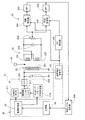
図2に示すように、信号発生部21は、予め設定された振幅および周波数の基準信号を発生する基準信号発生器211と、擬似ランダムノイズ信号であるPN(Pseudo Noise)信号を発生するPN信号発生器212と、電圧制御発振器(Voltage Controlled Oscillator:以下、VCOという)213とを含んで構成されており、磁界発生部22は送信コイル221と、同調用のコンデンサ222とを含んで構成されている。そして、ワークWが検査領域12を通過するとき、前記基準信号をPN信号を用いて周波数拡散した励磁信号をVCO213から出力して磁界発生部22の送信コイル221を電流駆動し、送信コイル221によりその励磁信号に対応する交番磁界を検査領域12中に発生させるようになっている。すなわち、VCO213はPN信号発生器212と協働し拡散変調器として機能する。
As shown in FIG. 2, the
磁界検出部23は、信号発生部21および磁界発生部22と協働してワークW中の金属異物を検出するようになっており、差動接続された一対の受信コイル231、232、同調用コンデンサ233および感度調節用可変抵抗器234等からなる。この磁界検出部23は、磁界発生部22からの交番磁界のみに対しては一対の受信コイル231、232の誘起電圧が等しく平衡し、両者の差動出力がゼロになるように調整されている。
The
磁界中を通過する磁性金属には磁束密度の大きさに比例してより多くの磁束が引き寄せられ、磁界中を通過する非磁性金属にはその移動による磁束密度の変化を打ち消すような向きでうず電流が生じ、ジュール熱が消費されるという性質がある。したがって、コンベア11上のワークWが検査領域12を通過するとき、磁界検出部23の受信コイル231、232間の出力の平衡状態がくずれる。
The magnetic metal that passes through the magnetic field attracts more magnetic flux in proportion to the magnitude of the magnetic flux density, and the nonmagnetic metal that passes through the magnetic field swirls in such a direction as to cancel the change in the magnetic flux density due to the movement. An electric current is generated and Joule heat is consumed. Therefore, when the workpiece W on the
磁界検出部23は、このようにコンベア11上のワークWの移動により両受信コイル231、232間の出力平衡状態がくずれたとき、その磁界の変化に応じた検出信号を出力する。この検出信号は、磁界発生部22側からの交番磁界に対応して前記送信信号の設定周波数を有する交流信号成分に、ワークWの磁界通過により変化する低周波信号成分が重畳した信号形態となる。
When the output balanced state between the receiving
磁界検出部23の検出信号は、信号処理部24に取り込まれるようになっている。この信号処理部24は、図2に示すように、直交検波を行なうとともに逆拡散変調器の機能を発揮する一対の同期検波器241、242と、同期検波器241、242からの検波出力信号からノイズ成分を除去する一対のバンドパスフィルタ(帯域通過フィルタ;図中ではBPF)243、244と、一対の同期検波器241、242に逆拡散変調および復調のために取り込む送信信号(基準信号を周波数拡散した信号)の位相を調整する90°移相器245と、図示しない増幅器およびA/D変換器等を含む受信レベル測定部246とによって構成されている。
The detection signal of the magnetic
信号処理部24の一対の同期検波器241、242は、直交検波のために前記送信信号を一方に、これとは90°位相が異なるよう調整した信号を他方に取り込み、それぞれ検出信号から送信信号相当の高周波成分を取り除いた検波出力を生成するとともに、検波に際して拡散信号成分を掛け合わすことで逆拡散処理を施すことになる。信号処理部24は、この検波出力に更にバンドパスフィルタ243、244によるノイズ除去やA/D変換等を施した信号を金属有無判定部26と検出制御回路30とにそれぞれ出力する。
The pair of
なお、前記直交検波の出力は、例えば、磁束密度変化が大きいほど外部磁界変化を引き起こす非磁性金属の影響が大きい検出信号、又は/及び磁束密度が大きいほど外部磁界変化を引き起こす磁性金属の影響の大きい検出信号となる。また、信号処理部24から出力される低周波成分の検出信号は、例えば差動検出信号の所定位相位置の瞬時値を結ぶ包絡線の波形、および前記所定位相位置から送信信号周期の1/4周期分、つまり90°だけ位相がずれた瞬時値を結ぶ包絡線の波形を形成するものとなる。
The output of the quadrature detection is, for example, a detection signal in which the influence of a nonmagnetic metal causing an external magnetic field change is larger as the magnetic flux density change is larger, and / or the influence of a magnetic metal causing an external magnetic field change is larger as the magnetic flux density is larger. Large detection signal. The low-frequency component detection signal output from the
検出制御回路30は、磁界検出部23の検出信号およびユーザーの設定操作入力に基づいて所定の制御プログラムに従った演算処理を実行し、その処理結果に応じて信号発生部21および磁界検出部23にそれぞれ制御信号を出力するようになっている。
The
具体的なハードウェア構成を図示しないが、検出制御回路30は、例えばCPU、RAM、ROMおよびI/Oインターフェースを含むマイクロコンピュータで構成可能なものであり、ROM内に格納された制御プログラムをRAMとの間でデータの授受を行ないながらCPUにより実行し、I/Oインターフェースを介して取り込んだ信号処理部24からの信号等に基づいて、後述する処理を実行するようになっている。この検出制御回路30は、機能的には、図1に示す基準設定部31、発信制御部32、磁界検出制御部33、記憶部34(記憶手段)および拡散条件選択部35を実現するようになっている。
Although a specific hardware configuration is not illustrated, the
信号発生部21の発生信号の振幅および基準信号周波数は基準設定部31により設定され、信号発生部21からの送信信号はPN信号発生器212からのPN信号を用いてVCO213で周波数拡散される。ここで、PN信号発生器212は発信制御部32からの指令入力される所定のM系列の擬似ランダムノイズ符号(拡散符号)に対応するPN信号を発生するようになっている。すなわち、ここでのPN信号は、基準信号のビットレートより小さいチップレートと基準信号の周期より十分に長い所定の周期とを有しており、拡散符号は、例えばCh.1「101011001000111」、Ch.2「100011110101100」、Ch.3「100100011110101」という形で与えられる。
The amplitude and reference signal frequency of the signal generated by the
すなわち、発信制御部32は、PN信号発生器212と協働して、信号発生部21で発生する励磁信号をPN信号(所定の拡散条件、所定の拡散符号)を用いて周波数拡散する機能と、その拡散条件を切り替えることのできる拡散条件切替手段の機能とを有しており、磁界検出制御部33は、ワーク検知センサ13の検知情報に応じてワークWが検査領域に進入するときに磁界検出部23を作動させる機能と、信号処理部24と共同して検査領域中のワークWの移動による交番磁界の変動に対応する信号を前記所定の拡散条件に従い逆拡散して前記検出信号を生成させる機能(後述する)とを有する磁界検出制御手段となっている。
That is, the
また、拡散条件選択部35は、発信制御部32で使用される拡散条件を例えば複数の選択肢のうちからユーザーが選択操作入力することのできる設定入力器を含み、予め記憶部34に記憶された複数の拡散条件うち任意の1つの拡散条件を選択して発信制御部32による拡散条件を指定することができる手段(拡散条件選択手段)となっている。この拡散条件選択部35は、後述するように、起動時やメンテナンスモード時に外来ノイズを検出した結果に基づいて、使用環境に好適な拡散条件を選択して発信制御部32による拡散条件を指定する機能を併有している。
The diffusion
また、発信制御部32は、基準設定部31で設定された基準信号の設定条件を基にその設定された振幅および周波数の基準信号を信号発生部21の基準信号発生器211により発生させる一方、信号発生部21で使用する拡散条件、例えば拡散符号の内容を記憶部34から読み出し、その拡散符号に対応するPN信号を信号発生部21のPN信号発生器212に発生させるようになっている。
The
磁界検出制御部33は、信号処理部24の同期検波器241、242に対し前記拡散された励磁信号に対応する検波クロック信号を供給するとともに、ワーク検知センサ13がワークWの検査領域12内への進入を検知したとき、所定時間の間、信号処理部24による信号処理を実行させるようになっている。なお、この磁界検出制御部33は、基準信号発生器211およびPN信号発生器212から直接信号を入力し、磁界発生部22の作動の有無(磁界発生の有無)に関係なく、磁界検出部23の検出動作周波数を規定できるようにするようにしてもよい。
The magnetic field
記憶部34はRAM又は他の書き換え可能なメモリデバイスで構成されており、通常動作時の基準信号の周波数や振幅をはじめとして、複数の擬似ランダムノイズ符号パターン、金属検出に関する他の各種設定情報や信号処理部24での測定結果のデータを一時的に格納することができる。
The
なお、金属有無判定部26は、検査領域12に搬送された各ワークWの検出信号振幅レベルを予め定めた閾値レベルと比較し、ワークW中に金属異物が含まれているか否か、すなわち製品としての合否を公知の判定方法で判定して、その判定結果を表示部27に出力する判定手段となっている。この金属有無判定部26は、併せて、コンベア11の検査領域12より下流側に設けられた選別部28に対し、不良品を良品と分けるための選別指令信号を出力するようになっている。
The metal presence /
次に、動作について説明する。 Next, the operation will be described.
本実施形態の金属検出装置の起動時には、電源投入により、制御系の初期化と設定データの読込等が実行され、例えば磁界発生部22で発生する送信信号の基準信号の振幅や設定周波数が決定され、これに応じた交番磁界が周波数拡散を伴って磁界発生部22から発生されることになるが、この起動時又はメンテナンスモードにおいて、本実施形態では、次に述べるような拡散条件の選択設定の処理が実行される。
When the metal detection apparatus according to the present embodiment is activated, the control system is initialized and the setting data is read by turning on the power. For example, the reference signal amplitude and setting frequency of the transmission signal generated by the
図3は、その拡散条件の選択設定処理の概略手順を示すフローチャートである。 FIG. 3 is a flowchart showing a schematic procedure of the diffusion condition selection setting process.
同図において、まず、最初に金属検出装置の動作状態が、起動ボタンが押された直後の初期設定中であるか又はリセットボタンが操作された後の再設定中であるかがチェックされ(ステップS1)、そのいずれかの場合であれば(ステップS1でYESの場合)、次いで、今回の設定処理後に検査されるワークW(被検査物)の種別情報がユーザーによる設定入力又は既設定データから把握されて取得され(ステップS2)、そのワークWに関連する各種設定パラメータ等が記憶部34その他のメモリデバイスから読み込まれる(ステップS3)。
In the figure, first, it is checked whether the operation state of the metal detecting device is in the initial setting immediately after the start button is pressed or in the reset state after the reset button is operated (step S1) If any of these cases (YES in step S1), then the type information of the workpiece W (inspected object) to be inspected after the current setting process is obtained from the setting input by the user or the already set data. It is grasped and acquired (step S2), and various setting parameters related to the workpiece W are read from the
次いで、ワークWの種別情報に基づいて、ワークW中の金属検出に適した磁界周波数が設定されるとともに、拡散符号選択処理のため複数の拡散符号、例えば予め準備されたCh.1〜Ch.3の拡散符号が切替使用可能な状態にされる(ステップS4)。 Next, a magnetic field frequency suitable for metal detection in the workpiece W is set based on the type information of the workpiece W, and a plurality of spreading codes, for example, Ch.1 to Ch. 3 spread codes can be switched (step S4).
そして、ワークWに好適な検査周波数帯域で、例えばCh.1〜Ch.3の順に使用する拡散符号が選択されて(ステップS5)、まず最初の拡散符号を用いた場合における外来電磁ノイズのノイズレベルが測定され(ステップS6)、測定結果が記憶部34に一時的に記憶される(ステップS7)。なお、外来ノイズ測定時には、磁界発生部22からの送信信号レベルを5分の1程度以下に抑える、例えば磁界検出部23側での検出レベルを実質的にゼロ(許容ノイズレベル以下)にして、磁界発生部22からの影響を十分に小さくする。
Then, spread codes to be used in the order of Ch.1 to Ch.3, for example, are selected in the inspection frequency band suitable for the work W (step S5), and the noise of the external electromagnetic noise when the first spread code is used first. The level is measured (step S6), and the measurement result is temporarily stored in the storage unit 34 (step S7). At the time of external noise measurement, the transmission signal level from the
次いで、今回の測定結果が許容ノイズレベル判定のための閾値である所定値の電磁ノイズレベル以下となっているか否かが判別され(ステップS8)、所定値以下のノイズレベルであれば(ステップS8でYESの場合)、今回のチェックに使用した拡散符号をそのまま選択設定して、これを以後の動作中における周波数拡散のPN信号発生に適用する(ステップS11)。 Next, it is determined whether or not the current measurement result is equal to or lower than a predetermined electromagnetic noise level that is a threshold for determining an allowable noise level (step S8). If the noise level is equal to or lower than the predetermined value (step S8). If YES, the spreading code used for the current check is selected and set as it is, and this is applied to the generation of a PN signal for frequency spreading during the subsequent operation (step S11).
今回の測定結果が所定値以下の磁界ノイズレベルでなければ(ステップS8でNOの場合)、次いで、ステップS5に戻って次の拡散符号の選択を行ない、その拡散条件で再度、検査領域12中への外来電磁ノイズのノイズレベルが測定され(ステップS6)、その測定結果が記憶部34に一時的に記憶される(ステップS7)。
If the current measurement result is not a magnetic field noise level equal to or lower than the predetermined value (NO in step S8), the process returns to step S5 to select the next spreading code, and again in the
このような処理が、拡散条件の異なる2つ又は3つの拡散符号についで実施されると、通常は、その間に測定結果は所定の電磁ノイズレベル以下となり、拡散符号選択設定は完了する。 When such a process is performed next to two or three spreading codes having different spreading conditions, the measurement result usually falls below a predetermined electromagnetic noise level during that time, and the spreading code selection setting is completed.
上記の処理が所定回数内で繰り返し実行されても測定結果が所定値の電磁ノイズレベル以下とならなければ(ステップS9でYESの場合)、電磁ノイズ異常であることを表示、プリント又は音声その他の出力形式で報知し(ステップS10)、次いで、測定結果のうち電磁ノイズレベルが最も低い拡散符号を選択して、以後の検出動作に使用する拡散符号を決定する(ステップS11)。 Even if the above processing is repeatedly executed within a predetermined number of times, if the measurement result does not fall below the predetermined electromagnetic noise level (YES in step S9), it is indicated that the electromagnetic noise is abnormal, print or voice or other Announcement is made in the output format (step S10), and then the spreading code with the lowest electromagnetic noise level is selected from the measurement results, and the spreading code used for the subsequent detection operation is determined (step S11).
このような拡散符号の選択設定が済むと、次いで、磁界発生部22の発生磁界強度が通常の検出動作時の出力レベルに設定され(ステップS12)、ワークWについての金属検出が可能な状態となる。なお、電磁ノイズ異常の場合に、ユーザーが何らかの操作入力を行なうまで、待機状態とすることもできる。
After such selection of the spreading code is completed, the magnetic field intensity generated by the
上述の設定が完了すると、外来ノイズの影響を抑えた検出条件下で、通常の金属検出が可能となる。 When the above setting is completed, normal metal detection is possible under detection conditions in which the influence of external noise is suppressed.
図4は、拡散符号の相違による相互干渉の抑制効果を説明する相関図であり、同図(a)はCh.1とCh.2の相関関係を、同図(b)はCh.1とCh.3の相関関係を、同図(c)は隣接する金属検出装置間で同一の拡散符号Ch.1を用いた場合の相関関係を示している。同図(c)に示すように、同一拡散符号の装置間では相関ピーク値(=1)が存在するため、隣接する金属検出装置が発生する同一符号で周波数拡散した送信信号を受信したときに干渉が生じるが、同図(a)又は同図(b)に示すように、異なる拡散符号間では相関値が小さくなり、相互干渉が生じ難いことがわかる。すなわち、Ch.1の拡散符号を用いて拡散した信号を受信しても、その受信信号は逆拡散によってCh.1の拡散符号とは異なるCh.2やCh.3の拡散符号によって周波数拡散され、許容ノイズレベルを超えるような検出信号出力としては現れず、実質的に相互干渉が無いことになる。 4 is a correlation diagram for explaining the effect of suppressing mutual interference due to the difference in spreading codes. FIG. 4A shows the correlation between Ch.1 and Ch.2, and FIG. 4B shows the correlation between Ch.1 and Ch.1. The correlation of Ch. 3 shows the correlation when the same spreading code Ch. 1 is used between adjacent metal detection devices. As shown in FIG. 5C, there is a correlation peak value (= 1) between devices with the same spreading code, so when a transmission signal spread by the same code generated by an adjacent metal detection device is received. Although interference occurs, as shown in FIG. 6A or FIG. 6B, it can be seen that the correlation value is small between different spreading codes, and mutual interference hardly occurs. That is, even if a signal spread using a Ch.1 spreading code is received, the received signal is frequency-spread by a spreading code of Ch.2 or Ch.3 different from the spreading code of Ch.1 by despreading. The detection signal output exceeding the allowable noise level does not appear and there is substantially no mutual interference.
本実施の形態においては、所定の拡散条件で拡散された励磁信号に応じて磁界発生部22から磁界が発生し、ワークWがその交番磁界中を通過することに起因する交番磁界の変動が、磁界検出部23で検出されるときに選択設定された所定の拡散条件に従い逆拡散がされて、前記検出信号が生成される。したがって、拡散によって外来電磁ノイズの影響を受け難くすることができる。
In the present embodiment, a magnetic field is generated from the magnetic
しかも、ワークWに対し使用磁界の好ましい周波数帯域内で、相互干渉を抑えるように拡散符号が相互に異なるように選択設定されることになるので、例えばワークWに好適な同じ検査周波数帯域(数十kHz〜数MHzの帯域から、例えば200kHz帯、400kHz帯というように選択設定することができる)を使用した複数の金属検出装置が近接配置されるような場合でも、複数の擬似ランダムノイズ符号のうち異なる擬似ランダムノイズ符号を用いることで、隣接する装置間での干渉を確実に抑えることができ、それら複数の金属検出装置の使用磁界周波数を微調整するような手間を軽減することができる。 Moreover, since the spreading codes are selected and set differently within the preferred frequency band of the magnetic field used for the work W so as to suppress mutual interference, for example, the same inspection frequency band (several numbers suitable for the work W) Even in the case where a plurality of metal detectors using a band of 10 kHz to several MHz can be selected and set, such as a 200 kHz band and a 400 kHz band), a plurality of pseudo random noise codes By using different pseudo-random noise codes, interference between adjacent devices can be reliably suppressed, and the trouble of finely adjusting the magnetic field frequency of the plurality of metal detection devices can be reduced.
[第2の実施の形態] [Second Embodiment]
図5は、本発明の第2の実施の形態に係る金属検出装置の検出系の概略構成図である。なお、本実施形態の金属検出装置の構成は上述の実施の形態とほぼ同様であるので、上述と同一又は類似の構成要素および処理については上述と同一の符号を用いて説明する。 FIG. 5 is a schematic configuration diagram of a detection system of the metal detection device according to the second embodiment of the present invention. In addition, since the structure of the metal detection apparatus of this embodiment is as substantially the same as the above-mentioned embodiment, it demonstrates using the same code | symbol as the above about the component and process which are the same as that of the above, or similar.
本実施形態の金属検出装置においては、信号発生部21が互いに排他的な設定周波数帯域を持つ複数のランプ波形信号(図6参照)のうち任意の1つのランプ波形により基準信号を拡散変調した送信信号(送信コイル221の励磁信号)を生成するとともに、磁界検出部23および信号処理部24がワークWの通過により変動する検査領域中の交番磁界に対応する検出信号を前記選択した何れかのランプ波形信号に基づき逆拡散処理して検出信号を生成するようになっている。
In the metal detection device of the present embodiment, the
図5に示すように、信号発生部21は、予め設定された振幅および周波数の基準信号を発生する基準信号発生器211と、基準信号より十分に周期の短いのこぎり波形の電圧信号であるランプ波形信号を発生するランプ波形発生器216と、基準信号発生器211からの基準信号をランプ波形発生器216からのランプ波形に応じて拡散変調した送信信号を出力するVCO213とを含んで構成されている。そして、ワークWが検査領域12を通過するとき、VCO213からの送信信号出力により磁界発生部22の送信コイル221を電流駆動し、送信コイル221によりその送信信号(励磁信号)に対応する交番磁界を検査領域12中に発生させるようになっている。すなわち、VCO213はランプ波形発生器216と協働する拡散変調器を構成している。
As shown in FIG. 5, the
また、拡散条件選択部35で選択される前記複数種の拡散条件は、記憶部34に排他的な設定周波数帯域を持つ複数のランプ波形信号を特定するパラメータ群として予め記憶格納されている。そして、拡散条件選択部35は、発信制御部32で使用される拡散条件を記憶部34に記憶された複数の選択肢(複数のランプ波形信号)のうちからユーザーが選択操作入力することのできる設定入力器を含み、予め記憶部34に記憶された複数の拡散条件うち任意の1つの拡散条件を選択して発信制御部32による拡散条件を指定することができる拡散条件選択手段となっている。
The plurality of types of diffusion conditions selected by the diffusion
この拡散条件選択部35は、後述するように、起動時やメンテナンスモード時に外来ノイズを検出した結果に基づいて、上述の実施形態と同様な手順で使用環境に好適な拡散条件を何れかのランプ波形信号として選択し、発信制御部32による拡散条件を指定する機能を併有している。
As will be described later, the diffusion
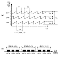
図6(a)は、ランプ波形発生器216からVCO213に与えられるランプ波形群の一例について、それぞれの入力電圧の時間による変化を示している。上述した排他的な設定周波数帯域は、同図においては、各帯域の特定のランプ波形の周期T1、T2、T3の相違(例えばT1<T2<T3)およびVCO入力電圧(VCOに入力される周波数掃引信号電圧)の差として現れている。すなわち、各チャンネルCh.1〜Ch.3の波形についてみると、それぞれの周期Tが異なるとともに、周波数拡散の帯域に対応するVCO入力電圧の帯域が掃引帯域Vs1、Vs2、Vs3のように電圧方向にオフセットすることで、各チャネルCh.1〜Ch.3の排他性が確保されている。勿論、チャンネルCh.1〜Ch.3のランプ波形について、それらの周期T1〜T3を異ならせる場合に掃引帯域Vsを同一帯域(例えば図6(a)中に示す最大拡散帯域Vmに設定できる)に設定しても拡散効果は得られるし、チャンネルCh.1〜Ch.3のランプ波形の掃引帯域VsをVs1〜Vs3のように異ならせる場合(すなわち、チャンネル毎に異なる拡散周波数帯域を設定する場合)にそれらを同一の周期Tに設定しても拡散効果は得られる。
FIG. 6A shows a change of each input voltage with respect to an example of a ramp waveform group given from the
図6に示す例では、チャンネルCh.1〜Ch.3で規定される周波数帯は、それぞれワーク特性に応じた検査周波数の周波数バンド内に含まれるように設定され、例えば図6(b)に例示する特定のワークに好適な周波数バンドA内におけるチャンネルch1a、ch2a、ch3aのように、あるいは周波数バンドB内におけるチャンネルch1b、ch2b、ch3b若しくは周波数バンドC内におけるチャンネルch1c、ch2c、ch3cのように、わずかに設定周波数の異なる独立した周波数帯となっている。このように、近似する形状であるが設定周波数がわずかに異なる複数のランプ波形と、ランプ波形が周波数帯が異なり相互に近似していない複数のランプ波形とを、ワークの特性や使用する装置台数等に応じて適宜選択することができるようなっている。 In the example shown in FIG. 6, the frequency bands defined by the channels Ch.1 to Ch.3 are set so as to be included in the frequency band of the inspection frequency corresponding to the work characteristics, for example, as shown in FIG. As in the channels ch1a, ch2a, ch3a in the frequency band A suitable for the specific work illustrated, or in the channels ch1b, ch2b, ch3b in the frequency band B or channels ch1c, ch2c, ch3c in the frequency band C Independent frequency bands with slightly different set frequencies. In this way, the characteristics of the workpiece and the number of devices to be used are a plurality of ramp waveforms that have an approximate shape but a slightly different set frequency, and a plurality of ramp waveforms that have different frequency bands and are not approximate to each other. It can be appropriately selected according to the above.
このように構成された本実施形態の金属検出装置では、磁界発生手段の励磁信号が互いに設定周波数の異なるランプ波形信号の何れかに応じて拡散変調および逆拡散変調されることから、外来電磁ノイズの影響を受け難くなる。 In the metal detection device of the present embodiment configured as described above, the excitation signal of the magnetic field generating means is subjected to diffusion modulation and despread modulation in accordance with any one of the ramp waveform signals having different setting frequencies. It becomes difficult to be affected by.
また、排他的な設定周波数帯域を持つ複数のランプ波形信号を選択して使用することで、上述の実施形態と同様に、金属検出装置を複数並設した場合でも、複数の拡散条件のうち相互に異なる拡散条件として、隣接する装置間での干渉を無くすことができる。すなわち、図6に示すように、チャンネルCh.1〜Ch.3のランプ波形入力について、それらの周期T1〜T3および掃引帯域Vs1〜Vs3をそれぞれ相違させることで、外来ノイズ抑制効果と干渉抑圧効果を共に確保することができる。 In addition, by selecting and using a plurality of ramp waveform signals having exclusive set frequency bands, even when a plurality of metal detection devices are arranged in parallel, as in the above-described embodiment, each of the plurality of diffusion conditions is As a different diffusion condition, interference between adjacent devices can be eliminated. That is, as shown in FIG. 6, with respect to the ramp waveform input of channels Ch.1 to Ch.3, the periods T1 to T3 and the sweep bands Vs1 to Vs3 are made different from each other, so that the external noise suppression effect and the interference suppression effect Can be secured together.
なお、チャンネルCh.1〜Ch.3のランプ波形入力について、それらの周期T1〜T3を異ならせるだけで、掃引帯域Vsを同一帯域とした異種拡散パターンの場合にも、それによって互いの相関が小さくなって干渉し難くなる。この場合、同調回路の帯域幅により最大拡散帯域Vmが制限されるものの、各チャンネルの拡散帯域幅を最大拡散帯域Vmと同一の値まで大きく設定できるという利点があるから、ノイズ抑制効果が優れたものとなる。一方、チャンネルCh.1〜Ch.3のランプ波形入力の掃引帯域VsをVs1〜Vs3のように異ならせるだけで同一の周期Tを設定した場合にも、掃引帯域Vs1〜Vs3に対応してVCO213の発振周波数帯域が排他的となることから、隣接する装置間での干渉を確実に抑制することができるという利点がある。
In addition, regarding the ramp waveform input of the channels Ch.1 to Ch.3, the correlation between each other can be obtained even in the case of different types of diffusion patterns in which the sweep band Vs is the same band only by changing their periods T1 to T3. Smaller and less likely to interfere. In this case, although the maximum spreading band Vm is limited by the bandwidth of the tuning circuit, there is an advantage that the spreading band width of each channel can be set to the same value as the maximum spreading band Vm, so that the noise suppression effect is excellent. It will be a thing. On the other hand, when the same period T is set by merely changing the sweep band Vs of the ramp waveform input of channels Ch.1 to Ch.3 as Vs1 to Vs3, the
いずれの場合にも、本実施形態における拡散帯域幅は、送信コイル221と同調コンデンサ222とからなる同調回路のQ(周波数選択性の良さを表わす同調特性値)に基づいて決定される。具体的には、全周波数帯を数kHz〜数MHzの範囲のうち複数の周波数帯とし、例えば1MHz帯に対応する同調回路のQの値が100であれば、1MHz帯における周波数拡散の拡散帯域幅(=f/Q)は10kHzといった形で設定される。
In any case, the spreading bandwidth in the present embodiment is determined based on the Q (tuning characteristic value representing good frequency selectivity) of the tuning circuit composed of the
[第3の実施の形態] [Third embodiment]
図7は、本発明の第3の実施の形態に係る金属検出装置の検出系の概略構成図である。なお、本実施形態の金属検出装置の構成は上述の各実施の形態とほぼ同様であるので、上述と同一又は類似の構成要素および処理については上述と同一の符号を用いて説明する。 FIG. 7 is a schematic configuration diagram of a detection system of the metal detection device according to the third embodiment of the present invention. In addition, since the structure of the metal detection apparatus of this embodiment is as substantially the same as each above-mentioned embodiment, it demonstrates using the code | symbol same as the above about the component and process which are the same as that of the above, or similar.
本実施形態の金属検出装置においては、図7に示すように、信号発生部21が、ワークWに適した検出動作周波数を設定可能な基準周波数発生器211と、周波数拡散を行なうための周波数シンセサイザ217およびホッピングパターン符号発生器218とで構成されており、周波数シンセサイザ217はホッピングパターン符号発生器218と協働する拡散変調器の機能を有している。
In the metal detector of the present embodiment, as shown in FIG. 7, the
具体的には、発信制御部32からの選択指令入力に従って、ホッピングパターン符号発生器218は指定されたホッピングパターン符号の信号を出力する。このホッピングパターン符号発生器218から周波数シンセサイザ217に対して送られる信号は、互いに排他的なホッピング周波数およびホッピングパターンの周波数ホッピング動作を指定する複数チャンネル(例えば図8(a)中のCh.1〜Ch.3)のうち任意のチャンネルの符号出力である。
Specifically, in accordance with a selection command input from
これにより、例えば、図8に示すチャンネルCh.1のホッピングパターンが選択された場合には、周波数シンセサイザ217から出力される合成信号は、その周波数がf7、f4、f1、f7、f4、f1という繰返し順序で順次異なる周波数に切り替えられ、周波数ホッピングにより拡散された信号となる。次のチャンネルCh.2のホッピングパターンの場合には、周波数がf2、f8、f5、f2、f8、f5という順序で、更に次のチャンネルCh.3のホッピングパターン場合には、周波数がf9、f6、f3、f9、f6、f3という順序で、それぞれ周波数が順次切り替えれられることで、同様の周波数拡散がなされる。また、周波数シンセサイザ217から出力される拡散された信号に対応してVCO213から送信信号が出力される。
Thereby, for example, when the hopping pattern of the channel Ch.1 shown in FIG. 8 is selected, the frequency of the synthesized signal output from the
そして、VCO213からの送信信号出力により磁界発生部22の送信コイル221が電流駆動され、その送信信号(励磁信号)に対応する交番磁界を検査領域12中に発生させる。
Then, the
また、磁界検出制御部33により制御される磁界検出部23および信号処理部24、具体的には同期検波器241、242が、ワークWの通過により変動する検査領域中の交番磁界に対応する検出信号を、前記選択した何れかのホッピングパターン符号に基づき逆拡散処理して検出信号を生成する。
Further, the magnetic
拡散条件選択部35で選択される前記複数種の拡散条件は、記憶部34に排他的なホッピング周波数およびホッピングパターンを持つ複数のホッピングパターン符号群として予め記憶格納されている。そして、拡散条件選択部35は、発信制御部32で使用される拡散条件を記憶部34に記憶された複数の選択肢(複数のランプ波形信号)のうちからユーザーが選択操作入力することのできる設定入力器を含み、予め記憶部34に記憶された複数の拡散条件うち任意の1つの拡散条件を選択して発信制御部32による拡散条件を指定することができる拡散条件選択手段となっている。
The plurality of types of spreading conditions selected by the spreading
また、拡散条件選択部35は、後述するように、起動時やメンテナンスモード時に外来ノイズを検出した結果に基づいて、図3に示した上述の実施形態の拡散条件の選択設定手順と同様な手順で、使用環境に好適な拡散条件を何れか1チャンネルのホッピングパターン符号として選択し、発信制御部32による拡散条件を指定する機能を併有している。
Further, as will be described later, the diffusion
記憶部34に予め記憶される前記複数のホッピングパターンは、周波数が上述のように周期的に変化するとともに、異なるチャンネル間では周波数を共有しない設定となっているので、使用チャンネルの異なる装置間では統計的にも瞬間的にも相互干渉が生じない。
In the plurality of hopping patterns stored in advance in the
このように構成された本実施形態の金属検出装置においては、周波数拡散の方式が上述の実施形態とは異なるものの、磁界発生手段の励磁信号が互いにホッピング周波数およびホッピングパターンの異なる複数のチャンネルCh.1〜Ch.3のホッピングパターン符号の何れかに応じて拡散変調および逆拡散変調がなされることで、外来電磁ノイズの影響を受け難くなる。また、排他的なホッピング周波数およびホッピングパターンを持つ複数のチャンネルのホッピングパターン符号を排他的に選択設定することで、上述の実施形態と同様に、金属検出装置を複数並設した場合でも、複数の拡散条件のうち相互に異なる拡散条件で、隣接する装置間での干渉を生じ難くすることができる。 In the metal detection device of this embodiment configured as described above, although the frequency spreading method is different from that of the above-described embodiment, the excitation signals of the magnetic field generating means have a plurality of channels Ch. Having different hopping frequencies and hopping patterns. The spread modulation and the despread modulation are performed according to any one of 1 to Ch.3 hopping pattern codes, so that it is difficult to be affected by external electromagnetic noise. In addition, by exclusively selecting and setting hopping pattern codes of a plurality of channels having exclusive hopping frequencies and hopping patterns, even when a plurality of metal detection devices are arranged in parallel as in the above-described embodiment, Interference between adjacent devices can be made difficult to occur under different diffusion conditions among the diffusion conditions.
なお、上述した各実施形態の金属検出装置は、周波数逆拡散機能と検波機能を兼ね備えた同期検波器を採用したものであったが、本発明の金属検出装置はこれに限らず、例えば磁界検出部23と検波部を構成する信号処理部24との間に独立した逆拡散変調器を挿入し、これにより拡散符号と同一の逆拡散符号を用いて逆拡散処理を行なう等することで、逆拡散機能と検波機能と別個の構成要素で分担する構成とすることができるのはいうまでもない。また、拡散条件選択設定処理における測定結果を記憶部34に一時的に記憶するだけでなく蓄積しておき、外来電磁ノイズの変化を経時的に比較可能な情報とすることもできる。
In addition, although the metal detection apparatus of each embodiment mentioned above employ | adopted the synchronous detector which had a frequency despreading function and a detection function, the metal detection apparatus of this invention is not restricted to this, For example, a magnetic field detection An independent despreading modulator is inserted between the
以上説明したように、本発明は、所定の拡散条件で拡散された励磁信号に応じて磁界発生手段から磁界を発生させるとともに、被検査体がその交番磁界中を通過することに起因する交番磁界の変動を検出する磁界検出手段に、前記所定の拡散条件に従う逆拡散を行なって検出信号を生成させ、かつ、複数種の拡散条件のうち任意の1つの拡散条件を選択して所定の拡散条件を切替可能に設定するようにしているので、拡散によって外来電磁ノイズの影響を受け難くするとともに、金属検出装置を複数並設した場合でもその拡散条件を互いに相違させるよう設定することができ、隣接する装置間で干渉し難い金属検出装置を提供することができるという効果を奏するものであり、被検査体中の金属又は金属成分を検出する金属検出装置、特に食品等の被検査体が磁界中を通過するときの磁界の変動を基に被検査体中における金属又は金属成分の有無を判定する金属検出装置全般に有用である。 As described above, the present invention generates a magnetic field from the magnetic field generating means according to the excitation signal diffused under a predetermined diffusion condition, and the alternating magnetic field due to the inspected object passing through the alternating magnetic field. A detection signal is generated by performing despreading according to the predetermined diffusion condition, and any one diffusion condition among a plurality of types of diffusion conditions is selected and the predetermined diffusion condition is detected. Can be set to be switchable, so that it is difficult to be affected by external electromagnetic noise due to diffusion, and even when a plurality of metal detection devices are arranged in parallel, the diffusion conditions can be set to be different from each other. It is possible to provide a metal detection device that is unlikely to interfere with each other, and a metal detection device that detects a metal or a metal component in an object to be inspected, particularly food. The object to be inspected is useful for determining the metal detecting device in general the presence of metal or metal component in the object to be inspected in the basis of the variation of the magnetic field as it passes through the magnetic field and the like.
12 検査領域
13 ワーク検知センサ
20 検出部
21 信号発生部(磁界発生手段)
22 磁界発生部(磁界発生手段)
23 磁界検出部(磁界検出手段)
24 信号処理部(磁界検出手段、検波部)
26 金属有無判定部(判定手段)
27 表示部
28 選別部
30 検出制御回路
31 基準設定部
32 発信制御部(拡散条件切替手段)
33 磁界検出制御部
34 記憶部(記憶手段)
35 拡散条件選択部(周波数選択設定手段)
12
22 Magnetic field generator (magnetic field generator)
23 Magnetic field detection part (magnetic field detection means)
24 Signal processing unit (magnetic field detection means, detection unit)
26 Metal presence / absence determination unit (determination means)
27
33 Magnetic field
35 Diffusion condition selection unit (frequency selection setting means)
Claims (5)
前記被検査体が前記検査領域中を通過することに起因する前記交番磁界の変動を検出する磁界検出手段(23、24)と、
該磁界検出手段の検出信号に基づいて前記被検査体中における金属物又は金属成分の有無を判定する判定手段(26)とを備えた金属検出装置において、
前記磁界発生手段が前記周波数バンド内で設定された所定の拡散条件で前記励磁信号を拡散する機能を有するとともに、前記磁界検出手段が前記交番磁界の変動に対応する信号を前記所定の拡散条件に従い逆拡散して前記検出信号を生成する機能を有し、
複数種の拡散条件のうち任意の1つの拡散条件を選択して前記所定の拡散条件を設定する拡散条件選択手段(35)と、
該拡散条件選択手段の選択結果に応じて、前記磁界発生手段および前記磁界検出手段でそれぞれ使用する前記所定の拡散条件を切り替える拡散条件切替手段(32)と、を設けたことを特徴とする金属検出装置。 A magnetic field generating means for antibody originating in an alternating magnetic field of the set frequency bands according to the characteristics of the object to be inspected, a predetermined inspection area in accordance with the excitation signal (12) (21, 22),
Wherein the magnetic field detection means for detecting the variation of the alternating field inspection object is caused by passing through the said examination region (23, 24),
In a metal detection apparatus comprising a determination means (26) for determining the presence or absence of a metal object or a metal component in the inspection object based on a detection signal of the magnetic field detection means,
The magnetic field generation means has a function of diffusing the excitation signal under a predetermined diffusion condition set within the frequency band, and the magnetic field detection means outputs a signal corresponding to the fluctuation of the alternating magnetic field according to the predetermined diffusion condition. A function of generating the detection signal by despreading;
A diffusion condition selection means (35) for selecting any one diffusion condition among a plurality of types of diffusion conditions and setting the predetermined diffusion condition;
Metal having a diffusion condition switching means (32) for switching the predetermined diffusion conditions respectively used by the magnetic field generation means and the magnetic field detection means in accordance with a selection result of the diffusion condition selection means Detection device.
前記拡散条件選択手段で選択される前記複数種の拡散条件が、前記励磁信号のビットレートより小さいチップレートと所定の周期とを有する複数の擬似ランダムノイズ符号で規定されることを特徴とする請求項1に記載の金属検出装置。 The magnetic field generating means spreads the frequency of the excitation signal using a predetermined spreading code, and the magnetic field detecting means reverses the detection signal corresponding to the fluctuation of the alternating magnetic field using the same despreading code as the spreading code. Diffusing to generate the detection signal,
The plurality of types of diffusion conditions selected by the diffusion condition selection means are defined by a plurality of pseudo random noise codes having a chip rate smaller than a bit rate of the excitation signal and a predetermined period. Item 2. The metal detection device according to Item 1.
前記拡散符号選択手段で選択される前記複数種の拡散条件が、異なる複数のホッピングパターンで規定されることを特徴とする請求項1に記載の金属検出装置。 The magnetic field generation means frequency hops modulates the excitation signal with a predetermined hopping pattern, and the magnetic field detection means generates a detection signal by frequency hopping modulating a detection signal corresponding to the fluctuation of the alternating magnetic field with the hopping pattern. And
The metal detection apparatus according to claim 1, wherein the plurality of types of diffusion conditions selected by the spreading code selection unit are defined by a plurality of different hopping patterns.
前記拡散条件選択手段で選択される前記複数種の拡散条件が、前記排他的な設定周波数を持つ複数のランプ波形信号で規定されることを特徴とする請求項1に記載の金属検出装置。 The magnetic field generating means diffuses and modulates the excitation signal by any one selected from a plurality of ramp waveform signals having mutually exclusive set frequencies, and the magnetic field detecting means generates a detection signal corresponding to the fluctuation of the alternating magnetic field. The detection signal is generated by despreading based on any of the selected ramp waveform signals,
2. The metal detection apparatus according to claim 1, wherein the plurality of types of diffusion conditions selected by the diffusion condition selection unit are defined by a plurality of ramp waveform signals having the exclusive set frequency.
Priority Applications (1)
| Application Number | Priority Date | Filing Date | Title |
|---|---|---|---|
| JP2005023437A JP4137893B2 (en) | 2005-01-31 | 2005-01-31 | Metal detector |
Applications Claiming Priority (1)
| Application Number | Priority Date | Filing Date | Title |
|---|---|---|---|
| JP2005023437A JP4137893B2 (en) | 2005-01-31 | 2005-01-31 | Metal detector |
Publications (2)
| Publication Number | Publication Date |
|---|---|
| JP2006208291A JP2006208291A (en) | 2006-08-10 |
| JP4137893B2 true JP4137893B2 (en) | 2008-08-20 |
Family
ID=36965305
Family Applications (1)
| Application Number | Title | Priority Date | Filing Date |
|---|---|---|---|
| JP2005023437A Active JP4137893B2 (en) | 2005-01-31 | 2005-01-31 | Metal detector |
Country Status (1)
| Country | Link |
|---|---|
| JP (1) | JP4137893B2 (en) |
Families Citing this family (7)
| Publication number | Priority date | Publication date | Assignee | Title |
|---|---|---|---|---|
| US9326705B2 (en) | 2009-09-01 | 2016-05-03 | Adidas Ag | Method and system for monitoring physiological and athletic performance characteristics of a subject |
| US9545222B2 (en) | 2009-09-01 | 2017-01-17 | Adidas Ag | Garment with noninvasive method and system for monitoring physiological characteristics and athletic performance |
| US9526419B2 (en) | 2009-09-01 | 2016-12-27 | Adidas Ag | Garment for physiological characteristics monitoring |
| US20110050216A1 (en) * | 2009-09-01 | 2011-03-03 | Adidas Ag | Method And System For Limiting Interference In Magnetometer Fields |
| WO2012174745A1 (en) * | 2011-06-24 | 2012-12-27 | Siemens Aktiengesellschaft | Apparatus used for detecting metal, metal detection apparatus and method, and vehicle detector |
| JP6557700B2 (en) * | 2017-04-27 | 2019-08-07 | アンリツインフィビス株式会社 | Metal detector |
| EP3553477B1 (en) * | 2018-04-13 | 2020-10-14 | Ontech Security, S.L. | Disturbance measurement apparatus in a controlled magnetic field |
-
2005
- 2005-01-31 JP JP2005023437A patent/JP4137893B2/en active Active
Also Published As
| Publication number | Publication date |
|---|---|
| JP2006208291A (en) | 2006-08-10 |
Similar Documents
| Publication | Publication Date | Title |
|---|---|---|
| JP4137893B2 (en) | Metal detector | |
| JP4633830B2 (en) | Metal detector | |
| CA1231152A (en) | Method and system for detecting an indicating device | |
| DE60139387D1 (en) | DEVICE AND METHOD FOR METAL DETECTION | |
| KR900005621B1 (en) | Inspecting instrument for iron mixed in materials | |
| US10036797B2 (en) | Electron spin resonance apparatus | |
| JP3662841B2 (en) | Metal detector | |
| JP4141987B2 (en) | Metal detector | |
| JP4879219B2 (en) | Ground detector | |
| JP3658523B2 (en) | Metal detector | |
| JP4854228B2 (en) | Axle detection device | |
| JP2003167064A (en) | Metal detector | |
| JP4145883B2 (en) | Metal detector | |
| KR930700924A (en) | Coin testing method and apparatus | |
| JP6557700B2 (en) | Metal detector | |
| RU2216028C2 (en) | Metal detector | |
| JP2000314776A (en) | Metal detector | |
| JP2007315837A (en) | Metal detecting apparatus and method thereof | |
| KR20100121191A (en) | Foreign metal object detecting apparatus in food and a detecting method | |
| US11762118B2 (en) | Metal detection apparatus | |
| RU2412486C1 (en) | Method of authenticating banknotes, bond paper and documents | |
| JPH10209838A (en) | Supervisory system, measurement system and measurement device | |
| US7714990B2 (en) | Hand-held laser distance measuring device with a pulse reflection mixing method | |
| JP2006023138A (en) | Electronic circuit inspection apparatus and electronic circuit inspection method | |
| JPH01254857A (en) | Eddy current flaw detector |
Legal Events
| Date | Code | Title | Description |
|---|---|---|---|
| A977 | Report on retrieval |
Free format text: JAPANESE INTERMEDIATE CODE: A971007 Effective date: 20070830 |
|
| A131 | Notification of reasons for refusal |
Free format text: JAPANESE INTERMEDIATE CODE: A131 Effective date: 20080325 |
|
| A521 | Request for written amendment filed |
Free format text: JAPANESE INTERMEDIATE CODE: A523 Effective date: 20080430 |
|
| TRDD | Decision of grant or rejection written | ||
| A01 | Written decision to grant a patent or to grant a registration (utility model) |
Free format text: JAPANESE INTERMEDIATE CODE: A01 Effective date: 20080603 |
|
| A01 | Written decision to grant a patent or to grant a registration (utility model) |
Free format text: JAPANESE INTERMEDIATE CODE: A01 |
|
| A61 | First payment of annual fees (during grant procedure) |
Free format text: JAPANESE INTERMEDIATE CODE: A61 Effective date: 20080604 |
|
| R150 | Certificate of patent or registration of utility model |
Ref document number: 4137893 Country of ref document: JP Free format text: JAPANESE INTERMEDIATE CODE: R150 Free format text: JAPANESE INTERMEDIATE CODE: R150 |
|
| FPAY | Renewal fee payment (event date is renewal date of database) |
Free format text: PAYMENT UNTIL: 20110613 Year of fee payment: 3 |
|
| FPAY | Renewal fee payment (event date is renewal date of database) |
Free format text: PAYMENT UNTIL: 20120613 Year of fee payment: 4 |
|
| R250 | Receipt of annual fees |
Free format text: JAPANESE INTERMEDIATE CODE: R250 |
|
| FPAY | Renewal fee payment (event date is renewal date of database) |
Free format text: PAYMENT UNTIL: 20120613 Year of fee payment: 4 |
|
| FPAY | Renewal fee payment (event date is renewal date of database) |
Free format text: PAYMENT UNTIL: 20130613 Year of fee payment: 5 |
|
| R250 | Receipt of annual fees |
Free format text: JAPANESE INTERMEDIATE CODE: R250 |
|
| R250 | Receipt of annual fees |
Free format text: JAPANESE INTERMEDIATE CODE: R250 |
|
| R250 | Receipt of annual fees |
Free format text: JAPANESE INTERMEDIATE CODE: R250 |
|
| R250 | Receipt of annual fees |
Free format text: JAPANESE INTERMEDIATE CODE: R250 |
|
| S533 | Written request for registration of change of name |
Free format text: JAPANESE INTERMEDIATE CODE: R313533 |
|
| R350 | Written notification of registration of transfer |
Free format text: JAPANESE INTERMEDIATE CODE: R350 |
|
| R250 | Receipt of annual fees |
Free format text: JAPANESE INTERMEDIATE CODE: R250 |
|
| R250 | Receipt of annual fees |
Free format text: JAPANESE INTERMEDIATE CODE: R250 |
|
| R250 | Receipt of annual fees |
Free format text: JAPANESE INTERMEDIATE CODE: R250 |
|
| R250 | Receipt of annual fees |
Free format text: JAPANESE INTERMEDIATE CODE: R250 |
|
| R250 | Receipt of annual fees |
Free format text: JAPANESE INTERMEDIATE CODE: R250 |
|
| R250 | Receipt of annual fees |
Free format text: JAPANESE INTERMEDIATE CODE: R250 |
|
| S111 | Request for change of ownership or part of ownership |
Free format text: JAPANESE INTERMEDIATE CODE: R313111 |
|
| R350 | Written notification of registration of transfer |
Free format text: JAPANESE INTERMEDIATE CODE: R350 |
|
| R250 | Receipt of annual fees |
Free format text: JAPANESE INTERMEDIATE CODE: R250 |
|
| R250 | Receipt of annual fees |
Free format text: JAPANESE INTERMEDIATE CODE: R250 |