JP4124885B2 - Image playback device - Google Patents
Image playback device Download PDFInfo
- Publication number
- JP4124885B2 JP4124885B2 JP30032098A JP30032098A JP4124885B2 JP 4124885 B2 JP4124885 B2 JP 4124885B2 JP 30032098 A JP30032098 A JP 30032098A JP 30032098 A JP30032098 A JP 30032098A JP 4124885 B2 JP4124885 B2 JP 4124885B2
- Authority
- JP
- Japan
- Prior art keywords
- image
- button
- display
- reproduction
- displayed
- Prior art date
- Legal status (The legal status is an assumption and is not a legal conclusion. Google has not performed a legal analysis and makes no representation as to the accuracy of the status listed.)
- Expired - Fee Related
Links
Images


Description
【0001】
【発明の属する技術分野】
本発明は、画像再生装置に関する。
【0002】
【従来の技術】
従来、静止画像を再生する画像再生装置や画像撮像再生装置の中には、一定時間、利用者の操作が加えられない場合、自動的に装置の電源を切ったり、あるいは再生用のモニタの電源だけを切ったりする機能を有するものがあった。
【0003】
実際に利用者が電源を切るのを忘れて装置を放置してしまった場合、無駄に電力が消費されてしまうことを防止するこの機能は利用者にとって有益な機能であった。
【0004】
【発明が解決しようとする課題】
しかしながら、上記従来の画像再生装置や画像撮像再生装置では、以下に掲げる問題があり、その改善が要望されていた。すなわち、このような画像再生装置や画像撮像再生装置は静止画像の自動再生機能を有しており、自動再生の実行中、利用者は自動再生を一時停止するといった操作、あるいは中止するといった操作以外、装置に対して操作を加えることがなかった。
【0005】
したがって、自動再生中に一定時間、操作が加えられないことにより、利用者が実際に自動再生された画像を見ているにもかかわらず、電源が切れてしまうという問題があった。
【0006】
そこで、本発明は、スライドショー再生する際、利用者が一定時間、操作せずに自動再生された画像を見ている時に電源が切れてしまう不具合を解消することができる画像再生装置を提供することを目的とする。
【0007】
【課題を解決するための手段】
上記目的を達成するために、本発明の画像再生装置は、利用者によって操作される操作手段と、前記操作手段の操作が所定期間行われていないか否かを判別する操作状態判別手段と、前記操作が所定期間行われていないと判別された場合、電源を遮断する電源遮断手段とを備えた画像再生装置において、前記操作手段を操作することなく記録されている画像を自動的に順次再生する自動再生状態または前記操作手段を操作することで記録されている画像を順次再生する手動再生状態のいずれかでスライドショー再生するスライドショー再生手段と、前記手動再生状態にてスライドショー再生される場合には、前記操作状態判別手段および前記電源遮断手段を動作させるように制御するとともに、前記自動再生状態にてスライドショー再生される場合には、前記操作状態判別手段および前記電源遮断手段を動作させないように制御する制御手段とを備えたことを特徴とする。
【0019】
【発明の実施の形態】
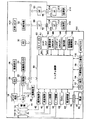
本発明の画像再生装置の実施の形態について説明する。本実施形態の画像再生装置は電子カメラに適用される。図1は実施の形態における電子カメラの構成を示すブロック図である。図において、100は画像処理装置である。10は撮影レンズ、12は絞り機能を有するシャッタ、14は光学像を電気信号に変換する撮像素子、16は撮像素子14から出力されるアナログ信号をディジタル信号に変換するA/D変換器である。
【0020】
18は撮像素子14、A/D変換器16およびD/A変換器26にクロック信号や制御信号を供給するタイミング発生回路であり、メモリ制御回路22およびシステム制御回路50によって制御される。
【0021】
20は画像処理回路であり、A/D変換器16からのデータあるいはメモリ制御回路22からのデータに対して所定の画素補間処理や色変換処理を行う。画像処理回路20は撮像された画像データを用いて所定の演算処理を行い、得られた演算結果に基づき、システム制御回路50が露光制御部40および測距制御部42を制御するためのTTL(スルー・ザ・レンズ)方式のAF(オートフォーカス)処理、AE(自動露出)処理およびEF(フラッシュプリ発光)処理を行っている。また、画像処理回路20は、撮像された画像データを用いて所定の演算処理を行い、得られた演算結果に基づいてTTL方式のAWB(オートホワイトバランス)処理を行っている。
【0022】
22はメモリ制御回路であり、A/D変換器16、タイミング発生回路18、画像処理回路20、画像表示メモリ24、D/A変換器26、メモリ30および圧縮・伸長回路32を制御する。
【0023】
A/D変換器16からのデータは、画像処理回路20およびメモリ制御回路22を介して、あるいは直接、メモリ制御回路22を介して画像表示メモリ24あるいはメモリ30に書き込まれる。
【0024】
24は画像表示メモリ、26はD/A変換器である。28はTFT方式のLCDからなる画像表示部である。画像表示メモリ24に書き込まれた表示用の画像データはD/A変換器26を介して画像表示部28に表示される。画像表示部28で撮像された画像データを逐次表示する場合、電子ファインダ機能を実現することが可能である。また、画像表示部28はシステム制御回路50の指示にしたがって表示のON/OFFを任意に行うことが可能であり、表示をOFFにした場合、画像処理装置100の電力消費を大幅に低減することができる。
【0025】
30は撮影された静止画像や動画像を格納するためのメモリであり、所定枚数の静止画像や所定時間の動画像を格納するのに十分な記憶容量を有している。したがって、複数枚の静止画像を連続して撮影する連写撮影やパノラマ撮影の場合にも、高速かつ大量の画像書き込みをメモリ30に対して行うことが可能である。また、メモリ30はシステム制御回路50の作業領域としても使用することが可能である。
【0026】
32は適応離散コサイン(ADCT)などにより画像データを圧縮伸長する圧縮・伸長回路であり、メモリ30に格納された画像を読み込んで圧縮処理あるいは伸長処理を行い、処理を終えたデータをメモリ30に書き込む。これらのデータは後述する記録媒体に、画像データを取り込んだ際の情報、例えば撮影日時、連写、パノラマ撮影等の情報とともに格納される。
【0027】
40は絞り機能を有するシャッタ12を制御する露光制御部であり、フラッシュ部48と連携することによりフラッシュ調光機能を有する。42は撮影レンズ10のフォーカシングを制御する測距制御部である。44は撮影レンズ10のズーミングを制御するズーム制御部である。46はバリアである保護部102の動作を制御するバリア制御部である。48はフラッシュ部であり、AF補助光の投光機能、フラッシュ調光機能を有する。
【0028】
露光制御部40および測距制御部42はTTL方式を用いて制御されており、前述したように、撮像された画像データを用いて画像処理回路20により演算された演算結果に基づき、システム制御回路50が露光制御部40および測距制御部42を制御する。
【0029】
50は画像処理装置100全体を制御するシステム制御回路であり、周知のCPUなどを内蔵する。52はシステム制御回路50の動作用の定数、変数、プログラムなどを記憶するメモリである。54はシステム制御回路50でのプログラムの実行に応じて、文字、画像、音声などで動作状態やメッセージなどを表示する液晶表示装置、スピーカなどを有する表示部であり、画像処理装置100の操作部近辺の視認し易い単数あるいは複数箇所に設置される。表示部54は、LCD、LED、発音素子などの組合わせにより構成されている。また、表示部54の一部の機能は光学ファインダ104内に設けられている。
【0030】
表示部54の表示内容のうち、LCDなどに表示するものとしては、シングルショット/連写撮影表示、セルフタイマ表示、圧縮率表示、記録画素数表示、記録枚数表示、残撮影可能枚数表示、シャッタスピード表示、絞り値表示、露出補正表示、フラッシュ表示、赤目緩和表示、マクロ撮影表示、ブザー設定表示、時計用電池残量表示、電池残量表示、エラー表示、複数桁の数字による情報表示、記録媒体200、210の着脱状態表示、通信I/F動作表示、日付・時刻表示などがある。
【0031】
また、表示部54の表示内容のうち、光学ファインダ104内に表示するものとしては、合焦表示、手振れ警告表示、フラッシュ充電表示、シャッタスピード表示、絞り値表示、露出補正表示などがある。
【0032】
56は電気的に消去・記録可能な不揮発性メモリであり、不揮発性メモリとしてEEPROMなどが用いられる。60、62、64、66、68および70はシステム制御回路50の各種動作指示を入力するための操作部であり、スイッチ、ダイヤル、タッチパネル、視線検知によるポインティング、音声認識装置などの単数あるいは複数の組み合わせで構成される。これら操作部の詳細を以下に示す。
【0033】
60はモードダイアルスイッチであり、電源オフ、自動撮影モード、撮影モード、パノラマ撮影モード、再生モード、マルチ画面再生・消去モード、PC接続モードなどの各機能モードを切り替えて設定可能である。
【0034】
62はシャッタースイッチ(SW1)であり、シャッターボタン128(図2参照)の操作途中でONとなり、AF(オートフォーカス)処理、AE(自動露出)処理、AWB(オートホワイトバランス)処理、EF(フラッシュプリ発光)処理などの動作開始を指示する。
【0035】
64はシャッタースイッチ(SW2)であり、シャッターボタン(図示せず)の操作完了でONとなる。このシャッタースイッチ(SW2)64は、撮像素子12から読み出した信号をA/D変換器16、メモリ制御回路22を介してメモリ30に画像データを書き込む露光処理、画像処理回路20やメモリ制御回路22での演算を用いた現像処理、メモリ30から画像データを読み出し、圧縮・伸長回路32で圧縮を行い、記録媒体200、201に画像データを書き込む記録処理という一連の処理の動作開始を指示する。
【0036】
66は画像表示ON/OFFスイッチであり、画像表示部28のON/OFFを設定する。この画像表示ON/OFFスイッチ66の機能により、光学ファインダ104を用いて撮影を行う際、TFT方式のLCDからなる画像表示部28への電流供給を遮断し、省電力化を図ることができる。
【0037】
68はクイックレビューON/OFFスイッチであり、撮影直後に撮影した画像データを自動再生するクイックレビュー機能を設定する。70は各種ボタンやタッチパネルなどからなる操作部であり、メニューボタン、セットボタン、マクロボタン、マルチ画面再生改ページボタン、フラッシュ設定ボタン、単写/連写/セルフタイマ切替ボタン、メニュー移動+(プラス)ボタン、メニュー移動−(マイナス)ボタン、再生画像移動+(プラス)ボタン、再生画像−(マイナス)ボタン、撮影画質選択ボタン、露出補正ボタン、日付/時間設定ボタンなどを有する。尚、本実施形態では、画像処理装置100は、これらのスイッチや操作部による入力の検出を行い、システム制御回路50によって一定期間入力が行われていないことを判断する機能を有する。
【0038】
80は電源制御部であり、電池検出回路、DC−DCコンバータ、通電するブロックを切り替えるスイッチ回路などから構成されており、電池の装着の有無、電池の種類、電池残量の検出を行い、その検出結果およびシステム制御回路50の指示に基づいてDC−DCコンバータを制御し、必要な電圧を必要な期間、記録媒体を含む各部に供給する。
【0039】
82および84はコネクタ、86はアルカリ電池やリチウム電池などの一次電池、NiCd電池、NiMH電池、Li電池などの二次電池、ACアダプタなどからなる電源部である。
【0040】
90および94はメモリカードやハードディスク等の記録媒体とのインターフェース、92および96はメモリカードやハードディスクなどの記録媒体との接続を行うコネクタ、98はコネクタ92、96に記録媒体200、210が装着されているか否かを検知する記録媒体着脱検知部である。
【0041】
尚、本実施形態では、記録媒体を取り付けるインターフェースおよびコネクタが2系統装備されているが、記録媒体を取り付けるインターフェースおよびコネクタは単数あるいは任意の数の系統数に装備された構成であってもよい。また、異なる規格のインターフェースおよびコネクタとして、PCMCIAカードやCF(コンパクトフラッシュ)カードなどの規格に準拠したものを用いてもよい。
【0042】
さらに、インターフェース90、94、コネクタ92、96をPCMCIAカードやCF(コンパクトフラッシュ)カードなどの規格に準拠したものを用いて構成した場合、LANカード、モデムカード、USBカード、IEEE1394カード、P1284カード、SCSIカード、PHSなどの通信カードなどの各種通信カードを接続することより、他のコンピュータやプリンタなどの周辺機器との間で画像データや画像データに付属した管理情報を相互に転送することが可能である。
【0043】
102は画像処理装置100の撮影レンズ10を含む撮像部を覆うことにより、撮像部の汚れや破損を防止するバリア(保護部)である。104は光学ファインダであり、画像表示部28による電子ファインダ機能を使用することなく、光学ファインダだけを用いて撮影を行うことが可能である。また、光学ファインダ104内には、表示部54の一部の機能、例えば、合焦表示、手振れ警告表示、フラッシュ充電表示、シャッタスピード表示、絞り値表示、露出補正表示などが設けられている。
【0044】
110は通信部であり、RS232C、USB、IEEE1394、P1284、SCSI、モデム、LAN、無線通信などの各種通信機能を有する。112は通信部110により画像処理装置100を他の機器と接続するコネクタ、もしくは無線通信を行う場合のアンテナである。
【0045】
200はメモリカードやハードディスクなどの記録媒体である。記録媒体200は、半導体メモリや磁気ディスクなどから構成される記録部202、画像処理装置100とのインターフェース204、および画像処理装置100との接続を行うコネクタ206を有している。210は、記録媒体200と同様、メモリカードやハードディスク等の記録媒体である。記録媒体210は、半導体メモリや磁気ディスク等から構成される記録部212、画像処理装置100とのインターフェース214、および画像処理装置100との接続を行うコネクタ216を有している。
【0046】
図2は電子カメラの外観を示す図である。図において、60は前述したモードダイアルスイッチであり、電源オフ、自動撮影モード、撮影モード、パノラマ撮影モード、シングル再生モード、マルチ画面再生・消去モード、PC接続モードなどの各機能モードを切り替えて設定することが可能である。
【0047】
128はシャッタボタンである。カメラの撮影画像が表示される画像表示部28には通常、LCD(液晶ディスプレイ)が使用される。自動再生のための編集、設定などの画面にもLCDからなる画像表示部28が使用される。
【0048】
操作部70の操作ボタンには、MENUボタン122、SETボタン121、+ボタン124、−ボタン125、JUMPボタン123などがある。これらの操作ボタンはつぎのように用いられる。
【0049】
MENUボタン122は画像記録と共用のものであり、メニュー起動、画像操作を含むメニュー階層下でMENUボタン122を押下すると、上の階層に戻る。SETボタン121は画像記録と共用のものであり、メニュー選択項目決定、画像操作の実行(ガイダンス付き)に用いられる。JUMPボタン123はマルチ格子表示での改ページに用いられる。+ボタン124は最新の画像に向かう画像移動、メニューの項目移動、スライドショーのポーズ・再開に用いられる。−ボタン125は最古の撮影画像に向かう画像移動、メニューの項目移動、スライドショーのポーズ・再開に用いられる。+ボタン124を送りボタン、−ボタン125を戻しボタンと称してもよく、これらのボタンは自動再生モードでのスライドショーのポーズ・再開用ボタンとしても用いられる。
つぎに、通常再生状態での操作について示す。
【0050】
[シングル画像再生]
図2に示すモードダイアルスイッチ60のダイアルセット位置がSingleである場合、シングル画面が起動し、Multiである場合、マルチ画面が起動し、その起動後、最新の画像(一番大きいファイル番号を持つ画像)が表示される。
【0051】
シングル画像再生では、画像を画像表示部(LCD)28の画面一杯に表示する。自分が撮影するサイズ以外の場合、フル画面の表示にはならず、余白(黒)が生じる。起動時、最新の画像を表示し、その後、+/−ボタン124、125で表示画面を前後に移動する。最後(最新)の画像で+ボタン124を押した場合、先頭(最古)の画像を表示する。先頭の画像で−ボタン125を押した場合、最後の画像を表示する。
【0052】
JUMPボタン123を押すと、ジャンプバー(図示しない)を表示する。その状態で+/−ボタン124、125を押すと、10枚先(前)の頁に移動する。再び、JUMPボタン123を押すと、通常の表示に戻る。また、ジャンプバーが表示された状態でSETボタン121を押したまま、+ボタン124を押すと、最新の画像、−ボタン124を押すと、最古の画像を表示する。
【0053】
[マルチ画像再生]
図3は画像表示部28に表示されたサムネール画像を示す図である。マルチ画像再生では、図3に示すように、サムネール画像(インデックス用の小さい画像)131を3×3の格子状に画像表示部(LCD)28の画面一杯に表示する。自分が撮影するサイズ以外の場合、フル画面の表示にはならず、余白(黒)が生じる。また、サムネール画像が表示不可能である場合、その理由を示すアイコン(図示しない)を表示する。
【0054】
起動後、最新の画像を右下に配置して表示する。但し、サムネール画像が9枚以下である場合、左上から順番にサムネール画像を表示し、改ページをしない。通常、1つの画像がカーソル132で選択され、+/−ボタンを押下することでカーソル132が移動し、選択画像を変更する。ここで、選択画像とは、メニューから入る画像操作(Erase,Protect)の最初の対象となる画像であり、選択後にシングル再生の対象となる画像である。また、画面下方に現在どこを見ているかを示すポジションバー133を表示する。
【0055】
JUMPボタン123を押すと、ポジションバー133の代わりにジャンプバー(図示しない)を表示する。その状態で+/−ボタンを押すと、次(前)の頁に移動する。再び、JUMPボタン123を押すと、カーソルが1枚の選択の表示に戻る。その際、選択されている画像は直前のオペレーションが+ボタン124である場合、改ページ後の先頭画像、−ボタン125である場合、改ページ後の最終画像、+/−ボタンが押されていない場合、元々選択されていた画像になる。
【0056】
また、ジャンプバーが表示された状態でSETボタン121を押したまま+ボタン124を押すと、最新の画像を含む画面、−ボタン125を押すと、最古の画像を含む画面を表示する。また、モードダイアルスイッチ60のMULTIとSINGLEのポジションの切り替えによって、マルチ再生とシングル再生の切り替えが可能である。
【0057】
シングル表示、マルチ表示中にMENUボタン122を押すと、PLAY(プレイ)メニュー141が表示される。図4はプレイ(再生)メニューの表示画面を示す図である。図において、142は現在表示されている再生メニューのタイトルである。144は「情報を表示」、「スライドショー」、「プロテクト」、「消去」、「設定」と表示されているメニューで選択可能な項目である。太枠143は現在選択されている項目を示す。
【0058】
また、146は直前の画像再生状態で表示されていた画像、もしくは選択されていた画像である。147は画像の属性を表現するためのアイコン、148は画像に付けられている番号である。
【0059】
+/−ボタンで項目を移動し、希望の項目にカーソルを合わせて、SETボタン121を押すことにより、それぞれの項目で定義された画像操作、カメラの設定が可能である。但し、画像が存在しない場合、「設定」の項目だけが選択可能であり、他の項目は灰色表示(図示せず)となり、選択が不可能であることを表す。
【0060】
つづいて、実際にスライドショーを実行するための設定および手順について示す。「スライドショー」の項目を+/−ボタン124、125を用いて選択し、SETボタン121を押すことにより、スライドショーメニューが表示される。図9はスライドショーメニューの表示画面を示す図である。
【0061】
スライドショーメニューの操作方法は、前述したプレイメニュー141の操作方法と同じである。図9に示すスライドメニュー181で選択可能な項目184には、タイトル182の下方に表示される「開始」、「画像のマーク」、「マークのクリア」、「再生間隔」、「リピート」の5項目がある。以下にそれぞれの項目が選択され、SETボタン121が押された際の動作を示す。
【0062】
「開始」:項目の右に「全画像」、「ショー1」、「ショー2」、「ショー3」のサブ項目が表示される。ここで、ショー1、ショー2、ショー3とは、後述する画像のマークによって、作成されるスライドショーで再生すべき、画像群の指定であり、指定がされていないものはグレーで表示されており、選択することができない。+/−ボタン124、125を用いてサブ項目を選択し、SETボタン121を押すと、スライドショーが開始される。開始されるスライドショーは後述する設定項目の内容にしたがったものである。
【0063】
「画像のマーク」:この項目では、再生可能なすべての静止画からスライドショー再生の対象となる画像を選択するための画面に移行する。この項目を選択し、SETボタン121を押すと、「ショー1」、「ショー2」、「ショー3」のサブ項目が表示される。例えば、ショー1を選択し、SETボタン121を押すと、「開始」の中の項目「ショー1」が選択された場合に再生する画像を選択するためのマーク画面になる。図10は画像のマーク画面を示す図である。
【0064】
図において、191、192は画面のタイトルであり、現在、スライドショーで再生するショー2の画像を選択する画面であることを示している。ここでは、再生可能な静止画が領域194の中に3×2のマルチ画面で表示され、このマルチ表示と同じ操作で画像を送って表示することが可能である。
【0065】
現在、選択対象となっている画像は、通常のマルチ画面と同じく、枠201で囲むことで表示されている。この枠201をカーソルと呼ぶ。また、199は現在、選択対象となっている画像に付けられた番号、196はその画像の種類を示す表示であり、この例では画像がRAWデータであることを示している。198はその画像の属性を示すアイコンである。この例では、消去防止のためのプロテクトが施され、連写で撮影された画像であり、音声情報が付加されているということを示している。この他、パノラマ撮影が行われたことを示すアイコン等が表示可能である。
【0066】
200はその画像が既にスライドショーで再生する対象として指定されていることを示すアイコン(チェックマーク)である。197はこの画面が表示されている状態で利用者がSETボタン121を押したときに実行される動作を表示して利用者の理解を促すためのガイダンスである。利用者はこの画面を用いて再生対象としてのマークすべき画像を選択し、カーソルが目的の画像にある状態でSETボタン121を押すことにより、その画像にスライドショーの再生対象としてのマークが表示される。
【0067】
そして、チェックマーク200が表示された時点でその画像はスライドショーの再生対象となり、画面右下のガイダンス197の表示は「SET取り消し」となり、この状態で再びSETボタン1210を押すと、選択状態が解除されることを示している。この画面の操作によりマークされた画像の情報は、例えばCF(コンパクトフラッシュ)等の記憶媒体に情報として残される。
【0068】
「マークのクリア」:画像マーク機能で行われた選択を解除する。この項目を選択してSETボタン121を押すと、「ショー1」、「ショー2」、「ショー3」のサブ項目が表示される。但し、マーク機能においてマークされた画像がない場合、対応する項目はグレー表示され、選択することができない。例えば、ショー1を選択してSETボタン121を押すと、ショー1でなされている画像の選択をすべて解除するか否かを確認するダイアログ(図示せず)を表示した後、解除してよいと利用者によって指定された場合、「ショー1」で指定された選択をすべて解除する。
【0069】
「再生間隔」:スライドショーの再生のための間隔を指定するための項目である。この項目を選択してSETボタン121を押すと、項目の右に「2秒」、「5秒」、「10秒」、「+・−マニュアル」のサブ項目が表示される。秒が指定された場合、スライドショーは指定された時間が過ぎた場合に自動的に次の画像を表示する。これが、いわゆる自動再生状態である。「+・−マニュアル」の項目が指定された場合、スライドショーの開始後、先頭の画像を表示し、その後、+ボタン124または−ボタン125が押された場合、次の画像または後の画像を表示する。
【0070】
「リピート」:スライドショーの再生で最後の画像を表示した後、再び先頭画像を表示する、いわゆるリピート機能を有効にするか否かを指定するための項目である。この項目を選択してSETボタン121を押すと、項目の右に「入」、「切」のサブ項目が表示される。ここで、「入」が選択されると、リピート機能が有効になる。
【0071】
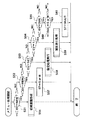
図5および図6は通常再生および自動再生を指定するための操作、および自動再生中に一定期間、利用者が操作を行わなかった場合、電源をオフにする再生処理手順を示すフローチャートである。この処理プログラムはメモリ52に格納されており、システム制御回路50内のCPUによって実行される。モードダイアルスイッチ60がシングルもしくはマルチに変更された場合、図5および図6の処理を開始する。
【0072】
まず、現在のモードダイアルスイッチ60の状態によって現在の再生動作状態を指定するための内部変数STにSingleもしくはMultiをセットする(ステップS1〜S3)。現在自動再生中であるか手動再生中であるかを判断するための内部変数FLAGに現在手動再生中であることを示すFALSEをセットする(ステップS4)。
【0073】
利用者による入力イベントを検知したか否かを判別し(ステップS5)、利用者による入力イベントを検知した場合、変数TOに現在の時刻を示す値と一定値TOVALを加算した値をセットする(ステップS6)。この一定値TOVALは何も操作されていない状態で電源をオフにするまでの時間であり、任意の値に設定可能である。
【0074】
また、検知したイベントはイベントの種類を表す変数EV(図示せず)に値としてセットされ、後述するステップS12〜S16の処理に伝えられる。ここで検知するイベントの種類としては、ボタンが押されたことを示すMENU、JUMP、+、−、SETの他、ダイアル変更が発生したことを示すDIAL等が挙げられる。
【0075】
ステップS6で変数TOに現在の時刻を示す値と一定値TOVALを加算した値をセットした後、あるいはステップS5で入力イベントが検知されなかった場合、現在の状態を指定する変数STに応じたステップS7〜S16の処理を行う。ステップS12〜S16の処理の間に発生したイベント、つまり、利用者の処理の種類に応じて、現在の機器の再生動作状態を示す変数STの変更および自動再生中であるか否かを示す変数FLAGの変更が行われる。
【0076】
その後、現在のモードダイアルスイッチ60の位置がシングルかマルチになっているか否かを判別し(ステップS17)、シングルでもマルチでもない場合、処理を終了する。一方、現在のモードダイアルスイッチ60の位置がシングルかマルチになっている場合、ステップ12〜ステップS16の処理実行前と比べて状態を示す変数STが変化しているか否かを判別し(ステップS18)、変化していた場合、状態が変化したことを示すイベントを発行する(ステップS19)。このイベントの名前をこれ以降、NEWと称する。
【0077】
そして、自動再生中であるか否かを示す変数FLAGを調べ(ステップS20)、自動再生中と判断される場合、つまり変数FLAGがTRUEになっている場合、次のステップS21の処理を行わないで、再びステップS5の処理に戻る。
【0078】
一方、変数FLAGがFALSEである場合、現在の時刻と前回のイベントが発生した際にセットした値とを比較し(ステップS21)、現在時刻がその値を越えていない場合、再び、ステップS5の処理に戻る。また一方、現在時刻がセットされた値を越えていた場合、ステップS5の処理に戻らないで処理を終了する。
【0079】
このように、メインの再生処理を終了すべき事象が発生しない限り、ステップS5〜ステップS21までの処理を繰り返す。この処理を終了した後、システム制御回路50内のCPUによって電源オフのための処理が実行され、画像表示部28の電源が遮断される。この処理による画像表示部28の電源の遮断は、画像表示ON/OFFスイッチ66をオフにすることによって行われる電源の遮断と同じである。
【0080】
図7はステップS12におけるシングル(Single)処理手順を示すフローチャートである。図5のステップS7の処理で変数STがSingleであった場合に実行される。この処理では、与えられたイベント、つまり利用者が操作した内容の種類に応じた処理を行う。まず、イベント(EV)の種類を判別し(ステップS31〜S35)、判別されたイベントの種類に応じてステップS36〜ステップS41の処理を行う。
【0081】
ステップS36は変数STが他の状態からSINGLEに移行した場合に発生する処理であり、その際に必要な画面を作成して表示するための処理である。ステップS37では、メニューボタンが押されたために変数STをMENUに変更する。ここで変更された変数STを図6のステップS11で参照し、ステップS16のメニュー(Menu)処理を実行することにより、シングル表示状態からメニュー表示状態への遷移が実現される。
【0082】
図8は変数STがMenuである場合にステップS16で実行されるメニュー(Menu)処理手順を示すフローチャートである。Single処理と同様、イベント(EV)の種類を判別し(ステップS51〜S55)、判別されたイベントの種類に応じて初期画面作成、メニュー終了、メニュー項目実行、項目送りなどの処理が実行される(ステップS56〜ステップS61)。
【0083】
図9のスライドショーメニュー181では、画像の開始(スタート)が選択されてSETボタン121が押された場合、このメニュー処理によって状態を表す変数STにSLIDEがセットされ、図6のメインの再生処理のステップS14のスライド(Slide)処理でスライドショーの処理が行われるようになる。
【0084】
図11および図12はステップS14のスライド処理において実行されるスライドショー処理手順を示すフローチャートである。発生したイベント(EV)の種類に応じて処理を振り分ける(ステップS71〜S75)。発生したイベント(EV)がNEWである場合、初期画面を作成する(ステップS76)。ここで、初期画面とは、全画像再生が指定されていた場合には一番古い画像、ショー1等の画像が指定されている場合には一番最初に指定されていた画像を表示した画面である。
【0085】
そして、自動再生であった場合、つまりスライドショーのメニュー画面で2秒、5秒、10秒が選択された場合、次の画像を再生すべき時間をセットする(ステップS77)。自動再生であるか手動再生であるかを判別し(ステップS78)、自動再生である場合、自動再生中であることを示す変数FLAGにTRUEをセットし(ステップS78)、処理を終了する。一方、手動再生である場合、そのまま終了する。
【0086】
また、発生したイベント(EV)がMENUである場合、変数FLAGをFALSEにセットし(ステップS80)、必要な終了処理を行う(ステップS81)。その後、変数STをMENUにセットする(ステップS82)。この処理によりスライドショーの終了後に状態がMENUに変更され、メインの再生処理によってイベントNEWが発行した後、MENU処理が実行され、メニューが描画される。
【0087】
さらに、発生したイベント(EV)がNONE、つまり利用者が何も操作していない場合、自動再生であるか否かを判別し(ステップS83)、自動再生でない場合、何も処理を行わず、処理を終了する。一方、ステップS83で自動再生であった場合、次の画像を再生する時間に達しているか否かを判別し(ステップS84)、達していない場合、何も処理を行わず、処理を終了する。
【0088】
一方、次の画像を再生する時間に達している場合、現在、自動再生が中断されているか否かを判別し(ステップS85)、自動再生が中断されている場合、何も処理を行わず、処理を終了する。一方、自動再生が中断されていない場合、再生対象画像の再生を完了してリピート設定もされていないか否かを判別する(ステップS86)。再生対象画像の再生を完了してリピート設定もされていない場合、スライドショーの終了処理(ステップS81)側に分岐する。一方、再生対象画像の再生を完了していない場合、あるいはリピート設定がされている場合、次に表示する画面を作成し(ステップS87)、処理を終了する。
【0089】
また、発生したイベント(EV)が+/−である場合、自動再生中であるか否かを判別し(ステップS74)、自動再生中である場合、自動再生を中断(ポーズ)するためのフラグ変数PAUSEにPAUSEを論理否定した値を代入し、処理を終了する。
【0090】
一方、自動再生中でない場合、つまり+/−マニュアル再生が指定されていた場合、ステップS86と同様の終了チェックを行う(ステップS90)。終了と判断された場合、ステップS86と同様、スライドショーの終了処理(ステップS81)側に分岐する。一方、そうでない場合、次に表示する画面を作成し(ステップS91)、処理を終了する。
【0091】
さらに、発生したイベント(EV)がDIALである場合。現在のダイアル状態を判別する(ステップS92)。現在のダイアルモードスイッチ60がSingleあるいはMultiに変更された場合、変数FLAGにFALSEをセットし(ステップS93)、セット後に終了処理を行う(ステップS94)。そして、ダイアルモードに応じた再生状態を変数STにセットする(ステップS95)。一方、ステップS92でSingleあるいはMultiでなかった場合、何もせずに処理を終了するが、この場合、前述したように、メインの再生処理のステップS17でダイアルモードスイッチ60の位置をチェックし、本再生処理を終了する。
【0092】
尚、上記実施形態では、プレイメニュー141、スライドショーメニュー181を経てスライドショーの設定によって自動再生状態が実現されたが、これに限らず、例えば、シングル、マルチ再生中に+/−ボタンを同時に押すことにより、あるいは自動再生開始用のボタンを設けることなどにより、自動再生状態を実現するようにしても構わない。
【0093】
また、撮影状態から再生状態への切り替えをダイアルモードスイッチ60の操作によって行ったが、ボタン操作に置き換えても実施可能であり、このように状態の変化のトリガは特に限定されない。
【0094】
さらに、上記実施形態では、一定時間、何も操作しないで静止画を自動再生している状態の時に電源が切れることを防止していたが、静止画の自動再生中以外に、例えば手動再生動作で画像の編集作業中に何も操作せず、じっと考えている状態の時などにも電源が切れないようにしてもよい。これにより、編集作業中に電源がオフになって表示されなくなる不具合を防止できる。
【0095】
また、再生処理を終了して電源をオフにする場合、上記実施形態のように画像表示部(LCD)28の電源だけを遮断する代わりに、電源制御部80により装置全体の電源86を遮断するようにしてもよい。
【0096】
さらに、上記実施形態では、デジタルカメラ(電子カメラ)に適用した場合を示したが、複数の機器、例えば、ホストコンピュータ、インターフェース機器、リーダ、プリンタなどから構成されるシステムに適用しても、1つの機器からなる装置、例えば、PDA(個人情報管理)機器のような小型の画像処理機器に適用してもよい。
【0097】
また、本発明はシステムあるいは装置にプログラムを供給することによって達成される場合にも適用できることはいうまでもない。この場合、本発明を達成するためのソフトウェアによって表されるプログラムを格納した記憶媒体をシステムあるいは装置に読み出すことによってそのシステムあるいは装置が本発明の効果を享受することが可能となる。
【0098】
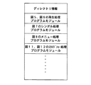
図13は記憶媒体としてのメモリ52のメモリマップを示す説明図である。メモリ52には、図5および図6の再生処理プログラムモジュール、図7のシングル(Single)処理プログラムモジュール、図8のメニュー(Menu)処理プログラムモジュール、図11および図12のスライドショー処理プログラムモジュールなどが格納されている。
【0099】
プログラムモジュールを供給する記憶媒体としては、ROMなどのメモリの他、例えばフロッピーディスク、ハードディスク、光ディスク、光磁気ディスク、CD−ROM、CD−R、DVD、磁気テープ、不揮発性のメモリカードなどを用いることができる。
【0100】
また、システム制御部内のCPU(コンピュータ)が読み出したプログラムコードを実行することにより、前述した実施形態の機能が実現されるだけでなく、そのプログラムコードの指示に基づいて、コンピュータ上で稼動しているOS(オペレーティングシステム)などが実際の処理の一部または全部を行い、その処理によって前述した実施の形態の機能が実現される場合も含まれる。
【0101】
【発明の効果】
本発明の画像再生装置によれば、スライドショー再生する際、利用者が一定時間、操作せずに自動再生された画像を見ている状態の時などに電源が切れてしまう不具合を解消することができる。
【図面の簡単な説明】
【図1】実施の形態における電子カメラの構成を示すブロック図である。
【図2】電子カメラの外観を示す図である。
【図3】画像表示部28に表示されたサムネール画像を示す図である。
【図4】プレイ(再生)メニューの表示画面を示す図である。
【図5】通常再生および自動再生を指定するための操作、および自動再生中に一定期間、利用者が操作を行わなかった場合、電源をオフにする再生処理手順を示すフローチャートである。
【図6】図5につづく、通常再生および自動再生を指定するための操作、および自動再生中に一定期間、利用者が操作を行わなかった場合、電源をオフにする再生処理手順を示すフローチャートである。
【図7】ステップS12におけるシングル(Single)処理手順を示すフローチャートである。
【図8】変数STがMenuである場合にステップS16で実行されるメニュー(Menu)処理手順を示すフローチャートである。
【図9】スライドショーメニューの表示画面を示す図である。
【図10】画像のマーク画面を示す図である。
【図11】ステップS14のスライド処理において実行されるスライドショー処理手順を示すフローチャートである。
【図12】図11につづく、ステップS14のスライド処理において実行されるスライドショー処理手順を示すフローチャートである。
【図13】記憶媒体としてのメモリ52のメモリマップを示す説明図である。
【符号の説明】
28 画像表示部
50 システム制御回路
52 メモリ
60 モードダイアルスイッチ
80 電源制御部
86 電源[0001]
BACKGROUND OF THE INVENTION
The present invention provides an image reproduction device.In placeRelated.
[0002]
[Prior art]
2. Description of the Related Art Conventionally, some image reproducing devices and image capturing / reproducing devices that reproduce still images automatically turn off the device when a user operation is not performed for a certain period of time, or turn off the power of a monitor for reproduction. Some have the function of cutting only.
[0003]
If the user forgets to turn off the power and the device is left unattended, this function that prevents unnecessary power consumption is a useful function for the user.
[0004]
[Problems to be solved by the invention]
However, the above-described conventional image reproducing apparatus and image capturing / reproducing apparatus have the following problems, and improvements have been demanded. In other words, such an image playback device or image capturing / playback device has an automatic playback function of a still image, and during the execution of the automatic playback, the user performs an operation other than an operation of pausing or canceling the automatic playback. No operation was performed on the device.
[0005]
Therefore, there is a problem that the power is turned off even though the user is actually viewing the automatically reproduced image because no operation is performed for a certain period of time during automatic reproduction.
[0006]
Therefore, the present invention providesWhen playing a slideshowAn image playback device that can solve the problem of turning off the power when a user is watching an automatically played image without operating for a certain period of time.PlaceThe purpose is to provide.
[0007]
[Means for Solving the Problems]
In order to achieve the above object, an image reproduction device of the present invention includes an operation unit operated by a user, an operation state determination unit that determines whether or not the operation of the operation unit is not performed for a predetermined period, When it is determined that the operation has not been performed for a predetermined period of time, in an image reproduction device including a power shut-off means for shutting off the power,Slideshow playback in either an automatic playback state in which recorded images are automatically played back sequentially without operating the operating means, or in a manual playback state in which recorded images are played back sequentially by operating the operating means When the slide show is played back in the manual playback state and the slide show is played back in the automatic playback state, the operation state determination means and the power shut-off means are controlled to operate. Includes a control for controlling the operation state determination means and the power shut-off means not to operate.Means.
[0019]
DETAILED DESCRIPTION OF THE INVENTION
Image reproduction apparatus of the present inventionSetEmbodiments will be described. The image reproducing apparatus of this embodiment is applied to an electronic camera. FIG. 1 is a block diagram illustrating a configuration of an electronic camera according to an embodiment. In the figure,
[0020]
A
[0021]
An
[0022]
A
[0023]
Data from the A /
[0024]
[0025]
[0026]
A compression /
[0027]
[0028]
The
[0029]
[0030]
Among the display contents of the
[0031]
Among the display contents of the
[0032]
[0033]
[0034]
A shutter switch (SW1) 62 is turned on during the operation of the shutter button 128 (see FIG. 2), and AF (auto focus) processing, AE (automatic exposure) processing, AWB (auto white balance) processing, EF (flash) Instructs the start of operations such as (pre-flash) processing.
[0035]
[0036]
[0037]
[0038]
[0039]
[0040]
90 and 94 are interfaces with a recording medium such as a memory card or a hard disk, 92 and 96 are connectors for connecting to a recording medium such as a memory card or a hard disk, and 98 is a
[0041]
In this embodiment, two interfaces and connectors for attaching the recording medium are provided. However, the interface and connector for attaching the recording medium may be provided in a single or an arbitrary number of systems. Further, as interfaces and connectors of different standards, those compliant with standards such as PCMCIA cards and CF (compact flash) cards may be used.
[0042]
Further, when the
[0043]
[0044]
A
[0045]
[0046]
FIG. 2 is a diagram showing the appearance of the electronic camera. In the figure,
[0047]
[0048]
The operation buttons of the
[0049]
The
Next, an operation in the normal reproduction state will be described.
[0050]
[Single image playback]
When the dial setting position of the
[0051]
In single image reproduction, the image is displayed on the full screen of the image display unit (LCD) 28. If it is a size other than the size to be photographed, the full screen is not displayed and a margin (black) is generated. At startup, the latest image is displayed, and then the display screen is moved back and forth with the +/−
[0052]
When the
[0053]
[Multi-image playback]
FIG. 3 is a diagram showing a thumbnail image displayed on the
[0054]
After startup, the latest image is displayed at the bottom right. However, if the number of thumbnail images is nine or less, the thumbnail images are displayed in order from the upper left, and page breaks are not performed. Normally, one image is selected by the
[0055]
When the
[0056]
When the +
[0057]
When the
[0058]
[0059]
By moving the item with the +/− button, moving the cursor to the desired item, and pressing the
[0060]
Next, settings and procedures for actually executing a slide show will be described. By selecting the item “Slide Show” using the +/−
[0061]
The operation method of the slide show menu is the same as the operation method of the
[0062]
“Start”: Sub-items “all images”, “show 1”, “show 2”, and “show 3” are displayed to the right of the item. Here, show 1, show 2 and
[0063]
“Image Mark”: In this item, the screen shifts to a screen for selecting an image to be reproduced as a slide show from all reproducible still images. When this item is selected and the
[0064]
In the figure,
[0065]
Currently, the image to be selected is displayed by surrounding it with a
[0066]
[0067]
When the
[0068]
“Clear Mark”: Cancels the selection made with the image mark function. When this item is selected and the
[0069]
“Reproduction interval”: an item for designating an interval for reproducing a slide show. When this item is selected and the
[0070]
“Repeat”: an item for designating whether or not to enable a so-called repeat function for displaying the first image again after displaying the last image in the slide show reproduction. When this item is selected and the
[0071]
5 and 6 are flowcharts showing an operation for designating normal reproduction and automatic reproduction, and a reproduction processing procedure for turning off the power when the user does not perform an operation for a certain period during automatic reproduction. This processing program is stored in the
[0072]
First, Single or Multi is set to the internal variable ST for designating the current reproduction operation state according to the state of the current mode dial switch 60 (steps S1 to S3). FALSE indicating that manual regeneration is currently being performed is set in an internal variable FLAG for determining whether automatic regeneration or manual regeneration is currently performed (step S4).
[0073]
It is determined whether or not an input event by the user is detected (step S5), and when an input event by the user is detected, a value obtained by adding a value indicating the current time and a constant value TOVAL is set to the variable TO ( Step S6). The constant value TOVAL is a time until the power is turned off in a state where nothing is operated, and can be set to an arbitrary value.
[0074]
The detected event is set as a value in a variable EV (not shown) indicating the type of the event, and is transmitted to the processing in steps S12 to S16 described later. Examples of event types to be detected include MENU, JUMP, +,-, and SET indicating that the button is pressed, and DIAL indicating that a dial change has occurred.
[0075]
After setting a value indicating the current time and a constant value TOVAL to the variable TO in step S6, or if no input event is detected in step S5, a step corresponding to the variable ST specifying the current state The process of S7-S16 is performed. A variable indicating whether or not the variable ST indicating the playback operation state of the current device is being changed and the automatic playback is being performed according to the event that occurred during the processing of steps S12 to S16, that is, the type of processing of the user. The FLAG is changed.
[0076]
Thereafter, it is determined whether or not the current position of the
[0077]
Then, a variable FLAG indicating whether or not automatic reproduction is being performed is checked (step S20). If it is determined that automatic reproduction is being performed, that is, if the variable FLAG is TRUE, the processing of the next step S21 is not performed. Thus, the process returns to step S5 again.
[0078]
On the other hand, if the variable FLAG is FALSE, the current time is compared with the value set when the previous event occurred (step S21), and if the current time does not exceed the value, the process returns to step S5. Return to processing. On the other hand, if the current time exceeds the set value, the process ends without returning to the process of step S5.
[0079]
In this way, the process from step S5 to step S21 is repeated unless an event that should end the main reproduction process occurs. After completing this process, the CPU in the
[0080]
FIG. 7 is a flowchart showing a single processing procedure in step S12. This is executed when the variable ST is Single in the process of step S7 in FIG. In this process, a process corresponding to the given event, that is, the type of content operated by the user is performed. First, the type of event (EV) is discriminated (steps S31 to S35), and the processing of step S36 to step S41 is performed according to the discriminated event type.
[0081]
Step S36 is processing that occurs when the variable ST shifts to SINGLE from another state, and is processing for creating and displaying a necessary screen at that time. In step S37, since the menu button is pressed, the variable ST is changed to MENU. A transition from the single display state to the menu display state is realized by referring to the variable ST changed here in step S11 in FIG. 6 and executing the menu (Menu) process in step S16.
[0082]
FIG. 8 is a flowchart showing the menu (Menu) processing procedure executed in step S16 when the variable ST is Menu. Similar to the single process, the type of event (EV) is determined (steps S51 to S55), and processes such as initial screen creation, menu end, menu item execution, and item feed are executed according to the determined event type. (Step S56 to Step S61).
[0083]
In the
[0084]
11 and 12 are flowcharts showing a slide show processing procedure executed in the slide processing in step S14. The processing is distributed according to the type of event (EV) that has occurred (steps S71 to S75). If the generated event (EV) is NEW, an initial screen is created (step S76). Here, the initial screen is a screen displaying the oldest image when all-image playback is specified, and the first specified image when an image such as show 1 is specified. It is.
[0085]
If it is automatic reproduction, that is, if 2 seconds, 5 seconds, or 10 seconds is selected on the menu screen of the slide show, the time for reproducing the next image is set (step S77). Whether automatic reproduction or manual reproduction is determined (step S78). If automatic reproduction is performed, TRUE is set in a variable FLAG indicating that automatic reproduction is being performed (step S78), and the process ends. On the other hand, in the case of manual regeneration, the process is terminated as it is.
[0086]
If the generated event (EV) is MENU, the variable FLAG is set to FALSE (step S80), and necessary termination processing is performed (step S81). Thereafter, the variable ST is set to MENU (step S82). By this process, the state is changed to MENU after the end of the slide show, and after the event NEW is issued by the main reproduction process, the MENU process is executed and the menu is drawn.
[0087]
Furthermore, when the generated event (EV) is NONE, that is, when the user is not operating anything, it is determined whether or not automatic reproduction is performed (step S83). End the process. On the other hand, if the automatic reproduction is performed in step S83, it is determined whether or not the time for reproducing the next image has been reached (step S84). If not, no processing is performed and the processing is terminated.
[0088]
On the other hand, if it is time to reproduce the next image, it is determined whether or not automatic reproduction is currently interrupted (step S85). If automatic reproduction is interrupted, no processing is performed. The process ends. On the other hand, if the automatic reproduction is not interrupted, it is determined whether or not the reproduction of the reproduction target image is completed and the repeat setting is not performed (step S86). If the reproduction of the reproduction target image has been completed and no repeat setting has been made, the process branches to the slide show end process (step S81). On the other hand, if the reproduction of the reproduction target image has not been completed, or if repeat setting has been made, a screen to be displayed next is created (step S87), and the process ends.
[0089]
If the generated event (EV) is +/−, it is determined whether or not automatic reproduction is in progress (step S74). If automatic reproduction is in progress, a flag for interrupting (pausing) automatic reproduction. A value obtained by logically negating PAUSE is substituted for variable PAUSE, and the process is terminated.
[0090]
On the other hand, when automatic reproduction is not being performed, that is, when +/- manual reproduction is designated, an end check similar to step S86 is performed (step S90). If it is determined to end, the process branches to the slide show end process (step S81) as in step S86. On the other hand, if not, a screen to be displayed next is created (step S91), and the process ends.
[0091]
Furthermore, the event (EV) that occurred is DIAL. The current dial state is determined (step S92). When the current
[0092]
In the above embodiment, the automatic playback state is realized by setting the slide show via the
[0093]
In addition, although switching from the shooting state to the playback state is performed by operating the
[0094]
Furthermore, in the above-described embodiment, the power is prevented from being turned off when the still image is automatically reproduced without any operation for a certain period of time. Thus, no operation may be performed during the image editing operation, and the power may not be turned off even when the user is still thinking. Thereby, it is possible to prevent a problem that the power is turned off during the editing work and the display is not displayed.
[0095]
Further, when the reproduction process is finished and the power is turned off, the power
[0096]
Furthermore, in the above-described embodiment, the case where the present invention is applied to a digital camera (electronic camera) has been shown. However, even if the present invention is applied to a system including a plurality of devices such as a host computer, an interface device, a reader, and a printer, You may apply to the apparatus which consists of one apparatus, for example, a small image processing apparatus like a PDA (personal information management) apparatus.
[0097]
Needless to say, the present invention can also be applied to a case where the present invention is achieved by supplying a program to a system or apparatus. In this case, the system or apparatus can enjoy the effects of the present invention by reading the storage medium storing the program represented by the software for achieving the present invention into the system or apparatus.
[0098]
FIG. 13 is an explanatory diagram showing a memory map of the
[0099]
As a storage medium for supplying the program modules, for example, a floppy disk, a hard disk, an optical disk, a magneto-optical disk, a CD-ROM, a CD-R, a DVD, a magnetic tape, a nonvolatile memory card, etc. are used in addition to a memory such as a ROM. be able to.
[0100]
Further, by executing the program code read out by the CPU (computer) in the system control unit, not only the functions of the above-described embodiment are realized, but also the computer is operated on the computer based on the instruction of the program code. A case where the OS (operating system) or the like performs part or all of the actual processing and the functions of the above-described embodiments are realized by the processing is also included.
[0101]
【The invention's effect】
The present inventionPaintingAccording to the image reproduction device,When playing a slideshowIt is possible to solve the problem that the power is turned off when the user is watching the automatically played image without operating for a certain period of time..
[Brief description of the drawings]
FIG. 1 is a block diagram illustrating a configuration of an electronic camera according to an embodiment.
FIG. 2 is a diagram illustrating an appearance of an electronic camera.
FIG. 3 is a diagram illustrating a thumbnail image displayed on the image display unit.
FIG. 4 is a diagram showing a display screen of a play (playback) menu.
FIG. 5 is a flowchart showing an operation for designating normal reproduction and automatic reproduction, and a reproduction processing procedure for turning off the power when a user does not perform an operation for a certain period during automatic reproduction.
FIG. 6 is a flowchart illustrating an operation for designating normal reproduction and automatic reproduction, and a reproduction processing procedure for turning off the power when a user does not perform an operation for a certain period during automatic reproduction, following FIG. It is.
FIG. 7 is a flowchart showing a single processing procedure in step S12.
FIG. 8 is a flowchart illustrating a menu (Menu) processing procedure executed in step S16 when a variable ST is Menu.
FIG. 9 is a diagram showing a display screen of a slide show menu.
FIG. 10 is a diagram illustrating an image mark screen.
FIG. 11 is a flowchart showing a slide show process procedure executed in the slide process of step S14.
FIG. 12 is a flowchart illustrating a slide show process procedure executed in the slide process of step S14, following FIG.
FIG. 13 is an explanatory diagram showing a memory map of a
[Explanation of symbols]
28 Image display
50 System control circuit
52 memory
60 mode dial switch
80 Power control unit
86 Power supply
Claims (1)
前記操作手段の操作が所定期間行われていないか否かを判別する操作状態判別手段と、
前記操作が所定期間行われていないと判別された場合、電源を遮断する電源遮断手段とを備えた画像再生装置において、
前記操作手段を操作することなく記録されている画像を自動的に順次再生する自動再生状態または前記操作手段を操作することで記録されている画像を順次再生する手動再生状態のいずれかでスライドショー再生するスライドショー再生手段と、
前記手動再生状態にてスライドショー再生される場合には、前記操作状態判別手段および前記電源遮断手段を動作させるように制御するとともに、前記自動再生状態にてスライドショー再生される場合には、前記操作状態判別手段および前記電源遮断手段を動作させないように制御する制御手段とを備えたことを特徴とする画像再生装置。An operation means operated by a user;
An operation state determination means for determining whether or not the operation of the operation means has not been performed for a predetermined period;
When it is determined that the operation has not been performed for a predetermined period of time, in an image reproduction device including a power shut-off means for shutting off the power,
Slideshow playback in either an automatic playback state in which recorded images are automatically played back sequentially without operating the operating means, or in a manual playback state in which recorded images are played back sequentially by operating the operating means Slideshow playback means to
When the slide show is reproduced in the manual reproduction state, the operation state determination unit and the power shut-off unit are controlled to operate. When the slide show is reproduced in the automatic reproduction state, the operation state is controlled. An image reproducing apparatus comprising: a determining unit; and a control unit that controls the power shut-off unit so as not to operate .
Priority Applications (1)
| Application Number | Priority Date | Filing Date | Title |
|---|---|---|---|
| JP30032098A JP4124885B2 (en) | 1998-10-08 | 1998-10-08 | Image playback device |
Applications Claiming Priority (1)
| Application Number | Priority Date | Filing Date | Title |
|---|---|---|---|
| JP30032098A JP4124885B2 (en) | 1998-10-08 | 1998-10-08 | Image playback device |
Publications (2)
| Publication Number | Publication Date |
|---|---|
| JP2000115675A JP2000115675A (en) | 2000-04-21 |
| JP4124885B2 true JP4124885B2 (en) | 2008-07-23 |
Family
ID=17883372
Family Applications (1)
| Application Number | Title | Priority Date | Filing Date |
|---|---|---|---|
| JP30032098A Expired - Fee Related JP4124885B2 (en) | 1998-10-08 | 1998-10-08 | Image playback device |
Country Status (1)
| Country | Link |
|---|---|
| JP (1) | JP4124885B2 (en) |
Families Citing this family (4)
| Publication number | Priority date | Publication date | Assignee | Title |
|---|---|---|---|---|
| JP2005277580A (en) * | 2004-03-23 | 2005-10-06 | Orion Denki Kk | Image recording/reproducing device |
| US7952535B2 (en) | 2005-02-20 | 2011-05-31 | Mediatek Singapore Pte Ltd | Electronic visual jockey file |
| JP5099169B2 (en) * | 2010-04-20 | 2012-12-12 | カシオ計算機株式会社 | Image display apparatus and program |
| JP5099170B2 (en) * | 2010-04-20 | 2012-12-12 | カシオ計算機株式会社 | Image display apparatus and program |
-
1998
- 1998-10-08 JP JP30032098A patent/JP4124885B2/en not_active Expired - Fee Related
Also Published As
| Publication number | Publication date |
|---|---|
| JP2000115675A (en) | 2000-04-21 |
Similar Documents
| Publication | Publication Date | Title |
|---|---|---|
| JP4541459B2 (en) | Digital camera | |
| US7750968B2 (en) | Image processing apparatus, image processing method, program, and storage medium | |
| US20120176512A1 (en) | Image storage apparatus, image storage method, and control program executed in image storage apparatus | |
| JP4095383B2 (en) | Imaging apparatus, control method therefor, and storage medium | |
| JP4124885B2 (en) | Image playback device | |
| US6825950B1 (en) | Image reproduction apparatus, control method thereof, printing information generation method, and storage medium | |
| US7778429B2 (en) | Audio processor, audio processing method, computer program, and computer readable storage medium | |
| JP4700796B2 (en) | Imaging apparatus, control method therefor, and storage medium | |
| JP4804270B2 (en) | Image playback device | |
| JP2005221771A (en) | Imaging device and function display method | |
| JP2007221272A (en) | Imaging apparatus and method of controlling same | |
| JP4785308B2 (en) | Image playback device, control method of image playback device, program, and storage medium | |
| JP2005175713A (en) | Electronic camera, its control method, program, and storing medium | |
| JP2004258390A (en) | Image processing apparatus | |
| JP2002094871A (en) | Imaging equipment, control method of imaging equipment, and storage medium capable of computer reading | |
| JP5142496B2 (en) | Information processing apparatus, information processing apparatus control method, program, and storage medium | |
| JP4717762B2 (en) | Image reproducing apparatus, control method for image reproducing apparatus, program, and recording medium | |
| JP4217411B2 (en) | Image processing apparatus, image processing method, recording medium, and program | |
| JP2003244486A (en) | Image pickup device and image reproducing apparatus | |
| JP4208730B2 (en) | Data editing apparatus and method, and imaging apparatus | |
| JP4560189B2 (en) | Imaging device | |
| JP7313865B2 (en) | Imaging device and control method | |
| JP2006157884A (en) | Display control device and display control method | |
| JP2000276582A (en) | Image processor, image processing, method and medium | |
| JP2003244654A (en) | Image processing apparatus, image processing method, and storage medium |
Legal Events
| Date | Code | Title | Description |
|---|---|---|---|
| A621 | Written request for application examination |
Free format text: JAPANESE INTERMEDIATE CODE: A621 Effective date: 20050929 |
|
| RD03 | Notification of appointment of power of attorney |
Free format text: JAPANESE INTERMEDIATE CODE: A7423 Effective date: 20060209 |
|
| RD05 | Notification of revocation of power of attorney |
Free format text: JAPANESE INTERMEDIATE CODE: A7425 Effective date: 20070626 |
|
| A977 | Report on retrieval |
Free format text: JAPANESE INTERMEDIATE CODE: A971007 Effective date: 20080122 |
|
| A131 | Notification of reasons for refusal |
Free format text: JAPANESE INTERMEDIATE CODE: A131 Effective date: 20080129 |
|
| A521 | Written amendment |
Free format text: JAPANESE INTERMEDIATE CODE: A523 Effective date: 20080327 |
|
| TRDD | Decision of grant or rejection written | ||
| A01 | Written decision to grant a patent or to grant a registration (utility model) |
Free format text: JAPANESE INTERMEDIATE CODE: A01 Effective date: 20080422 |
|
| A01 | Written decision to grant a patent or to grant a registration (utility model) |
Free format text: JAPANESE INTERMEDIATE CODE: A01 |
|
| A61 | First payment of annual fees (during grant procedure) |
Free format text: JAPANESE INTERMEDIATE CODE: A61 Effective date: 20080507 |
|
| R150 | Certificate of patent or registration of utility model |
Free format text: JAPANESE INTERMEDIATE CODE: R150 |
|
| FPAY | Renewal fee payment (event date is renewal date of database) |
Free format text: PAYMENT UNTIL: 20110516 Year of fee payment: 3 |
|
| FPAY | Renewal fee payment (event date is renewal date of database) |
Free format text: PAYMENT UNTIL: 20120516 Year of fee payment: 4 |
|
| FPAY | Renewal fee payment (event date is renewal date of database) |
Free format text: PAYMENT UNTIL: 20120516 Year of fee payment: 4 |
|
| FPAY | Renewal fee payment (event date is renewal date of database) |
Free format text: PAYMENT UNTIL: 20130516 Year of fee payment: 5 |
|
| FPAY | Renewal fee payment (event date is renewal date of database) |
Free format text: PAYMENT UNTIL: 20140516 Year of fee payment: 6 |
|
| LAPS | Cancellation because of no payment of annual fees |