JP4105609B2 - 3D display method for navigation and navigation apparatus - Google Patents
3D display method for navigation and navigation apparatus Download PDFInfo
- Publication number
- JP4105609B2 JP4105609B2 JP2003304053A JP2003304053A JP4105609B2 JP 4105609 B2 JP4105609 B2 JP 4105609B2 JP 2003304053 A JP2003304053 A JP 2003304053A JP 2003304053 A JP2003304053 A JP 2003304053A JP 4105609 B2 JP4105609 B2 JP 4105609B2
- Authority
- JP
- Japan
- Prior art keywords
- destination
- map
- screen
- navigation
- building
- Prior art date
- Legal status (The legal status is an assumption and is not a legal conclusion. Google has not performed a legal analysis and makes no representation as to the accuracy of the status listed.)
- Expired - Lifetime
Links
Images


Classifications
-
- G—PHYSICS
- G01—MEASURING; TESTING
- G01C—MEASURING DISTANCES, LEVELS OR BEARINGS; SURVEYING; NAVIGATION; GYROSCOPIC INSTRUMENTS; PHOTOGRAMMETRY OR VIDEOGRAMMETRY
- G01C21/00—Navigation; Navigational instruments not provided for in groups G01C1/00 - G01C19/00
- G01C21/26—Navigation; Navigational instruments not provided for in groups G01C1/00 - G01C19/00 specially adapted for navigation in a road network
- G01C21/34—Route searching; Route guidance
- G01C21/36—Input/output arrangements for on-board computers
- G01C21/3626—Details of the output of route guidance instructions
- G01C21/3635—Guidance using 3D or perspective road maps
- G01C21/3638—Guidance using 3D or perspective road maps including 3D objects and buildings
Landscapes
- Engineering & Computer Science (AREA)
- Radar, Positioning & Navigation (AREA)
- Remote Sensing (AREA)
- Automation & Control Theory (AREA)
- Physics & Mathematics (AREA)
- General Physics & Mathematics (AREA)
- Traffic Control Systems (AREA)
- Instructional Devices (AREA)
- Navigation (AREA)
- Processing Or Creating Images (AREA)
Description
本発明はナビゲーション用立体表示方法およびナビゲーション装置に関し、特に、地図上に建物を立体表示する機能を備えたナビゲーション装置に用いて好適なものである。 The present invention relates to a navigation stereoscopic display method and a navigation apparatus, and is particularly suitable for a navigation apparatus having a function of stereoscopically displaying a building on a map.
一般に、車両の走行案内を行うナビゲーション装置は、単に現在地周辺の地図を表示するのみでなく、目的地を指定することにより、現在地から目的地までの誘導経路を自動設定して案内する機能を備えている。この経路誘導機能では、地図データを用いて現在地から目的地までを結ぶ最もコストが小さな経路を、幅優先探索(BFS)法あるいはダイクストラ法などのシミュレーションを行って自動探索し、その探索した経路を誘導経路として設定する。 In general, a navigation device that guides driving of a vehicle not only displays a map around the current location, but also has a function of automatically setting and guiding a guidance route from the current location to the destination by specifying the destination. ing. This route guidance function uses map data to automatically search the route with the lowest cost from the current location to the destination by performing a simulation such as the breadth-first search (BFS) method or Dijkstra method, and guides the searched route. Set as a route.
誘導経路の設定後は、車両の走行中に地図画像上で誘導経路を他の道路と識別可能なように色を変えて太く描画する。そして、その誘導経路に沿って、特に交差点において右左折を指示する(交差点拡大図を表示したり、進行方向を音声で案内したりする)ことにより、運転者を目的地まで速く、安全に、また確実に誘導することができるようになされている。 After the guide route is set, the guide route is drawn thickly with a different color so that it can be distinguished from other roads on the map image while the vehicle is running. And, by instructing the left and right turn along the guidance route, especially at the intersection (displaying an enlarged view of the intersection or guiding the direction of travel by voice), the driver can be quickly and safely to the destination, In addition, it can be surely guided.
この種のナビゲーション装置では、利用者がより使用しやすく、目的地までより確実に案内することができるように、種々の研究開発が行われている。そのための技術の1つとして、遠近感を出すために自車位置の後方上空から見下ろした状態で地図を表示するようにした鳥瞰図表示や、建物等の3次元的な立体画像を鳥瞰図の地図上に表示するようにした立体表示の機能が存在する。後者の立体表示機能を利用すれば、運転者が現在目視している風景と、ナビゲーション画面に表示された立体画像とを比較し、これを確かめながら走行することができる。 In this type of navigation device, various research and development have been carried out so that the user can use it more easily and can more reliably guide the user to the destination. As one of the technologies for this purpose, a bird's-eye view display that displays a map in a state of looking down from above the rear of the vehicle position to give a sense of perspective, and a three-dimensional stereoscopic image of a building or the like on the bird's-eye view map There is a stereoscopic display function that is displayed on the screen. If the latter stereoscopic display function is used, it is possible to compare the scenery that the driver is currently viewing with the stereoscopic image displayed on the navigation screen, and drive while checking this.
近年では、大きな記憶容量を持つDVD−ROMやハードディスクが発達し、極めて多くの画像データを保存できるようになっている。しかも、ナビゲーション装置の性能向上によって、画像の処理速度も向上している。そのため、多くの建物等の立体画像データをDVD−ROM等に記憶させ、車両の走行に合わせてこれを読み出して表示することができるようになっている。 In recent years, DVD-ROMs and hard disks having a large storage capacity have been developed, and an extremely large amount of image data can be stored. In addition, the processing speed of the image is improved due to the improved performance of the navigation device. Therefore, stereoscopic image data of many buildings or the like can be stored in a DVD-ROM or the like, and can be read and displayed as the vehicle travels.
ところで、一般的にナビゲーション装置では、上述したように車両の走行中は自車位置を起点とした現在地周辺の地図を表示するようになっており、目的地と自車位置との関係をリアルタイムに表示するものにはなっていない。目的地と現在地との位置関係を知るために、現在地から目的地までの誘導経路が全て入るように表示する全ルート表示機能や、リスト化された詳細な誘導経路情報を表示するルート情報提供機能などを利用することが可能であるが、これらの機能を実行するためにはリモコン等のユーザ操作が必要となり、手順も煩雑である。 By the way, as described above, a navigation device generally displays a map around the current location starting from the own vehicle position while the vehicle is running, and the relationship between the destination and the own vehicle position in real time. It is not meant to be displayed. In order to know the positional relationship between the destination and the current location, all the route display functions that display all the guidance routes from the current location to the destination, and the route information provision function that displays the detailed guidance route information listed. However, in order to execute these functions, a user operation such as a remote control is required, and the procedure is complicated.
ユーザにとっては目的地に到着するのが最も重要なことであるため、目的地に近づけば近づくほど、現在地と目的地との位置関係は重要になる。そのため、目的地から見て自車がどの辺りにいるのかを走行中にリアルタイムに知る手段がないというのは不便である。なお、ユーザが目的地周辺の状況を確認したいという要求に対応するため、目的地周辺の地図を表示するようにしたナビゲーション装置もいくつか提案されている(例えば、特許文献1〜4参照)。 Since it is most important for the user to arrive at the destination, the closer to the destination, the more important the positional relationship between the current location and the destination. For this reason, it is inconvenient that there is no means for knowing in real time while traveling the vehicle as viewed from the destination. Some navigation devices that display a map around the destination have been proposed in order to respond to a request that the user wants to check the situation around the destination (see, for example, Patent Documents 1 to 4).
特許文献1は、車両が目的地付近に近づいたときに、目的地付近の詳細な住宅地図等を格納した、異なるデータベースの表示に自動的に変更するようにしたものである。特許文献2は、経路案内終了地点と目的地との間を細街路表示し、経路案内が終了した後も目的地までの走行をアシストするようにしたものである。特許文献3は、現在地周辺の地図と目的地周辺の地図とを2画面で表示するようにしたものである。特許文献4は、目的地と目的地周辺の道路とを平面図で表示するようにしたものである。 In Patent Document 1, when a vehicle approaches the vicinity of the destination, the display is automatically changed to a display of a different database storing a detailed house map and the like near the destination. Patent Document 2 displays a narrow street between a route guidance end point and a destination, and assists traveling to the destination even after the route guidance is finished. In Patent Document 3, a map around the current location and a map around the destination are displayed on two screens. In Patent Document 4, a destination and a road around the destination are displayed in a plan view.
しかしながら、上記特許文献1〜4は何れも、目的地周辺の地図を平面図で表示するものである。これに対して、目的地周辺の地図を立体表示すると、建物が多い都市部などでは目的地が建物の陰に隠れて表示されなくなり、その目的地周辺の状況が非常に分かりづらいという問題が生じる。このことを次の図14を用いて説明する。 However, all of the above Patent Documents 1 to 4 display a map around the destination in a plan view. On the other hand, if the map around the destination is displayed in 3D, the destination is hidden behind the building in cities with many buildings, and the situation around the destination is very difficult to understand. . This will be described with reference to FIG.
図14は、立体表示モード時において自車が目的地間近に接近したときの地図表示例を示す図である。図14において、CMは現在の自車位置を示す車両位置マーク、AWは目的地であることを示す矢印、BL1,BL2は立体表示された建物である。この地図表示においては、矢印AWによって目的地の所在地をユーザに提供している。 FIG. 14 is a diagram illustrating a map display example when the host vehicle approaches the destination in the stereoscopic display mode. In FIG. 14, CM is a vehicle position mark indicating the current vehicle position, AW is an arrow indicating the destination, and BL1 and BL2 are three-dimensionally displayed buildings. In this map display, the location of the destination is provided to the user by the arrow AW.
この地図表示によれば、建物BL1の後ろ側に目的地があるということは分かるが、目的地の正確な位置(交差点からどれだけ離れているか等)や、目的地周囲の状況(道路幅、駐車場の有無等)については一切分からない。そのため、自車が目的地に近づいてもその周辺の詳細な様子が分からず、運転者に不安感を抱かせるという欠点があった。 This map display shows that there is a destination behind building BL1, but the exact location of the destination (how far away from the intersection, etc.) and the situation around the destination (road width, I don't know anything about the availability of parking. For this reason, even when the vehicle approaches the destination, the details of the surrounding area are not known, which causes the driver to feel uneasy.
本発明は、このような問題を解決するために成されたものであり、地図を立体表示した場合でも、目的地の正確な位置や周囲の状況、目的地と現在地との位置関係等を分かりやすく表示できるようにすることを目的とする。 The present invention has been made to solve such problems, and even when a map is displayed in three dimensions, the exact location of the destination, the surrounding situation, the positional relationship between the destination and the current location, etc. can be understood. The purpose is to make it easy to display.
上記した課題を解決するために、本発明では、自車位置から見て目的地より後方の上空から目的地を見下ろした状態で地図を鳥瞰図表示するとともに、当該鳥瞰図の地図上に建物を立体表示するようにしている。 In order to solve the above-described problems, in the present invention, a map is displayed in a bird's-eye view while looking down at the destination from above the destination as viewed from the position of the vehicle, and a building is three-dimensionally displayed on the bird's-eye view map. Like to do.
本発明の好ましい態様では、目的地が画面下方部に位置するような形態にて地図を表示する。本発明の更に好ましい態様では、目的地を画面下方部に配置してもどうしても目的地の手前に建物が存在するような場合などに、当該手前にある建物を非表示にする。 In a preferred embodiment of the present invention, the map is displayed in such a form that the destination is located at the lower part of the screen. In a further preferred aspect of the present invention, even when the destination is arranged in the lower part of the screen, if there is a building in front of the destination, the building in front of the destination is hidden.
本発明の好ましい態様では、目的地と自車位置との双方を一画面内に同時に表示可能な最適なスケールで地図を鳥瞰図表示する。本発明の更に好ましい態様では、目的地が画面下方部に位置し、自車位置が画面上方部に位置するような最適なスケールで地図を鳥瞰図表示する。目的地と自車位置との距離に応じて、鳥瞰図表示する際の視点の高さを徐々に変更するのが更に好ましい。 In a preferred aspect of the present invention, the map is displayed in a bird's eye view on an optimal scale that can display both the destination and the vehicle position simultaneously on one screen. In a further preferred aspect of the present invention, the map is displayed in a bird's eye view on an optimal scale such that the destination is located at the lower part of the screen and the vehicle position is located at the upper part of the screen. More preferably, the height of the viewpoint when displaying the bird's-eye view is gradually changed according to the distance between the destination and the vehicle position.
上記のように構成した本発明によれば、目的地を基準として、当該目的地を後方上空から見た視点に基づき建物が立体表示されるので、目的地の手前に建物の立体表示がされにくくなり、目的地が手前の建物の陰に隠れて見えなくなる不都合をなくすことができる。これによりユーザは、目的地の正確な位置や周囲の状況等を明瞭に確認することができるようになる。 According to the present invention configured as described above, since the building is stereoscopically displayed on the basis of the destination, based on the viewpoint when the destination is viewed from above, it is difficult for the building to be stereoscopically displayed in front of the destination. Thus, it is possible to eliminate the inconvenience that the destination is hidden behind the building in front. As a result, the user can clearly check the exact position of the destination and the surrounding situation.
また、目的地が画面下方部に位置するような形態にて地図を表示するようにした場合は、目的地の手前に建物の立体表示がなされることが殆どなくなる。さらに、目的地の手前にある建物を非表示にするようにした場合は、目的地の手前には常に建物の立体表示がされないようにすることが可能となり、目的地周辺の様子を確実に確認することができるようになる。 Further, when the map is displayed in such a form that the destination is located at the lower part of the screen, the building is hardly displayed in three dimensions before the destination. In addition, if the building in front of the destination is hidden, it is possible to prevent the 3D display of the building from being always displayed in front of the destination, so that the state around the destination can be confirmed securely. Will be able to.
また、目的地と自車位置とを一画面内に同時に表示可能なスケールで地図を表示するようにした場合は、目的地と現在地との位置関係を分かりやすい形で提供することができる。目的地が画面下方部、自車位置が画面上方部に位置するような最適なスケールで地図を表示するようにした場合は、現在地から目的地までの情報を、画面全体をフルに使って大きく表示することができる。このとき、目的地と自車位置との距離に応じて視点の高さを徐々に変更しながら地図を表示することにより、同じスケールの地図上でも自車位置を画面上方部にほぼ固定して見せることができる。 Further, when the map is displayed on a scale that can display the destination and the vehicle position at the same time in one screen, the positional relationship between the destination and the current location can be provided in an easily understandable form. If the map is displayed at an optimal scale such that the destination is at the lower part of the screen and the vehicle position is at the upper part of the screen, the information from the current position to the destination is fully used using the entire screen. Can be displayed. At this time, by displaying the map while gradually changing the height of the viewpoint according to the distance between the destination and the vehicle position, the vehicle position is substantially fixed to the upper part of the screen even on the same scale map. Can show.
(第1の実施形態)
以下、本発明の一実施形態を図面に基づいて説明する。図1は、第1の実施形態によるナビゲーション装置の構成例を示すブロック図である。
(First embodiment)
Hereinafter, an embodiment of the present invention will be described with reference to the drawings. FIG. 1 is a block diagram illustrating a configuration example of a navigation device according to the first embodiment.
図1において、100はナビゲーション制御装置であり、ナビゲーション装置の全体を制御する。11はDVD−ROM等の記録媒体であり、地図表示や経路探索等に必要な各種の地図データを記憶している。ここでは地図データを記憶する記録媒体としてDVD−ROM11を用いているが、CD−ROM、ハードディスク等の他の記録媒体を用いても良い。
In FIG. 1,
DVD−ROM11に記録された地図データには、地図表示に必要な描画ユニットのデータ(地図上に存在する道路や建物、施設に関する各種のデータ)の他に、マップマッチングや経路探索等の各種の処理に必要な道路ユニットのデータと、交差点の詳細を表す交差点ユニットのデータとが含まれている。上述の描画ユニットのデータには、建物等の位置データ、建物の立体表示に必要なポリゴンデータ等が含まれる。
The map data recorded on the DVD-
以下では、単に地図データと言うときは、建物等の位置データおよびポリゴンデータを除いたものを言うものとする。また、建物等の位置データとポリゴンデータとを合わせて建物データと呼ぶことにする。 In the following, when the map data is simply referred to, it means the data excluding position data such as buildings and polygon data. Further, the position data of the building and the polygon data are collectively referred to as building data.
12はVICS受信機であり、主に高速道路上に設置された電波ビーコン送受信機との間で電波を介して双方向通信を行うとともに、主に一般道上に設置された光ビーコン送受信機との間で光を介して双方向通信を行うことにより、VICSセンタから送られてくるVICS道路交通情報を受信する。そして、この受信したVICS道路交通情報をナビゲーション制御装置100に出力する。
13はリモコン、タッチパネル、操作スイッチ等の操作部であり、ユーザがナビゲーション制御装置100に対して各種の情報(例えば、経路誘導の目的地や経由地)を設定したり、各種の操作(例えば、メニュー選択操作、拡大/縮小操作、手動地図スクロール、数値入力など)を行ったりするためのものである。平面表示と立体表示とのモード切替操作等も、この操作部13により行うことができる。
Reference numeral 13 denotes an operation unit such as a remote control, a touch panel, or an operation switch. The user sets various types of information (for example, a route guidance destination or waypoint) to the
14は車両の現在位置を測定するための自立航法センサであり、所定走行距離毎に1個のパルスを出力して車両の移動距離を検出する距離センサ(車速センサ)14aと、車両の回転角度(移動方位)を検出する振動ジャイロ等の角速度センサ(相対方位センサ)14bとを含んでいる。自立航法センサ14は、これらの距離センサ14aおよび角速度センサ14bによって車両の相対位置および方位を検出し、その情報をナビゲーション制御装置100に出力する。
Reference numeral 14 denotes a self-contained navigation sensor for measuring the current position of the vehicle, a distance sensor (vehicle speed sensor) 14a for detecting a moving distance of the vehicle by outputting one pulse for each predetermined traveling distance, and a rotation angle of the vehicle. And an angular velocity sensor (relative azimuth sensor) 14b such as a vibration gyro for detecting (moving azimuth). The self-contained navigation sensor 14 detects the relative position and direction of the vehicle by the
15は車両の現在位置を測定するためのGPS受信機であり、複数のGPS衛星から送られてくる電波をGPSアンテナ16で受信し、3次元測位処理あるいは2次元測位処理を行って車両の絶対位置および方位を計算する(車両方位は、現時点における自車位置と1サンプリング時間ΔT前の自車位置とに基づいて計算する)。そして、これらの計算した車両の絶対位置および方位の情報を、測位時刻と共にナビゲーション制御装置100に出力する。
Reference numeral 15 denotes a GPS receiver for measuring the current position of the vehicle. The
17は画像表示装置であり、ナビゲーション制御装置100の制御によって生成された画像を表示する。この画像表示装置17の画面上には、自車位置と目的地とを含む範囲の地図情報が車両位置マーク、目的地マーク等と共に表示される。また、この地図上に誘導経路が表示されるとともに、車両の位置が案内交差点近傍に近づいたときに交差点拡大図が表示される。さらに、立体表示の機能を選択しているときは、道路沿いの建物が立体表示される。
次いで、ナビゲーション制御装置100の内部構成において、21は地図バッファであり、DVD−ROM11から読み出された地図データを一時的に格納する。22は立体画像バッファであり、DVD−ROM11から読み出された建物データを一時的に格納する。23はROM読出制御部であり、DVD−ROM11からの地図データおよび建物データの読み出しを制御する。
Next, in the internal configuration of the
このROM読出制御部23は、後述するマップマッチング制御部28からマップマッチング処理後の車両現在位置情報や、後述する誘導経路制御部29から目的地の位置情報等を入力する。そして、その車両現在位置や目的地を含む所定範囲の地図データおよび建物データの読み出し指示を出力する。これにより、地図表示や建物の立体表示に必要な地図データおよび建物データをDVD−ROM11から読み出して、地図バッファ21および立体画像バッファ22に格納する。
The ROM read control unit 23 inputs vehicle current position information after map matching processing from a map
24はVICS情報バッファであり、VICS受信機12から出力されるVICS道路交通情報を順次格納する。25は外部信号入力部であり、操作部13からその操作状態に応じた操作信号を入力する。26は車両位置・方位計算部であり、自立航法センサ14から出力される自車の相対的な位置および方位のデータに基づいて、絶対的な自車位置(推定車両位置)および車両方位を計算する。27はデータ記憶部であり、GPS受信機15から出力される自車の絶対的な位置および方位のデータを順次格納する。
上述のマップマッチング制御部28は、地図バッファ21に読み出されている地図データと、車両位置・方位計算部26により計算された自立航法センサ14に基づく推定車両位置および車両方位のデータと、データ記憶部27に格納されたGPS受信機15による自車位置および車両方位のデータとを用いて、車両走行距離毎に投影法等によるマップマッチング処理を行って、自車の走行位置を地図データの道路上に位置修正する。
The map
上述の誘導経路制御部29は、地図バッファ21に格納された地図データを用いて、現在地から目的地までを結ぶ最もコストが小さな誘導経路を探索する。30は誘導経路メモリであり、誘導経路制御部29によって設定された誘導経路のデータ(現在地から目的地までのノードの集合)を記憶する。
The above-described guidance
すなわち、誘導経路制御部29は、操作部13の操作によって経路探索の目的地が設定されると、その目的地データを誘導経路メモリ30に格納する。また、操作部13の操作によって経路探索の指示が出されると、マップマッチング制御部28によって修正された後の自車位置を出発地データとして設定して誘導経路メモリ30に格納する。そして、誘導経路メモリ30に格納された出発地および目的地を所定の条件下で結ぶ走行経路を探索し、その結果を誘導経路メモリ30に更に格納する。
That is, when the destination of the route search is set by the operation of the operation unit 13, the guidance
31は地図描画部であり、地図バッファ21に格納された地図データに基づいて、画像表示装置17への地図(平面図)表示に必要な地図画像データを生成する。32はVRAM(ビデオRAM)であり、地図描画部31により生成された地図画像データを一時的に格納する。33は読出制御部であり、VRAM32からの地図画像データの読み出しを制御する。すなわち、地図描画部31によって生成された地図画像データは、VRAM32に一時的に格納され、読出制御部33によって1画面分の地図画像データが読み出される。
A
34は立体画像描画部であり、地図バッファ21に格納された地図データと立体画像バッファ22に格納された建物データとに基づいて、鳥瞰図による地図および当該鳥瞰図上の建物(ビルディング、橋、タワー等)の立体表示に必要な立体画像データを生成する。35は立体画像位置検出部であり、立体画像描画部34により描画される建物の地図上での位置を検出する。
Reference numeral 34 denotes a stereoscopic image drawing unit, which is based on the map data stored in the
36は立体画像調整部であり、立体画像位置検出部35より入力される建物の位置情報と、誘導経路メモリ30から読み出される目的地の位置情報とに基づいて、目的地の後方上空から見て当該目的地の手前に建物があるか否かを判別し、そのような建物があるときには、立体画像描画部34により描画されたその建物の立体画像データを消去する。
A stereoscopic
上述の立体画像描画部34、立体画像位置検出部35および立体画像調整部36によって本発明の目的地基準画像描画手段が構成される。なお、ここでは鳥瞰図を立体画像描画部34が描画する例について説明したが、これを地図描画部31が描画するようにしても良い。
The stereoscopic image drawing unit 34, the stereoscopic image
37は交差点案内部であり、マップマッチング制御部28からの自車位置情報と、誘導経路制御部29で演算した案内交差点情報と、地図バッフア21からの地図データとに基づいて交差点案内を行う。例えば、自車が誘導経路前方にある案内交差点から所定距離内に接近したときに、地図バッファ21に格納された交差点拡大図データに基づいて、接近中である交差点の案内図の平面拡大画像を生成して出力する。また、「次の信号を右折してください。」等の音声案内を行うために、案内音声信号を外部のオーディオ部(図示せず)に出力する。
38はVICS情報表示部であり、VICS情報バッファ24に格納されたVICS道路交通情報を画像表示装置17に表示するために、当該VICS道路交通情報を画像合成部42に出力する。39は操作画面発生部であり、操作部13を用いて各種の操作を行う際に必要な操作画面を生成して出力する。40は各種マーク発生部であり、マップマッチング処理された後の自車位置に表示する車両位置マークや、ガソリンスタンドやコンビニエンスストア等を表示する各種ランドマーク等を生成して出力する。
41は誘導経路描画部であり、誘導経路メモリ30に記憶された経路探索処理の結果を使用して、誘導経路の描画データを発生する。すなわち、誘導経路メモリ30に記憶された誘導経路データの中から、その時点でVRAM32に描画された地図エリアに含まれるものを選択的に読み出し、地図画像に重ねて他の道路と異なる所定色で太く強調した誘導経路を描画する。
A guidance
上述の画像合成部42は、読出制御部33によって読み出された地図画像データに、立体画像調整部36、交差点案内部37、VICS情報表示部38、操作画面発生部39、各種マーク発生部40および誘導経路描画部41のそれぞれから出力される各画像データを重ねて画像合成を行い、画像表示装置17に出力する。これにより、合成された画像が画像表示装置17の画面上に表示される。
The above-described
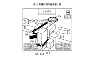
図2は、上記のように構成したナビゲーション装置により立体表示モード時に表示されるナビゲーション画面の例を示す図である。図2において、CMは現在の自車位置を示す車両位置マーク、TMは誘導経路を示す矢印、PMは目的地を示す目的地マーク、TMLは目的地に至る最終経路、BL1,BL2,BL3,・・・・は立体表示された建物である。 FIG. 2 is a diagram showing an example of a navigation screen displayed in the stereoscopic display mode by the navigation device configured as described above. In FIG. 2, CM is a vehicle position mark indicating the current vehicle position, TM is an arrow indicating a guidance route, PM is a destination mark indicating a destination, TML is a final route to the destination, BL1, BL2, BL3,・ ・ ・ ・ Is a three-dimensional building.
図2に示すように、本実施形態では、自車位置CMから見て目的地PMより後方の上空から目的地PMを見下ろした状態で、鳥瞰図による地図を表示するとともに、その鳥瞰図の地図上に複数の建物BL1,BL2,BL3,・・・・を立体表示する。 As shown in FIG. 2, in the present embodiment, a bird's-eye view map is displayed in a state where the destination PM is looked down from above the destination PM as seen from the vehicle position CM, and on the bird's-eye view map. A plurality of buildings BL1, BL2, BL3,.
ここで、目的地PMを後方上空から見下ろす視点は、例えば図3(a)に示すように、自車位置CMから目的地PMへの方向に対してx度(反時計回りを正方向として−90≦x≦90を満たす任意の角度)を成す方向に設定する。図2の例は、x≒45の場合に相当する。 Here, the viewpoint of looking down at the destination PM from the rear sky is, for example, as shown in FIG. 3 (a), x degrees with respect to the direction from the vehicle position CM to the destination PM (counterclockwise is a positive direction − Any angle satisfying 90 ≦ x ≦ 90) is set. The example of FIG. 2 corresponds to the case of x≈45.
また、図3(b)に示すように、目的地PMを後方上空から見下ろす視点を、目的地PMへの最終経路TMLに対してx度(反時計回りを正方向として0≦x≦180を満たす任意の角度)を成す方向に設定するようにしても良い。このような条件の場合、図2の例は、x≒135の場合に相当する。 Further, as shown in FIG. 3B, the viewpoint of looking down at the destination PM from the rear sky is set to x degrees (0 ≦ x ≦ 180 with the counterclockwise direction being the positive direction) with respect to the final route TML to the destination PM. It may be set in a direction that forms an arbitrary angle satisfying. In such a condition, the example of FIG. 2 corresponds to the case of x≈135.
図3(a)の例において、立体画像描画部34は、車両が所定距離あるいは所定時間だけ移動する毎に、移動後の自車位置から目的地への方向に対してx度を成す視点を検出し、その視点から見た立体地図画像を逐次描画する。これにより、ナビゲーション画面上では、車両の移動に伴って、立体地図が少しずつ回転していくように見える。このとき、車両位置マークCMと目的地マークPMとの相対方向は殆ど変わらず、その間の距離のみが車両の移動に伴って近づいていく。 In the example of FIG. 3A, the stereoscopic image drawing unit 34 sets a viewpoint that forms x degrees with respect to the direction from the vehicle position after movement to the destination every time the vehicle moves by a predetermined distance or a predetermined time. The three-dimensional map image detected from the viewpoint is sequentially drawn. Thereby, on the navigation screen, the three-dimensional map appears to rotate little by little as the vehicle moves. At this time, the relative direction between the vehicle position mark CM and the destination mark PM hardly changes, and only the distance between them approaches as the vehicle moves.
一方、図3(b)の例の場合は、目的地を後方上空から見下ろす視点は自車位置と関係がないので、車両の移動にかかわらず、ナビゲーション画面上で立体地図を見ている方向は固定のままである。その代わり、車両の移動に伴って車両位置マークCMが地図上を少しずつ動いていくように見える。 On the other hand, in the example of FIG. 3B, the viewpoint of looking down at the destination from behind is not related to the position of the vehicle, so the direction in which the three-dimensional map is viewed on the navigation screen is regardless of the movement of the vehicle. It remains fixed. Instead, the vehicle position mark CM appears to move little by little on the map as the vehicle moves.
また、図2の例で目的地PMは、ナビゲーション画面の下方部(画面中央より下側、好ましくは画面最下部近傍)に配置する。このようにすれば、目的地PMの後方から見て当該目的地PMの手前に建物の立体表示がされることが少なくなる。さらに、本実施形態では、目的地PMの手間に建物があるかどうかを判別し、ある場合にはその建物を非表示にしている。これにより、目的地PMを画面下方部に配置してもどうしても目的地PMの手前に建物が存在するような場合があっても、目的地PMの手前には常に建物の立体表示がされないようにすることができる。 In the example of FIG. 2, the destination PM is arranged at the lower part of the navigation screen (below the center of the screen, preferably near the bottom of the screen). In this way, the three-dimensional display of the building is reduced before the destination PM as seen from the rear of the destination PM. Furthermore, in this embodiment, it is determined whether or not there is a building between the destination PM, and if there is, the building is not displayed. As a result, even if the destination PM is arranged at the lower part of the screen, even if there is a building in front of the destination PM, the building is not always displayed in front of the destination PM. can do.
このように、自車位置CMの後方上空ではなく、目的地PMの後方上空から見下ろした状態で地図を立体表示することにより、図14に示した従来例のように目的地が手前の建物の陰に隠れて見えなくなる不都合をなくすことができる。これにより、図2のように、自車位置CMから見て目的地PMの手前にある建物BL1に邪魔されることなく、目的地PMの周辺の様子(目的地PMの正確な位置や、その周囲の道路幅あるいは駐車場の有無等)を明瞭に確認することができるようになる。 In this way, by displaying the map in a three-dimensional manner in a state of looking down from behind the destination PM instead of over the rear of the vehicle position CM, the destination of the building in front is like the conventional example shown in FIG. It is possible to eliminate the inconvenience of being hidden behind the screen. As a result, as shown in FIG. 2, the surroundings of the destination PM (the exact position of the destination PM and its position are not disturbed by the building BL1 in front of the destination PM when viewed from the vehicle position CM. The surrounding road width or the presence or absence of a parking lot, etc.) can be clearly confirmed.
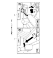
なお、上記の例では、車両位置マークCMは、図2に示す地図エリアの外に自車位置があるときにはナビゲーション画面上に表示されず、当該地図エリアの中に自車位置が入った時点からナビゲーション画面上に表示されることとなる。そこで、図4に示すように、ナビゲーション画面を複数の領域(図4の例では縦方向2つ)に分割し、第1の領域に縮尺の大きな広域地図を表示するとともに、第2の領域(目的地周辺)に縮尺の小さな詳細地図を表示するようにしても良い。 In the above example, the vehicle position mark CM is not displayed on the navigation screen when the vehicle position is outside the map area shown in FIG. 2, but from the time when the vehicle position enters the map area. It will be displayed on the navigation screen. Therefore, as shown in FIG. 4, the navigation screen is divided into a plurality of areas (two in the vertical direction in the example of FIG. 4), a large-scale map with a large scale is displayed in the first area, and the second area ( A detailed map with a small scale may be displayed around the destination).
この図4に示す立体地図は、目的地PMの後方上空から見た立体地図であって、現在位置CMから目的地PMまでの経路が全て画面内に入るように、分割領域毎に表示縮尺を変えて生成したものである。なお、ここでは画面を2つの領域に分割しているが、更に多くの領域に分割して、表示縮尺を段階的に変えて地図表示するようにしても良い。 The three-dimensional map shown in FIG. 4 is a three-dimensional map viewed from behind the destination PM, and the display scale is set for each divided region so that all the routes from the current position CM to the destination PM are within the screen. It is generated by changing. Although the screen is divided into two areas here, it may be divided into more areas and displayed on a map with the display scale changed stepwise.
また、ナビゲーション画面を2画面に分割して、第1の画面に現在地周辺の地図(自車位置を後方から見た状態で表した平面地図もしくは立体地図)を表示するとともに、第2の画面に目的地周辺の立体地図(目的地を後方上空から見下ろした状態で地図および建物を表した立体地図)を表示するようにしても良い。 In addition, the navigation screen is divided into two screens, and a map around the current location (a planar map or a three-dimensional map showing the position of the vehicle viewed from behind) is displayed on the first screen, and the second screen is displayed. A three-dimensional map around the destination (a three-dimensional map representing a map and a building with the destination looked down from above) may be displayed.
図5〜図8は、2画面表示の例を示す図である。このうち図5は、自車位置CMから目的地PMまでが遠距離の場合(例えば、あらかじめ定めた所定距離以上の場合)に表示される画面例を示す。図5において、第1の画面51には自車位置周辺の平面地図が、ユーザにより指定された縮尺に従って表示される。また、第2の画面52には図4と同様の立体地図が表示される。
5 to 8 are diagrams showing examples of two-screen display. Among these, FIG. 5 shows an example of a screen displayed when the distance from the vehicle position CM to the destination PM is a long distance (for example, a predetermined distance or longer). In FIG. 5, the
図6は、自車位置CMから目的地PMまでが近距離の場合(例えば、あらかじめ定めた所定距離以下の場合)に表示される画面例を示す。車両の走行に伴って自車位置CMが目的地PMから所定距離以内に近づくと、図5の画面から図6の画面に自動的に切り替えられ、第2の画面52には目的地周辺の立体地図が図2と同様に詳細に表示される。 FIG. 6 shows an example of a screen that is displayed when the distance from the vehicle position CM to the destination PM is a short distance (for example, a predetermined distance or less). When the vehicle position CM approaches within a predetermined distance from the destination PM as the vehicle travels, the screen of FIG. 5 is automatically switched to the screen of FIG. The map is displayed in detail as in FIG.
図7および図8は、元々設定されている誘導経路からそれて目的地PMまでの経路が大きく変わった場合(誘導経路制御部29のリルート機能により目的地PMまでの誘導経路が再探索された場合)に表示される画面例を示す。 7 and 8 show that when the route from the originally set guide route to the destination PM changes significantly (the guide route to the destination PM is re-searched by the reroute function of the guide route control unit 29). Example of screen displayed in
このうち図7は、図3(a)のように立体表示の視点を設定した場合における表示例を示している。この例によれば、リルートした後も、目的地PMから自車位置CMの見える方向がリルート前と殆ど変わらないように目的地周辺の立体地図が回転する。これに対して図8は、図3(b)のように立体表示の視点を設定した場合における表示例を示している。この例によれば、リルートした後も立体地図は回転せず、自車位置CMから目的地PMに至る誘導経路がTM1からTM2に変化する。 Among these, FIG. 7 shows a display example when a stereoscopic display viewpoint is set as shown in FIG. According to this example, after the reroute, the three-dimensional map around the destination is rotated so that the direction in which the vehicle position CM can be seen from the destination PM is almost the same as that before the reroute. On the other hand, FIG. 8 shows a display example when a stereoscopic display viewpoint is set as shown in FIG. According to this example, the three-dimensional map does not rotate after reroute, and the guidance route from the vehicle position CM to the destination PM changes from TM1 to TM2.
以上詳しく説明したように、本実施形態によれば、自車位置から見て目的地より後方の上空から目的地を見下ろした状態で地図および建物を立体表示するようにしたので、目的地が手前の建物の陰に隠れて見えなくなる不都合をなくすことができる。これによりユーザは、目的地周辺の様子を明瞭に確認することができるようになる。 As described above in detail, according to the present embodiment, the map and the building are displayed in a three-dimensional manner with the destination looking down from the sky above the destination as seen from the position of the host vehicle. You can eliminate the inconvenience of hiding behind the building. As a result, the user can clearly check the situation around the destination.
なお、上記実施形態では、目的地を後方上空から見下ろす視点の条件として、図3(a)(b)の例を挙げて説明した。これらは両方とも角度xの値が固定であるが、これを可変の値としても良い。例えば、立体画像位置検出部35により検出される建物の位置情報と、誘導経路メモリ30から読み出される目的地の位置情報とに基づいて、目的地の後方上空から見て当該目的地の手前に建物がない角度xを探し出し、その角度xを成す後方上空から見下ろした状態で立体画像を描画するようにしても良い。このような角度が1つも存在しない場合には、図3(a)あるいは図3(b)のような固定の角度xを採用し、目的地の手前にある建物を非表示とすれば良い。
In the above-described embodiment, the example of FIGS. 3A and 3B has been described as the condition for the viewpoint of looking down at the destination from behind. In both cases, the value of the angle x is fixed, but this may be a variable value. For example, based on the position information of the building detected by the three-dimensional image
また、上記実施形態では、目的地の手前に建物が存在する場合にはその建物を非表示にする例について説明したが、これに限定されるものではない。例えば、当該手前の建物を半透化(建物をフレームのみで表し、その後ろにある道路や建物も見えるように表示)するようにしても良い。 Moreover, although the said embodiment demonstrated the example which hides the building when the building exists before the destination, it is not limited to this. For example, the building in front may be semi-transparent (displayed so that the building is represented by a frame and the roads and buildings behind it are visible).
また、目的地の手前にある建物を普通に表示するとともに、当該目的地の手前にある建物の高さ情報と、当該建物と目的地との相対位置関係情報(例えば、建物と目的地との間にある道路の幅情報など)に基づいて、目的地の手前にある建物の更に上方から目的地が見えるように視点の高さを変えて地図表示するようにしても良い。 In addition, the building in front of the destination is normally displayed, the height information of the building in front of the destination, and the relative positional relationship information between the building and the destination (for example, the building and the destination Based on the width information of the road in between, the map may be displayed with the height of the viewpoint changed so that the destination can be seen from above the building in front of the destination.
図9は、この場合のナビゲーション装置の構成例を示すブロック図である。なお、図9において、図1に示した符号と同一の符号を付したものは同一の機能を有するものであるので、ここでは重複する説明を省略する。図9に示す例では、図1に示した立体画像描画部34の代わりに、これと異なる機能を有する立体画像描画部45を備えている。また、テーブル情報記憶部46を更に備えている。
FIG. 9 is a block diagram showing a configuration example of the navigation device in this case. In FIG. 9, components having the same reference numerals as those shown in FIG. 1 have the same functions, and thus redundant description is omitted here. In the example shown in FIG. 9, a stereoscopic
テーブル情報記憶部46は、目的地とその手前の建物との間がどれだけ離れていて、その建物の高さがどれくらいのときに、どの程度まで視点を高くすれば目的地が見えるかを表したテーブル情報をあらかじめ記憶している。立体画像描画部45は、目的地の手前にある建物の高さ情報(立体画像バッファ22に格納される建物データ中に含まれる)と、当該建物と目的地との間にある道路幅情報(地図バッファ21に格納される地図データ中に含まれる)とに基づいて上述のテーブル情報を参照し、目的地が見える視点の高さを求める。そして、その求めた視点の高さから目的地を見下ろした状態の立体画像を描画する。
The table information storage unit 46 indicates how far the destination is from the building in front of it, how high the building is, and how high the viewpoint is to see the destination. The table information is stored in advance. The three-dimensional
なお、目的地の手前にある建物の高さ情報と、目的地とその手前の建物との間にある道路の幅情報とが、テーブル情報に記憶されている何れの条件にも合致しない場合は、どんなに視点を高くしても目的地を見ることができないと判断する。この場合は、立体画像描画部45は規定の高さから立体画像を描画し、立体画像調整部36が当該手間の建物を非表示とするべく、該当する建物の画像データを消去する。
If the height information of the building in front of the destination and the width information of the road between the destination and the building in front of the destination do not match any of the conditions stored in the table information Judge that you cannot see your destination no matter how high your viewpoint. In this case, the three-dimensional
(第2の実施形態)
次に、本発明の第2の実施形態について説明する。図10は、第2の実施形態によるナビゲーション装置の構成例を示すブロック図である。なお、図10において、図1に示した符号と同一の符号を付したものは同一の機能を有するものであるので、ここでは重複する説明を省略する。
(Second Embodiment)
Next, a second embodiment of the present invention will be described. FIG. 10 is a block diagram illustrating a configuration example of the navigation device according to the second embodiment. In FIG. 10, components having the same reference numerals as those shown in FIG. 1 have the same functions, and thus redundant description is omitted here.
図10に示す第2の実施形態では、図1に示したROM読出制御部23、立体画像描画部34の代わりに、これと異なる機能を有するROM読出制御部51、立体画像描画部52を備えている。
The second embodiment shown in FIG. 10 includes a ROM read
ROM読出制御部51は、誘導経路制御部29から入力される目的地と自車位置との距離情報(マップマッチング制御部28から入力される車両現在位置情報と、誘導経路メモリ30に設定された目的地の位置情報とから求められる)に基づいて、目的地と自車位置との双方が一画面内に同時に入るスケールの地図データおよび建物データをDVD−ROM11から読み出す。このときROM読出制御部51は、目的地が画面下方部、車両現在位置が画面上方部に位置するような最適なスケールを選択する。
The ROM read
DVD−ROM11に記録された地図データは、広い地域を一望するための上位レベル(広域スケール)の地図から、狭い地域を詳細に記述した下位レベル(狭域スケール)の地図まで、レベルと呼ばれる単位に階層化して管理されている。各レベルは、所定の経度および緯度で区切られた区画と呼ばれる矩形領域を単位として分割されている。各区画の地図データは、ROM読出制御部51が区画番号を指定することによって読み出すことが可能となっている。
The map data recorded on the DVD-
立体画像描画部52は、地図バッファ21に格納された地図データと立体画像バッファ22に格納された建物データとに基づいて、目的地と自車位置とが一画面内に同時に入るスケールで鳥瞰図による地図および当該鳥瞰図上の建物の立体表示に必要な立体画像データを生成する。このとき立体画像描画部52は、車両の走行に伴って逐次変化する目的地と自車位置との距離に応じて、鳥瞰図表示する際の視点の高さを徐々に変更しながら立体画像データを逐次再描画する。
Based on the map data stored in the
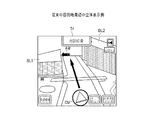
次に、上記のように構成した第2の実施形態によるナビゲーション装置の動作を説明する。図11は、第2の実施形態による地図スケールの切り替えおよび視点高さの変更に関する動作例を示す図である。また、図12は、地図スケールの切り替えによる画面表示例を示す図である。 Next, the operation of the navigation device according to the second embodiment configured as described above will be described. FIG. 11 is a diagram illustrating an operation example related to map scale switching and viewpoint height change according to the second embodiment. FIG. 12 is a diagram illustrating a screen display example by switching the map scale.
図11に示すように、本実施形態においても第1の実施形態と同様に、目的地PMを起点としてその上空に設定した視点から目的地PMおよび自車位置CM1〜CM3を投影する状態で、鳥瞰図による地図を表示するとともに、その鳥瞰図の地図上に複数の建物を立体表示する。 As shown in FIG. 11, in the present embodiment as well as in the first embodiment, the destination PM and the vehicle positions CM1 to CM3 are projected from the viewpoint set above the destination PM as a starting point. A map based on a bird's eye view is displayed, and a plurality of buildings are three-dimensionally displayed on the bird's eye view map.
このとき、目的地PMが画面下方部、自車位置CM1〜CM3が画面上方部に位置するような最適なスケールに適宜切り替えながら地図を表示する。すなわち、図11の例において、DVD−ROM11内の地図データとして、20[km]スケールの地図データMP1、1[km]スケールの地図データMP2、10[m]スケールの地図データMP3が用意されていたとする。
At this time, the map is displayed while appropriately switching to an optimal scale such that the destination PM is located at the lower part of the screen and the vehicle positions CM1 to CM3 are located at the upper part of the screen. That is, in the example of FIG. 11, map data MP1 of 20 [km] scale, map data MP2 of 1 [km] scale, map data MP3 of 10 [m] scale are prepared as map data in the DVD-
この場合に、目的地PMとの距離Dが20[km]≧D>1[km]の範囲内に自車位置CM1があるときには20[km]スケールの地図MP1を表示し、目的地PMとの距離Dが1[km]≧D>10[m]の範囲内に自車位置CM2があるときには1[km]スケールの地図MP2を表示し、目的地PMとの距離Dが10[m]≧Dの範囲内に自車位置CM3があるときには10[m]スケールの地図MP3を表示する。 In this case, when the vehicle position CM1 is within the range D of 20 [km] ≧ D> 1 [km] with respect to the destination PM, a map MP1 of 20 [km] scale is displayed, and the destination PM and When the vehicle distance CM2 is within the range of 1 [km] ≧ D> 10 [m], the map MP2 of 1 [km] scale is displayed and the distance D to the destination PM is 10 [m]. When the vehicle position CM3 is within the range of ≧ D, the map MP3 of 10 [m] scale is displayed.
すなわち、例えば20[km]スケールの地図MP1上で自車位置CM1が目的地PMに向かって移動していき、目的地PMと自車位置CM1との間の距離が次の1[km]スケールの値まで小さくなったときに、20[km]スケールの地図MP1から次の1[km]スケールの地図MP2へと切り替えを行って表示する。1[km]スケールの地図MP2から10[m]スケールの地図MP3への切り替えも同様にして行う。 That is, for example, the host vehicle position CM1 moves toward the destination PM on the map MP1 of 20 [km] scale, and the distance between the destination PM and the host vehicle position CM1 is the next 1 [km] scale. When the value becomes smaller, the map MP1 on the 20 [km] scale is switched to the next map MP2 on the 1 [km] scale and displayed. Switching from the 1 [km] scale map MP2 to the 10 [m] scale map MP3 is performed in the same manner.
このように、目的地PMと自車位置CM1〜CM3との距離に応じて地図スケールを適宜切り替えながら表示することにより、図12に示すように、自車位置が目的地にどの程度近づいても、目的地PMを画面下方部(好ましくは、画面最下部の中央付近)に固定して表示するとともに、自車位置CM1〜CM3を画面上方部(好ましくは、画面最上部の中央付近)に表示することができる。 In this way, by displaying the map scale while appropriately switching the map according to the distance between the destination PM and the vehicle positions CM1 to CM3, as shown in FIG. 12, how close the vehicle position is to the destination. The destination PM is fixedly displayed at the lower part of the screen (preferably near the center at the bottom of the screen), and the vehicle positions CM1 to CM3 are displayed at the upper part of the screen (preferably near the center at the top of the screen). can do.
さらに、本実施形態では、逐次変化する目的地PMと自車位置CM1〜CM3との距離に応じて、視点の高さを徐々に変更しながら地図を表示している。すなわち、図11の例において、20[km]スケールの地図MP1に切り替えた直後では、視点VW1の位置から投影した立体地図データを描画する。その後、自車位置CM1が所定距離あるいは所定角度だけ進む毎に、視点VW1の高さを徐々に下げながら立体地図データを逐次描画していく。 Further, in the present embodiment, the map is displayed while gradually changing the height of the viewpoint according to the distance between the destination PM and the vehicle positions CM1 to CM3 that change sequentially. That is, in the example of FIG. 11, immediately after switching to the map [MP1] of 20 [km] scale, the 3D map data projected from the position of the viewpoint VW1 is drawn. Thereafter, each time the host vehicle position CM1 advances by a predetermined distance or a predetermined angle, the three-dimensional map data is sequentially drawn while gradually decreasing the height of the viewpoint VW1.
そして、20[km]スケールの地図MP1から1[km]スケールの地図MP2に切り替えられた直後では、視点VW2の位置から投影した立体地図データを描画する。同様にして、その後自車位置CM2が所定距離あるいは所定角度だけ進む毎に、視点VW2の高さを徐々に下げながら立体地図データを再描画していく。そして、10[m]スケールの地図MP3に切り替えられた直後には、視点VW3の位置から投影した立体地図データを描画する。 Immediately after switching from the map MP1 of 20 [km] scale to the map MP2 of 1 [km] scale, the stereoscopic map data projected from the position of the viewpoint VW2 is drawn. Similarly, each time the host vehicle position CM2 advances by a predetermined distance or a predetermined angle, the three-dimensional map data is redrawn while gradually decreasing the height of the viewpoint VW2. Immediately after switching to the 10 [m] scale map MP3, the 3D map data projected from the position of the viewpoint VW3 is drawn.
最小スケール(10[m]スケール)の地図MP3に切り替えた後は、車両の走行に伴い自車位置CM3が目的地PMに向かって徐々に移動していくように描画する。その間も視点VW3の高さを徐々に下げて、実際の目的地PMの高さに近づけていく。そして、最終的に目的地PMに到着した時点で、当該目的地PMの高さから見た状態の立体地図データを描画するようにする。 After the map MP3 is switched to the minimum scale (10 [m] scale), the vehicle position CM3 is drawn so as to gradually move toward the destination PM as the vehicle travels. In the meantime, the height of the viewpoint VW3 is gradually lowered to approach the height of the actual destination PM. Then, when the final destination PM is finally reached, the 3D map data viewed from the height of the destination PM is drawn.
図13は、目的地周辺における地図画像の画面表示例を示す図である。目的地PMがビルの中の上位階にある場合には、図13(a)のように、目的地PMの上位階から自車を覗き込むような視点で地図が表示される。一方、目的地PMが地上にある場合には、図13(b)のように、地上の目線位置から自車を見るような視点で地図が表示される。 FIG. 13 is a diagram illustrating a screen display example of a map image around the destination. When the destination PM is on the upper floor in the building, as shown in FIG. 13A, the map is displayed from the viewpoint of looking into the vehicle from the upper floor of the destination PM. On the other hand, when the destination PM is on the ground, as shown in FIG. 13B, the map is displayed from the viewpoint of looking at the vehicle from the position of the eyes on the ground.
このように、目的地PMと自車位置CM1〜CM3との距離に応じて単に地図スケールを切り替えるだけでなく、視点VW1〜VW3の高さを徐々に低く変更していくようにして地図を逐次再描画することにより、自車位置CM1〜CM3を画面上方部(画面最上部の中央付近)にほぼ固定して表示することができる。 In this way, not only the map scale is simply switched according to the distance between the destination PM and the vehicle positions CM1 to CM3, but the map is sequentially changed so that the heights of the viewpoints VW1 to VW3 are gradually lowered. By redrawing, the own vehicle positions CM1 to CM3 can be displayed almost fixed at the upper part of the screen (near the center of the uppermost part of the screen).
すなわち、単に地図スケールを切り替えるだけでは、切り替えが行われる間の同じスケールの地図を使用中は、自車位置CM1〜CM3が画面上方部で目的地PMに向かって多少移動する。これに対して、視点VW1〜VW3の高さを徐々に低くすることにより、より低い位置から鳥瞰した場合に得られる距離の圧縮効果によって、同じスケールの地図を使用中でも自車位置CM1〜CM3が画面上方部で殆ど動かないように見せることが可能となる。 That is, by simply switching the map scale, the vehicle positions CM1 to CM3 move slightly toward the destination PM in the upper part of the screen while using the map of the same scale during the switching. On the other hand, by gradually reducing the height of the viewpoints VW1 to VW3, the vehicle positions CM1 to CM3 can be used even when the same scale map is being used due to the compression effect of the distance obtained when bird's-eye view from a lower position. It is possible to make it appear to move little at the upper part of the screen.
目的地PMを画面下方部、自車位置CM1〜CM3を画面上方部にほぼ固定して表示できることにより、目的地PMと自車位置CM1〜CM3との位置関係を分かりやすい形でユーザに提供することができる。また、画面内で自車位置CM1〜CM3から目的地PMまでの距離をできるだけ大きくとることができ、その間の誘導経路を画面全体にわたってフルに表示することができる。 Since the destination PM can be displayed at a lower part of the screen and the vehicle positions CM1 to CM3 are substantially fixed to the upper part of the screen, the positional relationship between the destination PM and the vehicle positions CM1 to CM3 is provided to the user in an easily understandable form be able to. Further, the distance from the vehicle positions CM1 to CM3 to the destination PM can be as large as possible in the screen, and the guidance route between them can be displayed fully over the entire screen.
以上詳しく説明したように、第2の実施形態によれば、第1の実施形態と同様に自車位置から見て目的地より後方の上空から目的地を見下ろした状態で地図および建物を立体表示するようにしたので、目的地が手前の建物の陰に隠れて見えなくなる不都合をなくすことができる。これによりユーザは、目的地周辺の様子を明瞭に確認することができるようになる。 As described above in detail, according to the second embodiment, as in the first embodiment, the map and the building are displayed in a three-dimensional manner with the destination looking down from the sky above the destination as seen from the vehicle position. As a result, it is possible to eliminate the inconvenience that the destination is hidden behind the building in front. As a result, the user can clearly check the situation around the destination.
また、上記第2の実施形態では、目的地と自車位置とを一画面内に同時に表示可能となるように地図スケールを適宜切り替えながら地図を表示するようにしたので、ユーザは目的地周辺の様子だけでなく、目的地と現在地との位置関係も直感的に理解することができる。また、目的地と自車位置との距離に応じて視点の高さを徐々に変更するようにしたので、画面を有効利用して、現在地から目的地までの情報を画面上にフルに表示することができる。 In the second embodiment, since the map is displayed while appropriately switching the map scale so that the destination and the vehicle position can be simultaneously displayed on one screen, the user can display the map around the destination. You can intuitively understand not only the situation but also the positional relationship between the destination and the current location. In addition, since the height of the viewpoint is gradually changed according to the distance between the destination and the vehicle position, the information from the current location to the destination is fully displayed on the screen using the screen effectively. be able to.
なお、上記第2の実施形態では、自車位置CM1〜CM3と目的地PMとが一画面内に入る地図スケールを選択する例について説明したが、これに限定されない。例えば、誘導経路が大きく屈曲している場合、比較的遠方に経由地が設定されているような場合などには、自車位置CM1〜CM3と目的地PMとが一画面内に入っていても、その間における誘導経路の一部が一画面内に入りきらないケースもある。このような場合に対応するために、自車位置CM1〜CM3と目的地PM、更にその間における誘導経路の全てが一画面内に入るような地図スケールを適宜選択するようにしても良い。 In the second embodiment, the example in which the vehicle scales CM1 to CM3 and the destination PM select a map scale that falls within one screen has been described. However, the present invention is not limited to this. For example, when the guidance route is bent significantly, or when a stopover is set relatively far away, the vehicle positions CM1 to CM3 and the destination PM may be within one screen. In some cases, a part of the guide route in the meantime does not fit within one screen. In order to cope with such a case, a map scale may be selected as appropriate so that the own vehicle positions CM1 to CM3 and the destination PM, and further, all the guidance routes between them are within one screen.
また、上記実施形態では、あらかじめ用意された離散的なスケールの地図を単に切り替えて表示する例について説明したが、これに限定されない。例えば、車両が所定距離あるいは所定角度だけ移動する毎に、そのときの自車位置CM1〜CM3と目的地PMとの距離に応じたスケールの地図を補間演算によって生成して、逐次再描画するようにしても良い。 Moreover, although the said embodiment demonstrated the example which switches and displays the map of the discrete scale prepared beforehand, it was not limited to this. For example, every time the vehicle moves by a predetermined distance or a predetermined angle, a map of a scale corresponding to the distance between the vehicle positions CM1 to CM3 and the destination PM at that time is generated by interpolation calculation and redrawn sequentially. Anyway.
例えば、目的地PMとの距離Dが20[km]≧D>1[km]の範囲内に自車位置CM1があるときに、当該自車位置CM1の位置に応じて、20[km]スケールの地図と1[km]スケールの地図とを用いて補間演算を行うことにより、そのときの距離Dに応じたスケールの地図を逐次生成して再描画するようにする。このようにした場合も、自車位置CM1〜CM3が画面上方部で殆ど動かないように見せることができる。 For example, when the host vehicle position CM1 is within the range of 20 [km] ≧ D> 1 [km], the distance D to the destination PM is 20 [km] scale according to the position of the host vehicle position CM1. And a 1 [km] scale map are interpolated to sequentially generate and redraw a scale map corresponding to the distance D at that time. Even in this case, it can be seen that the vehicle positions CM1 to CM3 hardly move in the upper part of the screen.
以上に説明した第1および第2の実施形態による立体表示の手法は、ハードウェア構成、DSP、ソフトウェアの何れによっても実現することが可能である。例えばソフトウェアによって実現する場合、各実施形態のナビゲーション制御装置100は、実際にはコンピュータのCPUあるいはMPU、RAM、ROMなどを備えて構成され、RAMやROMに記憶されたプログラムが動作することによって実現できる。
The stereoscopic display methods according to the first and second embodiments described above can be realized by any of a hardware configuration, a DSP, and software. For example, when realized by software, the
したがって、コンピュータが各実施形態の機能を果たすように動作させるプログラムを例えばCD−ROMのような記録媒体に記録し、コンピュータに読み込ませることによって実現できるものである。上記プログラムを記録する記録媒体としては、CD−ROM以外に、フレキシブルディスク、ハードディスク、磁気テープ、光ディスク、光磁気ディスク、DVD、不揮発性メモリカード等を用いることができる。 Therefore, it can be realized by recording a program that causes a computer to perform the functions of each embodiment on a recording medium such as a CD-ROM and causing the computer to read the program. As a recording medium for recording the program, a flexible disk, a hard disk, a magnetic tape, an optical disk, a magneto-optical disk, a DVD, a nonvolatile memory card, and the like can be used in addition to the CD-ROM.
また、最近のナビゲーション装置は通信機能を備えるものや、通信機能を備えた携帯電話等に接続して使用できるものが存在する。この種のナビゲーション装置の場合は、上記プログラムをインターネット等のネットワークを介してコンピュータにダウンロードすることによっても上述した各実施形態の機能を実現することができる。 Some recent navigation devices have a communication function, and others can be used by connecting to a mobile phone having the communication function. In the case of this type of navigation device, the functions of the above-described embodiments can also be realized by downloading the program to a computer via a network such as the Internet.
また、各実施形態によるナビゲーション制御装置100の機能をネットワーク環境で実現するべく、全部あるいは一部のプログラムが他のコンピュータで実行されるようになっていても良い。
Further, in order to realize the functions of the
また、コンピュータが供給されたプログラムを実行することにより各実施形態の機能が実現されるだけでなく、そのプログラムがコンピュータにおいて稼働しているOS(オペレーティングシステム)あるいは他のアプリケーションソフト等と共同して各実施形態の機能が実現される場合や、供給されたプログラムの処理の全てあるいは一部がコンピュータの機能拡張ボードや機能拡張ユニットにより行われて各実施形態の機能が実現される場合も、かかるプログラムは本発明の実施形態に含まれる。 In addition, the functions of the respective embodiments are realized by executing a program supplied by a computer, and the program is jointly operated with an OS (operating system) or other application software running on the computer. This is also the case when the functions of the embodiments are realized, or when all or part of the processing of the supplied program is performed by a function expansion board or function expansion unit of the computer to realize the functions of the embodiments. The program is included in an embodiment of the present invention.
その他、上記第1および第2の実施形態は、何れも本発明を実施するにあたっての具体化の一例を示したものに過ぎず、これによって本発明の技術的範囲が限定的に解釈されてはならないものである。すなわち、本発明はその精神、またはその主要な特徴から逸脱することなく、様々な形で実施することができる。 In addition, each of the first and second embodiments described above is merely an example of implementation in carrying out the present invention, and the technical scope of the present invention should not be interpreted in a limited manner. It will not be. In other words, the present invention can be implemented in various forms without departing from the spirit or main features thereof.
本発明は、地図上に建物を立体表示する機能を備えたナビゲーション装置において、目的地の正確な位置や周囲の状況、目的地と現在地との位置関係等を分かりやすく立体表示できるようにするのに有用である。 The present invention provides a navigation device having a function of stereoscopically displaying a building on a map so that the accurate position of the destination, the surrounding situation, the positional relationship between the destination and the current location, and the like can be easily displayed in a stereoscopic manner. Useful for.
21 地図バッファ
22 立体画像バッファ
31 地図描画部
32 VRAM
33 読出制御部
34 立体画像描画部
35 立体画像位置検出部
36 立体画像調整部
45 立体画像描画部
46 テーブル情報記憶部
51 ROM読出制御部
52 立体画像描画部
21
33 Reading Control Unit 34 Stereo
Claims (17)
自車位置から見て目的地より後方上空から上記目的地を見下ろした状態で地図を鳥瞰図表示するとともに、当該鳥瞰図の地図上に建物を立体表示するようにしたことを特徴とするナビゲーション用立体表示方法。 In the three-dimensional display method for navigation which displays a building three-dimensionally on a map,
A three-dimensional navigation display characterized by displaying a bird's-eye view of the map with the above-mentioned destination looking down from above the destination as seen from the position of the vehicle and displaying the building in a three-dimensional manner on the map of the bird's-eye view Method.
上記目的地基準画像描画手段により描画された目的地基準の立体画像を表示装置に表示するように制御する表示制御手段とを備えたことを特徴とするナビゲーション装置。 Draw a map with a bird's-eye view in a state of looking down on the destination from the sky above the destination as seen from the vehicle position, and a destination reference image drawing means for drawing a building three-dimensionally on the map of the bird's-eye view,
A navigation apparatus comprising: display control means for controlling to display a destination-based stereoscopic image drawn by the destination-reference image drawing means on a display device.
上記表示制御手段は、上記表示装置の画面を複数に分割し、第1の画面に対して上記現在地基準画像描画手段により描画された現在地基準の画像を表示するとともに、第2の画面に対して上記目的地基準画像描画手段により描画された目的地基準の立体画像を表示するように制御することを特徴とする請求項11に記載のナビゲーション装置。 A current location reference image drawing means for drawing a map in a state where the vehicle position is viewed from behind,
The display control means divides the screen of the display device into a plurality of parts, displays the current location reference image drawn by the current location reference image drawing means on the first screen, and displays the second screen on the second screen. 12. The navigation apparatus according to claim 11, wherein control is performed so as to display a destination-based stereoscopic image drawn by the destination-reference image drawing means.
Priority Applications (1)
| Application Number | Priority Date | Filing Date | Title |
|---|---|---|---|
| JP2003304053A JP4105609B2 (en) | 2003-01-06 | 2003-08-28 | 3D display method for navigation and navigation apparatus |
Applications Claiming Priority (2)
| Application Number | Priority Date | Filing Date | Title |
|---|---|---|---|
| JP2003000621 | 2003-01-06 | ||
| JP2003304053A JP4105609B2 (en) | 2003-01-06 | 2003-08-28 | 3D display method for navigation and navigation apparatus |
Publications (2)
| Publication Number | Publication Date |
|---|---|
| JP2004233333A JP2004233333A (en) | 2004-08-19 |
| JP4105609B2 true JP4105609B2 (en) | 2008-06-25 |
Family
ID=32964568
Family Applications (1)
| Application Number | Title | Priority Date | Filing Date |
|---|---|---|---|
| JP2003304053A Expired - Lifetime JP4105609B2 (en) | 2003-01-06 | 2003-08-28 | 3D display method for navigation and navigation apparatus |
Country Status (1)
| Country | Link |
|---|---|
| JP (1) | JP4105609B2 (en) |
Cited By (1)
| Publication number | Priority date | Publication date | Assignee | Title |
|---|---|---|---|---|
| CN104075719A (en) * | 2013-03-26 | 2014-10-01 | 高德信息技术有限公司 | Three-dimensional navigation method and three-dimensional navigation device |
Families Citing this family (14)
| Publication number | Priority date | Publication date | Assignee | Title |
|---|---|---|---|---|
| JP4710464B2 (en) * | 2005-07-22 | 2011-06-29 | 株式会社デンソー | Car navigation system |
| JP2007286158A (en) * | 2006-04-13 | 2007-11-01 | Xanavi Informatics Corp | Navigation apparatus |
| JP5159070B2 (en) * | 2006-08-31 | 2013-03-06 | アルパイン株式会社 | Vehicle periphery image display device and display method |
| JP2008286653A (en) * | 2007-05-18 | 2008-11-27 | Sanyo Electric Co Ltd | Navigation device |
| JP5243107B2 (en) * | 2008-05-27 | 2013-07-24 | クラリオン株式会社 | Navigation device and screen display control method |
| JP5402322B2 (en) | 2009-07-02 | 2014-01-29 | ソニー株式会社 | Information processing apparatus and information processing method |
| JP5792424B2 (en) | 2009-07-03 | 2015-10-14 | ソニー株式会社 | MAP INFORMATION DISPLAY DEVICE, MAP INFORMATION DISPLAY METHOD, AND PROGRAM |
| EP2453208A1 (en) * | 2010-11-15 | 2012-05-16 | Harman Becker Automotive Systems GmbH | Navigation system |
| JP5323171B2 (en) * | 2011-12-08 | 2013-10-23 | 三洋電機株式会社 | Navigation device |
| US20140298224A1 (en) * | 2012-01-12 | 2014-10-02 | Mitsubishi Electric Corporation | Map display device and map display method |
| JP6962397B2 (en) * | 2016-03-15 | 2021-11-05 | 株式会社デンソー | Display control device and display control method |
| JP7119798B2 (en) * | 2018-09-07 | 2022-08-17 | 株式会社アイシン | display controller |
| CN111238506B (en) * | 2018-11-29 | 2022-10-18 | 沈阳美行科技股份有限公司 | Drawing method and device for elevated road in map and related equipment |
| JP7319635B2 (en) * | 2021-11-02 | 2023-08-02 | グリー株式会社 | Computer program, virtual space display device, and virtual space display method |
-
2003
- 2003-08-28 JP JP2003304053A patent/JP4105609B2/en not_active Expired - Lifetime
Cited By (1)
| Publication number | Priority date | Publication date | Assignee | Title |
|---|---|---|---|---|
| CN104075719A (en) * | 2013-03-26 | 2014-10-01 | 高德信息技术有限公司 | Three-dimensional navigation method and three-dimensional navigation device |
Also Published As
| Publication number | Publication date |
|---|---|
| JP2004233333A (en) | 2004-08-19 |
Similar Documents
| Publication | Publication Date | Title |
|---|---|---|
| JP6606494B2 (en) | Apparatus and method for displaying navigation instructions | |
| JP4715353B2 (en) | Image processing apparatus, drawing method, and drawing program | |
| US6360168B1 (en) | Navigation apparatus | |
| JP4105609B2 (en) | 3D display method for navigation and navigation apparatus | |
| JP4809900B2 (en) | Navigation device, map display method, and map display program | |
| JP4743400B2 (en) | Automotive electronic devices | |
| JP2009020089A (en) | System, method, and program for navigation | |
| US20110288763A1 (en) | Method and apparatus for displaying three-dimensional route guidance | |
| JP2009505098A (en) | Navigation device and method for scrolling map data displayed on navigation device | |
| JP2004212255A (en) | Navigation device | |
| JPWO2007142084A1 (en) | Navigation device | |
| JP2007040761A (en) | Navigation system, terminal, and map display method | |
| WO2009118911A1 (en) | Map display, navigation device, generating method, map image generating program, and computer-readable recording medium | |
| JP4099401B2 (en) | Navigation device | |
| JP2013029341A (en) | Navigation device and narrow street search method | |
| JP5060856B2 (en) | Navigation system and navigation method | |
| JP4293893B2 (en) | Navigation device and landmark display method | |
| JP2022058570A (en) | Image control program, image control device, and image control method | |
| JP4906272B2 (en) | Map display system, information distribution server, map display device, and program | |
| JP2008249655A (en) | Navigation device, method, program, and recording medium | |
| JP2004085611A (en) | Device of controlling map scroll and navigation system using same | |
| JP2000321975A (en) | Map displaying device | |
| JPH1183503A (en) | Navigator | |
| JP4109130B2 (en) | 3D display method for navigation and navigation apparatus | |
| JP4644451B2 (en) | Navigation device and mountain range display method |
Legal Events
| Date | Code | Title | Description |
|---|---|---|---|
| A621 | Written request for application examination |
Free format text: JAPANESE INTERMEDIATE CODE: A621 Effective date: 20051130 |
|
| A977 | Report on retrieval |
Free format text: JAPANESE INTERMEDIATE CODE: A971007 Effective date: 20071213 |
|
| A131 | Notification of reasons for refusal |
Free format text: JAPANESE INTERMEDIATE CODE: A131 Effective date: 20071225 |
|
| A521 | Written amendment |
Free format text: JAPANESE INTERMEDIATE CODE: A523 Effective date: 20080219 |
|
| TRDD | Decision of grant or rejection written | ||
| A01 | Written decision to grant a patent or to grant a registration (utility model) |
Free format text: JAPANESE INTERMEDIATE CODE: A01 Effective date: 20080325 |
|
| A61 | First payment of annual fees (during grant procedure) |
Free format text: JAPANESE INTERMEDIATE CODE: A61 Effective date: 20080327 |
|
| R150 | Certificate of patent or registration of utility model |
Free format text: JAPANESE INTERMEDIATE CODE: R150 |
|
| FPAY | Renewal fee payment (event date is renewal date of database) |
Free format text: PAYMENT UNTIL: 20110404 Year of fee payment: 3 |
|
| FPAY | Renewal fee payment (event date is renewal date of database) |
Free format text: PAYMENT UNTIL: 20120404 Year of fee payment: 4 |
|
| FPAY | Renewal fee payment (event date is renewal date of database) |
Free format text: PAYMENT UNTIL: 20120404 Year of fee payment: 4 |
|
| FPAY | Renewal fee payment (event date is renewal date of database) |
Free format text: PAYMENT UNTIL: 20130404 Year of fee payment: 5 |
|
| FPAY | Renewal fee payment (event date is renewal date of database) |
Free format text: PAYMENT UNTIL: 20130404 Year of fee payment: 5 |
|
| FPAY | Renewal fee payment (event date is renewal date of database) |
Free format text: PAYMENT UNTIL: 20140404 Year of fee payment: 6 |