JP4100570B2 - Vehicle locking device - Google Patents
Vehicle locking device Download PDFInfo
- Publication number
- JP4100570B2 JP4100570B2 JP2003346194A JP2003346194A JP4100570B2 JP 4100570 B2 JP4100570 B2 JP 4100570B2 JP 2003346194 A JP2003346194 A JP 2003346194A JP 2003346194 A JP2003346194 A JP 2003346194A JP 4100570 B2 JP4100570 B2 JP 4100570B2
- Authority
- JP
- Japan
- Prior art keywords
- vehicle
- knob
- locking device
- operation knob
- rotation shaft
- Prior art date
- Legal status (The legal status is an assumption and is not a legal conclusion. Google has not performed a legal analysis and makes no representation as to the accuracy of the status listed.)
- Expired - Lifetime
Links
- 210000000078 claw Anatomy 0.000 claims description 20
- 230000007246 mechanism Effects 0.000 claims description 15
- 230000005540 biological transmission Effects 0.000 claims description 7
- 230000004044 response Effects 0.000 claims description 3
- 230000002093 peripheral effect Effects 0.000 claims description 2
- 238000000034 method Methods 0.000 description 9
- 230000008569 process Effects 0.000 description 9
- 238000010586 diagram Methods 0.000 description 5
- 238000004891 communication Methods 0.000 description 3
- 239000000446 fuel Substances 0.000 description 2
- 238000002347 injection Methods 0.000 description 2
- 239000007924 injection Substances 0.000 description 2
- WHXSMMKQMYFTQS-UHFFFAOYSA-N Lithium Chemical compound [Li] WHXSMMKQMYFTQS-UHFFFAOYSA-N 0.000 description 1
- 230000004913 activation Effects 0.000 description 1
- 238000013459 approach Methods 0.000 description 1
- 238000010276 construction Methods 0.000 description 1
- 230000001276 controlling effect Effects 0.000 description 1
- 238000006073 displacement reaction Methods 0.000 description 1
- 239000002828 fuel tank Substances 0.000 description 1
- 229910052744 lithium Inorganic materials 0.000 description 1
- 238000012423 maintenance Methods 0.000 description 1
- 230000007257 malfunction Effects 0.000 description 1
- 238000012545 processing Methods 0.000 description 1
- 230000001105 regulatory effect Effects 0.000 description 1
- 239000007858 starting material Substances 0.000 description 1
Images


Classifications
-
- B—PERFORMING OPERATIONS; TRANSPORTING
- B60—VEHICLES IN GENERAL
- B60R—VEHICLES, VEHICLE FITTINGS, OR VEHICLE PARTS, NOT OTHERWISE PROVIDED FOR
- B60R25/00—Fittings or systems for preventing or indicating unauthorised use or theft of vehicles
- B60R25/20—Means to switch the anti-theft system on or off
- B60R25/2063—Ignition switch geometry
-
- E—FIXED CONSTRUCTIONS
- E05—LOCKS; KEYS; WINDOW OR DOOR FITTINGS; SAFES
- E05B—LOCKS; ACCESSORIES THEREFOR; HANDCUFFS
- E05B49/00—Electric permutation locks; Circuits therefor ; Mechanical aspects of electronic locks; Mechanical keys therefor
-
- B—PERFORMING OPERATIONS; TRANSPORTING
- B60—VEHICLES IN GENERAL
- B60R—VEHICLES, VEHICLE FITTINGS, OR VEHICLE PARTS, NOT OTHERWISE PROVIDED FOR
- B60R25/00—Fittings or systems for preventing or indicating unauthorised use or theft of vehicles
- B60R25/01—Fittings or systems for preventing or indicating unauthorised use or theft of vehicles operating on vehicle systems or fittings, e.g. on doors, seats or windscreens
- B60R25/02—Fittings or systems for preventing or indicating unauthorised use or theft of vehicles operating on vehicle systems or fittings, e.g. on doors, seats or windscreens operating on the steering mechanism
-
- B—PERFORMING OPERATIONS; TRANSPORTING
- B60—VEHICLES IN GENERAL
- B60R—VEHICLES, VEHICLE FITTINGS, OR VEHICLE PARTS, NOT OTHERWISE PROVIDED FOR
- B60R25/00—Fittings or systems for preventing or indicating unauthorised use or theft of vehicles
- B60R25/01—Fittings or systems for preventing or indicating unauthorised use or theft of vehicles operating on vehicle systems or fittings, e.g. on doors, seats or windscreens
- B60R25/04—Fittings or systems for preventing or indicating unauthorised use or theft of vehicles operating on vehicle systems or fittings, e.g. on doors, seats or windscreens operating on the propulsion system, e.g. engine or drive motor
-
- E—FIXED CONSTRUCTIONS
- E05—LOCKS; KEYS; WINDOW OR DOOR FITTINGS; SAFES
- E05B—LOCKS; ACCESSORIES THEREFOR; HANDCUFFS
- E05B81/00—Power-actuated vehicle locks
- E05B81/24—Power-actuated vehicle locks characterised by constructional features of the actuator or the power transmission
- E05B81/32—Details of the actuator transmission
-
- B—PERFORMING OPERATIONS; TRANSPORTING
- B60—VEHICLES IN GENERAL
- B60R—VEHICLES, VEHICLE FITTINGS, OR VEHICLE PARTS, NOT OTHERWISE PROVIDED FOR
- B60R2325/00—Indexing scheme relating to vehicle anti-theft devices
- B60R2325/30—Vehicles applying the vehicle anti-theft devices
- B60R2325/306—Motorcycles
-
- Y—GENERAL TAGGING OF NEW TECHNOLOGICAL DEVELOPMENTS; GENERAL TAGGING OF CROSS-SECTIONAL TECHNOLOGIES SPANNING OVER SEVERAL SECTIONS OF THE IPC; TECHNICAL SUBJECTS COVERED BY FORMER USPC CROSS-REFERENCE ART COLLECTIONS [XRACs] AND DIGESTS
- Y10—TECHNICAL SUBJECTS COVERED BY FORMER USPC
- Y10S—TECHNICAL SUBJECTS COVERED BY FORMER USPC CROSS-REFERENCE ART COLLECTIONS [XRACs] AND DIGESTS
- Y10S70/00—Locks
- Y10S70/30—Switch lock
-
- Y—GENERAL TAGGING OF NEW TECHNOLOGICAL DEVELOPMENTS; GENERAL TAGGING OF CROSS-SECTIONAL TECHNOLOGIES SPANNING OVER SEVERAL SECTIONS OF THE IPC; TECHNICAL SUBJECTS COVERED BY FORMER USPC CROSS-REFERENCE ART COLLECTIONS [XRACs] AND DIGESTS
- Y10—TECHNICAL SUBJECTS COVERED BY FORMER USPC
- Y10T—TECHNICAL SUBJECTS COVERED BY FORMER US CLASSIFICATION
- Y10T70/00—Locks
- Y10T70/50—Special application
- Y10T70/5611—For control and machine elements
- Y10T70/5646—Rotary shaft
- Y10T70/565—Locked stationary
- Y10T70/5655—Housing-carried lock
-
- Y—GENERAL TAGGING OF NEW TECHNOLOGICAL DEVELOPMENTS; GENERAL TAGGING OF CROSS-SECTIONAL TECHNOLOGIES SPANNING OVER SEVERAL SECTIONS OF THE IPC; TECHNICAL SUBJECTS COVERED BY FORMER USPC CROSS-REFERENCE ART COLLECTIONS [XRACs] AND DIGESTS
- Y10—TECHNICAL SUBJECTS COVERED BY FORMER USPC
- Y10T—TECHNICAL SUBJECTS COVERED BY FORMER US CLASSIFICATION
- Y10T70/00—Locks
- Y10T70/50—Special application
- Y10T70/5889—For automotive vehicles
- Y10T70/5956—Steering mechanism with switch
-
- Y—GENERAL TAGGING OF NEW TECHNOLOGICAL DEVELOPMENTS; GENERAL TAGGING OF CROSS-SECTIONAL TECHNOLOGIES SPANNING OVER SEVERAL SECTIONS OF THE IPC; TECHNICAL SUBJECTS COVERED BY FORMER USPC CROSS-REFERENCE ART COLLECTIONS [XRACs] AND DIGESTS
- Y10—TECHNICAL SUBJECTS COVERED BY FORMER USPC
- Y10T—TECHNICAL SUBJECTS COVERED BY FORMER US CLASSIFICATION
- Y10T70/00—Locks
- Y10T70/70—Operating mechanism
- Y10T70/7441—Key
- Y10T70/7751—With ball or roller
Landscapes
- Engineering & Computer Science (AREA)
- Mechanical Engineering (AREA)
- Lock And Its Accessories (AREA)
Description
本発明は、車両用ロック装置に関し、特に、キーレスエンジン始動システムに使用され、不正な解錠操作によってはロック解除されないようにするのに好適な車両用ロック装置に関する。 The present invention relates to a vehicular locking device, and more particularly to a vehicular locking device that is used in a keyless engine starting system and is not unlocked by an unauthorized unlocking operation.
4輪自動車では、人が専用のリモートキー(例えば、カードキー)を携帯したまま施錠された車両に接近して所定の認証エリア内に入ったときにドアが解錠され、エンジンの始動が可能になるキーレス・エントリ・システムもしくはキーレスエンジン始動システムが知られている。このキーレス・エントリ・システムでは、前記カードキーを携帯して車両から遠ざかると、ドアは施錠され、エンジンの始動は不能になる。キーレス・エントリ・システムは、例えば、特開平10−317754号公報に記載されている。 In a four-wheeled vehicle, when a person approaches a locked vehicle with a dedicated remote key (for example, a card key) and enters a predetermined authentication area, the door is unlocked and the engine can be started. A keyless entry system or keyless engine starting system is known. In this keyless entry system, when the card key is carried away from the vehicle, the door is locked and the engine cannot be started. A keyless entry system is described in, for example, Japanese Patent Laid-Open No. 10-317754.
また、キーレス・エントリ・システムにおいて、システムの誤作動制御を未然に防止したり電池の消費を少なくするため、リモート制御信号を車両側に送信する通常モードと前記制御信号の出力を停止する送信出力停止モードとを備えたものが知られている(特開2003−64918号公報)。
上記キーレスエンジン始動システムにおいて、適合するリモートキーを使用してエンジン始動スイッチのロックを解除しないで不正にロックを解除する行為が行われうる。つまり、エンジン始動スイッチは手で回動できるようにノブが設けられているので、工具を使ってノブを強引に回すことにより不正に解錠操作を行うことが想定される。 In the keyless engine starting system, an act of unlocking the engine without using the appropriate remote key to unlock the engine start switch can be performed. That is, since the engine start switch is provided with a knob so that it can be rotated by hand, it is assumed that the unlocking operation is performed illegally by forcibly turning the knob with a tool.
本発明は、上記問題点に鑑み、適正なリモートキーを使用せずに強引にロックを解除する行為を防止することができる車両用ロック装置を提供することを目的とする。 In view of the above problems, an object of the present invention is to provide a vehicle locking device that can prevent an act of forcibly releasing a lock without using an appropriate remote key.
本発明は、車両のハンドルロックを施錠および解錠位置に変位させるためハンドルロックに連結された回動軸と、前記回動軸の外周に沿って回動自在に嵌合された筒状部および該筒状部につながる操作部からなる操作ノブと、前記操作ノブが所定のロック位置にあるときに回動軸の外周に爪部材を係合させて該回動軸の回動を規制し、外部からの解除信号に応答して規制を解除する電磁式アクチュエータ手段と、前記操作部および前記回動軸を連結するトルクリミッタ機構とを備え、前記トルクリミッタ機構のトルク制限値が、前記操作ノブの、予定回動操作トルク以上であって、前記爪部材と前記回動軸との係合強度未満である点に第1の特徴がある。 The present invention relates to a rotating shaft coupled to a handle lock for displacing a handle lock of a vehicle to a locking and unlocking position, a cylindrical portion that is rotatably fitted along an outer periphery of the rotating shaft, and An operation knob comprising an operation portion connected to the tubular portion, and when the operation knob is at a predetermined lock position, a claw member is engaged with the outer periphery of the rotation shaft to restrict the rotation of the rotation shaft; An electromagnetic actuator means for releasing the regulation in response to a release signal from the outside, and a torque limiter mechanism for connecting the operating portion and the rotating shaft , wherein a torque limit value of the torque limiter mechanism is set to The first feature is that the torque is equal to or greater than the planned rotation operation torque and less than the engagement strength between the claw member and the rotation shaft .
また、本発明は、前記トルクリミッタ機構が、前記回動軸に収容されて該回動軸の外周方向に弾力的に付勢されたクリックボールと、前記クリックボールが嵌合するように前記操作ノブの筒状部に形成された凹部とからなる点に第2の特徴がある。 Further, the present invention provides the operation of the torque limiter mechanism so that the click ball is fitted to a click ball accommodated in the rotation shaft and elastically biased in an outer peripheral direction of the rotation shaft. A second feature is that the knob is formed with a recess formed in the cylindrical portion of the knob.
また、本発明は、前記トルクリミッタ機構が作動して前記回動軸と前記操作ノブとの連結が解除されたとき、前記操作ノブを前記所定のロック位置に回動させると、前記クリックボールが前記操作ノブの筒状部に形成された凹部に嵌合するように構成された点に第3の特徴がある。 According to the present invention, when the torque limiter mechanism is operated and the connection between the rotation shaft and the operation knob is released, the click ball is moved when the operation knob is rotated to the predetermined lock position. A third feature is that the operation knob is configured to fit in a recess formed in the cylindrical portion.
また、本発明は、前記操作ノブが、車両に対する該ロック装置の取り付け面と面一に設けられている点に第4の特徴がある。 In addition, the present invention has a fourth feature in that the operation knob is provided flush with a mounting surface of the lock device for a vehicle.
また、本発明は、前記電磁式アクチュエータ手段に代えて緊急時に前記爪部材の係合を解除する緊急解除機構と、
車両のECUと通信して車両の始動許可を与えるイモビライザー用送受信回路と、
車両に設けられる収容室の蓋を兼ねるシートのロック装置を解錠するシート解錠用スイッチとをさらに備えた点に第5の特徴がある。
Further, the present invention provides an emergency release mechanism for releasing the engagement of the claw member in an emergency in place of the electromagnetic actuator means,
An immobilizer transmission / reception circuit that communicates with the vehicle's ECU to give vehicle start permission;
A fifth feature is that a seat unlocking switch for unlocking a seat locking device that also serves as a lid of a storage chamber provided in the vehicle is further provided.
上記特徴を有する本発明によれば、爪部材と回動装置との係合は電磁アクチュエータ規制手段に通電することによって解除され、操作ノブの回動が可能になる。この電磁アクチュエータ規制手段に通電することなく、所定の操作トルク以上のトルクで不正に操作ノブを回動させようとした場合、トルクリミッタ機構が作動して操作ノブと回動軸との連結が解除され、操作ノブは空回りする。 According to the present invention having the above characteristics, the engagement between the claw member and the rotation device is released by energizing the electromagnetic actuator regulating means, and the operation knob can be rotated. If an attempt is made to turn the operating knob illegally with a torque greater than or equal to the specified operating torque without energizing the electromagnetic actuator restricting means, the torque limiter mechanism is activated and the connection between the operating knob and the rotating shaft is released. The operation knob is idle.
特に、第3の特徴によれば、操作ノブが空回りした後、所定のロック位置においてクリックボールが筒状部に嵌合してトルクリミッタ機構がリセットされる。 In particular, according to the third feature, after the operation knob is idle, the click ball is fitted into the cylindrical portion at a predetermined lock position, and the torque limiter mechanism is reset.
また、第4の特徴によれば、操作ノブが取り付け面から突出していないので、工具などを使って大きなトルクを掛けようとするのが困難である。 According to the fourth feature, since the operation knob does not protrude from the mounting surface, it is difficult to apply a large torque using a tool or the like.
また、第5の特徴によれば、車両用のロック機構がモジュール化されるので、組み立てや保守が容易である。 According to the fifth feature, since the vehicle locking mechanism is modularized, assembly and maintenance are easy.
以下、図面を参照して本発明の一実施形態を説明する。図5は、本発明の一実施形態に係るロック装置を搭載したスクータ型自動二輪車の外観斜視図である。同図において、スクータ型自動二輪車1の前部には、図示しない車体フレームに回動自在に支持されるステアリングハンドル(以下、単に「ハンドル」という)2が配置される。ハンドル2の周囲は計器類3が配置されたパネル4で覆われている。パネル4は縦パネル5を介してフロア部6に接続される。パネル4の前部(車両前方部分)は図示しない前照灯や方向指示器7を有するフロントカウル8で覆われる。パネル4とフロントカウル8で覆われたスペースには、ハンドルロックモジュール9が収納される。ハンドルロックモジュール9は、パネル4上に操作部つまりノブが露出したエンジン始動用スイッチ(以下、「ノブスイッチ」という)10と、このノブスイッチ10の操作に従動するロックバーを、ハンドル2のシャフトに形成したロック孔に係合させてハンドル2の回動を不能にする機構と、シート解錠用スイッチ11とを有する。具体的なハンドルロックの構造は、例えば特開平9−301239号公報に開示された構造とすることができる。
Hereinafter, an embodiment of the present invention will be described with reference to the drawings. FIG. 5 is an external perspective view of a scooter type motorcycle equipped with a locking device according to an embodiment of the present invention. In the figure, a steering handle (hereinafter simply referred to as “handle”) 2 that is rotatably supported by a vehicle body frame (not shown) is disposed at the front portion of the
さらにリヤカウル12につながるリヤカウル12の上部には、シート13が配置される。シート13はリヤカウル12で覆われたヘルメットなどの収納ボックスと燃料タンク(いずれも図示せず)等を覆う蓋を兼用する。シート13は、蓋としての機能を果たすために開閉自在であり、ソレノイドで作動する電動式のロック装置14を備える。
Further, a
図6は、前記ハンドルロックモジュール9を含むキーレスエンジン始動システムの全体システム構成図である。ハンドルロックモジュール9は、マイクロコンピュータを含む制御部15と前記ノブスイッチ10と、シート解錠用スイッチ11と、ノブスイッチ10の回転を規制しているロックを解錠するソレノイド16とからなる。制御部15には、リモートキー100との通信を行うための送信アンテナ17および受信ユニット18と、燃料噴射制御用FI−ECU(以下、単に「ECU」という)19と、シート用のロック装置14を解錠させるアクチュエータつまりソレノイド20とが接続される。さらに、ハンドルロックの解錠を表示するためのLED21を制御部15に接続することができる。表示用LED21は、例えば前記パネル4の上に設けることができる。
FIG. 6 is an overall system configuration diagram of a keyless engine starting system including the
リモートキー100は、押しボタン22と、表示灯23および表示灯24とを備える。表示灯23および表示灯24はLEDで構成するのがよい。表示灯23,24の機能は後述する。
The
図7は、リモートキー100の構成を示すブロック図である。リモートキー100は、車両のハンドルロックモジュール9と通信してID情報を送信する通信機能を有する。リモートキー100には、無指向性での送受信を可能にするための複数のアンテナ25−1,25−2,25−3が接続された受信回路26と、送信回路27と、表示灯(緑色LED)23および表示灯(赤色LED)24を駆動する表示灯駆動回路28と、各種データを記憶するための記憶装置としてのEEPROM29と、これらの構成要素を制御するCPU30とを備える。リモートキー100は、内蔵する電源31で駆動される。電源31は、例えば、リチウム電池である。CPU30には前記押しボタン22の状態に応じた信号が入力される。
FIG. 7 is a block diagram showing the configuration of the
CPU30は、前記押しボタン22の状態に応じて、前記ハンドルロックモジュール9からの受信を可能にしたり不能にしたりする機能を有する。つまり押しボタン22を所定のように操作することによって、ハンドルロックモジュール9からの送信信号に応答したり、この送信信号を無視したりすることができる。
The
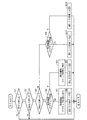
図8は、押しボタン22の操作に基づく前記CPU30の処理を示すフローチャートである。図8において、ステップS1では、押しボタン22が押されたか否かが判断され、この判断が肯定ならば、ステップS2に進む。ステップS2では、押しボタン22が予定の時間T(例えば0.1秒)以上継続して押されたかどうかが判断され、これが肯定ならば押しボタン22の操作は瞬時操作であると判断されてステップS3に進む。時間Tより短時間の操作はエラーとしてこのフローを抜ける。ステップS3では、第2の予定時間T1(T1>T:例えば1秒)以上継続して押しボタン22が押されたかどうかが判断され、これが肯定ならば長時間操作(長押し)であると判断されてステップS4に進む。
FIG. 8 is a flowchart showing the processing of the
ステップS4では、現在のリモートキー100の受信回路26がアクティブか、つまり受信待ち受け状態か否かが判断される。アクティブであれば、ステップS5に進んで受信回路26をストップつまり機能停止状態に移行させる。そして、機能停止状態に移行したことを示すため、ステップS6に進んで赤色LED24を点灯させる。ここでの点灯状態は予定の短時間で終了される。つまり瞬間だけ赤色LEDが点灯される。
In step S4, it is determined whether the receiving
一方、ステップS4が否定ならば、ステップS7に進んで受信回路26をアクティブ状態に移行させる。そして、受信待ち受け態に移行したことを示すため、ステップS8に進んで緑色LED23を点灯させる。ここでの点灯状態は予定の短時間で終了される。つまり瞬間だけ緑色LED23が点灯される。
On the other hand, if step S4 is negative, the process proceeds to step S7 to shift the receiving
また、ステップS3が否定の場合、つまり長押しには至らない短時間操作である場合は、ステップS9に進み、受信待ち受け状態か否かが判断される。ステップS9が肯定ならば、ステップS10に進み、受信回路26は受信待ち受け状態であることを示すため緑色LED23を点滅させる。点滅回数は、例えば4回とする。ステップS9が否定ならばステップS11に進み、受信回路26は機能停止状態であることを示すため赤色LED24を点滅させる。点滅回数は、例えば4回とする。
If step S3 is negative, that is, if the operation is a short-time operation that does not result in a long press, the process proceeds to step S9, where it is determined whether or not a reception standby state is set. If step S9 is affirmative, the process proceeds to step S10, and the receiving
次のいずれかの処置を行うことによって、受信回路26を停止状態にすることができる。第1に、受信回路26の電源を遮断する。第2に、たとえ受信したとしてもCPU30を起動させない。つまりランモードにしない。第3に、CPU30が起動されても、ID情報の照合処理を実行させない。
The receiving
図6のキーレスエンジン始動システムは、前記押しボタン22が操作され、リモートキー100の受信回路26がアクティブになっていて、かつ前記リモートキー100を持って車両に設定された認証エリアに入ったときにシステム全体が動作する。そして受信回路26が停止状態であるときには動作しない。したがって、リモートキーを持って前記認証エリア外に出ているとき、キーレスエンジン始動システムは初期状態にあり各ロック装置が施錠されている
The keyless engine starting system shown in FIG. 6 is operated when the
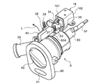
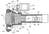
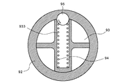
図1は、ハンドルロックモジュールの外観斜視図、図2は断面図、図3は、図2のA−A断面図である。これらの図において、ハンドルロックモジュール9には、前記自動二輪車のパネル4にこのハンドルロックモジュール9を装着するためのフランジ90を有する。フランジ90にはノブスイッチ10を構成する筒状のハウジング91の端部が嵌合され、ハウジング91内にはノブ92および回動軸93が嵌挿されている。回動軸93の頭部つまりノブ92寄りの太径部932には、回動軸93を直径方向に横切る有底のばね収容孔933が形成され、このばね収容孔933にはコイルばね94およびばね94の先端に当接するクリックボール95が収容される。
1 is an external perspective view of the handle lock module, FIG. 2 is a cross-sectional view, and FIG. 3 is a cross-sectional view taken along the line AA of FIG. In these drawings, the
クリックボール95は、ノブ92の筒状延長部921の内面に当接し、ばね94の反発力で押圧されている。ノブ92の筒状延長部921の内面には、ノブ92の初期位置つまりロック位置(後述)に回動されているときにクリックボール95が嵌合する凹部922を有する。クリックボール95と凹部922とは、互いに係合してトルクリミッタ機構として機能する。
The
クリックボール95と凹部922との係合部は、ノブ92を通常に操作するときに加わると予定されるトルク以上のトルクであって、後述の係止爪33と回動軸93との係合が強引に外されるトルク、具体的には係止爪33を破損させる強度を発生させるトルク未満のトルクがかかったときに互いの係合が外れるようにばね94のばね定数やボールの大きさ、並びに凹部922の形状などを設計する。
The engagement portion between the
ノブ92は、フランジ90からわずかに突出しているだけであり、実質的にフランジと面一であるので、指以外の工具等で操作しにくい形状である。
The
回動軸93の後端つまりノブ92から遠い側には、回動軸93に対して偏心した連結軸96を有するクランク部97が設けられる。連結軸96は、ハンドルロックのロックバー32に連結される。したがって、回動軸93の回動に伴って連結軸96が回動軸93の中心軸に対して変位する。ロックバー32はその変位に応じてハンドル2のシャフトに離接し、ハンドル2の施錠・解錠動作を行う。
A
この回動軸93の回動を規制して、ノブスイッチ10の操作を禁止するとともに、ハンドルロックの解除を禁止するための係合装置つまりソレノイド16と係止爪33が設けられる。ソレノイド16のプランジャ161はリンク34に係合され、リンク34にはハウジング91を貫通して回動軸93の係止溝934に係合される係止爪33が結合される。この係止爪33は、ノブスイッチ10がロック位置にあるときに係止溝934に係合する。
An engaging device, that is, a
リンク34は支持軸35によってソレノイド16の外皮ケース162に支持される。支持軸35の延長上には緊急解除用爪36が回動自在に設けられる。爪33および36はいずれもコイルばね37,38でそれぞれ下方に付勢されている。緊急解除用爪36は緊急解除用キーシリンダ39から延長されるリンク40の上面に当接している。
The
ソレノイド16が通電されていないとき、つまり解錠操作されていない状態では、プランジャ161は自由に動くので、係止爪33は、コイルばね37によって回動軸93側に付勢され、係止溝934に押圧されている。リモートキー100とハンドルロックモジュール9との間でID情報の認証が成立すると、ソレノイド16が駆動されて、プランジャ161は引き込まれてリンク34が支持軸35を中心に回動する。その結果、係止爪33は係止溝934から外れて、回動軸93は回動可能となり、ノブスイッチ10は操作許可状態になる。
When the
リモートキー100による解錠が不能な場合に緊急解除用キー(図示しない)が使用される。緊急解除用キーは緊急解除用キーシリンダ39に差し込んで使用される。緊急解除用キーを回すと、リンク40が図1の矢印Lの方向に回動して緊急解除用爪36を上方に押し上げる。これによって、緊急解除用爪36の端部作動部361がリンク34に当接してプランジャ161をソレノイド16内に押し込む。これにより、ソレノイド16が駆動されたのと同様に、係止爪33が持ち上げられる。
When unlocking with the
正規な操作でソレノイド16を駆動させないで、ノブスイッチ10を強制的に回動させようとした場合、係止爪33が回動軸に作用しているので、ノブスイッチ10は回動できない。これをさらに、工具などを使ってより強大な力で回動させようとすると、クリックボール95が溝92から外れてノブ92は回動軸93に対して空回りする。
When the
ノブ92は、空回りして、1回転すると再びクリックボール95が溝92と嵌合するので、係止爪33が外れた状態においては通常の操作トルクで回動軸93を回動させることができる。
When the
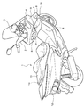
図4はノブスイッチ10の一例を示す図である。図4において、ノブスイッチ10は、初期状態ではロック位置にある。この状態ではノブスイッチ10は施錠されていて、押し込み操作は可能であるが回動は不能である。ノブスイッチ10を押すとリモートキー100との通信が開始され、ID情報の照合が成立すれば、回動可能になる。ノブスイッチ10をオン位置まで回すと、ECU19と通信してID情報の照合が行われる。ECU19とハンドルロックモジュール9との間でID情報の照合が成立すれば、ハンドルロックは解錠され、エンジンは始動許可状態となり、シートロック装置14を解錠させるスイッチ11の機能も活性化される。そして、ノブスイッチ10に隣接されるイグニッションスイッチ41を押すとエンジンの始動動作、つまりエンジン始動用モータの駆動、燃料噴射、および点火動作等が開始される。なお、イグニッションスイッチ41をノブスイッチ10と別に設けるのに代えて、ノブスイッチ10に始動位置(イグニッション位置)を設定するようにしてもよい。また、ハンドルのグリップ近傍に始動用スイッチを別途設けてもよい。
FIG. 4 is a diagram illustrating an example of the
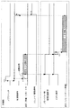
図9はキーレスエンジン始動システムの動作を示すタイミングチャートである。図6および図9を参照してキーレスエンジン始動システムの全体動作を説明する。まず、時期t0でノブスイッチ10を押すと制御部15が立ち上がる。そして時期t1で制御部15から起動信号が出力され、時期t2でID情報が送信される。
FIG. 9 is a timing chart showing the operation of the keyless engine starting system. The overall operation of the keyless engine starting system will be described with reference to FIGS. First, when the
前記制御部15の起動信号に応答してリモートキー100側の受信回路26が立ち上がり、同時にリモートキー100のCPU30も立ち上がる。そして、時期t3までにID情報を受信したリモートキー100は、時期t4でID情報を送出する。制御部15では送信したID情報と受信したID情報とを照合し、照合が成立すると、時期t5でソレノイド16を動作させてノブスイッチ10の回動規制を解除させる。ノブスイッチ10の回動規制が解除されるとともに、シート解錠用スイッチ11が動作可能になり、このシート解錠用スイッチ11を押すことによってシートロック装置14を解錠するためのソレノイド20が動作する。
In response to the activation signal of the
本実施形態では、クリックボールを1個だけ設けた例を示したが、複数設けるようにしてもよい。 In this embodiment, an example in which only one click ball is provided is shown, but a plurality of click balls may be provided.
また、本発明は、上述の自動二輪車に限らず、4輪車、農作業機、建設機械等、ノブスイッチが覆われていない車両に広く使用できる。なお、ノブスイッチはこれに限定されない、要はキーレス始動装置用のスイッチとして使用されるものであればよい。 Further, the present invention is not limited to the motorcycle described above, and can be widely used for vehicles in which the knob switch is not covered, such as a four-wheeled vehicle, an agricultural machine, and a construction machine. The knob switch is not limited to this, and any key switch may be used as long as it is used as a switch for a keyless starter.
9…ハンドルロックモジュール、 10…エンジン始動用スイッチ(ノブスイッチ)、 15…制御部、 22…押しボタン、 23,24…表示灯、 26…受信回路、 92…操作ノブ、 93…回動軸、 95…クリックボール、 100…リモートキー
DESCRIPTION OF
Claims (4)
前記回動軸の外周に沿って回動自在に嵌合された筒状部および該筒状部につながる操作部からなる操作ノブと、
前記操作ノブが所定のロック位置にあるときに回動軸の外周に爪部材を係合させて該回動軸の回動を規制し、外部からの解除信号に応答して規制を解除する電磁式アクチュエータ手段と、
前記操作部および前記回動軸を連結するトルクリミッタ機構とを備え、
前記トルクリミッタ機構が、
前記回動軸を直径方向に横断して延在しているばねと、
前記回動軸に収容されて該回動軸の外周方向に前記ばねによって付勢されたクリックボールと、
前記クリックボールが嵌合するように前記操作ノブの筒状部に形成された凹部とからなるとともに、
前記トルクリミッタ機構のトルク制限値が、前記ノブの、予定回動操作トルク以上であって、前記爪部材と前記回動軸との係合強度未満であることを特徴とする車両用ロック装置。 A pivot shaft coupled to the handle lock to displace the vehicle handle lock to a locked and unlocked position;
An operation knob comprising a cylindrical portion fitted so as to be rotatable along the outer periphery of the rotation shaft and an operation portion connected to the cylindrical portion;
An electromagnetic that restricts the rotation of the rotation shaft by engaging a claw member with the outer periphery of the rotation shaft when the operation knob is at a predetermined lock position, and releases the restriction in response to a release signal from the outside. Actuator means;
A torque limiter mechanism that connects the operation unit and the rotation shaft;
The torque limiter mechanism is
A spring extending diametrically across the pivot axis;
A click ball accommodated in the rotating shaft and biased by the spring in an outer peripheral direction of the rotating shaft;
It consists of a recess formed in the cylindrical part of the operation knob so that the click ball fits,
The vehicle lock device according to claim 1, wherein a torque limit value of the torque limiter mechanism is equal to or greater than a predetermined rotation operation torque of the knob and less than an engagement strength between the claw member and the rotation shaft.
車両のECUと通信して車両の始動許可を与えるイモビライザー用送受信回路と、
車両に設けられる収容室の蓋を兼ねるシートのロック装置を解錠するシート解錠スイッチとをさらに備えたことを特徴とする請求項1〜請求項3のいずれかに記載の車両用ロック装置。 An emergency release mechanism for releasing the engagement of the claw member in an emergency instead of the electromagnetic actuator;
An immobilizer transmission / reception circuit that communicates with the vehicle's ECU to give vehicle start permission;
The vehicle locking device according to any one of claims 1 to 3 , further comprising a seat unlocking switch for unlocking a seat locking device that also serves as a lid of a storage chamber provided in the vehicle.
Priority Applications (7)
| Application Number | Priority Date | Filing Date | Title |
|---|---|---|---|
| JP2003346194A JP4100570B2 (en) | 2003-10-03 | 2003-10-03 | Vehicle locking device |
| TW93129321A TWI273060B (en) | 2003-10-03 | 2004-09-29 | Vehicle locking apparatus |
| KR1020040078210A KR100606483B1 (en) | 2003-10-03 | 2004-10-01 | Vehicle locking apparatus |
| US10/954,655 US7591158B2 (en) | 2003-10-03 | 2004-10-01 | Vehicle locking apparatus |
| DE200460011161 DE602004011161T2 (en) | 2003-10-03 | 2004-10-04 | Kraftfahrzeugschliessanlage |
| EP20040023624 EP1520757B1 (en) | 2003-10-03 | 2004-10-04 | Vehicle locking apparatus |
| CNB2004100834226A CN100486857C (en) | 2003-10-03 | 2004-10-08 | Vehicle locking apparatus |
Applications Claiming Priority (1)
| Application Number | Priority Date | Filing Date | Title |
|---|---|---|---|
| JP2003346194A JP4100570B2 (en) | 2003-10-03 | 2003-10-03 | Vehicle locking device |
Publications (3)
| Publication Number | Publication Date |
|---|---|
| JP2005112048A JP2005112048A (en) | 2005-04-28 |
| JP2005112048A5 JP2005112048A5 (en) | 2005-12-02 |
| JP4100570B2 true JP4100570B2 (en) | 2008-06-11 |
Family
ID=34309174
Family Applications (1)
| Application Number | Title | Priority Date | Filing Date |
|---|---|---|---|
| JP2003346194A Expired - Lifetime JP4100570B2 (en) | 2003-10-03 | 2003-10-03 | Vehicle locking device |
Country Status (7)
| Country | Link |
|---|---|
| US (1) | US7591158B2 (en) |
| EP (1) | EP1520757B1 (en) |
| JP (1) | JP4100570B2 (en) |
| KR (1) | KR100606483B1 (en) |
| CN (1) | CN100486857C (en) |
| DE (1) | DE602004011161T2 (en) |
| TW (1) | TWI273060B (en) |
Families Citing this family (47)
| Publication number | Priority date | Publication date | Assignee | Title |
|---|---|---|---|---|
| KR100635253B1 (en) * | 2004-06-03 | 2006-10-19 | 주식회사 신창전기 | 2 mode ignition switch apparatus |
| JP4767593B2 (en) * | 2005-06-02 | 2011-09-07 | 株式会社ホンダロック | Ignition switch operating device for vehicle |
| DE102005038437A1 (en) * | 2005-08-12 | 2007-02-15 | Huf Hülsbeck & Fürst GmbH & Co KG | Ignition device for an engine, in particular in a motor vehicle |
| CN1958378B (en) * | 2005-10-31 | 2011-07-06 | 东洋建苍电机股份有限公司 | Induction type main switch lock for motorcycle |
| US7730752B2 (en) * | 2006-03-13 | 2010-06-08 | Kawasaki Jukogyo Kabushiki Kaisha | Theft prevention apparatus for leisure vehicle |
| JP4802827B2 (en) * | 2006-04-06 | 2011-10-26 | スズキ株式会社 | Emergency unlocking system for motorcycles |
| ITRM20070191A1 (en) | 2006-04-06 | 2007-10-07 | Suzuki Motor Corp | ELECTRONIC AUTHENTICATION SYSTEM FOR MOTORCYCLE |
| WO2007142405A1 (en) * | 2006-06-07 | 2007-12-13 | Eung Lyul Kim | Steering lock device for coupling electronic identification system and method of manufacturing thereof |
| JP4902386B2 (en) * | 2007-02-13 | 2012-03-21 | 朝日電装株式会社 | Ignition switch device |
| JP5286583B2 (en) | 2007-03-16 | 2013-09-11 | ヤマハ発動機株式会社 | Motorcycle |
| EP1970295B1 (en) | 2007-03-16 | 2017-06-07 | Yamaha Hatsudoki Kabushiki Kaisha | Motorcycle locking mechanism |
| JP5164402B2 (en) * | 2007-03-16 | 2013-03-21 | ヤマハ発動機株式会社 | Motorcycle |
| CN101311056B (en) * | 2007-05-25 | 2010-06-09 | 精工电机股份有限公司 | No-key vehicle tap lock |
| JP4994954B2 (en) * | 2007-05-28 | 2012-08-08 | 朝日電装株式会社 | Ignition switch device |
| KR100820859B1 (en) * | 2007-07-31 | 2008-04-11 | 양재우 | Structure of automobile electronic key for security |
| JP2009262605A (en) * | 2008-04-22 | 2009-11-12 | Asahi Denso Co Ltd | Engine starting device |
| DE102008023490A1 (en) * | 2008-05-14 | 2009-11-19 | GM Global Technology Operations, Inc., Detroit | Lock of a Hauber of a motor vehicle |
| JP5191415B2 (en) * | 2009-02-24 | 2013-05-08 | 朝日電装株式会社 | Ignition switch device |
| US8677792B2 (en) * | 2009-02-25 | 2014-03-25 | Adams Rite Manufacturing Co. | Electronic door lock apparatus |
| JP2011027085A (en) | 2009-07-29 | 2011-02-10 | Honda Lock Mfg Co Ltd | Engine start/stop switch device |
| US8943864B2 (en) * | 2010-01-18 | 2015-02-03 | Liberty Safe And Security Products, Inc. | Proportional torque shaft clutch assembly |
| JP5507342B2 (en) * | 2010-05-26 | 2014-05-28 | 株式会社東海理化電機製作所 | Ignition switch operation restriction device |
| JP5611752B2 (en) * | 2010-10-07 | 2014-10-22 | 株式会社東海理化電機製作所 | Ignition switch operation restriction device |
| DE102012023772A1 (en) * | 2012-12-05 | 2014-06-05 | GM Global Technology Operations LLC (n. d. Ges. d. Staates Delaware) | Switching device for a motor vehicle |
| CN103359202B (en) * | 2013-07-16 | 2015-06-24 | 陶金刚 | Hand-pressing slope-contact faucet lock of electric vehicle |
| JP5878151B2 (en) * | 2013-09-30 | 2016-03-08 | 本田技研工業株式会社 | Vehicle smart lock module |
| US9512642B2 (en) * | 2014-03-07 | 2016-12-06 | Keyless.Co, Llc | Reprogrammable cylinder lock |
| SE538924C2 (en) * | 2015-06-25 | 2017-02-21 | Scania Cv Ab | Start/stopp switch system, primarily intended for a vehicle |
| JP6586309B2 (en) * | 2015-07-09 | 2019-10-02 | 朝日電装株式会社 | Saddle type vehicle authentication operation device and saddle type vehicle |
| JP6228952B2 (en) * | 2015-07-09 | 2017-11-08 | ヤマハ発動機株式会社 | Saddle type vehicle authentication system and saddle type vehicle |
| JP6228951B2 (en) * | 2015-07-09 | 2017-11-08 | ヤマハ発動機株式会社 | Saddle type vehicle authentication system and saddle type vehicle |
| DE102015224108A1 (en) * | 2015-12-02 | 2017-06-08 | Bayerische Motoren Werke Aktiengesellschaft | Control device and control method for a vehicle with automatically opening and / or automatically closing flap |
| DE102016108565A1 (en) * | 2016-05-10 | 2017-11-16 | Huf Hülsbeck & Fürst Gmbh & Co. Kg | Implementation element for an electric steering lock |
| JP6166427B1 (en) * | 2016-06-02 | 2017-07-19 | 株式会社東海理化電機製作所 | Steering lock device |
| EP3339110B1 (en) | 2016-12-22 | 2020-02-05 | Asahi Denso Co., Ltd. | Engine starting device |
| JP6851044B2 (en) | 2016-12-22 | 2021-03-31 | 朝日電装株式会社 | Engine starter |
| EP3600977B1 (en) * | 2017-03-29 | 2022-09-07 | Minda Corporation Limited | Smart cylinder lock device |
| US10501050B2 (en) * | 2017-06-30 | 2019-12-10 | GM Global Technology Operations LLC | Vehicle ignition system |
| JP6811159B2 (en) * | 2017-10-31 | 2021-01-13 | 本田技研工業株式会社 | Handle lock device for saddle-mounted vehicles |
| WO2019092740A1 (en) * | 2017-11-07 | 2019-05-16 | Minda Corporation Limited | A multi-function smart ignition lock for vehicles |
| WO2019193613A1 (en) * | 2018-04-06 | 2019-10-10 | Minda Corporation Limited | Keyless lock for vehicles |
| CN108979342B (en) * | 2018-08-02 | 2020-06-16 | 南通福特德尔智能科技有限公司 | Fingerprint password lock body |
| JP7016792B2 (en) * | 2018-12-25 | 2022-02-07 | 株式会社ホンダロック | Handle lock device |
| CN113573973B (en) * | 2019-03-29 | 2023-04-04 | 本田技研工业株式会社 | Unlocking system |
| CN114078651A (en) * | 2020-08-21 | 2022-02-22 | 东洋建苍电机股份有限公司 | Rotary main switch lock |
| CN114753722B (en) * | 2021-01-08 | 2023-06-30 | 东洋建苍电机股份有限公司 | Lockset, linkage module and locking module thereof |
| WO2022196742A1 (en) * | 2021-03-18 | 2022-09-22 | 本田技研工業株式会社 | Vehicle operation device and handle lock device |
Family Cites Families (26)
| Publication number | Priority date | Publication date | Assignee | Title |
|---|---|---|---|---|
| US1671521A (en) * | 1926-11-26 | 1928-05-29 | Mccrosky Tool Corp | Shaft coupling |
| JPS60119873A (en) * | 1983-11-29 | 1985-06-27 | 日産自動車株式会社 | Locking controller for vehicle |
| JPS6339069A (en) | 1986-08-04 | 1988-02-19 | Matsushita Electric Ind Co Ltd | Periodical interruption informing method for digital input/output controller |
| JP2523145B2 (en) | 1987-11-17 | 1996-08-07 | 東京エレクトロン東北株式会社 | Pusher for object to be processed |
| CA1308762C (en) * | 1988-05-12 | 1992-10-13 | Aaron M. Fish | Cylindrical and permutation lock arrangements |
| AU626166B2 (en) * | 1990-01-31 | 1992-07-23 | Suzuki Kabushiki Kaisha | Electric circuit system for motorcycle |
| US5656867A (en) * | 1995-04-11 | 1997-08-12 | Kabushiki Kaisha Tokai-Rika-Denki-Seisakusho | Vehicular starting control device using an ID code to control ignition switch rotation and steering lock operation |
| JP3519494B2 (en) | 1995-04-11 | 2004-04-12 | 株式会社東海理化電機製作所 | Vehicle start control device |
| JP3275777B2 (en) | 1997-05-19 | 2002-04-22 | トヨタ自動車株式会社 | Smart entry system |
| JPH10315914A (en) * | 1997-05-19 | 1998-12-02 | Tokai Rika Co Ltd | Starter for vehicle |
| AU7628398A (en) * | 1997-09-12 | 1999-03-25 | Robert Bosch Gmbh | An ignition lock system |
| US6105405A (en) * | 1998-11-25 | 2000-08-22 | Wesko Systems Limited | Locking apparatus having a unitary driver |
| US6442985B1 (en) * | 1999-06-11 | 2002-09-03 | Nissan Motor Co., Ltd. | Lock apparatus and lock system |
| US6257031B1 (en) * | 1999-06-30 | 2001-07-10 | The Eastern Company | Ignition lock operable when key is removed |
| FR2805231B1 (en) * | 2000-02-23 | 2002-05-10 | Valeo Securite Habitacle | IMPROVED ELECTRONIC ANTI-THEFT SYSTEM FOR A MOTOR VEHICLE |
| DE10106123B4 (en) | 2001-02-08 | 2011-06-01 | Leopold Kostal Gmbh & Co. Kg | Electric / electronic switching system for motor vehicles |
| JP4590116B2 (en) | 2001-02-19 | 2010-12-01 | 本田技研工業株式会社 | Remote lock operation device for light vehicle |
| US6527314B2 (en) * | 2001-02-20 | 2003-03-04 | Jackson Corporation | Clutch handle |
| JP2002308049A (en) * | 2001-04-11 | 2002-10-23 | Tokai Rika Co Ltd | Engine starting device for vehicle |
| GB2376044B (en) * | 2001-06-01 | 2005-05-25 | Tokai Rika Co Ltd | Steering wheel locking device |
| JP2003064918A (en) | 2001-08-24 | 2003-03-05 | Fuji Heavy Ind Ltd | Keyless entry system of automobile |
| JP3845323B2 (en) | 2002-03-11 | 2006-11-15 | 本田技研工業株式会社 | Vehicle engine starting system |
| DE60308101T2 (en) * | 2002-05-29 | 2007-05-10 | Kabushiki Kaisha Tokai Rika Denki Seisakusho | Device for preventing the activation of an engine starting system |
| KR20030096944A (en) * | 2002-06-18 | 2003-12-31 | 현대자동차주식회사 | Burglarproof system of a vehicle |
| US6941779B2 (en) * | 2002-07-30 | 2005-09-13 | Kabushiki Kaisha Honda Lock | Steerage locking system for vehicle |
| US7277007B2 (en) * | 2003-05-16 | 2007-10-02 | Lear Corporation | Keyless smart start system |
-
2003
- 2003-10-03 JP JP2003346194A patent/JP4100570B2/en not_active Expired - Lifetime
-
2004
- 2004-09-29 TW TW93129321A patent/TWI273060B/en not_active IP Right Cessation
- 2004-10-01 KR KR1020040078210A patent/KR100606483B1/en active IP Right Grant
- 2004-10-01 US US10/954,655 patent/US7591158B2/en not_active Expired - Fee Related
- 2004-10-04 EP EP20040023624 patent/EP1520757B1/en not_active Expired - Fee Related
- 2004-10-04 DE DE200460011161 patent/DE602004011161T2/en active Active
- 2004-10-08 CN CNB2004100834226A patent/CN100486857C/en active Active
Also Published As
| Publication number | Publication date |
|---|---|
| TW200514719A (en) | 2005-05-01 |
| KR100606483B1 (en) | 2006-08-01 |
| KR20050033441A (en) | 2005-04-12 |
| EP1520757A1 (en) | 2005-04-06 |
| US20050115757A1 (en) | 2005-06-02 |
| TWI273060B (en) | 2007-02-11 |
| CN1607141A (en) | 2005-04-20 |
| DE602004011161T2 (en) | 2009-01-15 |
| CN100486857C (en) | 2009-05-13 |
| JP2005112048A (en) | 2005-04-28 |
| US7591158B2 (en) | 2009-09-22 |
| DE602004011161D1 (en) | 2008-02-21 |
| EP1520757B1 (en) | 2008-01-09 |
Similar Documents
| Publication | Publication Date | Title |
|---|---|---|
| JP4100570B2 (en) | Vehicle locking device | |
| JP4100568B2 (en) | Vehicle remote key | |
| US7730752B2 (en) | Theft prevention apparatus for leisure vehicle | |
| US7071819B2 (en) | Remote control lock operation system for vehicles | |
| US20070247280A1 (en) | Electronic authentication system for motorcycle | |
| US7190255B2 (en) | Anti-theft device in motorcycle | |
| JP4958590B2 (en) | Leisure vehicle anti-theft device | |
| JP3875706B2 (en) | Engine start system | |
| JP2006273026A (en) | Smart keyless system | |
| JP4094869B2 (en) | Engine start control device | |
| JP4733449B2 (en) | Ignition switch device | |
| JP2022056165A (en) | Lock device for vehicle | |
| JP2009202718A (en) | Electric steering lock device for vehicle | |
| JP2009262605A (en) | Engine starting device | |
| JP2000087608A (en) | Lock device for bicycle | |
| JP4925324B2 (en) | Ignition switch device | |
| JP3423899B2 (en) | Steering lock device | |
| JP4902386B2 (en) | Ignition switch device | |
| JP2676411B2 (en) | Handle lock device and engine ignition device | |
| JP4733450B2 (en) | Ignition switch device | |
| JP4657837B2 (en) | Ignition switch device | |
| JPH0657524B2 (en) | Vehicle theft prevention device | |
| JP2010047051A (en) | Power source status switching device | |
| JP2003341477A (en) | Operation restricting device of engine starting system | |
| JPH0555339B2 (en) |
Legal Events
| Date | Code | Title | Description |
|---|---|---|---|
| A521 | Request for written amendment filed |
Free format text: JAPANESE INTERMEDIATE CODE: A523 Effective date: 20051012 |
|
| A621 | Written request for application examination |
Free format text: JAPANESE INTERMEDIATE CODE: A621 Effective date: 20051012 |
|
| A977 | Report on retrieval |
Free format text: JAPANESE INTERMEDIATE CODE: A971007 Effective date: 20070725 |
|
| A131 | Notification of reasons for refusal |
Free format text: JAPANESE INTERMEDIATE CODE: A131 Effective date: 20070801 |
|
| A521 | Request for written amendment filed |
Free format text: JAPANESE INTERMEDIATE CODE: A523 Effective date: 20071001 |
|
| TRDD | Decision of grant or rejection written | ||
| A01 | Written decision to grant a patent or to grant a registration (utility model) |
Free format text: JAPANESE INTERMEDIATE CODE: A01 Effective date: 20080312 |
|
| A61 | First payment of annual fees (during grant procedure) |
Free format text: JAPANESE INTERMEDIATE CODE: A61 Effective date: 20080313 |
|
| FPAY | Renewal fee payment (event date is renewal date of database) |
Free format text: PAYMENT UNTIL: 20110328 Year of fee payment: 3 |
|
| R150 | Certificate of patent or registration of utility model |
Ref document number: 4100570 Country of ref document: JP Free format text: JAPANESE INTERMEDIATE CODE: R150 Free format text: JAPANESE INTERMEDIATE CODE: R150 |
|
| FPAY | Renewal fee payment (event date is renewal date of database) |
Free format text: PAYMENT UNTIL: 20110328 Year of fee payment: 3 |
|
| FPAY | Renewal fee payment (event date is renewal date of database) |
Free format text: PAYMENT UNTIL: 20120328 Year of fee payment: 4 |
|
| R250 | Receipt of annual fees |
Free format text: JAPANESE INTERMEDIATE CODE: R250 |
|
| FPAY | Renewal fee payment (event date is renewal date of database) |
Free format text: PAYMENT UNTIL: 20130328 Year of fee payment: 5 |
|
| R250 | Receipt of annual fees |
Free format text: JAPANESE INTERMEDIATE CODE: R250 |
|
| FPAY | Renewal fee payment (event date is renewal date of database) |
Free format text: PAYMENT UNTIL: 20130328 Year of fee payment: 5 |
|
| FPAY | Renewal fee payment (event date is renewal date of database) |
Free format text: PAYMENT UNTIL: 20140328 Year of fee payment: 6 |
|
| R250 | Receipt of annual fees |
Free format text: JAPANESE INTERMEDIATE CODE: R250 |
|
| R250 | Receipt of annual fees |
Free format text: JAPANESE INTERMEDIATE CODE: R250 |
|
| R250 | Receipt of annual fees |
Free format text: JAPANESE INTERMEDIATE CODE: R250 |
|
| R250 | Receipt of annual fees |
Free format text: JAPANESE INTERMEDIATE CODE: R250 |
|
| R250 | Receipt of annual fees |
Free format text: JAPANESE INTERMEDIATE CODE: R250 |
|
| R250 | Receipt of annual fees |
Free format text: JAPANESE INTERMEDIATE CODE: R250 |
|
| R250 | Receipt of annual fees |
Free format text: JAPANESE INTERMEDIATE CODE: R250 |
|
| R250 | Receipt of annual fees |
Free format text: JAPANESE INTERMEDIATE CODE: R250 |
|
| R250 | Receipt of annual fees |
Free format text: JAPANESE INTERMEDIATE CODE: R250 |
|
| R250 | Receipt of annual fees |
Free format text: JAPANESE INTERMEDIATE CODE: R250 |
|
| R250 | Receipt of annual fees |
Free format text: JAPANESE INTERMEDIATE CODE: R250 |
|
| EXPY | Cancellation because of completion of term |