JP4038143B2 - Digital camera - Google Patents
Digital camera Download PDFInfo
- Publication number
- JP4038143B2 JP4038143B2 JP2003083447A JP2003083447A JP4038143B2 JP 4038143 B2 JP4038143 B2 JP 4038143B2 JP 2003083447 A JP2003083447 A JP 2003083447A JP 2003083447 A JP2003083447 A JP 2003083447A JP 4038143 B2 JP4038143 B2 JP 4038143B2
- Authority
- JP
- Japan
- Prior art keywords
- digital camera
- spot
- image
- map
- tourist spot
- Prior art date
- Legal status (The legal status is an assumption and is not a legal conclusion. Google has not performed a legal analysis and makes no representation as to the accuracy of the status listed.)
- Expired - Fee Related
Links
Images


Landscapes
- Television Signal Processing For Recording (AREA)
- Studio Devices (AREA)
Description
【0001】
【発明の属する技術分野】
本発明はデジタルカメラに関し、詳しくは観光地やテーマパーク内で使用したときに、お薦めの撮影スポットで撮影の機会を逃すことがないようにしたデジタルカメラに関するものである。
【0002】
【従来の技術】
【特許文献1】
実開平6−69955号公報
【0003】
スチル画像あるいは動画撮影用、さらにはスチル・動画兼用型など様々な撮影機能をもったデジタルカメラが普及している。また、カメラの形態としても、通常の携帯型のものだけでなく、携帯電話に組み込まれたものもその普及が著しい。こうした背景の元、観光地やテーマパーク内などの特定エリア内でデジタルカメラを使用する機会も多くなってきている。ところが、このような特定エリアに関する情報が不十分であると、時として著名な撮影スポットで撮影する機会を逸してしまうことも少なくない。
【0004】
このため、観光地やテーマパークでは案内用のパンフレットを配布したり、入り口に案内板を設けたりしている。また、特定の観光地で使用されることを前提にして、レンズ付きフイルムユニットの包装袋にその観光地の案内地図を印刷しておくことが特許文献1に記載されている。その案内地図の中に撮影に適した特定スポットも併せて表示しておけば、そこでの撮影の機会を逸することも少なくなり便利である。
【0005】
【発明が解決しようとする課題】
しかし、案内板は限られた箇所にしか設置されていないのでいつでも見られるわけではない。また、案内パンフレットや開封済みの包装袋を持ち歩くことは煩わしく、しかも特定の撮影スポットに近づいたときに常にチェックできるわけでもない。さらに、レンズ付きフイルムユニットの包装袋に案内地図を印刷した場合、別の特定エリアでは新たなレンズ付きフイルムユニットを購入しなければならない。
【0006】
本発明は、上記の問題を解決するためになされたものであり、その目的は、ユーザに観光スポットの位置を容易に把握させ、さらに、観光スポットに気付かずに通り過ぎることを防止するデジタルカメラを提供することにある。
【0007】
【課題を解決するための手段】
上記目的を達成するために、本発明のデジタルカメラでは、特定エリア内に属する特定のスポットから無線で発信される前記特定スポット周辺の地図データを含む案内情報を受信する受信装置と、この受信装置で受信した案内情報に基づき、前記電子表示器に特定スポット周辺の地図を表示する表示制御手段とを備えるようにした。
【0008】
また、案内情報の受信に応答して着信報知を行う報知手段を備えるようにした。
【0009】
【発明の実施の形態】
図1に本発明を実施したデジタルカメラの斜視図を示す。デジタルカメラ2の上面には、電源スイッチ4が設けられており、このスイッチをスライド移動させて電源のON/OFFを行う。そのとなりには、シャッタボタン6が備えられている。シャッタボタン6の反対側には、撮像においてストロボのON/OFFを切り替えるストロボボタン7が備えられている。デジタルカメラ2の前面には、被写体をとらえる撮影レンズ8が露出している。撮影レンズ8の上方には対物ファインダ窓9が設けられ、その側方にはストロボ12が設けられている。
【0010】
筐体の側面にはアンテナ13が伸縮自在に備えられている。このアンテナ13は、観光スポットに設置された無線送信機から発信された所定の無線信号を受信するためのものである。この無線信号は、あらかじめ観光スポットに設置された無線送信機から発信されるものであり、観光スポットの案内情報である。この案内情報である無線信号には観光スポット周辺の地図データが含まれている。アンテナ13の下にはスピーカ14が備えられ、無線送信機から送信された無線信号を受信して、音を発するようになっている。これによりデジタルカメラ2の使用者は、観光スポットに接近したことを認識することができる。
【0011】
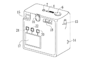
図2にデジタルカメラ2の背面の斜視図を示す。背面の図中左上には被写体を確認するための接眼ファインダ窓15が設けられており、その横には、デジタルカメラ2の各種設定が行えるモードダイヤル16が備えられている。モードダイヤル16の下には液晶画面17が設けられ、スルー画像や撮像した被写体画像などが表示される。また、メニューを選択する必要があるときは、モードダイヤル16の横にある選択ボタン18を用いて選択する。メニューの選択が終了したら実行ボタン20を押しメニューを実行に移す。実行ボタン20のとなりには取り消し動作を命令するキャンセルボタン22が備えられ、さらにそのとなりには、液晶画面17の表示/非表示を切り替える表示ボタン24が設けられている。
【0012】
図3に観光スポットに設置された無線送信機のブロック図を示す。この無線送信機30はあらかじめ観光スポットに設置されているものであり、他の観光スポットに設置されている無線送信機の構造も同様である。ROM32には、無線送信機が設置された場所の周辺の地図を画像表示させるための地図データが記憶されている。ROM32の地図データはメモリ34に一時的に蓄積され、その後、無線通信I/F36に入力される。ここで地図データは無線信号に変調され、アンテナ38から外部に送信される。また、無線送信機30の一連の動作は、CPU40により制御されている。
【0013】
無線信号を受信できるサービスエリアはあらかじめ決まっており、デジタルカメラ2は、このサービスエリア内にあるとき、無線信号を受信することができる。無線信号を受信したデジタルカメラ2は、無線信号を復調して地図データを読み出して、この地図データから作成した地図を画像表示する。
【0014】
図4に本発明が実施されたデジタルカメラ2のブロック図を示す。撮影レンズ8は、ズーム用の変倍レンズ、フォーカスレンズ、絞り、及び駆動モータを含んでいる。撮影レンズ8は、モータドライバ45よって駆動が制御されている。また、モータドライバ45は、CPU47によりさらに制御されている。
【0015】
撮影レンズ8の背後にはCCDイメージセンサ50が配置され、撮影レンズ8によって結像された被写体像を光電変換する。CCDイメージセンサ50は、各セルの電荷蓄積時間を変更することで、露光量を調節する電子シャッタとしての機能を備えている。CCDイメージセンサ50は、タイミングジェネレータ57から入力されたタイミング信号に基づいて動作する。
【0016】
光電変換によりCCDイメージセンサ50から出力された電気信号は、相関二重サンプリング回路(以下、CDSと省略する)52に入力される。CDS52は、CCDイメージセンサ50から入力された信号をRGBの画像信号に変換し、増幅回路(以下、AMPと省略する)54に入力する。AMP54でRGBの画像信号は増幅され、アナログ/デジタル変換器(以下、A/D変換器と省略する)55でデジタルデータに変換される。生成されたデジタルデータは、画像入力コントローラ57を介してバッファメモリ59に書き込まれ、ここに一時的に記録される。
【0017】
バッファメモリ59に書き込まれたデジタルデータは、画像処理回路61に入力され、ここでガンマ補正などの画像処理が施され、画像データが生成される。生成された画像データはバッファメモリ59に一時的に記録される。バッファメモリ59に書き込まれた画像データは、VRAM63や圧縮処理回路65に入力される。
【0018】
VRAM63に書き込まれた画像データはビデオエンコーダ67に入力される。ビデオエンコーダ67では、画像データがNTSCコンポジット信号に変換される。NTSCコンポジット信号は液晶画面17に入力され、液晶画面17に被写体画像が表示される。
【0019】
圧縮処理回路65に入力された画像データは、デジタルカメラ2の画質設定に応じてJoint Photographic Experts Group(以下、JPEGと省略する)の規格に準拠して圧縮される。そして、メディアコントローラ70に入力される。メディアコントローラ70に入力された画像データは、記録メディア72に記録される。このとき画像データはDCF (Design rule for Camera File system)規格に準拠した画像ファイルを形成している。
【0020】
デジタルカメラ2は、モードダイヤル16の操作により、デジタルカメラ2のモードが静止画を取り込むカメラモードと、撮像した画像を液晶画面17で確認できるリプレイモードとに切り替えられる。カメラモードのとき、シャッタボタン6が押下されるとシャッタスイッチが閉じて画像の取り込みが開始される。リプレイモードのときは、記録メディア72からVRAM63に画像ファイルが読み出され、NTSCコンポジット信号に変換され、液晶画面17に被写体画像が表示される。
【0021】
デジタルカメラ2が無線信号のサービスエリア内にあるとき、アンテナ13は観光スポットに設置された無線送信機30から送信された無線信号を受信し、受信された無線信号は無線通信インターフェース(以降、無線通信I/Fと省略する)75に入力される。無線通信I/F75で無線信号は復調され、無線信号に含まれた観光スポット周辺の地図データが読み出される。地図データはバッファメモリ59に一時的に蓄積され、その後、VRAM63に入力されてビデオエンコーダ67においてNTSCコンポジットデータに変換される。このNTSCコンポジットデータが液晶画面17に入力され、液晶画面17に観光スポット周辺の地図が表示される。
【0022】
また、無線信号をアンテナ13が受信するとともに、CPU47に信号を入力し、CPU47はスピーカ14に音声信号を入力し、スピーカ14はビーコン音を発する。また、スピーカ14から音が出ないようにデジタルカメラ2を消音モードにしているときは、CPU47からの信号の入力に応答して振動モータ77が動作を行い、デジタルカメラ2が振動するようになっている。このようにして観光スポットに接近したことが使用者に通知される。
【0023】
次に上記構成の作用について説明する。観光スポットにはあらかじめ無線信号を発信する無線送信機30が設置されており、発信される無線信号には観光スポット周辺の地図データが含まれている。無線送信機30から発信された無線信号を受信できるサービスエリアは決まっており、サービスエリア以外では無線信号を受信することできない。また、無線信号は決められたデジタルカメラにしか受信できないように、あらかじめ送受信方式が決められている。
【0024】
デジタルカメラ2に備えられたアンテナ13が、無線送信機から発信された無線信号を受信し、受信された信号は無線通信I/F75に入力される。このとき、無線信号の受信とともにCPU47に信号が入力され、スピーカ14からはビーコン音が発せられて観光スポットに接近したことが使用者に通知される。また、スピーカ14が消音モードになっているときは、振動モータ77が作動してデジタルカメラ2が振動するようになっている。無線通信I/F75では無線信号が復調され、観光スポット周辺の地図データが抽出される。取り出された地図データはバッファメモリ59に一時的に記憶され、使用者のボタン操作によりVRAM63に入力される。
【0025】
VRAM63に入力された地図データはビデオエンコーダ67に送られて、NTSCコンポジット信号に変換される。このNTSCコンポジット信号が液晶画面17に入力され、液晶画面17には観光スポット周辺の地図が表示される。
【0026】
液晶画面17に表示された観光スポット周辺の地図を図5に示す。表示された地図は、無線送信機30から発信された無線信号から読み出された地図データによって形成されたものであり、観光スポットAに設置された無線送信機から発信された無線信号より作成されたものである。観光スポットAの周辺には、観光スポットBと、観光スポットCと、観光スポットDとが存在していることが示されている。
【0027】
観光スポットBと、観光スポットCと、観光スポットDとからも無線信号が発信されており、液晶画面17の右には無線信号を受信したリスト80が表示されている。リスト80には上下に動かせるカーソル82が示されている。このカーソル82を選択ボタン18で動かし、実行ボタン20を押して実行すると、選択された観光スポットの周辺の地図データがVRAM63に入力され、液晶画面17には、選択した観光スポットの周辺の地図が新規に表示される。例えば、カーソル82をリスト80の一番下にある観光スポットDに合わせて実行すると、図6に示すように、観光スポットDの周辺の地図が表示される。
【0028】
なお、上記の実施例では、観光スポットAの周辺にある観光スポットのそれぞれに設置された無線送信機が無線信号を発信するようにしたが、観光スポットAのみがこの周辺のエリアを代表して無線信号を発信するようにしてもよい。観光スポットAに設置した発信機がこのエリアを代表して無線信号を発信することにより、周辺の観光スポットに設置する発信機の数を減らすことができ、発信機の設置コストを少なくすることができる。
【0029】
また、GPS(Global Positioning System) と、磁気方位センサやジャイロセンサなどのセンサ類とを利用して、現在位置の情報を取得し、液晶画面に表示された地図上に現在位置を表示するようにしてもよい。GPS衛星からの位置情報を含んだ電波をアンテナで受信し、無線通信I/Fにおいて復調し、取得した位置データをバッファメモリに記憶する。同時にジャイロセンサと磁気センサとから位置データに関する補正データを取得し、バッファメモリに記録する。そして、VRAMに位置データと補正データとを読み出し、ビデオエンコーダを介して液晶画面に現在位置を表示することも可能である。
【0030】
また、デジタルカメラが無線信号を受信するための通信ソフトや、無線信号を基にしてデジタルカメラの液晶画面に地図を表示するための表示ソフトは、観光スポットの案内所や入口でダウンロードするか、あるいはインターネットで予めダウンロードするようにしてもよい。
【0031】
また、液晶画面で観光スポットの周辺の地図を確認する代わりに、デジタルカメラのファインダを覗き込んで観光スポットの周辺の地図を確認するようにしてもよい。デジタルカメラ内部に液晶画面を内蔵させ、この液晶画面に観光スポットの周辺の地図を表示し、これをファインダから見ることで、観光スポット周辺の地図を確認することができる。
【0032】
なお、上記実施形態では、デジタルカメラを示したが、本発明はこれに限らず、カメラ付き携帯電話に実施してもよい。この場合にもカメラ付き携帯電話のアンテナで無線信号を受信し、備え付けの液晶画面に観光スポットの周辺の地図を表示することができる。
【0033】
【発明の効果】
以上のように、本発明のデジタルカメラによれば、案内情報を受信する受信装置と、受信した案内情報に基づき特定スポット周辺の地図を表示する表示手段とを有することにより、使用者に特定スポットの場所を認識させることができる。このため使用者を特定スポットに容易に到達させることができる。また、特定スポットに接近したことが通知されることにより、特定スポットに気がつかずに通り過ぎることを防止することができる。
【図面の簡単な説明】
【図1】本発明を実施したデジタルカメラの斜視図である。
【図2】図1に示したデジタルカメラの背面の斜視図である。
【図3】観光スポットに設置された無線送信機のブロック図である。
【図4】デジタルカメラのブロック図である。
【図5】読み出した地図データから観光スポットの周辺の地図を液晶画面に表示した説明図である。
【図6】液晶画面に表示された地図上のリストから観光スポットを選択し、液晶画面に選択した観光スポットの周辺の地図を表示した説明図である。
【符号の説明】
2 デジタルカメラ
13 アンテナ
14 スピーカ
17 液晶画面
30 無線送信機
47 CPU
59 バッファメモリ
75 無線通信I/F
77 振動モータ[0001]
BACKGROUND OF THE INVENTION
The present invention relates to a digital camera, and more particularly, to a digital camera that does not miss a shooting opportunity at a recommended shooting spot when used in a sightseeing spot or a theme park.
[0002]
[Prior art]
[Patent Document 1]
Japanese Utility Model Publication No. 6-69955
Digital cameras having various shooting functions such as still image or moving image shooting, and still / moving image combined type have become widespread. In addition, as a camera form, not only a normal portable type but also a built-in mobile phone is remarkably widespread. Against this background, there are more opportunities to use digital cameras in specific areas such as sightseeing spots and theme parks. However, if there is insufficient information regarding such a specific area, it is often the case that the opportunity to shoot at a prominent shooting spot is missed.
[0004]
For this reason, pamphlets for guidance are distributed at sightseeing spots and theme parks, and information boards are provided at the entrance. Further, Patent Document 1 describes that a guide map of a sightseeing spot is printed on a packaging bag of a lens-fitted photo film unit on the assumption that it is used in a specific sightseeing spot. If a specific spot suitable for shooting is also displayed in the guide map, it is convenient because the chance of shooting there is less likely to be missed.
[0005]
[Problems to be solved by the invention]
However, since the guide plates are installed only in limited places, they are not always visible. Also, it is bothersome to carry a guide pamphlet or an opened packaging bag, and it cannot always be checked when approaching a specific shooting spot. Furthermore, when a guide map is printed on the packaging bag of the film unit with lens, a new film unit with lens must be purchased in another specific area.
[0006]
The present invention has been made in order to solve the above-described problems, and an object of the present invention is to provide a digital camera that allows a user to easily grasp the location of a tourist spot and prevent the tourist spot from passing without being noticed. It is to provide.
[0007]
[Means for Solving the Problems]
In order to achieve the above object, in the digital camera of the present invention, a receiving device for receiving guidance information including map data around the specific spot transmitted by radio from a specific spot belonging to the specific area, and the receiving device And a display control means for displaying a map around a specific spot on the electronic display based on the guidance information received in (1).
[0008]
In addition, a notification means for performing an incoming call notification in response to reception of the guidance information is provided.
[0009]
DETAILED DESCRIPTION OF THE INVENTION
FIG. 1 is a perspective view of a digital camera embodying the present invention. On the upper surface of the
[0010]
An
[0011]
FIG. 2 shows a rear perspective view of the
[0012]
FIG. 3 shows a block diagram of a wireless transmitter installed at a tourist spot. The
[0013]
The service area where radio signals can be received is determined in advance, and the
[0014]
FIG. 4 shows a block diagram of the
[0015]
A
[0016]
An electrical signal output from the
[0017]
The digital data written in the
[0018]
The image data written in the
[0019]
The image data input to the
[0020]
By operating the
[0021]
When the
[0022]
In addition, the
[0023]
Next, the operation of the above configuration will be described. A
[0024]
The
[0025]
The map data input to the
[0026]
A map around the tourist spot displayed on the
[0027]
A wireless signal is also transmitted from the sightseeing spot B, the sightseeing spot C, and the sightseeing spot D, and a
[0028]
In the above embodiment, the wireless transmitters installed at the sightseeing spots in the vicinity of the sightseeing spot A transmit radio signals. However, only the sightseeing spot A represents the surrounding area. A radio signal may be transmitted. Transmitters installed at sightseeing spot A transmit radio signals on behalf of this area, so that the number of transmitters installed at nearby sightseeing spots can be reduced and the installation cost of transmitters can be reduced. it can.
[0029]
In addition, the current position information is obtained using GPS (Global Positioning System) and sensors such as a magnetic azimuth sensor and a gyro sensor, and the current position is displayed on a map displayed on the LCD screen. May be. A radio wave including position information from a GPS satellite is received by an antenna, demodulated in a wireless communication I / F, and the acquired position data is stored in a buffer memory. At the same time, correction data relating to position data is acquired from the gyro sensor and the magnetic sensor and recorded in the buffer memory. It is also possible to read the position data and the correction data into the VRAM and display the current position on the liquid crystal screen via the video encoder.
[0030]
In addition, communication software for digital cameras to receive wireless signals and display software for displaying maps on the digital camera's LCD screen based on wireless signals can be downloaded at tourist information centers or entrances, Alternatively, it may be downloaded in advance on the Internet.
[0031]
Further, instead of checking the map around the tourist spot on the liquid crystal screen, the map around the tourist spot may be checked by looking into the viewfinder of the digital camera. A liquid crystal screen is built in the digital camera, a map around the tourist spot is displayed on the liquid crystal screen, and the map around the tourist spot can be confirmed by viewing it from the viewfinder.
[0032]
In the above embodiment, a digital camera is shown, but the present invention is not limited to this, and may be implemented in a camera-equipped mobile phone. Also in this case, a radio signal can be received by the antenna of the camera-equipped mobile phone, and a map around the tourist spot can be displayed on the liquid crystal screen provided.
[0033]
【The invention's effect】
As described above, according to the digital camera of the present invention, it is possible to provide the user with the specific spot by including the receiving device that receives the guidance information and the display unit that displays the map around the specific spot based on the received guidance information. Can be recognized. Therefore, the user can easily reach the specific spot. Further, by notifying that a specific spot has been approached, it is possible to prevent the specific spot from passing through without being noticed.
[Brief description of the drawings]
FIG. 1 is a perspective view of a digital camera embodying the present invention.
FIG. 2 is a rear perspective view of the digital camera shown in FIG.
FIG. 3 is a block diagram of a wireless transmitter installed at a tourist spot.
FIG. 4 is a block diagram of a digital camera.
FIG. 5 is an explanatory diagram in which a map around a tourist spot is displayed on a liquid crystal screen from read map data.
FIG. 6 is an explanatory diagram in which a tourist spot is selected from a list on a map displayed on the liquid crystal screen, and a map around the selected tourist spot is displayed on the liquid crystal screen.
[Explanation of symbols]
2
59
77 Vibration motor
Claims (2)
特定エリア内に属する特定のスポットから無線で発信される前記特定スポット周辺の地図データを含む案内情報を受信する受信装置と、この受信装置で受信した案内情報に基づき、前記電子表示器に特定スポット周辺の地図を表示する表示制御手段とを備えたことを特徴とするデジタルカメラ。In a digital camera equipped with an electronic display that displays an image of a subject based on an imaging signal from an image sensor,
A receiving device that receives guidance information including map data around the specific spot that is transmitted wirelessly from a specific spot belonging to the specific area, and a specific spot on the electronic display based on the guidance information received by the receiving device. A digital camera comprising display control means for displaying a surrounding map.
Priority Applications (1)
| Application Number | Priority Date | Filing Date | Title |
|---|---|---|---|
| JP2003083447A JP4038143B2 (en) | 2003-03-25 | 2003-03-25 | Digital camera |
Applications Claiming Priority (1)
| Application Number | Priority Date | Filing Date | Title |
|---|---|---|---|
| JP2003083447A JP4038143B2 (en) | 2003-03-25 | 2003-03-25 | Digital camera |
Publications (2)
| Publication Number | Publication Date |
|---|---|
| JP2004297175A JP2004297175A (en) | 2004-10-21 |
| JP4038143B2 true JP4038143B2 (en) | 2008-01-23 |
Family
ID=33398916
Family Applications (1)
| Application Number | Title | Priority Date | Filing Date |
|---|---|---|---|
| JP2003083447A Expired - Fee Related JP4038143B2 (en) | 2003-03-25 | 2003-03-25 | Digital camera |
Country Status (1)
| Country | Link |
|---|---|
| JP (1) | JP4038143B2 (en) |
-
2003
- 2003-03-25 JP JP2003083447A patent/JP4038143B2/en not_active Expired - Fee Related
Also Published As
| Publication number | Publication date |
|---|---|
| JP2004297175A (en) | 2004-10-21 |
Similar Documents
| Publication | Publication Date | Title |
|---|---|---|
| KR100397810B1 (en) | Camera, camera system, information recording system, timepiece, and link system and link method for camera and timepiece equipment | |
| JP3896505B2 (en) | Electronic camera | |
| JP4768650B2 (en) | Imaging apparatus, imaging method, and program | |
| JP4239128B2 (en) | Camera system | |
| JP2004297478A (en) | Digital camera | |
| US10545400B2 (en) | Non-transitory computer readable medium that causes an electronic device to transmit based on recipient information | |
| TW200400411A (en) | Digital camera and photographing direction acquisition method | |
| JP2007202110A (en) | Imaging apparatus, position information recording method and program | |
| JP4955909B2 (en) | Camera device and imaging condition setting method thereof | |
| KR100796080B1 (en) | Electronic device having image capture and radio communication functions, operation control method and a storing medium for storing control program | |
| JP5040615B2 (en) | Electronic camera | |
| JP2004096165A (en) | Electronic camera and electronic camera system | |
| JP2004235965A (en) | Recording system for image data at vehicle driving | |
| JP2009260599A (en) | Image display apparatus and electronic camera | |
| JP4932400B2 (en) | Imaging device | |
| JP2001320454A (en) | Mobile phone with camera | |
| JP4038143B2 (en) | Digital camera | |
| JP2001230954A (en) | Image pickup device | |
| JP2007089075A (en) | Image pickup device, navigation device, and positional information storage system | |
| JP2008092441A (en) | Electronic apparatus | |
| JP4091850B2 (en) | Image shooting device | |
| KR100806395B1 (en) | Image recording apparatus capable of recoding image and position information | |
| JP4946284B2 (en) | Electronics | |
| JP2005217479A (en) | Photographing place information attaching system and digital camera | |
| JP2003234932A (en) | Roll film shaped image pickup device |
Legal Events
| Date | Code | Title | Description |
|---|---|---|---|
| A621 | Written request for application examination |
Free format text: JAPANESE INTERMEDIATE CODE: A621 Effective date: 20050222 |
|
| A711 | Notification of change in applicant |
Free format text: JAPANESE INTERMEDIATE CODE: A712 Effective date: 20061219 |
|
| A977 | Report on retrieval |
Free format text: JAPANESE INTERMEDIATE CODE: A971007 Effective date: 20071009 |
|
| TRDD | Decision of grant or rejection written | ||
| A01 | Written decision to grant a patent or to grant a registration (utility model) |
Free format text: JAPANESE INTERMEDIATE CODE: A01 Effective date: 20071024 |
|
| A61 | First payment of annual fees (during grant procedure) |
Free format text: JAPANESE INTERMEDIATE CODE: A61 Effective date: 20071102 |
|
| R150 | Certificate of patent or registration of utility model |
Ref document number: 4038143 Country of ref document: JP Free format text: JAPANESE INTERMEDIATE CODE: R150 Free format text: JAPANESE INTERMEDIATE CODE: R150 |
|
| FPAY | Renewal fee payment (event date is renewal date of database) |
Free format text: PAYMENT UNTIL: 20101109 Year of fee payment: 3 |
|
| FPAY | Renewal fee payment (event date is renewal date of database) |
Free format text: PAYMENT UNTIL: 20111109 Year of fee payment: 4 |
|
| R250 | Receipt of annual fees |
Free format text: JAPANESE INTERMEDIATE CODE: R250 |
|
| FPAY | Renewal fee payment (event date is renewal date of database) |
Free format text: PAYMENT UNTIL: 20121109 Year of fee payment: 5 |
|
| R250 | Receipt of annual fees |
Free format text: JAPANESE INTERMEDIATE CODE: R250 |
|
| FPAY | Renewal fee payment (event date is renewal date of database) |
Free format text: PAYMENT UNTIL: 20121109 Year of fee payment: 5 |
|
| FPAY | Renewal fee payment (event date is renewal date of database) |
Free format text: PAYMENT UNTIL: 20131109 Year of fee payment: 6 |
|
| R250 | Receipt of annual fees |
Free format text: JAPANESE INTERMEDIATE CODE: R250 |
|
| R250 | Receipt of annual fees |
Free format text: JAPANESE INTERMEDIATE CODE: R250 |
|
| R250 | Receipt of annual fees |
Free format text: JAPANESE INTERMEDIATE CODE: R250 |
|
| R250 | Receipt of annual fees |
Free format text: JAPANESE INTERMEDIATE CODE: R250 |
|
| R250 | Receipt of annual fees |
Free format text: JAPANESE INTERMEDIATE CODE: R250 |
|
| R250 | Receipt of annual fees |
Free format text: JAPANESE INTERMEDIATE CODE: R250 |
|
| R250 | Receipt of annual fees |
Free format text: JAPANESE INTERMEDIATE CODE: R250 |
|
| R250 | Receipt of annual fees |
Free format text: JAPANESE INTERMEDIATE CODE: R250 |
|
| R250 | Receipt of annual fees |
Free format text: JAPANESE INTERMEDIATE CODE: R250 |
|
| R250 | Receipt of annual fees |
Free format text: JAPANESE INTERMEDIATE CODE: R250 |
|
| LAPS | Cancellation because of no payment of annual fees |