JP4023402B2 - Peripheral device - Google Patents
Peripheral device Download PDFInfo
- Publication number
- JP4023402B2 JP4023402B2 JP2003185697A JP2003185697A JP4023402B2 JP 4023402 B2 JP4023402 B2 JP 4023402B2 JP 2003185697 A JP2003185697 A JP 2003185697A JP 2003185697 A JP2003185697 A JP 2003185697A JP 4023402 B2 JP4023402 B2 JP 4023402B2
- Authority
- JP
- Japan
- Prior art keywords
- slot
- slots
- media
- information processing
- processing apparatus
- Prior art date
- Legal status (The legal status is an assumption and is not a legal conclusion. Google has not performed a legal analysis and makes no representation as to the accuracy of the status listed.)
- Expired - Fee Related
Links
Images


Description
【0001】
【発明の属する技術分野】
本発明は、例えば、パーソナルコンピュータ(PC)等の情報処理装置に接続し、着脱可能なフラッシュ等のメディアに対してデータのリード/ライトを行うことができる周辺装置に関する。
【0002】
【従来の技術】
従来より、複数のメディアスロット(スロット)を備えるとともに、メディアスロットの優先度を設定する優先度切替スイッチを備えた周辺装置(メディアリーダ/ライタ)が知られている(特許文献1参照)。
【0003】
このメディアリーダライタは、パーソナルコンピュータ(PC)のUSB端子に接続されると、PLUG AND PLAY機能により必要な設定が自動的に行われる。このとき、メディアリーダ/ライタ内のファームウェアは優先度切替スイッチの設定に基づいて、PCのOS(Operating System)に対してスロットの優先順位を報知する。
【0004】
PCにWindows(登録商標)98SEやWindows(登録商標)2000のようなOSがインストールされている場合は、シングル・スロット・カードリーダに対応するドライバソフトが標準でインストールされている。この場合は、優先度切替スイッチにおいて優先度が高く設定されているスロットだけにドライブ割り当てがなされ、そのスロットに挿入されているメディアのみがリード/ライト可能となる。
【0005】
一方、PCに、Windows(登録商標)MeやWindows(登録商標)XP等のOSがインストールされている場合は、マルチR/Wに対応するドライバソフトが標準でインストールされている。マルチR/Wとは、複数のスロットに対してそれぞれドライブ割り当てがなされ、各スロットに挿入されている各メディアに対してそれぞれ独立にリード/ライトが可能なモードをいい、この場合は、優先度切替スイッチにより設定した優先順位に従い、複数のスロットにドライブ割り当てを行う。
【0006】
例えば、スマートメディア(登録商標。以下SMと称す。)用のスロットとコンパクトフラッシュ(登録商標。以下CFと称す。)用のスロットとがあり、優先度切替スイッチにおいてSM用のスロットを優先とすると、AドライブがFDD(フロッピー(登録商標)ディスクドライブ)に、CドライブがHDD(ハードディスクドライブ)にそれぞれ既に割り当てられている場合には、そのSM用のスロットにDドライブが割り当てられ、CF用のスロットにEドライブが割り当てられる。逆に、優先度切替スイッチにおいてCF用のスロットを優先とすると、そのCF用のスロットにDドライブが割り当てられ、SM用のスロットにEドライブが割り当てられる。
【0007】
【特許文献】
特開2002−32404号公報
【0008】
【発明が解決使用とする課題】
上記のメディアリーダライタでは、上述したように、PCにシングル・スロット・カードリーダに対応するドライバソフトのみがインストールされている場合、優先度切替スイッチにて設定された1のみのスロットにドライバ割り当てがなされるが、このドライバ割り当てを変更するためには、優先度切替スイッチを切り替えてから、PLUG AND PLAY機能を再度動作させる必要があるという問題があった。ここで、PLUG AND PLAY機能を再度動作させるとは、具体的にはPCのOSの再起動又はUSBケーブルをPCのUSB端子から一旦抜き取った後、再度PCのUSB端子に挿入して装着するという再度の挿抜を意味する。
【0009】
また、上記のメディアリーダライタでは、PCにマルチR/Wに対応するドライバソフトがインストールされている場合、優先度切替スイッチにて設定された順番によって、各スロットに対するドライブの割り当てが切り替わるので、上記例に従えば、常にSM用のスロットがDドライブ、CF用のドライブがEドライブと固定されるわけではなく、ユーザが混乱してしまうおそれがあるという問題があった。
【0010】
本発明は以上の点に鑑みなされたものであり、PCがマルチR/Wに対応するドライバを備えていない場合に、スイッチ操作やケーブルを一旦抜く操作をしなくともドライバの割り当てを変更することができ、PCがマルチR/Wに対応するドライバを備えている場合に、各スロットのドライブレターが切り替わることがなく、ユーザが混乱してしまうようなことがない周辺装置を提供することを目的とする。
【0011】
【課題を解決するための手段及び発明の効果】
(1)請求項1の発明は、
少なくとも読取可能なメディアを挿入可能なスロットを複数備え、情報処理装置と接続可能な周辺装置であって、初期状態では、前記情報処理装置が前記複数のスロットのうち、メディアが挿入されている単一のスロットにのみアクセス可能な自動切替モードであるとともに、前記情報処理装置から、マルチR/Wに対応するドライバを備えていることを示すコマンドを受信した場合は、前記情報処理装置が前記各スロットに対して個別にアクセス可能なマルチドライブモードとなることを特徴とする周辺装置を要旨とする。
【0012】
本発明の周辺装置は、初期状態では、自動切替モードとなる。この自動切替モードでは、情報処理装置は、周辺装置のスロットのうち、メディアを挿入した単一のスロットにそのままアクセス可能となる。
つまり、本発明の周辺装置では、情報処理装置がマルチR/Wに対応するドライバを備えていない場合でも、複数のスロットのうち、任意のスロットにメディアを挿入するだけで、そのままそのスロットがアクセス可能となる。
【0013】
更に、本発明の周辺装置では、自動切替モードにおいて、使用するスロットを切り替える際に、従来の周辺装置のように、アクセスするスロットを切り替えるためのスイッチ操作や、ケーブルを一旦抜く操作が必要ない。
一方、本発明の周辺装置は、情報処理装置がマルチR/Wに対応するドライバを備えている場合はマルチドライブモードとなる。このマルチドライブモードでは、情報処理装置は複数のスロットに同時にアクセス可能となる。
【0014】
また、本発明の周辺装置では、マルチドライブモードにおいて、各スロットに割り当てられるLUN(Logical Unit Number)の順序は、例えば、一定とすることができる。この場合には、各スロットのドライブレターが切り替わることがなく、ユーザが混乱してしまうようなことがない。
【0015】
尚、前記初期状態とは、例えば、周辺装置の電源をONにした後、マルチR/Wに対応するドライバを備えていることを示すコマンドを受信するまでの状態をいう。
また、前記マルチR/Wとは、情報処理装置(例えばパーソナルコンピュータ(PC))が、周辺装置が備える2以上のスロットに対して個別(独立)に、且つ同時に対応可能な状態をいう。
【0016】
(2)請求項2の発明は、
前記複数のスロットにメディアを挿入した順番を記憶する記憶手段を備え、前記自動切替モードにおいて、前記複数のスロットのうちの2以上にメディアが挿入されている場合は、前記記憶手段に記憶された順番に基づき、メディアが挿入されている2以上のスロットのうち、メディアが最先に挿入されたスロットである最先メディア挿入スロットを設定し、該最先メディア挿入スロットを、情報処理装置がアクセス可能なスロットとすることを特徴とする請求項1記載の周辺装置を要旨とする。
【0017】
本発明の周辺装置は、複数のスロットにメディアを挿入した順番を記憶する記憶手段を備えており、自動切替モードにおいて、2以上のスロットにメディアが挿入されている場合は、記憶手段に記憶した順番に基づき、そのメディアが挿入されている2以上のスロットのうち、メディアが最先に挿入されたスロットを、最先メディア挿入スロットとする。そして、その最先メディア挿入スロットを、情報処理装置がアクセス可能なスロットとする。
【0018】
このことにより、本発明では、自動切替モードにおいて2以上のスロットにそれぞれメディアが挿入されている場合でも、情報処理装置がアクセス可能な単一のスロットを定めることができるので、周辺装置の動作において混乱が生じることがない。
【0019】
(3)請求項3の発明は、
内部メモリを備え、前記マルチドライブモードでは、前記情報処理装置は、複数の前記スロットに加え、前記内部メモリにアクセス可能となり、前記自動切替モードでは、前記複数のスロットのいずれにもメディアが挿入されていない場合にのみ、前記情報処理装置は、前記内部メモリにアクセス可能となることを特徴とする請求項1または2に記載の周辺装置を要旨とする。
【0020】
本発明の周辺装置は、内部メモリを備えているので、マルチドライブモードでは、情報処理装置は、スロットに挿入したメディアに加えて、内部メモリにもアクセス可能となる。
また、自動切替モードにおいて、複数のスロットのいずれにもメディアが挿入されていない場合にのみ、情報処理装置は内部メモリにアクセス可能となる。
一方、複数のスロットのうちのいずれか1つのスロットにメディアが挿入されている場合は、情報処理装置はそのスロットにアクセス可能となる。
【0021】
尚、前記内部メモリとしては、例えば、ハードディスク、RAM(ランダムアクセスメモリ)、固定された(カードになっていない、または直接はんだ付けされた)フラッシュメモリ等が挙げられる。
(4)請求項4の発明は、
少なくとも読取可能なメディアを挿入可能な複数のスロットと、内部メモリとを備え、情報処理装置と接続可能な周辺装置であって、初期状態では、前記複数のスロットの中でメディアが挿入されている単一のスロットと、前記内部メモリとの2つのうち、アクセス選択手段により選択された1方に前記情報処理装置がアクセス可能となる自動切替モードであるとともに、前記情報処理装置から、マルチR/Wに対応するドライバを備えていることを示すコマンドを受信した場合は、前記情報処理装置が前記各スロット及び前記内部メモリに対して個別にアクセス可能なマルチドライブモードとなることを特徴とする周辺装置を要旨とする。
【0022】
本発明の周辺装置は、自動切替モードでは、複数のスロットうちメディアが挿入されている単一のスロットと、内部メモリとの2つのうち、アクセス選択手段により選択された1方に、情報処理装置がアクセス可能となる。
一方、マルチドライブモードでは、情報処理装置は、スロットに挿入したメディアと、内部メモリとにアクセス可能となる。
(5)請求項5の発明は、
前記複数のスロットにメディアを挿入した順番を記憶する記憶手段を備え、前記自動切替モードにおいて、前記複数のスロットのうちの2以上にメディアが挿入されている場合は、前記記憶手段に記憶された順番に基づき、メディアが挿入されている2以上のスロットのうち、メディアが最先に挿入されたスロットである最先メディア挿入スロットを設定し、前記最先メディア挿入スロットと、前記内部メモリとの2つのうち、アクセス選択手段により選択された1方を、前記情報処理装置とアクセス可能とすることを特徴とする請求項4記載の周辺装置を要旨とする。
【0023】
本発明の周辺装置は、複数のスロットにメディアを挿入した順番を記憶する記憶手段を備えており、自動切替モードにおいて、2以上のスロットにメディアが挿入されている場合は、記憶手段に記憶した順番に基づき、そのメディアが挿入されている2以上のスロットのうち、メディアが最先に挿入されたスロットを、最先メディア挿入スロットとする。そして、その最先メディア挿入スロットと、前記内部メモリとの2つのうち、アクセス選択手段により選択された1方を、情報処理装置に対しアクセス可能とする。
【0024】
このことにより、本発明では、自動切替モードにおいて2以上のスロットにそれぞれメディアが挿入されている場合でも、情報処理装置がアクセスする対象を1つに定めることができ、周辺装置の動作において混乱が生じることがない。
(6)請求項6の発明は、
前記マルチドライブモードにおいて、前記情報処理装置が前記複数のスロットに挿入されたメディアに割り当てるドライブレターの順番が固定順となることを特徴とする請求項1〜5のいずれかに記載の周辺装置を要旨とする。
【0025】
本発明では、マルチドライブモードにおいて、情報処理装置が複数のスロットに挿入されたメディアに割り当てるドライブレターの順番が固定順となるので、ユーザが各スロットのドライブレターについて混同することがない。
【0026】
【発明の実施の形態】
以下に本発明の周辺装置の例(実施例)を説明する。本実施形態は、プリンタ機能とコピー機能とスキャナー機能と、ファクシミリ機能と電話機能等を備えた多機能装置に本発明を適用した場合の一例である。
(実施例1)
a)まず、本実施例1の多機能装置1の全体構成を図1及び図2を用いて説明する。
【0027】
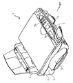
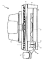
多機能装置1は、その後端部に位置する給紙装置2と、給紙装置2の下部前側に位置するインクジェット式のプリンタ3と、プリンタ3の上側に位置する、コピー機能とファクシミリ機能の為の読み取り装置4と、プリンタ3の前側に位置する排紙トレー5と、読み取り装置4の左側に位置する電話機6と、読み取り装置4の前端上面部に位置する操作パネル7とを備えている。操作パネル7は、LCD7aと、キーボード7bとを有している。
【0028】
また、多機能装置1は、排紙トレー5の左側に、第1外部メモリ11たるコンパクトフラッシュ(登録商標。以下CFと称す。)カードを挿入することができる第1スロット8、第2外部メモリ12たるメモリスティック(登録商標。以下MSと称す。)を挿入することができる第2スロット9、及び第3外部メモリ13たるスマートメディア(登録商標。以下SMと称す。)カードを挿入することができる第3スロット10を備えている。
【0029】
第1スロット8、第2スロット9、及び第3スロット10は、それぞれ、第1〜第3外部メモリ11〜13が挿入されると物理的にONとなるメモリ検出スイッチ(図示略)を備えており、メモリ検出スイッチがONとなると、その検出信号は、後述する制御部14に割り込みを行う。従って、第1〜第3スロット8〜10に外部メモリが挿入されると、制御部14はどのスロットに外部メモリが挿入されたかを認識するとともに、複数の外部メモリが対応するスロット挿入されると、その挿入の順序も記憶できるのである。
【0030】
更に、多機能装置1は、その内部に、各構成部を制御するための制御部14(図3参照)を備えている。
b)次に、制御部14について図3を用いて説明する。
制御装置14は、CPU15、ROM16、及びRAM17から成るマイクロコンピュータ18を有する。上記RAM17は、第1スロット8、第2スロット9、及び第3スロット10がそれぞれ備えるメモリ検出スイッチが発信する検出信号の順番を記憶する記憶手段としての機能を有する。
【0031】
また、制御装置14は、マイクロコンピュータ18とバス19を介して接続しているASIC20を備えている。このASIC20は、読み取り装置4と電気的に接続し、また、パネルI/F21を介して、操作パネル7のLCD7a及びキーボード7bに電気的に接続している。更に、ASIC20は着脱可能メモリI/F22を介して、第1スロット8、第2スロット9、及び第3スロット10と、それぞれ電気的に接続している。
【0032】
また、ASIC20はUSBI/F23を備えており、USBケーブルによりPCに接続することができる。加えて、ASIC20は、パラレルI/F24、及びNCU25を備えており、外部機器に対し、それぞれ、パラレルケーブル、回線により接続することができる。
【0033】
更に、制御装置14はモデム26を備えており、このモデム26とNCU25とを介して、外部機器と接続することができる。
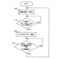
c)次に、多機能装置1のモード設定を図4のフローチャートを用いて説明する。このフローチャートは、多機能装置1の電源がONにされることによりスタートする。この多機能装置1は、電源がONにされると、PCとUSB接続されているかいないかに拘わらず、自動切替モードを設定する(ステップ100)。
【0034】
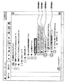
多機能装置1をPCにUSB接続すると、多機能装置1は、PCからデバイスチェックコマンドを受信するので、ストレージクラスであることを示すコマンドをPCに送る。
より具体的には、図5に示すように、多機能装置1はPCにおいて装置全体が「USB複合デバイス」として認識され、その下に更に複数の要素機能が認識される。例えば、USB印刷サポートが要素機能0、読取装置4(スキャナ)が要素機能1、ファクシミリ用モデムが要素機能2、大容量記憶装置デバイスが要素機能3として認識される。各要素機能は別々のクラスを持つことができ、要素機能3が「ストレージクラス」となる。
【0035】
多機能装置1は、後述するステップ110にてPCからGET_MAX_LUNコマンドを受信するまでは(初期状態では)、自動切替モードとなる。
以下、自動切替モードについて具体的に説明する。
多機能装置1の制御装置14は、第1スロット8、第2スロット9、第3スロット10のうち、1つのスロットのみにメディア(外部メモリ)が挿入されている場合は、そのスロットにのみ、LUN(Logical Unit Number)としてLUN0を割り振り、PCはそのスロットにのみアクセス可能となる。即ち、PCはLUN0の割り振られたスロットに挿入されているメディア(外部メモリ)にのみリード/ライトが可能になるのである。
【0036】
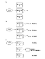
例えば、図6(a)に示すように、第2スロット9にのみメディア(第2外部メモリ12)が挿入され、第1スロット8及び第3スロット10にはメディア(各スロットに対応する外部メモリ)が挿入されていない場合は、第2スロット9にLUN0が割り振られ、PCは第2スロット9に挿入されている第2外部メモリ12にのみアクセス可能となる。
【0037】
また、第2スロット9に差し込んでいたメディア(第2外部メモリ12)を抜き取り、他の1つのスロット(例えば第1スロット8または第3スロット10)に新たにメディア(第1外部メモリ11または第3外部メモリ13)を挿入すると、その新たにメディアを挿入したスロットにLUN0が割り振られ、PCはそのスロットに挿入されている外部メモリにのみアクセス可能となる。
【0038】
尚、制御装置14は、上述した通り、スロットに設けられたメモリ検出スイッチからの割り込み信号により、メディア(外部メモリ)が挿入されているスロットを認識する。
また、多機能装置1の制御装置14は、第1スロット8、第2スロット9、第3スロット10のうち、2以上のスロットにメディアが挿入されている場合は、それらのスロットのうちで、メディア(外部メモリ)を最先に挿入したスロットにLUN0を割り振り、PCはそのスロットに挿入されている外部メモリにのみアクセス可能となる。
【0039】
例えば、図6(b)に示すように、第2スロット9、第1スロット8、第3スロット10の順番にメディア(外部メモリ)を挿入し、メディア(外部メモリ)が全て挿入したままとなっている場合は、メディア(外部メモリ)を最先に挿入した第2スロット9を最先メディア挿入スロットとしてLUN0を割り振り、PCとアクセス可能とする。従って、PCは、第1スロット8に挿入されている第1外部メモリ11と第3スロット10に挿入されている第3外部メモリ13にはアクセスできない。
【0040】
また、図6(c)に示すように、第2スロット9、第1スロット8、第3スロット10の順番でメディア(外部メモリ)を挿入したが、最先に挿入した第2スロット9からは既にメディア(第2外部メモリ12)を抜いている場合は、メディア(外部メモリ)が残っている第1スロット8及び第3スロット10のうちで、先にメディア(外部メモリ)を挿入した第1スロット8を最先メディア挿入スロットとしてLUN0を割り振り、PCとアクセス可能とする。この場合は、当然ながら、PCは第3スロット10に挿入されている第3外部メモリ13にアクセスできない。
【0041】
尚、各スロットにメディア(外部メモリ)を挿入した順番は、制御装置14のRAM17に記憶されている、各スロットのメディア検出スイッチが発する割り込み信号に基づいて決定される。
ステップ110では、多機能装置1がPCから、GET_MAX_LUNコマンド(多機能装置1の備えるスロット数を問い合わせるコマンド)を受信したか否かを判断する。
【0042】
このGET_MAX_LUNコマンドは、PCのOSが、PCにインストールされている、多機能装置1に対応するドライバに対し、多機能装置1の持つスロット数を問い合わせたとき、ドライバがマルチR/Wに対応したドライバである場合にのみ、ドライバから多機能装置1に対して送信されるコマンドである。つまり、GET_MAX_LUNコマンドは、PCがマルチR/Wに対応するドライバを備えていることを示すコマンドである。
【0043】
尚、PCにインストールされているドライバが、マルチR/Wに対応していないドライバである場合は、PCのOSからのスロット数の問い合わせに対し、ドライバはGET_MAX_LUNコマンドを発信することなく、スロット数が1であるとOSに返答する。
【0044】
GET_MAX_LUNコマンドを受信した場合はステップ120に進む。一方、GET_MAX_LUNコマンドを受信しない場合は、ステップ110を繰り返す。即ち、多機能装置1は自動切替モードが設定されたままの状態となる。
ステップ120では、多機能装置1の状態が自動切替モードからマルチドライブモードへと設定変更される。以下、マルチドライブモードについて具体的に説明する。
【0045】
GET_MAX_LUNコマンドを受信した多機能装置1は、本実施の形態におけるスロットの最大値である3を示す値「2」をPCに返信する。PCはスロット数を認識すると、LUNとしてLUN0を割り振られたスロット、LUNとしてLUN1を割り振られたスロット、及びLUNとしてLUN2を割り振られたスロットにそれぞれアクセスを要求する。尚、スロットが2つの場合、GET_MAX_LUNコマンドを受信した多機能装置1は値「1」をPCに返信することとなる。
【0046】
マルチドライブモードでは、予め、第1スロット8、第2スロット9、及び第3スロット10に、それぞれ、LUN0、LUN1、LUN2が固定値として割り振られているので、PCはLUN0が割り振られた第1スロット8、LUN1が割り振られた第2スロット、およびLUN2が割り振られた第3スロットにアクセス可能となる。
【0047】
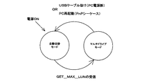
ステップ130では、多機能装置1とPCとを接続しているUSBケーブルが抜けること、PCの電源OFF、PC再起動のうちのいずれかがあったかを判断する。YESの場合はステップ100に進んで、多機能装置1には再び自動切替モードが設定される。一方、NOの場合はステップ130を繰り返す。即ち、多機能装置1はマルチドライブモードが設定されたままの状態となる。 図7は、多機能装置1の状態を示した図である。上記の説明からも明らかなように、多機能装置1の電源をONとすると、多機能装置1は自動切替モードとなる(ステップ100)。自動切替モードにあるときに、PCからGET_MAX_LUNコマンドを受信すると(ステップ110)、マルチドライブモードとなる(ステップ120)。また、マルチドライブモードにあるときに、USBケーブルの抜け、PCの電源OFF、PC再起動のいずれかがあると、自動切替モードに戻る(ステップ130)。
【0048】
c)次に、多機能装置1が実行するリード/ライト動作について説明する。
▲1▼まず、多機能装置1が自動切替モードにあるときのリード/ライト動作について説明する。
PCが多機能装置1からデータをリードするとき、図8(a)に示すように、PCは多機能装置1に対し、「LUN0を割り振られたスロットに挿入されている外部メモリをリード」のコマンドを送信する。それに対し、多機能装置1は、LUN0を割り振られたスロット(図8(a)では第2スロット9)に挿入されたメディア(第2外部メモリ12)からデータを読み出し、PCに送信する。最後に、多機能装置1は、PCに対し、OKまたはNGのステータスを送る。
【0049】
また、PCが多機能装置1にデータを書き込むときは、図8(b)に示すように、PCは多機能装置1に対し、「LUN0を割り振られたスロットに挿入されている外部メモリにライト」のコマンドを送信する。それに対し、多機能装置1は、LUN0を割り振られたスロット(図8(b)では第2スロット9)に挿入されたメディア(第2外部メモリ12)に、PCから送信されたデータを書き込む。最後に、多機能装置1は、PCに対し、OKまたはNGのステータスを送る。
【0050】
尚、LUN0を割り振られたスロットは、上述したように、第1スロット8、第2スロット9、及び第3スロット10のうち、1つのスロットのみにメディア(外部メモリ)が挿入されている場合は、そのスロットとなり、2以上のスロットにメディア(外部メモリ)が挿入されている場合は、それらのスロットのうちで、メディア(外部メモリ)を最先に挿入したスロットとなる。
【0051】
▲2▼次に、多機能装置1がマルチドライブモードにあるときのリード/ライト動作について説明する。
マルチドライブモードでは、第1スロット8、第2スロット9、及び第3スロット10には、それぞれ、LUN0、LUN1、LUN2が固定値として割り振られている。即ち、AドライブがFDD(フロッピー(登録商標)ディスクドライブ)に、CドライブがHDD(ハードディスクドライブ)にそれぞれ既に割り当てられている場合には、第1スロット8にDドライブが、第2スロット9にEドライブが、第3スロット10にFドライブがそれぞれ割り当てられるとともに、その順序は不変となる。つまり、マルチドライブモードにおいて、第1スロット8、第2スロット9、及び第3スロット10に割り当てられるドライブレターは、順番が固定される。
【0052】
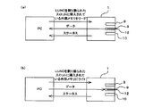
従って、図9(a)に示すように、PCが多機能装置1の第1スロット8に挿入されたメディア(第1外部メモリ11)からデータをリードするときは、PCから多機能装置1に対し、「LUN0を割り振られたスロットに挿入されている外部メモリをリード」のコマンドを送信し、第2スロット9に挿入されたメディア(第2外部メモリ12)からデータをリードするときは、「LUN1を割り振られたスロットに挿入されている外部メモリをリード」のコマンドを送信し、第3スロット10に挿入されたメディア(第3外部メモリ13)からデータをリードするときは、「LUN2を割り振られたスロットに挿入されている外部メモリをリード」のコマンドを送信する。これに対し、多機能装置1は、該当するスロットに挿入されたメディア(外部メモリ)からデータを読み出し、PCに送信する。最後に、多機能装置1は、PCに対し、OKまたはNGのステータスを送る。
【0053】
また、図9(b)に示すように、PCが多機能装置1の第1スロット8に挿入されたメディア(第1外部メモリ11)にデータをライトするときは、PCから多機能装置1に対し、「LUN0を割り振られたスロットに挿入されている外部メモリにライト」のコマンドを送信し、第2スロット9に挿入されたメディア(第2外部メモリ12)にデータをライトするときは、「LUN1を割り振られたスロットに挿入されている外部メモリにライト」のコマンドを送信し、第3スロット10に挿入されたメディア(第3外部メモリ13)にデータをライトするときは、「LUN2を割り振られたスロットに挿入されている外部メモリにライト」のコマンドを送信する。これに対し、多機能装置1は、該当するスロットに挿入されたメディア(外部メモリ)にデータをライトする。最後に、多機能装置1は、PCに対し、OKまたはNGのステータスを送る。
【0054】
d)次に、本実施例1の多機能装置1の奏する効果を説明する。
▲1▼本実施例1の多機能装置1は、電源をONにした後の初期状態では、自動切替モードとなる。この自動切替モードにおいて、PCは、第1スロット8、第2スロット9、及び第3スロット10のうち、メディア(外部メモリ)を挿入した単一のスロットにアクセス可能となる。
【0055】
つまり、本実施例1の多機能装置1では、PCがマルチR/Wに対応するドライバを備えていない場合でも、複数のスロットのうち、任意のスロットにメディアを挿入するだけで、そのままそのスロットがアクセス可能となる。
▲2▼本実施例1の多機能装置1では、自動切替モードにおいて、使用するスロットを切り替える際に、メディアを入れ換えるだけでよく、従来の周辺装置のように、アクセスするスロットを切り替えるためのスイッチ操作や、ケーブルを一旦抜く操作が必要ない。
【0056】
▲3▼本実施例1の多機能装置1は、PCがマルチR/Wに対応するドライバを備えている場合、マルチドライブモードとなることができる。このマルチドライブモードでは、PCは、複数のスロットにアクセス可能となる。
▲4▼本実施例1の多機能装置1では、マルチドライブモードにおいて、第1スロット8、第2スロット9、及び第3スロット10に割り振られているLUNの順序は一定であるので、各スロットのドライブレターの順序が切り替わることがなく、ユーザが混乱してしまうようなことがない。
【0057】
▲5▼本実施例1の多機能装置1は、第1スロット8、第2スロット9、及び第3スロット10にメディアを挿入した順番を、制御装置14のRAM17に記憶することができるので、自動切替モードにおいて、2以上のスロットにメディアが挿入されている場合は、そのRAM17に記憶した順番に基づき、メディアが挿入されている2以上のスロットのうち、メディアが最先に挿入されたスロットを決定することができる。そして、そのスロットにLUN0を割り振り、PCとアクセス可能なスロットとすることができる。
【0058】
このことにより、自動切替モードにおいて2以上のスロットにそれぞれメディアが挿入されている場合でも、PCがアクセス可能な単一のスロットを定めることができるので、多機能装置1の動作において混乱が生じることがない。
(実施例2)
本実施例2の多機能装置1の構成は、基本的には前記実施例1と同様である。但し、本実施例2の多機能装置1は、図10に示すように、内部メモリ27を備えている。尚、この実施例2では、独立した内部メモリ27がASIC20に接続されているように記載されているが、RAM17の一部領域が内部メモリ27として使用される構成であってもよい。
【0059】
本実施例2の多機能装置1では、前記実施例1と同様に、自動切替モード又はマルチドライブモードのうちのいずれかのモードとなる。
自動切替モードにおいて、第1スロット8、第2スロット9、及び第3スロット10のいずれにもメディアが挿入されていない場合は、内部メモリ27にLUN0が割り振られ、PCは内部メモリ27にアクセスが可能となる。
【0060】
一方、自動切替モードにおいて、第1スロット8、第2スロット9、及び第3スロット10のうちの1以上のスロットにメディアが挿入されている場合は、前記実施例1と同様に、第1スロット8、第2スロット9、及び第3スロット10のうちの1のスロットにLUN0が割り振られ、PCはそのスロットにアクセス可能となる。
【0061】
また、マルチドライブモードにおいて、PCは、LUNとして、LUN0、LUN1、LUN2、及びLUN3の4つのLUNを発行する。そして、第1スロット8、第2スロット9、第3スロット10、及び内部メモリ27に、それぞれ、LUN0、LUN1、LUN2、及びLUN3が固定順として割り振られる。その結果、PCは、第1スロット8、第2スロット9、第3スロット10、及び内部メモリ27にそれぞれアクセス可能となる。この場合、各スロット及び内部メモリ27に割り当てられるドライブレターは固定順となることは言うまでもない。
【0062】
本実施例2の多機能装置1は内部メモリ27を備えているので、マルチドライブモードにおいて、PCは、第1スロット8、第2スロット9、及び第3スロット10に加えて、内部メモリ27にもアクセス可能となる。
また、自動切替モードにおいて、3つのスロットのいずれにもメディアが挿入されていない場合のみ、PCは内部メモリ27にアクセス可能となる。
【0063】
(実施例3)
本実施例3の多機能装置1の構成及び動作は、基本的には前記実施例2と同様である。
ただし、本実施例3の多機能装置では、操作パネル7に、PCがアクセスする対象が、「第1スロット8、第2スロット9、及び第3スロット10のうちのいずれか」であるか、あるいは「内部メモリ27」であるかを選択するアクセス選択スイッチ(アクセス選択手段)7cをキーボード7bに備えており(図10参照)、また、自動切替モードにおける動作において、前記実施例2と異なる。以下具体的に説明する。尚、アクセス選択スイッチ(アクセス選択手段)7cはキーボード7b上に独立して設けられていても良いし、押下する度毎に各種機能を変更して表示するファンクションキーにおいて、その1つの機能として設けられていても良い。
【0064】
自動切替モードにおいて、第1スロット8、第2スロット9、及び第3スロット10のうちの1以上のスロットにメディア(外部メモリ)が挿入されている場合は、それら3つのスロットの中から、最先メディア挿入スロットを設定する。
つまり、第1スロット8、第2スロット9、及び第3スロット10のうちの1つのスロットのみにメディア(外部メモリ)が挿入されている場合は、そのスロットを最先メディア挿入スロットとする。
【0065】
また、第1スロット8、第2スロット9、及び第3スロット10のうちの2以上のスロットにメディア(外部メモリ)が挿入されている場合は、RAM17に記憶されている挿入の順番に基づき、メディア(外部メモリ)が最先に挿入されたスロットを最先メディア挿入スロットとする。
【0066】
アクセス選択スイッチにおいて、「第1スロット8、第2スロット9、及び第3スロット10のうちのいずれか」が選択されている場合は、PCは最先メディア挿入スロットにアクセス可能となる。
逆に、アクセス選択スイッチにおいて、「内部メモリ27」が選択されている場合は、PCは内部メモリ27にアクセス可能となる。
【0067】
尚、マルチドライブモードにおいては、前記実施例2と同様に、PCは第1スロット8、第2スロット9、第3スロット10、及び内部メモリ27にそれぞれアクセス可能となる。
本実施例3の多機能装置1は、自動切替モードにおいて、アクセス選択スイッチにより、第1スロット8、第2スロット9、及び第3スロット10のうちの最先メディア挿入スロットと、内部メモリ27とのいずれがPCに対しアクセス可能となるかを選択することができるという効果を奏する。
【0068】
尚、本発明は前記実施例になんら限定されるものではなく、本発明を逸脱しない範囲において種々の態様で実施しうることはいうまでもない。
・例えば、第1スロット8、第2スロット9、及び第3スロット10に設けられるメモリ検出スイッチは、導通スイッチであっても良い。この導通スイッチは、挿入されたメモリの端子と接続される装置側の端子のうち2つを、メモリ検出用の端子とするものである。例えば、そのメモリ検出用の端子を予めプルアップしておき、挿入したメモリの端子と接続するとGNDになるようにしておけば、メモリ検出用端子の電圧変化により、メモリの挿入を検知することができる。
【0069】
・また、多機能装置1が備えるスロットの数は3以外(例えば、2、4、5、6等)であってもよい。
・また、本発明の周辺装置は、多機能装置ではなく、単純なカードリーダに用いても良い。その場合、カードリーダをPCにUSB接続すると、図10に示すように、カードリーダ全体が「ストレージクラス」になる。
【図面の簡単な説明】
【図1】 実施例の多機能装置の構成を示す斜視図である。
【図2】 実施例の多機能装置の構成を示す正面図である。
【図3】 実施例の多機能装置の構成を示すブロック図である。
【図4】 実施例の多機能装置におけるモード設定処理を示すフローチャートである。
【図5】 実施例の多機能装置が有する要素機能の認識を示す説明図である。
【図6】 実施例の多機能装置におけるドライバ割り当てを示す説明図である。
【図7】 実施例の多機能装置におけるモード設定処理を示す説明図である。
【図8】 実施例の多機能装置が実行するリード/ライト処理を示す説明図である。
【図9】 実施例の多機能装置が実行するリード/ライト処理を示す説明図である。
【図10】 実施例の多機能装置の構成を示すブロック図である。
【図11】 PCがカードリーダを認識する状態を示す説明図である。
【符号の説明】
1・・・多機能装置
4・・・RAM
7・・・操作パネル
8・・・第1スロット
9・・・第2スロット
10・・・第3スロット
27・・・内部メモリ[0001]
BACKGROUND OF THE INVENTION
The present invention relates to a peripheral device that is connected to an information processing apparatus such as a personal computer (PC) and can read / write data from / to a removable medium such as a flash.
[0002]
[Prior art]
2. Description of the Related Art Conventionally, a peripheral device (media reader / writer) that includes a plurality of media slots (slots) and a priority switching switch that sets the priority of media slots is known (see Patent Document 1).
[0003]
When this media reader / writer is connected to a USB terminal of a personal computer (PC), necessary settings are automatically performed by the PLUG AND PLAY function. At this time, the firmware in the media reader / writer reports the slot priority order to the OS (Operating System) of the PC based on the setting of the priority selector switch.
[0004]
When an OS such as Windows (registered trademark) 98SE or Windows (registered trademark) 2000 is installed in the PC, driver software corresponding to a single slot card reader is installed as a standard. In this case, drive assignment is made only to the slot whose priority is set high in the priority changeover switch, and only the medium inserted in the slot can be read / written.
[0005]
On the other hand, when an OS such as Windows (registered trademark) Me or Windows (registered trademark) XP is installed in the PC, driver software corresponding to multi-R / W is installed as a standard. Multi-R / W refers to a mode in which drive assignment is made to each of a plurality of slots and each medium inserted in each slot can be read / written independently. In this case, priority is given. Drives are assigned to a plurality of slots according to the priority set by the changeover switch.
[0006]
For example, there are a slot for smart media (registered trademark, hereinafter referred to as SM) and a slot for compact flash (registered trademark, hereinafter referred to as CF), and priority is given to the slot for SM in the priority changeover switch. , A drive is already assigned to FDD (floppy (registered trademark) disk drive) and C drive is already assigned to HDD (hard disk drive), respectively, D drive is assigned to the SM slot, and CF drive E drive is assigned to the slot. On the other hand, if the priority slot is given priority to the CF slot, the D drive is assigned to the CF slot and the E drive is assigned to the SM slot.
[0007]
[Patent Literature]
JP 2002-32404 A
[0008]
[Problems to be Solved by the Invention]
In the above media reader / writer, as described above, when only the driver software corresponding to the single slot card reader is installed in the PC, the driver is assigned to only one slot set by the priority selector switch. However, in order to change the driver assignment, there is a problem that it is necessary to operate the PLUG AND PLAY function again after switching the priority changeover switch. Here, operating the PLUG AND PLAY function again specifically means restarting the OS of the PC or temporarily disconnecting the USB cable from the USB terminal of the PC and then inserting it again into the USB terminal of the PC. Means re-insertion / removal.
[0009]
In the above media reader / writer, when the driver software corresponding to the multi-R / W is installed in the PC, the drive assignment to each slot is switched according to the order set by the priority selector switch. According to the example, the SM slot is not always fixed to the D drive and the CF drive is not always fixed to the E drive, and there is a problem that the user may be confused.
[0010]
The present invention has been made in view of the above points, and when a PC does not have a multi-R / W compatible driver, the driver assignment can be changed without operating a switch or removing a cable once. An object of the present invention is to provide a peripheral device in which the drive letter of each slot is not switched and the user is not confused when the PC has a driver for multi-R / W. And
[0011]
[Means for Solving the Problems and Effects of the Invention]
(1) The invention of
A peripheral device that includes at least a plurality of slots into which a readable medium can be inserted and can be connected to an information processing device. In an initial state, the information processing device is a single unit in which a medium is inserted among the plurality of slots. When the automatic switching mode in which only one slot is accessible and a command indicating that a driver corresponding to multi-R / W is provided from the information processing apparatus, the information processing apparatus The gist of the peripheral device is a multi-drive mode in which the slot can be individually accessed.
[0012]
The peripheral device of the present invention is in the automatic switching mode in the initial state. In this automatic switching mode, the information processing apparatus can directly access a single slot into which a medium is inserted among slots of peripheral devices.
In other words, in the peripheral device of the present invention, even if the information processing device does not have a driver for multi-R / W, the slot can be accessed as it is simply by inserting media into any slot among the plurality of slots. It becomes possible.
[0013]
Furthermore, in the peripheral device of the present invention, when the slot to be used is switched in the automatic switching mode, there is no need to perform a switch operation for switching the slot to be accessed or an operation for temporarily disconnecting the cable unlike the conventional peripheral device.
On the other hand, the peripheral device of the present invention is in the multi-drive mode when the information processing apparatus includes a driver that supports multi-R / W. In this multi-drive mode, the information processing apparatus can simultaneously access a plurality of slots.
[0014]
In the peripheral device of the present invention, the order of LUN (Logical Unit Number) assigned to each slot in the multi-drive mode can be fixed, for example. In this case, the drive letter of each slot will not be switched and the user will not be confused.
[0015]
Note that the initial state refers to, for example, a state from when a peripheral device is powered on until a command indicating that a driver corresponding to multi-R / W is provided.
The multi-R / W refers to a state in which an information processing device (for example, a personal computer (PC)) can cope with two or more slots provided in a peripheral device individually (independently) and simultaneously.
[0016]
(2) The invention of claim 2
Storage means for storing the order in which media are inserted into the plurality of slots; in the automatic switching mode, when media are inserted into two or more of the plurality of slots, the storage means stores Based on the order, among the two or more slots into which media is inserted, the earliest media insertion slot that is the slot in which media is inserted first is set, and the information processing apparatus accesses the earliest media insertion slot. The gist of the peripheral device according to
[0017]
The peripheral device of the present invention includes storage means for storing the order in which media are inserted into a plurality of slots. When media are inserted into two or more slots in the automatic switching mode, the storage means stores the storage means. Based on the order, among the two or more slots in which the media are inserted, the slot in which the media is inserted first is defined as the earliest media insertion slot. The earliest media insertion slot is a slot that can be accessed by the information processing apparatus.
[0018]
As a result, in the present invention, a single slot that can be accessed by the information processing apparatus can be determined even when media is inserted in each of two or more slots in the automatic switching mode. There will be no confusion.
[0019]
(3) The invention of
In the multi-drive mode, the information processing apparatus can access the internal memory in addition to the plurality of slots, and in the automatic switching mode, media is inserted into any of the plurality of slots. The gist of the peripheral device according to
[0020]
Since the peripheral device of the present invention includes the internal memory, in the multi-drive mode, the information processing apparatus can access the internal memory in addition to the media inserted into the slot.
Further, in the automatic switching mode, the information processing apparatus can access the internal memory only when no media is inserted into any of the plurality of slots.
On the other hand, when a medium is inserted into any one of the plurality of slots, the information processing apparatus can access the slot.
[0021]
Examples of the internal memory include a hard disk, a RAM (Random Access Memory), a fixed (not a card or directly soldered) flash memory, and the like.
(4) The invention of
A peripheral device that includes at least a plurality of slots into which a readable medium can be inserted and an internal memory and can be connected to an information processing apparatus, and in the initial state, the medium is inserted into the plurality of slots. It is an automatic switching mode in which the information processing apparatus can access one of the single slot and the internal memory selected by the access selection means, and the information processing apparatus When a command indicating that a driver corresponding to W is provided is received, the information processing apparatus enters a multi-drive mode in which each slot and the internal memory can be individually accessed. The gist of the apparatus.
[0022]
In the automatic switching mode, the peripheral device according to the present invention provides an information processing device for one of the plurality of slots, that is, a single slot into which a medium is inserted and an internal memory selected by the access selection means. Is accessible.
On the other hand, in the multi-drive mode, the information processing apparatus can access the media inserted into the slot and the internal memory.
(5) The invention of
Storage means for storing the order in which media are inserted into the plurality of slots; in the automatic switching mode, when media are inserted into two or more of the plurality of slots, the storage means stores Based on the order, among the two or more slots into which media is inserted, a first media insertion slot that is a slot in which media is inserted first is set, and the first media insertion slot and the
[0023]
The peripheral device of the present invention includes storage means for storing the order in which media are inserted into a plurality of slots. When media are inserted into two or more slots in the automatic switching mode, the storage means stores the storage means. Based on the order, among the two or more slots in which the media are inserted, the slot in which the media is inserted first is defined as the earliest media insertion slot. Of the two, the earliest media insertion slot and the internal memory, one selected by the access selection means is made accessible to the information processing apparatus.
[0024]
As a result, in the present invention, even when media are inserted in two or more slots in the automatic switching mode, the information processing apparatus can determine one target to access, and the operation of the peripheral apparatus is confused. It does not occur.
(6) The invention of
6. The peripheral device according to
[0025]
In the present invention, in the multi-drive mode, the order of drive letters assigned to media inserted in a plurality of slots by the information processing apparatus is fixed, so that the user is not confused about the drive letters in each slot.
[0026]
DETAILED DESCRIPTION OF THE INVENTION
Examples (examples) of the peripheral device of the present invention will be described below. This embodiment is an example when the present invention is applied to a multi-function device having a printer function, a copy function, a scanner function, a facsimile function, a telephone function, and the like.
Example 1
a) First, the overall configuration of the
[0027]
The
[0028]
Further, the
[0029]
The
[0030]
Furthermore, the
b) Next, the
The
[0031]
In addition, the
[0032]
The
[0033]
Further, the
c) Next, mode setting of the
[0034]
When the
More specifically, as shown in FIG. 5, in the
[0035]
The
Hereinafter, the automatic switching mode will be specifically described.
When the medium (external memory) is inserted in only one of the
[0036]
For example, as shown in FIG. 6A, media (second external memory 12) is inserted only into the
[0037]
Further, the medium (second external memory 12) inserted into the
[0038]
As described above, the
In addition, the
[0039]
For example, as shown in FIG. 6B, media (external memory) are inserted in the order of the
[0040]
In addition, as shown in FIG. 6C, media (external memory) are inserted in the order of the
[0041]
The order in which media (external memory) are inserted into each slot is determined based on an interrupt signal that is stored in the
In
[0042]
This GET_MAX_LUN command is used when the OS of the PC inquires about the number of slots of the
[0043]
If the driver installed on the PC is a driver that does not support multi-R / W, the driver does not send a GET_MAX_LUN command to the slot number inquiry from the OS of the PC. If it is 1, it returns to the OS.
[0044]
If the GET_MAX_LUN command is received, the process proceeds to step 120. On the other hand, if the GET_MAX_LUN command is not received,
In
[0045]
Upon receiving the GET_MAX_LUN command, the
[0046]
In the multi-drive mode, LUN0, LUN1, and LUN2 are assigned as fixed values to the
[0047]
In
[0048]
c) Next, a read / write operation executed by the
(1) First, the read / write operation when the
When the PC reads data from the
[0049]
When the PC writes data to the
[0050]
Note that the slot to which LUN 0 is allocated is the case where the medium (external memory) is inserted in only one of the
[0051]
(2) Next, the read / write operation when the
In the multi-drive mode, LUN0, LUN1, and LUN2 are assigned as fixed values to the
[0052]
Accordingly, as shown in FIG. 9A, when the PC reads data from the medium (first external memory 11) inserted in the
[0053]
Further, as shown in FIG. 9B, when the PC writes data to the medium (first external memory 11) inserted into the
[0054]
d) Next, effects produced by the
(1) The
[0055]
That is, in the
(2) In the
[0056]
(3) The
(4) In the
[0057]
(5) Since the
[0058]
As a result, even when media are inserted in two or more slots in the automatic switching mode, a single slot accessible by the PC can be determined, so that confusion occurs in the operation of the
(Example 2)
The configuration of the
[0059]
In the
In the automatic switching mode, when no media is inserted in any of the
[0060]
On the other hand, in the automatic switching mode, when media is inserted in one or more of the
[0061]
In the multi-drive mode, the PC issues four LUNs, LUN0, LUN1, LUN2, and LUN3, as LUNs. Then, LUN0, LUN1, LUN2, and LUN3 are allocated to the
[0062]
Since the
In the automatic switching mode, the PC can access the
[0063]
(Example 3)
The configuration and operation of the
However, in the multi-function device of the third embodiment, whether the PC accesses the operation panel 7 is “any one of the
[0064]
In the automatic switching mode, when a medium (external memory) is inserted into one or more of the
That is, when a medium (external memory) is inserted into only one of the
[0065]
Further, when media (external memory) is inserted into two or more slots among the
[0066]
When “any one of the
Conversely, when “
[0067]
In the multi-drive mode, as in the second embodiment, the PC can access the
In the automatic switching mode, the
[0068]
Needless to say, the present invention is not limited to the above-described embodiments, and can be implemented in various modes without departing from the scope of the present invention.
For example, the memory detection switch provided in the
[0069]
The number of slots provided in the
The peripheral device of the present invention may be used for a simple card reader instead of a multi-function device. In this case, when the card reader is USB-connected to the PC, as shown in FIG. 10, the entire card reader becomes “storage class”.
[Brief description of the drawings]
FIG. 1 is a perspective view illustrating a configuration of a multi-function device according to an embodiment.
FIG. 2 is a front view showing the configuration of the multi-function device of the embodiment.
FIG. 3 is a block diagram illustrating a configuration of a multi-function device according to an embodiment.
FIG. 4 is a flowchart illustrating a mode setting process in the multi-function device according to the embodiment.
FIG. 5 is an explanatory diagram illustrating recognition of element functions included in the multi-function device according to the embodiment.
FIG. 6 is an explanatory diagram illustrating driver assignment in the multi-function device according to the embodiment.
FIG. 7 is an explanatory diagram illustrating a mode setting process in the multi-function device according to the embodiment.
FIG. 8 is an explanatory diagram illustrating read / write processing executed by the multi-function device according to the embodiment.
FIG. 9 is an explanatory diagram illustrating read / write processing executed by the multi-function device according to the embodiment.
FIG. 10 is a block diagram illustrating a configuration of a multi-function device according to an embodiment.
FIG. 11 is an explanatory diagram showing a state in which a PC recognizes a card reader.
[Explanation of symbols]
1 ... Multi-function device
4 ... RAM
7 ... Operation panel
8 ... 1st slot
9 ... 2nd slot
10 ... 3rd slot
27 ... Internal memory
Claims (6)
初期状態では、前記情報処理装置が前記複数のスロットのうち、メディアが挿入されている単一のスロットにのみアクセス可能な自動切替モードであるとともに、
前記情報処理装置から、マルチR/Wに対応するドライバを備えていることを示すコマンドを受信した場合は、前記情報処理装置が前記各スロットに対して個別にアクセス可能なマルチドライブモードとなることを特徴とする周辺装置。A peripheral device comprising at least a plurality of slots into which a readable medium can be inserted and connectable to an information processing device,
In an initial state, the information processing apparatus is in an automatic switching mode that can access only a single slot in which a medium is inserted among the plurality of slots.
When receiving a command indicating that a driver corresponding to multi-R / W is provided from the information processing apparatus, the information processing apparatus becomes a multi-drive mode in which each slot can be individually accessed. Peripheral device characterized by.
前記自動切替モードにおいて、前記複数のスロットのうちの2以上にメディアが挿入されている場合は、前記記憶手段に記憶された順番に基づき、メディアが挿入されている2以上のスロットのうち、メディアが最先に挿入されたスロットである最先メディア挿入スロットを設定し、該最先メディア挿入スロットを、情報処理装置がアクセス可能なスロットとすることを特徴とする請求項1記載の周辺装置。Storage means for storing the order in which media are inserted into the plurality of slots;
In the automatic switching mode, when media are inserted into two or more of the plurality of slots, the media among the two or more slots into which media are inserted is based on the order stored in the storage means. 2. The peripheral device according to claim 1, wherein a first media insertion slot which is a first inserted slot is set, and the first media insertion slot is a slot accessible by the information processing device.
前記マルチドライブモードでは、前記情報処理装置は、複数の前記スロットに加え、前記内部メモリにアクセス可能となり、
前記自動切替モードでは、前記複数のスロットのいずれにもメディアが挿入されていない場合にのみ、前記情報処理装置は、前記内部メモリにアクセス可能となることを特徴とする請求項1または2に記載の周辺装置。With internal memory,
In the multi-drive mode, the information processing apparatus can access the internal memory in addition to the plurality of slots.
3. The information processing apparatus according to claim 1, wherein in the automatic switching mode, the information processing apparatus can access the internal memory only when no media is inserted in any of the plurality of slots. Peripherals.
初期状態では、前記複数のスロットの中でメディアが挿入されている単一のスロットと、前記内部メモリとの2つのうち、アクセス選択手段により選択された1方に前記情報処理装置がアクセス可能となる自動切替モードであるとともに、
前記情報処理装置から、マルチR/Wに対応するドライバを備えていることを示すコマンドを受信した場合は、前記情報処理装置が前記各スロット及び前記内部メモリに対して個別にアクセス可能なマルチドライブモードとなることを特徴とする周辺装置。A peripheral device comprising at least a plurality of slots into which a readable medium can be inserted and an internal memory, and is connectable to an information processing device,
In an initial state, the information processing apparatus can access one of the plurality of slots, which is selected by the access selection means, from a single slot into which a medium is inserted and the internal memory. And automatic switching mode
A multi-drive capable of individually accessing the slots and the internal memory when the information processing apparatus receives a command indicating that a driver corresponding to multi-R / W is provided from the information processing apparatus Peripheral device characterized by being in mode.
前記自動切替モードにおいて、前記複数のスロットのうちの2以上にメディアが挿入されている場合は、前記記憶手段に記憶された順番に基づき、メディアが挿入されている2以上のスロットのうち、メディアが最先に挿入されたスロットである最先メディア挿入スロットを設定し、前記最先メディア挿入スロットと、前記内部メモリとの2つのうち、アクセス選択手段により選択された1方を、前記情報処理装置とアクセス可能とすることを特徴とする請求項4記載の周辺装置。Storage means for storing the order in which media are inserted into the plurality of slots;
In the automatic switching mode, when media are inserted into two or more of the plurality of slots, the media among the two or more slots into which media are inserted is based on the order stored in the storage means. Is set as the earliest slot inserted, and one of the two of the earliest media insertion slot and the internal memory selected by the access selection means is selected as the information processing slot. The peripheral device according to claim 4, wherein the peripheral device is accessible to the device.
Priority Applications (3)
| Application Number | Priority Date | Filing Date | Title |
|---|---|---|---|
| JP2003185697A JP4023402B2 (en) | 2003-06-27 | 2003-06-27 | Peripheral device |
| US10/876,715 US7526580B2 (en) | 2003-06-27 | 2004-06-28 | Peripheral device |
| US12/382,534 US7882287B2 (en) | 2003-06-27 | 2009-03-18 | Peripheral device |
Applications Claiming Priority (1)
| Application Number | Priority Date | Filing Date | Title |
|---|---|---|---|
| JP2003185697A JP4023402B2 (en) | 2003-06-27 | 2003-06-27 | Peripheral device |
Publications (2)
| Publication Number | Publication Date |
|---|---|
| JP2005018645A JP2005018645A (en) | 2005-01-20 |
| JP4023402B2 true JP4023402B2 (en) | 2007-12-19 |
Family
ID=34185066
Family Applications (1)
| Application Number | Title | Priority Date | Filing Date |
|---|---|---|---|
| JP2003185697A Expired - Fee Related JP4023402B2 (en) | 2003-06-27 | 2003-06-27 | Peripheral device |
Country Status (1)
| Country | Link |
|---|---|
| JP (1) | JP4023402B2 (en) |
Families Citing this family (10)
| Publication number | Priority date | Publication date | Assignee | Title |
|---|---|---|---|---|
| JP2006293760A (en) | 2005-04-12 | 2006-10-26 | Toshiba Corp | Information processor |
| JP4622770B2 (en) * | 2005-09-20 | 2011-02-02 | ブラザー工業株式会社 | COMMUNICATION SYSTEM, INFORMATION PROCESSING DEVICE, PERIPHERAL DEVICE, AND COMMUNICATION METHOD |
| US7869074B2 (en) | 2005-09-20 | 2011-01-11 | Brother Kogyo Kabushiki Kaisha | Communication system, information processing device, peripheral device and communication method |
| US7797398B2 (en) | 2005-09-20 | 2010-09-14 | Brother Kogyo Kabushiki Kaisha | Communication system, and peripheral device having trigger generating device and computer program product that monitors whether a trigger has been generated |
| JP4544188B2 (en) * | 2006-03-30 | 2010-09-15 | ブラザー工業株式会社 | Drive configuration program |
| US7941579B2 (en) | 2006-06-30 | 2011-05-10 | Brother Kogyo Kabushiki Kaisha | Communication system for authenticating authority of host device for accessing storage medium set to periphery device |
| JP2008090491A (en) | 2006-09-29 | 2008-04-17 | Brother Ind Ltd | Ftp communication system |
| JP4333765B2 (en) | 2007-03-28 | 2009-09-16 | ブラザー工業株式会社 | Device control system |
| JP2009232097A (en) | 2008-03-21 | 2009-10-08 | Brother Ind Ltd | Multi-functional peripheral device and network system |
| JP7151498B2 (en) * | 2019-01-18 | 2022-10-12 | ブラザー工業株式会社 | control board |
-
2003
- 2003-06-27 JP JP2003185697A patent/JP4023402B2/en not_active Expired - Fee Related
Also Published As
| Publication number | Publication date |
|---|---|
| JP2005018645A (en) | 2005-01-20 |
Similar Documents
| Publication | Publication Date | Title |
|---|---|---|
| US7882287B2 (en) | Peripheral device | |
| TW386207B (en) | Memory card interface apparatus | |
| US7111121B2 (en) | USB storage device and program | |
| US20090244624A1 (en) | Printer and its controlling method | |
| EP1491982B1 (en) | USB storage device and control device | |
| JP4023402B2 (en) | Peripheral device | |
| TW581704B (en) | Entertainment device, information processing device, and mobile recording device | |
| WO2008065886A1 (en) | Information processing apparatus and control method for information processing apparatus | |
| US20060026350A1 (en) | Method and apparatus to automatically switch memory cards in a multi-functional device, and method of configuring a removable disc driver | |
| JP3914949B2 (en) | USB storage device, control device thereof, and program for causing control device to execute | |
| JP4062227B2 (en) | Peripheral device and image forming apparatus | |
| JP2007001090A (en) | Data backup system for image forming apparatus, image forming apparatus, and data backup method | |
| EP1749268B1 (en) | Method for managing the plug-in or removal of a memory card into or from a card reader and apparatus for use in said method | |
| JP2006079634A5 (en) | ||
| JP3699717B2 (en) | USB storage device and control device thereof | |
| EP1770538B1 (en) | SCSI communication system, information processing device, peripheral device and communication method | |
| JP2001143053A (en) | Electronic filing system | |
| KR20090010418A (en) | Method and apparatus for installing printer driver of image forming apparatus in printing environment which used universal printer driver | |
| JP2006181735A (en) | Data outputting apparatus and information processing apparatus | |
| JP2004302870A (en) | Write-protect method for media reader/writer | |
| JP4759212B2 (en) | Information recording / reproducing device | |
| JP2006082256A (en) | Printing system and information processor | |
| JP4242798B2 (en) | USB storage device and control device thereof | |
| US20190235783A1 (en) | Information processing apparatus and control method of information processing apparatus | |
| JP2000132488A (en) | Information processing system |
Legal Events
| Date | Code | Title | Description |
|---|---|---|---|
| A621 | Written request for application examination |
Free format text: JAPANESE INTERMEDIATE CODE: A621 Effective date: 20050225 |
|
| A977 | Report on retrieval |
Free format text: JAPANESE INTERMEDIATE CODE: A971007 Effective date: 20070822 |
|
| TRDD | Decision of grant or rejection written | ||
| A01 | Written decision to grant a patent or to grant a registration (utility model) |
Free format text: JAPANESE INTERMEDIATE CODE: A01 Effective date: 20070911 |
|
| A61 | First payment of annual fees (during grant procedure) |
Free format text: JAPANESE INTERMEDIATE CODE: A61 Effective date: 20070924 |
|
| R150 | Certificate of patent or registration of utility model |
Ref document number: 4023402 Country of ref document: JP Free format text: JAPANESE INTERMEDIATE CODE: R150 Free format text: JAPANESE INTERMEDIATE CODE: R150 |
|
| FPAY | Renewal fee payment (event date is renewal date of database) |
Free format text: PAYMENT UNTIL: 20101012 Year of fee payment: 3 |
|
| FPAY | Renewal fee payment (event date is renewal date of database) |
Free format text: PAYMENT UNTIL: 20101012 Year of fee payment: 3 |
|
| FPAY | Renewal fee payment (event date is renewal date of database) |
Free format text: PAYMENT UNTIL: 20111012 Year of fee payment: 4 |
|
| FPAY | Renewal fee payment (event date is renewal date of database) |
Free format text: PAYMENT UNTIL: 20111012 Year of fee payment: 4 |
|
| FPAY | Renewal fee payment (event date is renewal date of database) |
Free format text: PAYMENT UNTIL: 20121012 Year of fee payment: 5 |
|
| FPAY | Renewal fee payment (event date is renewal date of database) |
Free format text: PAYMENT UNTIL: 20131012 Year of fee payment: 6 |
|
| LAPS | Cancellation because of no payment of annual fees |