JP4006949B2 - Image processing system, image processing apparatus, and imaging apparatus - Google Patents
Image processing system, image processing apparatus, and imaging apparatus Download PDFInfo
- Publication number
- JP4006949B2 JP4006949B2 JP2001039272A JP2001039272A JP4006949B2 JP 4006949 B2 JP4006949 B2 JP 4006949B2 JP 2001039272 A JP2001039272 A JP 2001039272A JP 2001039272 A JP2001039272 A JP 2001039272A JP 4006949 B2 JP4006949 B2 JP 4006949B2
- Authority
- JP
- Japan
- Prior art keywords
- player
- movement
- hand
- image
- difference
- Prior art date
- Legal status (The legal status is an assumption and is not a legal conclusion. Google has not performed a legal analysis and makes no representation as to the accuracy of the status listed.)
- Expired - Lifetime
Links
Images


Classifications
-
- A—HUMAN NECESSITIES
- A63—SPORTS; GAMES; AMUSEMENTS
- A63F—CARD, BOARD, OR ROULETTE GAMES; INDOOR GAMES USING SMALL MOVING PLAYING BODIES; VIDEO GAMES; GAMES NOT OTHERWISE PROVIDED FOR
- A63F2300/00—Features of games using an electronically generated display having two or more dimensions, e.g. on a television screen, showing representations related to the game
- A63F2300/10—Features of games using an electronically generated display having two or more dimensions, e.g. on a television screen, showing representations related to the game characterized by input arrangements for converting player-generated signals into game device control signals
- A63F2300/1087—Features of games using an electronically generated display having two or more dimensions, e.g. on a television screen, showing representations related to the game characterized by input arrangements for converting player-generated signals into game device control signals comprising photodetecting means, e.g. a camera
- A63F2300/1093—Features of games using an electronically generated display having two or more dimensions, e.g. on a television screen, showing representations related to the game characterized by input arrangements for converting player-generated signals into game device control signals comprising photodetecting means, e.g. a camera using visible light
-
- A—HUMAN NECESSITIES
- A63—SPORTS; GAMES; AMUSEMENTS
- A63F—CARD, BOARD, OR ROULETTE GAMES; INDOOR GAMES USING SMALL MOVING PLAYING BODIES; VIDEO GAMES; GAMES NOT OTHERWISE PROVIDED FOR
- A63F2300/00—Features of games using an electronically generated display having two or more dimensions, e.g. on a television screen, showing representations related to the game
- A63F2300/60—Methods for processing data by generating or executing the game program
- A63F2300/66—Methods for processing data by generating or executing the game program for rendering three dimensional images
- A63F2300/6692—Methods for processing data by generating or executing the game program for rendering three dimensional images using special effects, generally involving post-processing, e.g. blooming
Landscapes
- User Interface Of Digital Computer (AREA)
- Image Analysis (AREA)
- Processing Or Creating Images (AREA)
- Image Processing (AREA)
- Closed-Circuit Television Systems (AREA)
- Studio Devices (AREA)
Description
【0001】
【発明の属する技術分野】
本発明は、遊戯者の画像を撮像して、その撮像画像を利用する画像処理システムに関する。
【0002】
【従来の技術】
ゲームセンタ等に設置されるアーケードゲーム装置や家庭用のビデオゲーム装置には、近年多種多様な興趣溢れるゲームが開発され、娯楽として人気が非常に高いものがある。
【0003】
従来のゲーム装置に、遊戯者を撮像してその撮像画像を利用したものが知られている。例えば、プリントクラブのように、遊戯者の像を取り込んで背景と組み合わせて印刷して遊戯者に提供するものや、遊戯者の顔画像を取り込んで、それをゲームキャラクタの顔に貼り付けて独自なキャラクタを創出したりするものがある。
【0004】
また、従来のゲーム装置には、コントローラのような位置指示手段により表示画面上の位置を指示して、その指示位置に表示された色情報に基づいて、ゲームを制御したり、特定の移動体を発生したりするものがある。
【0005】
【発明が解決しようとする課題】
しかしながら、従来のゲーム装置では、遊戯者を撮像しても、その撮像画像の全部又は一部を画像として利用するにとどまっており、その撮像画像から特定の情報を得るものではなかった。
【0006】
本発明の目的は、遊戯者等の撮像画像から特定の情報を得て、その情報に基づいて画像表示を制御する画像処理システムを提供することにある。
【0007】
本発明の他の目的は、遊戯者の指示に関連して移動体をスムーズかつユニークに動かすことができる画像処理システムを提供することにある。
【0008】
本発明の更に他の目的は、遊戯者から操作入力をスムーズに行うことができる画像処理システムを提供することにある。
【0009】
【課題を解決するための手段】
本発明による画像処理システムは、遊戯者の画像を撮像する撮像手段と、前記撮像手段により撮像した画像データを複数フレーム分記憶する記憶手段と、前記記憶手段に記憶された画像データを表示画面上に順次表示する画像表示手段と、現在表示されている画像データと過去に表示された画像データとを比較して差分を得る差分算出手段とを有し、前記差分算出手段により算出された差分に基づいて、前記表示画面上に表示する移動体の挙動を決定することを特徴とする。
【0010】
また、本発明による画像処理システムは、遊戯者の画像を撮像する撮像手段と、前記撮像手段により撮像した画像データを複数フレーム分記憶する記憶手段と、前記記憶手段に記憶された画像データを表示画面上に順次表示する画像表示手段と、前記表示画面内の予め定められた領域における、現在表示されている画像データと過去に表示された画像データとを比較して所定の色成分の差分を得る差分算出手段とを有し、前記差分算出手段により算出された所定の色成分の差分が所定値以上であった場合に、前記遊戯者からの所定の操作入力があったと判断することを特徴とする。
【0011】
【発明の実施の形態】
[第1実施形態]
本発明の第1実施形態によるビデオゲーム装置について図1乃至図4を用いて説明する。図1は本実施形態のビデオゲーム装置の機能を示すブロック図であり、図2は本実施形態のビデオゲーム装置の遊戯方法の第1の具体例を示す説明図であり、図3は本実施形態のビデオゲーム装置の遊戯方法の第2の具体例を示す説明図であり、図4は本実施形態のビデオゲーム装置の遊戯方法の第3の具体例を示す説明図である。
【0012】
ゲーム装置200には、図1に示すように、ゲームプログラムの実行やシステム全体を制御するCPU202と、CPU202が処理を行うのに必要なプログラムやデータを格納するバッファメモリとして利用されるシステムメモリ(RAM)204とがバスラインにより共通接続され、バスアービタ210に接続されている。
【0013】
更に、ゲームプログラムやデータが格納されたプログラムデータ記憶装置又は記憶媒体206として、ゲーム用記録媒体であるCD−ROMを駆動するCD−ROMドライブと、ゲーム装置200を起動するためのプログラムやデータが格納されているBOOTROM208とがバスラインを介してバスアービタ210に接続されている。
【0014】
また、バスアービタ210を介して、描画ライブラリによって生成された描画コマンドに従ってレンダリングを行うレンダリングプロセッサ212と、そのレンダリングプロセッサ212により描画された画像信号が記録されるグラフィックメモリ214とが接続されている。グラフィックメモリ214に記録された画像データは、ビデオDAC(図示せず)によりデジタル信号からアナログ信号に変換され、ディスプレイモニタ216に表示される。
【0015】
また、バスアービタ210を介して、音声データを生成するオーディオプロセッサ218と、その生成した音声データを記録するオーディオメモリ220とが接続されている。オーディオメモリ220に記録された音声データは、オーディオDAC(図示せず)によりデジタル信号からアナログ信号に変換され、スピーカ222から音声出力される。
【0016】
また、バスアービタ210はインターフェースとしての機能も有し、モデム224を介して外部の通信回線と接続される。ゲーム装置200はモデム224を介して他のゲーム装置等との通信が可能となる。
【0017】
また、バスアービタ210にはゲーム装置200を操作するためのコントローラ226が接続される。コントローラ226には、例えば、メモリカード等により構成されたバックアップメモリ228が装着されている。
【0018】
また、遊戯者の画像や音声を入力するために、バスアービタ210には画像を撮影するための電子カメラ232が接続され、コントローラ226には音声を入力するためのマイク230が接続されている。
【0019】
本実施形態のビデオゲーム装置を用いた遊戯方法の第1の具体例を図2を用いて説明する。
【0020】
本具体例では、ゲーム装置200に接続された電子カメラ232をディスプレイモニタ216上に置き、遊戯者300は電子カメラ232の前に立って後述する様々な指示を行う。電子カメラ232により撮像された画像はディスプレイモニタ216に表示される。遊戯者300は自分の撮像画像を見ながら様々な動作を行う。
【0021】
本具体例では、電子カメラ232によりYUV方式で撮像する。YUV方式は、家庭用テレビ等であつかうデータフォーマットであって、輝度(Y)と、赤との色差(U)と、青との色差(V)との3つの情報で色を表現する方式である。例えば、Y成分だけで、画像を表示すると白黒画像となる。YUV方式で撮像された画像は圧縮されてシステムメモリ204に格納される。なお、ディスプレイの種類によってはRGB信号へ変換が必要である。
【0022】
遊戯者300は、ディスプレイ216に表示される画像を見ながら電子カメラ232に向かって様々な動作を行うので、違和感なく操作できるように、撮像された画像300′を反転して表示する。すなわち、図2に示すように、遊戯者300が左手を上げた場合には、ディスプレイ216に表示される遊戯者の像300′では右手が上がるように表示する。
【0023】
本具体例では、電子カメラ232により撮像された画像データは圧縮されてシステムメモリ204に順次記憶される。システムメモリ204に、現在表示されている画像データに加えて過去に表示された画像データとが記憶される。過去に表示された画像データとしては、例えば、現在表示されている画像データの1フレーム前の画像データであってもよいし、現在表示されている画像データの所定フレーム前の画像データであってもよい。また、過去の画像データは1フレーム分の画像データであってもよいし、2以上のフレーム分の画像データであってもよい。
【0024】
本具体例では、システムメモリ204に記憶された現在の画像データと過去の画像データとの差分を算出し、その差分データに基づいて様々な処理を行う。現在の画像データと過去の画像データについて、ピクセル毎にYUV方式における各色成分(輝度、赤、青)の差分を算出する。
【0025】
本具体例では、各色成分の差分データに基づいて移動体の制御を行う。これにより背景等の動かない画像データに影響しないようにする。例えば、人間の手には赤み成分が多いので、遊戯者300が手を動かすと、その動かした領域のみに大きな赤み成分の差分値が現れ、他の領域での赤み成分の差分値はほぼゼロとなる。
【0026】
そこで、本実施形態では、赤み成分の差分値が所定値以上になると、例えば、蛙を模した移動体302を自動的に発生する。赤み成分の差分値が所定値以上の領域に無数の泡303を表示し、発生した移動体302は赤み成分の差分値が最大値の部分に追随して移動する。これにより遊戯者が手を動かすと、その領域全体に泡303が現れ、移動体303の蛙が泡303の中を泳ぐように追随して表示される。なお、赤み成分の差分値が所定値以上の領域に泡以外のもの、例えば、ハートマークや炎等を表示して特殊な効果を出すようにしてもよい。
【0027】
移動体302の発生、追随、消滅のアルゴリズムは、後述する本発明の第2実施形態における虫移動描画処理(図14乃至図24)のアルゴリズムと基本的に同じである。第2実施形態の虫移動描画処理では画像の色データそのものを用いて虫等の移動体の描画制御を行ったが、本実施形態では色成分の差分データを用いている点が異なる。
【0028】
移動体302を、赤み成分の差分データにより発生し、差分データの最大値のピクセルに追随するように描画すると、人間の手には赤み成分が多いので、遊戯者300が手を振るとそれに自然に移動体302が追随するように表示され、あたかも移動体302が遊戯者300の手を追いかけているように表示される。
【0029】
本具体例では、図2に示すように、撮像画像の青み成分の差分データにより発生、追随、消滅する他の移動体304を表示するようにしている。その他に、差分データにより挙動が決定される他の移動体を表示するようにしてもよい。例えば、現在の画像データと過去の画像データとの各色成分(輝度、赤、青)の差分データの合計値や、最大値、平均値、分布等の状態に基づいて移動体を発生、追随、消滅等の処理を行うようにしてもよい。
【0030】
また、移動体302に対する処理のアルゴリズムに、後述する本発明の第2実施形態における動物移動描画処理(図27乃至図36)のアルゴリズムを利用してもよい。画像データの色成分の差分データに対して、このアルゴリズムを適用し、ディスプレイモニタ216に移動体等を発生させ、移動体の周囲の差分データに基づいて移動体の絵を切り換えたり、ときどき停止したりしてもよい。
【0031】
このように本具体例によれば、人間の手の赤み成分を利用しているので、特別な装置を衣服や手に装着する必要がなく、より簡便なキャラクタ入力手段として用いることができ、遊戯者の指示に関連して移動体をスムーズかつユニークに動かすことができる。
【0032】
また、人間の手の赤み成分を利用する代わりに、特殊な道具を装着してもよい。例えば、手の代わりに先端が赤色の指揮棒を手に持って操作して、本具体例のような効果的な表示をしてもよい。また、右手に赤色の手袋、左手に青色の手袋をつけ、赤み成分により発生する移動体302と青み成分により発生する移動体304を右手の動きと左手の動きにより自在に操るようにしてもよい。更に、人間の手そのものを用いる方法と、特殊な道具を用いる方法とを適宜組み合わせるようにしてもよい。
【0033】
本実施形態のビデオゲーム装置を用いた遊戯方法の第2の具体例を図3を用いて説明する。
【0034】
本具体例も、第1の具体例と同様に、電子カメラ232により撮像された画像データは圧縮されてシステムメモリ204に順次記憶される。システムメモリ204に記憶された現在の画像データと過去の画像データとの差分を算出し、その差分データに基づいて処理を行う。
【0035】
本具体例では、ディスプレイモニタ216上に特定の検出領域312を設定し、その特定の検出領域312における差分データの値により遊戯者310の操作情報を検出する。例えば、遊戯者310に赤色の指示棒314を持たせ、その指示棒314の像314′が検出領域312内を移動したか否かにより操作情報を検出する。指示棒314の像314′が検出領域312内を移動すると、検出領域312内における赤み成分の差分値が所定値以上になる。これにより遊戯者310の操作を検出する。
【0036】
遊戯者310は、ディスプレイモニタ216に表示された像310′、314′を見ながら、ゲーム装置200に所定の操作指示を行いたい場合には、指示棒314の像314′が検出領域312内を横切るように操作すればよい。遊戯者310は自由なスタイルで自由に操作を行うことができる。
【0037】
なお、遊戯者310に位置がわかるように検出領域312に予め特定の色をつけて他の領域と区別してもよい。遊戯者310が検出領域312を知って確実に操作することができる。逆に、検出領域312に特別な色をつけないようにしてもよい。遊戯者310に検出領域312の位置を捜すことをゲームに取り入れることができる。
【0038】
このように本具体例によれば、単に指示棒等の操作手段を移動するだけでよいので、より簡便な操作入力手段として用いることができ、遊戯者から操作入力をスムーズに行うことができる。
【0039】
本実施形態のビデオゲーム装置を用いた遊戯方法の第3の具体例を図4を用いて説明する。
【0040】
本具体例も、第1の具体例と同様に、電子カメラ232により撮像された画像データは圧縮されてシステムメモリ204に順次記憶される。システムメモリ204に記憶された現在の画像データと過去の画像データとの差分を算出し、その差分データに基づいて処理を行う。
【0041】
本具体例では、遊戯者の意図的な操作を検出してゲーム開始に対して起動するものである。遊戯者が電子カメラ232の前で手を振ったときに、その手の動きの移動距離を累積して、その累積距離が所定の設定値を超えた場合に入力されたと判断する。この操作入力により、ゲームを開始したり、特定のキャラクタを出現したり、画面を切り換えたり等の様々な制御を行う。
【0042】
初期画面においては、図4(a)に示すように、黒い画面の中に円い窓320が表示されている。この窓320が手の動きを検出する窓となる。遊戯者が電子カメラ232の前に手をかざして動かすと、赤み成分の差分データから手が動いた位置を検出し、その動いた位置に窓320を移動する。その結果、図4(b)に示すように、丸い窓320内に遊戯者の手322が写った状態が表示される。
【0043】
遊戯者が手322を動かすと、図4(c)、(d)に示すように、遊戯者の手322の動きに追随して丸い窓320が移動する。ゲーム装置200は円い窓320の移動距離を演算して、その移動距離を累積していく。遊戯者による操作の開始時からの累積距離が所定値に達した場合にゲーム開始操作が入力されたと判断し、図26(e)に示すように、ゲームを開始する。
【0044】
遊戯者による意図しない動きによりゲーム開始と判断されることを防止するために様々な工夫をしている。例えば、手の動きの速度を考慮して移動距離を累積する。手の動きの速さが所定値以上の場合には移動距離をそのまま累積するが、手の動きが所定値以下の場合には実際の移動距離から所定距離を減算したものを累積する。また、手の動きが検出されてから所定時間が経過しても累積距離がゲーム開始のための所定値に達しない場合には累積距離をリセットする。
【0045】
上記実施形態では丸い窓320の中に遊戯者の手の像322を組み込んで表示したが、実際の手の画像を用いることなく模式的なマークにより表示してもよい。すなわち、遊戯者の手の動きが検出されたら、単なる円い窓のマークから円い窓内に手が描かれたマークに移動体の画像を変更するようにしてもよい。なお、遊戯者の手を振る操作をゲーム開始以外の他の操作情報としてもよい。
【0046】
このように本具体例によれば、遊戯者が電子カメラの前で手を振ることによりゲームを開始する等の操作指示を行うことができ、遊戯者から操作入力をスムーズに行うことができる。
【0047】
[第2実施形態]
本発明の第2実施形態によるビデオゲーム装置について図5乃至図8を用いて説明する。図5は本実施形態のビデオゲーム装置の外観を示す斜視図であり、図6は本実施形態のビデオゲーム装置のソフトウエアカートリッジであり、図7は本実施形態のビデオゲーム装置のハードウエアを示すブロック図であり、図8は本実施形態のビデオゲーム装置の機能を示すブロック図である。
【0048】
(ゲーム装置本体)
本実施形態のビデオゲーム装置は、折り畳み式のゲーム装置本体10に絵本タイプのソフトウエアカートリッジ12を装着するものである。図5に示すように、ゲーム装置本体10の底蓋14から上蓋16を外して開き、その内側のカートリッジスロット18にソフトウエアカートリッジ12を差し込む。
【0049】
後述するように、本実施形態では、第1実施形態と同様に電子カメラ55を設けることも可能である。電子カメラ55は、例えば、図3に示すようにモニタ90の上に置かれ、ソフトウエアカートリッジ12のコネクタ(図示せず)に接続される。
【0050】
ゲーム装置本体10の底蓋14内側には、左側に方向ボタン20と実行ボタン22が設けられ、中央にお絵描きタブレット24が設けられ、右側にタッチペンホルダ26が設けられている。
【0051】
方向ボタン20及び実行ボタン22は、遊戯者が操作するものであって、方向ボタン20により上下左右の4方向を指示し、実行ボタン22により実行指示を与える。タッチペンホルダ26は、タッチペン28を保持する。タッチペン28は、お絵描きタブレット24に触って、絵本ソフトを操作するために用いられる。タッチペン28の先端にはペンボタン28aが設けられている。遊戯者はペンボタン28aを押すことにより指示を与える。
【0052】
お絵描きタブレット24は、電磁誘導方式によりタッチペン28が近接している位置を検出する。お絵描きタブレット24から発せられる電磁信号をタッチペン28により受信することにより位置を検出する。遊戯者はペンボタン28aを押すことにより、その位置に基づいた指示を与える。
【0053】
ゲーム装置本体10の上蓋16内側には、中央に絵本タイプのソフトウエアカートリッジ12が装着される絵本タブレット32が設けられている。この絵本タブレット32は、お絵描きタブレット24と同様の電磁誘導方式により、タッチペン28が近接した位置を検出する。
【0054】
絵本タブレット32の左側下部には電源をオンオフするためのパワースイッチ34が設けられている。絵本タブレット32の右側下部にはソフトウエアカートリッジ12が差し込まれるカートリッジスロット18が設けられている。装着されたソフトウエアカートリッジ12は、リジェクトボタン36を押すことによりカートリッジスロット18から取り外すことができる。
【0055】
絵本タブレット32内の上部右側にはページセンサ38が設けられている。ソフトウエアカートリッジ12の絵本のどのページ42が開かれているかをページセンサ38により検出する。絵本の各ページ42の右上部には切り込みが形成され、ページ順に切り込み幅を広くしている。このようにすることにより、開かれているページに応じて遮蔽するセンサ数が異なり、現在開かれているページを検出することができる。
【0056】
ソフトウエアカートリッジ12は、図5に示すように、左縁部の綴じリング40により複数ページ42を綴じた絵本のような基本形態をしている。各ページ42にはゲームプログラムに対応した絵が描かれている。
【0057】
(ソフトウエアカートリッジ)
ソフトウエアカートリッジ12を図6を用いて説明する。図6は絵本の各ページ42が閉じられている状態のソフトウエアカートリッジ12の平面図である。
【0058】
ソフトウエアカートリッジ12は、上部が、絵本を載置する絵本載置部46となっており、下部が、回路基板48を内部に収納する基板収納部50となっている。
【0059】
絵本載置部46の左縁部には綴じリング40が設けられ、絵本の各ページ42が閉じられている。本実施形態では5頁のページ42が閉じられており、各ページ42の右縁部にはインデックスがずらして形成されている。絵本載置部46の右上部には、絵本タブレット32のページセンサ38の位置に対応した6個のセンサ用穴52が開けられている。
【0060】
基板収納部50には内部に回路基板48が収納されている。回路基板48には、ゲーム装置本体10に接続するためのコネクタ49が形成され、ゲームプログラムを格納したプログラムROM54が搭載されている。
【0061】
(ハードウエア)
次に、本実施形態のビデオゲーム装置のハードウエアの構成を図7を用いて説明する。
【0062】
ゲーム装置本体10について説明する。MPU60はビデオゲーム装置全体を制御する。RAM62はMPU60のワーク用メモリである。ビデオディスプレイプロセッサ(VDP)64は背景やキャラクタ等の描画処理を制御する。映像情報はビデオRAM66に書き込まれる。ビデオディスプレイプロセッサ64からの映像信号は映像端子70からモニタ90に出力される。
【0063】
なお、電子カメラ55を利用する場合には、ビデオプロセッサ(VDP)64は電子カメラ55で撮像した映像情報を、背景やキャラクタ等のゲーム画像と合成して描画情報を制御する。その映像情報をビデオRAM66に書き込み、ビデオプロセッサ(VDP)64により、映像端子70からモニタ90に出力する。電子カメラ55で撮像した映像情報を画像認識することにより操作入力することもできる。
【0064】
音声合成LSI(ADPCM)72はキャラクタがしゃべる言葉等のあらゆる音声を合成する。ゲームに応じた音声を合成して発音する。ビデオディスプレイプロセッサ64からの音声信号と音声合成LSI72からの音声信号を混合して、音声端子76を介してモニタ90に出力する。
【0065】
コントローラ78は、方向ボタン20、実行ボタン22、タッチペン28、ペンボタン28a、ページセンサ38の状態を監視して、遊戯者の操作による入力情報をMPU60に出力する。
【0066】
コントローラ78は、アナログスイッチ80を介して、絵本タブレット32、お絵描きタブレット24の状態を監視して、遊戯者の操作による入力情報をMPU60に出力する。
【0067】
なお、電子カメラ55を利用する場合は、電子カメラ55で撮像した操作者の画像情報又は操作者の操作による入力情報をMPU60に出力する。
【0068】
これらMPU60、RAM62、ビデオディスプレイプロセッサ64、音声合成LSI72、コントローラ78は、アドレスバス84、データバス86、コントロールバス88により接続されている。
【0069】
ソフトウエアカートリッジ12では、ゲームプログラムを格納したプログラムROM54が回路基板48に搭載されている。ソフトウエアカートリッジ12は、コネクタ49、82を介してゲーム装置本体10と接続され、アドレスバス84、データデータバス86、コントロールバス88がそれぞれ接続される。なお、電源ライン(図示せず)もコネクタ49、82を介してソフトウエアカートリッジ12に接続される。
【0070】
(機能ブロック図)
次に、本実施形態のビデオゲーム装置の機能を図8のブロック図を用いて説明する。図8は、ゲーム装置本体10にソフトウエアカートリッジ12が装着され、全体がビデオゲーム装置として動作している際の機能ブロック図である。
【0071】
制御部100はビデオゲーム装置における描画処理及び発音処理を制御する。描画制御部102は、タッチペン28による絵本タブレット32への近接位置に基づいて、所定の絵を描画するように描画処理部104を制御する。描画処理部104はバッファメモリ入出力部110を介してバッファメモリ120に線図を描画する。描画処理部104の制御によりバッファメモリ120に所定の絵を描画したり、タッチペン28によるお絵描きタブレット24への近接位置に応じてバッファメモリ120に線図を描画したり、移動体描画部106の制御によりバッファメモリ120に虫や動物等の移動体の絵を描画したりする。移動体描画部106は進路決定部107により決定された虫や動物等の移動体の進路方向に従って移動体の絵を描画する。発音処理部108は、タッチペン28によるお絵描きタブレット24への近接位置と、バッファメモリ120の色情報に基づいて、発音処理を行なう。
【0072】
なお、電子カメラ55を利用する場合は、描画処理部104は、電子カメラ55による画像データが記憶されているメモリ(図示せず)から画像データに基づいた制御を行う。
【0073】
バッファメモリ入出力部110は、制御部100からの描画制御に応じて色情報をバッファメモリ120に書き込んだり、バッファメモリ120から色情報を読み取って制御部100に出力したりする。
【0074】
色情報を書き込む場合には、制御部100からの書込み位置を座標変換部112でバッファメモリ120のアドレスに変換し、その変換したアドレスに、色情報書込部114により制御部100から指示された色情報を書込む。
【0075】
色情報を読み取る場合には、制御部100からの読取り位置を座標変換部116でバッファメモリ120のアドレスに変換し、その変換したアドレスのバッファメモリ120の色情報を色情報読出部118により読取り、制御部100の発音処理部108に出力する。
【0076】
映像情報は、バッファメモリ120に格納されている色情報に基づいた画像を、フレーム毎にビデオRAM66に書込み、映像端子70を介してモニタ90に出力する。
【0077】
音声情報は、発音処理部108から出力された音声信号を、音声端子76を介してモニタ90に出力する。
【0078】
(ビデオゲームの第1具体例)
次に、本実施形態のビデオゲーム装置のビデオゲームの第1の具体例について図9乃至図24を用いて説明する。
【0079】
(基本的描画処理)
本具体例の描画処理について図9乃至図12を用いて説明する。
【0080】
図9は本具体例の描画処理において用いられるソフトウエアカートリッジ12の絵の具体例である。図9の絵の各部分にタッチペン28を近接させると、絵本タブレット32によりタッチペン28の近接位置を検出し、更にペンボタン28aを押すことにより、近接位置に応じた描画指示を入力する。
【0081】
なお、電子カメラ55を利用する場合には、図9と同様な選択画面、例えば、鉛筆領域211、消しゴム領域212、あみ領域213、指揮棒領域214、色指定領域215等のアイコンを含む選択画面をモニタ90に表示し、例えば遊戯者の手の移動によってカーソルを動かして上記アイコンを選択する。
【0082】
図9の左側のページ200には、キャンパス領域201、サンプル絵領域202、203、204が配置されている。タッチペン28でキャンパス領域201に接触すると、自由に絵を描画できるキャンパスがモニタ90に表示される。タッチペン28でサンプル絵領域202、203、204に接触すると、予め定められたサンプルの絵がモニタ90に表示される。
【0083】
図8の右側のページ210には、鉛筆領域211、消しゴム領域212、あみ領域213、指揮棒領域214、色指定領域215が配置されている。タッチペン28で鉛筆領域211に接触すると、タッチペン28が鉛筆として機能する。更にタッチペン28で色指定領域215の所望の色領域に接触することにより、その鉛筆の色を指定できる。タッチペン28で消しゴム領域212に接触すると、タッチペン28が消しゴムとして機能する。タッチペン28であみ領域213に接触すると、タッチペン28が捕虫あみとして機能する。タッチペン28で指揮棒領域214に接触すると、タッチペン28が指揮棒として機能する。
【0084】
図10のフローチャートを用いて描画処理について説明する。
【0085】
まず、タッチペン28によりサンプル絵が選択されたかどうか判断する(ステップS10)。遊戯者がタッチペン28をいずれかのサンプル絵領域202、203、204に接触すると、描画制御部102により描画処理部104を制御して、選択されたサンプル絵をモニタ90に描画する(ステップS11)。図11にサンプル絵の具体例を示す。グランドピアノの絵が描画されている。
【0086】
なお、電子カメラ55を利用する場合には、例えば、赤み成分に反応してカーソルが移動するように設定しておけば、人間の手には赤み成分が多いので、プレイヤが電子カメラ55に向かって手を移動させることにより、そのプレイヤの思い通りに操作することができる。
【0087】
また、タッチペン28で、サンプル領域、鉛筆領域、消しゴム領域、色指定領域に接触して希望の機能を選択し、その選択状態のときに、電子カメラ55の前で手を移動すると、タブレット24を使ったペン入力と異なり非接触で操作することができる。
【0088】
サンプル絵が選択されていない場合には、タッチペン28によりキャンパスが選択されたかどうか判断する(ステップS12)。遊戯者がタッチペン28をキャンパス領域201に接触すると、描画制御部102により描画処理部104を制御して、キャンパスをモニタ90に描画する(ステップS13)。図11にキャンパス絵の具体例を示す。最初は絵が全く描かれていないキャンパスが描画される。
【0089】
次に、鉛筆を用いてモニタ90上に線図を描画する。図12に示すキャンパス上に線図を描画する場合として説明するが、図11に示すサンプル絵上にも線図を描画することができる。
【0090】
なお、電子カメラ55を利用する場合には、人間の手に多い赤み成分に反応するようにすれば、プレイヤが手を移動することにより線図を描画することもできる。
【0091】
まず、タッチペン28により鉛筆と色が選択されたかどうか判断する(ステップS14)。タッチペン28を鉛筆領域211に接触し、色指定領域215のいずれかに接触すると、モニタ90上に指定した色の絵筆200が表示される。
【0092】
次に、タッチペン28がお絵描きタブレット24上にあるかどうか判断し(ステップS15)、更にペンボタン(図示せず)が押されているかどうか判断する(ステップS16)。遊戯者がタッチペン28をお絵描きタブレット24に接触すると、描画処理部104から位置信号が座標変換部112に出力され、色信号が色情報書込部114に出力される。座標変換部112は位置信号をバッファメモリ120のアドレス信号に変換し、その変換したアドレスに、色情報書込部114により色信号で指示された色情報を書込む(ステップS17)。遊戯者がタッチペン28をお絵描きタブレット24に接触しながら動かすと、図12に示すように、モニタ90上では絵筆500がタッチペン28の動きに同期して動いてキャンパス上に選択された色の線図が描画される。
【0093】
なお、電子カメラ55を利用する場合には、電子カメラ55に向かって手を移動することにより、モニタ90上に表示された指定した色の絵筆を移動させ、モニタ90上に線図を描画することができる。
【0094】
タッチペン28を色指定領域215を接触すれば、絵筆500の色が変更されモニタ90のキャンパス上に複数の色の線図が描画される。また、タッチペン28を消しゴム領域212に接触して、モニタ90に消しゴムを表示し、その後、タッチペン28をお絵描きタブレット24に接触しながら動かすことにより、モニタ90のキャンパス上に描画された線図を消すことができる。このようにして、実際のキャンパスに絵を描くように、モニタ90のキャンパスに絵を自由に描くことができる。
【0095】
なお、電子カメラ55を利用する場合には、タッチペン28で希望領域に接触しての各機能を選択すると、キャンパスに絵を書くように、モニタ90に絵を自由に描くことができる。ここで、「消しゴム領域」や「色指定領域」などの画面データを予め用意してモニタ90上に表示し、電子カメラ55に向かって手を移動してモニタ90上のカーソルをその領域に移動すれば、希望の機能を選択できる。
【0096】
さらに、プレイヤが手を電子カメラ55に向けて移動させれば、その手の移動に沿った軌跡をモニタ90上に表示でき、モニタ90のキャンパスに絵を自由に描くことができる。
【0097】
なお、電子カメラ55を利用する場合は、タッチペン28とタブレット24を使う場合と異なり、非接触で操作入力できるので、不思議な感覚で描画を楽しむことができる。
【0098】
(発音処理1)
本具体例の発音処理について図13のフローチャートを用いて説明する。図11に示すグランドピアノのサンプル絵を用いて発音処理する場合として説明するが、図12に示すキャンパス上の線図を用いても発音処理することができる。
【0099】
まず、タッチペン28により指揮棒が選択されたかどうか判断する(ステップS20)。遊戯者がタッチペン28を指揮棒領域214に接触すると、モニタ90上に指揮棒502が表示される。
【0100】
次に、タッチペン28がお絵描きタブレット24上にあるかどうか判断し(ステップS21)、更にペンボタン28aが押されているかどうか判断する(ステップS22)。遊戯者がタッチペン28をお絵描きタブレット24に接触すると、発音処理部108から位置信号が座標変換部116に出力され、バッファメモリ120のアドレスに変換される。続いて、色情報読出部118により、その変換したアドレスにおけるバッファメモリ120の色信号が読み出され、発音処理部108に出力される(ステップS23)。
【0101】
なお、電子カメラ55を利用する場合には、赤み成分に反応するようにすれば、制御部100が電子カメラ55によって赤み成分(例えば遊戯者の手)を認識させることにより位置信号の入力ができる。電子カメラ55により位置信号を入力すると、発音処理部108から位置信号が座標変換部116に出力され、バッファメモリ120のアドレスに変換され、色情報読出部により、その変換したアドレスにおけるバッファメモリ120の色信号が読み出され、発音処理部108に出力されることになる。
【0102】
次に、色情報の変化があったか否か判断する(ステップS24)。色情報の変化がなかった場合にはペンボタン28aが押された直後か否か判断する(ステップS25)。ペンボタン28aが押された直後でなければステップS20に戻る。
【0103】
ペンボタン28aが押された直後であれば、発音処理部108は読み出された色情報が透明又は黒であるか否か判断する(ステップS26)。透明又は黒の場合は音を発生させないためである。なお、黒の場合は光る粉を出して(ステップS27)、ステップS20に戻る。
【0104】
なお、電子カメラ55を利用する場合には、MPU60が電子カメラ55を介して赤み成分を認識した直後に色情報が透明又は黒であるか否か判断する。
【0105】
読み出された色情報が透明又は黒でなければ、発音処理部108は、その色情報に応じて発音する音を決定する(ステップS28)。各色情報に応じた音の周波数の倍率を定めた発声周波数表を定めておき、この発声周波数表に基づいて周波数倍率を定める。続いて、発音処理部108は、決定された音信号を出力し、音声端子76を介してモニタ90に出力し、音を発生する(ステップS29)。
【0106】
図11では指揮棒502が黄色の音符504上に位置しているので、黄色に対して予め定められている音、例えば、ピアノの音で高さがレの音が発生する。
【0107】
このようにして、タッチペン28をお絵描きタブレット24上で移動してペンボタン28aを押すことにより、指示した色に応じた様々な音を発生することができる。
【0108】
また、電子カメラ55を利用する場合には、遊戯者の例えば手の移動によって指示した色に応じた様々な音を発生することができる。
【0109】
更に、図11に示すように、ピアノの鍵盤を音程にあうような色で描画しておけば、指揮棒502によりピアノの鍵盤を指示することにより、簡単な音楽を自在に演奏することも可能である。
【0110】
なお、電子カメラ55を利用する場合には、遊戯者の手の移動に応じて指揮棒502が画面上で移動するので、その指揮棒502によりピアノの鍵盤を指示することにより、簡単な音楽を自在に演奏することも可能である。また、この場合は、非接触で操作することができるのでより実際の指揮者感覚で演奏することができる。
【0111】
(移動体描画処理1)
本具体例における虫を移動する虫移動描画処理について図14乃至図24を用いて説明する。
【0112】
この虫移動描画処理は、キャンパスの線図に用いられた色に応じて、その色が好きな虫を移動体描画部106により自動的に発生させ、その虫を色の線に沿って動かすものである。遊戯者はその虫を捕虫あみにより捕獲する等のゲームを行なうことができる。
【0113】
(基本フロー)
図14は虫移動描画処理の基本フローを示している。
【0114】
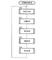
虫移動描画処理の基本フローは、各種パラメータを初期化する初期化処理(ステップS30)、虫の発生が求められるまで待機する待機処理(ステップS31)、発生した虫が画面内に飛来する飛来処理(ステップS32)、画面内で虫を移動する移動処理(ステップS33)、虫が画面から飛び去る飛去処理(ステップS34)の順となっている。発生する虫の数だけ独立に描画処理される。
【0115】
各処理の詳細について順次説明する。
【0116】
(初期化処理)
図15は初期化処理のフローチャートである。
【0117】
まず、表示部用の各種パラメータを初期化する(ステップS40)。
【0118】
次に、虫が発生する際の画面外の初期位置を乱数により設定する(ステップS41)。この初期位置から虫が飛来する。
【0119】
次に、発生した虫が着陸する着陸位置を乱数により設定する(ステップS42)。飛来した虫は最初この位置に着陸する。
【0120】
次に、滞在時間タイマを初期化する(ステップS43)。飛来してきた虫は一定時間が経過すると飛び去る。滞在時間タイマは虫が画面内で滞在する時間を計測する。
【0121】
次に、移動方向設定タイマを初期化する(ステップS44)。虫は動きながら移動方向を周囲の色情報に基づいて一定の頻度で再設定する。移動方向設定タイマは移動方向を再設定する時間を計測する。
【0122】
次に、進行方向揺らぎタイマを初期化する(ステップS45)。虫が自然に動いているように見せるために、一定の頻度で移動方向を少しずつずらす。進行方向揺らぎタイマは移動方向に揺らぎを発生する時間を計測する。
【0123】
初期化処理が終了すると、次の待機処理に進む。
【0124】
(待機処理)
図16は待機処理のフローチャートである。
【0125】
待機処理では、キャンパスに虫を発生する特定の色が描画されるまで待機し、特定の色が描画されれば、その色にしたがって発生する虫の種類を決定する。例えば、図24に示すように、赤色の線506が描画されていれば、赤色が好きな赤いてんとう虫508を発生し、青色の線510が描画されていれば青色が好きな虫512を発生する。
【0126】
まず、キャンパスに色が描画されてから一定時間が経過したか否か判断する(ステップS50)。キャンパスに色が描画されていなかったり、色が描画されても一定時間が経過していなければ、再びステップS50に戻る。
【0127】
キャンパスに色が描画されて一定時間が経過すると、続いて、虫が好きな色か否か、すなわち、虫を発生させる色か否か判断する(ステップS51)。虫が好きな色でなければ、再びステップS50に戻る。
【0128】
虫が好きな色のひとつであれば、その色に応じた虫の種類を決定する(ステップS52)。例えば、赤であればてんとう虫を選択し、青であれば青色が好きな虫を選択する。
【0129】
続いて、決定した虫の種類に基づいて、その虫が嫌いな色を設定する(ステップS53)。例えば、てんとう虫であれば緑を選択し、青色が好きな虫であれば茶色を選択する。
【0130】
待機処理が終了すると、次の飛来処理に進む。
【0131】
(飛来処理)
図17は飛来処理のフローチャートである。
【0132】
まず、図15の初期化処理のステップS41で定めた画面外の初期位置から、図16の待機処理のステップS52で定めた種類の虫を飛ばし(ステップS60)、図15の初期化処理のステップS42で定めた画面内の着陸位置に向かって飛ばす(ステップS61)。
【0133】
続いて、虫が着陸位置に到達したか否か判断する(ステップS62)。着陸位置に到達していなければ、再びステップS61に戻る。着陸位置に到達していれば飛来処理を終了し、次の移動処理に進む。
【0134】
(移動処理)
図18は移動処理のフローチャートであり、図19は移動処理中の進路決定処理のフローチャートであり、図20は移動処理中の移動境界チェック処理のフローチャートである。
【0135】
まず、図18に示すように、周囲の色情報にしたがって虫の進路を決定する進路決定処理を行う(ステップS71)。進路決定処理の詳細を図19を用いて説明する。
【0136】
進路決定処理においては、まず、移動方向設定タイマを減じ(ステップS90)、この移動方向設定タイマがゼロになったか否か判断する(ステップS91)。移動方向設定タイマがゼロになっていなければ、現在の進行方向を変更することなく維持して、移動処理を終了する。
【0137】
移動方向設定タイマがゼロになっていると、色情報ワークメモリを作成する(ステップS93)。色情報ワークメモリとは、進路決定の際に参照するために、虫の現在位置の周囲の色情報を検出して記憶するものである。虫の現在位置の周囲に、図22に示すように、16個の特定方向領域を設定する。これら16個の特定方向領域は、現在位置を中心として全周囲16方向の所定距離離れた位置に配置されている。各特定方向領域は、一定ドット数、例えば6ドットの面積である。
【0138】
進路決定部107は特定方向領域の色情報を読み込む。進路決定部107は特定方向領域の各ドットの読取り位置を座標変換部56に出力し、座標変換部116はバッファメモリ120のアドレスに変換し、その変換したアドレスのバッファメモリ120の色情報を色情報読出部118により読取り、進路決定部107に出力する。その色情報が、虫が好きな色か否か、嫌いな色か否かを判定し、それぞれカウントする。全ての16個の特定方向領域について色情報を読み取り、各特定方向領域についての好きな色の数と嫌いな色の数をカウントして、色情報ワークメモリに格納する。
【0139】
次に、色情報ワークメモリを参照して、虫の次の進行方向(以下「転回方向」という)を決定する(ステップS94)。現在の進行方向を中心として好きな色が多い方向を転回方向として決定するようにする。例えば、図23に示すように、現在の進行方向が右上方の方向(1)であるとすると、最初は、進行方向である右上方の方向(1)の特定方向領域を調査し、続いて、進行方向の左隣りの方向(2)の特定方向領域の色情報を調査し、続いて、進行方向の右隣りの方向(3)の特定方向領域の色情報を調査し、続いて、進行方向のさらに左隣りの方向(4)の特定方向領域の色情報を調査し、...順次、図23に丸数字で示した順番に進行方向を中心とする9個の特定方向領域の色情報を調査する。好きな色のドット数と嫌いな色の有無を調査する。
【0140】
調査の結果、最も好きな色のドット数が多い方向を転回方向とする。好きな色のドット数が同じであれば、図23に示した丸数字の少ない方向を転回方向として、現在の進行方向に近い方向を優先する。
【0141】
次に、ステップS94で調査した嫌いな色の有無から、調査した特定方向領域中で嫌いな色を含む特定方向領域の数をカウントする(ステップS95)。嫌いな色を含む特定方向領域が1個もなければ、ステップS94で決定した転回方向を維持してステップS97に進む。嫌いな色を含む特定方向領域が1個又は2個であれば、周囲に嫌いな色があると判断し、ステップS94で決定した転回方向を180度変更して(ステップS96)ステップS97に進む。嫌いな色を含む特定方向領域が3個以上であれば、周囲に嫌いな色がたくさんあると判断し、虫が飛び去る処理(ステップS34)に進む。
【0142】
次に、進行方向揺らぎタイマを減じ(ステップS97)、この進行方向揺らぎタイマがゼロになったか否か判断する(ステップS98)。進行方向揺らぎタイマがゼロになっていなければ、現在の進行方向を変更することなく維持して、進路決定処理を終了する。
【0143】
進行方向揺らぎタイマがゼロになっていれば、決定した転回方向に揺らぎを与える(ステップS99)。決定した転回方向と、転回方向から反時計回りに隣りの方向と、転回方向から時計回りに隣の方向という3つの方向から乱数に基づいていずれかの方向を選択し、新たな転回方向とする。
【0144】
ステップS71の進路決定処理により、周囲の色情報にしたがって虫の進路を決定すると、続いて、画面の縁で虫の移動を反転させるために移動境界チェック処理を行う(ステップS72)。移動境界チェック処理の詳細を図20を用いて説明する。
【0145】
移動境界チェック処理においては、まず、進路決定処理により決定された転回方向で進んだ場合、左右方向に関して画面からはみ出すか否か判断する(ステップS100)。はみ出すと判断された場合には、進行方向を左右逆にする(ステップS101)。
【0146】
次に、進路決定処理により決定された転回方向で進んだ場合、上下方向に関して画面からはみ出すか否か判断する(ステップS102)。はみ出すと判断された場合には、進行方向を上下逆にする(ステップS103)。
【0147】
このようにして決定された最終的な転回方向に現在の速度分を加えて、次の新しい座標を決定する(ステップS104)。このようにして決定された座標位置に虫が移動するように描画処理部104が虫を描画する。
【0148】
ステップS72の移動境界処理により最終的に次の新しい座標を決定すると、続いて、図18のステップS73以降の虫取りゲームの処理に進む。
【0149】
虫取りゲームの概要について説明する。遊戯者が虫取りゲームを行いたい場合には、タッチペン28をあみ領域213に接触して、図24に示すように、モニタ90に虫取り網のカーソル514を表示しておく。タッチペン28をお絵描きタブレット24に接触してペンボタン28aを押しながら動かすことにより、モニタ90上の虫508、512を捕まえて虫取り網514と一緒に動かすことができる。
【0150】
なお、電子カメラを利用する場合には、赤みに反応して網のカーソル514が移動するように設定すれば、例えば、遊戯者の手の移動に応じて網のカーソル514が画面上で移動するので、モニタ90上の虫508、512を捕まえて虫取り網514と一緒に動かすことができる。
【0151】
これとは別に、画面上に選択ボタン(図示せず)を表示させ、電子カメラ55に向けて手の移動させることによって、画面上のカーソルを移動させて、そのカーソルをその選択ボタンに重ねると、網のカーソル514に変化して表示するように制御してもよい。
【0152】
まず、タッチペン28による画面上のカーソルが虫に触っていて、かつ、ペンボタン28aが押されているか否か判断する(ステップS73)。画面上のカーソルが虫に触っていてペンボタン28aが押されていると判断されると、そのカーソルが虫取り網か否か判断する(ステップS74)。カーソルが虫取り網ではないと判断されると、次の飛び去り処理(ステップS34)に進む。
【0153】
なお、電子カメラを利用する場合には、画面上のカーソルが虫に触っていて、かつカーソルの移動スピードが所定のスピード以上であるときに飛び去り処理に進むようにしてもよい。現在のフレームと過去のフレームとの差から、カーソルの移動に要したフレーム数を求め、そのフレーム数に1/60秒(1フレームの時間)を乗算してスピードを計算する。
【0154】
カーソルが虫取り網であると判断されると、虫取り網から離されたか否か判断する(ステップS75)。離されていると判断されるとステップS77に戻り、上述した処理を繰り返す。虫取り網から離されていない場合には、虫が虫取り網に捕まえられていると判断し、虫取り網の中央の方向に虫が移動するように虫の新たな座標値を決定する(ステップS76)。続いて、再びステップS75に戻り、ステップS75、S76の処理を繰り返す。このようにすることにより、虫取り網514で虫508、510を捕まえて一緒に動かすことができる。
【0155】
ステップS73で、タッチペン28による画面上のカーソルが虫に触っていないと判断されると、続いて、画面が全消去されたか否か判断する(ステップS77)。画面が全消去されている場合には、次の飛び去り処理(ステップS34)に進む。
【0156】
画面が全消去されていない場合には、色情報ワークメモリを参照して、周囲にその虫が好きな色があるか否か判断する(ステップS78)。周囲に好きな色がある場合には、滞在時間タイマを初期化して(ステップS81)、ステップS77に戻り、上述した処理を繰り返す。
【0157】
周囲に好きな色がない場合には、滞在時間タイマを減じ(ステップS79)、この滞在時間タイマがゼロになったか否か判断する(ステップS80)。滞在時間タイマがゼロになっていなければ、ステップS77に戻り、上述した処理を繰り返す。滞在時間タイマがゼロになっていれば、次の飛び去り処理(ステップS34)に進む。
【0158】
(飛去処理)
図21は飛去処理のフローチャートである。
【0159】
まず、現在位置から虫を飛ばし(ステップS110)、画面外の所定の位置にに向かって飛ばす(ステップS111)。続いて、虫が画面外に出たか否か判断する(ステップS112)。画面外に出ていなければ、再びステップS111に戻る。画面外に出ていれば飛去処理を終了し、再び初期化処理(ステップS30)に戻り、上述した処理を繰り返す。
【0160】
このように、これら虫の発生及び移動は自動的に行われ、遊戯者による特別の操作を必要としないが、遊戯者はその虫を捕虫あみにより捕獲する等のゲームを行なうことができる。
【0161】
上述したような発音処理や移動体描画処理によれば、モニタに単に絵を描画するだけでなく、その絵を利用して音を発生したり、音楽を演奏したり、虫を捕獲したりする等の様々なゲームを行うことができる。
【0162】
(ビデオゲームの第2具体例)
次に、本実施形態のビデオゲーム装置のビデオゲームの第2の具体例について図25乃至図36を用いて説明する。第1の具体例とは発音処理及び移動体描画処理が異なっている。
【0163】
(発音処理2)
本具体例の発音処理について図25のフローチャートを用いて説明する。図26に示すグランドピアノのサンプル絵を用いて発音処理する場合として説明する。
【0164】
まず、タッチペン28によりどの種類の指揮棒が選択されたかどうか判断する(ステップS120)。本具体例では指揮棒として通常のオルガン音を奏でる指揮棒の他に他の動物の音色を発する指揮棒を選択することができる。指揮棒の種類は、図26に示すように、画面上にツールボックス520として表示することができ、遊戯者がタッチペン28を操作して、ツールボックス520内の動物の絵にカーソルを合わせペンボタン28aを押して好みの動物を選択する。例えば、ツールボックス520内の猫の絵522を選択すると、図26に示すように、先端が猫の絵の指揮棒524が表示される。
【0165】
なお、電子カメラ55を利用して選択する場合には、選択可能な複数種類の指揮棒ボタンを画面上に表示し、その中から希望の指揮ボタンに画面上のカーソルを重ねることで選択する。カーソルの移動は、例えば赤みに反応するように画像処理する設定にすれば、電子カメラ55に向かって遊戯者が手を移動すると、それに応じてカーソルを移動させることで実現できる。
【0166】
次に、タッチペン28がお絵描きタブレット24上にあるかどうか判断し(ステップS121)、更にペンボタン28aが押されているかどうか判断する(ステップS122)。遊戯者がタッチペン28をお絵描きタブレット24に接触すると、発音処理部108から位置信号が座標変換部116に出力され、バッファメモリ120のアドレスに変換される。続いて、色情報読出部118により、その変換したアドレスにおけるバッファメモリ120の色信号が読み出され、発音処理部108に出力される(ステップS123)。
【0167】
次に、色情報の変化があったか否か判断する(ステップS124)。色情報の変化がなかった場合にはペンボタン28aが押された直後か否か判断する(ステップS125)。ペンボタン28aが押された直後でなければステップS120に戻る。
【0168】
ペンボタン28aが押された直後であれば、発音処理部108は読み出された色情報が透明又は水又は黒であるか否か判断する(ステップS126)。透明又は水又は黒の場合は音を発生することなく、ステップS120に戻る。
【0169】
読み出された色情報が透明又は水又は黒でなければ、発音処理部108は、その色情報と指揮棒の種類に応じて発音する音を決定する(ステップS127)。指揮棒の種類に応じた音色(オルガン音、犬の声、猫の声、猿の声、豚の声、象の声)を定めると共に、各色情報に応じた音の周波数の倍率を定めた発声周波数表を定めておき、この音色と発声周波数表に基づいて発生音を定める。例えば、猫を選択した場合には、猫の声で音階を奏でることができる。
【0170】
続いて、発音処理部108は、決定された音信号を出力し、音声端子76を介してモニタ90に出力し、音を発生する(ステップS128)。
【0171】
図26では猫の指揮棒524が黄色の音符504上に位置しているので、猫の指揮棒と黄色に対して予め定められている音、例えば、猫の声で高さがレの音が発生する。
【0172】
このようにして、タッチペン28をお絵描きタブレット24上で移動してペンボタン28aを押すことにより、指示した色に応じた様々な音を発生することができる。
【0173】
(移動体描画処理1)
本具体例における動物を移動する動物移動描画処理について図27乃至図36用いて説明する。
【0174】
この動物移動描画処理は、絵本の動物の絵をクリックすることによりキャンパス内に動物を登場させ、その動物を色の線に沿って動かすものである。周囲の色情報により動物の絵が切り替わったり、ときどき休憩したりする。本具体例では、図34に示すように、かば221、ゴリラ222、ライオン232、鳥231、象234が絵本に描かれており、これら5種類の動物を登場させることができる。
【0175】
(基本フロー)
図27は動物移動描画処理の基本フローを示している。
【0176】
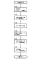
動物移動描画処理の基本フローは、各種パラメータを初期化する初期化処理(ステップS130)、動物の発生が求められるまで待機する待機処理(ステップS131)、選択された動物を画面内に登場させる登場処理(ステップS132)、画面内で動物を移動したり休憩したりする移動処理(ステップS133)、動物が画面から退場する退場処理(ステップS134)の順となっている。発生する動物の数だけ独立に描画処理される。
【0177】
各処理の詳細について順次説明する。
【0178】
(初期化処理)
図28は初期化処理のフローチャートである。
【0179】
まず、表示部用の各種パラメータを初期化する(ステップS140)。
【0180】
次に、動物が登場する際の画面外の初期位置を乱数により設定する(ステップS141)。この初期位置から動物が登場する。
【0181】
次に、登場する動物の種類に応じた好きな色を設定する(ステップS142)。例えば、カバであれば水色、象であれば草色が好きな色となる。
【0182】
次に、移動方向設定タイマを初期化する(ステップS143)。動物は動きながら移動方向を周囲の色情報に基づいて一定の頻度で再設定する。移動方向設定タイマは移動方向を再設定する時間を計測する。
【0183】
次に、進行方向揺らぎタイマを初期化する(ステップS144)。動物が自然に動いているように見せるために、一定の頻度で移動方向を少しずつずらす。進行方向揺らぎタイマは移動方向に揺らぎを発生する時間を計測する。
【0184】
次に、反転抑制タイマを初期化する(ステップS145)。動物の移動方向が反転した場合、その向きに応じて動物の画像を切り換えるが、動物が自然に動いているように見せるために、移動方向が反転しても直ちに動物の画像を切り換えることなく一定時間画像を反転するのを抑制する。反転抑制タイマは画像の反転を抑制する時間を計測する。
【0185】
初期化処理が終了すると、次の待機処理に進む。
【0186】
(待機処理)
図29は待機処理のフローチャートである。
【0187】
待機処理では、タッチペン28により絵本の動物の絵が触れられるまで待機し、触れられた動物を登場させるための準備を行う。
【0188】
まず、絵本の動物の絵がタッチペン28で触れられたか否か判断する(ステップS150)。タッチペン28でどこにも触れられていなかったり、触れられても動物の絵の位置でなければ、再びステップS150に戻る。
【0189】
タッチペン28により動物の絵が触れられていると、絵本タブレット32の出力から動物の種類を決定する(ステップS151)。
【0190】
なお、電子カメラ55を利用して選択する場合には、選択可能な動物の絵を画面上に表示し、その中から希望の動物の絵に画面上のカーソルを重ねることで選択する。
【0191】
続いて、動物が登場した際のキャンパス内の移動の終了位置を乱数で設定する(ステップS152)。
【0192】
待機処理が終了すると、次の登場処理に進む。
【0193】
(登場処理)
図30は登場処理のフローチャートである。
【0194】
まず、図28の初期化処理のステップS141で定めた画面外の初期位置から、図29の待機処理のステップS151で定めた種類の動物を登場させ(ステップS160)、図29の待機処理のステップS152で定めた画面内の終了位置に向かって移動する(ステップS161)。
【0195】
続いて、動物が終了位置に到達したか否か判断する(ステップS162)。終了位置に到達していなければ、再びステップS161に戻る。終了位置に到達していれば登場処理を終了し、次の移動処理に進む。
【0196】
(移動処理)
図31は移動処理のフローチャートであり、図32は移動処理中の速度設定・動物反転処理のフローチャートである。なお、移動処理中の進路決定処理と移動境界チェック処理の詳細については、第1の具体例と同様であるので説明を省略する。
【0197】
まず、図31に示すように、周囲の色情報にしたがって動物の進路を決定する進路決定処理を行う(ステップS170)。進路決定処理の詳細は第1の具体例の図19と同様であるが、第1の具体例と異なるのは、嫌いな色に関する処理を行っていない点である。
【0198】
ステップS170の進路決定処理により、周囲の色情報にしたがって動物の進路を決定すると、続いて、速度設定・動物反転処理を行う(ステップS171)。速度設定・動物反転処理の詳細について図32を用いて説明する。
【0199】
速度設定・動物判定処理においては、まず、進路決定処理により決定された転回方向から速度を決定し、水平方向及び垂直方向の速度成分を得る(ステップS181)。動物により移動速度が異なるので、速度変換テーブルから移動速度を読み取り、その移動速度と転回方向から、水平方向及び垂直方向の速度成分を得る。
【0200】
次に、現在の進行方向は、現在の動物の画像の左右の向きと一致しているか否か判断する(ステップS182)。各動物の画像として予め左向きの画像と右向きの画像が用意されている。速度の水平成分が左向きであれば動物の左向きの画像を表示し、右向きであれば右向きの画像を表示するようにしている。ステップS182では、動物の画像の向きが進行方向にあっているか否か判断する。
【0201】
現在の進行方向と動物の画像の向きが一致していないと判断されると、反転抑制タイマを減じ(ステップS183)、この反転抑制タイマがゼロになったか否か判断する(ステップS184)。反転抑制タイマがゼロになっていれば動物の画像を一致している向きの画像に切り換える(ステップS185)。
【0202】
ステップS182で現在の進行方向と動物の画像の左右の向きが一致していると判断された場合には、反転抑制タイマを初期化して(ステップS186)、次の移動境界チェック処理に進む。
【0203】
ステップS184で反転抑制タイマがゼロになっていないと判断された場合には、次の移動境界チェック処理に進む。
【0204】
続いて、画面の縁で動物を反転させるために移動境界チェック処理を行う(ステップS72)。移動境界チェック処理の詳細は第1の具体例の図20と同様であるので、説明を省略する。
【0205】
ステップS72の移動境界処理により最終的に次の新しい座標を決定すると、続いて、図31のステップS173以降の処理に進む。
【0206】
最初に周囲の色情報に基づいて動物の画像を切り換える処理を行う。
【0207】
まず、ステップS170の進路決定処理において作成した色情報ワークメモリを参照し、登場している動物の好きな色が周囲に何ドットあるかカウントし、例えば、46個以上あるか否か判断する(ステップS173)。46個以上であれば動物の画像を切り換える(ステップS174)。
【0208】
例えば、カバの場合、好きな水色530に囲まれた場合には水中にあるものと判断し、カバの画像を、図35に示す歩いているカバの画像532から図36の足が水中に没した泳いでいるカバの画像534に切り換える。図36に示すように、あたかもカバ534が水中530を泳いでいるかのように見える。他の動物についても好きな色に囲まれた場合に画像を切り換えることにより、リアリティのある画像表示を行うことができる。
【0209】
次に、動物が一定時間毎に休憩する処理を行う。一定時間毎に移動を一時休止し、休憩状態の動物の画像を表示する。休憩時間が終了すれば再び移動を開始する。各動物に対して休憩時間タイマを設定しておく。動物により休憩時間タイマの時間が異なる。
【0210】
まず、休憩のタイミングか否か判断する(ステップS175)。休憩のタイミングであれば、休憩状態の動物の画像を表示する(ステップS176)。休憩のタイミングでなければ、ステップS178に進む。
【0211】
続いて、休憩時間を計測する休憩時間タイマがゼロになった否か判断する(ステップS177)。休憩時間タイマがゼロであれば、休憩終了の動物の画像を表示する(ステップS180)。
【0212】
次に、動物の画像をクリックすることにより鳴き声を発生させる処理を行う。タッチペン28を操作して、画面上の動物にカーソルを合わせ、クリックすると、その動物が画像を変化して鳴き声を発生する。
【0213】
まず、動物上にカーソルがあってタッチペン28がクリックされたか否か判断する(ステップS178)。クリックされた場合には、鳴き声を発生する動物の画像を表示すると共に、鳴き声を発生する(ステップS179)。
【0214】
なお、電子カメラ55を利用して選択する場合には、選択可能な動物の絵を画面上に表示し、その中から希望の動物の絵に画面上のカーソルを重ね、カーソルを左右に振ることで選択する。
【0215】
(退場処理)
図33は退場処理のフローチャートである。
【0216】
まず、絵本の動物の絵がタッチペン28で触れられたか否か判断する(ステップS190)。タッチペン28でどこにも触れられていなかったり、触れられても動物の絵の位置でなければ、再び初期化処理(ステップS130)に戻り、上述した処理を繰り返す。
【0217】
タッチペン28により動物の絵が触れられていれば、表示されている動物を画面外に退場させる退場処理を行う。その動物の画像を画面外の所定の位置に向かって移動する(ステップS191)。続いて、動物が画面外に出たか否か判断する(ステップS192)。画面外に出ていなければ、再びステップS191に戻る。画面外に出ていれば退場処理を終了し、再び初期化処理(ステップS130)に戻り、上述した処理を繰り返す。
【0218】
このように、遊戯者の指示にしたがって動物を発生させ、描いた絵の色情報にしたがって移動させ、画像を切り換えたり、休憩させたり、鳴き声を鳴かせたりといって種々のゲームを行うことができる。
【0219】
なお、電子カメラ55を利用する場合には、入力手段としてタッチペン28を用いるか電子カメラ55を用いるかを選択できるような選択手段又は切換手段を設けるようにする。この選択手段又は切換手段は切換スイッチ等のハードウエアとして設けてもよいし、画面上で選択できるようにするプログラム等のソフトウエアとして設けてもよい
また、電子カメラ55による操作入力とタッチペン28による操作入力を共に可能なようにして、双方の入力手段を同時に用いられるようにしてもよい。例えば、子供はタッチペン28により操作入力し、親は電子カメラ55を利用して操作入力できるようにする。表示画面上にはそれぞれ独立に操作できるカーソルを表示し、それぞれの操作入力に応じた操作表示、例えば、カーソルで線図を書く入力操作を同じ画面上に表示するようにしてもよい。
【0220】
[変形実施形態]
本発明は上記実施形態に限らず種々の変形が可能である。
【0221】
例えば、上記実施形態では幼児用ビデオゲーム装置を用いたが、基本的な構成は上記実施形態と同様に構成し、他のゲーム装置に本発明を適用してもよい。
【0222】
また、ゲーム装置に限らず、基本的な構成は上記実施形態と同様に構成し、電子的に絵を書く電子タブレットのような電子タブレットに本発明を適用してもよい。
【0223】
また、基本的な構成は上記実施形態と同様に構成し、パーソナルコンピュータ等の汎用のコンピュータにおけるゲームプログラムや画像プログラム等の画像処理に本発明を適用してもよい。
【0224】
また、基本的な構成は上記実施形態と同様に構成し、音楽に合わせて操作を行う音楽ゲーム等の他のゲームに本発明を適用してもよい。
【0225】
【発明の効果】
以上の通り、本発明によれば、画像を撮像する撮像手段と、撮像手段により撮像した画像データを複数フレーム分記憶する記憶手段と、記憶手段に記憶された画像データを表示画面上に順次表示する画像表示手段と、一のフレームの画像データと他のフレームの画像データとを比較して得られる差分データを算出する差分算出手段とを有し、差分算出手段により算出された差分データに基づいて表示画面上に表示する移動体の挙動を決定するようにしたので、遊戯者等の撮像画像から特定の情報を得て、その情報に基づいて画像表示を制御することができる。
【図面の簡単な説明】
【図1】本発明の第1実施形態によるビデオゲーム装置の機能を示すブロック図である。
【図2】本発明の第1実施形態によるビデオゲーム装置の遊戯方法の第1の具体例を示す説明図である。
【図3】本発明の第1実施形態によるビデオゲーム装置の遊戯方法の第2の具体例を示す説明図である。
【図4】本発明の第1実施形態によるビデオゲーム装置の遊戯方法の第3の具体例を示す説明図である。
【図5】本発明の第2実施形態によるビデオゲーム装置の外観を示す斜視図である。
【図6】本発明の第2実施形態によるビデオゲーム装置のソフトウエアカートリッジを示す図である。
【図7】本発明の第2実施形態によるビデオゲーム装置のハードウエアの構成を示すブロック図である。
【図8】本発明の第2実施形態によるビデオゲーム装置の機能ブロック図である。
【図9】本発明の第2実施形態におけるビデオゲームの第1の具体例におけるソフトウエアカートリッジの絵本の絵の一例を示す図である。
【図10】本発明の第2実施形態におけるビデオゲームの第1の具体例における描画処理のフローチャートである。
【図11】本発明の第2実施形態におけるビデオゲームの第1の具体例におけるサンプル絵の一例を示す図である。
【図12】本発明の第2実施形態におけるビデオゲームの第1の具体例におけるキャンパスの絵の一例を示す図である。
【図13】本発明の第2実施形態におけるビデオゲームの第1の具体例における発音処理のフローチャートである。
【図14】本発明の第2実施形態におけるビデオゲームの第1の具体例における虫移動描画処理のフローチャートである。
【図15】本発明の第2実施形態におけるビデオゲームの第1の具体例における初期化処理のフローチャートである。
【図16】本発明の第2実施形態におけるビデオゲームの第1の具体例における待機処理のフローチャートである。
【図17】本発明の第2実施形態におけるビデオゲームの第1の具体例における飛来処理のフローチャートである。
【図18】本発明の第2実施形態におけるビデオゲームの第1の具体例における移動処理のフローチャートである。
【図19】本発明の第2実施形態におけるビデオゲームの第1の具体例における進路決定処理のフローチャートである。
【図20】本発明の第2実施形態におけるビデオゲームの第1の具体例における移動境界チェック処理のフローチャートである。
【図21】本発明の第2実施形態におけるビデオゲームの第1の具体例における飛去処理のフローチャートである。
【図22】本発明の第2実施形態におけるビデオゲームの第1の具体例における進路決定処理の説明図である。
【図23】本発明の第2実施形態におけるビデオゲームの第1の具体例における進路決定処理の説明図である。
【図24】本発明の第2実施形態におけるビデオゲームの第1の具体例におけるキャンパスの絵の一例を示す図である。
【図25】本発明の第2実施形態におけるビデオゲームの第2の具体例における発音処理のフローチャートである。
【図26】本発明の第2実施形態におけるビデオゲームの第2の具体例におけるサンプル絵の具体例を示す図である。
【図27】本発明の第2実施形態におけるビデオゲームの第2の具体例における動物移動描画処理のフローチャートである。
【図28】本発明の第2実施形態におけるビデオゲームの第2の具体例における初期化処理のフローチャートである。
【図29】本発明の第2実施形態におけるビデオゲームの第2の具体例における待機処理のフローチャートである。
【図30】本発明の第2実施形態におけるビデオゲームの第2の具体例における登場処理のフローチャートである。
【図31】本発明の第2実施形態におけるビデオゲームの第2の具体例における移動処理のフローチャートである。
【図32】本発明の第2実施形態におけるビデオゲームの第2の具体例における速度設定・動物反転処理のフローチャートである。
【図33】本発明の第2実施形態におけるビデオゲームの第2の具体例における退場処理のフローチャートである。
【図34】本発明の第2実施形態におけるビデオゲームの第2の具体例におけるソフトウエアカートリッジの絵本の絵の一例を示す図である。
【図35】本発明の第2実施形態におけるビデオゲームの第2の具体例におけるキャンパスの絵の一例を示す図である。
【図36】本発明の第2実施形態におけるビデオゲームの第2の具体例におけるキャンパスの絵の一例を示す図である。
【符号の説明】
10…ゲーム装置本体
12…ソフトウエアカートリッジ
14…底蓋
16…上蓋
18…カートリッジスロット
20…方向ボタン
22…実行ボタン
24…お絵描きタブレット
26…タッチペンホルダ
28…タッチペン
28a…ペンボタン
32…絵本タブレット
34…パワースイッチ
36…リジェクトボタン
38…ページセンサ
40…綴じリング
42…ページ
46…絵本載置部
48…回路基板
50…基板収納部
52…センサ用穴
54…プログラムROM
55…電子カメラ
60…MPU
62…RAM
64…ビデオディスプレイプロセッサ(VDP)
66…ビデオRAM
70…映像端子
72…音声合成LSI
76…音声端子
78…コントローラ
80…アナログスイッチ
84…アドレスバス
86…データバス
88…コントロールバス
90…モニタ
100…制御部
102…描画制御部
103…描画処理部
106…移動体描画部
107…進路決定部
110…バッファメモリ入出力部
112…座標変換部
114…色情報書込部
116…座標変換部
118…色情報読取部
120…バッファメモリ
200…ゲーム装置
202…CPU
204…システムメモリ
206…プログラムデータ記憶装置又は記憶媒体
208…BOOTROM
210…バスアービタ
212…レンダリングプロセッサ
214…グラフィックメモリ
216…ディスプレイモニタ
218…オーディオプロセッサ
220…オーディオメモリ
222…スピーカ
224…モデム
226…コントローラ
228…バックアップメモリ
230…マイク
232…電子カメラ
300、310…遊戯者
302、304…移動体
314…指示棒[0001]
BACKGROUND OF THE INVENTION
The present invention relates to an image processing system that captures an image of a player and uses the captured image.
[0002]
[Prior art]
Arcade game devices and home video game devices installed in game centers and the like have recently developed a wide variety of interesting games, and are very popular as entertainment.
[0003]
A conventional game device is known in which a player is imaged and the captured image is used. For example, like a print club, you can capture a player's image, print it in combination with the background, and provide it to the player, or capture the player's face image and paste it on the game character's face. There are things that create new characters.
[0004]
Further, in a conventional game device, a position on the display screen is instructed by a position instructing unit such as a controller, and the game is controlled based on the color information displayed at the instructed position, or a specific moving body There are things that generate.
[0005]
[Problems to be solved by the invention]
However, in the conventional game device, even if a player is imaged, all or part of the captured image is used as an image, and specific information is not obtained from the captured image.
[0006]
An object of the present invention is to provide an image processing system that obtains specific information from a captured image of a player or the like and controls image display based on the information.
[0007]
Another object of the present invention is to provide an image processing system capable of moving a moving body smoothly and uniquely in relation to a player's instruction.
[0008]
Still another object of the present invention is to provide an image processing system capable of smoothly performing operation input from a player.
[0009]
[Means for Solving the Problems]
An image processing system according to the present invention includes an imaging unit that captures an image of a player, a storage unit that stores a plurality of frames of image data captured by the imaging unit, and image data stored in the storage unit on a display screen. Image display means for sequentially displaying the difference, and difference calculation means for obtaining a difference by comparing the currently displayed image data with the image data displayed in the past, and the difference calculated by the difference calculation means Based on this, the behavior of the moving body displayed on the display screen is determined.
[0010]
In addition, an image processing system according to the present invention includes an imaging unit that captures an image of a player, a storage unit that stores a plurality of frames of image data captured by the imaging unit, and displays image data stored in the storage unit. The image display means for sequentially displaying on the screen, and the presently displayed image data and the previously displayed image data in a predetermined area in the display screen are compared with each other to obtain a difference between predetermined color components. And a difference calculating means for obtaining, when the difference between the predetermined color components calculated by the difference calculating means is greater than or equal to a predetermined value, it is determined that there has been a predetermined operation input from the player. And
[0011]
DETAILED DESCRIPTION OF THE INVENTION
[First Embodiment]
A video game apparatus according to a first embodiment of the present invention will be described with reference to FIGS. FIG. 1 is a block diagram showing functions of the video game apparatus according to the present embodiment, FIG. 2 is an explanatory diagram showing a first specific example of the playing method of the video game apparatus according to the present embodiment, and FIG. FIG. 4 is an explanatory view showing a second specific example of the playing method of the video game apparatus of the embodiment, and FIG. 4 is an explanatory view showing a third specific example of the playing method of the video game apparatus of the present embodiment.
[0012]
As shown in FIG. 1, the
[0013]
Further, as a program data storage device or
[0014]
Further, a
[0015]
Also, an
[0016]
The
[0017]
In addition, a
[0018]
Further, in order to input a player's image and sound, the
[0019]
A first specific example of the playing method using the video game apparatus of this embodiment will be described with reference to FIG.
[0020]
In this specific example, the
[0021]
In this specific example, an image is captured by the
[0022]
Since the
[0023]
In this specific example, image data captured by the
[0024]
In this specific example, a difference between current image data and past image data stored in the
[0025]
In this specific example, the moving body is controlled based on the difference data of each color component. This prevents the moving image data such as the background from being affected. For example, since a human hand has many redness components, when the
[0026]
Therefore, in the present embodiment, when the difference value of the redness component becomes equal to or larger than a predetermined value, for example, the moving
[0027]
The algorithm for generating, following, and disappearing the moving
[0028]
When the moving
[0029]
In this specific example, as shown in FIG. 2, another moving
[0030]
Further, the algorithm of the animal movement drawing process (FIGS. 27 to 36) in the second embodiment of the present invention to be described later may be used as the algorithm of the process for the moving
[0031]
As described above, according to this specific example, since the redness component of the human hand is used, it is not necessary to attach a special device to clothes or hands, and it can be used as a simpler character input means. The moving body can be moved smoothly and uniquely in relation to the user's instructions.
[0032]
Further, instead of using the redness component of the human hand, a special tool may be attached. For example, an effective display as in this specific example may be performed by operating a command stick with a red tip instead of a hand. Further, a red glove may be attached to the right hand and a blue glove may be attached to the left hand, and the moving
[0033]
A second specific example of the playing method using the video game apparatus of this embodiment will be described with reference to FIG.
[0034]
In this specific example, as in the first specific example, the image data captured by the
[0035]
In this specific example, a
[0036]
When the
[0037]
It should be noted that the
[0038]
As described above, according to the present specific example, it is only necessary to move the operation means such as the pointing rod, so that it can be used as a simpler operation input means, and the operation input from the player can be performed smoothly.
[0039]
A third specific example of the playing method using the video game apparatus of the present embodiment will be described with reference to FIG.
[0040]
In this specific example, as in the first specific example, the image data captured by the
[0041]
In this specific example, a player's intentional operation is detected and activated in response to the start of the game. When the player shakes his / her hand in front of the
[0042]
On the initial screen, as shown in FIG. 4A, a
[0043]
When the player moves the
[0044]
Various measures are taken to prevent the game from being determined to be started by an unintended movement by the player. For example, the movement distance is accumulated in consideration of the speed of hand movement. When the speed of the hand movement is equal to or greater than a predetermined value, the movement distance is accumulated as it is. However, when the movement of the hand is equal to or smaller than the predetermined value, a value obtained by subtracting the predetermined distance from the actual movement distance is accumulated. If the accumulated distance does not reach the predetermined value for starting the game even after a predetermined time has elapsed since the hand movement was detected, the accumulated distance is reset.
[0045]
In the above embodiment, the player's
[0046]
Thus, according to this specific example, the player can give an operation instruction such as starting a game by waving his hand in front of the electronic camera, and the player can smoothly input the operation.
[0047]
[Second Embodiment]
A video game apparatus according to a second embodiment of the present invention will be described with reference to FIGS. FIG. 5 is a perspective view showing the appearance of the video game apparatus of the present embodiment, FIG. 6 is a software cartridge of the video game apparatus of the present embodiment, and FIG. 7 shows the hardware of the video game apparatus of the present embodiment. FIG. 8 is a block diagram showing functions of the video game apparatus according to the present embodiment.
[0048]
(Game device itself)
The video game apparatus of the present embodiment is one in which a picture book
[0049]
As will be described later, in the present embodiment, it is also possible to provide an
[0050]
Inside the
[0051]
The
[0052]
The drawing
[0053]
A
[0054]
A
[0055]
A
[0056]
As shown in FIG. 5, the
[0057]
(Software cartridge)
The
[0058]
The upper part of the
[0059]
A binding
[0060]
A
[0061]
(Hardware)
Next, the hardware configuration of the video game apparatus of this embodiment will be described with reference to FIG.
[0062]
The
[0063]
When the
[0064]
A voice synthesis LSI (ADPCM) 72 synthesizes all voices such as words spoken by the character. Synthesize and pronounce the sound according to the game. The audio signal from the
[0065]
The
[0066]
The
[0067]
When the
[0068]
The
[0069]
In the
[0070]
(Function block diagram)
Next, functions of the video game apparatus according to the present embodiment will be described with reference to the block diagram of FIG. FIG. 8 is a functional block diagram when the
[0071]
The
[0072]
When the
[0073]
The buffer memory input / output unit 110 writes color information into the
[0074]
When writing color information, the coordinate
[0075]
When reading the color information, the reading position from the
[0076]
As the video information, an image based on the color information stored in the
[0077]
As the audio information, the audio signal output from the sound
[0078]
(First example of video game)
Next, a first specific example of the video game of the video game apparatus according to the present embodiment will be described with reference to FIGS.
[0079]
(Basic drawing process)
The drawing process of this example will be described with reference to FIGS.
[0080]
FIG. 9 is a specific example of a picture of the
[0081]
When the
[0082]
In the
[0083]
In the
[0084]
The drawing process will be described with reference to the flowchart of FIG.
[0085]
First, it is determined whether a sample picture is selected with the touch pen 28 (step S10). When the player touches the
[0086]
When using the
[0087]
Further, when a desired function is selected by touching the sample area, pencil area, eraser area, and color designation area with the
[0088]
If no sample picture has been selected, it is determined whether or not the campus has been selected with the touch pen 28 (step S12). When the player touches the
[0089]
Next, a diagram is drawn on the
[0090]
In the case of using the
[0091]
First, it is determined whether a pencil and a color are selected by the touch pen 28 (step S14). When the
[0092]
Next, it is determined whether or not the
[0093]
When using the
[0094]
When the
[0095]
In the case of using the
[0096]
Furthermore, if the player moves his / her hand toward the
[0097]
When using the
[0098]
(Sounding process 1)
The sound generation process of this example will be described with reference to the flowchart of FIG. The case where sound generation processing is performed using the sample picture of the grand piano shown in FIG. 11 will be described, but sound generation processing can also be performed using the diagram on the campus shown in FIG.
[0099]
First, it is determined whether or not a baton has been selected with the touch pen 28 (step S20). When the player touches the
[0100]
Next, it is determined whether or not the
[0101]
When the
[0102]
Next, it is determined whether or not the color information has changed (step S24). If there is no change in the color information, it is determined whether or not it is immediately after the
[0103]
If it is immediately after the
[0104]
When the
[0105]
If the read color information is not transparent or black, the sound
[0106]
In FIG. 11, since the
[0107]
In this way, by moving the
[0108]
Further, when the
[0109]
Furthermore, as shown in FIG. 11, if the piano keyboard is drawn in a color that matches the pitch, simple music can be freely played by instructing the piano keyboard with the
[0110]
When the
[0111]
(Moving object drawing process 1)
Insect movement drawing processing for moving insects in this specific example will be described with reference to FIGS.
[0112]
In this insect movement drawing process, the moving object drawing unit 106 automatically generates an insect that likes the color according to the color used in the campus diagram, and moves the insect along the color line. It is. The player can play a game such as catching the insect by catching insects.
[0113]
(Basic flow)
FIG. 14 shows a basic flow of the insect movement drawing process.
[0114]
The basic flow of the insect movement drawing process includes an initialization process for initializing various parameters (step S30), a standby process for waiting for the occurrence of insects (step S31), and a flying process for causing the insects to fly into the screen. (Step S32), the movement process (Step S33) for moving the insect within the screen, and the flying process (Step S34) for the insect to fly off the screen. The drawing process is performed independently for the number of insects that occur.
[0115]
Details of each process will be sequentially described.
[0116]
(Initialization process)
FIG. 15 is a flowchart of the initialization process.
[0117]
First, various parameters for the display unit are initialized (step S40).
[0118]
Next, an initial position outside the screen when the insect is generated is set by a random number (step S41). Insects fly from this initial position.
[0119]
Next, a landing position where the generated insects land is set by a random number (step S42). The flying insect will land at this position first.
[0120]
Next, the dwell time timer is initialized (step S43). The flying insects fly away after a certain time. The stay time timer measures the time that the insect stays on the screen.
[0121]
Next, the moving direction setting timer is initialized (step S44). The insect resets the moving direction at a certain frequency based on the surrounding color information while moving. The movement direction setting timer measures the time for resetting the movement direction.
[0122]
Next, the traveling direction fluctuation timer is initialized (step S45). In order to make the insects appear to move naturally, the direction of movement is shifted little by little at a certain frequency. The traveling direction fluctuation timer measures the time for generating fluctuation in the moving direction.
[0123]
When the initialization process ends, the process proceeds to the next standby process.
[0124]
(Standby processing)
FIG. 16 is a flowchart of standby processing.
[0125]
In the standby process, the process waits until a specific color that generates an insect is drawn on the campus. If the specific color is drawn, the type of the insect to be generated is determined according to the color. For example, as shown in FIG. 24, if a
[0126]
First, it is determined whether or not a predetermined time has elapsed since the color was drawn on the campus (step S50). If no color is drawn on the campus or if a certain time has not passed even if the color is drawn, the process returns to step S50 again.
[0127]
When a certain period of time has elapsed since the color was drawn on the campus, it is then determined whether or not the insect is a favorite color, that is, whether or not it is a color that generates the insect (step S51). If the insect does not like the color, the process returns to step S50 again.
[0128]
If the insect is one of the favorite colors, the insect type corresponding to that color is determined (step S52). For example, a ladybug is selected if it is red, and an insect that likes blue is selected if it is blue.
[0129]
Subsequently, based on the determined insect type, a color that the insect does not like is set (step S53). For example, green is selected for ladybugs, and brown is selected for insects that like blue.
[0130]
When the standby process ends, the process proceeds to the next incoming process.
[0131]
(Flying process)
FIG. 17 is a flowchart of the incoming process.
[0132]
First, from the initial position outside the screen determined in step S41 of the initialization process of FIG. 15, the type of insects determined in step S52 of the standby process of FIG. 16 are skipped (step S60), and the initialization process steps of FIG. Fly toward the landing position in the screen determined in S42 (step S61).
[0133]
Subsequently, it is determined whether or not the insect has reached the landing position (step S62). If the landing position has not been reached, the process returns to step S61 again. If the landing position has been reached, the flying process is terminated and the process proceeds to the next movement process.
[0134]
(Move process)
FIG. 18 is a flowchart of the movement process, FIG. 19 is a flowchart of the course determination process during the movement process, and FIG. 20 is a flowchart of the movement boundary check process during the movement process.
[0135]
First, as shown in FIG. 18, a course determination process for determining the path of insects according to surrounding color information is performed (step S71). Details of the course determination process will be described with reference to FIG.
[0136]
In the course determination process, first, the moving direction setting timer is decremented (step S90), and it is determined whether or not the moving direction setting timer has become zero (step S91). If the movement direction setting timer is not zero, the current traveling direction is maintained without being changed, and the movement process is terminated.
[0137]
If the moving direction setting timer is zero, a color information work memory is created (step S93). The color information work memory detects and stores color information around the current position of the insect for reference when determining the course. Sixteen specific direction areas are set around the current position of the insect as shown in FIG. These 16 specific direction areas are arranged at a predetermined distance apart in 16 directions around the current position. Each specific direction region has a certain number of dots, for example, an area of 6 dots.
[0138]
The course decision unit 107 reads the color information of the specific direction area. The course determination unit 107 outputs the reading position of each dot in the specific direction area to the coordinate conversion unit 56, and the coordinate
[0139]
Next, referring to the color information work memory, the next traveling direction of the insect (hereinafter referred to as “turning direction”) is determined (step S94). The direction with many favorite colors around the current traveling direction is determined as the turning direction. For example, as shown in FIG. 23, assuming that the current traveling direction is the upper right direction (1), first, the specific direction area in the upper right direction (1), which is the traveling direction, is investigated, and then The color information of the specific direction area in the direction (2) to the left of the traveling direction is checked, and the color information of the specific direction area in the direction (3) to the right of the travel direction is checked. Investigate the color information of the specific direction area in the direction (4) that is further to the left of the direction. . . Sequentially, the color information of nine specific direction areas centering on the traveling direction is examined in the order indicated by the circled numbers in FIG. Investigate the number of dots of your favorite color and the presence of disliked colors.
[0140]
As a result of the investigation, the direction in which the number of dots of the most favorite color is large is set as the turning direction. If the number of dots of the favorite color is the same, priority is given to the direction closer to the current traveling direction, with the direction with a small number of circles shown in FIG.
[0141]
Next, from the presence / absence of the disliked color investigated in step S94, the number of specific direction areas including the disliked color in the investigated specific direction area is counted (step S95). If there is no specific direction area including the disliked color, the turning direction determined in step S94 is maintained and the process proceeds to step S97. If there are one or two specific direction areas including disliked colors, it is determined that there are disliked colors in the surroundings, the turning direction determined in step S94 is changed by 180 degrees (step S96), and the process proceeds to step S97. . If there are three or more specific direction areas including disliked colors, it is determined that there are a lot of disliked colors in the surroundings, and the process proceeds to the process of flying away insects (step S34).
[0142]
Next, the traveling direction fluctuation timer is decremented (step S97), and it is determined whether or not the traveling direction fluctuation timer has become zero (step S98). If the traveling direction fluctuation timer is not zero, the current traveling direction is maintained without being changed, and the course determination process is terminated.
[0143]
If the traveling direction fluctuation timer is zero, fluctuation is given to the determined turning direction (step S99). Based on the random number, select one direction based on the random number from the determined direction of rotation, the next direction counterclockwise from the direction of rotation, and the next direction clockwise from the direction of rotation. .
[0144]
When the path of the insect is determined according to the surrounding color information by the path determination process in step S71, a movement boundary check process is subsequently performed to reverse the movement of the insect at the edge of the screen (step S72). Details of the moving boundary check process will be described with reference to FIG.
[0145]
In the movement boundary check process, first, when the vehicle travels in the turning direction determined by the course determination process, it is determined whether or not the screen will protrude from the screen in the left-right direction (step S100). If it is determined that it will protrude, the direction of travel is reversed left and right (step S101).
[0146]
Next, when the vehicle travels in the turning direction determined by the course determination process, it is determined whether or not the screen protrudes from the screen in the vertical direction (step S102). If it is determined that it will protrude, the traveling direction is turned upside down (step S103).
[0147]
The current speed is added to the final turning direction determined in this way to determine the next new coordinate (step S104). The drawing processing unit 104 draws the insect so that the insect moves to the coordinate position thus determined.
[0148]
When the next new coordinates are finally determined by the moving boundary process in step S72, the process proceeds to the bug removing game process in step S73 and subsequent steps in FIG.
[0149]
An outline of the bug trapping game will be described. When the player wants to play a bug catching game, the
[0150]
Note that when using an electronic camera, if the
[0151]
Separately, when a selection button (not shown) is displayed on the screen and the hand is moved toward the
[0152]
First, it is determined whether or not the cursor on the screen by the
[0153]
When using the electronic camera, the cursor may be touched by a bug on the screen, and the process may be skipped when the moving speed of the cursor is equal to or higher than a predetermined speed. The number of frames required to move the cursor is obtained from the difference between the current frame and the past frame, and the speed is calculated by multiplying the number of frames by 1/60 seconds (one frame time).
[0154]
If it is determined that the cursor is a insect net, it is determined whether or not the cursor is separated from the insect net (step S75). If it is determined that they are separated, the process returns to step S77 and the above-described processing is repeated. If it is not separated from the insect trapping net, it is determined that the insect is caught by the insect trapping net, and a new coordinate value of the insect is determined so that the insect moves toward the center of the insect trapping net ( Step S76). Subsequently, the process returns to step S75 again, and the processes of steps S75 and S76 are repeated. In this way, the
[0155]
If it is determined in step S73 that the cursor on the screen by the
[0156]
If the entire screen has not been erased, it is determined by referring to the color information work memory whether there is a color that the insect likes in the surroundings (step S78). If there is a favorite color in the surroundings, the dwell time timer is initialized (step S81), the process returns to step S77, and the above-described processing is repeated.
[0157]
If there is no favorite color in the surroundings, the stay time timer is decreased (step S79), and it is determined whether or not this stay time timer has become zero (step S80). If the stay time timer is not zero, the process returns to step S77 and the above-described processing is repeated. If the stay time timer has become zero, the process proceeds to the next fly-off process (step S34).
[0158]
(Flying process)
FIG. 21 is a flowchart of the flying process.
[0159]
First, the insect is blown from the current position (step S110), and is blown toward a predetermined position outside the screen (step S111). Subsequently, it is determined whether or not the insect has gone out of the screen (step S112). If it is not out of the screen, the process returns to step S111 again. If it is outside the screen, the flying process is terminated, the process returns to the initialization process (step S30) again, and the above-described process is repeated.
[0160]
In this way, the generation and movement of these insects are performed automatically, and no special operation by the player is required, but the player can play a game such as capturing the insect by catching insects.
[0161]
According to the sound generation process and the moving object drawing process as described above, the picture is not simply drawn on the monitor, but the picture is used to generate a sound, play music, or catch an insect. Various games such as can be performed.
[0162]
(Second specific example of video game)
Next, a second specific example of the video game of the video game apparatus according to the present embodiment will be described with reference to FIGS. The sound generation process and the moving object drawing process are different from the first specific example.
[0163]
(Sound production process 2)
The sound generation process of this example will be described with reference to the flowchart of FIG. A case where sound generation processing is performed using the sample picture of the grand piano shown in FIG. 26 will be described.
[0164]
First, it is determined which type of command stick has been selected by the touch pen 28 (step S120). In this specific example, a command bar that emits the tone of another animal can be selected in addition to a command bar that plays a normal organ sound. As shown in FIG. 26, the type of baton can be displayed on the screen as a
[0165]
When the
[0166]
Next, it is determined whether or not the
[0167]
Next, it is determined whether or not the color information has changed (step S124). If there is no change in color information, it is determined whether or not it is immediately after the
[0168]
If it is immediately after the
[0169]
If the read color information is not transparent or water or black, the sound
[0170]
Subsequently, the sound
[0171]
In FIG. 26, since the
[0172]
In this way, by moving the
[0173]
(Moving object drawing process 1)
An animal movement drawing process for moving an animal in this example will be described with reference to FIGS.
[0174]
In this animal movement drawing process, an animal appears on the campus by clicking on the picture of the animal in the picture book, and the animal is moved along the color line. Depending on the color information of the surroundings, the picture of the animal changes and sometimes takes a break. In this specific example, as shown in FIG. 34, a
[0175]
(Basic flow)
FIG. 27 shows a basic flow of the animal movement drawing process.
[0176]
The basic flow of the animal movement drawing process includes an initialization process for initializing various parameters (step S130), a standby process for waiting until an animal is requested (step S131), and an appearance for causing the selected animal to appear on the screen. Processing (step S132), movement processing for moving or resting animals on the screen (step S133), and exit processing for leaving animals from the screen (step S134) are performed in this order. The drawing process is independently performed for the number of animals generated.
[0177]
Details of each process will be sequentially described.
[0178]
(Initialization process)
FIG. 28 is a flowchart of the initialization process.
[0179]
First, various parameters for the display unit are initialized (step S140).
[0180]
Next, an initial position outside the screen when the animal appears is set by a random number (step S141). Animals appear from this initial position.
[0181]
Next, the favorite color according to the kind of animal which appears is set (step S142). For example, if you are a hippopotamus, if you are an elephant, you like a grass color.
[0182]
Next, the moving direction setting timer is initialized (step S143). The animal resets the moving direction at a certain frequency based on the surrounding color information while moving. The movement direction setting timer measures the time for resetting the movement direction.
[0183]
Next, the traveling direction fluctuation timer is initialized (step S144). In order to make the animal appear to move naturally, the movement direction is gradually shifted at a certain frequency. The traveling direction fluctuation timer measures the time for generating fluctuation in the moving direction.
[0184]
Next, the inversion suppression timer is initialized (step S145). When the moving direction of the animal is reversed, the image of the animal is switched according to the direction. However, in order to make the animal appear to move naturally, the animal image is not changed immediately even if the moving direction is reversed. Suppresses the inversion of the time image. The inversion suppression timer measures the time for suppressing the inversion of the image.
[0185]
When the initialization process ends, the process proceeds to the next standby process.
[0186]
(Standby processing)
FIG. 29 is a flowchart of standby processing.
[0187]
In the waiting process, the process waits until the animal picture in the picture book is touched with the
[0188]
First, it is determined whether or not an animal picture in the picture book has been touched with the touch pen 28 (step S150). If it is not touched anywhere with the
[0189]
If an animal picture is touched by the
[0190]
When the
[0191]
Subsequently, the end position of the movement within the campus when the animal appears is set with a random number (step S152).
[0192]
When the standby process ends, the process proceeds to the next appearance process.
[0193]
(Appearance process)
FIG. 30 is a flowchart of the appearance process.
[0194]
First, from the initial position outside the screen defined in step S141 of the initialization process of FIG. 28, the type of animal defined in step S151 of the standby process of FIG. 29 is caused to appear (step S160), and the standby process step of FIG. 29 is performed. It moves toward the end position in the screen determined in S152 (step S161).
[0195]
Subsequently, it is determined whether or not the animal has reached the end position (step S162). If the end position has not been reached, the process returns to step S161 again. If the end position has been reached, the appearance process is terminated and the process proceeds to the next movement process.
[0196]
(Move process)
FIG. 31 is a flowchart of the movement process, and FIG. 32 is a flowchart of the speed setting / animal inversion process during the movement process. Note that the details of the course determination process and the movement boundary check process during the movement process are the same as those in the first specific example, and thus description thereof is omitted.
[0197]
First, as shown in FIG. 31, a course determination process for determining the course of an animal according to surrounding color information is performed (step S170). The details of the course determination process are the same as those in FIG. 19 of the first specific example, but the difference from the first specific example is that the process regarding the disliked color is not performed.
[0198]
When the course of the animal is determined according to the surrounding color information by the course determination process in step S170, the speed setting / animal inversion process is subsequently performed (step S171). Details of the speed setting / animal inversion processing will be described with reference to FIG.
[0199]
In the speed setting / animal determination process, first, the speed is determined from the turning direction determined by the course determination process, and the horizontal and vertical speed components are obtained (step S181). Since the moving speed differs depending on the animal, the moving speed is read from the speed conversion table, and the horizontal and vertical speed components are obtained from the moving speed and the turning direction.
[0200]
Next, it is determined whether or not the current traveling direction matches the left and right orientations of the current animal image (step S182). A left-facing image and a right-facing image are prepared in advance as images of each animal. If the horizontal component of the speed is to the left, the left-facing image of the animal is displayed, and if it is to the right, a right-facing image is displayed. In step S182, it is determined whether the orientation of the animal image is in the traveling direction.
[0201]
If it is determined that the current traveling direction does not match the orientation of the animal image, the inversion suppression timer is decremented (step S183), and it is determined whether the inversion suppression timer has become zero (step S184). If the inversion suppression timer is zero, the image of the animal is switched to an image in the matching direction (step S185).
[0202]
If it is determined in step S182 that the current traveling direction matches the left and right orientation of the animal image, the inversion suppression timer is initialized (step S186), and the process proceeds to the next moving boundary check process.
[0203]
If it is determined in step S184 that the inversion suppression timer is not zero, the process proceeds to the next moving boundary check process.
[0204]
Subsequently, a moving boundary check process is performed to invert the animal at the edge of the screen (step S72). The details of the moving boundary check process are the same as those in FIG.
[0205]
When the next new coordinate is finally determined by the moving boundary process in step S72, the process proceeds to the process after step S173 in FIG.
[0206]
First, a process of switching an animal image based on surrounding color information is performed.
[0207]
First, the color information work memory created in the course determination process in step S170 is referred to count how many dots around the favorite color of the appearing animal, for example, determine whether there are 46 or more (see FIG. Step S173). If the number is 46 or more, the image of the animal is switched (step S174).
[0208]
For example, in the case of a hippopotamus, if it is surrounded by a light
[0209]
Next, a process is performed in which the animal takes a break at regular intervals. The movement is paused at regular intervals, and an image of a resting animal is displayed. When the break time ends, the movement starts again. Set a break timer for each animal. The time of the break timer varies depending on the animal.
[0210]
First, it is determined whether or not it is a break timing (step S175). If it is time for a break, an image of a resting animal is displayed (step S176). If it is not a break timing, the process proceeds to step S178.
[0211]
Subsequently, it is determined whether or not the break time timer for measuring the break time has become zero (step S177). If the break time timer is zero, an image of the animal at the end of the break is displayed (step S180).
[0212]
Next, a process of generating a cry by clicking an animal image is performed. When the
[0213]
First, it is determined whether or not the cursor is on the animal and the
[0214]
When selecting using the
[0215]
(Exit processing)
FIG. 33 is a flowchart of exit processing.
[0216]
First, it is determined whether or not an animal picture in the picture book has been touched with the touch pen 28 (step S190). If it is not touched anywhere with the
[0217]
If an animal picture is touched with the
[0218]
In this way, various games can be played by generating animals according to the player's instructions, moving them according to the color information of the picture drawn, switching images, taking a break, or making a cry. .
[0219]
When the
Further, both the operation input by the
[0220]
[Modified Embodiment]
The present invention is not limited to the above embodiment, and various modifications can be made.
[0221]
For example, although the video game device for infants is used in the above embodiment, the basic configuration may be the same as that in the above embodiment, and the present invention may be applied to other game devices.
[0222]
In addition to the game device, the basic configuration may be the same as that of the above-described embodiment, and the present invention may be applied to an electronic tablet such as an electronic tablet that electronically writes pictures.
[0223]
The basic configuration may be the same as that of the above embodiment, and the present invention may be applied to image processing such as a game program and an image program in a general-purpose computer such as a personal computer.
[0224]
The basic configuration may be the same as in the above embodiment, and the present invention may be applied to other games such as a music game that is operated in accordance with music.
[0225]
【The invention's effect】
As described above, according to the present invention, the image pickup means for picking up an image, the storage means for storing image data picked up by the image pickup means for a plurality of frames, and the image data stored in the storage means are sequentially displayed on the display screen. Based on the difference data calculated by the difference calculation means, and the difference calculation means for calculating difference data obtained by comparing the image data of one frame with the image data of another frame. Since the behavior of the moving body displayed on the display screen is determined, specific information can be obtained from the captured image of a player or the like, and the image display can be controlled based on the information.
[Brief description of the drawings]
FIG. 1 is a block diagram showing functions of a video game apparatus according to a first embodiment of the present invention.
FIG. 2 is an explanatory diagram showing a first specific example of the playing method of the video game apparatus according to the first embodiment of the present invention.
FIG. 3 is an explanatory diagram showing a second specific example of the playing method of the video game apparatus according to the first embodiment of the present invention.
FIG. 4 is an explanatory diagram showing a third specific example of the playing method of the video game apparatus according to the first embodiment of the present invention.
FIG. 5 is a perspective view showing an appearance of a video game apparatus according to a second embodiment of the present invention.
FIG. 6 is a diagram showing a software cartridge of a video game apparatus according to a second embodiment of the present invention.
FIG. 7 is a block diagram showing a hardware configuration of a video game apparatus according to a second embodiment of the present invention.
FIG. 8 is a functional block diagram of a video game apparatus according to a second embodiment of the present invention.
FIG. 9 is a diagram showing an example of a picture book of a software cartridge in a first specific example of a video game according to the second embodiment of the present invention.
FIG. 10 is a flowchart of a drawing process in the first specific example of the video game according to the second embodiment of the present invention.
FIG. 11 is a diagram showing an example of a sample picture in the first specific example of the video game according to the second embodiment of the present invention.
FIG. 12 is a diagram showing an example of a picture of a campus in the first specific example of the video game according to the second embodiment of the present invention.
FIG. 13 is a flowchart of a sound generation process in the first specific example of the video game according to the second embodiment of the present invention.
FIG. 14 is a flowchart of an insect movement drawing process in the first specific example of the video game according to the second embodiment of the present invention.
FIG. 15 is a flowchart of initialization processing in the first specific example of the video game according to the second embodiment of the present invention;
FIG. 16 is a flowchart of standby processing in the first specific example of the video game according to the second embodiment of the present invention;
FIG. 17 is a flowchart of the flying process in the first specific example of the video game according to the second embodiment of the present invention.
FIG. 18 is a flowchart of movement processing in a first specific example of a video game according to the second embodiment of the present invention;
FIG. 19 is a flowchart of a course determination process in the first specific example of the video game according to the second embodiment of the present invention.
FIG. 20 is a flowchart of a moving boundary check process in the first specific example of the video game according to the second embodiment of the present invention.
FIG. 21 is a flowchart of a flying process in the first specific example of the video game according to the second embodiment of the present invention.
FIG. 22 is an explanatory diagram of a course decision process in the first specific example of the video game according to the second embodiment of the present invention.
FIG. 23 is an explanatory diagram of a course decision process in the first specific example of the video game according to the second embodiment of the present invention.
FIG. 24 is a diagram showing an example of a picture of a campus in the first specific example of the video game according to the second embodiment of the present invention.
FIG. 25 is a flowchart of sound generation processing in the second specific example of the video game according to the second embodiment of the present invention.
FIG. 26 is a diagram showing a specific example of a sample picture in the second specific example of the video game according to the second embodiment of the present invention.
FIG. 27 is a flowchart of an animal movement drawing process in the second specific example of the video game according to the second embodiment of the present invention.
FIG. 28 is a flowchart of initialization processing in the second specific example of the video game according to the second embodiment of the present invention.
FIG. 29 is a flowchart of standby processing in a second specific example of the video game according to the second embodiment of the present invention.
FIG. 30 is a flowchart of an appearance process in a second specific example of the video game according to the second embodiment of the present invention.
FIG. 31 is a flowchart of movement processing in a second specific example of the video game in the second embodiment of the present invention;
FIG. 32 is a flowchart of speed setting / animal inversion processing in the second specific example of the video game according to the second embodiment of the present invention;
FIG. 33 is a flowchart of exit processing in a second specific example of the video game according to the second embodiment of the present invention.
FIG. 34 is a diagram illustrating an example of a picture book of a software cartridge in a second specific example of the video game according to the second embodiment of the present invention.
FIG. 35 is a diagram showing an example of a picture of a campus in the second specific example of the video game according to the second embodiment of the present invention.
FIG. 36 is a diagram showing an example of a picture of a campus in the second specific example of the video game according to the second embodiment of the present invention.
[Explanation of symbols]
10 ... Game device body
12 ... Software cartridge
14 ... Bottom lid
16 ... Upper lid
18 ... Cartridge slot
20 ... Direction buttons
22 ... execute button
24 ... Drawing tablet
26 ... Touch pen holder
28 ... Touch pen
28a ... Pen button
32 ... Picture book tablet
34 ... Power switch
36 ... Reject button
38 ... Page sensor
40 ... Binding ring
42 ... Page
46. Picture book placement part
48 ... Circuit board
50. Substrate storage part
52 ... Sensor hole
54 ... Program ROM
55 ... Electronic camera
60 ... MPU
62 ... RAM
64 ... Video display processor (VDP)
66 ... Video RAM
70 ... Video terminal
72. Speech synthesis LSI
76 ... Audio terminal
78 ... Controller
80 ... Analog switch
84 ... Address bus
86: Data bus
88 ... Control bus
90 ... Monitor
100: Control unit
102: Drawing control unit
103: Drawing processing unit
106: Moving object drawing unit
107 ... Course determining unit
110: Buffer memory input / output unit
112 ... coordinate conversion unit
114 ... color information writing unit
116: Coordinate conversion unit
118 ... Color information reading unit
120: Buffer memory
200: Game device
202 ... CPU
204 ... System memory
206: Program data storage device or storage medium
208 ... BOOTROM
210 ... Bus Arbiter
212 ... Rendering processor
214 ... Graphic memory
216 ... Display monitor
218 ... Audio processor
220: Audio memory
222 ... Speaker
224 Modem
226 ... Controller
228 ... Backup memory
230 ... Microphone
232 ... Electronic camera
300, 310 ... Player
302, 304 ... moving body
314 ... Indicator bar
Claims (4)
前記撮像手段によりフレーム毎に前記遊戯者を撮像した複数の画像データを記憶する記憶手段と、
前記記憶手段に記憶された画像データを表示画面上に順次表示する画像表示手段と、
前記複数の画像データのうち、一のフレームの画像データと他のフレームの画像データとを比較して得られる差分データを算出する差分算出手段と、
前記差分算出手段により算出された前記差分データに基づいて前記遊戯者の手の動きを検出し、前記遊戯者の手の移動距離を累積した累積距離が所定の設定値を超えたときに、前記遊戯者による操作入力と判断してゲームプログラムを起動し、前記画像表示手段により前記表示画面上に前記ゲームの画面を表示させる制御手段とを有し、
前記制御手段は、前記差分算出手段により算出された前記差分データに基づいて前記遊戯者の手の動きの速さを算出し、前記手の動きの速さが所定値以上の場合には前記移動距離をそのまま累積し、前記手の動きの速さが所定値以下の場合には前記移動距離から所定距離を減算したものを累積することを特徴とする画像処理システム。Imaging means for imaging a player;
Storage means for storing a plurality of image data obtained by imaging the player for each frame by the imaging means;
Image display means for sequentially displaying the image data stored in the storage means on a display screen;
A difference calculating means for calculating difference data obtained by comparing the image data of one frame and the image data of another frame among the plurality of image data;
The movement of the player's hand is detected based on the difference data calculated by the difference calculating means, and when the accumulated distance obtained by accumulating the movement distance of the player's hand exceeds a predetermined set value, A control means for starting a game program on the basis of an operation input by a player and displaying the game screen on the display screen by the image display means;
The control means calculates the speed of movement of the player's hand based on the difference data calculated by the difference calculation means, and if the speed of movement of the hand is a predetermined value or more, the movement An image processing system characterized by accumulating distances as they are and accumulating a value obtained by subtracting a predetermined distance from the moving distance when the speed of movement of the hand is a predetermined value or less.
前記撮像手段によりフレーム毎に前記遊戯者を撮像した複数の画像データを記憶する記憶手段と、
前記記憶手段に記憶された画像データを表示画面上に順次表示する画像表示手段と、
前記複数の画像データのうち、一のフレームの画像データと他のフレームの画像データとを比較して得られる差分データを算出する差分算出手段と、
前記差分算出手段により算出された前記差分データのうち、赤み成分の差分データに基づいて前記遊戯者の手の動きを検出すると共に、前記遊戯者の手の動きの速さを算出し、前記手の動きの速さが所定値以上の場合には前記遊戯者の手の移動距離をそのまま累積し、前記手の動きの速さが所定値以下の場合には前記移動距離から所定距離を減算したものを累積し、前記遊戯者の手の移動距離を累積した累積距離が所定の設定値を超えたときに、前記遊戯者による操作入力と判断してゲームプログラムを起動し、前記画像表示手段により前記表示画面上に前記ゲームの画面を表示させる制御手段と
を有することを特徴とする画像処理システム。Imaging means for imaging a player;
Storage means for storing a plurality of image data obtained by imaging the player for each frame by the imaging means;
Image display means for sequentially displaying the image data stored in the storage means on a display screen;
A difference calculating means for calculating difference data obtained by comparing the image data of one frame and the image data of another frame among the plurality of image data;
Of the difference data calculated by the difference calculation means, the movement of the player's hand is detected based on the difference data of the redness component, the speed of the player's hand movement is calculated, and the hand When the movement speed of the player is equal to or greater than a predetermined value, the movement distance of the player's hand is accumulated as it is, and when the movement speed of the hand is equal to or less than the predetermined value, the predetermined distance is subtracted from the movement distance. When the cumulative distance obtained by accumulating the movement distance of the player's hand exceeds a predetermined set value, the game program is started by determining that the operation input is made by the player, and the image display means An image processing system comprising: control means for displaying the game screen on the display screen.
Priority Applications (1)
| Application Number | Priority Date | Filing Date | Title |
|---|---|---|---|
| JP2001039272A JP4006949B2 (en) | 2000-02-15 | 2001-02-15 | Image processing system, image processing apparatus, and imaging apparatus |
Applications Claiming Priority (3)
| Application Number | Priority Date | Filing Date | Title |
|---|---|---|---|
| JP2000-37282 | 2000-02-15 | ||
| JP2000037282 | 2000-02-15 | ||
| JP2001039272A JP4006949B2 (en) | 2000-02-15 | 2001-02-15 | Image processing system, image processing apparatus, and imaging apparatus |
Publications (3)
| Publication Number | Publication Date |
|---|---|
| JP2001307124A JP2001307124A (en) | 2001-11-02 |
| JP2001307124A5 JP2001307124A5 (en) | 2005-04-14 |
| JP4006949B2 true JP4006949B2 (en) | 2007-11-14 |
Family
ID=26585415
Family Applications (1)
| Application Number | Title | Priority Date | Filing Date |
|---|---|---|---|
| JP2001039272A Expired - Lifetime JP4006949B2 (en) | 2000-02-15 | 2001-02-15 | Image processing system, image processing apparatus, and imaging apparatus |
Country Status (1)
| Country | Link |
|---|---|
| JP (1) | JP4006949B2 (en) |
Cited By (1)
| Publication number | Priority date | Publication date | Assignee | Title |
|---|---|---|---|---|
| CN102270276A (en) * | 2010-06-11 | 2011-12-07 | 微软公司 | Caloric burn determination from body movement |
Families Citing this family (18)
| Publication number | Priority date | Publication date | Assignee | Title |
|---|---|---|---|---|
| JP4615252B2 (en) * | 2000-10-06 | 2011-01-19 | 株式会社ソニー・コンピュータエンタテインメント | Image processing apparatus, image processing method, recording medium, computer program, semiconductor device |
| JP4701411B2 (en) * | 2003-09-18 | 2011-06-15 | 新世代株式会社 | Music game device, music game system, operation article, music game program, and music game method |
| JP4735802B2 (en) * | 2003-10-23 | 2011-07-27 | 新世代株式会社 | GAME DEVICE, GAME PROGRAM, AND GAME DEVICE CONTROL METHOD |
| JP3904562B2 (en) | 2004-02-18 | 2007-04-11 | 株式会社ソニー・コンピュータエンタテインメント | Image display system, recording medium, and program |
| JP3851907B2 (en) | 2004-02-18 | 2006-11-29 | 株式会社ソニー・コンピュータエンタテインメント | Image display system and video game system |
| JP4005061B2 (en) | 2004-06-30 | 2007-11-07 | 株式会社ソニー・コンピュータエンタテインメント | Information processing apparatus, program, and object control method in information processing apparatus |
| JP4005060B2 (en) | 2004-06-30 | 2007-11-07 | 株式会社ソニー・コンピュータエンタテインメント | Information processing system, program, and game character movement control method |
| WO2006059743A1 (en) * | 2004-12-03 | 2006-06-08 | Ssd Company Limited | Boxing game processing method, display control method, position detection method, cursor control method, energy consumption calculating method and exercise system |
| WO2006098255A1 (en) * | 2005-03-15 | 2006-09-21 | Shunsuke Nakamura | Image display method and device thereof |
| GB2438449C (en) * | 2006-05-24 | 2018-05-30 | Sony Computer Entertainment Europe Ltd | Control of data processing |
| JP2010142592A (en) * | 2008-12-22 | 2010-07-01 | Nintendo Co Ltd | Game program and game device |
| JP5446572B2 (en) * | 2009-08-12 | 2014-03-19 | 学校法人近畿大学 | Image generation system, control program, and recording medium |
| JP5551675B2 (en) * | 2011-11-30 | 2014-07-16 | 株式会社ソニー・コンピュータエンタテインメント | Game apparatus and virtual object control method |
| CN107320949B (en) | 2012-02-06 | 2021-02-02 | 索尼互动娱乐欧洲有限公司 | Book object for augmented reality |
| JP5689103B2 (en) * | 2012-11-07 | 2015-03-25 | 任天堂株式会社 | GAME PROGRAM, GAME SYSTEM, GAME DEVICE, AND GAME CONTROL METHOD |
| JP5979450B2 (en) * | 2014-07-28 | 2016-08-24 | 株式会社クラス・マイスター | Game device control program |
| WO2019123509A1 (en) * | 2017-12-18 | 2019-06-27 | ガンホー・オンライン・エンターテイメント株式会社 | Terminal device, system, program and method |
| CN115500740B (en) * | 2022-11-18 | 2023-04-18 | 科大讯飞股份有限公司 | Cleaning robot and cleaning robot control method |
-
2001
- 2001-02-15 JP JP2001039272A patent/JP4006949B2/en not_active Expired - Lifetime
Cited By (2)
| Publication number | Priority date | Publication date | Assignee | Title |
|---|---|---|---|---|
| CN102270276A (en) * | 2010-06-11 | 2011-12-07 | 微软公司 | Caloric burn determination from body movement |
| US9384329B2 (en) | 2010-06-11 | 2016-07-05 | Microsoft Technology Licensing, Llc | Caloric burn determination from body movement |
Also Published As
| Publication number | Publication date |
|---|---|
| JP2001307124A (en) | 2001-11-02 |
Similar Documents
| Publication | Publication Date | Title |
|---|---|---|
| KR100395719B1 (en) | Image processing method and electronic device | |
| JP4006949B2 (en) | Image processing system, image processing apparatus, and imaging apparatus | |
| JP5436912B2 (en) | PROGRAM, INFORMATION STORAGE MEDIUM, AND GAME DEVICE | |
| JP4754005B2 (en) | GAME PROGRAM AND GAME DEVICE | |
| US8016671B2 (en) | Game apparatus and storage medium storing game program | |
| JP5635850B2 (en) | Information processing apparatus, information processing program, information processing system, and information processing method | |
| JP5274187B2 (en) | Image processing program, information processing apparatus, image processing method, and image processing system | |
| US20130072298A1 (en) | Hand-held game apparatus and game program | |
| JP5889355B2 (en) | Information playback device | |
| WO2015025442A1 (en) | Information processing device and information processing method | |
| US20090174656A1 (en) | Electronic image identification and animation system | |
| US8142285B2 (en) | Game system and game program medium | |
| US20100185981A1 (en) | Display controlling program and display controlling apparatus | |
| JP4127561B2 (en) | GAME DEVICE, OPERATION EVALUATION METHOD, AND PROGRAM | |
| JP2010142592A (en) | Game program and game device | |
| JP2005319191A (en) | Game system, program, information storage medium, and image generating method | |
| JP4371182B2 (en) | GAME DEVICE, INPUT UNIT USED FOR THE SAME, AND STORAGE MEDIUM | |
| JP2972346B2 (en) | Image processing method and electronic device | |
| EP1395897B1 (en) | System for presenting interactive content | |
| JPH11339057A (en) | Method for processing image and electronic device | |
| CN109040721B (en) | Customized dynamic audio-visual scene generation system | |
| US9230293B2 (en) | Display controlling program and display controlling apparatus | |
| JP2002210233A (en) | Entertainment device, recording medium and program | |
| JP5689103B2 (en) | GAME PROGRAM, GAME SYSTEM, GAME DEVICE, AND GAME CONTROL METHOD |
Legal Events
| Date | Code | Title | Description |
|---|---|---|---|
| A521 | Request for written amendment filed |
Free format text: JAPANESE INTERMEDIATE CODE: A523 Effective date: 20040604 |
|
| A621 | Written request for application examination |
Free format text: JAPANESE INTERMEDIATE CODE: A621 Effective date: 20040604 |
|
| A977 | Report on retrieval |
Free format text: JAPANESE INTERMEDIATE CODE: A971007 Effective date: 20061214 |
|
| A131 | Notification of reasons for refusal |
Free format text: JAPANESE INTERMEDIATE CODE: A131 Effective date: 20070109 |
|
| A521 | Request for written amendment filed |
Free format text: JAPANESE INTERMEDIATE CODE: A523 Effective date: 20070307 |
|
| A02 | Decision of refusal |
Free format text: JAPANESE INTERMEDIATE CODE: A02 Effective date: 20070508 |
|
| A521 | Request for written amendment filed |
Free format text: JAPANESE INTERMEDIATE CODE: A523 Effective date: 20070530 |
|
| A911 | Transfer to examiner for re-examination before appeal (zenchi) |
Free format text: JAPANESE INTERMEDIATE CODE: A911 Effective date: 20070711 |
|
| TRDD | Decision of grant or rejection written | ||
| A01 | Written decision to grant a patent or to grant a registration (utility model) |
Free format text: JAPANESE INTERMEDIATE CODE: A01 Effective date: 20070807 |
|
| A61 | First payment of annual fees (during grant procedure) |
Free format text: JAPANESE INTERMEDIATE CODE: A61 Effective date: 20070820 |
|
| FPAY | Renewal fee payment (event date is renewal date of database) |
Free format text: PAYMENT UNTIL: 20100907 Year of fee payment: 3 |
|
| R150 | Certificate of patent or registration of utility model |
Ref document number: 4006949 Country of ref document: JP Free format text: JAPANESE INTERMEDIATE CODE: R150 Free format text: JAPANESE INTERMEDIATE CODE: R150 |
|
| FPAY | Renewal fee payment (event date is renewal date of database) |
Free format text: PAYMENT UNTIL: 20110907 Year of fee payment: 4 |
|
| R250 | Receipt of annual fees |
Free format text: JAPANESE INTERMEDIATE CODE: R250 |
|
| FPAY | Renewal fee payment (event date is renewal date of database) |
Free format text: PAYMENT UNTIL: 20120907 Year of fee payment: 5 |
|
| R250 | Receipt of annual fees |
Free format text: JAPANESE INTERMEDIATE CODE: R250 |
|
| FPAY | Renewal fee payment (event date is renewal date of database) |
Free format text: PAYMENT UNTIL: 20120907 Year of fee payment: 5 |
|
| FPAY | Renewal fee payment (event date is renewal date of database) |
Free format text: PAYMENT UNTIL: 20120907 Year of fee payment: 5 |
|
| FPAY | Renewal fee payment (event date is renewal date of database) |
Free format text: PAYMENT UNTIL: 20120907 Year of fee payment: 5 |
|
| FPAY | Renewal fee payment (event date is renewal date of database) |
Free format text: PAYMENT UNTIL: 20130907 Year of fee payment: 6 |
|
| R250 | Receipt of annual fees |
Free format text: JAPANESE INTERMEDIATE CODE: R250 |
|
| FPAY | Renewal fee payment (event date is renewal date of database) |
Free format text: PAYMENT UNTIL: 20130907 Year of fee payment: 6 |
|
| R250 | Receipt of annual fees |
Free format text: JAPANESE INTERMEDIATE CODE: R250 |
|
| R250 | Receipt of annual fees |
Free format text: JAPANESE INTERMEDIATE CODE: R250 |
|
| R250 | Receipt of annual fees |
Free format text: JAPANESE INTERMEDIATE CODE: R250 |
|
| R250 | Receipt of annual fees |
Free format text: JAPANESE INTERMEDIATE CODE: R250 |
|
| R250 | Receipt of annual fees |
Free format text: JAPANESE INTERMEDIATE CODE: R250 |
|
| R250 | Receipt of annual fees |
Free format text: JAPANESE INTERMEDIATE CODE: R250 |
|
| S531 | Written request for registration of change of domicile |
Free format text: JAPANESE INTERMEDIATE CODE: R313531 |
|
| S533 | Written request for registration of change of name |
Free format text: JAPANESE INTERMEDIATE CODE: R313533 |
|
| R350 | Written notification of registration of transfer |
Free format text: JAPANESE INTERMEDIATE CODE: R350 |
|
| R250 | Receipt of annual fees |
Free format text: JAPANESE INTERMEDIATE CODE: R250 |
|
| R250 | Receipt of annual fees |
Free format text: JAPANESE INTERMEDIATE CODE: R250 |
|
| EXPY | Cancellation because of completion of term |