JP3991081B2 - Active tag device - Google Patents
Active tag device Download PDFInfo
- Publication number
- JP3991081B2 JP3991081B2 JP2004218249A JP2004218249A JP3991081B2 JP 3991081 B2 JP3991081 B2 JP 3991081B2 JP 2004218249 A JP2004218249 A JP 2004218249A JP 2004218249 A JP2004218249 A JP 2004218249A JP 3991081 B2 JP3991081 B2 JP 3991081B2
- Authority
- JP
- Japan
- Prior art keywords
- signal
- antennas
- transmitting means
- frequency
- tag device
- Prior art date
- Legal status (The legal status is an assumption and is not a legal conclusion. Google has not performed a legal analysis and makes no representation as to the accuracy of the status listed.)
- Expired - Fee Related
Links
- 238000001228 spectrum Methods 0.000 claims description 70
- 230000005540 biological transmission Effects 0.000 claims description 60
- 238000005259 measurement Methods 0.000 claims description 32
- 238000000034 method Methods 0.000 claims description 19
- 230000003287 optical effect Effects 0.000 claims description 19
- 238000001514 detection method Methods 0.000 claims description 17
- 238000012545 processing Methods 0.000 claims description 15
- 230000007480 spreading Effects 0.000 claims description 14
- 230000001360 synchronised effect Effects 0.000 claims description 7
- 238000004891 communication Methods 0.000 claims description 5
- 238000005070 sampling Methods 0.000 claims description 5
- 230000008569 process Effects 0.000 claims description 4
- 230000001133 acceleration Effects 0.000 claims description 2
- 238000006243 chemical reaction Methods 0.000 claims description 2
- 230000000295 complement effect Effects 0.000 claims description 2
- 238000012937 correction Methods 0.000 claims description 2
- 230000005484 gravity Effects 0.000 claims description 2
- 238000009434 installation Methods 0.000 claims 1
- 230000002093 peripheral effect Effects 0.000 claims 1
- 230000000694 effects Effects 0.000 description 21
- 238000010586 diagram Methods 0.000 description 15
- 230000008859 change Effects 0.000 description 8
- 230000008878 coupling Effects 0.000 description 5
- 238000010168 coupling process Methods 0.000 description 5
- 238000005859 coupling reaction Methods 0.000 description 5
- 239000000969 carrier Substances 0.000 description 4
- 230000001276 controlling effect Effects 0.000 description 3
- 230000000875 corresponding effect Effects 0.000 description 3
- 230000001771 impaired effect Effects 0.000 description 3
- 239000000463 material Substances 0.000 description 3
- 230000000644 propagated effect Effects 0.000 description 3
- 230000005855 radiation Effects 0.000 description 3
- 230000003321 amplification Effects 0.000 description 2
- 230000002238 attenuated effect Effects 0.000 description 2
- 230000008901 benefit Effects 0.000 description 2
- 210000000038 chest Anatomy 0.000 description 2
- 230000002596 correlated effect Effects 0.000 description 2
- 230000003111 delayed effect Effects 0.000 description 2
- 238000002955 isolation Methods 0.000 description 2
- 238000012544 monitoring process Methods 0.000 description 2
- 238000003199 nucleic acid amplification method Methods 0.000 description 2
- 230000010287 polarization Effects 0.000 description 2
- 230000002441 reversible effect Effects 0.000 description 2
- 239000013598 vector Substances 0.000 description 2
- 241000668842 Lepidosaphes gloverii Species 0.000 description 1
- 239000003990 capacitor Substances 0.000 description 1
- 239000011248 coating agent Substances 0.000 description 1
- 238000000576 coating method Methods 0.000 description 1
- 230000005674 electromagnetic induction Effects 0.000 description 1
- 238000002474 experimental method Methods 0.000 description 1
- 239000011521 glass Substances 0.000 description 1
- 230000010355 oscillation Effects 0.000 description 1
- 230000003071 parasitic effect Effects 0.000 description 1
- 230000002265 prevention Effects 0.000 description 1
- 238000010223 real-time analysis Methods 0.000 description 1
- 230000004044 response Effects 0.000 description 1
- 229920006395 saturated elastomer Polymers 0.000 description 1
Images


Description
この発明は、超音波あるいは電波あるいは光波を利用したアクテイブタグシステムにおいて、発信手段から発信される超音波信号あるいは高周波信号あるいは光信号を受信手段で複数の指向性アンテナあるいは送受波器を用いて受信しあるいは当該発信手段において複数の指向性アンテナあるいは送受波器を切替えて発信された超音波信号あるいは高周波信号あるいは光信号を当該受信手段で受信し、当該複数の指向性アンテナあるいは送受波器を切替えあるいは組合わせを変えた時に当該受信手段が受信した超音波信号あるいは高周波信号あるいは光信号のタイミングあるいは振幅あるいは周波数あるいは位相を測定することで当該発信手段が存在する位置あるいは存在する方向あるいは距離あるいは位置あるいはこれらの組合わせが高い精度で検知できるアクテイブタグ装置に関するものである。
In an active tag system using ultrasonic waves, radio waves, or light waves, the present invention receives an ultrasonic signal, a high-frequency signal, or an optical signal transmitted from a transmitting means using a plurality of directional antennas or transducers. Alternatively, an ultrasonic signal, a high frequency signal or an optical signal transmitted by switching a plurality of directional antennas or transducers in the transmitting means is received by the receiving means, and the plurality of directional antennas or transducers are switched. Alternatively, by measuring the timing, amplitude, frequency, or phase of the ultrasonic signal, high-frequency signal, or optical signal received by the receiving means when the combination is changed, the position where the transmitting means exists, the direction, distance, or position where the transmitting means exists Or the combination of these is high It relates Akuteibu tag devices capable of sensing in degrees.
方向探知機については、従来から複数のアンテナを切替えて電波の到来方向を探知する方法として従来から循環切換型ドップラ方向探知機があり、最近では特許文献1に示すような複数のアンテナを切替えるもの、あるいは特許文献2に示すようなA/Dコンバータでデジタル信号に変換しデジタル処理を行うもものがあるる。一方、方位を測定するためのレーダー装置としては特許文献1の三次元レーダーがあり、あるいは特許文献2のようにアンテナの合成分配器を設けることで水平・垂直の方位識別を時分割で行う方法があり、あるいは非特許文献2の76GHz帯の自動車用ミリ波レーダーでは複数の送信側指向性アンテナと受信側指向性アンテナの指向性の組合わせを変えて水平方向の方位を測定する方法がある。
As a direction detector, there has been a circulation switching type Doppler direction detector as a method for detecting the direction of arrival of radio waves by switching a plurality of antennas, and recently, switching a plurality of antennas as shown in
従来のドップラ方向探知機では円周上に配置した複数のアンテナを順次循環して切換えることによって生じるドップラー効果から切換走査と同期した低周波信号を取り出し当該低周波信号の位相から受信信号の到来方向を測定するものであり、受信用のアンテナや装置全体が大きくなり、また数百MHz帯以上の高い周波数の高周波信号や連続あるいはバースト状に発信される電波やスペクトル拡散された電波が発信された方向を探知するのが難しいかほとんど不可能である。
一方、最近の方向探知機では特許文献1のように複数のアンテナを切替えるものでは位相差の測定を高速に行わなければならないためアナログ式の位相検波器を用いなければ処理が遅くなり、特許文献2のようにデジタル信号に変換して位相差を算出処理する場合には複数のアンテナを切替えて処理を行うと時間遅れが生じるためアンテナを合成するほうほうしか採れない問題点がある。これに対して本発明の実施例の図4の方式では複数のアンテナを切替えてしかもデジタル信号に変換して処理する場合でも特許文献8に示す高周波論理回路を用いてデジタル信号処理を行うとリアルタイムでの処理が可能となる。
特許文献3の三次元レーダーでは大型で複雑となり高価となる欠点があり、特許文献4のレーダ装置では送受信アンテナを合成分配することで探知と方位測定に必要な振幅情報と位相情報を取得して処理する場合に、デジタル信号に変換して処理するとリアルタイムの処理が難しいので、位相情報を取得する際に複数のアンテナ出力の差をとっているため方位の中心部分で出力が最低となり十分な出力が得られないために方位の測定精度が悪くなっているのに対して、本発明の実施例の図4では複数のアンテナあるいは送受波器を切替える際に個々のアンテナあるいは送受波器毎あるいはアンテナあるいは送受波器の組合わせ毎にデジタル信号に変換し位相ベクトルを検出してリアルタイム処理を行うため方位の中心で特に振幅が大きく位相の測定の精度が高くなっている。
非特許文献4の76GHz帯の自動車用ミリ波レーダでは衝突を防止するためにリアルタイムの処理が必要でありデジタル信号に変換して処理が出来ないので、方向を測定するのにビームを極端に絞った複数個の送信アンテナと受信アンテナの指向性の方向を組合わせているので組合わせを細かくすることが難しく±4°程度の精度のものであるのに対して、本発明の実施例の図4では±1°の精度が実現できる。
特許文献5〜7の水中超音波機器では障害物あるいは反射物が位置する方向を測定するためのスキャニング探知と深さを測定するための測深探知に分けて実施しなければならないのに対して本発明の実施例の図1ではスキャニング探知と深さを測定するための測深探知の両方を同時に実施できる。
On the other hand, in a recent direction finder, if a plurality of antennas are switched as in
The three-dimensional radar of
The 76 GHz band automotive millimeter-wave radar of Non-Patent Document 4 requires real-time processing to prevent a collision and cannot be processed by converting it to a digital signal, so the beam is extremely narrowed to measure the direction. In addition, since the directivity directions of a plurality of transmission antennas and reception antennas are combined, it is difficult to make the combination fine, and the accuracy is about ± 4 °. 4 can achieve an accuracy of ± 1 °.
In the underwater ultrasonic devices of
従来の方向を探知する装置では、据え置きあるいは半固定で使用され、方向を検知する処理の遅れが許容されることから、アンテナおよび検知装置が大型であり、しかも短時間にリアルタイムで処理を行なうように構成されていないため、そのままで、歩行者あるいはロボットのような移動体に装着し、あるいは携帯しながら使用させることが難しい問題があった。また、従来の自動車に装備する衝突防止装置では、アンテナの指向性ビームを極端に狭くする必要があり形成可能なビーム幅の限界値によって方向の検知精度が制限され、あるいは複数の受信機を設けてスペクトル拡散符号の位相差を検出しているために検知精度が低い等の問題があった。
The conventional device for detecting the direction is used stationary or semi-fixed, and the delay in processing for detecting the direction is allowed. Therefore, the antenna and the detection device are large, and the processing is performed in real time in a short time. Therefore, there is a problem that it is difficult to use the mobile phone as a pedestrian or a robot as it is or to carry it while carrying it as it is. In addition, in conventional collision prevention devices equipped in automobiles, it is necessary to extremely narrow the directional beam of the antenna, and the direction detection accuracy is limited by the limit value of the beam width that can be formed, or a plurality of receivers are provided. Further, since the phase difference of the spread spectrum code is detected, there are problems such as low detection accuracy.
この発明に係わるアクテイブタグ装置は、上記の問題点を解決するためになされたものであり、発信手段と受信手段の小型化が可能であり、発信手段あるいは受信手段において複数の指向性アンテナあるいは送受波器を切替えあるいは組合わせを変えた時に受信した超音波信号あるいは高周波信号あるいは光信号の搬送波信号あるいは副搬送波信号の少なくとも周波数および/あるいは位相を処理時間の遅れがなく短時間にリアルタイムで検出することによって、当該発信手段が位置する方向あるいは当該移動体が向かっている方向と、当該発信手段と受信手段の間の距離とを高い精度で短時間にリアルタイムで検知することができる。 The active tag device according to the present invention has been made to solve the above-described problems, and the transmitting means and the receiving means can be miniaturized. The transmitting means or the receiving means can include a plurality of directional antennas or transmission / reception devices. Detects at least the frequency and / or phase of the ultrasonic signal, high-frequency signal, optical carrier signal or sub-carrier signal received when switching or changing the wave generator in real time in a short time without any processing time delay it is thereby possible to detect the direction in which the transmitting means is toward the direction or the mobile body located, in a short time and distance between said transmitting means and receiving means with high accuracy in real time.
この発明のアクテイブタグ装置において、発信手段と受信手段の小型・軽量化が実現でき、移動体に装着しあるいは移動体によって携帯することが可能となり、当該発信手段から超音波信号あるいは高周波信号あるいは光信号を、当該超音波信号あるいは高周波信号あるいは光信号の搬送波信号あるいは副搬送波信号の1波長以下の間隔で配置した複数のアンテナあるいは複数の送受波器を周期的に切替ながら発信し、当該受信手段によって当該複数のアンテナあるいは複数の送受波器に対応して当該搬送波信号あるいは副搬送波信号の位相差を±1°以内の精度で短時間にリアルタイムで測定することによって、当該発信手段が位置する方向あるいは当該移動体が向かっている方向と、当該発信手段と受信手段の間の距離とを高い精度で短時間にリアルタイムで検知できる。 In the active tag device according to the present invention, the transmitting means and the receiving means can be reduced in size and weight, and can be attached to or carried by the moving body. From the transmitting means, an ultrasonic signal, a high-frequency signal, or an optical signal can be obtained. A signal is transmitted while periodically switching a plurality of antennas or a plurality of transducers arranged at intervals of one wavelength or less of the ultrasonic signal, the high-frequency signal, or the carrier signal or subcarrier signal of the optical signal, and the receiving means The direction in which the transmitting means is located by measuring the phase difference of the carrier signal or subcarrier signal in real time in a short time with an accuracy within ± 1 ° corresponding to the plurality of antennas or the plurality of transducers Alternatively, the direction in which the moving body is heading and the distance between the transmitting means and the receiving means can be determined with high accuracy in a short time. It can be detected in real time.
この発明に係わるアクテイブタグ装置は、超音波信号あるいは高周波信号あるいは光信号を送受信する発信手段と受信手段から構成され、当該発信手段において識別用符号と測定用符号により変調されあるいはスペクトル拡散された超音波信号あるいは高周波信号あるいは光信号を発信し、当該発信手段あるいは受信手段あるいはこれらの両方が、当該測定用信号の搬送波信号あるいは副搬送波信号の1波長以下の間隔で配置された複数のアンテナあるいは複数の送受波器と、当該複数のアンテナあるいは複数の送受波器を周期的に切替えおよび/あるいは組み合わせを変えるための切替合成器を有し、路面あるいは歩道上あるいは街灯柱あるいは電柱あるいは交通信号器あるいは天井あるいは壁などに固定しあるいは半固定して設置され、当該発信手段あるいは受信手段あるいはこれらの両方が、人あるいはロボットなどの移動体により携帯されあるいは装着されて用い、当該受信手段において、当該識別用符号により当該発信手段を識別し、当該測定用符号により当該発信手段が位置する方向あるいは当該移動体が向かっている方向と、当該発信手段と受信手段の間の距離とを高い精度で短時間にリアルタイムで検知する。 The active tag device according to the present invention comprises transmitting means and receiving means for transmitting and receiving an ultrasonic signal, a high-frequency signal or an optical signal, and is modulated by an identification code and a measurement code in the transmitting means or is subjected to spectrum spreading. A plurality of antennas or a plurality of transmitting a sound wave signal, a high-frequency signal or an optical signal, and the transmitting means or the receiving means or both of them are arranged at intervals of one wavelength or less of the carrier signal or subcarrier signal of the measurement signal And a switching synthesizer for periodically switching and / or changing the combination of the plurality of antennas or the plurality of transducers, or on a road surface, a sidewalk, a streetlight pole, a utility pole, a traffic signal or It is fixed to the ceiling or wall, etc. The transmitting means or the receiving means or both of them are carried or worn by a moving body such as a person or a robot, and in the receiving means, the transmitting means is identified by the identification code, and the measuring code is used. the direction in which direction or the moving object to which the transmitting means is located is towards detects in real time in a short time and distance between said transmitting means and receiving means with high accuracy.
以下、本発明の実施例を図1に従って説明する。図1において、1は発信手段、2は受信手段、21a、21bは指向性アンテナ、31は当該発信手段1のアンテナの指向性パターン、31a、31bは発信手段1から受信手段2のアンテナ21aと21bへ向けた方向線、32a、32bはアンテナ21a、21bの指向性パターン、33aは指向性31の延長線、33bは指向性32a、32bの中心線、34a、34b、34c、34dは寸法線である。
ここで、34aをdmとし、34bをDmとする。発信手段1からは指向性31の方向にスペクトル拡散符号で拡散された高周波信号が放射されており、受信手段2は指向性32aと32bを有するアンテナ21aと21bを周期的に切替えながら当該高周波信号を受信しているものとする。
受信手段2から見て発信手段1が位置する方向を検知するために発信手段1から方向線31aと31bを通って伝搬される高周波信号の拡散符号あるいは搬送波の伝搬位相差を測定するものとすると、伝搬位相差Δφは、Δφ=(2π/λ){r×(d/D)}から求められる。ここで、rm=アンテナ21aと21b間の長さ、dm=34a、Dm=34b、dm<<Dmとする。
先ず、伝搬位相差Δφを当該高周波信号の搬送波の位相差で測定する場合を検討すると、無線周波数を2.4GHz帯とすると、λ=0.125mとなり、r=0.03m、d=0.1m、D=10mとすると、Δφ=50.24{0.03×(0.1/10)}=0.015ラジアン=0.9°となる。搬送波の伝搬位相差Δφの測定精度はπ/4ラジアンの100分の1すなわち±0.008ラジアン=±0.45°程度が実現可能であるので、測定精度は10m先で±3cm程度となる。すなわち、アンテナ21aと21bの間隔が3cmの場合、10m先の発信手段の位置が±3cmの精度で検知できることになる。次に、伝搬位相差Δφを拡散符号の位相差で測定する場合を検討すると、拡散符号の伝搬速度を4Mbpsとすると、λ=75mとなり、r=0.4m、d=1m、D=10mとすると、Δφ=0.084{0.4×(1/10)}=0.0034ラジアン=0.2°となる。拡散符号の伝搬位相差Δφの測定精度は搬送波の位相差を測定するより少し良く±0.006ラジアン=±0.34°程度が実現可能であるので、測定精度は10m先で±45cm程度となる。すなわち、アンテナ21aと21bの間隔が40cmの場合、10m先の発信手段の位置が±45cmの精度で検知できることになる。
上記の場合は、周辺の反射物の影響を考え無い理想的な場合であるが、実際には反射物の影響で測定精度が悪くなる。対策として、発信手段1と発信手段2側に円偏波指向性アンテナを用いることで反射物の影響を軽減できる他、位相差の測定を1ms/回の高速で行い100回の移動平均をとることで、測定精度を10倍とし±0.045°に向上できる。
また、発信手段1のアンテナ指向性の方向33aを歩道沿いと考えると、歩道からのズレdmを検知することで、歩道から外れたことをアラームとして出力し、歩く方向を修正することができる。
また、スペクトル拡散符号の位相差を測定することで大まかな方向の制御を行い、搬送波の位相差を測定することで精密な方向の制御をすることで相互に補完し、あるいは地磁気センサーあるいは加速度センサーなどを補助的に用いて絶対方位を測定しあるいは移動距離を積算することで方向あるいは位置の検知精度の向上を図ることができる。
また、上記とは別に距離を検知する方法として、当該発信手段1において同期しあるいは直交する複数の搬送波周波数の間でホッピングしあるいは同期しあるいは直交する複数の搬送波あるいは複数の副搬送波あるいは複数の変調信号あるいはこれらの組合せにより複数の異なる周波数の高周波信号を生成しあるいは任意の信号により振幅変調あるいは両側帯波変調あるいは単側帯波変調しあるいは直交周波数分割多重化して複数の異なる周波数の高周波信号を生成して同時あるいは交互に発信し、当該受信手段2において当該複数の異なる周波数の高周波信号相互間の位相差を検出することで当該発信手段1と受信手段2の距離Dmを受信タイミングから検知するよりもはるかに高い精度で検知できる。
例えば、当該発信手段1から発信される高周波信号の周波数がf0から(f0+Δf)にホッピングされ当該受信手段2において受信された高周波信号の搬送波の位相は、電波の伝搬速度をC(m/s)とすると、S1=ASin{2πf0t+φ0+2πD/(C/f0)}、S2=BSin{2π(f0+Δf)t+φ0+2πD/(C/(f0+Δf))}となる。S1およびS2の位相を検出すると、Φ1={φ0+2πD/(C/f0)}、Φ2={φ0+2πD/(C/(f0+Δf))}となるので、Φ2−Φ1=2πD{1/(C/(f0−Δf))−1/(C/f0)}=2πD{((f0+Δf)/C)−(f0/C)}=2πD(Δf/C)となり、位相差(Φ2−Φ1)を検出することで距離Dは、D=(Φ2−Φ1)/{2π(Δf/C)}となり、0.833MHzをホッピングさせると約1m当たりで1°の位相差が生じ、360°の位相差が生じるまでに約360mの距離が検知できることになる。
そこで、位相差の測定精度を±0.03°まで向上できれば、当該発信手段で生成されるスペクトル拡散符号を利用して長い尺度(100m単位等)とし、当該発信手段でホッピングさせることで短い尺度(1cm単位等)とし、通常の巻尺と同様な感覚で、1cm単位で100mまでの距離が検知できることになる。100mを越える距離は当該スペクトル拡散符号を利用して更に100m単位で延長できる。
なお、周波数がf0から(f0+Δf)にホッピングされる代わりに同期しあるいは直交する複数の高周波信号を同時にあるいは交互に切替えて発信し、当該受信手段側で当該複数の高周波信号間の位相差を検出しても同様な効果が得られる。
また、当該受信手段2に複数のアンテナを接続して切替える代わりに、当該発信手段1に複数のアンテナを接続して切替えあるいは当該複数のアンテナ毎に個別に異なるスペクトル拡散符号により拡散した高周波信号を発信し、当該受信手段1では単一のアンテナを用いて受信しても同様な効果が得られる。
また、当該発信手段1において高周波信号を拡散するスペクトル拡散符号の伝送速度を変化させて発信しあるいは伝送速度と符号系列の異なる複数のスペクトル拡散符号で拡散させて同時に発信し、当該受信手段2において当該複数のスペクトル拡散符号のタイミングあるいは振幅あるいは周波数あるいは位相あるいはこれらの組合せを短時間にリアルタイムで検出して比較することで当該発信手段1と受信手段2の距離を測定することができる。
また、当該発信手段1のアンテナは、交差点などで周辺に反射物体が少ない場合には、無指向性にすることで交差点に向かう全てのルートで発信手段1の役割を果たすことができるが、反射物体が多い場合には、指向性を有するもの複数基を接続し指向性の方向を違えて各々を歩道あるいは横断歩道の方向に合わせあるいは各組の複数のアンテナ毎に拡散符号を変えあるいは識別番号を変えることで、1台の発信手段1で、道路沿いの複数の歩道あるいは横断歩道に沿って人を誘導することができる。
また、当該受信手段2が携帯端末であり、発信手段1から発信される識別番号を検知し、当該発信手段1の位置情報を知ることで自分の現在位置と進む方向を確認することができることから、当該携帯端末は、視覚障害者にも健常者にも有効な歩行者誘導システムを提供できる。一方、発信手段1を人が携帯し、受信手段2を固定することで、発信手段1を携帯する人の正確な位置を検知することができる。
また、当該発信手段1および受信手段2を固定して高周波信号の位相差の変化を監視することで、発信手段1と受信手段2との間に人物等の動く物体が存在することを感知できる。
また、当該受信手段2の指向性アンテナ21a、21bを複数組準備して対角線上に配置し、当該複数組の組ごとに切替えて発信手段1の存在する方向と距離を測定し、その結果を用いて当該発信手段1を追尾しあるいは追跡することができる。
また、当該発信手段1を常時待機状態としておき、当該受信手段2からの無線信号による要求に応じて、当該高周波信号を連続あるいはバースト状に発信することで、電波の有効利用と電力消費の低減が図れる。なお、この目的のため、2.4GHz帯のスペクトル拡散通信方式を採用することが効果的である。
また、当該発信手段1から発信され当該受信手段に直接伝搬される高周波信号と地面あるいは側壁で反射されて伝搬される高周波信号が干渉して生じるいわゆるマルチパスによる方向測定の誤差は、スペクトル拡散通信方式を採用することと当該指向性アンテナに円偏波指向性アンテナを採用することと当該発信手段あるいは受信手段に複数の円偏波指向性アンテナを設けることで影響を削減できることが確認されている。
また、当該受信手段2のアンテナ21a、21bを複数の指向性アンテナとし、指向性の方向をほぼ同じにして当該搬送波の波長より短い間隔で設置して1組とし更に複数組を当該拡散符号のチップ長さより短い間隔で設置し、あるいは複数のアンテナの指向性を徐々に変えながら当該搬送波の波長より短い間隔で円形状あるいは角形状あるいは任意の形状に沿って配置することによってマルチパスの発生方向を分析することでマルチパスの影響を削減できることも確認されている。
また、当該発信手段1から当該受信手段2に向かう高周波信号の伝搬路内あるいは周辺に反射物体が存在する場合には、減衰特性を有する塗料あるいは板材あるいは膜材などを塗布あるいは接着あるいは取り付けることでマルチパスの影響を軽減できる。なお、当該発信手段1および当該受信手段2のアンテナとして円偏波指向性アンテナを用いる場合当該発信手段から当該受信手段に向かう伝搬路の周辺あるいは伝搬路内あるいは伝搬路に沿って反射物体が存在する場合当該反射物体により生じる1回目の反射に対しては偏波面が異なるため減衰が生じるが2回目の反射に対しては元の偏波面に戻るので減衰が少なくなる欠点があるが当該反射物体に対策を施すと2回の反射によって2倍の減衰(例えば1回当たり3dBの減衰増加として2×3=6dBの減衰増加)が得られる利点がある。
また、当該発信手段1に接続された複数のアンテナの指向性が特定の経路あるいは方向に沿って向けられておりあるいは複数の放射素子を持つ漏洩同軸ケーブルが特定の経路あるいは方向に沿って設置され、当該複数のアンテナあるいは漏洩同軸ケーブルから発信される高周波信号の搬送波の周波数が同一であるかあるいは一定の誤差以内に保持されており当該複数個のアンテナあるいは漏洩同軸ケーブルから当該高周波信号が発信されるタイミングが交互に切替えられあるいは特定方向に沿って順次行われ歩行者あるいは移動体あるいは飛行体の進行方向を誘導するために用いられる。
また、当該発信手段1のアンテナあるいは開口面が当該搬送波の半波長間隔で連続して設けられた漏洩同軸ケーブルが複数組設けられ当該発信手段から発信される高周波信号に当該組ごとに異なる特性例えば安全地帯と危険地帯を示す符号あるいは信号が重畳されており当該受信手段から当該高周波信号が発信された方向を当該組ごとに検知することにより当該発信手段の現在地点あるいはエリアが安全地帯であるか危険地帯で有るかを検知することができる。
また、当該発信手段1のアンテナとして、駅のプラットホームの端など安全地帯と危険地帯の境界線に沿って漏洩同軸ケーブル2本を平行に設置し、一方のケーブルに安全信号を他方のケーブルに危険信号を流すことによって視覚障害者に対して駅のプラットホームの端あるいは安全地帯と危険地帯を検知させ識別させることができ、あるいは指向性アンテナを用いて横断歩道の中央方向に沿って安全信号を流し両端方向に沿って危険信号を流すことによって横断歩道から逸脱せずに渡らせることができる。
また、当該発信手段1と受信手段2が同一の移動体に搭載されあるいは装着されあるいは移動体により携帯され当該発信手段1のアンテナが円偏波指向性アンテナであり当該受信手段2のアンテナが当該発信手段1とは逆旋回の円偏波指向性アンテナであり当該発信手段1から発信された高周波信号が当該移動体の周辺に存在する反射物体から反射されて当該受信手段で受信される高周波信号の振幅あるいは周波数あるいは位相あるいはこれらの組合せを測定しあるいは当該受信手段2での受信が妨害された場合には当該発信手段1から発信される高周波信号の拡散符号を変更して当該高周波信号の振幅あるいは周波数あるいは位相あるいはこれらの組合せを測定することで当該移動体が進行する方向の障害物を検知することができる。
また、当該複数の搬送波信号を直交させるために直交周波数分割多重(OFDM)方式を採用しあるいは当該変調信号あるいは拡散符号により両側帯波変調あるいは単側帯波変調をすることで同様な効果が得られる。
An embodiment of the present invention will be described below with reference to FIG. In FIG. 1, 1 is a transmission means, 2 is a reception means, 21a and 21b are directional antennas, 31 is a directivity pattern of the antenna of the transmission means 1, and 31a and 31b are
Here, 34a is dm, and 34b is Dm. A high-frequency signal spread by a spread spectrum code in the direction of
In order to detect the direction in which the transmission means 1 is located when viewed from the reception means 2, the spread code of the high frequency signal propagated from the transmission means 1 through the
First, when the case where the propagation phase difference Δφ is measured by the phase difference of the carrier wave of the high-frequency signal is considered, assuming that the radio frequency is in the 2.4 GHz band, λ = 0.125 m, r = 0.03 m, d = 0. If 1 m and D = 10 m, then Δφ = 50.24 {0.03 × (0.1 / 10)} = 0.015 radians = 0.9 °. Since the measurement accuracy of the propagation phase difference Δφ of the carrier wave can be realized as 1 / 100th of π / 4 radians, that is, ± 0.008 radians = ± 0.45 °, the measurement accuracy is about ± 3 cm after 10 m. . That is, when the distance between the
The above case is an ideal case in which the influence of surrounding reflectors is not considered, but actually the measurement accuracy deteriorates due to the influence of reflectors. As a countermeasure, the influence of the reflector can be reduced by using circularly polarized directional antennas on the transmitting
Further, assuming that the
Also, it controls the rough direction by measuring the phase difference of the spread spectrum code, complements each other by controlling the precise direction by measuring the phase difference of the carrier wave, or geomagnetic sensor or acceleration sensor The accuracy of direction or position detection can be improved by measuring the absolute azimuth or accumulating the movement distance using the above as an auxiliary.
As another method for detecting the distance, a plurality of carriers, a plurality of subcarriers, or a plurality of modulations that are hopped, synchronized, or orthogonal between a plurality of carrier frequencies that are synchronized or orthogonal in the transmitting
For example, the phase of the carrier wave of the high frequency signal hopped from f0 to (f0 + Δf) of the high frequency signal transmitted from the transmitting
Therefore, if the measurement accuracy of the phase difference can be improved to ± 0.03 °, a long scale (100 m unit or the like) is obtained using the spread spectrum code generated by the transmission means, and a short scale is obtained by hopping by the transmission means. The distance up to 100 m can be detected in 1 cm units with the same feeling as a normal tape measure. The distance exceeding 100 m can be further extended in units of 100 m using the spread spectrum code.
Instead of hopping the frequency from f0 to (f0 + Δf), a plurality of synchronized or orthogonal high-frequency signals are transmitted simultaneously or alternately, and the phase difference between the high-frequency signals is detected on the receiving means side. However, the same effect can be obtained.
Further, instead of switching by connecting a plurality of antennas to the receiving means 2, switching is performed by connecting a plurality of antennas to the transmitting means 1 or a high frequency signal spread by a different spread spectrum code for each of the plurality of antennas is used. The same effect can be obtained even if the signal is transmitted and received by the receiving means 1 using a single antenna.
Further, in the transmission means 1, transmission is performed by changing the transmission rate of the spread spectrum code for spreading the high-frequency signal, or the transmission means 1 is spread and transmitted simultaneously with a plurality of spread spectrum codes having different transmission rates and code sequences. The distance between the transmission means 1 and the reception means 2 can be measured by detecting and comparing the timing, amplitude, frequency, phase, or combination thereof of the plurality of spread spectrum codes in real time in a short time.
The antenna of the transmitting means 1 can play the role of the transmitting means 1 in all routes toward the intersection by making it non-directional when there are few reflecting objects around the intersection or the like. If there are many objects, connect multiple units with directivity and change the direction of directivity to match each with the direction of the sidewalk or pedestrian crossing or change the spreading code for each set of multiple antennas or identification number By changing the above, one transmission means 1 can guide a person along a plurality of sidewalks or pedestrian crossings along the road.
Further, since the receiving means 2 is a portable terminal, the identification number sent from the sending means 1 can be detected, and by knowing the position information of the sending means 1, it is possible to confirm the current position and the traveling direction. The portable terminal can provide a pedestrian guidance system that is effective for both visually impaired and healthy persons. On the other hand, a person carrying the transmission means 1 and fixing the reception means 2 can detect the exact position of the person carrying the transmission means 1.
Further, by fixing the transmitting
Also, a plurality of sets of
In addition, the transmitting
In addition, a so-called multipath direction measurement error caused by interference between a high-frequency signal transmitted from the transmitting
In addition, the
In addition, when there is a reflecting object in or around the high-frequency signal propagation path from the transmitting means 1 to the receiving means 2, a coating material, a plate material, a film material or the like having an attenuation characteristic is applied, adhered or attached. Multipath effects can be reduced. When a circularly polarized directional antenna is used as the antenna of the transmitting means 1 and the receiving means 2, there is a reflecting object around the propagation path from the transmitting means to the receiving means, in the propagation path, or along the propagation path. In this case, the first reflection caused by the reflecting object is attenuated because the polarization plane is different, but the second reflection is returned to the original polarization plane, but there is a disadvantage that the attenuation is reduced. If a countermeasure is taken, there is an advantage that double reflection (for example, 2 × 3 = 6 dB attenuation increase as 3 dB increase in attenuation per time) can be obtained by two reflections.
The directivity of the plurality of antennas connected to the transmitting means 1 is directed along a specific path or direction, or a leaky coaxial cable having a plurality of radiating elements is installed along the specific path or direction. The frequency of the carrier wave of the high frequency signal transmitted from the plurality of antennas or the leaky coaxial cable is the same or held within a certain error, and the high frequency signal is transmitted from the plurality of antennas or the leaky coaxial cable. The timing is switched alternately or sequentially along a specific direction and used to guide the traveling direction of a pedestrian, a moving object or a flying object.
In addition, a plurality of sets of leaky coaxial cables in which the antenna or the opening surface of the transmitting
Also, as the antenna of the transmitting means 1, two leaky coaxial cables are installed in parallel along the boundary between the safety zone and the danger zone such as the end of the station platform, and a safety signal is sent to one cable to the other cable. By sending a signal, the visually impaired can detect and identify the end of the station platform or the safety zone and the danger zone, or use a directional antenna to send a safety signal along the center of the pedestrian crossing. It is possible to cross without crossing the pedestrian crossing by sending a danger signal along both ends.
Further, the transmitting means 1 and the receiving means 2 are mounted on or attached to the same mobile body or carried by the mobile body, the antenna of the transmitting means 1 is a circularly polarized directivity antenna, and the antenna of the receiving means 2 is The transmitting means 1 is a circularly polarized directional antenna of reverse rotation, and the high frequency signal transmitted from the transmitting means 1 is reflected from a reflecting object existing around the moving body and received by the receiving means. When the reception means 2 is obstructed, the spreading code of the high-frequency signal transmitted from the transmission means 1 is changed to change the amplitude of the high-frequency signal. Alternatively, an obstacle in the direction in which the moving body travels can be detected by measuring the frequency, the phase, or a combination thereof.
The same effect can be obtained by adopting an orthogonal frequency division multiplexing (OFDM) system for orthogonalizing the plurality of carrier signals, or by performing double sideband modulation or single sideband modulation using the modulation signal or spreading code. .
図2は本発明の他の実施例を示す概念図であり、1は発信手段、2は受信手段、21a、21b、21c、21dは指向性アンテナ、31は当該発信手段1のアンテナの指向性パターン、31a、31b、31c、31dは発信手段1から受信手段2のアンテナ21a、21bと21c、21dへ向けた方向線、32a、32bと32c、32dはアンテナ21a、21bと21c、21dの指向性パターン、22aは外部のアンテナ切替合成器、22eは受信手段2と外部のアンテナ切替合成器22aとの接続ケーブル、33aは指向性31の延長線、33b、33cは指向性32a、32bと32c、32dの中心線、34a、34b、34d、34eは寸法線である。
図2において、発信手段1からはアンテナの指向性31の方向にスペクトル拡散符号で拡散された高周波信号が放射されており、受信手段2には内蔵するアンテナ21aと21bの他に外部のアンテナ21cと21dを設け間隔34a離して接続ケーブル22eにより接続されており、アンテナ21cと21dは外部のアンテナ切替合成器22aにより切替あるいは合成されている。
当該受信手段2において、当該アンテナ21aと21bおよび21cと21dを周期的に切替えあるいは組合わせを変えながら受信した高周波信号の方向線31aと31bおよび31cと31dの長さの差から当該高周波信号の振幅あるいは周波数あるいは位相あるいはこれらの組合わせの変化を測定し、当該アンテナ21a、21bと21c、21d各々から当該発信手段1を見た方向を検知すると、当該アンテナ21a、21bと21c、21dの間隔34aが既知であるので、当該発信手段1と受信手段2との距離34bが検知できることになる。
ここで、当該受信手段に8ビットのA/Dコンバータを用いた場合に方向の測定精度が±1°以下であるが、10ビット以上のものを用いると±0.1°にまで精度を上げるこができるので、当該発信手段1と受信手段2との距離34bも高精度で検知が可能である。
また、当該発信手段1の位置が既知であれば、三角法によって当該受信手段の位置が検知できる。
また、当該受信手段2に複数のアンテナを間隔を置いて設置して切替える代わりに、当該発信手段1に複数のアンテナを間隔を置いて設置して切替えることでも同様な効果が得られる。
また、当該発信手段1の指向性アンテナが歩道あるいは横断歩道あるいは車道あるいは車道のレーンあるいはバリヤフリー道路あるいは移動体の移動可能な幅のほぼ中央に設置され、当該受信手段2の複数組のアンテナを当該移動体の幅の中心あるいは両端に設け当該移動体の幅の中心が向いている方向と当該発信手段が設置された方向とのズレを検知し当該移動体が移動する場合の移動範囲を制御しあるいは誘導することができる。
また、当該受信手段2の2組のアンテナが移動体の幅の間隔で進行方向あるいは後方向の両側に設けられあるいは歩行者の両肩あるいは両胸あるいは左右方向あるいは上下方向に任意の間隔を置いて設けることで同様な効果が得られる。
FIG. 2 is a conceptual diagram showing another embodiment of the present invention, wherein 1 is a transmitting means, 2 is a receiving means, 21a, 21b, 21c and 21d are directional antennas, and 31 is the directivity of the antenna of the transmitting means 1.
In FIG. 2, a high-frequency signal spread by a spread spectrum code is radiated from the transmitting means 1 in the direction of the
In the receiving means 2, the high-frequency signal is detected from the difference in length between the direction lines 31 a and 31 b and 31 c and 31 d of the high-frequency signal received while periodically switching or changing the combination of the
Here, when an 8-bit A / D converter is used for the receiving means, the direction measurement accuracy is ± 1 ° or less, but when a 10-bit or more device is used, the accuracy is improved to ± 0.1 °. Therefore, the
If the position of the transmitting means 1 is known, the position of the receiving means can be detected by trigonometry.
Further, instead of installing and switching a plurality of antennas at intervals in the receiving means 2, similar effects can be obtained by installing and switching a plurality of antennas at intervals in the transmitting means 1.
In addition, the directional antenna of the transmitting means 1 is installed in the middle of the sidewalk, pedestrian crossing, roadway, roadway lane, barrier-free road, or movable width of the moving body. Controls the moving range when the moving body moves by detecting the deviation between the direction of the width of the moving body and the direction in which the center of the width of the moving body is facing and the direction in which the transmitting means is installed. Or can be guided.
Also, two antennas of the receiving means 2 are provided on both sides in the traveling direction or the backward direction at intervals of the width of the moving body, or at arbitrary intervals in the pedestrian's shoulders or both chests, in the left / right direction or in the vertical direction By providing the same, the same effect can be obtained.
図3は本発明の他の実施例を示す概念図であり、1は発信手段が例えば人工衛星の場合、2は受信手段、21a、21b、21c、21dは指向性アンテナ、22aは外部のアンテナ切替合成器、22bは接続ケーブル、31は当該発信手段1のアンテナの指向性パターン、31a、31bは発信手段1から受信手段2のアンテナ21a、21bと21c、21dへ向けた仮想の方向線、31c、31d、31eは発信手段1から反射物または中継手段41bで反射され受信手段2のアンテナ21a、21bと21c、21dへ向けた方向線、32a、32b、32c、32dはアンテナ21a、21bと21c、21dの指向性パターン、33aは発信手段1の対地方向線、33bは受信手段2の対空方向線、33cは発信手段1の高さの引出線、33dは反射物または中継手段41bの高さの引出線、33eは反射物または中継手段41bの対地方向線、34a、34b、34c、34dは寸法線、41aは遮蔽物、41bは反射物または中継手段、42aは反射物あるいは中継手段41bが発信手段1を仰ぐ角度、42bは受信手段2から反射物または中継手段41bの反射点を仰ぐ角度である。
発信手段1が例えばGPS用の人工衛星であるとし、説明を簡略化するために2次元の平面を考えて、受信手段2の真上近くにあり、発信手段1から発信される高周波信号が遮蔽物41aにより遮蔽されており方向線31cを経由して反射物または中継手段41bで反射されあるいは中継された点への方向線31dと31eを経由して受信手段2のアンテナ21a、21bと21c、21dにより受信されているとする。ここで、発信手段1が十分遠方に位置するときには、受信手段2が発信手段1を仰ぐ角度は反射物あるいは中継手段41bが発信手段1を仰ぐ角度41aとほぼ同じであるとする。
発信手段1は一定速度で移動しており、時間毎の緯度と経度および高度が正確に判明しているものとすると、受信手段2にとっては、自分の位置情報の記録から発信手段1を仰ぐ角度をβ°とし現時点での概略値も判明しているものとする。
受信手段2においてアンテナ21a、21bと21c、21dを用いて高周波信号が到来している方向と距離を測定した場合に、仰ぐ角度42bがα°であり距離がLmであるとすると、発信手段1から発信された高周波信号が直接到来したときの距離と反射物あるいは中継手段41bで反射されあるいは中継された到来した時との距離の差ΔXは、ΔX=LCos(α+βー90°)×Cotβから求められる。
ここで、説明を簡略にするために、2次元の場合について説明したが、指向性アンテナを各々4基、合計8基設けて3次元の方向と距離を測定することであらゆる方向に存在する反射物あるいは中継手段41bからの反射波あるいは回折波に対して距離の補正を行うことができる。
また、当該複数の指向性アンテナ21a、21b、21c、21dの水平度が変動する時には重力センサーを用いて補正し、当該複数の指向性アンテナ21a、21b、21c、21dの位置関係については地磁気センサーを用いて補正することが出来る。
また、当該発信手段1が人工衛星でなく道路沿いあるいは横断歩道などの地上に設置された場合でも、移動平均によって発信手段1の概略の位置を記憶しておれば、当該反射物あるいは中継手段41bの方向と距離を測定することで当該発信手段1との正確な距離を算出することができる。
また、当該受信手段2のアンテナを3基以上を一組とし、例えば前中後あるいは左中右あるいは上中下あるいはこれらの組合せの方向に当該高周波信号の波長の4分の1波長程度離して配置すると、隣接する2基のアンテナ間の位相差を測定することで中心線から±90°の方向が検知でき、次隣接の2基のアンテナ間の位相差を測定することで中心線から±45°の方向が検知できる。
また、当該受信手段2の1組内のアンテナの間隔を大きくすると方向を測定する精度は向上するが測定できる範囲が狭くなるので、先ず近接するアンテナ間の位相差を測定して大まかな方向を検知し間隔の大きいアンテナ間の位相差を測定して精度を上げていく方法を採ることでダイナミックレンジの大きい位置あるいは方向の測定が可能となる。
また、当該受信手段2が1台で複数組のアンテナを切替えて測定する場合について説明したが、複数台の受信手段を用いても同様な効果が得られる。
また、当該中継手段41bの帯域幅を広くして遅延時間を無視できる程度に小さくすると、反射物と同一のものとして取扱うことができる。なお、複数の人工衛星からの高周波信号が全て同一の中継手段を経由して受信される場合には当該中継手段の遅延時間を無視することができる。
また、当該発信手段が人工衛星などの高空にあり当該障害物あるいは反射物あるいは中継手段が比較的に近距離(実験の結果ではほとんどの場合50m以内のものが誤差に与える影響が大きいことが分かっている)にある場合には、当該発信手段の現在の位置あるいは仰ぐ角度などの誤差が当該補正する距離に影響する程度は無視できる程に小さくなる。
FIG. 3 is a conceptual diagram showing another embodiment of the present invention, where 1 is a transmitting means, for example, an artificial satellite, 2 is a receiving means, 21a, 21b, 21c and 21d are directional antennas, and 22a is an external antenna. Switching combiner, 22b is a connection cable, 31 is a directivity pattern of the antenna of the transmitting means 1, 31a and 31b are virtual direction lines from the transmitting means 1 to the
Assuming that the transmitting means 1 is, for example, a GPS artificial satellite, a two-dimensional plane is considered to simplify the explanation, and the high-frequency signal transmitted from the transmitting means 1 is shielded near the receiving means 2. The
Assuming that the transmitting means 1 is moving at a constant speed and the latitude, longitude and altitude for each hour are accurately known, the receiving means 2 has an angle to look up the transmitting means 1 from the record of its own position information. Is assumed to be β °, and the current approximate value is also known.
When the receiving means 2 uses the
Here, in order to simplify the explanation, the case of a two-dimensional case has been described. However, four directional antennas are provided, and a total of eight directional antennas are provided to measure the three-dimensional direction and distance, thereby reflecting in all directions. The distance can be corrected for the reflected wave or diffracted wave from the object or the relay means 41b.
Further, when the horizontality of the plurality of
Even when the transmission means 1 is installed on the ground such as along a road or a pedestrian crossing instead of an artificial satellite, if the approximate position of the transmission means 1 is stored by a moving average, the reflector or the relay means 41b. By measuring the direction and distance, it is possible to calculate the exact distance from the transmission means 1.
Further, three or more antennas of the receiving means 2 are made into a set, for example, separated by about one-quarter wavelength of the wavelength of the high-frequency signal in the direction of front / rear, left middle / right, upper middle / lower, or a combination thereof. When arranged, the direction of ± 90 ° from the center line can be detected by measuring the phase difference between two adjacent antennas, and ± from the center line by measuring the phase difference between the two adjacent antennas. A 45 ° direction can be detected.
In addition, if the distance between the antennas in one set of the receiving means 2 is increased, the accuracy in measuring the direction is improved, but the measurable range is narrowed. First, the phase difference between adjacent antennas is measured to roughly determine the direction. A position or direction with a large dynamic range can be measured by measuring the phase difference between the antennas having a large interval and increasing the accuracy.
Moreover, although the case where the said receiving means 2 switches and measures several sets of antennas was demonstrated, the same effect is acquired even if it uses several receiving means.
Further, if the bandwidth of the relay means 41b is increased so that the delay time is negligibly small, it can be handled as the same reflector. When all the high frequency signals from a plurality of artificial satellites are received via the same relay means, the delay time of the relay means can be ignored.
In addition, the transmitting means is in a high altitude such as an artificial satellite, and the obstacle, reflector, or relay means is relatively short distance (experimental results show that those within 50 m have a large effect on errors in most cases. The degree to which the error such as the current position of the transmitting means or the angle of elevation affects the distance to be corrected is so small that it can be ignored.
図4は本発明の受信手段の実施例を示す構成図であり、2は受信手段、21a、21bは指向性アンテナ、22はアンテナ切替合成器、23は受信機、24は信号検出制御部、25は操作表示部、61はアナログデジタル変換器、62は信号検出器、63は基準発振器、201、202、203は接続端子である。
アンテナ切替部22は発信手段から発信される測定用拡散符号を受信する間にアンテナ21aと21bを切替えるためのものであり接続端子202を介して信号検出器62により駆動され、受信機23は受信した高周波信号を中間周波信号あるいはベースバンド信号に変換した後接続端子201を介して信号検出制御部24に受信出力信号を出力する。
当該受信出力信号は基準発振器63に同期してアナログデジタル変換器61によりデジタル信号に変換され、信号検出器62に入力される。信号検出器62では1周期分の固定相関器との相関がとられ、Sin、Cosのルックアップテーブルとの積和演算あるいは高速フーリエ変換あるいはその他の方法によって振幅スペクトルと位相スペクトルが検出され、当該振幅スペクトルと位相スペクトルから信号検出器62によって当該受信出力信号のタイミングあるいは振幅あるいは周波数あるいは位相あるいはこれらの組合わせをリアルタイムで検出することができる。
当該振幅スペクトルによって受信出力信号のなかで固定相関器と相関が大きい信号の振幅が検出され、当該位相スペクトルによってその搬送波の位相が検出される。そこで、指向性アンテナ21aと21bの間隔を発信手段から発信される高周波信号の搬送波の1波長以下とし交互に切替えながら当該振幅スペクトルが閾値を越える時に位相スペクトルを検出すると、当該アンテナ21aと21bとの間の位相差から当該発信手段が位置する方向が検出できることになる。
ここで、当該アナログ/デジタル変換器は4ビット程度のものを用い数十回の測定の移動平均値を求めることで、各アンテナ毎の拡散符号の進み信号と遅れ信号の差を1/100以上の精度で読み取ることができるので、各拡散符号の1ビットの長さを0.25μsとすると位相差を0.25ns(7.5cm)以下の精度で検出することができ、搬送波の周波数を2.4GHzとすると波長の長さλ=12.5cmであるので搬送波の位相差を0.01ラジアン(0.2mm)程度の精度で検出でき、アナログ/デジタル変換器61として8ビット以上のものを用いることで更に精度を向上させることができる。
また、当該受信手段2の指向性アンテナの方向を左右あるいは上下に大きく振り回し当該振幅スペクトルを検出することで当該発信手段から受信する入力電力の大きさが最大となる方向を検知することで上記の位相差を測定する機能を補完することができる。
また、当該受信機23にAGC機能を搭載し、当該振幅スペクトルが飽和しないように受信機23の利得を抑えることができる。
また、当該受信手段2の受信機がLower IF方式あるいはダイレクトコンバージョン方式の場合には当該受信機の出力信号を拡散符号の伝送速度と同一の周波数の中間周波数に変換することで信号検出器62の演算を容易にすることができる。
また、従来のように受信機の出力信号を処理するのにデジタルシグナルプロセッサーを用いると電力消費が大きくなるのに対して、高周波で動作する高周波論理回路を採用することでリアルタイムでの分析が可能であり電池の寿命を延長することができる。
また、周波数スペクトルを検出するために分解能に応じて必要な数の高速で動作する高周波論理回路を設け当該高周波論理回路を用いて積和演算を行いあるいは高速フーリエ変換を行いあるいは当該デジタル信号から振幅スペクトルあるいは位相スペクトルあるいはこれらの両方を検出しあるいは任意の期間の平均をとりあるいは窓関数を設けて演算を行いあるいは任意のサンプリング数毎あるいは任意のサンプリング周期数毎に検出結果を時系列ならべあるいはタイムスタンプを付して出力しあるいはこれらを組合わせることができる。
また、当該受信機の出力信号を当該基準発振器に同期して変換したデジタル信号を多段のシフトレジスタに蓄積し当該シフトレジスタから整数の間隔をおいて少なくとも4段を選択して1組とし複数の整数について選択して複数組のデジタル信号を生成しあるいは当該受信機の出力信号を基準発振器と同期して複数種類のサンプリング周期でデジタル信号に変換し当該サンプリング周期毎にシフトレジスタに蓄積して複数組のデジタル信号を生成し当該複数組のデジタル信号を積和演算しあるいは高速フーリエ変換して必要な分解能を確保することができる。
また、当該高速で動作する高周波論理回路が少なくとも4段のシフトレジスタとエックスクルージブオア回路と加算器から構成され当該デジタル信号とSinおよびCosのルックアップテーブルとの積和演算を行うことができる。
また、当該タイミングあるいは振幅あるいは周波数あるいは位相あるいはこれらの組合せをリアルタイムで検出するために用いるSinのルックアップテーブルが0、1、0、−1、あるいは1、1、−1、−1、あるいはこれらの整数倍あるいは整数分の1の繰り返しでありあるいはCosのルックアップテーブルが1、0、−1、0あるいは1、−1、−1、1、あるいはこれらの整数倍あるいは整数分の1の繰り返しでありあるいは積和演算を行う際の−1の乗算は当該デジタル信号の補数を求めあるいはこれらの組合わせることで当該高周波論理回路を単純化できる。
FIG. 4 is a block diagram showing an embodiment of the receiving means of the present invention, wherein 2 is a receiving means, 21a and 21b are directional antennas, 22 is an antenna switching combiner, 23 is a receiver, 24 is a signal detection control unit,
The
The received output signal is converted into a digital signal by the analog-
The amplitude of a signal having a large correlation with the fixed correlator is detected in the received output signal from the amplitude spectrum, and the phase of the carrier wave is detected from the phase spectrum. Thus, when the phase spectrum is detected when the amplitude spectrum exceeds the threshold while the interval between the
Here, the analog / digital converter is about 4 bits, and the difference between the advance signal and the delay signal of the spread code for each antenna is 1/100 or more by obtaining the moving average value of several tens of measurements. Therefore, if the length of one bit of each spreading code is 0.25 μs, the phase difference can be detected with an accuracy of 0.25 ns (7.5 cm) or less, and the frequency of the carrier wave is 2 .4 GHz, the wavelength length λ = 12.5 cm, so that the phase difference of the carrier wave can be detected with an accuracy of about 0.01 radians (0.2 mm), and an analog /
Further, the direction of the directional antenna of the receiving means 2 is greatly swung left and right or up and down to detect the amplitude spectrum, thereby detecting the direction in which the magnitude of the input power received from the transmitting means is maximized. The function of measuring the phase difference can be supplemented.
Further, the AGC function is mounted on the
When the receiver of the receiving means 2 is the Lower IF method or the direct conversion method, the
In addition, when a digital signal processor is used to process the output signal of a receiver as in the past, power consumption increases, but real-time analysis is possible by using a high-frequency logic circuit that operates at high frequencies. The battery life can be extended.
In addition, a high-frequency logic circuit that operates at a high speed necessary for detecting a frequency spectrum is provided, and a product-sum operation is performed using the high-frequency logic circuit, a fast Fourier transform is performed, or an amplitude is calculated from the digital signal. The spectrum or phase spectrum or both are detected, or an average is calculated for an arbitrary period, or a window function is provided for calculation, or the detection results are displayed in time series for each arbitrary sampling number or arbitrary sampling period. Alternatively, time stamps can be output or combined.
A digital signal obtained by converting the output signal of the receiver in synchronization with the reference oscillator is stored in a multi-stage shift register, and at least four stages are selected from the shift register at an integer interval to form a set. Selects an integer to generate multiple sets of digital signals, or synchronizes the output signal of the receiver with a reference oscillator to convert it into digital signals at multiple types of sampling cycles, accumulates them in the shift register at each sampling cycle, and stores multiple A set of digital signals can be generated and a product-sum operation or a fast Fourier transform can be performed on the plurality of sets of digital signals to ensure the necessary resolution.
The high-frequency logic circuit operating at high speed is composed of at least a four-stage shift register, an exclusive OR circuit, and an adder, and can perform a product-sum operation between the digital signal and the Sin and Cos lookup tables. .
Also, the Sin lookup table used to detect the timing, amplitude, frequency, phase, or combination thereof in real time is 0, 1, 0, -1, or 1, 1, -1, -1, or these It is an integer multiple of 1 or a repetition of an integer, or the Cos lookup table is 1, 0, −1, 0 or 1, −1, −1, 1, or an integer multiple of these or a repetition of an integer. Or, multiplication of −1 when performing a product-sum operation can obtain the complement of the digital signal, or the combination of these can simplify the high-frequency logic circuit.
図5は本発明の信号検出器の基本構成を示す図であり、51は発信手段がバースト状に発信するスペルトル拡散符号、52はシフトレジスタ、53は受信手段で生成されるスペクトル拡散符号1周期分の固定レジスタ、54はΣSin積和演算器、55はΣCos積和演算器、56は発信手段と受信手段間の遅延時間、57は振幅スペクトル検出器、58は位相スペクトル検出器、59、60は出力端子である。
当該発信手段において発信されるスペクトル拡散符号51の1周期分あるいは1符号長分が例えばM系列8チップで構成されているものとする。
当該拡散符号51が発信され当該受信手段において受信されデジタル信号に変換された後にシフトレジスタ52に順次入力され2つの出力に分岐される。1周期分の固定相関器53において、当該シフトレジスタ52に入力されたデジタル信号とクロック周期毎に相関がとられ、その結果は、ΣSin積和演算器54によりSinのルックアップテーブルと掛算され加算され、更に、ΣCos積和演算器55によりCosのルックアップテーブルと掛算され加算される。
当該ΣSin積和演算器54の出力とΣCos積和演算器55の出力は、振幅スペクトル検出器57によって、例えば、各々2乗して加算し平方根を求めあるいは各々の絶対値を加算しあるいは各々のピーク値を加算することで振幅スペクトルが検出され接続端子59から出力され、位相スペクトル検出器58によりお互いの比を求めることで位相スペクトルが算出され接続端子60から出力される。
当該発信手段と受信手段間の遅延時間56は当該発信手段が発信したスペクトル拡散符号51の1周期分が受信手段のシフトレジスタ52に入力されるまでの主として受信手段の遅れ時間により生じるものであり、何らかの反射物により反射されあるいは障害物により回折されて受信される複数のスペクトル拡散符号は各障害物あるいは反射物毎に必ず発信手段のスペクトル拡散符号51の1周期分が順番にシフトレジスタ52に入力され1周期分が揃ったところで相関出力が最大となるので、当該障害物あるいは反射物による遅延時間が拡散符号のチップ長さを単位として検出することができる。
かくして、何らかの障害物あるいは反射物からの反射されあるいは回折されてマルチパスが生じ、順次受信されるスペクトル拡散符号51に応じてΣSin積和演算器54とΣCos積和演算器55からベクトルに応じた出力が順次出力されるので、振幅スペクトル検出器57の出力の閾値を越え次に出力が閾値を越えるまでのクロック数をカウントすることで反射波あるいは回折波が到達した時間が計測でき、当該振幅スペクトル検出器57の出力で反射あるいは回折の強さが検知でき、アンテナを切替えた際の位相スペクトル検出器58の出力から当該障害物あるいは反射物の方向あるいは高さあるいは深さが検知できる。
ここで、当該スペクトル拡散符号51のチップ長と当該高周波信号の搬送波あるいは副搬送波あるいは中間周波信号の波長とを比較して何れか周波数が高い方の2倍以上の周期(4倍の周期が望ましい)でデジタル信号に変換する。
FIG. 5 is a diagram showing a basic configuration of the signal detector of the present invention, in which 51 is a spectrum spreading code transmitted by the transmitting means in a burst form, 52 is a shift register, and 53 is one cycle of the spread spectrum code generated by the receiving means. Fixed register of minutes, 54 is a ΣSin product-sum operation unit, 55 is a ΣCos product-sum operation unit, 56 is a delay time between transmitting means and receiving means, 57 is an amplitude spectrum detector, 58 is a phase spectrum detector, 59, 60 Is an output terminal.
It is assumed that one cycle or one code length of the
The
The output of the ΣSin product-
The
Thus, a multipath is generated by being reflected or diffracted from any obstacle or reflector, and in accordance with the vector from the ΣSin product-
Here, the chip length of the
図6は本発明の発信手段の実施例を示す構成図であり、1は発信手段、11は指向性アンテナ、101はアンテナスイッチ、102は送信機、103は受信機、104は制御部、105はバッテリー、106は太陽電池、107は発光体、108は指向性パターンである。
指向性アンテナ11は、発信手段1の内部に封入されており、単一放射パターンあるいは8字放射パターン等要求の指向性パターン108を有しており、アンテナ11の出力端子はアンテナスイッチ101を介して送信機102および受信機103に接続されている。
送信機102受送信機103は制御部104で制御されており、例えば、常時は受信機103は間欠受信状態であり、受信手段からの発信要求を受けると一定期間送信機102を起動しアンテナスイッチ101を切替えてアンテナ11から高周波信号を発信する。
一方、オプション機能として、太陽電池106により発電された電力はバッテリー105に蓄電され各部に電力を供給し、発光体107は夜間に当該発信手段1の存在を示すためあるいは変調器122が起動されたこと等を示すために間欠点灯させ、当該発信手段1を構成するすべての部分は防水ケースに収納し耐圧力、耐衝撃、耐振動性能を有するものとすると、道路面表面、歩道表面、あるいは床面に埋め込まれて設置される他に、専用の柱、街路灯柱、電力線柱、通信線柱、壁、天井あるいはその他の建造物に取り付けつけて使用される。
また、当該発信手段1の指向性アンテナ11の代わりに複数の指向性アンテナを搬送波の1波長以下の間隔を置いて設置しアンテナ切換合成器により交互に切替えられ、各指向性アンテナ毎に識別番号を変えあるいは拡散符号を変えて発信する。受信手段では単一のアンテナで受信し現在受信中の高周波信号が発信されるアンテナを特定すると共に当該発信手段が位置する方向を検知することができる。
FIG. 6 is a block diagram showing an embodiment of the transmitting means of the present invention, wherein 1 is a transmitting means, 11 is a directional antenna, 101 is an antenna switch, 102 is a transmitter, 103 is a receiver, 104 is a control unit, 105 Is a battery, 106 is a solar cell, 107 is a light emitter, and 108 is a directivity pattern.
The
The transmitter /
On the other hand, as an optional function, the electric power generated by the
Further, instead of the
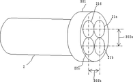
図7は本発明の受信手段の構成例を示す斜視図であり、2は受信手段、21a、21b、21c、21dは指向性アンテナ、301はレドーム、302a、302bは指向性アンテナの間隔である。
受信手段2は片手で握りやすい筒状あるいは取っ手付き筐体あるいは携帯に便利な構造に収納されており、前面に設けられたレドーム301の中に指向性アンテナ21a〜21dが収納されており、当該指向性アンテナ21a〜21dは同一方向に指向しておりアンテナ切替合成器で切替えられあるいは合成され受信手段2に内蔵されている受信機に接続されている。
指向性アンテナ21a、21dと指向性アンテナ21b、21cとの間の長さ302aと指向性アンテナ21a、21bと指向性アンテナ21c、21dとの間の長さ302bは例えば当該受信手段が受信する高周波信号の搬送波の4分の1の長さ程度に設定されている。
当該指向性アンテナ21a〜21dの指向性の方向を付近に存在する発信手段の方向に向けると、当該指向性アンテナ21a〜21dの中心線が当該発信手段の方向と一致している時は各指向性アンテナに入力する当該高周波信号の搬送波の位相は完全に一致しておりこれらの指向性アンテナを切替えて受信した高周波信号の搬送波の位相差は僅少であるが、当該中心線が当該発信手段の方向からづれると当該指向性アンテナを切替えた際の当該搬送波の位相差が大きくなる。
例えば、当該中心線が当該発信手段の方向から左右にずれると、指向性アンテナ21aと21bとの間と指向性アンテナ21cと21dとの間の当該搬送波の位相差は僅少であるが、指向性アンテナ21aと21dとの間と指向性アンテナ21bと21cの間の当該搬送波の位相差は大きくなる。4基の指向性アンテナの間隔は当該高周波信号の4分の1波長に設定されているので、当該中心線の方向が当該発信手段の方向から左右に±90°づれたとき当該搬送波の位相差が±90°づれることになる。
逆に、当該中心線が当該発信手段の方向から上下にずれると、指向性アンテナ21aと21dとの間と指向性アンテナ21bと21cとの間の当該搬送波の位相差は僅少であるが、指向性アンテナ21aと21bとの間と指向性アンテナ21cと21dの間の当該搬送波の位相差は大きくなる。4基の指向性アンテナの間隔は当該高周波信号の4分の1波長に設定されているので、当該中心線の方向が当該発信手段の方向から上下に±90°づれたとき当該搬送波の位相差が±90°づれることになる。
なお、方位を精度良く検知する為には当該受信手段2のアンテナ32aと32bの間のアイソレーションを高めることで測定の精度を高められることが実験で確かめられている。
一方、対角線上にある指向性アンテナ21aと21cとの間と指向性アンテナ21bと21dとの間では左右あるいは上下の何れの方向にづれても当該搬送波の位相差が大きくづれることになる。
当該高周波信号の搬送波の位相差を測定するとき位相差が±90°を越えると当該中心線の方向を特定するのが難しくなるのでこの範囲を越えないことが条件となるが、上記のように配列すると当該搬送波が後ろ方向から到来しない限りこの範囲を越えることはない。当該搬送波が後ろ方向から到来する場合には、地磁気センサなどを補助的に用いて判定することが可能である。
本発明の受信手段を方向者が懐中電灯を照らす要領で前方をサーチすると、発信手段が存在する方向が精度よく測定できるので、当該発信手段のアンテナの指向性を安全な歩道に沿って指向させれば、歩行者が当該発信手段の指向性の方向に沿って当該発信手段の方向に正確に歩行できるので、安全な歩行が確保できることになる。
以上の説明では4基の指向性アンテナを用いるとしたが、2基以上の任意の組合せで目的に応じた受信手段が実現できる。特に、当該指向性アンテナの間隔を当該搬送波の波長の4分の1より大きくして例えば2分の1波長とすると、当該中心線の方向と当該発信手段の方向が±30°づれると、当該搬送波の位相差が±90°になることから更に高精度の測定が可能となる。
ここで、高周波信号の搬送波の周波数として2.4GHz帯を用いると、指向性アンテナ4基を装着するときでもレドームの直径が6cm程度となり、大型の懐中電灯と同程度の大きさとなるので、歩行者が携帯して利用でき利便性が大なる歩行者支援のための装置が実現できる。
また、当該受信手段2に発信手段への発信要求信号を発信する手段を搭載することで当該発信手段を常時待ち受け状態にできるので、電波の有効利用を図ると共に、当該発信手段の電力消費を低減し太陽電池などによって駆動することが可能となる。
また、当該受信手段2に重力センサーを組込み指向性アンテナの内左右方向に位置するものと上下方向にあるものとを識別することで当該受信手段を携帯する際に余分な注意を省略できるメリットがでる。
また、当該受信手段2の複数のアンテナを位相合成しアンテナの指向性を制御して当該発信手段を方向をサーチすることで取扱あるいは操作を容易にすることが可能となる。
また、当該受信手段2に複数のアンテナを設ける代わりに、発信手段側に複数のアンテナを設けアンテナ切換合成器により切換えて高周波信号を発信し、当該受信手段2において単一あるいは複数のアンテナを用いて受信することによって発信手段側の複数のアンテナ間で高周波信号の位相差を測定することによって当該発信手段が設置された方向を検知することも可能である。
また、当該受信手段2の複数のアンテナを切替える際に切替順序を常に21aから順に21dまで一方向に切替える代わりに21dから順に21aまで逆方向に切替えることを交互に行い検出した位相差を差し引くことで、基準発振器の周波数変化あるいは回路の伝達時間あるいは伝達位相の変化等によって生じる基礎的な誤差を削除することができる。
また、当該発信手段のアンテナが歩道に沿って設置されあるいは横断歩道の安全地帯に設置された場合に、右側が危険で左側が安全であれば右側通行が可能であると判断して誘導することで視覚障害者でも安全に歩行が可能となる。
また、当該受信手段2に設けられあるいは接続された表示装置あるいは音声装置において予め設定された基準方向を当該受信手段2を所持しあるいは設置された移動主体が現在向いている方向とし当該移動主体が目的として進行すべき方向を表示しあるいは指し示しあるいはアナウンスすることによって当該移動主体が方向転換を容易にすることができる。
また、当該受信手段2をヘッドランプ状に頭に装着しあるいは胸のベストに装着することでハンドフリーな使用が可能となる。
また、当該受信手段2のアンテナを2個並べると、2.4GHzの場合、幅が3cm、長さが6cm程度となりめがねの大きさ程度となるので左右方向の検知にはめがね状に装着することも可能である。
FIG. 7 is a perspective view showing an example of the configuration of the receiving means of the present invention. 2 is a receiving means, 21a, 21b, 21c and 21d are directional antennas, 301 is a radome, and 302a and 302b are intervals of the directional antennas. .
The receiving means 2 is housed in a cylindrical shape that is easy to hold with one hand, a housing with a handle, or a structure convenient for carrying, and
The
When the directivity direction of the
For example, when the center line is shifted left and right from the direction of the transmitting means, the phase difference of the carrier wave between the
On the contrary, if the center line deviates up and down from the direction of the transmitting means, the phase difference of the carrier wave between the
In order to detect the azimuth with high accuracy, it has been confirmed through experiments that the measurement accuracy can be increased by increasing the isolation between the
On the other hand, between the
When measuring the phase difference of the carrier wave of the high-frequency signal, if the phase difference exceeds ± 90 °, it becomes difficult to specify the direction of the center line, so it is necessary not to exceed this range. When arranged, this range does not exceed this range unless the carrier wave comes from behind. When the carrier wave comes from behind, it can be determined using a geomagnetic sensor or the like as an auxiliary.
When the direction of the receiving means of the present invention is searched forward in the manner that a direction person illuminates the flashlight, the direction in which the transmitting means is present can be measured with high accuracy, so that the directivity of the antenna of the transmitting means is directed along a safe sidewalk. Then, since a pedestrian can walk accurately in the direction of the said transmission means along the direction of the directivity of the said transmission means, a safe walk can be ensured.
In the above description, four directional antennas are used. However, receiving means according to the purpose can be realized by any combination of two or more. In particular, when the interval between the directional antennas is larger than a quarter of the wavelength of the carrier wave and is, for example, a half wavelength, when the direction of the center line and the direction of the transmitting unit are shifted by ± 30 °, Since the phase difference of the carrier wave is ± 90 °, it is possible to measure with higher accuracy.
Here, if the 2.4 GHz band is used as the frequency of the carrier wave of the high-frequency signal, the diameter of the radome will be about 6 cm even when four directional antennas are attached, and it will be the same size as a large flashlight. A device for supporting pedestrians that can be carried and used by a person with great convenience can be realized.
In addition, since the receiving means 2 is equipped with a means for transmitting a transmission request signal to the transmitting means, the transmitting means can be kept in a standby state at all times, so that radio waves can be used effectively and power consumption of the transmitting means can be reduced. It can be driven by a solar cell or the like.
In addition, a gravitational sensor is incorporated in the receiving means 2, and by distinguishing between a directional antenna located in the left and right direction and an up and down direction, there is an advantage that extra care can be omitted when carrying the receiving means. Out.
In addition, it is possible to facilitate handling or operation by phase-combining a plurality of antennas of the receiving means 2 and controlling the directivity of the antennas to search the transmitting means for directions.
Further, instead of providing a plurality of antennas in the receiving means 2, a plurality of antennas are provided on the transmitting means side, and a high-frequency signal is transmitted by switching with an antenna switching synthesizer, and the receiving means 2 uses a single or a plurality of antennas. It is also possible to detect the direction in which the transmitting means is installed by measuring the phase difference of the high-frequency signal between the plurality of antennas on the transmitting means side.
Further, when switching the plurality of antennas of the receiving means 2, instead of always switching the switching order from 21a to 21d in one direction, alternately switching from 21d to 21a in the reverse direction and subtracting the detected phase difference. Thus, a basic error caused by a change in the frequency of the reference oscillator or a change in the transmission time or transmission phase of the circuit can be eliminated.
In addition, when the antenna of the transmission means is installed along the sidewalk or in the safety zone of the pedestrian crossing, if the right side is dangerous and the left side is safe, it should be determined that the right-hand traffic is possible So visually impaired people can safely walk.
Further, a reference direction preset in a display device or audio device provided or connected to the receiving means 2 is set as a direction in which the moving subject possessing or installing the receiving means 2 is currently facing. The moving subject can easily change the direction by displaying, pointing, or announcing the direction to be traveled for the purpose.
Further, the receiving means 2 can be used in a hand-free manner by being mounted on the head in the form of a headlamp or mounted on the chest vest.
In addition, when two antennas of the receiving means 2 are arranged, in the case of 2.4 GHz, the width is about 3 cm and the length is about 6 cm, which is about the size of glasses. Is also possible.
図8は本発明のアンテナ切替合成器の他の実施例を示す構成図であり、21a、21bはアンテナ素子、22はアンテナ切替合成器、223a、223bは遅延回路、224a、224bはサーキュレータ、225はアンテナスイッチ、226は2分岐器、227は相関器(N−1)、228a、228b、228cは接続端子である。ここで、アンテナ21aと21bの間は高周波信号の搬送波の波長のλ/4とする。
本アンテナ切替合成器22は、中継手段あるいはパッシブタグに対応するものであり、接続端子228aには発信手段が接続され、例えば、2.4GHz帯でスペクトル拡散符号(N)により拡散された高周波信号が印加されている。当該高周波信号は、2分岐器226により2分岐され、サーキュレータ224a、224bを経由して、大部分は遅延回路223a、223bで遅延されアンテナ21a、21bから空間に放射されるが、一部はアンテナスイッチ225に回り込んでいる。
一方、アンテナ21a、21bで受信された高周波信号は、遅延線223a、223bで遅延されサーキュレータ224a、224bを経由してアンテナスイッチ225により切替えられ、3分岐器226bにより3分岐され各々相関器227a、227b、227cにより接続端子228e、228f、228gから入力されるスペクトル拡散符号との相関がとられ、接続端子228b、228c、228dから出力されている。
接続端子228aに印加された高周波信号(PdBm)の一部がアンテナスイッチ225に回込む電力は、P−3dB−20dB=P−23dB程度である。更に、相関器227aは接続端子228aに印加されたペクトル拡散符号(N−1)との相関をとるように設けられており、当該回り込む高周波信号はスペクトル拡散符号(N)により拡散されているので、相関器227aはスペクトル拡散符号(N)と(N−1)との相関をとることになり、当該回り込む高周波信号は10log(W1/W2)dBの改善される。
ここで、Pは接続端子228aに印加された高周波信号の電力であり10mWとし、W1は発信手段のスペクトル拡散帯域であり50MHzとし、W2は受信手段の中間周波信号の帯域幅で10Hzとすると、接続端子228bに回り込む高周波信号の電力は、10dBm−23dB−10log(50MHz/10Hz)=−80dBmとなる。
遅延線223a、223bは、当該高周波信号がアンテナ21a、21bから空間に放射され中継手段により中継されて再度アンテナ21a、21bで受信されサーキュレータ224a、224bに到達した時に、スペクトル拡散符号(N)が(N−1)にまで遅れるようにするためのものであり、スペクトル拡散符号の1/2チップ分の遅延量が最低限必要である。
中継手段が折返し中継の際に20dBの増幅度があるとし、発信手段と受信手段のアンテナ21a、21bの利得が発信時14dBi、受信時9dBi、中継手段のアンテナ利得が受信時と発信時ともに11dBi、受信手段の最低入力レベルをー60dBmとすると、片道の許容損失は約69dBとなり、当該発信手段と中継手段との間の間隔は約36mが許容される。
なお、遅延回路223a、223bによる遅延量は、スペクトル拡散符号の伝送速度を50Mbpsとすると、20nsecの半分の10nsec以上が必要である。
また、接続端子228aには無変調の高周波信号を印加し中継手段でスペクトル拡散を行い折り返しても同様な効果がえ得られるが、この場合には、遅延回路223a、223bは不要である。
また、接続端子228aを複数の接続端子とし各々に異なるスペクトル拡散符号により拡散された高周波信号を印加し2分岐器226を削除してサーキュレータ224aと224bに接続し、相関器(N−1)227のスペクトル拡散符号をアンテナスイッチ225と連動させて当該発信手段側の2種類のスペクトル拡散符号に切替えることで同様な効果が得られる。
FIG. 8 is a block diagram showing another embodiment of the antenna switching synthesizer of the present invention, in which 21a and 21b are antenna elements, 22 is an antenna switching synthesizer, 223a and 223b are delay circuits, 224a and 224b are circulators, 225 Is an antenna switch, 226 is a bifurcater, 227 is a correlator (N-1), 228a, 228b, and 228c are connection terminals. Here, the distance between the
This
On the other hand, the high frequency signals received by the
The power that a part of the high-frequency signal (PdBm) applied to the
Here, P is the power of the high frequency signal applied to the
The
Assume that the relay means has an amplification factor of 20 dB when looping back, the gain of the
Note that the delay amount by the
Further, the same effect can be obtained by applying a non-modulated high-frequency signal to the
In addition, the
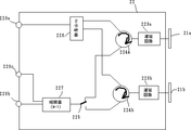
図9は本発明の中継手段の実施例を示す構成図であり、1は中継手段、11a、11bは指向性アンテナ、121は帯域通過フイルタ、122は変調器、123は信号発生器、124は増幅器、105はバッテリー、106は太陽電池、107は発光体、108a、108bは指向性パターンである。
中継手段1は発信手段の一つの形態であり受信した高周波信号を変調し増幅して再発信する。当該中継手段1は、指向性アンテナ11b、帯域通過フイルタ121、変調器122、信号発生器123、増幅器124および指向性アンテナ11aから構成されている。
指向性アンテナ11aと11bは、例えば、お互いに逆旋回の円偏波指向性アンテナであり必要な結合損が得られるように間隔を空けて設けられており、放射パターン108aと108bは通常平行する方向に向けられている。
当該指向性アンテナ11bの出力端子は帯域通過フイルタ121により帯域が制限されて変調器122に接続されており、当該変調器122において信号発生器123により生成されたスペクトル拡散符号により拡散された副搬送波によって両側帯波変調され、当該変調器122の出力は増幅器124により増幅されて指向性アンテナ11aから再発信される。
変調器122は例えばダブルバランスミキサーを用いた両側帯波変調器であり、スペクトル拡散された副搬送波を印加すると、中心周波数の両側に副搬送波の周波数だけ離れスペクトル拡散された高周波信号が生成される。この両側に現れる二つの高周波信号の関係はお互いに直交関係にあり、この関係により当該中継手段1と受信手段との距離が検知できることになる。なお、当該変調器122の変調方式は両側帯波変調に限らず直交している複数の搬送波が生成できる方式であれば良く、受信した高周波信号がすでに直交している複数の搬送波を含んでいれば任意の変調方式で良い。
当該中継手段1に受信機と制御器を組込み外部の発信手段あるいは携帯電話機などから受信した信号により起動させあるいは間欠動作させることで、常時動作状態にするのに比較して電力の消費を削減することができる。
当該指向性アンテナ11aから変調された高周波信号を再発信するとその一部は空間で結合して指向性アンテナ11bにより受信される。変調器122を両側帯波変調すると当該帯域通過フイルタ121の通過帯域幅の外に追いやることができ帯域通過フイルタ121により大部分が阻止されるので、増幅器124の利得が当該帯域通過フイルタ121の減衰量より少ない限り相互干渉あるいは寄生発振などを防止することができる。
指向性アンテナ11aと11bの利得をそれぞれG1dBとし、両者間の結合損をL0dBとし、指向性アンテナ11aから発信される高周波信号の変調後の帯域幅をW1(MHz)とし帯域通過フイルタ121の帯域幅をW2(MHz)とするといわゆるプロセス利得PGは、PG=10×log(W1/W2)dBとなり、増幅器124の利得をG2dBとすると、当該指向性アンテナ11aから発信した高周波信号が指向性アンテナ11bに回り込む割合即ち結合損Lは、L=L0+10×log(W2/W1)+S (dB)となる。ここで、Sは右旋回と左旋回の指向性アンテナ11aと11bとの間の結合損であり10dB程度が確保できる。
指向性アンテナ11aと11bの間隔を半波長程度とするとL0=22dBとなり、プロセス利得をPG=W1/W2=100=20dBとし、右旋回と左旋回のアンテナ間の結合損が10dB程度とすると、L=22+20+10=52dBとなるので、増幅器124の利得として47dB程度が確保できる。
携帯端末が発信する高周波電力が当該中継手段1により折り返されて再び携帯端末で受信されるまでの伝送損失Tは、T=2×20×log(D/λ)ー2G1ーG2となる。ここで、D=携帯端末と当該中継手段1との間の距離であり2.4GHz帯で距離が24mの時約68dBとなることから、T=2×68−2×9dBー47dB=71dBとなり、この値は丁度片道の伝送損失68dBとほぼ同じであることから、あたかも当該中継手段1が自ら高周波信号を発信した場合と等価になる。
一方、太陽電池106により発電された電力はバッテリー105に蓄電され各部に電力を供給し、発光体107は夜間に当該中継手段1の存在を示しあるいは変調器122が起動されたこと等を示すために間欠点灯させる他は、発信手段と同様な効果が得られる。
また、当該変調器122において、スペクトル拡散された副搬送波信号を用いて振幅変調あるいは両側帯波変調を行なうことでスペクトル拡散された直交する複数の搬送波を有する高周波信号を出力でき、当該中継手段と受信手段の間の距離の検知が可能となる。両側帯波変調器として当該高周波信号の周波数帯域で直接動作するダブルバランスミキサーを用いることで回路が単純化できる。
また、当該増幅器124の出力の1部を直接帯域通過フイルタ121の入力に可変移相器および可変減衰器を介して結合し、当該指向性アンテナ11aの出力が指向性アンテナ11bに直接回りこみ干渉する程度を監視し、当該移相器の位相を制御して回り込みをキャンセルすることもできる。
また、当該信号発生器123において生成する変調信号あるいは副搬送波あるいはスペクトル拡散符号に当該中継手段1の識別番号あるいは識別符号あるいはデータを含めることが可能であり、あるいは当該中継手段1の遅れ時間をデータとして含むことができる。
また、当該中継手段1を広帯域のストレートアンプとし、当該増幅器の増幅度を当該指向性アンテナ11aと11b間のアイソレーションより小さく設定することで、遅延時間が限りなく小さくできる。
FIG. 9 is a block diagram showing an embodiment of the relay means of the present invention, wherein 1 is a relay means, 11a and 11b are directional antennas, 121 is a band pass filter, 122 is a modulator, 123 is a signal generator, and 124 is An amplifier, 105 is a battery, 106 is a solar cell, 107 is a light emitter, and 108a and 108b are directivity patterns.
The
The
The output terminal of the
The
Incorporating a receiver and a controller in the relay means 1 and starting up or intermittently operating with a signal received from an external transmission means or a mobile phone, etc., thereby reducing the power consumption compared to the case of always operating. be able to.
When the high-frequency signal modulated from the
The gain of each of the
If the interval between the
The transmission loss T until the high frequency power transmitted from the portable terminal is returned by the relay means 1 and received again by the portable terminal is T = 2 × 20 × log (D / λ) −2G1−G2. Here, D = distance between the portable terminal and the relay means 1 and about 68 dB when the distance is 24 m in the 2.4 GHz band, so T = 2 × 68−2 × 9 dB−47 dB = 71 dB. Since this value is almost the same as the one-way transmission loss 68 dB, it is equivalent to the case where the relay means 1 itself transmits a high-frequency signal.
On the other hand, the electric power generated by the
Further, the
Further, a part of the output of the
Further, the identification number, identification code or data of the relay means 1 can be included in the modulation signal or subcarrier or spread spectrum code generated by the
Further, by setting the relay means 1 as a wide-band straight amplifier and setting the amplification degree of the amplifier smaller than the isolation between the
以上の説明では、数値制御発振器を用いるよう説明しているがデジタルPLL回路を用いるなど等価な方法によっても同様な効果が得られる。
また、自己相関器としてデジタル方式について説明したが、アナログ方式を用いても同様な効果が得られる。
また、当該発信手段から超音波トランスデューサーあるいは超音波送波器を用いて超音波信号を発信し、当該受信手段において超音波トランスデューサーあるいは超音波受波器を用いて超音波信号を受信し、あるいは当該発信手段において発光ダイオードあるいはレーザーダイオードを用いて光信号を発信し当該受信手段においてホトダイオードを用いて光信号を受信することでも同様な効果が得られる。なお、本出願では、超音波トランスデューサーあるいは超音波送受波器と発光ダイオードあるいはレーザーダイオードあるいはホトダイオードを総称して送受波器と呼称するものとする。
また、スペクトル拡散を行なわず無変調あるいはアナログ信号あるいはデジタル信号により変調された高周波信号の搬送波の位相差を複数のアンテナを切替えて測定することでも同様な効果が得られる。
また、当該発信手段あるいは中継手段においてスペクトル拡散符号を超音波信号あるいは高周波信号あるいは光信号に直接変換して発信しても同様な効果が得られる。
また、複数のアンテナを切替える代わりに、複数のアンテナに対応する受信手段を個別に設けて受信手段間の位相差を測定することでも同様な効果が得られる。
また、当該携帯端末の周辺に歩行者等の障害物が存在するとアクテイブタグからの発信される超音波信号あるいは高周波信号あるいは光信号が遮蔽される場合がありあるいは反射されてマルチパスによる誤差の原因になるので、アクテイブタグに指向性が鋭い指向性アンテナを用い比較的に高い位置に設置し上方より吹き降ろす形指向性を向けることが望ましい。
また、複数のアンテナあるいは送受波器がケーブルにより直列あるいは並列に接続されあるいは漏洩ケーブルを構成し歩行者あるいは移動体の進行方向に沿って設置しあるいは特定エリアの周辺部に設置することで進行方向の誘導あるいは特定エリアのガイダンスを効果的に行うことができる。
また、当該発信手段において生成した光信号を当該高周波信号を副搬送波として変調し空間に放射し当該受信手段において受信した光信号から当該高周波信号を復調することで方向と距離が検知できる。
また、当該発信手段を太陽電池と蓄電用コンデンサとの一体構造とし薄型構造の防水筐体に収納することで道路表面に埋設しあるいは輸送物体の表面に貼付けることが長時間の連続運用ができる。
また、当該各手段が衛星を含む飛行物体あるいは自動車あるいは歩行者あるいはロボットを含む移動物体に搭載されあるいは装着されあるいは携帯されても同様な効果が得られる。
また、当該複数のアンテナを切替合成器により少なくとも2群に分けて出力し当該2群間の相関を求めることでも同様な効果が得られる。
また、当該受信手段あるいは発信手段あるいは中継手段あるいはこれらの任意の組合わせが複数のアンテナを有する場合、一つの手段の複数のアンテナが切替られる場合に他の手段の複数のアンテナを固定することで方向あるいは距離の検知を容易にしあるいは検知精度を維持できる。
また、当該発信手段が衝撃により発電する素子等とともにゴルフあるいは野球などの球技用ボールに組込むことで打球時あるいは蹴球時の衝撃で高周波信号の発信を起動し当該ボールの軌跡を正確に追跡することができる。
また、当該発信手段のアンテナが球形あるいは楕円球形であり内部に回路部品を組込むことで不要な高周波信号が外部に漏洩するのを抑制できる構造となる。
また、当該発信手段あるいは中継手段において商用電源から電磁誘導により供給される電力あるいは電子レンジあるいは発振器などから放射される2.4GHz帯の高周波電力あるいは外部から加えられる振動あるいは衝撃のエネルギにより蓄電用コンデンサあるいは電池を充電することで連続運転が可能となる。
In the above description, the numerically controlled oscillator is used, but the same effect can be obtained by an equivalent method such as using a digital PLL circuit.
Although the digital method has been described as the autocorrelator, the same effect can be obtained even if the analog method is used.
Further, an ultrasonic signal is transmitted from the transmitting means using an ultrasonic transducer or an ultrasonic transmitter, and an ultrasonic signal is received using an ultrasonic transducer or an ultrasonic receiver in the receiving means, Alternatively, a similar effect can be obtained by transmitting an optical signal using a light emitting diode or a laser diode in the transmitting means and receiving an optical signal using a photodiode in the receiving means. In the present application, the ultrasonic transducer or ultrasonic transducer and the light emitting diode, laser diode or photodiode are collectively referred to as a transducer.
Further, the same effect can be obtained by measuring the phase difference of the carrier wave of the high-frequency signal that is not modulated or modulated by the analog signal or the digital signal without performing the spread spectrum.
The same effect can be obtained by directly converting the spread spectrum code into an ultrasonic signal, a high-frequency signal, or an optical signal in the transmitting means or relay means.
Further, instead of switching a plurality of antennas, the same effect can be obtained by separately providing receiving means corresponding to the plurality of antennas and measuring the phase difference between the receiving means.
In addition, if there are obstacles such as pedestrians around the mobile terminal, the ultrasonic signal, high-frequency signal or optical signal transmitted from the active tag may be blocked or reflected to cause an error due to multipath. Therefore, it is desirable to use a directional antenna with a sharp directivity for the active tag and to set the directivity so that it is installed at a relatively high position and blows down from above.
In addition, multiple antennas or transducers are connected in series or in parallel by cables, or constitute a leaky cable, installed along the direction of travel of pedestrians or moving objects, or installed in the periphery of specific areas. Guidance or specific area guidance can be effectively performed.
Further, the direction and distance can be detected by modulating the high-frequency signal generated by the transmitting means as a subcarrier and radiating it to the space, and demodulating the high-frequency signal from the optical signal received by the receiving means.
In addition, the transmitting means can be integrated with a solar cell and a capacitor for storage and housed in a thin waterproof case so that it can be embedded in the road surface or pasted on the surface of a transported object for a long time. .
The same effect can be obtained even if each means is mounted on, mounted on, or carried by a flying object including a satellite or a moving object including an automobile, a pedestrian, or a robot.
A similar effect can also be obtained by outputting the plurality of antennas divided into at least two groups by a switching synthesizer and obtaining the correlation between the two groups.
In addition, when the receiving means, the transmitting means, the relay means, or any combination thereof has a plurality of antennas, when a plurality of antennas of one means are switched, a plurality of antennas of other means can be fixed. The direction or distance can be easily detected or the detection accuracy can be maintained.
In addition, when the transmitting means is incorporated into a ball for ball games such as golf or baseball together with an element that generates electric power by impact, the high-frequency signal is transmitted by impact at the time of hitting or kicking, and the trajectory of the ball is accurately tracked. Can do.
Further, the antenna of the transmitting means has a spherical shape or an elliptical spherical shape, and it is possible to suppress leakage of unnecessary high-frequency signals to the outside by incorporating circuit components therein.
Further, in the transmitting means or the relay means, electric power supplied by electromagnetic induction from a commercial power supply, high frequency power of 2.4 GHz band radiated from a microwave oven or an oscillator, etc., or energy of vibration or impact applied from the outside is stored. Alternatively, continuous operation is possible by charging the battery.
1 発信手段
2 受信手段
11、11a、11b 指向性アンテナ
21a、21b、21c、21d 指向性アンテナ
22、22a アンテナ切替合成器
23 受信機
24 信号検出制御部
25 操作表示部
31、 発信手段1のアンテナの指向性パターン
31a、31b 発信手段1から受信手段2のアンテナ21aと21bおよび21cと21dへ向けた方向線
31c、31d、31e 発信手段1から反射物41bへおよび反射物41bから受信手段2のアンテナ21aと21bおよび21cと21dへ向けた方向線
32a、32b、31c、31d アンテナ21aと21bおよび21cと21dの指向性
33a 指向性31の延長線
33b、33c、33d、33e 引出線
34a、34b、34c、34d 寸法線
41a 遮蔽物
41b 反射物
42a 反射物から発信手段1を仰ぐ角度
42b 受信手段2から反射物41bを仰ぐ角度
51 発信手段が生成するスペルトル拡散符号
52 シフトレジスタ
53 1周期分の固定相関器
54 ΣSin積和演算器
55 ΣCos積和演算器
56 発信手段と受信手段の間の遅延時間
57 振幅スペクトル検出器
58 位相スペクトル検出器
59、60 接続端子
61 アナログデジタル変換器
62 信号検出器
63 基準発振器
101 アンテナスイッチ
102 送信機
103 受信機
104 制御部
105 バッテリー
106 太陽電池
107 発光ダイオード
108、108a、108b 指向性パターン
121 帯域通過フイルタ
122 変調器
123 信号発生器
124 増幅器
201、202、203 接続端子
223a、223b 遅延回路
224a、224b サーキュレータ
225 アンテナスイッチ
226 分岐器
227 相関器(N−1)
228a、228b、228c 接続端子
301 アンテナ用レドーム
302a、302b アンテナ間隔
DESCRIPTION OF SYMBOLS 1 Transmission means 2 Reception means 11, 11a, 11b Directional antenna 21a, 21b, 21c, 21d Directional antenna 22, 22a Antenna switching combiner 23 Receiver 24 Signal detection control part 25 Operation display part 31, Antenna of transmission means 1 Directivity patterns 31a, 31b Direction lines 31c, 31d, 31e from the transmitting means 1 to the antennas 21a and 21b and 21c and 21d of the receiving means 2 from the transmitting means 1 to the reflector 41b and from the reflector 41b to the receiving means 2 Directional lines 32a, 32b, 31c, 31d toward antennas 21a and 21b and 21c and 21d Antennas 21a and 21b and directivity 33a of 21c and 21d Extension lines 33b, 33c, 33d and 33e of directivity 31 Lead lines 34a and 34b , 34c, 34d Dimension line 41a Shield 41b Reflector 42a Angle 42b at which the transmitting means 1 is looked up from the projectile 51 Angle at which the reflecting means 41b is looked up from the receiving means 2 Spelltle spread code 52 generated by the transmitting means Shift register 53 Fixed correlator 54 for one period ΣSin product-sum calculator 55 ΣCos product-sum Operation unit 56 Delay time 57 between transmission means and reception means 57 Amplitude spectrum detector 58 Phase spectrum detector 59, 60 Connection terminal 61 Analog-digital converter 62 Signal detector 63 Reference oscillator 101 Antenna switch 102 Transmitter 103 Receiver 104 Control unit 105 Battery 106 Solar cell 107 Light-emitting diode 108, 108a, 108b Directional pattern 121 Band pass filter 122 Modulator 123 Signal generator 124 Amplifier 201, 202, 203 Connection terminal 223a, 223b Delay circuit 224a, 224b Circular 225 Antenna switch 226 Branch 227 Correlator (N-1)
228a, 228b,
Claims (19)
超音波信号あるいは高周波信号あるいは光信号を発信するための発信手段と、当該発信手段から発信された超音波信号あるいは高周波信号あるいは光信号を受信するための受信手段から構成され、
前記発信手段と受信手段の少なくともいずれか一方が移動体に装着されあるいは移動体によって携帯され、
当該発信手段が発信する信号が少なくとも当該発信手段を識別するための識別用信号と測定のための測定用信号から構成され、
前記測定用信号は、同期しかつ/あるいは直交する、周波数が異なる複数の搬送波信号あるいは複数の副搬送波信号あるいは複数の側帯波信号あるいは複数の変調信号あるいは複数の拡散符号あるいはこれらの組み合わせから構成され、
前記発信手段は、前記測定用信号を同時あるいは順次に発信し、
前記発信手段あるいは受信手段あるいはこれらの両方が、前記測定用信号の搬送波信号あるいは副搬送波信号の1波長以下の間隔で配置された複数のアンテナあるいは複数の送受波器と、当該複数のアンテナあるいは複数の送受波器を周期的に切替えおよび/あるいは組み合わせを変えるための切替合成器を有し、
前記受信手段が前記発信手段から発信される測定用信号から搬送波信号あるいは副搬送波信号あるいは側帯波信号あるいは変調信号あるいは拡散符号を抽出するための受信機と、当該受信機の出力信号を基準発振器に同期してデジタル信号に変換し当該デジタル信号を処理するための信号検出器を有し、
当該信号検出器において、上記識別用信号を処理して当該発信手段を識別し、上記測定用信号を処理して当該複数のアンテナあるいは複数の送受波器に対応した搬送波信号あるいは副搬送波信号の少なくとも周波数および/あるいは位相を検出し、当該検出結果から当該発信手段が位置する方向あるいは当該受信手段が向かっている方向を検知すると共に、前記測定用信号の同期しかつ/あるいは直交する複数の搬送波信号あるいは副搬送波信号あるいは複数の変調信号あるいは複数の拡散符号あるいはこれらの組み合わせに対応した少なくとも周波数および/あるいは位相を検出し、当該検出結果から、前記発信手段から前記受信手段までの距離を検知することを特徴とするアクテイブタグ装置。 In a moving body detection system using an ultrasonic signal, a high-frequency signal, or an optical signal,
The transmitting means for transmitting an ultrasonic signal, a high frequency signal or an optical signal, and a receiving means for receiving an ultrasonic signal, a high frequency signal or an optical signal transmitted from the transmitting means,
At least one of the transmitting means and the receiving means is attached to or carried by a moving body,
The signal transmitted by the transmission means is composed of at least an identification signal for identifying the transmission means and a measurement signal for measurement,
The measurement signal is composed of a plurality of carrier signals, a plurality of subcarrier signals, a plurality of sideband signals, a plurality of modulation signals, a plurality of spreading codes, or a combination thereof, which are synchronized and / or orthogonal, and have different frequencies. ,
The transmission means transmits the measurement signals simultaneously or sequentially,
Said transmitting means or the receiving means or both of them, and a plurality of antennas or a plurality of transducer arranged at intervals of less than one wavelength of the carrier signal or subcarrier signal of the measurement signals, the plurality of antennas or a plurality A switching synthesizer for periodically switching and / or changing the combination of
A carrier signal or subcarrier signal or sideband signal or a receiver for extracting the modulated signal or the spread code from the measuring signal the receiving means is transmitted from said transmitting means, the reference oscillator output signal of the receiver Having a signal detector for synchronously converting to a digital signal and processing the digital signal;
In the signal detector, the identification signal is processed to identify the transmitting means, and the measurement signal is processed to process at least a carrier signal or a subcarrier signal corresponding to the plurality of antennas or the plurality of transducers. detects the frequency and / or phase, the detection result together with the transmitting means detects a direction in which towards the direction or the reception means located from a plurality of carrier signals to be synchronized and / or perpendicular of the measurement signal Alternatively, at least the frequency and / or phase corresponding to the subcarrier signal, the plurality of modulation signals, the plurality of spreading codes, or a combination thereof is detected, and the distance from the transmitting unit to the receiving unit is detected from the detection result. Active tag device characterized by.
前記スペクトル拡散符号が少なくとも短時間に同期を確立するための短周期の符号系列と測定を行なうための比較的に長周期の符号系列あるいは短周期の符号系列の繰返しから構成されおよび/あるいは当該測定用信号の一部あるいは全部が無変調の搬送波信号あるいは副搬送波信号で代替されており、
前記受信手段において、生成されたスペクトル拡散符号により逆拡散しあるいはN乗あるいはN逓倍を行うことによって、当該測定用信号から少なくとも搬送波信号あるいは副搬送波信号を抽出することを特徴とする請求項第1項に記載のアクテイブタグ装置。 In the transmission means, the carrier signal or subcarrier signal is spread by a spread spectrum code to generate the measurement signal,
The spread spectrum code is composed of a short-cycle code sequence for establishing synchronization in at least a short time and a relatively long-cycle code sequence for measurement or a repetition of a short-cycle code sequence and / or the measurement. Part or all of the signal is replaced with an unmodulated carrier signal or subcarrier signal,
2. The receiver according to claim 1, wherein at least a carrier signal or a subcarrier signal is extracted from the measurement signal by despreading the generated spread spectrum code or performing Nth power or N multiplication. The active tag device according to item.
は高周波信号あるいは光信号を受信するための受信手段と、当該受信手段により受信した信号を直接あるいは必要な変換あるいは必要な変調を行ないあるいはスペクトル拡散して再発信しあるいは中継するための中継手段を有し、
前記中継手段において、前記発信手段を識別するための識別用信号と測定のための測定用信号を生成することを特徴とする請求項第1項に記載のアクテイブタグ装置。 The transmitting unit receives an ultrasonic signal, a high-frequency signal or an optical signal transmitted from a second transmitting unit other than the transmitting unit, and a direct or necessary conversion of the signal received by the receiving unit. Or having a relay means for performing necessary modulation or re-spreading or relaying with spread spectrum,
In the relay unit, Akuteibu tag device of claim 1 wherein, wherein generating a measurement signal for measurement and identification signals for identifying the calling unit.
前記発信手段が交通信号に関する報知情報および/あるいは当該エリアに関する報知情
報を発信することを特徴とする請求項第1項に記載のアクテイブタグ装置。 Along the interior and / or peripheral portions or areas of the area where the moving body is allowed to move can or it safely, a plurality of antennas or a plurality of transmission and reception waves that are connected to a plurality of said transmitting means is installed or the transmitting means A vessel is installed to assist or guide the mobile body to move along or out of the area ,
The transmission means is notification information regarding traffic signals and / or notification information regarding the area.
The active tag device according to claim 1, wherein information is transmitted .
Priority Applications (1)
| Application Number | Priority Date | Filing Date | Title |
|---|---|---|---|
| JP2004218249A JP3991081B2 (en) | 2003-07-28 | 2004-07-27 | Active tag device |
Applications Claiming Priority (11)
| Application Number | Priority Date | Filing Date | Title |
|---|---|---|---|
| JP2003280897 | 2003-07-28 | ||
| JP2003299713 | 2003-08-25 | ||
| JP2003356366 | 2003-10-16 | ||
| JP2003380662 | 2003-11-11 | ||
| JP2004004935 | 2004-01-13 | ||
| JP2004019858 | 2004-01-28 | ||
| JP2004038639 | 2004-02-16 | ||
| JP2004103965 | 2004-03-31 | ||
| JP2004140666 | 2004-05-11 | ||
| JP2004170486 | 2004-06-08 | ||
| JP2004218249A JP3991081B2 (en) | 2003-07-28 | 2004-07-27 | Active tag device |
Related Child Applications (2)
| Application Number | Title | Priority Date | Filing Date |
|---|---|---|---|
| JP2007069070A Division JP4088700B2 (en) | 2003-07-28 | 2007-03-16 | Active tag device |
| JP2007069071A Division JP2007240534A (en) | 2003-07-28 | 2007-03-16 | Active tag device |
Publications (3)
| Publication Number | Publication Date |
|---|---|
| JP2006023261A JP2006023261A (en) | 2006-01-26 |
| JP2006023261A5 JP2006023261A5 (en) | 2006-06-15 |
| JP3991081B2 true JP3991081B2 (en) | 2007-10-17 |
Family
ID=35796621
Family Applications (1)
| Application Number | Title | Priority Date | Filing Date |
|---|---|---|---|
| JP2004218249A Expired - Fee Related JP3991081B2 (en) | 2003-07-28 | 2004-07-27 | Active tag device |
Country Status (1)
| Country | Link |
|---|---|
| JP (1) | JP3991081B2 (en) |
Cited By (1)
| Publication number | Priority date | Publication date | Assignee | Title |
|---|---|---|---|---|
| WO2009063537A1 (en) * | 2007-11-12 | 2009-05-22 | Fujitsu Limited | Radio relay device, radio relay vehicle, and radio relay method |
Families Citing this family (24)
| Publication number | Priority date | Publication date | Assignee | Title |
|---|---|---|---|---|
| JP4123494B2 (en) * | 2003-07-28 | 2008-07-23 | 有限会社アール・シー・エス | Mobile object search system |
| JP2007212424A (en) * | 2006-01-10 | 2007-08-23 | Rcs:Kk | Position detecting device and position detection program |
| JP2007200072A (en) * | 2006-01-27 | 2007-08-09 | Nec Logistics Ltd | Reader, ic tag, and ic tag system using the same |
| JPWO2008029812A1 (en) * | 2006-09-05 | 2010-01-21 | 有限会社アール・シー・エス | Distance measuring device |
| JP2008298707A (en) * | 2007-06-04 | 2008-12-11 | Kobe Steel Ltd | Position detection system |
| JP4591565B2 (en) | 2008-07-14 | 2010-12-01 | ソニー株式会社 | Reception device, wireless communication system, position estimation method, and program |
| JP2010286956A (en) * | 2009-06-10 | 2010-12-24 | Chugoku Electric Power Co Inc:The | Vehicle position detection system |
| JP5683805B2 (en) * | 2009-12-04 | 2015-03-11 | 中国電力株式会社 | Positioning device |
| JP5696312B2 (en) * | 2009-12-04 | 2015-04-08 | 中国電力株式会社 | Wide area location system |
| JP2011179972A (en) * | 2010-03-01 | 2011-09-15 | Chugoku Electric Power Co Inc:The | Multiple person-arrangement confirmation support system |
| WO2012098962A1 (en) * | 2011-01-18 | 2012-07-26 | シャープ株式会社 | Coordinate input device, display device comprising coordinate input device, and coordinate input method |
| JP5516455B2 (en) * | 2011-02-23 | 2014-06-11 | トヨタ自動車株式会社 | Approaching vehicle detection device and approaching vehicle detection method |
| JP5899698B2 (en) * | 2011-08-09 | 2016-04-06 | 株式会社豊田中央研究所 | Human body part position measuring device and electronic device system |
| EP2755300A4 (en) | 2011-09-09 | 2015-04-22 | Chugoku Electric Power | Non-contact power supply system and non-contact power supply method |
| CN103875157B (en) * | 2011-10-14 | 2016-10-12 | 英派尔科技开发有限公司 | Mobile terminal, electrical power transmission system and computer-readable recording medium |
| EP2800241A4 (en) | 2011-12-27 | 2015-07-01 | Chugoku Electric Power | Contactless power supply system, power supply device, and method for controlling contactless power supply system |
| JP5116904B1 (en) | 2012-02-29 | 2013-01-09 | 中国電力株式会社 | Non-contact power supply system, power supply device, and control method for non-contact power supply system |
| JP6044921B2 (en) * | 2012-03-28 | 2016-12-14 | 国立大学法人弘前大学 | Guidance system |
| US9001621B2 (en) | 2012-04-20 | 2015-04-07 | Symbol Technologies, Inc. | Dual frequency ultrasonic locationing system |
| JP2014048049A (en) * | 2012-08-29 | 2014-03-17 | Toyota Central R&D Labs Inc | Movement detection device |
| JP2014137347A (en) * | 2013-01-18 | 2014-07-28 | Toyota Central R&D Labs Inc | Radio communication apparatus and radio communication method |
| JP5968844B2 (en) * | 2013-09-20 | 2016-08-10 | 中国電力株式会社 | Position detection system and position detection method |
| JP7090882B2 (en) * | 2018-03-09 | 2022-06-27 | 国立大学法人金沢大学 | Wave source information presentation system, wave source information presentation method, and program |
| CN112484623B (en) * | 2020-12-01 | 2022-07-15 | 中电科西北集团有限公司 | Galloping numerical value acquisition method for power transmission line |
Family Cites Families (20)
| Publication number | Priority date | Publication date | Assignee | Title |
|---|---|---|---|---|
| JPS582764A (en) * | 1981-06-30 | 1983-01-08 | Furuno Electric Co Ltd | Direction finding system using hyperbolic navigation |
| JPS60214100A (en) * | 1984-04-10 | 1985-10-26 | オムロン株式会社 | Safety guidance unit |
| JPS61209382A (en) * | 1985-03-14 | 1986-09-17 | Nec Corp | Range finder |
| JPH0771020B2 (en) * | 1986-09-16 | 1995-07-31 | ソニー株式会社 | Spread spectrum communication demodulator |
| JPH02304384A (en) * | 1989-05-19 | 1990-12-18 | Nec Corp | Azimuth measuring system |
| JPH113498A (en) * | 1997-06-13 | 1999-01-06 | Mitsubishi Electric Corp | Vehicle location detection system |
| JP3640788B2 (en) * | 1998-03-06 | 2005-04-20 | アルプス電気株式会社 | Estimation method of arrival angle of radio wave |
| DE69939251D1 (en) * | 1998-11-03 | 2008-09-18 | Nxp Bv | FUNKPEILSYSTEM |
| JP3572391B2 (en) * | 1999-08-04 | 2004-09-29 | 日産自動車株式会社 | Distance measuring device |
| JP2003078941A (en) * | 2000-07-31 | 2003-03-14 | Rcs:Kk | Position detection system |
| US6384784B1 (en) * | 2001-01-05 | 2002-05-07 | Tektronix, Inc | Direction finder system using spread spectrum techniques |
| JP2002236161A (en) * | 2001-02-06 | 2002-08-23 | Mitsubishi Electric Corp | Running support device of vehicle |
| JP2003207557A (en) * | 2002-01-10 | 2003-07-25 | Mitsubishi Electric Corp | Mobile station and movable body communication system |
| JP4123494B2 (en) * | 2003-07-28 | 2008-07-23 | 有限会社アール・シー・エス | Mobile object search system |
| JP2005300504A (en) * | 2003-07-28 | 2005-10-27 | Rcs:Kk | Ultrasonic position detecting input device |
| JP4069469B2 (en) * | 2003-07-28 | 2008-04-02 | 有限会社アール・シー・エス | Autonomous mobility support device |
| JP2005195347A (en) * | 2003-12-26 | 2005-07-21 | Toshiba Corp | Direction search sensor, and radio wave emission source position estimation system |
| JP2005315820A (en) * | 2004-01-28 | 2005-11-10 | Rcs:Kk | Obstacle detector |
| JP2005265412A (en) * | 2004-01-28 | 2005-09-29 | Rcs:Kk | Obstacle detection device |
| JP2005295378A (en) * | 2004-04-02 | 2005-10-20 | Rcs:Kk | Ultrasonic digital communication device |
-
2004
- 2004-07-27 JP JP2004218249A patent/JP3991081B2/en not_active Expired - Fee Related
Cited By (1)
| Publication number | Priority date | Publication date | Assignee | Title |
|---|---|---|---|---|
| WO2009063537A1 (en) * | 2007-11-12 | 2009-05-22 | Fujitsu Limited | Radio relay device, radio relay vehicle, and radio relay method |
Also Published As
| Publication number | Publication date |
|---|---|
| JP2006023261A (en) | 2006-01-26 |
Similar Documents
| Publication | Publication Date | Title |
|---|---|---|
| JP3991081B2 (en) | Active tag device | |
| KR102400669B1 (en) | Indoor position location using delayed scanned directional reflectors | |
| JP4069469B2 (en) | Autonomous mobility support device | |
| JP2007240534A (en) | Active tag device | |
| CN1689191B (en) | A system and method for the mitigation of multipath and the improvement of signal-to-noise ratios in time division multiple access (TDMA) location networks | |
| JP2006023261A5 (en) | ||
| JP4123494B2 (en) | Mobile object search system | |
| RU2444754C1 (en) | Method for detection and spatial localisation of air objects | |
| JP2007010639A (en) | Active tag apparatus | |
| RU2440588C1 (en) | Passive radio monitoring method of air objects | |
| US6762721B2 (en) | Urban terrain geolocation system | |
| JP2005315820A (en) | Obstacle detector | |
| WO2008029812A1 (en) | Distance measuring device | |
| JP4551877B2 (en) | Wireless marker | |
| JPH08211141A (en) | Positioning system | |
| JPH0534447A (en) | Multistatic radar method | |
| JP4088700B2 (en) | Active tag device | |
| RU2529483C1 (en) | Method for stealth radar location of mobile objects | |
| US10031222B2 (en) | Methods and devices for determining the location of remotely emplaced objects, such as munitions | |
| JP2005265412A (en) | Obstacle detection device | |
| RU2444753C1 (en) | Radio monitoring method of air objects | |
| JP2014059284A (en) | Safe driving support device added with mutual distance measurement function | |
| ES2194544T3 (en) | PROVISION OF MEASUREMENT BY INTERFEROMETRIC RADAR ACCORDING TO THE ROSAR PRINCIPLE. | |
| CA2363720A1 (en) | Sensor system | |
| RU2444756C1 (en) | Detection and localisation method of air objects |
Legal Events
| Date | Code | Title | Description |
|---|---|---|---|
| A521 | Request for written amendment filed |
Free format text: JAPANESE INTERMEDIATE CODE: A523 Effective date: 20040809 |
|
| A521 | Request for written amendment filed |
Free format text: JAPANESE INTERMEDIATE CODE: A523 Effective date: 20041025 |
|
| A521 | Request for written amendment filed |
Free format text: JAPANESE INTERMEDIATE CODE: A523 Effective date: 20060301 |
|
| A621 | Written request for application examination |
Free format text: JAPANESE INTERMEDIATE CODE: A621 Effective date: 20060301 |
|
| A871 | Explanation of circumstances concerning accelerated examination |
Free format text: JAPANESE INTERMEDIATE CODE: A871 Effective date: 20060301 |
|
| A975 | Report on accelerated examination |
Free format text: JAPANESE INTERMEDIATE CODE: A971005 Effective date: 20060519 |
|
| A131 | Notification of reasons for refusal |
Free format text: JAPANESE INTERMEDIATE CODE: A131 Effective date: 20060912 |
|
| A521 | Request for written amendment filed |
Free format text: JAPANESE INTERMEDIATE CODE: A523 Effective date: 20061024 |
|
| A131 | Notification of reasons for refusal |
Free format text: JAPANESE INTERMEDIATE CODE: A131 Effective date: 20070116 |
|
| A711 | Notification of change in applicant |
Free format text: JAPANESE INTERMEDIATE CODE: A711 Effective date: 20070205 |
|
| RD02 | Notification of acceptance of power of attorney |
Free format text: JAPANESE INTERMEDIATE CODE: A7422 Effective date: 20070205 |
|
| A521 | Request for written amendment filed |
Free format text: JAPANESE INTERMEDIATE CODE: A821 Effective date: 20070205 |
|
| A521 | Request for written amendment filed |
Free format text: JAPANESE INTERMEDIATE CODE: A523 Effective date: 20070316 |
|
| TRDD | Decision of grant or rejection written | ||
| A01 | Written decision to grant a patent or to grant a registration (utility model) |
Free format text: JAPANESE INTERMEDIATE CODE: A01 Effective date: 20070515 |
|
| A61 | First payment of annual fees (during grant procedure) |
Free format text: JAPANESE INTERMEDIATE CODE: A61 Effective date: 20070613 |
|
| A521 | Request for written amendment filed |
Free format text: JAPANESE INTERMEDIATE CODE: A821 Effective date: 20070613 |
|
| R150 | Certificate of patent or registration of utility model |
Ref document number: 3991081 Country of ref document: JP Free format text: JAPANESE INTERMEDIATE CODE: R150 Free format text: JAPANESE INTERMEDIATE CODE: R150 |
|
| FPAY | Renewal fee payment (event date is renewal date of database) |
Free format text: PAYMENT UNTIL: 20100803 Year of fee payment: 3 |
|
| FPAY | Renewal fee payment (event date is renewal date of database) |
Free format text: PAYMENT UNTIL: 20100803 Year of fee payment: 3 |
|
| FPAY | Renewal fee payment (event date is renewal date of database) |
Free format text: PAYMENT UNTIL: 20130803 Year of fee payment: 6 |
|
| R250 | Receipt of annual fees |
Free format text: JAPANESE INTERMEDIATE CODE: R250 |
|
| R250 | Receipt of annual fees |
Free format text: JAPANESE INTERMEDIATE CODE: R250 |
|
| R250 | Receipt of annual fees |
Free format text: JAPANESE INTERMEDIATE CODE: R250 |
|
| S111 | Request for change of ownership or part of ownership |
Free format text: JAPANESE INTERMEDIATE CODE: R313117 |
|
| R350 | Written notification of registration of transfer |
Free format text: JAPANESE INTERMEDIATE CODE: R350 |
|
| R250 | Receipt of annual fees |
Free format text: JAPANESE INTERMEDIATE CODE: R250 |
|
| R250 | Receipt of annual fees |
Free format text: JAPANESE INTERMEDIATE CODE: R250 |
|
| R250 | Receipt of annual fees |
Free format text: JAPANESE INTERMEDIATE CODE: R250 |
|
| R250 | Receipt of annual fees |
Free format text: JAPANESE INTERMEDIATE CODE: R250 |
|
| R250 | Receipt of annual fees |
Free format text: JAPANESE INTERMEDIATE CODE: R250 |
|
| LAPS | Cancellation because of no payment of annual fees |