JP3989964B2 - Integrated microfluidic device - Google Patents
Integrated microfluidic device Download PDFInfo
- Publication number
- JP3989964B2 JP3989964B2 JP50915498A JP50915498A JP3989964B2 JP 3989964 B2 JP3989964 B2 JP 3989964B2 JP 50915498 A JP50915498 A JP 50915498A JP 50915498 A JP50915498 A JP 50915498A JP 3989964 B2 JP3989964 B2 JP 3989964B2
- Authority
- JP
- Japan
- Prior art keywords
- microchannel
- sample
- flow path
- concentration
- micropure
- Prior art date
- Legal status (The legal status is an assumption and is not a legal conclusion. Google has not performed a legal analysis and makes no representation as to the accuracy of the status listed.)
- Expired - Lifetime
Links
Images


Classifications
-
- G—PHYSICS
- G01—MEASURING; TESTING
- G01N—INVESTIGATING OR ANALYSING MATERIALS BY DETERMINING THEIR CHEMICAL OR PHYSICAL PROPERTIES
- G01N27/00—Investigating or analysing materials by the use of electric, electrochemical, or magnetic means
- G01N27/26—Investigating or analysing materials by the use of electric, electrochemical, or magnetic means by investigating electrochemical variables; by using electrolysis or electrophoresis
- G01N27/416—Systems
- G01N27/447—Systems using electrophoresis
- G01N27/44756—Apparatus specially adapted therefor
- G01N27/44791—Microapparatus
-
- G—PHYSICS
- G01—MEASURING; TESTING
- G01N—INVESTIGATING OR ANALYSING MATERIALS BY DETERMINING THEIR CHEMICAL OR PHYSICAL PROPERTIES
- G01N27/00—Investigating or analysing materials by the use of electric, electrochemical, or magnetic means
- G01N27/26—Investigating or analysing materials by the use of electric, electrochemical, or magnetic means by investigating electrochemical variables; by using electrolysis or electrophoresis
- G01N27/416—Systems
- G01N27/447—Systems using electrophoresis
- G01N27/44704—Details; Accessories
- G01N27/44743—Introducing samples
-
- B—PERFORMING OPERATIONS; TRANSPORTING
- B01—PHYSICAL OR CHEMICAL PROCESSES OR APPARATUS IN GENERAL
- B01F—MIXING, e.g. DISSOLVING, EMULSIFYING OR DISPERSING
- B01F33/00—Other mixers; Mixing plants; Combinations of mixers
- B01F33/30—Micromixers
Landscapes
- Health & Medical Sciences (AREA)
- Life Sciences & Earth Sciences (AREA)
- Chemical & Material Sciences (AREA)
- Molecular Biology (AREA)
- General Physics & Mathematics (AREA)
- Immunology (AREA)
- Physics & Mathematics (AREA)
- Analytical Chemistry (AREA)
- Biochemistry (AREA)
- General Health & Medical Sciences (AREA)
- Chemical Kinetics & Catalysis (AREA)
- Electrochemistry (AREA)
- Pathology (AREA)
- Dispersion Chemistry (AREA)
- Apparatus Associated With Microorganisms And Enzymes (AREA)
- Investigating Or Analysing Biological Materials (AREA)
- Materials For Photolithography (AREA)
- Physical Or Chemical Processes And Apparatus (AREA)
- Separation Using Semi-Permeable Membranes (AREA)
- Sampling And Sample Adjustment (AREA)
Abstract
Description
背景
本発明は、マイクロフルイディックスに、詳細には、電界の適用によりその中で流体の少なくとも一部分が操作されるマイクロチャネル素子に関する。
電気泳動法は、核酸、蛋白質、炭水化物の純粋試料の分離、同定及び調製、複雑な混合物中の特定の分析物の同定等を含む多様な用途で広範に使用されることから、バイオテクノロジーやその他の産業に不可欠の手段となっている。
電気泳動のより幅広い分野において関心が高まっているのが、適用された電界の影響の下で毛管サイズの電気泳動室内の媒質の中で特定のエンティティ又は種を動かす毛管電気泳動(CE)である。CEの利点としては、ラン時間の速さ、分離効率の高さ、試料容量の小ささ等がある。たしかにCEは元々は毛管の中で行われていたが、関心が高まっているのは、マイクロチャネル電気泳動(MCE)として公知の、平面基板上の毛管サイズのマイクロチャネル又はトレンチを使用する方法である。CE及びMCEは、基礎研究と工業プロセスに両方において、分析、生物医学、製薬、環境、分子生物学、食品、医療を含めた各種の数多くの用途での使用例が増加しつつある。
CE及びMCEの多くの長所にもかかわらず、これらの技術の潜在的利益は種々の理由からまだ完全に実現されていない。CE及びMCEで用いられる電気泳動室の性質から、分析物濃度が約10-5M未満の試料では、良好な結果は一般的には得られない。この比較的低い分析物濃度がCE及びMCEの潜在的用途を大きく限定してきた。例えば、関心を引く分析物が、血液又は尿のような複雑なサンプル中にナノモル濃度で存在することが非常に多い医療用途では、CE及びMCEはまだそれほど普及していない。
検出限界を高めるために、分析物スタッキング(Beckers & Ackermans,“The Effect ofSamples Stacking for High Performance Capillary Electrophoresis,”J.Chromatogr.(1993)629:371-378)、電界増幅(Chien & Burgi,“Field Amplified Sample Injection in High Performance Capillary Electrophoresis,”J.Chromatogr.(1991)559:141-152)、遷移等速電気泳動(Stegehuis et al.“Isotachophoresis as an On-Line ConcentrationPretreatment Technique in Capillary Electrophoresis,”J.Chromatogr.(1991)538:393-402)のような改良試料注入手順や、さらには、改良試料検出手順及び「オフライン」試料調製を含めて、各種の技術が開発されてきた。
CEにより実現可能な検出限界を高めるために開発されたもう1つの技術が、毛管のすぐ上流に、すなわち、「オンライン」又は「単一フローパス」関係で配置された分析物予濃縮素子の採用であった。ここでの「オンライン」及び「シングルフローパス」という用語は、分析物予濃縮コンポーネントの中に入れられた流体の全てが、すなわち、元の試料の容積の濃縮画分と残りの廃物画分が、素子の主電気泳動部の中を、すなわち、分離媒質を含む毛管の中を必ず流れる関係を表すために使用されている。これまでに採用された各種の構成を概観したものとしては、Tomlinson et al.,“Enhancement of ConcentrationLimits of Detection in CE and CEMS:A Review of On-line Sample Extraction, Cleanap, Analyte Preconcentration, and Microreactor Technology,”J.Cap.Elec.(1995)2:247-266と、そこに掲載された図とがある。
この後者のアプローチは、分析物検出限界に関して、特に検出の濃度限界に関して結果を改善することができるが、CEの他の要素に対して悪影響を及ぼし、それにより達成可能な全体性能を低下させることがある。例えば、分析物予濃縮器を含むオンライン又はシングルフローパス素子では、分析物ピーク幅が拡大することがある。
従って、分析物が低濃度である、特に分析物の濃度がフェムトモルからナノモルの範囲にある試料について良好な結果が得られる改良CE素子の開発への関心が衰えることはないのである。
MCE素子が、アメリカ特許第5,126,022号、アメリカ特許第5,296,114号、アメリカ特許第5,180,480号、アメリカ特許第5,132,012号、及びアメリカ特許第4,908,112号に開示されている。MCE素子を記載したその他の参考文献としては、Harrison et al.,“Micromachining a Miniaturized Capillary Electrophoresis-Based Chemical Analysis System on a Chip,”Science(1992)261:895と、Jacobson et al.,“Precolumn Reactions with Electrophoretic Analysis Integrated on a microchip”Anal.Chem.(1994)66:2949、Effenhauser et al.,“High-Speed Separation of Antisense Oligonucleotides on a Micromachined Capillary Electrophoresis Device,”Anal.Chem.(1994)66:2949と、Woolley & Mathies,“Ultra-High-Speed DNAFragment Separations Using Capillary Array Electrophoresis Chips,”P.N.A.S. USA(1994)91:l1348とがある。
CEの前に試料「オンライン」中で分析物を予濃縮する素子と方法を開示した特許としては、アメリカ特許第5,202,010号と、アメリカ特許第5,246,577号と、アメリカ特許第5,340,452号とがある。CEに採用された各種の分析物予濃縮の方法の概観としては、Tomlinson et al.,“Enhancement of Concentration Limits of Detection in CE and CEMS:A Review of On-line Sample Extraction, Cleanup,Analyte Preconcentration, and Microreactor Technology,”J.Cap.Elec.(1995)2:247-266がある。
発明の概要
少なくとも濃縮チャネルと主電気泳動フローパスとを含む統合電気泳動マイクロ素子、及びそれらの素子を電気泳動用途に使用する方法が提供される。濃縮チャネルは、後に主電気泳動フローパスの中を通過させるために液体試料の特定の画分を濃縮する役割を果たす。本素子においては、濃縮チャネルと主電気泳動フローパスは、濃縮チャネルからの廃流体が主電気泳動フローパスの中を流れず、排出口を通るように配置されている。本素子は、適用された電界に応答してエンティティが媒質の中を通過させられる多種多様な電気泳動用途において使用される。本素子は、遺伝子発見、薬剤発見及び開発、臨床開発のようなゲノム研究や製薬、ポイントオブケア試験管内診断、分子遺伝子診断や拡散診断、細胞隔離及び捕獲を含む細胞分離、さらにはバイオ研究一般のための高処理量スクリーニングに特に効果を発揮することができる。
【図面の簡単な説明】
第1図は、本発明による素子で使用するための濃縮チャネルの略図である。
第2図は、本発明による素子で使用するのにやはり適した濃縮チャネルの他の実施の形態の略図である。
第3A図は、本発明による素子の略平面図である。
第3B図は、第3A図の素子の側面図である。
第4図は、本発明のもう1つの実施の形態の略平面図である。
第5図は、濃縮チャネルが流体入口と出口を1つか有していない本発明の実施の形態の略図である。
第6図は、第1及び2図に示されたように、濃縮チャネルがクロマトグラフ材料の代わりに電気泳動媒質を含む本発明による素子の略図である。
第7図は、本発明によるディスク形素子の略平面図である。
第8図は、第1又は2図のような素子の流れ図である。
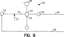
第9図は、第3A、3B図のような素子の流れ図である。
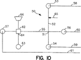
第10図は、第4図のような素子の流れ図である。
第11図は、第5図のような素子の流れ図である。
第12図は、第6図のような素子の流れ図である。
第13図は、第7図のような素子の流れ図である。
第14図は、分離チャネルへの複数の入口を示した本発明による素子の実施の形態の一部の流れ図である。
第15図は、主電気泳動フローパスと2次電気泳動フローパスとの交差点の他の構成を示した本発明による素子の実施の形態の流れ図である。
第16図は、濃縮チャネルから下流に直列に配置された複数の分析ゾーンを示した本発明による素子の実施の形態の流れ図である。
第17図は、濃縮チャネルから下流に並列に配置された複数の分析ゾーンを示した本発明による素子の実施の形態の流れ図である。
第18図は、濃縮チャネルから下流の複数の主電気泳動フローパスを示した本発明による素子の実施の形態の流れ図である。
第19図は、並列に配置された複数の濃縮チャネルを示した本発明による素子の実施の形態の流れ図である。
第20図は、第15図に示されたものと類似しており、試薬を直接リザーバから主電気泳動フローパスに運ぶための試薬フローパスを追加的に有する本発明による素子の実施の形態の流れ図である。
第21図は、第16図に示されたものと類似しており、試薬を直接リザーバから主電気泳動フローパスに運ぶための試薬フローパスを追加的に有する本発明による素子の実施の形態の流れ図である。
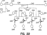
第22図は、第17図に示されたものと類似しており、試薬を直接リザーバから主電気泳動フローパスの下流路に運ぶための試薬フローパスを追加的に有する本発明による素子の実施の形態の流れ図である。
第23図は、濃縮媒質が被覆磁性ビードを含む本発明による素子の実施の形態の流れ図である。
詳細な説明
少なくとも濃縮チャネルと主電気泳動フローパスとを含む統合電気泳動マイクロ素子が提供される。濃縮チャネルは、液体試料の一部からなる特定の分析物を濃縮する役割を果たす。本素子においては、濃縮チャネルと主電気泳動フローパスは、濃縮チャネルからの廃流体が主電気泳動フローパスの中を流れず、排出口と通って主電気泳動フローパスから出るように配置されている。対象装置は、臨床検査分析を含む多種多様な電気泳動用途で使用することができる。以降の発明の説明においては、まず最初に素子について概説し、次に、図との関連で本発明の代表的な特定の実施の形態についての検討を行う。
本発明は統合電気泳動マイクロ素子である。統合とは、例えば、濃縮チャネル、主電気泳動フローパス等のような、素子のコンポーネントの全てが、チップ、ディスク等のような、単一で、コンパクトで、取扱いの簡単なユニットの中に存在していることを意味する。素子は電気泳動素子であるので、分子、粒子、細胞等のようなエンティティが適用された電界の影響の下で媒質の中を通過させられる多種多様な用途において有用である。例えば、電荷を有するかどうかのような、エンティティの性質に応じて、さらには、電気泳動が行われる電気泳動室の界面化学的性質に応じて、適用された電界の直接の影響の下で、又は、例えば、電気浸透流(EOF)のような、電界の適用により生じる流路の中のバルク流体流の結果として、エンティティを媒質の中を通過させることができる。マイクロ素子は、主電気泳動フローパスとしてのマイクロチャネルを含むことになる。マイクロチャネルとは、以下でさらに詳細に説明するように、媒質が入れられている主電気泳動フローパスの電気泳動室が、電気泳動室を貫流する毛管流を作り出す横断面積を有する、例えば、トレンチ又はチャネルのような、導管であり、電気泳動室が平面基板上に存在することを意味する。
対象素子にとって極めて重要であるのが、試料入口と、廃流体出口と、試料の特定の画分を濃縮するための内部濃縮媒質と、随意の濃縮画分流体出口とを含む濃縮チャネルである。濃縮チャネルの目的は、特定の画分を濃縮するために初期試料を処理することにあり、ここで、濃縮される特定の画分とは、関心を引く(目的の)単数又は複数の分析物である。従って、濃縮チャネルは、初期試料容積の残りの成分又は廃物部分からの画分を含む標的分析物を選択的に保持・分離する役割を果たす。素子が用いられる特定の用途に応じて、濃縮チャネルは多数の様々な機能を提供することができる。濃縮チャネルは関心を引く分析物を初期試料容積よりも小さな容積にする役割を果たすことができる、すなわち、分析物濃縮器としての役割を果たすことができる。さらに、濃縮チャネルは、潜在的な妨害試料成分が主電気泳動フローパスの中に入り、内部を貫流するのを防止する役割を果たすことができる、すなわち、試料「クリーンアップ」手段の役割を果たすことができる。それに加えて、濃縮チャネルは、例えば、ラベリング、蛋白質消化、DNA消化又は断片形成、DNA合成等の、化学的、免疫学的又は酵素学的手順のような、流体試料中に存在する標的分析物の調製手順用のマイクロ反応器の役割を果たすこともできる。
濃縮チャネルは、その内部に入れられた特定の濃縮媒質に応じて、多種多様な形状で素子の中に位置することができる。チャネルの内部容積は一般的に約1pl〜1μl、通常は約1pl〜100nlの範囲になり、チャネルの長さは一般的に約1μm〜1mm、通常は10μm〜1mmの範囲になり、横断面寸法(例えば、幅、高さ等)は約1μm〜200μm、通常は約10μm〜100μmの範囲になる。チャネルの横断面形状は、円形、楕円形、長方形、台形、正方形、又はその他の便利な形状とすることができる。
濃縮チャネル内では多種多様な濃縮媒質を使用することができる。代表的濃縮媒質又は手段としては、アメリカ特許第5,202,010号と、アメリカ特許第5,246,577号と、アメリカ特許第5,340,452号と、上記のTomlinson et al.に開示された分析物予濃縮素子に記載された手段とがあり、それらの開示内容は引用により本願に援用される。本発明のマイクロチャネル電気泳動素子内での使用に適用可能であると考えられる技術的に公知の特定の濃縮手段としては、Kasicka & Prusik,“Isotachophretic Electrodesorption of Proteins from an Affinity Adsorbent on a Microscale,”J.Chromatgr.(1983)273:117128に記載された蛋白質予濃縮素子に用いられたものと、アメリカ特許第5,202,010号とWO第93/05390号とに記載されたような親和性吸着剤を含む毛管束と、Cai & El Rassi,“On-Line Preconcentration of Triazine Herbicides with Tandem Octadecyl Capillaries-Capillary Zone Electrophoresis,”J.Liq.Chromatogr.(1992)15:1179-1192に記載されたようなオクタドデシルシラン被覆固体相と、Cai & El Rassi,“Selective On-Line Preconcentration of Proteins by Tandem Metal Chelate Capillaries-Capillary Zone Electrophoresis,”J.Liq.Chromatogr.(1993)16:2007-2024に記載されたような金属キレート層被覆固体相と、アメリカ特許第5,246,577号に記載されたような逆相HPCL固体パッキング材料と、Cole &Kennedy,“Selective Preconcentration for Capillary Zone Electrophoresis Using Protein G Immunoaffinity Capillary Chrmatography,”Electrophoresis(1995)16:549-556に記載されたような蛋白質G固体相と、アメリカ特許第5,423,966号に記載されたような溶解性アガロースゲルと、Guzman,“Biomedical Applications of On-Line Preconcentration-Capillary Electrophresis Using an Analyte Concentrator:Investigation of Design Options,”J.Liq.Chromatogr.(1995)18:3751-3568に記載されたような親和性吸着剤と、アメリカ特許第5,318,680号に記載されたような固体相反応器材料とがある。上記引例特許及びその他の刊行物の各々の開示内容を本願に援用する。
濃縮媒質として使用することができる濃縮媒質又は材料の1つのクラスが、クロマトグラフ媒質又は材料、特に収着相材料である。かかる材料としては、例えば、C8又はC18化合物被覆粒子のような、逆相材料と、イオン交換材料と、結合成分が不溶性基質に共有結合された親和性クロマトグラフ材料とがあり、親和性クロマトグラフ材料の場合、結合成分は、例えば、レシチン、酵素共同因子、蛋白質A等のように、グループ特定とすることもできるし、例えば、その抗体又結合断片、関心を引く特定の抗体用の抗原、オリゴヌクレオチド等のように、物質特定とすることもでき、結合成分が結合された不溶性基質は、多孔性ガラスのような粒子、ポリマービード、磁性ビード、ガラスストランド又はフィラメントの網目、複数の細いロッド又は毛管、チャネルの壁等とすることができる。濃縮手段として用いられたクロマトグラフ材料の性質に応じて、クロマトグラフ材料を濃縮チャネル内に保持するために保持手段を用いることが必要になるかもしれない。電気泳動室の流体出口又は入口を覆うために、ガラスフリット又はアガロースゲルのプラグを用いるのが便利であり、フリット又はプラグは、濃縮チャネルからの流体の流出は許容するが、粒子又はその他の不溶性基質の流出は許容しない。濃縮手段がクロマトグラフ材料である実施の形態においては、典型的には、試料が濃縮チャネルの中に入れられ、その中を貫流させられる。試料が濃縮チャネルの中を貫流する時には、分析物含有画分はクロマトグラフ材料により保持され、試料の残りの廃物部分は廃物出口からチャネルの外に出る。
濃縮手段がポリマービード床又は常磁性ビード又は粒子床である実施の形態においては、ビードは、多種多様なあらゆるほ乳類細胞マーカ、特に、T細胞、T細胞サブセット、B細胞、単球、幹細胞、骨髄細胞、白血球及びHLAクラスII正細胞用のマーカを含むヒト細胞マーカに対する親和性精製モノクロナール抗体と、B細胞、T細胞及びT細胞サブセットの分離用の多種多様なあらゆるげっ歯動物細胞マーカ、特にマウス、ラット又はウサギ免疫グロブリンに対する2次抗体と、何らかの生体分子をカスタム被覆するための未被覆又はトシラクト化形態抗体と、ビオチニレート化抗体とともに使用するためのストレプタビジン被覆抗体とを含む、抗体又はその他の標的特定親和性結合成分により被覆することができる。常磁性ビード又は粒子は磁界の適用により濃縮チャネル内に保持することができる。
代替的に、又は、濃縮手段としての被覆粒子又はその他の不溶性基質のような固体層材料に加えて、試料の分析物含有画分を選択的に保持しつつ、試料の残りを貫流させ、廃物出口から濃縮手段の外に出すことを可能にする被覆及び/又は含浸膜を使用することができる。本発明において使用することもできる固体層抽出の際に使用するために、多種多様な親水性、疎水性及びイオン交換膜がすでに開発されている。例えば、Tomlinson et al.,“Novel Modifications and Clinical Applications of Preconcentration-CapillaryElectrophoresis-Mass Spectrometry,”J.Cap.Elect.(1995)2:97-104と、Tomlinson et al.,“Improved On-Line Membrane Preconcentration-Capillary Electrophoresis(mPC-CE),”J.High Res.Chromatogr.(1995)18:381-3とを参照。
代替的に又は追加的に、濃縮チャネル又は濃縮媒質は多孔性膜又はフィルタを含むことができる。ゲノムDNAやウイルス核酸を捕獲するのに適した材料としては、QIAGEN社によりQIAmpの名前で販売されているものがあり、DNAを植物細胞や組織から捕獲するのに適した材料としては、QIAGEN社によりDNeasyの名前で販売されているものがある。
素子の形状に応じて、多種多様な手段のいずれか1つ又は複数の手段の併用により、試料に濃縮チャネルの中を貫流させることができる。いくつかの素子形状の場合、試料に働く重力により、試料に濃縮チャネルの中を貫流させることで十分であろう。いくつかの形状の場合、所望の方向に遠心力を働かせるために、素子を選択された軸のまわりでスピンさせることもできる。その他の実施の形態においては、試料に濃縮チャネルとその内部に収容された濃縮手段の中を通過させるために、能動ポンピング手段を用いることもできる。その他の実施の形態においては、試料を動かすために、又は、洗浄及び溶離段階中に常磁性ビード・標的複合体を捕獲又は不動化するために、磁力を適用することもできる。本発明のさらに別の実施の形態においては、流体に濃縮チャネルの中を通過させる電界を適用するために、電極を用いることもできる。次に、濃縮試料画分を材料から分離し、主電気泳動フローパスに運ぶために、溶離液が濃縮媒質の中を貫流させられる。一般的には、電界を与えるのは、溶離液に濃縮チャネルの中を貫流させるためである。
対象用途においては、電気泳動ゲル媒質も濃縮手段として用いることができる。ゲル媒質が提供するふるい分け能力にかなりの違いがあることは公知である。媒質の気孔寸法を変えることと、気孔率の異なる2つ以上のゲルを用いることと、及び(又は)気孔寸法勾配を提供し、濃縮チャネルと主電気泳動フローパスとの間に適切な関係を選択することにより、初期試料の関心を引く分析物の画分だけが確実に主電気泳動フローパスに入るようにすることができる。例えば、主電気泳動チャネルと交差する濃縮チャネルを含み、濃縮チャネルが、試料の流動方向において、気孔率の大きいスタッキングゲルと気孔率の小さい第2のゲルとを含み、ゲルとゲルとの境界が濃縮チャネルと主電気泳動フローパスとの間に生じる素子を得ることもできる。この実施の形態においては、試料がスタッキングゲルの中に入れられ、電界が濃縮チャネル内で両ゲルに適用された後に、試料成分はスタッキングゲルの中を通過し、濃縮チャネルと主電気泳動フローパスとの交差点のゲル界面において狭い帯域に濃縮する。濃縮試料画分の狭い帯域が主電気泳動フローパスの中に入り、そこを通過するように、次に、第2の電界を主電気泳動フローパスに適用することができる。代替的に、濃縮チャネルは気孔率勾配を有するゲルを含むこともできる。この実施の形態においては、関心を引く帯域が濃縮チャネルと主電気泳動フローパスとの交差点に達すると、関心を引く帯域は主電気泳動フローパスの中に入り、それに沿って動くことができる。
核酸の濃縮及び/又は精製に特に有用な濃縮媒質としては、配列順特定捕獲媒質と総括捕獲媒質とがある。包括捕獲媒質としては、例えば、核酸を非特定結合するとともに、試料中のほとんど全てのDNAを保持すると予想することができるイオン交換及びシリカ樹脂又は膜と、試料中のほとんど全てのシングルストランドDNAを結合すると予想することができる不動化シングルスとランドDNA結合蛋白質(SSB蛋白質)と、試料中のほとんど全てのmRNAを結合すると予想することができるポリdT変性ビードとがある。配列順特定捕獲媒質としては、例えば、試料中の相補性配列順を有する核酸を結合すると予想することができるオリグヌクレオチドプローブや、試料中の相補性配列順によりハイブリッド形成された固体相ビオチニレート化プローブを結合すると予想することができるストレプタビデンのような、多種多様なあらゆる捕獲分子を不動化するビード
、膜、又は表面がある。捕獲分子の不動化に適したビートとしては、化学的又は物理的架橋ゲルと、ポリマー又はシリカベース樹脂のような、多孔性又は非多孔性樹脂とがある。
蛋白質の捕獲に適した媒質としては、以下のものある。すなわち、蛋白質の捕獲に適した媒質としては、陰イオン(例えば、DEAE)及び陽イオン交換を含むイオン交換樹脂と、疎水性相互作用化合物(例えば、C4、C8及びC18化合物)と、サルフヒドリルと、固有活性表面(例えば、プラスチック、ニトロセルロース吸取紙)と、活性化プラスチック表面と、Cibacronブルー、Remazolオレンジ及びProcoinレッドのような芳香族染料とがある。炭水化物には、蛋白質、レシチン、不動化疎水性オクチル及びフェニルアルカン誘導体の一部が適している。酵素には、特定の酵素基質生成物遷移状態中間物の類似体が適している。キナーゼには、カルモジュリンが適している。受容体に適した捕獲媒質としては、受容体配位子親和性化合物がある。
上記のように、濃縮チャネルは少なくとも1つの入口と少なくとも1つの出口を有する。もちろん、入口が1つの場合、入口は工程の濃縮段階においては試料を濃縮チャネルの中に入れ、工程の溶離段階においては溶離媒質を入れる役割を果たさなければならない。出口が1つの場合、出口は濃縮媒質により保持された画分から取出された試料の部分を排出し、溶離段階においては濃縮画分を電気泳動マイクロチャネルに送る役割を果たさなければならない。濃縮チャネル内に収容された特定の濃縮手段の性質と、特定の素子形状とに応じて、濃縮チャネルは、例えば、試料入口と溶離緩衝剤の役割を果たす複数の流体入口を有することもできるし、又は、濃縮チャネルは、例えば、廃物出口と濃縮画分流体出口との役割を果たす複数の出口を有することもできる。濃縮チャネルが主電気泳動フローパスと直接流体連通している場合、すなわち、流体が濃縮チャネルから直ちに主電気泳動フローパスの中に流入するように、濃縮チャネルと主電気泳動フローパスとが結合されている場合、濃縮チャネルは、廃物出口に加えて、試料の濃縮画分が主電気泳動フローパスの中に流入する際に通る濃縮画分出口を有することになる。例えば、洗浄及び/又は溶離溶剤を濃縮チャネルの中に入れるのに便利であれば、かかる溶剤を流体リザーバから濃縮チャネルの中に導くために、1つ又は複数の追加流体入口を備えることもできる。濃縮チャネルを通るバルク流体流を制御し、例えば、廃試料が主電気泳動フローパス中に流入するのを防止するために、例えば、バルブ、膜等のような、流体制御手段等を各入口及び出口と組合せることもできる。例えば、試料、溶離緩衝剤、試薬、反応物、洗浄又はすすぎ溶液等のような、流体とエンティティに、濃縮チャネルの中を通過させたいのであれば、濃縮チャネル内に存在する材料と流体に電界を適用可能な電極を備えることもできる。
本発明の素子の次のコンポーネントは主電気泳動フローパスである。主電気泳動フローパスは、チューブ状、トレンチ状又はその他の便利な形状を含む多種多様な形状を有することができ、フローパスの横断面形状は、フローパスを内部に有する基板の平面表面上にマイクロチャネルを形成するように、円形、楕円形、正方形、長方形、三角形等のいずれでも構わない。マイクロチャネルは、マイクロチャネル内に毛管流体流を形成するだけの横断面積を有し、しかも、例えば、幅、高さ、直径のような、横断面寸法の少なくとも1つが約1μm、通常は約10μmであるが、約200μmを超えることはなく、通常は約100μmを超えることはない。統合素子の特定の性質に応じて、主電気泳動フローパスは平面基板の表面上において直線でも、曲がっていても、その他の便利な形状でもよい。
主電気泳動フローパスと、あらゆる追加的電気泳動フローパスは、フローパス内に存在する媒質に電界を適用する少なく1対の電極と組合されている。用いられる電極が1対の場合、典型的には、1対の各電極がフローパスの各端に存在することになる。便利であれば、引用により開示内容がここに取入れられたアメリカ特許第5,126,022号に記載されたように、複数の電極を電気泳動フローパスと組合せることもでき、この場合、複数の電極が電気泳動フローパスに沿ったエンティティの精密な動きを可能にする。対象素子に用いられる電極は、組合せられた電気泳動フローパス内に存在する媒質に適正な電界を付与可能でありさえずれば、便利なタイプのものをどれでも使用することができる。
対象素子にとって極めて重要であるのが、実質的に試料の濃縮画分だけが主電気泳動フローパスの中を貫流するように、濃縮チャネルと主電気泳動フローパスが素子の中に配置されていることである。その目的で、素子は、さらに、例えば、廃物部分のような、濃縮画分以外の試料の一部を主電気泳動フローパスから排出ための排出出口を有する。従って、濃縮チャネルが主電気泳動フローパスと直接流体連通している場合、濃縮チャネルの中を通る廃流体フローパスは主電気泳動フローパスと交差関係になる。間接流体連通状態になるように、濃縮チャネルと主電気泳動フローパスが第2の電気泳動フローパスにより接続された本発明のその他の実施の形態においては、濃縮チャネルの中を通る廃物フローパスは主電気泳動フローパスと交差関係になる必要は必ずしもない。廃物フローパスと主電気泳動フローパスは相互に平行にすることもできる。
対象素子は、濃縮画分を濃縮チャネルから主電気泳動フローパスに移送する手段も有する。特定の素子形状に応じて、濃縮画分移送手段は、濃縮画分出口、2次電気泳動フローパス、又はその他の適当な移送手段とすることができる。主電気泳動フローパスに加えて第2の電気泳動フローパスを有することにより、濃縮試料画分を濃縮チャネルから主電気泳動フローパスに運ぶための導管として、第2の電気泳動フローパスを使用することが可能になる。廃物出口がたった1つの流体出口である実施の形態においては、濃縮チャネルと主電気泳動フローパスを間接流体連通関係にするためには、2次電気泳動フローパスの存在は不可欠である。
主電気泳動フローパスと、濃縮試料移送手段としての2次電気泳動フローパスに加えて、本発明の素子はさらに1つ又は複数の追加的電気泳動フローパスを有することもでき、これらの追加的フローパスは毛管サイズであってもなくてもよく、多種多様な役割を果たすことができる。複数の電気泳動フローパスを有する素子の場合、複数の電気泳動フローパスが主電気泳動フローパスと流体連通した分枝形状のような、多種多様な形状が可能である。アメリカ特許第5,126,022号を参照。その開示内容は引用によりここに取入れられている。
素子の中に存在する主電気泳動フローパス及び/又は2次電気泳動フローパスは、一端又は両端に、すなわち、フローパスのいずれかの端に、随意で流体リザーバを有することができ、通常はその流体リザーバを有する。リサーバが備えられている場合、主電気泳動フローパスの中への緩衝剤、溶離溶剤、試薬、すすぎ及び洗浄溶液等の導入、電気泳動フローパスからの廃流体の受取り等のための手段のような、多種多様な役割を果たすことができる。
本発明の素子の中に存在することができるもう1つの随意のコンポーネントは、初期試料容積の廃物部分を濃縮チャネルから受取り、貯蔵するための廃流体リザーバであり、この場合、廃物リザーバは排出口と流体連通している。特定の素子形状に応じて、排出口は廃物出口と同じでも、違っていてもよく、廃物リザーバの中に通じるか、又は素子からの出口を提供する。廃物リザーバは、チャネル、コンパートメント、又は装置のその他のコンポーネントの障害とならないその他の便利な形状のものとして、素子の中に存在することができる。
本発明の素子は、やはり随意で、試料調製手段の中への試料の導入を助けるインタフェース手段を有することもできる。例えば、試料をシリンジにより素子の中に導入しなければならない場合、素子は、シール等のような、シリンジ針を素子の中に案内する役割を果たすシリンジインタフェースを有することもできる。
特定の形状と素子の材料の性質とに応じて、少なくとも主電気泳動フローパスとの関連で、電気泳動フローパス内に含まれた媒質中の特定の種の存在を検出するための検出領域が決まることになる。検出領域内の主電気泳動フローパスの少なくとも1つの領域は、光学的に透明で、一般的には180〜1500nmの、通常は220〜800nmの、より通常は250〜800nmの波長の光の透過損失を小さくすることを可能にする材料から製造される。適当な材料としては、融解シリカ、プラスチック、石英ガラス等がある。
統合素子は、濃縮チャネル及び主電気泳動フローパスと、任意の追加的コンポーネントを備えることが可能なでありさえすれば、便利な形状をどれでも有することができる。素子はマイクロチャネル電気泳動素子であるので、電気泳動フローパスは平面基板の表面上に存在しており、この場合、基板は通常は、必ずしも不可欠ではないが、表面上に存在するマイクロチャネルを環境からシールするために、平面カバープレートにより覆われている。一般的には、素子は小さく、表面平面における最大寸法がわずか約200mm、通常はわずか約100mmであり、その結果、素子の取扱いや操作が簡単になる。上記のように、素子は、例えば、クレジットカード又はチップ状、ディスク状、シリンジ状、又はあらゆるその他の便利な形状のような、平行パイプを含む多種多様な形状を有することができる。
本発明の素子は、ガラス、融解シリカ、アクリル、熱塑性プラスチック等を含む多種多様な材料から製造することができる。統合素子の種々のコンポーネントは、素子の特定の用途、経済的関心、溶剤相容性、光学的透明度、色、機械強度等に応じて、同じ材料から製造することも、異なる材料から製造することもできる。例えば、マイクロチャネル電気泳動フローパスを含む平面基板とカバープレートの両方を、例えば、ポリメチルメタクリレート(PMMA)のような、同じ材料から製造することも、例えば、基板はPMMAから、カバープレートはガラスからというように、異なる材料から製造することもできる。使捨て統合素子を有することが望ましい用途の場合、製造の容易さと材料のコストの点から、素子は典型的にはプラスチックから製造される。探知と製造の容易さのために、上に定義したような、光学的に透明なプラスチック材料から、素子全体を製造することもできる。特定の用途において興味深いのが、電気泳動の条件の下での表面電荷が低いプラスチックである。使用される特定のプラスチックとしては、ポリメチルメタクリレート、ポリカーボネート、ポリエチレンテレフタレート、ポリエチレン又はポリスチレンコーポリマー等がある。
素子は、従来の成形及び流込み技術を含む、いずれかの便利な手段により製造することができる。例えば、プラスチック材料から製造される素子の場合、素子の平面基板の中のチャネル構造用のネガであるシリカ成形マスタは、エッチング又はレーザミクロ機械加工により製造することができる。基板の中にチャネルを形成する浮彫りリッジを有することに加えて、シリカ成形マスタは、濃縮チャネルを収容するために平面基板の中に空洞を提供する浮彫り領域も有することができる。次に、ポリマー前駆物質製剤を、シリカマスタと、ガラス板のような支持平面板との間で、熱硬化又は光重合化することができる。便利であれば、その開示内容が引用によりここに取入れられたアメリカ特許第5,110,514号に記載された手順を用いることもできる。平面基板が製造された後に、濃縮チャネルを平面基板の空洞の中に配置し、所望する場合は、電極を入れることができる。最後に、カバープレートを基板の表面にかぶせて、シールし、それにより、統合素子を形成する。カバープレートは、超音波溶接、接着剤等を含む、いずれかの便利な手段を使用して、基板にシールすることができる。
一般的には、本発明の素子を使用する前に、適当な第1又は電気泳動媒質が、素子の電気泳動フローパス又はマイクロチャネルの中に入れられ、この場合、第1の媒質は、濃縮チャネル内に存在する濃縮媒質とは違ったものになる。電気泳動媒質という言葉は、媒質の中で種を動かすために電界が適用されるいずれかの媒質を表すために使用されている。電気泳動媒質は、基板へのカバープレートのシールの前に、電気泳動フローパスの端に存在するリザーバ経由で又は直接に電気泳動フローパスのチャネル又はチャンバの中に簡便に入れることができる。いずれかの便利な電気泳動媒質を用いることができる。使用に適した電気泳動媒質としては、Barron & Blanch,“DNA Separations by Slab Gel and Capillary Electrophoresis:Theory and Practice,”Separation and Purification Method(1995)24:1-118と、その開示内容が引用によりここに取入れられたアメリカ特許出願第08/241,048号、第08/636,599号、及び第08/589,150号とに記載されたような、緩衝剤、架橋及び非架橋ポリマー媒質、有機溶剤、清浄剤等がある。電気泳動媒質として特に興味深いのは、セルロース誘導体、ポリアクリルアミド、ポリビニルアルコール、ポリエチレン酸化物等である。
以下、本発明を図を参照してさらに説明する。第1図は、本発明による素子で使用することもできる濃縮チャネルの略図である。濃縮チャネル10は、逆相C18材料2を囲む側壁1を含む。チャネル10はさらに流体入口7及び4と、流体出口5及び6とを含む。チャネル入口及び出口を通る流体流を制御するために、バルブ8、9及び10が備えられている。ガラスフリット3は、流体流が入口4及び出口5を通るのを許容するが、しかし逆相材料2をチャネル内に保持する。この濃縮チャネルを使用する際には、試料がフローパス12の方向で試料入口7を通って中に入れられる。試料がチャネル10の中を通過するにつれて、画分を含む分析物は逆相材料2上に保持され、一方、試料の残りの廃物画分は廃物出口6からフローパス13に沿って外に出る。試料が入口4又は出口5から流出又は「漏出」するのを防止するために、バルブ8及び9は閉じられている。試料がチャネル10を通過した後に、バルブ11が閉じられ、バルブ8及び9が開かれる。次に、溶離緩衝剤がガラスフリット3及び試料入口4を通ってフローパス14の方向でチャネル10の中に入れられる。溶離緩衝剤が材料2の中を通過するにつれて、試料の保持された画分が分離され、溶離緩衝剤とともに濃縮画分出口5からフリット3を通ってフローパス15に沿って搬出される。
第2図には、逆相材料2に代わって、結合対部材が共有結合された架橋ガラスフィラメントの編み6が使用されている点を除いて、第1図に示したものと同じ濃縮チャネルが図示されている。
第3A図は、本発明によるクレジットカード形(長方体)素子の略平面図である。素子30は、第1端にリザーバ32を有し、第2端にリザーバ33を有する主電気泳動フローパス31を含む。主電気泳動フローパス31と直接流体連通しているのが、濃縮チャネル34(上から見て)である。電気泳動フローパス31内に存在する媒質に電界を適用するために、電極35及び36が備えられている。フローパス内に含まれた媒質中に存在する分析物を見るために、検出領域37が電気泳動フローパス31の上方に配置されている。検出領域は濃縮チャネル34の上方にも備えることができる。第3A図に示された素子は濃縮チャネルを1つしか含んでいないが、追加の濃縮チャネルを、検出領域内を含めて、フローパス内に備えることもできる。
第3B図は、第3A図に示された素子の略側面図である。本発明のこの実施の形態を使用する際には、試料はシリンジインタフェース38を通じて濃縮チャネル34の中に入れられ、サンプルの画分である分析物は保持されるが、廃物画分は排出口39を通って濃縮チャネル34の外に出て、素子の外に流出する。溶離緩衝剤が次にポート40からリザーバ32の中に入れられる。次に、溶離緩衝剤をリザーバ32から濃縮チャネル43を通って電気泳動フローパス31に沿ってリザーバ33まで移動させる電界が電極35と36との間に与えられる。溶離緩衝剤が濃縮チャネル34の中を通過するにつれて、溶離緩衝剤は初期試料容積の画分である保持された分析物を分離し、これを電気泳動フローパス31の中に運ぶ。
第4図は、濃縮チャネル62が2次電気泳動フローパス55により主電気泳動フローパス52から分離されている本発明の実施の形態の略図である。素子50の場合、試料はシリンジインタフェース66を通じて濃縮チャネル62の中に入れられる。試料が濃縮チャネル62の中を流れるにつれて、廃試料は排出口64を通って廃物リザーバ63の中に流入する。次に、電界を電極61と60との間に与えリザーバ57の中に存在する溶離緩衝剤を濃縮チャネル62を通って移動させ、その結果、分析物を分離する。分析物は次に溶離緩衝剤とともに2次電気泳動フローパスに沿って運ばれる。分析物が交差点51に達すると、電極59と58との間の電界が電極60と61との間の電界に代わる。本発明のこの実施の形態又は類似の実施の形態においては、分析物が交差点51に達する時期は、交差点における分析物の存在を検出することにより、又は、分析物の特定の性質、フローパス内の媒質、電界の強さ等に基づいて、分析物が交差点に達するはずの時期を経験的に定めることにより、定めることができる。リザーバ54と53とにそれぞれ配置された電極59と58との間の電界付与後には、分析物は交差点51から電気泳動フローパス52に沿ってリザーバ53に向かって移動し、検出領域65を通過する。
第5図は、濃縮チャネルが流体入口と出口を1つしか有していない本発明のさらにもう1つの実施の形態の略平面図である。素子70は、2次電気泳動フローパス73と交差関係にある主電気泳動フローパス71を含む。2次電気泳動フローパス73に沿った交差点82の上流に、濃縮チャネル72がある。この実施の形態を使用する際には、試料はシリンジインタフェース80を通じて濃縮チャネル72の中に入れられ、それにより、試料の画分である分析物は濃縮チャネル内に存在する材料に可逆結合される。次に、試料の不可逆結合した又は廃物画分を濃縮チャネル72の外に出し、2次電気泳動フローパス73に沿って移動させ、交差点82を通過させ、排出口84から廃物リザーバ78の中に入れる電界が、電極81と79との間に適用される。次に溶離緩衝剤がシリンジインタフェース80を通じて濃縮チャネル72の中に入れられ、溶離緩衝剤を濃縮チャネル72を通って2次流電気泳動フローパス73の中に流入させ、溶離緩衝剤とともに分析物を運ぶ電界が、電極81と79との間に与えられる。分析物が交差点82に達すると、電極76と77との間の電界が電極79と81との間の電界に代わり、分析物を主電気泳動フローパス71に沿って移動させ、検出領域99を通ってリザーバ74に向かわせる。
第6図に概略的に示された素子は、第1〜5図の素子のクロマトグラフ濃縮手段の代わりに電気泳動濃縮手段を有する濃縮チャネルを含む。素子90においては、試料はリザーバ96の中に入れられ、試料をリザーバ98に向かって移動させる電界が電極87と88との間に付与される。試料は、リザーバ98に向かって移動するにつれて、気孔寸法の比較的大きいスタッキング(積重ね)ゲル93の中に入り、気孔寸法の比較的小さい2次ゲル92に向かって移動する。界面94においては、試料成分は狭い帯域に圧縮される。この地点で、電極89と90との間の電界が電極87と88との間の電界に代わって、界面93における試料成分の狭い帯域を主電気泳動フローパスの中に移動させ、検出領域91を通過させ、リザーバ85に向かわせる。素子90においては、スタッキングゲル構造の代わりに、限界質量を下回る試料成分を選択的に通過させ、限界質量を超える成分を表面に保持することができる分子サイズ膜を界面93の領域に備えることもできる。第6図に示された素子のさらにもう1つの変更例として、93の領域内の関心を引く試料成分を保持し、それにより、93の領域内の成分濃度を必要な高さに維持するために、適正な電位を付与することができる電極を、界面93の位置に配置することもできる。例えば、関心を引く陰イオン分析物の場合、試料をリザーバ96の中に入れ、正電極である93とアースである87との間に電界を付与することにより、陰イオン分析物は93の領域に向かって移動し、そこで濃縮される。分析物が電極93の領域で濃縮された後に、陰イオン分析物をリザーバ85に向かって移動させる電界を89と90との間に付与することができる。
第7図は、第3〜6図のクレジットカード形の実施の形態とは対照的な、本素子のディスク形の実施の形態の略平面図である。素子100においては、試料は最初に濃縮チャネル102の中に入れられる。電界が電極108と109との間に付与され溶離緩衝剤103を濃縮チャネル102の中を通過させ、それにより、濃縮チャネル102内に保持された分析物が分離され、溶離緩衝剤とともに交差点114まで運ばれる。次に、110と111との間の電界が108と109との間の電界に代わり、分析物を交差点114から主電気泳動フローパスに沿って移動させ、検出領域113を通過させ、リザーバ107に向かわせる。
その他の実施の形態は、第8〜19図の流れ図を参照することにより理解でき、その中のいくつかは第1〜7図に示された実施の形態に対応している。例えば、第8図には、第1図又は第2図に示されたような濃縮チャネルの流れ図が、対応する識別番号ともに示されている。従って、第1及び2図との関連で記載されているように、試料はフローパス12を通って試料入口7から濃縮チャネル10の中に入る。試料が濃縮チャネル10の中を通過するにつれて、例えば、(第1図との関連で記載されたような)逆相C18材料のこともあるし、(第2図との関連で記載されたような)ガラスフィラメントの網に共有結合された結合対部材のこともある、関心を引く画分を含む画分は濃縮媒質上に保持され、一方、残りの廃物画分は廃物出口6からフローパス13に沿って流出される。適当な量の試料が濃縮チャネル10の中を通過し、入口7及び出口8を通る流れが停止され、溶離緩衝剤がフローパス15を通って入口4から濃縮チャネルの中に入る。濃縮チャネル10の内部では、関心を引く保持された画分が分離されて、溶離緩衝剤の中に入り、濃縮媒質を通過し、フローパス15を通って濃縮画分出口5から外に出る。
第9図には、第3A、3B図の2つの図に図示され、図との関連で記載されたような素子30の実施の形態の流れ図が示されている。流れ図においては、濃縮チャネル(第3A、3B、9図では34)は正方形により表され、種々のリザーバ(例えば、第3A、3B、9図では32、33)は、フローパス(チャネル)の端の小さな円により表され、フローパス(例えば、第3A、3B、9図では主電気泳動フローパス31)は線により表され、電極(第3A、3B、9図では35、36)は、リザーバを表す円の中心までのびた細線により表され、シリンジ注入用のインタフェース(1つが存在する場合あり;例えば、第3B、9図では38)は試料入力フローパスの端の台形により表されている。検出領域(第3A、3B、9図では37)は、主電気泳動チャネルに触れている太い矢印により表されている。同様に、第12図には、第6図に図示され、図との関連ですでに記載されたような素子90の実施の形態の流れ図が示されている。この実施の形態においては、濃縮チャネル(第12図では120)は電気泳動濃縮により動作し、その結果、濃縮チャネル120が主電気泳動チャネル95と交差する地点に、関心を引く画分が集まることになる。電極87、88の間の電位差を与えることにより、試料材料が濃縮チャネルの中を通過することができ、電極89、90の間の電位差を与えることにより、関心を引く画分を濃縮チャネルから溶離させ、主電気泳動チャネルを通過させ、検出帯域91に送ることができる。第6図に関して上に記載したように、統合点はスタッキングゲル93と2次ゲル92との間の界面94とすることができる。別の変更例においては、濃縮チャネルの界面の領域に必要な成分濃度を提供するために、適当な電位を界面93の位置の電極(第12図では121)に与えることができる。
第10図は、第4図に図示され、第4図との関連で上に記載されたような、濃縮チャネル62が2次電気泳動フローパス55により主電気泳動フローパス52から分離されている素子50の実施の形態の流れ図である。同様に、第13図は、第7図に図示され、第7図との関連で上に記載されたような、素子100のディスク形の実施の形態の流れ図である。第13図は、試料をシリンジインタフェース66から濃縮チャネル102の中に入れる際に使用される試料入力フローパスと、関心を引く画分を濃縮チャネル内の保持媒質上に保持しつつ、廃物を廃物リザーバに送る際に使用される排出口64とを示している。これらの特徴は第7図又は第4図の平面図には図示されていない。
第11図には、第5図に図示され、第5図との関連で上に記載されたような、濃縮チャネル72への流体入口と、濃縮チャネル72からの流体出口が1つしかない素子70の流れ図が示されている。シリンジインタフェースによる試料の注入中には、流体入口116は試料入口の役割を果たし、流体出口118は廃物出口の役割を果たす。関心を引く画分は保持媒質により濃縮チャネル内に保持されるが、一方、廃物画分は下流に流れて2次電気泳動フローパス73を通過し、2次電気泳動フローパスと主電気泳動フローパス71との交差点82を横断し、排出口84の中に入り、この排出口は廃物を主電気泳動フローパスから廃物リザーバ78に向かわせる。溶離中には、溶離緩衝剤はシリンジインタフェースにより注入される。流体入口116は溶離緩衝剤入口の役割を果たし、流体出口118は2次電気泳動チャネルへの濃縮画分出口の役割を果たす。関心を引く画分は溶離緩衝剤の中に入り、溶離緩衝剤中では、電極79、81を横断して2次電気泳動チャネルと主電気泳動チャネルとの交差点に電圧を与えることにより形成される電界の中で界面動電駆動される。関心を引く画分が交差点に達すると、関心を引く画分中の1つ又は複数の分析物を主電気泳動フローパスの中に引込み、主電気泳動フローパスに沿って検出ゾーン99に送るために、電圧が電極76、77を横断して付与される。
第5図との関連で指摘されたように、廃物画分(濃縮媒質に結合しなかった材料)は、濃縮チャネルの上流の電極と排出口の下流の電極との間に電界を与えることにより、濃縮チャネルと主電気泳動経路から洗流すことができる。すなわち、溶離緩衝剤を濃縮チャネルの中に入れる前に、液体洗浄媒質が濃縮媒質を通過させられ、排出口から外に出され、廃物画分成分を運去る。洗浄媒質が関心を引く画分を濃縮媒質から溶離しない限りは、どんな材料でも洗浄媒質としての適性を有する。さらに、濃縮媒質と結合したり、その他の形で一体化することがある好ましくない成分を溶離の前に選択的に分離又は除去する作業を楽にするように、洗浄媒質を選ぶこともできる。例えば、関心を引く成分がDNA断片である場合、洗浄媒質は、蛋白質又はポリペプチドを選択的に減成するか、又はRNAを選択的に減成し、溶離の前の関心を引く画分からのこれらの汚染物質の除去を楽にする酵素を含むことができる。又は、例えば、関心を引く成分が蛋白質である場合、洗浄媒質はDNAsesとRNAsesとを含むことができる。
濃縮チャネルの中に入り、濃縮チャネルの中を通過する各種の液体の連続的な動きは、濃縮シャネルの上流部に各液体用のリザーバとフローパスとを提供することにより、簡単に制御することができる。例えば、第14図の流れ図に図示されたように、濃縮チャネル210への入力部212は、試料リザーバ218からのびる試料供給フローパス220と、洗浄媒質リザーバ217からのびる洗剤媒質フローパス218と、溶離媒質リザーバ215からのびる溶離媒質フローパス216により供給を受ける。電位を(図示されてない)電極を横断して各リザーバと濃縮チャネル214の下流の(種々の形状についてここに記載されたような)適当な地点とに与えることにより、これらの材料の動きを選択的に制御することができる。蛋白質に適した洗浄媒質としては、例えば、pH調節緩衝剤と有機溶剤とがある。洗浄は、例えば、洗浄媒質のイオン強度又は温度を調節することにより行うことができる。
その他の材料も入力フローパスに入れることができ、特に、濃縮チャネル上に移動させる前の試料自体の前処理のために、1つ又は複数の試薬流を供給することができる。体液(例えば、血液、リンパ液、羊水、随液、又は尿)の未加工の試料は、試料フローパス内で試料を試薬と結合させることにより前処理することができる。例えば、酵素又は洗浄剤を含む試薬の混合により、DNAを全血の未加工試料中の細胞から分離することができる。
濃縮チャネルの下流のフローパスについては、その他の構成を用いることもでき、これらの構成のあるもの、関心を引く画分の成分の特定の種類の下流処理又は分析に関していくつかの効果を提供することもできる。例えば、第15図では、2次電気泳動フローパスは主電気泳動フローパスを横断していない。主電気泳動フローパス238はT字形交差点において2次電気泳動フローパス236とつながっている(第12図と比較せよ)。この構成においては、主電気泳動フローパスの上流部は2次電気泳動フローパス236と同じチャネル内をのびている。ここに記載されたその他の構成の場合と同様に、試料は試料リザーバ233から試料フローパス234を通って濃縮チャネル230の中に入る。濃縮段階中には、廃流体は2次電気泳動フローパス236を通って濃縮チャネル230から外に出て、次にT字形交差点237を通過し、排出口240から廃物リザーバ241に達する。濃縮段階が終了すると、洗浄媒質を濃縮チャネルの中に流し、同様に排出口から排出することができる。洗浄媒質は、試料供給フローパスを通じて中に入れることもできるし、又は、随意で、第14図との関連で上に記載されたような独立の洗浄媒質フローパスから中に入れることもできる。電界を(図示されていない)電極を横断して廃物リザーバ241と、試料リザーバ233と(随意で、洗浄リザーバと)に与えることにより、試料と洗浄媒質を動かすことができる。次に、溶離媒質を溶離緩衝剤リザーバ231から溶離緩衝剤経路235を通じて濃縮チャネル230の中に入れ、濃縮チャネル230の中を通過させ、2次電気泳動経路236の中を通過させることができる。関心を引く大部分の下流成分が交差点237に達するまで、溶離画分成分の下流の媒質を主電気泳動フローパス238から遠ざけ、廃物排出フローパス240を通じて排出することができる。次に、成分を2次電気泳動フローパス236から取出し、交差点237を通って主電気泳動フローパス238の中に入れ、検出領域242に向かわせ、そこを通過させるために、電位をリザーバ239に与えることができる。
例えば第5、12図に示されたように、「注入クロス」において主電気泳動フローパスと2次電気泳動フローパスとが交差していることが、例えば、主電気泳動フローパスが電気泳動分離に使用される場合のように、試料プラグの精密な計測が望ましい場合に有利である。かかる注入クロスは、関心を引く画分からの試料成分の幾何学的に形成されたプラグを交差点から注入することを可能にする。
一方、試料プラグの精密な制御が望ましくなく、特に、全ての溶離試料が主電気泳動経路の中を通過することが望ましい場合、T字形交差点の方が好ましい。かかる構成は、例えば、ほぼ全ての全ての溶離試料に交差点の下流の一連の親和性ゾーンを通過させることにより成分の分析を行う場合に有利である。
例として、第16図には、直列配列の親和性ゾーン244、246、248、250を有する構成の中での流れを示した図が示されている。各親和性ゾーンは、関心を引く画分の選択された成分に対する特定の親和性を有する濃縮媒質を備えている。例えば、関心を引く画分が粗細胞溶解物中のDNAからなることがあり、しかも、溶解物は濃縮チャネル230の上流で形成され、濃縮チャネル230内で濃縮及び/又は精製されたものかもしれず、その結果、主電気泳動フローパス238の中に入る溶離画分は主として長さ及び基本組成が異なるDNA断片の複雑な混合物からなる。各ハイブリッド形成ゾーンはそれ自体が濃縮チャネルであり、その内部の濃縮媒質は、標的DNA配列順に対して相補性の配列順を有する不動化オリゴヌクレオチドプローブを含む。溶離画分が親和性ゾーン244、246、248、250の中を逐次通過するにつれて、親和性ゾーンの1つの中のプローブに対して相補性の画分中に存在するあらゆる標的DNAがその親和性ゾーンの中で結合される。親和性ゾーンには、親和性ゾーン内で結合された関心を引く成分からの(蛍光又は電気化学ルミネセンスのような)信号を検出し、随意で、定量化するように形成された検出器243、245、247、249を備えている。当業者には理解されるであろうが、あらゆる形態の生体分子認識を親和性ゾーン内での捕獲原理として用いることができる。有用なタイプと親和性としては、抗体・抗原相互作用と、ポリdTとアデニル酸塩RNAとの結合と、RAN、DNA、PAN用のオリゴヌクレオチドプローブと、ストレプタビジン・ビオチン結合と、DNA結合蛋白質G又は蛋白質Aのような蛋白質・DNA相互作用と、アルギニン、ベンザミジン、ヘパリン及びレクチンのような、グループ特定親和性を有する分子とがある。その他の例は当業者には明白であろう。
従って、例えば、捕獲原理は、受容体・配位子結合、抗体・抗原結合等を含むこともでき、その結果、本発明による方法及び素子は、免疫学的検定、受容体結合検定等の実施に、さらには、核酸ハイブリッド形検定の実施に役立てることができる。
代替的に、上記のように、2次電気泳動フローパスとの交差点の下流において、主電気泳動フローパスを分岐させ、第17図に例が示されているように、主電気泳動フローパスを平行配列することができる。図示された電気泳動フローパス238は2つの二叉にされており、その結果、4つの主電気泳動フローパス分岐路が下流に各廃物リザーバ262、264、266、268までのびている。分岐路は、この例では、親和性ゾーン254、256、258、260と、検出器243、245、247、249とを備えている。第22図との関連で以下により詳細に示されているように、(例えば、温度、pH、緩衝剤条件等のような)環境の適用特性は、各フローパス分岐路内で、その他の分岐路から独立して効果的に制御することができる。
第17図の例のように、親和性ゾーンが並列に配置されている場合、各親和性ゾーンは、主電気泳動チャネルに運ばれる全試料のアリコートを受取る。この実施の形態においては、親和性媒質の2つ以上により捕獲することができる試料成分は、各2つ以上の親和性ゾーンの中に現れることになる。例えば、プローブ配列順2つに対して相補性の2つの配列順の一方又は両方を含む核酸断片は、並列配置においては、これらの2つのプローブを含む2つの親和性ゾーンの中で捕獲される。一方、第16図の例のように、親和性ゾーンが直列に配置されている場合、各下流親和性ゾーンに達するのは、上流の親和性ゾーンにより捕獲されなかった試料成分だけである。この場合、例えば、親和性ゾーンの2つの中のプローブ配列順に対して相補性の2つの配列順の両方を含む核酸断片は、2つの親和性ゾーンのより上流のものの中でしか捕獲されない。1つの成分又は配列順を含むが、もう1つの成分又は配列順を含まない試料成分を識別することが望ましい場合、この配置が効果的であるかもしれない。
そして代替的に、上記のように、濃縮溶離試料の処理のために、複数の主電気泳動フローパスを備えることもできる。第18図の例により示したように、主電気泳動フローパス270は溶離試料を2次電気泳動フローパス236から一連の交差点272を通って運ぶことができる。各主電気泳動フローパス270は上流リザーバ(274)と下流リザーバ276を備え、それぞれ検出器278を備えている。この構成は、単一の濃縮試料画分のアリコートについて一連の試験又は検定又は測定を行うために用いることができ、上記のように、分析物の量の精密な測定を所望する場合、特に有用であろう。主電気泳動フローパス270の各々には、第16、17図との関連で上に記載されたように、1つの親和性ゾーンを備えることも、(第18図には図示されていない)一連の親和性ゾーンを備えることもできる。
又は、第19図の例により示されたように、複数の濃縮チャネル280が分岐試料供給マニホルドから281から試料を受取ることができる。各濃縮チャネル280は、溶離段階中に、主電気泳動フローパス284との交差点288に濃縮画分を運ぶことができる。濃縮段階中に(及び、随意で、洗浄段階中に)、廃物画分が交差点288から分岐試料排出マニホルドから283を通り、排出口240から廃物リザーバ241に搬出される。例えば、関心を引く画分がDNAの混合物である場合、さらには、DNAの配列順情報とサイズ情報の両方を得ることを所望する場合、かかる配置を特に効果的に使用することができる。第19図の配置は、例えば、サーザンブロット分析に類似した貫流分析に使用することができる。従来のサーザンブロット分析では、DNA断片は最初にゲル上で分離され、次に、プローブを相補性断片に結合することが可能な膜に運ばれる。サーザンブロット分析は主として手動ベンチトップ手順として行われ、非常に労働集約的であり、完了までに数日を必要とする。本発明による貫流分析は実質的に自動化されており、はるかに迅速に分析を完了することができる。
貫流分析においては、濃縮チャネルの1を除いた各々に、配置順特定不動化オリゴヌクレオチドプローブのような、配置順特定捕獲プローブが備えられ、濃縮チャネルの最後の1つには、試料中の全てのDNA断片を結合する総括捕獲媒質が備えられる。これらの異なる濃縮画分は溶離段階中に交差点288に運ばれ、次に、それぞれ検出器286を備えた主電気泳動フローパスの中を電気泳動により動かされる。総括捕獲媒質を入れた濃縮チャネルからの濃縮画分は、試料からの全てのサイズのDNAの混合物を含み、ある範囲の電気泳動移動度を有し、検出器を逐次的に通過し、結果として一連の信号ピークを形成する。その他の各濃縮チャネルからの濃縮画分は、各濃縮チャネル内の特定の捕獲媒質に対して相補性のDNAだけしか含んでいない。
いくつかの実施の形態においては、1つ又は複数の試薬を2次フローパスと主電気泳動フローパスとの交差点の下流の濃縮画分と結合することが望ましいことがある。第20図は、第15図に示されたものと類似した流れ図である。第20図では、試薬フローパス300が試薬(又は複数の試薬)をリザーバ301から主電気泳動フローパス238に運び、そこで、試薬は濃縮画分中の1つ又は複数の分析物と結合し、反応することができる。さらに、主電気泳動フローパスが2次電気泳動フローパスとの交差点の下流で分岐し、分岐路内に部分画分を形成する場合、各かかる下流分岐路には、試薬をリザーバから運ぶ試薬フローパスを備えることができる。かかる構成は、単一の試薬による部分画分の反復処理、又は異なる試薬による各部分画分の処理、又は2つ以上の試薬による部分画分の同時処理に対応することができ、いずれの場合も、濃縮部分画分中の分析物の相互作用により、特定の所望の結果が得られる。
第21及び22図は、第16及び17図に示されたものと類似した流れ図であり、複数の分岐主電気泳動フローパスを有し、各分岐路は親和性ゾーンを備えている。第21図では、試薬フローパス300が試薬(又は複数の試薬)をリザーバ301から主電気泳動フローパス238に運び、そこで、試薬は濃縮画分中の1つ又は複数の分析物と結合し、反応することができる。この実施の形態においては、試薬フローパス300が第1の二叉の上流の地点で主電気泳動フローパス238と交差しているので、リザーバ301により供給される試薬は、下流分岐路で処理され、各親和性ゾーン内で検出される全ての部分画分の反復処理を行う。第22図では、主電気泳動フローパス238の下流分岐路の各々には、独立の試薬リザーバ(303、305、307、309)からそれぞれ試薬を運ぶ試薬フローパス(302、304、306、307)が備えられている。かかる構成は、例えば、平行なハイブリッド形成ゾーンの独立ストリンジェンシー制御の提供のように、部分画分の異なる処理に対応することができる。
例えば、第18〜22図のいずれかに示されたようなフローパス又はそれらの組合せを提供する素子は、DNAプロファイリングに使用することができる。詳細には、例えば、制限断片多形性(“RFLP”)分析を、第22図に示されたようなリザーバ303、305、307、309内の複数の異なる単一座RFLPプローブを用いることにより行うことができる。多数のプローブを並列で行うことにより、結果としての対立因子の分布は、迅速かつ代表的DNAプロフィールをもたらすとともに、ランダムマッチの可能性を実質的に最小限に抑えるはずである。
対象素子は、媒質の中でエンティティを動かすために1つ又は複数の電界を媒質に対して適用する多種多様は用途において使用することができる。代表的な用途としては、電気泳動分離用途、核酸ハイブリッド形成、配位子結合、調剤用途、配列決定用途、合成用途、医療、環境、品質管理関連を含む分析物識別用途等がある。従って、特定の用途に応じて、多種多様な流体試料が対象素子の中に入れられることがあり、代表的な試料としては、体液と、例えば水等のような環境流体と、特定の分析物の識別及び/又は分離が所望されるその他の流体試料とがある。特定の用途に応じて、薬品、毒物、ペプチドや核酸のような自然生成化合物、蛋白質、糖蛋白質、有機及び無機イオン、ステロイド等を含む多種多様な分析物が関心を引くことがある。特に関心を引くのが、医療用途における対象素子の使用であり、その際、分析されることがある試料としては、血液、尿、血漿、随液、涙、鼻又は耳分泌物、組織溶解物、唾液、眼球スクラッチ、細針生検材料等があり、しかも、素子の中に入れる前に、試料の再処理が必要なことも、必要でないこともある、すなわち、粘度を低下させる、イオン強度を低下させる、特定のpHに対する溶性又は緩衝性を高める等のために、溶剤と併用する必要があることも、ないこともある。医療用途の場合、関心を引く分析物としては、陰イオン、陽イオン、薬品又は生体異物の代謝産物を含む小さな有機分子、ペプチド、蛋白質、糖蛋白質、オリゴ糖類、オリゴヌクレオチド、DNA、RNA、脂質、ステロイド、コレステロール等がある。
以下の例は説明のためのものであり、限定のためのものではない。
例
例1
水性試料中の有機分析物の高効率分離
第4図に示されたようなカードが、水性試料中の有機分析物の分離において、以下のように、カードの各リザーバの中への電極の挿入により適正な電界の適用を行い、検出領域65を通過する時に分析物を検出する手段を提供する素子と組合せて使用される。カード50の中では、濃縮チャネル62はC−18相により被覆された多孔性ビートを含み、リザーバ及びチャネルは、廃物リザーバを除いて、20ミリモルのホウ酸塩緩衝剤を含む。10μlの水性試料がインタフェース66を通じて濃縮チャネル62の中に注入される。試料中の有機分析物の実質的に全てがC18被覆多孔性ビードと可逆性結合し、一方、残りの試料成分は濃縮チャネル62から廃物リザーバ63の中に流入する。10μlの溶離緩衝剤(90%メタノール/10%20ミリモルホウ酸塩緩衝剤 pH8.3)が次にインタフェース66を通じて濃縮チャネル62の中に注入され、これにより、可逆性結合有機分析物が溶離緩衝剤中で遊離する。使用される溶離緩衝剤が少量であるために、元の試料中の分析物濃度と比較した溶離緩衝剤中の分析物の濃度は100〜1000倍になっている。リザーバ57および56の上のシールが次に除去され、電界が電極61と60の間に適用され、57中に存在する緩衝剤を56に向かって動かし、しかも、緩衝剤前面の動きが、濃縮された分析物を含む溶離プラグを交差点51に動かす。電圧勾配が次に電極58と59の間に適用され、溶離緩衝剤の容積中に存在する分析物の狭い帯域が分離チャネル52の中を通過するようにし、有機分析物の高効率分離を実現する。
上記の実験は第4図に示された素子の変更形態においても行われる。変更された素子においては、リザーバ57に加えて、素子はやはり濃縮チャネル62と流体連通している溶離緩衝剤リザーバを含む。この実験では、試料は濃縮チャネル62の中に入れられ、これにより、溶離緩衝剤中に存在する有機分析物は、濃縮チャネル内に存在するC18相被覆ビードと可逆性結合する。溶離緩衝剤リザーバ内に存在する電極と、電極60との間に、10μlの溶離緩衝剤が濃縮チャネルの中を通過し、あらゆる可逆性結合分析物を分離するのに十分なだけの制限された時間にわたり、電界が与えられる。溶離緩衝剤が濃縮チャネルの中に入った後に、電圧勾配が電極61と60の間に与えられ、上記のように、その結果として、緩衝剤が57から56に動き、定められた容積の有機分析物含有溶離緩衝剤が交差点51に運ばれる。
例2
統合マイクロフルイディック素子の内部での濃縮のために常磁性ビードを用いる試料濃縮
生体磁気分離法に基づく実験手順が本発明の実施の形態として提供される。一般的に第23図に示され、それとの関連で記載されたように構成されたマイクロフルイディック素子においては、特定の親和性媒質に対する結合親和性を有する標的を捕獲するために、特定の標的からなる試料が、親和性媒質を被覆された磁性ビードを使用して処理される。かかる磁性ビードは、例えば、ニューヨークのDynal社により、Dynabeads▲R▼の名前で販売されている。Dynabeadsは、細胞、遺伝子、バクテリア又はその他の生体分であることも、それらを含むこともある標的に選択的に結合する抗体又はその他の結合成分を被覆された超常磁性、単分散ポリスチレン微小球である。標的・Dynabead複合体は次に磁石を使用して分離される。結果として得られる生体磁性分離手順は簡単で、迅速で、信頼性があり、これにより、Dynabeadsは、複雑な不均質生体混合物から特定の標的を分離するための総括的濃縮媒質としての役割を果たすことになる。かかる磁性濃縮媒質は、本発明によれば、例えば、細胞生物学、分子生物学、HLA組織型別及び微生物学を含む、多種多様な用途に用いることができる。ここには、2つの実例が、特に、DNA生成と細胞分離の方法が提供される。
まず最初に、マイクロチャネルベース素子の一般的な説明が行われ、次に、生体磁性分離にDynal社製ビードを使用する方法の一般的な説明が行われる。
第22図の実例により示されたような統合マイクロフルイディック素子は、濃縮チャネルに結合された主電気泳動フローパス394を含み、濃縮チャネルは固体相抽出(SPE)室を含み、下流廃物リザーバ391に接続されている。濃縮試料検出領域393と液体出口リザーバ395とからなる主電気泳動フローパスはT字形交差点388において2次電気泳動フローパスとつながっている。この構成においては、洗浄用入口リザーバ373及び溶離緩衝剤溶入口リザーバ375と出口リザーバ391及び395との内部に配置された適切な電極を横断する電位を制御することにより、試料の界面動電操作が可能になる。
Dynabeadsが、次に、関心を引く試料が、それぞれ注入口ポート397及び377を通じて、素子の中に入れられる。濃縮室の内部においては、特定の標的に固有の試料とDynabeadsとの不均質懸濁液が低温放置され、ビードの表面上の特定の捕獲成分への固有吸着により、Dynabeadsが標的と結合することを可能にする。濃縮室380の側面に対する標的・ビード複合体の不動化は磁力により行うことができる。これは、希土類永久磁石を濃縮室に隣接配置することにより、手動で行うことができる。本発明のもう1つの実施の形態においては、SPE室に作用する適用磁界を制御するために、電磁手段を用いる自動化手順が使用される。
磁気不動化段階が完了すると、洗浄緩衝剤リザーバ373の中に入れられた洗浄媒質を経路374を通って濃縮チャネル380の中に移動させ、その中を通過させることができる。試料すすぎ中に、廃流体は濃縮チャネル380から出て、電気泳動フローパス384を通り、次にT字形交差点388を通過し、排出口392から廃物リザーバ391に達する。従って、洗浄段階からの上澄みは、廃物が主電気泳動ローパスの中を通過する必要なしで、システムから除去される。本発明のこの実施の形態は、検出領域393をまず最初に汚染することなしで、粗試料から標的生体分子を分離及び濃縮する効果的な手段を提供する。
例3
全血からのDNA精製
第22図に略図が示されたような電気泳動マイクロ素子を用い、全血からゲノムDNAを抽出し、精製するための濃縮媒質としてDynal▲R▼生体磁性ビードを使用する実験手順が提供される。血液源は、小さな乾燥法廷試料(例えば、1ナノグラム程度)でも、採取されたばかりの動脈血(わずか10μl)でも、骨髄(約5μl)でもよい。迅速なDNA分離及び溶離を可能にする実験手順が、増幅及び分析用の又は増幅なしの直接分析用のDNAのアリコートが得られるように、第23図の素子の内部で全血を処理するための自動化手順を実証する目的で提供される。作業は以下の段階を含む。
1.試薬及び試料充填
2.細胞溶解/DNA捕獲
3.反復性DNA洗浄
4.DNA溶離
以下、これらの段階の各々について、さらに詳細に検討が行われる。
市販のパッケージ入り試薬が使用されるこの実施の形態の場合、生体磁性分離媒質、溶解溶液及び試料の充填は、試薬及び試料の違いに対応する特別設計の注入ポートから行うことができる。最初に、溶解溶液と磁性ビードとを含むDynal社製DIRECTTM試薬が手動注入ポート379を通じて固体相抽出室380の中に直接注入され、それに続いて、全血試料が注入ポート377を通じてSPE室の中に注入される。代替的に、細胞核とビードとがキットとして一緒にパッケージされておらず、別々に供給されるその他の市販の試薬を使用することもできる。この場合、溶解溶液は入口リザーバ371からSPE室の中に界面動電により充填することができる。次に、例えば日本合成ゴム社により供給される磁性ビードが、注入ポート379から充填されるか、又は入口リザーバ369から界面動電により充填される。後者のアプローチの場合、ビードは、電磁捕獲、又はフローパス384内のSPE室のすぐ下流に配置された機械的手段(例えば、膜、メッシュスクリーン又はアガロースゲルプラグ)、又はその両方により、SPE室に閉込められる。SPE室にビードと溶解溶液とが充填されると、DNA試料が、注入ポート377を通じて添加されるか、又は、SPE室の下流の電極と対になった電極を備えた入口リザーバを通じて界面動電により添加される。
濃縮室の内部で、計液試料と溶解溶液とDynabeadsとは、細胞が溶解される5分間の間常温放置される。次に、分離された核酸が、微小粒子の表面上で不動化された捕獲成分に吸収され、DNA・ビード複合体を形成することができる。細胞溶解能力を高めるために、例えば、ビードと試料と溶解溶液との流れが合流するように、供給チャネルを配置することにより、混合を行うことができる。適用される電界をうまく制御することにより、混合度を界面動電により高めることができる。入口リザーバ371と出口リザーバ391との中に配置された電極の極性を周期的に逆転させることにより、血液・溶解緩衝材混合物をSPE室の内部で界面動電により振動させつつ動かすことが可能である。細胞に適用される機械的せん断力をさらに高めるために、アパーチャ状構造をSPE室ハウジングの中に形成することができる。
SPE室の側面におけるDNA・ビード複合体の磁力分離と捕獲とに続いて、リザーバ373内に入れられた洗浄緩衝材をSPE室を通って廃物リザーバ391まで界面動電運搬することにより、すすぎを行うことができる。この45秒間のすすぎの後に、ビードは磁界の適用により溶液中に再懸濁させられ、次に洗浄緩衝材中で1分間常温放置される。同じ手順の後に、すすぎがさらに2回繰返され、PCR阻害剤を含む廃物に主電気泳動フローパス394の中を通過させずに、各洗浄段階からの細胞Iysateと上澄みとをシステムから除去することを可能にする。
精製過程の最終段階はDNA溶離である。再度、溶離緩衝剤が界面動電によりリザーバ373からSPE室の中に運ばれる前に、捕獲ビードが結合DNAとともに電磁的に不動化される。量的溶離を確保するために、緩衝剤がSPE室の中を通過し、その結果、精製されたDNAを適時よりも早期に洗流してしまうことがないように、電位の精密な操作が必要である。代替的に、1997年6月18日提出のD. Benegnu et al.アメリカ特許出願第_/_,_,号(弁理士摘要書第A−64739/RFT/BK号)に記載されたような(第23図には図示されていない)注入クロスを用いることにより、溶離緩衝剤のプラグをSPE室の中に移動させることもできる。溶離緩衝剤がSPE室内にある状態で、ビードは磁界の適用により再懸濁させられ、次に溶離緩衝剤中に2分間常温放置され、有限DNA脱着運動を可能にする。DNA溶離が完了すると、ビードはSP室内で電磁的に不動化され、精製されたDNAは分析のために界面動電によりプラグとして主電気泳動チャネル394の中に注入される。検出領域395は、特に、制限酵素消化、サーザン及びスロット/ドットブロットを含むブロットハイブリッド形成、電気泳動断片サイジング、及び量的PCR分析用の複数のマイクロチャネルからなることもできる(第23図には図示されていない)精巧なマイクロ流体システムの代わりをすることができる。しかしながら、本発明のこれらの実施の形態については、この例ではこれ以上触れない。
要約すれば、上記の実験手順は、精製されたDNAのPCR対応アリコートを10分未満で分離することを可能にし、しかも、いったん粗試料がマイクロ純流体素子の中に入れられた後には、ユーザーが介入する必要はない。この方法のその他の効果としては、比較的労働集約的な沈殿又は遠心分離段階が不要であることに加えて、実験において消費される試薬が微量なことがある。等々。
例4
免疫磁気分離を用いる細胞濃縮
Dynal▲R▼生体磁気ビードが細胞標的を分離するための濃縮媒質として使用される実験手順が提供される。手順は、上記のDNA精製のための手順と類似している。例3と同様に、標的は、常磁性微小粒子の表面上で不動化された特定の結合成分を被覆されたビードにより捕獲される。Dynabeadsは、以下のように、様々な形態に形成されたものが入手可能である。
1.T細胞、T細胞サブセット、B細胞、単球、幹細胞、骨髄細胞、白血球及びHLAクラスII正細胞を含む多くのヒト細胞マーカに対する親和性精製モノクロナール抗体を予被覆されたもの。
2.げっ歯動物B細胞、T細胞及びT細胞サブセットの分離用のマウス、ラット又はウサギ免疫グロブリンに対する2次抗体を被覆されたもの。
3.何らかの生体分子をカスタム被覆するための未被覆又はトシラクト化形態のもの。
4.ビオチニレート化抗体とともに使用するためのストレプタビジン被覆形態のもの。
一般的に第23図に図示されたように構成されたマイクロ純流体素子においては、さらなる加工及び分析用の細胞の精製アリコートを調製するために、細胞の不均質懸濁液が界面動電及び磁気操作法を用いて処理される。SPE室に適用される磁界の電磁制御を用いることにより、生体磁気分離が手動又は自動化形式で可能である。以下の4段階手順が本発明の代表的な実施の形態として提供される。
1.生体磁気分離媒質を含む標的細胞及び試薬の充填
注入ポート379を通じて直接に、又は、特定の標的に固有のDynalビードの溶液の入った入口リザーバ371から界面動電により、SPE室380の中に磁性ビードの溶液を充填する、あるいは又、Dynabeadsの溶液を満たされたSPE室に試料注入ポート377から直接に試料を添加する。
2.特定の標的を結合することが可能なDynabeadsを用いる細胞捕獲
試料及びビードを2.5分間SPE室の内部に常温放置し、界面動電混合段階を用いて吸着性を高め、標的細胞をDynabeadsに結合させ、標的・ビード複合体を形成する。
3.ビード・標的細胞複合体の不動化による標的細胞洗浄
結合標的を含む捕獲ビードを電磁的に不動化し、界面動電操作により洗浄緩衝剤溶液をですすぎを行う。
洗浄緩衝剤が入口リザーバ373からSP室を通って廃物出口391に達するように電極電位を制御することにより、上澄みを除去する。
流れを45秒後に止め、磁界を適用することにより標的・ビード複合体を溶液の中に再懸濁させる。
標的・ビード複合体を洗浄緩衝剤中に1分間常温放置する。
上記の洗浄段階をさらに2回繰返す。
4.Dynal社製DETACHaBEADTM試薬を用いる標的細胞溶離
捕獲ビードを電磁的に不動化し、DETACHaBEADTM試薬をSP室の中に充填する。
溶離緩衝剤がSP室の中を通過しないですむようにするために、電極電位の操作により、界面動電でDynal抗体ベース試薬を溶離緩衝剤リザーバから移動させるか、又は、代替的に、(第22図には図示されていない)注入クロスを使用し、溶離緩衝剤のプラグをSP室の中に注入することができる。
磁界の適用によりビードを再懸濁させる。
有限脱着運動を可能にするために、ビード複合体を洗浄緩衝剤中に2分間常温放置する。
標的溶離が完了すると、ビードを電磁的に不動化する。
さらなる処理及び分析のために、分離された標的細胞を界面動電によりSPE室から主電気泳動チャネルの中に運ぶことができる。
マイクロ純流体素子及びマイクロ純流体法を用いる細胞分離は、従来のフローサイトメトリー技術に代わる費用対効果の大きい技術を提供する。それに加えて、生体磁気分離技術と併用された場合、マイクロ流体式アプローチは、感度の向上及び暗騒音の減少をもたらす細胞濃縮及び検出を可能にする。マイクロ純流体ベース磁気分離法は標的物質に最小限のストレスしか与えず、従って、細胞を無傷かつ生存可能な状態に保ち、ポリメラーゼ鎖反応増幅と組合された逆転写(RT−PCR)における直接使用が可能である。マイクロ純流体ベース法は、フェノール抽出、エタノール沈殿、又は遠心分離を用いず、有毒試薬をほとんど用いることがない。分離は高価な装置の使用なしで行われ、高く評価される。
例5
費用対効果の大きい疾病管理のための手段
遺伝子治療が研究室段階から臨床段階に移行するにつれて、治療学と診断学の結付きがより緊密になってくる。その結果、臨床における生物機器を使用したDNAベース薬剤の効力のモニタリングが、これらの治療の成功を保証するために非常に重要になる。詳細には、細胞採集及び分離過程と新たに登場してきた分子的DNA増幅及び検出法とを統合するためのマイクロ純流体ベース素子は、この市場ニーズに応じられる見込みが非常に高い。従って、この用途において上記のような方法(特に、例3と4)を併用することにより、1つの分析機器が、費用対効果の大きい疾病診断能力と、医師が特定の遺伝子治療の適合性を評価するのを助けるモニタリングの能力とを有することが可能である。ゲノム後時代が急速に近づくにつれて、かかる効果的な疾病管理戦略は、その他の薬理遺伝学的アプローチに加えて、幅広く普及する潜在的可能性を有する。
本発明のこの実施の形態を説明する目的で、血液起因疾病を管理するためのシステムが提示される。
背景としては、遺伝血液障害が、ヒトがかかる最も多い遺伝疾患だということがある。世界保健機構は、世界の人口の約5%が様々なタイプのヘモグロビン障害のキャリアであり、約300,000の新しい症例が毎年診断されると推定している。鎌状赤血球貧血及び,β−タラセミアが、遺伝子治療により治療することができる2つの最も多いヘモグロビン異常症である。
ヘモグロビン異常症の治療と、その治療の過程のモニタリングにおいて特に関心を引くのが、造血幹細胞の収集及び分離である。第22図に示されたようなマイクロフルイディック素子の使用を、例4に記載されたようなヒト造血祖先細胞選択用のDynal試薬の使用と組合せることにより、所望の幹細胞分離を実現する迅速かつ使易い方法が可能である。例えば、1mlのDynabeadsM−450CD34は約8×10⁷の細胞を分離する。8×10⁷(100μl)のDynabeadsM−450CD34を分離するために、100μl(1単位)のDETACHaBEADCD34が使用される。この先祖細胞選択システムにより分離された細胞は純粋(骨髄から95%、末梢及び臍帯血から90%)であり、表現型的に不変である。同じ素子により、幹細胞が分離され、次に溶解された後に、分子遺伝子法を用いて、遺伝子表現モニタリングを含むDNA分析が可能である。従って、本発明のこの実施の形態に記載されたようなマイクロ流体ベース素子は、この新たに登場してきた分子薬剤と診断学とのインタフェースにおける疾病管理用の非常に貴重な手段であることが明らかになるはずである。
例6
固体相分離及び濃縮
不均質混合物からの特定の標的の固体相抽出(SP)は、本発明の以下の実施の形態においては、標的特定微小粒子の選択的表面特性と、SP室の内部にビードを保持するための機械的手段とを用いることにより実現される。たしかに、広範な生物研究用途について、市販の試薬の入手が簡単であることから、現在では生体磁気分離法が魅力的ではあるが、それに匹敵する分離を実現するために、その他の非磁気マイクロ流体アプローチが可能である。上記のものと類似した実施の形態においては、マイクロ流体形態による固体相濃縮が提示されている。濾過膜又はメッシュスクリーンを含む機械的手段を利用することにより、標的特定結合成分を有するビードを濃縮室の内部に保持することができる。それに加えて、洗浄及び溶離緩衝剤が高多孔性媒質の中を通過可能な状態を維持しつつ、ビードが外に出るのを防止するために、アガロースゲルを(実験の前に廃物リザーバ391から)濃縮室380の出口のチャネル380の中に注入することもできる。従って、複雑な混合物からの標的分離及び精製のための例2に記載されたような各実施の形態を、少なくとも概念的には、磁界の使用なしで実現することができる。
上記の結果及び検討から、現在入手可能なCE及びMCE素子に比べて非常に大きな効果をもたらす便利な統合マイクロチャネル電気泳動素子が開示されていることは明白である。対象素子はフローパスとしてマイクロチャネルを有するので、実行時間の短さ、小容積の試料の使用が可能、分離効率の高さ等の、CE及びMCE素子の利点の全てを提供する。対象統合素子は濃縮チャネルを有するので、フェムトモルからナノモルの範囲の濃度の分析物を含む複雑な試料基質の分析に用いることができる。しかしながら、濃縮チャネルと主電気泳動フローパスとの特定の位置関係から、帯域拡大等のような、オンライン構成の欠点は対象素子においては生じることがない。対象素子は統合されており、コンパクトであるので、取扱いが簡単で、自動化素子との併用も簡単に行うことができる。提供される融通性及び感度から、対象素子は、臨床電気泳動検査を含む多種多様な用途での使用に適している。
本明細書に挙げられた全ての刊行物及び特許出願は、各刊行物及び特許出願が引用により取入れられていることが特別かつ個別に指摘されているの同程度に、引用によりここに取入れられている。
本発明についての記載はこれで終了するが、当業者には、添付の請求の範囲の精神又は範囲から逸脱しない限りは、多くの変更及び修正が可能であることは明白であろう。background
The present invention relates to microfluidics, and in particular to microchannel devices in which at least a portion of a fluid is manipulated by the application of an electric field.
Electrophoresis is widely used in a variety of applications, including separation, identification and preparation of pure samples of nucleic acids, proteins and carbohydrates, identification of specific analytes in complex mixtures, etc. It has become an indispensable means for the industry.
Of increasing interest in a wider field of electrophoresis is capillary electrophoresis (CE), which moves specific entities or species within a medium in a capillary-sized electrophoresis chamber under the influence of an applied electric field. . The advantages of CE include fast run time, high separation efficiency, and small sample volume. Indeed, CE was originally performed in capillaries, but interest has grown in a method using capillary-sized microchannels or trenches on a planar substrate, known as microchannel electrophoresis (MCE). is there. CE and MCE are increasingly used in many different applications, including analytical, biomedical, pharmaceutical, environmental, molecular biology, food, and medical, both in basic research and in industrial processes.
Despite the many advantages of CE and MCE, the potential benefits of these technologies have not yet been fully realized for various reasons. Due to the nature of the electrophoresis chamber used in CE and MCE, the analyte concentration is about 10-FiveFor samples below M, good results are generally not obtained. This relatively low analyte concentration has greatly limited the potential use of CE and MCE. For example, CE and MCE are not yet very popular in medical applications where analytes of interest are very often present in nanomolar concentrations in complex samples such as blood or urine.
To increase detection limits, analyte stacking (Beckers & Ackermans, “The Effect of Samples Stacking for High Performance Capillary Electrophoresis,” J. Chromatogr. (1993) 629: 371-378), electric field amplification (Chien & Burgi, “Field Amplified Sample Injection in High Performance Capillary Electrophoresis, “J. Chromatogr. (1991) 559: 141-152”, Stegehuis et al. “Isotachophoresis as an On-Line Concentration Pretreatment Technique in Capillary Electrophoresis,” J. Various techniques have been developed, including improved sample injection procedures such as Chromatogr. (1991) 538: 393-402), as well as improved sample detection procedures and “off-line” sample preparation.
Another technique developed to increase the detection limits achievable by CE is the adoption of an analyte preconcentration element placed just upstream of the capillary, ie, in an “online” or “single flow path” relationship. there were. As used herein, the terms “online” and “single flow path” refer to all of the fluid placed in the analyte pre-concentration component, ie, the concentrated fraction of the original sample volume and the remaining waste fraction. It is used to represent the relationship that always flows in the main electrophoretic portion of the element, that is, in the capillary containing the separation medium. An overview of the various configurations adopted so far includes Tomlinson et al., “Enhancement of Concentration Limits of Detection in CE and CEMS: A Review of On-line Sample Extraction, Cleanap, Analyte Preconcentration, and Microreactor Technology, "J.Cap. Elec. (1995) 2: 247-266 and the figures published there.
This latter approach can improve results with respect to analyte detection limits, particularly with respect to concentration limits of detection, but adversely affects other elements of the CE, thereby reducing overall achievable performance. There is. For example, in an on-line or single flow path device that includes an analyte preconcentrator, the analyte peak width may increase.
Thus, the interest in developing improved CE devices that yield good results for samples with low concentrations of analyte, particularly in the range of femtomole to nanomolar, remains undiminished.
MCE elements are disclosed in US Pat. No. 5,126,022, US Pat. No. 5,296,114, US Pat. No. 5,180,480, US Pat. No. 5,132,012, and US Pat. No. 908,112. Other references describing MCE elements include Harrison et al. , “Micromachining a Miniaturized Capillary Electrophoresis-Based Chemical Analysis System on a Chip,” Science (1992) 261: 895, Jacobson et al. “Precolumn Reactions with Electrophoretic Analysis Integrated on a microchip” Anal. (1994) 66: 2949, Effenhauser et al. "High-Speed Separation of Antisense Oligonucleotides on a Micromachined Capillary Electrophoresis Device," Anal. Chem. (1994) 66: 2949 and Woolley & Mathies, "Ultra-High-Speed DNA Fragment Separations Using Capillary Array Electrophoresis Chips," P.N.A.S. USA (1994) 91: l1348.
Patents disclosing elements and methods for preconcentrating analytes in a sample “online” prior to CE include US Pat. No. 5,202,010, US Pat. No. 5,246,577, US Pat. No. 5,340,452. For an overview of the various analyte preconcentration methods employed in CE, see Tomlinson et al. "Enhancement of Concentration Limits of Detection in CE and CEMS: A Review of On-line Sample Extraction, Cleanup, Analyte Preconcentration, and Microreactor Technology," J. Cap. Elec. (1995) 2: 247-266.
Summary of the Invention
Integrated electrophoretic microelements that include at least a concentration channel and a main electrophoretic flow path, and methods of using these elements for electrophoretic applications are provided. The concentration channel serves to concentrate a specific fraction of the liquid sample for later passage through the main electrophoresis flow path. In this element, the concentration channel and the main electrophoresis flow path are arranged so that the waste fluid from the concentration channel does not flow through the main electrophoresis flow path but passes through the discharge port. The device is used in a wide variety of electrophoresis applications where an entity is passed through a medium in response to an applied electric field. This device is suitable for genome research such as gene discovery, drug discovery and development, clinical development, pharmaceuticals, point-of-care in vitro diagnostics, molecular genetic diagnosis and diffusion diagnosis, cell separation including cell isolation and capture, and bio research in general. Particularly effective for high-throughput screening.
[Brief description of the drawings]
FIG. 1 is a schematic illustration of a concentration channel for use in a device according to the present invention.
FIG. 2 is a schematic representation of another embodiment of a concentration channel that is also suitable for use in a device according to the present invention.
FIG. 3A is a schematic plan view of an element according to the present invention.
FIG. 3B is a side view of the element of FIG. 3A.
FIG. 4 is a schematic plan view of another embodiment of the present invention.
FIG. 5 is a schematic diagram of an embodiment of the present invention in which the concentration channel does not have one fluid inlet and outlet.
FIG. 6 is a schematic illustration of an element according to the present invention in which the enrichment channel includes an electrophoretic medium instead of chromatographic material, as shown in FIGS.
FIG. 7 is a schematic plan view of a disk-shaped element according to the present invention.
FIG. 8 is a flow chart of the element as shown in FIG.
FIG. 9 is a flow chart of elements as shown in FIGS. 3A and 3B.
FIG. 10 is a flow chart of the element as shown in FIG.
FIG. 11 is a flowchart of the element as shown in FIG.
FIG. 12 is a flow chart of the element as shown in FIG.
FIG. 13 is a flowchart of the element as shown in FIG.
FIG. 14 is a flow diagram of a portion of an embodiment of an element according to the present invention showing multiple inlets to the separation channel.
FIG. 15 is a flowchart of an embodiment of the element according to the present invention showing another configuration of the intersection of the main electrophoresis flow path and the secondary electrophoresis flow path.
FIG. 16 is a flow diagram of an embodiment of an element according to the present invention showing a plurality of analysis zones arranged in series downstream from the enrichment channel.
FIG. 17 is a flow diagram of an embodiment of an element according to the present invention showing a plurality of analysis zones arranged in parallel downstream from the enrichment channel.
FIG. 18 is a flow diagram of an embodiment of the device according to the present invention showing a plurality of main electrophoretic flow paths downstream from the enrichment channel.
FIG. 19 is a flow chart of an embodiment of the device according to the present invention showing a plurality of concentration channels arranged in parallel.
FIG. 20 is a flow diagram of an embodiment of an element according to the invention which is similar to that shown in FIG. 15 and additionally has a reagent flow path for carrying reagents directly from the reservoir to the main electrophoresis flow path. is there.
FIG. 21 is a flow diagram of an embodiment of an element according to the invention which is similar to that shown in FIG. 16 and additionally has a reagent flow path for carrying the reagent directly from the reservoir to the main electrophoresis flow path. is there.
FIG. 22 is similar to that shown in FIG. 17 and is an embodiment of the device according to the invention additionally having a reagent flow path for carrying the reagent directly from the reservoir to the lower flow path of the main electrophoresis flow path. It is a flowchart.
FIG. 23 is a flow diagram of an embodiment of an element according to the present invention in which the enrichment medium includes a coated magnetic bead.
Detailed description
An integrated electrophoretic microelement is provided that includes at least a concentration channel and a main electrophoretic flow path. The concentration channel serves to concentrate a specific analyte consisting of a portion of the liquid sample. In this element, the concentration channel and the main electrophoresis flow path are arranged so that the waste fluid from the concentration channel does not flow through the main electrophoresis flow path but exits from the main electrophoresis flow path through the discharge port. The target device can be used in a wide variety of electrophoresis applications including clinical laboratory analysis. In the following description of the invention, the device is first outlined, and then a specific exemplary embodiment of the invention is discussed in connection with the figures.
The present invention is an integrated electrophoresis microelement. Integration means that all of the components of the device, such as concentration channels, main electrophoresis flow paths, etc., reside in a single, compact, easy-to-handle unit such as a chip, disk, etc. Means that Since the device is an electrophoretic device, it is useful in a wide variety of applications in which entities such as molecules, particles, cells, etc. can be passed through a medium under the influence of an applied electric field. For example, depending on the nature of the entity, such as whether it has a charge, or even depending on the surface chemistry of the electrophoresis chamber in which the electrophoresis takes place, under the direct influence of the applied electric field, Alternatively, the entity can be passed through the medium as a result of a bulk fluid flow in the flow path caused by the application of an electric field, such as electroosmotic flow (EOF). The microelement will contain a microchannel as the main electrophoretic flow path. A microchannel, as described in more detail below, has a cross-sectional area in which the electrophoresis chamber of the main electrophoresis flow path containing the medium creates a capillary flow through the electrophoresis chamber, e.g., a trench or A channel, such as a channel, which means that the electrophoresis chamber is on a flat substrate.
Of great importance for the element of interest is a concentration channel comprising a sample inlet, a waste fluid outlet, an internal concentration medium for concentrating a specific fraction of the sample, and an optional concentrated fraction fluid outlet. The purpose of the enrichment channel is to process the initial sample to concentrate a particular fraction, where the particular fraction to be enriched is the analyte (s) of interest (of interest). It is. Thus, the enrichment channel serves to selectively retain and separate target analytes including fractions from the remaining components or waste portions of the initial sample volume. Depending on the particular application in which the device is used, the enrichment channel can provide a number of different functions. The enrichment channel can serve to make the analyte of interest smaller than the initial sample volume, i.e., serve as an analyte concentrator. Furthermore, the enrichment channel can serve to prevent potential interfering sample components from entering the main electrophoretic flow path and flowing through the interior, i.e. serving as a sample "clean-up" means. Can do. In addition, the enrichment channel can be a target analyte present in a fluid sample, such as a chemical, immunological or enzymatic procedure, such as labeling, protein digestion, DNA digestion or fragmentation, DNA synthesis, etc. It can also serve as a microreactor for the preparation procedure.
The enrichment channel can be located in the device in a wide variety of shapes depending on the particular enrichment medium contained therein. The internal volume of the channel is generally in the range of about 1 pl to 1 μl, usually about 1 pl to 100 nl, the length of the channel is generally in the range of about 1 μm to 1 mm, usually 10 μm to 1 mm, and the cross-sectional dimensions (Eg, width, height, etc.) is in the range of about 1 μm to 200 μm, usually about 10 μm to 100 μm. The cross-sectional shape of the channel can be circular, elliptical, rectangular, trapezoidal, square, or other convenient shape.
A wide variety of enrichment media can be used in the enrichment channel. Exemplary enrichment media or means include US Pat. No. 5,202,010, US Pat. No. 5,246,577, US Pat. No. 5,340,452, and the above-described Tomlinson et al. And the means described in the analyte pre-concentration element disclosed in US Pat. Specific technically known enrichment means believed to be applicable for use within the microchannel electrophoretic device of the present invention include Kasicka & Prusik, “Isotachophretic Electrodesorption of Proteins from an Affinity Adsorbent on a Microscale,” Used in the protein pre-concentration device described in J. Chromatgr. (1983) 273: 117128, and the affinity as described in US Pat. No. 5,202,010 and WO 93/05390. Capillary bundles containing adsorbents and Cai & El Rassi, “On-Line Preconcentration of Triazine Herbicides with Tandem Octadecyl Capillaries-Capillary Zone Electrophoresis,” J. Liq. Chromatogr. (1992) 15: 1179-1192 and an octadodecylsilane-coated solid phase as described in Cai & El Rassi, “Selective On-Line Preconcentration of Proteins by Tandem Metal Chelate Capillaries-Capillary Zone Electrophoresis,” J. Liq. Chromatogr. (1993) 16: 2007-2024, a solid phase coated with a metal chelate layer, a reverse phase HPCL solid packing material as described in US Pat. No. 5,246,577, Cole & Kennedy, “Selective Preconcentration for Capillary Zone Electrophoresis Using Protein G Immunoaffinity Capillary Chrmatography,” Electrophoresis (1995) 16: 549-556, as described in US Pat. No. 5,423,966. Soluble agarose gels, and Guzman, “Biomedical Applications of On-Line Preconcentration-Capillary Electrophresis Using an Analyte Concentrator: Investigation of Design Options,” J. Liq. Chromatogr. (1995) 18: 3751-3568 and an affinity adsorbent as described in US Pat. No. 5,318,680. The disclosures of each of the above cited patents and other publications are incorporated herein by reference.
One class of enrichment media or materials that can be used as the enrichment medium are chromatographic media or materials, particularly sorption phase materials. Such materials include, for example, reversed phase materials such as C8 or C18 compound coated particles, ion exchange materials, and affinity chromatographic materials in which the binding components are covalently bound to an insoluble substrate. In the case of materials, the binding component can be group specific, such as lecithin, enzyme cofactor, protein A, etc., for example, its antibodies or binding fragments, antigens for specific antibodies of interest, Substances can be specified, such as oligonucleotides, and insoluble substrates to which binding components are bound include particles such as porous glass, polymer beads, magnetic beads, a glass strand or filament network, and a plurality of thin rods. Or it can be a capillary, a wall of a channel, or the like. Depending on the nature of the chromatographic material used as the concentration means, it may be necessary to use a retention means to retain the chromatographic material within the concentration channel. It is convenient to use a glass frit or agarose gel plug to cover the fluid outlet or inlet of the electrophoresis chamber, the frit or plug allows fluid outflow from the concentration channel but not particles or other insoluble. Substrate outflow is not allowed. In embodiments where the concentration means is a chromatographic material, the sample is typically placed in and flowed through a concentration channel. As the sample flows through the concentration channel, the analyte-containing fraction is retained by the chromatographic material and the remaining waste portion of the sample exits the channel from the waste outlet.
In embodiments where the enrichment means is a polymer bead bed or a paramagnetic bead or particle bed, the bead is any of a wide variety of mammalian cell markers, in particular T cells, T cell subsets, B cells, monocytes, stem cells, bone marrow. Affinity purified monoclonal antibodies against human cell markers including markers for cells, leukocytes and HLA class II positive cells, and a wide variety of all rodent cell markers for the separation of B cells, T cells and T cell subsets, especially Antibodies or other, including secondary antibodies to mouse, rat or rabbit immunoglobulins, uncoated or tocylated forms of antibodies for custom coating of any biomolecule, and streptavidin-coated antibodies for use with biotinylated antibodies It can be coated with a target specific affinity binding component. Paramagnetic beads or particles can be retained in the concentration channel by application of a magnetic field.
Alternatively, or in addition to solid layer materials such as coated particles or other insoluble substrates as a concentration means, the remainder of the sample is allowed to flow through, while selectively retaining the analyte-containing fraction of the sample. A coating and / or impregnated membrane can be used that allows it to exit out of the concentration means from the outlet. A wide variety of hydrophilic, hydrophobic and ion exchange membranes have already been developed for use in solid layer extraction that can also be used in the present invention. For example, Tomlinson et al., “Novel Modifications and Clinical Applications of Preconcentration-Capillary Electrophoresis-Mass Spectrometry,” J. Cap. Elect. (1995) 2: 97-104 and Tomlinson et al., “Improved On-Line Membrane Preconcentration -Capillary Electrophoresis (mPC-CE), “J. High Res. Chromatogr. (1995) 18: 381-3.
Alternatively or additionally, the concentration channel or concentration medium can include a porous membrane or filter. Materials suitable for capturing genomic DNA and viral nucleic acids are those sold by QIAGEN under the name QIAmp. Materials suitable for capturing DNA from plant cells and tissues include QIAGEN. Is sold under the name DNeasy.
Depending on the shape of the element, the sample can flow through the concentration channel by using any one or more of a wide variety of means. For some element shapes, it may be sufficient to let the sample flow through the concentration channel due to the gravity acting on the sample. For some shapes, the element can also be spun around a selected axis to exert a centrifugal force in the desired direction. In other embodiments, active pumping means may be used to pass the sample through the concentration channel and the concentration means contained therein. In other embodiments, a magnetic force can be applied to move the sample or to capture or immobilize the paramagnetic bead-target complex during the washing and elution steps. In yet another embodiment of the invention, an electrode can be used to apply an electric field that causes the fluid to pass through the concentration channel. The eluent is then flowed through the concentration medium to separate the concentrated sample fraction from the material and transport it to the main electrophoresis flow path. In general, the electric field is applied to allow the eluent to flow through the concentration channel.
For target applications, electrophoretic gel media can also be used as a concentration means. It is known that there are considerable differences in the sieving capabilities provided by gel media. Change the pore size of the medium, use two or more gels with different porosity, and / or provide a pore size gradient to select the appropriate relationship between the concentration channel and the main electrophoretic flow path This ensures that only the fraction of the analyte of interest for the initial sample enters the main electrophoresis flow path. For example, the concentration channel includes a concentration channel that intersects the main electrophoresis channel, and the concentration channel includes a stacking gel having a high porosity and a second gel having a low porosity in the flow direction of the sample, and the boundary between the gel and the gel is It is also possible to obtain an element that occurs between the concentration channel and the main electrophoretic flow path. In this embodiment, after the sample is placed in the stacking gel and an electric field is applied to both gels in the concentration channel, the sample components pass through the stacking gel, and the concentration channel, the main electrophoresis flow path, and Concentrate in a narrow band at the gel interface at the intersection of A second electric field can then be applied to the main electrophoresis flow path so that a narrow band of the concentrated sample fraction enters and passes through the main electrophoresis flow path. Alternatively, the concentration channel can comprise a gel with a porosity gradient. In this embodiment, when the zone of interest reaches the intersection of the enrichment channel and the main electrophoresis flow path, the zone of interest enters the main electrophoresis flow path and can move along it.
Concentration media that are particularly useful for nucleic acid concentration and / or purification include sequence specific capture media and global capture media. Examples of comprehensive capture media include non-specific binding of nucleic acids and ion exchange and silica resin or membrane that can be expected to retain almost all DNA in the sample, and almost all single-stranded DNA in the sample. There are immobilized singles and land DNA binding proteins (SSB proteins) that can be expected to bind, and poly dT modified beads that can be expected to bind almost all mRNA in the sample. Examples of sequence-capturing specific capture media include, for example, oligonucleotide probes that can be expected to bind nucleic acids having complementary sequence order in a sample, or solid-phase biotinylation hybridized by complementary sequence order in a sample A bead that immobilizes any of a wide variety of capture molecules, such as streptaviden that can be expected to bind a probe
, Membrane, or surface. Beats suitable for immobilizing capture molecules include chemically or physically cross-linked gels and porous or non-porous resins such as polymers or silica-based resins.
The following media are suitable for capturing proteins. That is, as a medium suitable for protein capture, anion exchange resins including anion (eg, DEAE) and cation exchange, hydrophobic interaction compounds (eg, C4, C8 and C18 compounds), sulfhydryl, There are intrinsically active surfaces (eg plastic, nitrocellulose blotting paper), activated plastic surfaces, and aromatic dyes such as Cibacron blue, Remazol orange and Procoin red. Suitable carbohydrates include proteins, lecithin, immobilized hydrophobic octyl and some phenylalkane derivatives. Suitable enzymes are analogs of certain enzyme substrate product transition state intermediates. Calmodulin is suitable for the kinase. Suitable capture media for the receptor include receptor ligand affinity compounds.
As described above, the concentration channel has at least one inlet and at least one outlet. Of course, in the case of a single inlet, the inlet must serve to place the sample into the concentration channel during the process enrichment stage and the elution medium during the process elution stage. In the case of a single outlet, the outlet must serve to discharge the portion of the sample taken from the fraction retained by the enrichment medium and to send the concentrated fraction to the electrophoresis microchannel during the elution step. Depending on the nature of the particular concentration means housed within the concentration channel and the specific element geometry, the concentration channel may have multiple fluid inlets, for example serving as sample inlets and elution buffers. Alternatively, the concentration channel may have a plurality of outlets that serve, for example, as a waste outlet and a concentrated fraction fluid outlet. When the concentrating channel is in direct fluid communication with the main electrophoresis flow path, i.e., the concentrating channel and main electrophoretic flow path are combined so that fluid flows immediately from the concentrating channel into the main electrophoretic flow path. In addition to the waste outlet, the concentration channel will have a concentrated fraction outlet through which the concentrated fraction of the sample flows into the main electrophoresis flow path. For example, if it is convenient to place wash and / or eluting solvent into the concentration channel, one or more additional fluid inlets may be provided to direct such solvent from the fluid reservoir into the concentration channel. . In order to control the bulk fluid flow through the concentration channel and prevent, for example, waste samples from entering the main electrophoretic flow path, fluid control means, such as valves, membranes, etc. are connected to each inlet and outlet. Can also be combined. For example, if it is desired to pass fluids and entities through the concentration channel, such as samples, elution buffers, reagents, reactants, wash or rinse solutions, etc., an electric field is applied to the materials and fluids present in the concentration channel. An electrode to which can be applied can also be provided.
The next component of the device of the present invention is the main electrophoretic flow path. The main electrophoretic flow path can have a wide variety of shapes including a tube shape, a trench shape, or other convenient shapes, and the cross-sectional shape of the flow path has microchannels on the planar surface of the substrate with the flow path inside. It may be any of a circle, an ellipse, a square, a rectangle, a triangle, etc. as formed. The microchannel has a cross-sectional area sufficient to form a capillary fluid flow within the microchannel, and at least one of the cross-sectional dimensions, such as width, height, diameter, for example, is about 1 μm, usually about 10 μm. However, it does not exceed about 200 μm and usually does not exceed about 100 μm. Depending on the specific nature of the integrated element, the main electrophoretic flow path may be straight, curved or other convenient shape on the surface of the planar substrate.
The main electrophoretic flow path and any additional electrophoretic flow path are combined with at least one pair of electrodes that apply an electric field to the medium present in the flow path. When a pair of electrodes are used, typically a pair of electrodes will be present at each end of the flow path. Where convenient, multiple electrodes can be combined with an electrophoretic flow path, as described in US Pat. No. 5,126,022, the disclosure of which is incorporated herein by reference, The electrodes allow precise movement of the entity along the electrophoretic flow path. As the electrode used for the target element, any convenient type can be used as long as an appropriate electric field can be applied to a medium existing in the combined electrophoresis flow path.
Very important for the target element is that the concentration channel and the main electrophoresis flow path are arranged in the element so that only a concentrated fraction of the sample flows through the main electrophoresis flow path. is there. To that end, the device further has a discharge outlet for discharging a part of the sample other than the concentrated fraction, for example a waste part, from the main electrophoresis flow path. Thus, if the concentrating channel is in direct fluid communication with the main electrophoresis flow path, the waste fluid flow path through the concentrating channel is crossed with the main electrophoretic flow path. In other embodiments of the invention in which the concentrating channel and the main electrophoresis flow path are connected by a second electrophoretic flow path so as to be in indirect fluid communication, the waste flow path through the concentrating channel is the main electrophoresis. It is not always necessary to cross the flow path. The waste flow path and the main electrophoresis flow path can also be parallel to each other.
The target element also has means for transferring the concentrated fraction from the concentration channel to the main electrophoresis flow path. Depending on the particular element shape, the concentrated fraction transfer means can be a concentrated fraction outlet, a secondary electrophoresis flow path, or other suitable transfer means. Having a second electrophoresis flow path in addition to the main electrophoresis flow path makes it possible to use the second electrophoresis flow path as a conduit for carrying the concentrated sample fraction from the concentration channel to the main electrophoresis flow path Become. In embodiments where the waste outlet is only one fluid outlet, the presence of a secondary electrophoresis flow path is essential in order for the concentrating channel and the main electrophoresis flow path to be in indirect fluid communication.
In addition to the main electrophoretic flow path and the secondary electrophoretic flow path as a concentrated sample transfer means, the element of the present invention may further have one or more additional electrophoretic flow paths, which are connected to the capillary. It can be size or not, and can play a wide variety of roles. In the case of an element having a plurality of electrophoresis flow paths, a wide variety of shapes are possible, such as a branched shape in which the plurality of electrophoresis flow paths are in fluid communication with the main electrophoresis flow path. See US Pat. No. 5,126,022. The disclosure of which is incorporated herein by reference.
The main electrophoretic flow path and / or the secondary electrophoretic flow path present in the element can optionally have a fluid reservoir at one or both ends, i.e. at either end of the flow path, usually the fluid reservoir. Have Where a reservoir is provided, such as means for introducing buffers, elution solvents, reagents, rinse and wash solutions, etc. into the main electrophoresis flow path, receiving waste fluid from the electrophoresis flow path, etc. Can play a wide variety of roles.
Another optional component that can be present in the element of the present invention is a waste fluid reservoir for receiving and storing a waste portion of the initial sample volume from the concentration channel, wherein the waste reservoir is an outlet. In fluid communication. Depending on the particular element geometry, the outlet may be the same as or different from the waste outlet, leading to a waste reservoir or providing an outlet from the element. The waste reservoir can be present in the element as a channel, compartment, or other convenient shape that does not interfere with other components of the device.
The element of the present invention can also optionally include interface means to assist in the introduction of the sample into the sample preparation means. For example, if the sample must be introduced into the element by a syringe, the element can also have a syringe interface that serves to guide the syringe needle into the element, such as a seal.
Depending on the specific shape and the nature of the device material, at least in relation to the main electrophoretic flow path, the detection area for detecting the presence of specific species in the medium contained within the electrophoretic flow path is determined. become. At least one region of the main electrophoretic flow path within the detection region is optically transparent and typically has a transmission loss of light with a wavelength of 180-1500 nm, usually 220-800 nm, more usually 250-800 nm. Manufactured from a material that makes it possible to reduce the Suitable materials include fused silica, plastic, quartz glass and the like.
The integrated element can have any convenient shape as long as it can comprise a concentration channel and a main electrophoretic flow path and any additional components. Since the device is a microchannel electrophoretic device, the electrophoretic flow path is present on the surface of the planar substrate, and in this case, the substrate is usually not necessarily essential, but the microchannel present on the surface is removed from the environment. For sealing, it is covered by a flat cover plate. In general, the elements are small and have a maximum dimension in the surface plane of only about 200 mm, usually only about 100 mm, which simplifies handling and operation of the element. As noted above, the elements can have a wide variety of shapes including parallel pipes, such as credit cards or chips, discs, syringes, or any other convenient shape.
The device of the present invention can be manufactured from a wide variety of materials including glass, fused silica, acrylic, thermoplastic, and the like. The various components of the integrated element can be manufactured from the same or different materials depending on the specific application of the element, economic interests, solvent compatibility, optical transparency, color, mechanical strength, etc. You can also. For example, both a planar substrate including a microchannel electrophoresis flow path and a cover plate can be manufactured from the same material, for example, polymethylmethacrylate (PMMA), for example, the substrate is from PMMA and the cover plate is from glass. As such, it can be made from different materials. For applications where it is desirable to have a single use integrated element, the element is typically manufactured from plastic due to ease of manufacture and material costs. For ease of detection and manufacturing, the entire device can also be manufactured from an optically transparent plastic material as defined above. Of interest in certain applications are plastics that have a low surface charge under electrophoretic conditions. Specific plastics used include polymethyl methacrylate, polycarbonate, polyethylene terephthalate, polyethylene or polystyrene copolymer.
The element can be manufactured by any convenient means, including conventional molding and pouring techniques. For example, in the case of an element manufactured from a plastic material, a silica molding master that is a negative for the channel structure in the planar substrate of the element can be manufactured by etching or laser micromachining. In addition to having a relief ridge that forms a channel in the substrate, the silica molding master can also have a relief region that provides a cavity in the planar substrate to accommodate the concentrated channel. The polymer precursor formulation can then be thermoset or photopolymerized between the silica master and a supporting flat plate such as a glass plate. Where convenient, the procedures described in US Pat. No. 5,110,514, the disclosure of which is incorporated herein by reference, can also be used. After the planar substrate is manufactured, the enrichment channel can be placed in the cavity of the planar substrate and the electrodes can be placed if desired. Finally, a cover plate is placed over the surface of the substrate and sealed, thereby forming an integrated element. The cover plate can be sealed to the substrate using any convenient means, including ultrasonic welding, adhesives, and the like.
Generally, prior to using the device of the present invention, a suitable first or electrophoretic medium is placed in the electrophoretic flow path or microchannel of the device, where the first medium is the concentration channel. It is different from the enrichment medium that exists inside. The term electrophoretic medium is used to describe any medium to which an electric field is applied to move a seed in the medium. The electrophoretic medium can be conveniently placed into a channel or chamber of the electrophoretic flow path via a reservoir present at the end of the electrophoretic flow path or directly before sealing the cover plate to the substrate. Any convenient electrophoretic medium can be used. Electrophoresis media suitable for use include Barron & Blanch, “DNA Separations by Slab Gel and Capillary Electrophoresis: Theory and Practice,” Separation and Purification Method (1995) 24: 1-118, the disclosure of which is hereby incorporated by reference. Buffered, crosslinked and non-crosslinked polymeric media, organic, as described in US patent application Ser. Nos. 08 / 241,048, 08 / 636,599, and 08 / 589,150, incorporated by reference There are solvents and detergents. Of particular interest as electrophoretic media are cellulose derivatives, polyacrylamide, polyvinyl alcohol, polyethylene oxide and the like.
Hereinafter, the present invention will be further described with reference to the drawings. FIG. 1 is a schematic illustration of a concentration channel that can also be used in a device according to the present invention. The
FIG. 2 shows the same enrichment channel as shown in FIG. 1 except that instead of the
FIG. 3A is a schematic plan view of a credit card type (rectangular) element according to the present invention.
FIG. 3B is a schematic side view of the element shown in FIG. 3A. In using this embodiment of the present invention, the sample is placed into the
FIG. 4 is a schematic illustration of an embodiment of the present invention in which the
FIG. 5 is a schematic plan view of yet another embodiment of the present invention in which the concentration channel has only one fluid inlet and outlet. The
The element schematically shown in FIG. 6 includes a concentration channel having electrophoretic concentration means instead of the chromatographic concentration means of the elements of FIGS. In
FIG. 7 is a schematic plan view of a disk-shaped embodiment of the present device as opposed to the credit card-shaped embodiment of FIGS. In
Other embodiments can be understood with reference to the flow charts of FIGS. 8-19, some of which correspond to the embodiment shown in FIGS. 1-7. For example, FIG. 8 shows a flow chart of the enrichment channel as shown in FIG. 1 or FIG. 2 with corresponding identification numbers. Thus, the sample enters the
FIG. 9 shows a flow diagram of an embodiment of the
FIG. 10 is a
FIG. 11 shows an element with only one fluid inlet to the
As pointed out in connection with FIG. 5, the waste fraction (material that did not bind to the enrichment medium) is created by applying an electric field between the electrode upstream of the enrichment channel and the electrode downstream of the outlet. Can be flushed from the concentration channel and main electrophoresis path. That is, prior to placing the elution buffer into the concentration channel, the liquid wash medium is passed through the concentration medium and out of the outlet to carry away the waste fraction components. Any material is suitable as a washing medium as long as the washing medium does not elute the fraction of interest from the concentration medium. In addition, the wash medium can be selected to facilitate the task of selectively separating or removing undesired components that may be combined or otherwise integrated with the enrichment medium prior to elution. For example, if the component of interest is a DNA fragment, the wash medium selectively degrades the protein or polypeptide, or selectively degrades RNA, from the fraction of interest prior to elution. Enzymes can be included that facilitate the removal of these contaminants. Or, for example, if the component of interest is a protein, the wash medium can include DNAses and RNAses.
The continuous movement of the various liquids entering and passing through the concentration channel can be easily controlled by providing a reservoir and flow path for each liquid upstream of the concentration channel. it can. For example, as illustrated in the flowchart of FIG. 14, the input 212 to the concentration channel 210 includes a sample
Other materials can also be placed in the input flow path, and in particular one or more reagent streams can be supplied for pretreatment of the sample itself prior to transfer onto the concentration channel. A raw sample of bodily fluid (eg, blood, lymph fluid, amniotic fluid, free fluid, or urine) can be pretreated by combining the sample with a reagent in the sample flow path. For example, DNA can be separated from cells in a raw sample of whole blood by mixing of reagents including enzymes or detergents.
Other configurations may be used for the flow path downstream of the enrichment channel, providing some effect on certain types of downstream processing or analysis of some of these configurations, components of interest. You can also. For example, in FIG. 15, the secondary electrophoresis flow path does not cross the main electrophoresis flow path. The main
For example, as shown in FIGS. 5 and 12, the main electrophoresis flow path and the secondary electrophoresis flow path intersect at the “injection cross”. For example, the main electrophoresis flow path is used for electrophoresis separation. This is advantageous when precise measurement of the sample plug is desired, such as Such injection cloth allows a geometrically formed plug of sample components from the fraction of interest to be injected from the intersection.
On the other hand, T-shaped intersections are preferred when precise control of the sample plug is not desirable, especially when it is desirable for all eluted sample to pass through the main electrophoresis path. Such a configuration is advantageous, for example, when analyzing components by passing almost all of the eluted sample through a series of affinity zones downstream of the intersection.
As an example, FIG. 16 shows a diagram illustrating the flow in a configuration having an
Thus, for example, the capture principle can also include receptor / ligand binding, antibody / antigen binding, etc., so that the method and device according to the present invention perform immunological assays, receptor binding assays, etc. Furthermore, it can be used for carrying out a nucleic acid hybrid type assay.
Alternatively, as described above, the main electrophoretic flow path is branched downstream of the intersection with the secondary electrophoretic flow path, and the main electrophoretic flow paths are arranged in parallel as shown in FIG. be able to. The illustrated
If the affinity zones are arranged in parallel, as in the example of FIG. 17, each affinity zone receives an aliquot of the entire sample delivered to the main electrophoresis channel. In this embodiment, sample components that can be captured by two or more of the affinity media will appear in each of two or more affinity zones. For example, a nucleic acid fragment containing one or both of two sequence orders that are complementary to two probe sequence orders is captured in two affinity zones containing these two probes in a side-by-side arrangement. . On the other hand, when the affinity zones are arranged in series as in the example of FIG. 16, only the sample components not captured by the upstream affinity zone reach each downstream affinity zone. In this case, for example, a nucleic acid fragment containing both two sequence orders that are complementary to the probe sequence order in the two of the affinity zones is only captured in the one upstream of the two affinity zones. This arrangement may be effective when it is desirable to identify sample components that contain one component or sequence but not the other.
Alternatively, as described above, a plurality of main electrophoretic flow paths can be provided for processing of the concentrated elution sample. As illustrated by the example of FIG. 18, the main
Alternatively, as illustrated by the example of FIG. 19, a plurality of
In flow-through analysis, each but one of the enrichment channels is provided with a sequence-specific capture probe, such as a sequence-specific immobilization oligonucleotide probe, and the last one of the enrichment channels contains all in the sample. A comprehensive capture medium is provided for binding the DNA fragments. These different enriched fractions are conveyed to
In some embodiments, it may be desirable to combine one or more reagents with the concentrated fraction downstream of the intersection of the secondary flow path and the main electrophoresis flow path. FIG. 20 is a flowchart similar to that shown in FIG. In FIG. 20,
FIGS. 21 and 22 are flow charts similar to those shown in FIGS. 16 and 17 having a plurality of branched main electrophoretic flow paths, each branch having an affinity zone. In FIG. 21,
For example, an element that provides a flow path or combination thereof as shown in any of FIGS. 18-22 can be used for DNA profiling. Specifically, for example, restriction fragment polymorphism ("RFLP") analysis is performed by using a plurality of different single locus RFLP probes in
The target element can be used in a wide variety of applications that apply one or more electric fields to a medium to move an entity in the medium. Typical applications include electrophoresis separation applications, nucleic acid hybridization, ligand binding, dispensing applications, sequencing applications, synthesis applications, medical, environmental, analyte identification applications including quality control. Thus, depending on the specific application, a wide variety of fluid samples may be placed in the target element. Typical samples include body fluids, environmental fluids such as water, and specific analytes. And other fluid samples for which identification and / or separation is desired. Depending on the particular application, a wide variety of analytes may be of interest, including drugs, toxicants, naturally occurring compounds such as peptides and nucleic acids, proteins, glycoproteins, organic and inorganic ions, steroids, and the like. Of particular interest is the use of the target element in medical applications, where samples that may be analyzed include blood, urine, plasma, fluid, tears, nasal or ear secretions, tissue lysates , Saliva, eye-scratch, fine needle biopsy, etc., and the sample may or may not need to be reprocessed before being placed in the element, i.e., reduce ionic strength, reduce viscosity It may or may not be necessary to use it together with a solvent in order to lower it, increase the solubility or buffering property for a specific pH, or the like. For medical applications, the analytes of interest include small organic molecules, peptides, proteins, glycoproteins, oligosaccharides, oligonucleotides, DNA, RNA, lipids, including anions, cations, drugs or xenobiotic metabolites. , Steroids, cholesterol etc.
The following examples are illustrative and not limiting.
Example
Example 1
Highly efficient separation of organic analytes in aqueous samples
The card as shown in FIG. 4 applies an appropriate electric field by inserting an electrode into each reservoir of the card in the separation of the organic analyte in the aqueous sample as follows. Used in combination with an element that provides a means of detecting an analyte as it passes through 65. Within
The above experiment is also carried out in a modified form of the element shown in FIG. In the modified element, in addition to the
Example 2
Sample concentration using paramagnetic beads for concentration inside an integrated microfluidic device
An experimental procedure based on biomagnetic separation is provided as an embodiment of the present invention. In a microfluidic device constructed as generally shown in FIG. 23 and described in connection therewith, a specific target is used to capture a target having a binding affinity for a specific affinity medium. A sample consisting of is processed using a magnetic bead coated with an affinity medium. Such magnetic beads are, for example, Dynabeads by Dynal of New York.▲ R ▼It is sold under the name of Dynabeads are superparamagnetic, monodisperse polystyrene microspheres coated with antibodies or other binding components that selectively bind to targets that may or may contain cells, genes, bacteria, or other organisms. is there. The target / dynabead complex is then separated using a magnet. The resulting biomagnetic separation procedure is simple, rapid and reliable, which allows Dynabeads to serve as a global enrichment medium for separating specific targets from complex heterogeneous biological mixtures It will be. Such magnetic enrichment media can be used in a wide variety of applications according to the present invention, including, for example, cell biology, molecular biology, HLA tissue typing and microbiology. Here, two examples are provided, in particular methods for DNA production and cell separation.
First, a general description of the microchannel base element will be given, followed by a general description of how to use Dynal beads for biomagnetic separation.
The integrated microfluidic device as illustrated by the example in FIG. 22 includes a main
Dynabeads then the sample of interest is placed into the device through
When the magnetic immobilization phase is complete, the wash medium contained in the
Example 3
DNA purification from whole blood
As an enrichment medium for extracting and purifying genomic DNA from whole blood using an electrophoretic microelement as schematically shown in FIG.▲ R ▼Experimental procedures using biomagnetic beads are provided. The blood source can be a small dry forensic sample (eg, on the order of 1 nanogram), freshly collected arterial blood (only 10 μl), or bone marrow (about 5 μl). To process whole blood inside the elements of FIG. 23 so that experimental procedures that allow rapid DNA separation and elution yield aliquots of DNA for amplification and analysis or for direct analysis without amplification. Provided for the purpose of demonstrating automated procedures. The work includes the following steps:
1. Reagent and sample filling
2. Cell lysis / DNA capture
3. Repetitive DNA washing
4). DNA elution
In the following, each of these stages will be examined in more detail.
In this embodiment where a commercially available packaged reagent is used, the biomagnetic separation medium, lysis solution and sample can be filled from a specially designed injection port corresponding to the difference between the reagent and the sample. First, DIRECT manufactured by Dynal containing a lysis solution and a magnetic beadTMReagents are injected directly into the solid
Inside the concentration chamber, the sample solution, the lysis solution, and Dynabeads are allowed to stand at room temperature for 5 minutes during which the cells are lysed. The separated nucleic acid is then absorbed by the capture component immobilized on the surface of the microparticles to form a DNA-bead complex. In order to increase the cell lysis ability, for example, mixing can be performed by arranging the supply channel so that the flow of the bead, the sample, and the lysis solution merges. By well controlling the applied electric field, the degree of mixing can be increased by electrokinetics. By periodically reversing the polarity of the electrodes arranged in the
Following the magnetic separation and capture of the DNA-bead complex on the side of the SPE chamber, the wash buffer contained in the
The final step in the purification process is DNA elution. Again, the capture bead is electromagnetically immobilized with the bound DNA before the elution buffer is carried by electrokinetics from the
In summary, the above experimental procedure allows separation of PCR-compatible aliquots of purified DNA in less than 10 minutes, and once a crude sample has been placed in a micropure fluidic device, There is no need to intervene. Another advantage of this method is that, in addition to not requiring a relatively labor intensive precipitation or centrifugation step, the reagent consumed in the experiment is insignificant. And so on.
Example 4
Cell enrichment using immunomagnetic separation
Dynal▲ R ▼An experimental procedure is provided in which biomagnetic beads are used as a enrichment medium for separating cellular targets. The procedure is similar to the procedure for DNA purification described above. Similar to Example 3, the target is captured by a bead coated with a specific binding component immobilized on the surface of the paramagnetic microparticle. Dynabeads are available in various forms as follows.
1. Pre-coated with affinity purified monoclonal antibodies against many human cell markers including T cells, T cell subsets, B cells, monocytes, stem cells, bone marrow cells, leukocytes and HLA class II positive cells.
2. Coated with secondary antibody against mouse, rat or rabbit immunoglobulin for isolation of rodent B cells, T cells and T cell subsets.
3. In uncoated or tocylated form for custom coating of any biomolecule.
4). Streptavidin-coated form for use with biotinylated antibodies.
In general, in a micropure fluidic device configured as illustrated in FIG. 23, a heterogeneous suspension of cells is electrokinetic and electrolyzed to prepare a purified aliquot of cells for further processing and analysis. Processed using magnetic manipulation. By using electromagnetic control of the magnetic field applied to the SPE chamber, biomagnetic separation is possible in manual or automated form. The following four-step procedure is provided as a representative embodiment of the present invention.
1. Target cell and reagent filling including biomagnetic separation media
Fill the
2. Cell capture using Dynabeads capable of binding specific targets
The sample and beads are allowed to stand at room temperature in the SPE chamber for 2.5 minutes, using an electrokinetic mixing step to increase the adsorptivity and bind the target cells to Dynabeads to form a target-bead complex.
3. Target cell washing by immobilization of bead / target cell complex
Electromagnetically immobilize the capture bead containing the binding target and rinse the wash buffer solution with electrokinetic operation.
The supernatant is removed by controlling the electrode potential so that the wash buffer reaches the
The flow is stopped after 45 seconds and the target bead complex is resuspended in the solution by applying a magnetic field.
The target / bead complex is left in the washing buffer at room temperature for 1 minute.
Repeat the above washing step two more times.
4). DETACHABEAD made by DynalTMTarget cell elution with reagents
Electromagnetically immobilize the capture bead, DETACHaBEADTMFill reagent into SP chamber.
To prevent the elution buffer from passing through the SP chamber, the Electron Electrokinetics can be used to move the Dynal antibody-based reagent out of the elution buffer reservoir by electrokinetics, or alternatively (No. 22 An injection cloth (not shown in the figure) can be used to inject a plug of elution buffer into the SP chamber.
Resuspend the beads by applying a magnetic field.
To allow finite desorption movement, the bead complex is left in the wash buffer for 2 minutes at room temperature.
When target elution is complete, the beads are electromagnetically immobilized.
The separated target cells can be transported from the SPE chamber into the main electrophoresis channel by electrokinetics for further processing and analysis.
Cell separation using micropure fluidic devices and micropure fluid methods provides a cost-effective alternative to conventional flow cytometry techniques. In addition, when combined with biomagnetic separation technology, the microfluidic approach allows cell enrichment and detection resulting in increased sensitivity and reduced background noise. Micropure fluid-based magnetic separation methods place minimal stress on the target material, thus keeping the cells intact and viable and used directly in reverse transcription (RT-PCR) combined with polymerase chain reaction amplification Is possible. The micropure fluid based method does not use phenol extraction, ethanol precipitation, or centrifugation and uses few toxic reagents. Separation takes place without the use of expensive equipment and is highly appreciated.
Example 5
A cost-effective tool for disease management
As gene therapy moves from the laboratory stage to the clinical stage, the link between therapeutics and diagnostics becomes closer. As a result, the monitoring of the efficacy of DNA-based drugs using clinical biological devices becomes very important to ensure the success of these treatments. Specifically, micropure fluid based devices for integrating cell collection and separation processes with emerging molecular DNA amplification and detection methods are very likely to meet this market need. Therefore, by combining the methods as described above (particularly Examples 3 and 4) in this application, one analytical instrument can provide a cost-effective disease diagnosis capability and the suitability of a specific gene therapy by a physician. It is possible to have the ability of monitoring to help evaluate. As the post-genomic era approaches rapidly, such effective disease management strategies have the potential to become widespread in addition to other pharmacogenetic approaches.
For purposes of describing this embodiment of the invention, a system for managing blood-borne diseases is presented.
In the background, genetic blood disorders are the most common genetic disease that affects humans. The World Health Organization estimates that about 5% of the world's population is a carrier of various types of hemoglobin disorders and about 300,000 new cases are diagnosed each year. Sickle cell anemia and β-thalassemia are the two most common hemoglobin disorders that can be treated by gene therapy.
Of particular interest in the treatment of hemoglobin abnormalities and the monitoring of the course of treatment is the collection and isolation of hematopoietic stem cells. Combining the use of a microfluidic device as shown in FIG. 22 with the use of Dynal reagent for human hematopoietic progenitor cell selection as described in Example 4 provides a rapid separation to achieve the desired stem cell separation. An easy-to-use method is possible. For example, 1 ml of Dynabeads M-450CD34 is about 8 × 10⁷Isolate cells. 8 × 10⁷To separate (100 μl) Dynabeads M-450CD34, 100 μl (1 unit) DETACHaBEADCD34 is used. Cells isolated by this progenitor cell selection system are pure (95% from bone marrow, 90% from peripheral and umbilical cord blood) and are phenotypically unchanged. With the same element, stem cells are separated and then lysed, and then molecular analysis can be used to perform DNA analysis, including gene expression monitoring. Thus, a microfluidic-based device as described in this embodiment of the invention is clearly a very valuable tool for disease management at the interface between this newly emerging molecular drug and diagnostics. Should be.
Example 6
Solid phase separation and concentration
Solid phase extraction (SP) of a specific target from a heterogeneous mixture is used in the following embodiments of the present invention to selectively target surface specific microparticles and retain beads within the SP chamber. This is realized by using mechanical means. Indeed, biomagnetic separation methods are currently attractive because of the availability of commercially available reagents for a wide range of biological research applications, but other non-magnetic microfluidics can be used to achieve comparable separations. An approach is possible. In an embodiment similar to that described above, solid phase enrichment in microfluidic form is presented. By utilizing mechanical means including a filtration membrane or mesh screen, the bead with the target specific binding component can be retained inside the concentration chamber. In addition, an agarose gel (from the
From the above results and discussion, it is clear that a convenient integrated microchannel electrophoretic device has been disclosed that provides a much greater effect than currently available CE and MCE devices. Since the target element has a microchannel as a flow path, it provides all of the advantages of CE and MCE elements such as short run time, the use of small volume samples, and high separation efficiency. Since the subject integration element has a concentration channel, it can be used for the analysis of complex sample substrates containing analytes in concentrations ranging from femtomole to nanomolar. However, due to the specific positional relationship between the concentration channel and the main electrophoresis flow path, the disadvantage of the on-line configuration such as band expansion does not occur in the target element. Since the target elements are integrated and compact, they are easy to handle and can be used in combination with automated elements. Due to the versatility and sensitivity provided, the subject devices are suitable for use in a wide variety of applications, including clinical electrophoretic testing.
All publications and patent applications mentioned in this specification are hereby incorporated by reference to the same extent that each publication and patent application is specifically and individually indicated to be incorporated by reference. ing.
This completes the description of the invention, but it will be apparent to those skilled in the art that many changes and modifications can be made without departing from the spirit or scope of the appended claims.
Claims (13)
表面を有し、少なくとも1つのマイクロチャネルと、この少なくとも1つのマイクロチャネルと連通する入口とが設けられ、前記サンプルを前記少なくとも1つのマイクロチャネルに供給するように構成されている基板と、
前記少なくとも1つのマイクロチャネル内に設けられ前記分析物部分の一部分を前記廃物部分から分離する濃縮手段と、を備え、
前記少なくとも1つのマイクロチャネルは、前記サンプルの特性を分析する検出器によってアクセス可能な検出領域を前記濃縮手段の下流側に有し、
前記基板は、前記検出領域の上流側で前記少なくとも1つのマイクロチャネルと流体連通する廃物出口を有し、
前記マイクロ純流体素子は、さらに、
前記サンプルを前記入口から前記濃縮手段まで移動させ、かつ前記廃物部分を前記濃縮手段から前記廃物出口まで移動させる移送手段と、
前記サンプルが前記マイクロ純流体素子内に存在するとき該サンプルと電気的に接触し、前記分析物部分を前記濃縮手段から前記検出領域に移動させる間隔をおいた少なくとも第1及び第2の電極と、を有し、
前記廃物部分ではなく前記分析物部分の一部分が前記検出領域に移動させられ、前記検出領域で前記検出器によって該分析物部分の一部分の正確な検出が容易に行われるようにする、
ことを特徴とするマイクロ純流体素子。A micropure fluidic device used in a detector for analyzing a sample having an analyte portion and a waste portion,
A substrate having a surface, provided with at least one microchannel and an inlet in communication with the at least one microchannel, and configured to supply the sample to the at least one microchannel;
A concentration means provided in the at least one microchannel for separating a portion of the analyte portion from the waste portion;
The at least one microchannel has a detection region downstream of the concentrating means accessible by a detector analyzing the characteristics of the sample;
The substrate has a waste outlet in fluid communication with the at least one microchannel upstream of the detection region;
The micro pure fluid device further includes:
Transfer means for moving the sample from the inlet to the concentration means and moving the waste portion from the concentration means to the waste outlet;
At least first and second electrodes in electrical contact with the sample when present in the micropure fluidic device and spaced to move the analyte portion from the concentrating means to the detection region; Have
A portion of the analyte portion rather than the waste portion is moved to the detection region so that accurate detection of the portion of the analyte portion is facilitated by the detector in the detection region;
A micropure fluid device characterized by that.
請求項1記載のマイクロ純流体素子。The concentration means includes chromatographic material,
The micropure fluidic device according to claim 1.
請求項1記載のマイクロ純流体素子。The concentration means comprises an electrophoretic gel medium;
The micropure fluidic device according to claim 1.
請求項1記載のマイクロ純流体素子。The substrate has an additional fluid inlet in fluid communication with the at least one microchannel upstream of the concentration means, a solvent is introduced into the additional fluid inlet to contact the concentration means, and the analyte portion has the Means for separating a portion from the concentrating means;
The micropure fluidic device according to claim 1.
請求項1記載のマイクロ純流体素子。The waste outlet is in fluid communication with the at least one microchannel at the concentration means, and the waste portion exits the at least one microchannel at the concentration means;
The micropure fluidic device according to claim 1.
前記濃縮手段は、少なくとも一部分が、前記交差点にある、
請求項1記載のマイクロ純流体素子。The at least one microchannel includes a first microchannel portion extending from the inlet to the waste outlet, and a second microchannel portion intersecting the first microchannel portion at an intersection and extending to the detection region;
The concentration means is at least partially at the intersection;
The micropure fluidic device according to claim 1.
請求項1記載のマイクロ純流体素子。The waste outlet is in communication with the at least one microchannel between the concentration means and the detection region;
The micropure fluidic device according to claim 1.
前記廃物出口は、前記濃縮手段と前記電気泳動媒質との間で少なくとも1つのマイクロチャネルと連通している、
請求項1記載のマイクロ純流体素子。And further comprising an electrophoretic medium disposed in the vicinity of the detection region in the at least one microchannel,
The waste outlet is in communication with at least one microchannel between the concentration means and the electrophoretic medium;
The micropure fluidic device according to claim 1.
請求項1記載のマイクロ純流体素子。The transfer means includes third and fourth electrodes spaced apart in electrical contact with the sample when the sample is present in the micropure fluidic device.
The micropure fluidic device according to claim 1.
前記間隔をおいた少なくとも第1及び第2の電極は、前記分析物部分の前記一部分を前記濃縮手段から前記第1マイクロチャネル部分を通って前記交差点まで移動させるための間隔をおいた第1及び第2の電極と、前記分析物部分の前記一部分を前記交差点から前記第2マイクロチャネル部分を通って前記検出領域まで移動させるための間隔をおいた第3及び第4の電極と、を含む、
請求項1記載のマイクロ純流体素子。The at least one microchannel includes a first microchannel portion downstream of the enrichment means and a second microchannel portion that intersects the first microchannel portion at an intersection and extends to the detection region;
The spaced apart at least first and second electrodes are spaced apart for moving the portion of the analyte portion from the concentrating means through the first microchannel portion to the intersection. A second electrode; and third and fourth electrodes spaced to move the portion of the analyte portion from the intersection through the second microchannel portion to the detection region;
The micropure fluidic device according to claim 1.
前記少なくとも1つのマイクロチャネルは、前記入口から前記濃縮手段まで延びる第1マイクロチャネル部分と、前記追加流体入口から延びて前記第1マイクロチャネル部分と交わる第2マイクロチャネル部分と、を含み、
前記追加流体入口を通して前記サンプル以外の流体を前記少なくとも1つのマイクロチャネルに供給することができる、
請求項1記載のマイクロ純粒体素子。The substrate is provided with one additional fluid inlet in communication with the at least one microchannel;
The at least one microchannel includes a first microchannel portion extending from the inlet to the enrichment means and a second microchannel portion extending from the additional fluid inlet and intersecting the first microchannel portion;
Fluid other than the sample can be supplied to the at least one microchannel through the additional fluid inlet;
The micropure particle element according to claim 1.
前記少なくとも1つのマイクロチャネルは、前記入口から前記濃縮手段まで延びる第1マイクロチャネル部分と、前記追加流体入口から延びて前記第1マイクロチャネル部分と交わる複数の追加マイクロチャネル部分と、を含み、
前記追加流体入口を通して前記サンプル以外の複数の流体を前記少なくとも1つのマイクロチャネルに供給することができる、
請求項1記載のマイクロ純流体素子。The substrate is provided with a plurality of additional fluid inlets in communication with the at least one microchannel,
The at least one microchannel includes a first microchannel portion extending from the inlet to the concentrating means; and a plurality of additional microchannel portions extending from the additional fluid inlet and intersecting the first microchannel portion;
A plurality of fluids other than the sample can be supplied to the at least one microchannel through the additional fluid inlet.
The micropure fluidic device according to claim 1.
前記廃物出口が、前記追加検出領域の上流側で前記少なくとも1つのマイクロチャネルと連通している、
請求項1記載のマイクロ純流体素子。The at least one microchannel is provided with an additional detection region,
The waste outlet is in communication with the at least one microchannel upstream of the additional detection region;
The micropure fluidic device according to claim 1.
Applications Claiming Priority (3)
| Application Number | Priority Date | Filing Date | Title |
|---|---|---|---|
| US08/690,307 | 1996-07-30 | ||
| US08/690,307 US5770029A (en) | 1996-07-30 | 1996-07-30 | Integrated electrophoretic microdevices |
| PCT/US1997/013503 WO1998004909A1 (en) | 1996-07-30 | 1997-07-30 | Integrated microfluidic devices |
Publications (3)
| Publication Number | Publication Date |
|---|---|
| JP2000515978A JP2000515978A (en) | 2000-11-28 |
| JP2000515978A5 JP2000515978A5 (en) | 2005-02-10 |
| JP3989964B2 true JP3989964B2 (en) | 2007-10-10 |
Family
ID=24771959
Family Applications (1)
| Application Number | Title | Priority Date | Filing Date |
|---|---|---|---|
| JP50915498A Expired - Lifetime JP3989964B2 (en) | 1996-07-30 | 1997-07-30 | Integrated microfluidic device |
Country Status (8)
| Country | Link |
|---|---|
| US (2) | US5770029A (en) |
| EP (1) | EP1007953B1 (en) |
| JP (1) | JP3989964B2 (en) |
| AT (1) | ATE347692T1 (en) |
| AU (1) | AU744264B2 (en) |
| CA (1) | CA2261869C (en) |
| DE (1) | DE69737071T2 (en) |
| WO (1) | WO1998004909A1 (en) |
Families Citing this family (385)
| Publication number | Priority date | Publication date | Assignee | Title |
|---|---|---|---|---|
| US6638482B1 (en) | 1993-11-01 | 2003-10-28 | Nanogen, Inc. | Reconfigurable detection and analysis apparatus and method |
| US6225059B1 (en) | 1993-11-01 | 2001-05-01 | Nanogen, Inc. | Advanced active electronic devices including collection electrodes for molecular biological analysis and diagnostics |
| US6331274B1 (en) | 1993-11-01 | 2001-12-18 | Nanogen, Inc. | Advanced active circuits and devices for molecular biological analysis and diagnostics |
| US6309602B1 (en) * | 1993-11-01 | 2001-10-30 | Nanogen, Inc. | Stacked, reconfigurable system for electrophoretic transport of charged materials |
| US6319472B1 (en) * | 1993-11-01 | 2001-11-20 | Nanogen, Inc. | System including functionally separated regions in electrophoretic system |
| US7857957B2 (en) | 1994-07-07 | 2010-12-28 | Gamida For Life B.V. | Integrated portable biological detection system |
| US6048734A (en) | 1995-09-15 | 2000-04-11 | The Regents Of The University Of Michigan | Thermal microvalves in a fluid flow method |
| US5942443A (en) * | 1996-06-28 | 1999-08-24 | Caliper Technologies Corporation | High throughput screening assay systems in microscale fluidic devices |
| US20060000722A1 (en) * | 1996-06-28 | 2006-01-05 | Caliper Life Sciences, Inc. | High throughput screening assay systems in microscale fluidic devices |
| JP3788519B2 (en) * | 1996-06-28 | 2006-06-21 | カリパー・ライフ・サイエンシズ・インコーポレーテッド | High-throughput screening assay system for microscale fluid devices |
| US6074827A (en) | 1996-07-30 | 2000-06-13 | Aclara Biosciences, Inc. | Microfluidic method for nucleic acid purification and processing |
| US6447727B1 (en) * | 1996-11-19 | 2002-09-10 | Caliper Technologies Corp. | Microfluidic systems |
| WO1998049344A1 (en) * | 1997-04-28 | 1998-11-05 | Lockheed Martin Energy Research Corporation | Method and apparatus for analyzing nucleic acids |
| WO1998052691A1 (en) * | 1997-05-16 | 1998-11-26 | Alberta Research Council | Microfluidic system and methods of use |
| US6632619B1 (en) * | 1997-05-16 | 2003-10-14 | The Governors Of The University Of Alberta | Microfluidic system and methods of use |
| US6090251A (en) * | 1997-06-06 | 2000-07-18 | Caliper Technologies, Inc. | Microfabricated structures for facilitating fluid introduction into microfluidic devices |
| US6207031B1 (en) * | 1997-09-15 | 2001-03-27 | Whitehead Institute For Biomedical Research | Methods and apparatus for processing a sample of biomolecular analyte using a microfabricated device |
| US6833242B2 (en) | 1997-09-23 | 2004-12-21 | California Institute Of Technology | Methods for detecting and sorting polynucleotides based on size |
| US6106779A (en) * | 1997-10-02 | 2000-08-22 | Biosite Diagnostics, Inc. | Lysis chamber for use in an assay device |
| ATE400358T1 (en) * | 1997-12-24 | 2008-07-15 | Cepheid | DEVICE AND METHOD FOR LYSIS |
| US6830729B1 (en) | 1998-05-18 | 2004-12-14 | University Of Washington | Sample analysis instrument |
| AU3771599A (en) * | 1998-05-18 | 1999-12-06 | University Of Washington | Liquid analysis cartridge |
| US6306590B1 (en) * | 1998-06-08 | 2001-10-23 | Caliper Technologies Corp. | Microfluidic matrix localization apparatus and methods |
| US6274089B1 (en) * | 1998-06-08 | 2001-08-14 | Caliper Technologies Corp. | Microfluidic devices, systems and methods for performing integrated reactions and separations |
| WO1999064836A1 (en) * | 1998-06-08 | 1999-12-16 | Caliper Technologies Corp. | Microfluidic devices, systems and methods for performing integrated reactions and separations |
| DE19826020C2 (en) | 1998-06-10 | 2000-11-02 | Max Planck Gesellschaft | Device and method for miniaturized, highly parallel electrophoretic separation |
| US20050244954A1 (en) * | 1998-06-23 | 2005-11-03 | Blackburn Gary F | Binding acceleration techniques for the detection of analytes |
| US6761816B1 (en) * | 1998-06-23 | 2004-07-13 | Clinical Micro Systems, Inc. | Printed circuit boards with monolayers and capture ligands |
| JP3662850B2 (en) * | 1998-06-24 | 2005-06-22 | イルミナ インコーポレイテッド | Decoding array sensors with microspheres |
| WO1999067639A1 (en) * | 1998-06-25 | 1999-12-29 | Caliper Technologies Corporation | High throughput methods, systems and apparatus for performing cell based screening assays |
| US6375901B1 (en) | 1998-06-29 | 2002-04-23 | Agilent Technologies, Inc. | Chemico-mechanical microvalve and devices comprising the same |
| US6447724B1 (en) | 1998-08-11 | 2002-09-10 | Caliper Technologies Corp. | DNA sequencing using multiple fluorescent labels being distinguishable by their decay times |
| US6716394B2 (en) | 1998-08-11 | 2004-04-06 | Caliper Technologies Corp. | DNA sequencing using multiple fluorescent labels being distinguishable by their decay times |
| EP1023593A1 (en) * | 1998-08-19 | 2000-08-02 | JENOPTIK Aktiengesellschaft | Device for transporting very small quantities of liquid and method for producing same |
| DE19846958C2 (en) * | 1998-08-19 | 2001-06-13 | Fraunhofer Ges Forschung | Method for manufacturing a device for the transport of very small quantities of liquid |
| EP1124939B1 (en) | 1998-10-08 | 2003-04-23 | AstraZeneca AB | Microfabricated cell injector |
| US7914994B2 (en) | 1998-12-24 | 2011-03-29 | Cepheid | Method for separating an analyte from a sample |
| JP2002536640A (en) * | 1999-02-03 | 2002-10-29 | アクララ バイオサイエンシーズ, インコーポレイテッド | Multi-channel control for microfluidic introduction |
| EP2177627B1 (en) * | 1999-02-23 | 2012-05-02 | Caliper Life Sciences, Inc. | Manipulation of microparticles in microfluidic systems |
| US6296702B1 (en) * | 1999-03-15 | 2001-10-02 | Pe Corporation (Ny) | Apparatus and method for spotting a substrate |
| US6605475B1 (en) * | 1999-04-16 | 2003-08-12 | Perspective Biosystems, Inc. | Apparatus and method for sample delivery |
| CA2370749A1 (en) | 1999-04-20 | 2000-10-26 | Target Discovery, Inc. | Polypeptide fingerprinting methods, metabolic profiling, and bioinformatics database |
| US6942771B1 (en) * | 1999-04-21 | 2005-09-13 | Clinical Micro Sensors, Inc. | Microfluidic systems in the electrochemical detection of target analytes |
| US7312087B2 (en) * | 2000-01-11 | 2007-12-25 | Clinical Micro Sensors, Inc. | Devices and methods for biochip multiplexing |
| US8080380B2 (en) * | 1999-05-21 | 2011-12-20 | Illumina, Inc. | Use of microfluidic systems in the detection of target analytes using microsphere arrays |
| US8481268B2 (en) | 1999-05-21 | 2013-07-09 | Illumina, Inc. | Use of microfluidic systems in the detection of target analytes using microsphere arrays |
| CA2374423C (en) * | 1999-05-28 | 2013-04-09 | Cepheid | Apparatus and method for analyzing a liquid sample |
| US6818185B1 (en) * | 1999-05-28 | 2004-11-16 | Cepheid | Cartridge for conducting a chemical reaction |
| US8815521B2 (en) * | 2000-05-30 | 2014-08-26 | Cepheid | Apparatus and method for cell disruption |
| US9073053B2 (en) * | 1999-05-28 | 2015-07-07 | Cepheid | Apparatus and method for cell disruption |
| DE19927535B4 (en) * | 1999-06-16 | 2004-06-17 | Merck Patent Gmbh | Miniaturized analysis system with device for discharging substances |
| US6878540B2 (en) * | 1999-06-25 | 2005-04-12 | Cepheid | Device for lysing cells, spores, or microorganisms |
| WO2001002850A1 (en) * | 1999-07-06 | 2001-01-11 | Caliper Technologies Corp. | Microfluidic systems and methods for determining modulator kinetics |
| US6381025B1 (en) | 1999-08-19 | 2002-04-30 | Texas Tech University | Interferometric detection system and method |
| US6613581B1 (en) * | 1999-08-26 | 2003-09-02 | Caliper Technologies Corp. | Microfluidic analytic detection assays, devices, and integrated systems |
| US6676819B1 (en) * | 1999-09-14 | 2004-01-13 | Yaoqing Diana Liu | Methods and apparatus for automatic on-line multi-dimensional electrophoresis |
| US6210986B1 (en) * | 1999-09-23 | 2001-04-03 | Sandia Corporation | Microfluidic channel fabrication method |
| US7329388B2 (en) * | 1999-11-08 | 2008-02-12 | Princeton Biochemicals, Inc. | Electrophoresis apparatus having staggered passage configuration |
| US6406604B1 (en) * | 1999-11-08 | 2002-06-18 | Norberto A. Guzman | Multi-dimensional electrophoresis apparatus |
| US20060128006A1 (en) * | 1999-11-10 | 2006-06-15 | Gerhardt Antimony L | Hydrodynamic capture and release mechanisms for particle manipulation |
| US6875619B2 (en) | 1999-11-12 | 2005-04-05 | Motorola, Inc. | Microfluidic devices comprising biochannels |
| US6361958B1 (en) * | 1999-11-12 | 2002-03-26 | Motorola, Inc. | Biochannel assay for hybridization with biomaterial |
| US6432290B1 (en) | 1999-11-26 | 2002-08-13 | The Governors Of The University Of Alberta | Apparatus and method for trapping bead based reagents within microfluidic analysis systems |
| CA2290731A1 (en) * | 1999-11-26 | 2001-05-26 | D. Jed Harrison | Apparatus and method for trapping bead based reagents within microfluidic analysis system |
| DE10004853C1 (en) * | 2000-02-03 | 2001-04-26 | Fraunhofer Ges Forschung | Permanent bonding of polymer part with part of same or different material e.g. for making microstructurized disposable used in medicine, involves cleaning, activation and hot pressing without melting |
| US6728429B1 (en) | 2000-02-16 | 2004-04-27 | Biotell, Inc. | Optical detection |
| US6824669B1 (en) * | 2000-02-17 | 2004-11-30 | Motorola, Inc. | Protein and peptide sensors using electrical detection methods |
| US6720157B2 (en) | 2000-02-23 | 2004-04-13 | Zyomyx, Inc. | Chips having elevated sample surfaces |
| JP2001242137A (en) * | 2000-02-29 | 2001-09-07 | Hitachi Chem Co Ltd | Michrochip electrophoresis apparatus |
| US20010035351A1 (en) * | 2000-03-10 | 2001-11-01 | Simpson Peter C. | Cross channel device for serial sample injection |
| US6537433B1 (en) * | 2000-03-10 | 2003-03-25 | Applera Corporation | Methods and apparatus for the location and concentration of polar analytes using an alternating electric field |
| US20020012971A1 (en) * | 2000-03-20 | 2002-01-31 | Mehta Tammy Burd | PCR compatible nucleic acid sieving medium |
| US6561208B1 (en) | 2000-04-14 | 2003-05-13 | Nanostream, Inc. | Fluidic impedances in microfluidic system |
| AU2001252973A1 (en) * | 2000-04-17 | 2001-10-30 | Purdue Research Foundation | Biosensor and related method |
| US7435579B2 (en) * | 2000-04-17 | 2008-10-14 | Purdue Research Foundation | Biosensor and related method |
| US7306924B2 (en) * | 2000-04-17 | 2007-12-11 | Purdue Research Foundation | Biosensor and related method |
| DE10023423B4 (en) * | 2000-05-12 | 2009-03-05 | Gnothis Holding Sa | Direct detection of single molecules |
| US7351376B1 (en) | 2000-06-05 | 2008-04-01 | California Institute Of Technology | Integrated active flux microfluidic devices and methods |
| CA2314398A1 (en) * | 2000-08-10 | 2002-02-10 | Edward Shipwash | Microarrays and microsystems for amino acid analysis and protein sequencing |
| US6860980B2 (en) * | 2000-09-15 | 2005-03-01 | The United States Of America As Represented By The Secretary Of Commerce | Polyelectrolyte derivatization of microfluidic devices |
| EP2381116A1 (en) | 2000-11-16 | 2011-10-26 | California Institute of Technology | Apparatus and methods for conducting assays and high throughput screening |
| US6459581B1 (en) | 2000-12-19 | 2002-10-01 | Harris Corporation | Electronic device using evaporative micro-cooling and associated methods |
| US6783992B2 (en) | 2001-01-03 | 2004-08-31 | Agilent Technologies, Inc. | Methods and using chemico-mechanical microvalve devices for the selective separation of components from multi-component fluid samples |
| US6809828B2 (en) | 2001-01-25 | 2004-10-26 | Texas Tech University | Universal detector for biological and chemical separations or assays using plastic microfluidic devices |
| US6692700B2 (en) | 2001-02-14 | 2004-02-17 | Handylab, Inc. | Heat-reduction methods and systems related to microfluidic devices |
| JP4809983B2 (en) * | 2001-02-14 | 2011-11-09 | 明彦 谷岡 | Apparatus and method for detecting interaction between biopolymer and ligand |
| US6913697B2 (en) | 2001-02-14 | 2005-07-05 | Science & Technology Corporation @ Unm | Nanostructured separation and analysis devices for biological membranes |
| US7666588B2 (en) | 2001-03-02 | 2010-02-23 | Ibis Biosciences, Inc. | Methods for rapid forensic analysis of mitochondrial DNA and characterization of mitochondrial DNA heteroplasmy |
| US7718354B2 (en) | 2001-03-02 | 2010-05-18 | Ibis Biosciences, Inc. | Methods for rapid identification of pathogens in humans and animals |
| US20030027135A1 (en) | 2001-03-02 | 2003-02-06 | Ecker David J. | Method for rapid detection and identification of bioagents |
| US7226739B2 (en) | 2001-03-02 | 2007-06-05 | Isis Pharmaceuticals, Inc | Methods for rapid detection and identification of bioagents in epidemiological and forensic investigations |
| US20040121313A1 (en) | 2002-12-06 | 2004-06-24 | Ecker David J. | Methods for rapid detection and identification of bioagents in organs for transplantation |
| US20020127740A1 (en) * | 2001-03-06 | 2002-09-12 | Ho Winston Z. | Quantitative microfluidic biochip and method of use |
| US7010391B2 (en) | 2001-03-28 | 2006-03-07 | Handylab, Inc. | Methods and systems for control of microfluidic devices |
| US6852287B2 (en) * | 2001-09-12 | 2005-02-08 | Handylab, Inc. | Microfluidic devices having a reduced number of input and output connections |
| US7829025B2 (en) | 2001-03-28 | 2010-11-09 | Venture Lending & Leasing Iv, Inc. | Systems and methods for thermal actuation of microfluidic devices |
| US6575188B2 (en) | 2001-07-26 | 2003-06-10 | Handylab, Inc. | Methods and systems for fluid control in microfluidic devices |
| US8895311B1 (en) | 2001-03-28 | 2014-11-25 | Handylab, Inc. | Methods and systems for control of general purpose microfluidic devices |
| US7323140B2 (en) * | 2001-03-28 | 2008-01-29 | Handylab, Inc. | Moving microdroplets in a microfluidic device |
| US7192557B2 (en) * | 2001-03-28 | 2007-03-20 | Handylab, Inc. | Methods and systems for releasing intracellular material from cells within microfluidic samples of fluids |
| US7270786B2 (en) | 2001-03-28 | 2007-09-18 | Handylab, Inc. | Methods and systems for processing microfluidic samples of particle containing fluids |
| WO2002081729A2 (en) | 2001-04-06 | 2002-10-17 | California Institute Of Technology | Nucleic acid amplification utilizing microfluidic devices |
| US6418968B1 (en) | 2001-04-20 | 2002-07-16 | Nanostream, Inc. | Porous microfluidic valves |
| DE60221240T2 (en) * | 2001-05-02 | 2007-10-31 | Applera Corp., Foster City | CONCENTRATION AND CLEANING OF ANALYTES WITH ELECTRIC FIELDS |
| US6802489B2 (en) * | 2001-05-03 | 2004-10-12 | Colorado School Of Mines | Micro-fluidic valve with a colloidal particle element |
| US20050009101A1 (en) * | 2001-05-17 | 2005-01-13 | Motorola, Inc. | Microfluidic devices comprising biochannels |
| US7214300B2 (en) * | 2001-06-04 | 2007-05-08 | Epocal Inc. | Integrated electrokinetic devices and methods of manufacture |
| US6811695B2 (en) | 2001-06-07 | 2004-11-02 | Nanostream, Inc. | Microfluidic filter |
| US20020187557A1 (en) * | 2001-06-07 | 2002-12-12 | Hobbs Steven E. | Systems and methods for introducing samples into microfluidic devices |
| US20030077570A1 (en) * | 2001-09-20 | 2003-04-24 | Coventor, Inc. | Small molecule substrate based enzyme activity assays |
| US7217510B2 (en) | 2001-06-26 | 2007-05-15 | Isis Pharmaceuticals, Inc. | Methods for providing bacterial bioagent characterizing information |
| US8073627B2 (en) | 2001-06-26 | 2011-12-06 | Ibis Biosciences, Inc. | System for indentification of pathogens |
| JP4295095B2 (en) * | 2001-08-13 | 2009-07-15 | ザ・ボード・オブ・トラスティーズ・オブ・ザ・レランド・スタンフォード・ジュニア・ユニバーシティ | Bonded phase photopolymerization sol-gel column and related methods |
| US20030108664A1 (en) * | 2001-10-05 | 2003-06-12 | Kodas Toivo T. | Methods and compositions for the formation of recessed electrical features on a substrate |
| AU2002360282A1 (en) * | 2001-10-19 | 2003-06-10 | West Virginia University Research Corporation | Microflludic system for proteome analysis |
| AU2002343573A1 (en) * | 2001-10-24 | 2003-05-06 | Singulex, Inc. | Methods for detecting genetic haplotypes by interaction with probes |
| US20030175947A1 (en) * | 2001-11-05 | 2003-09-18 | Liu Robin Hui | Enhanced mixing in microfluidic devices |
| CA2468041A1 (en) * | 2001-11-20 | 2003-05-30 | Burstein Technologies, Inc. | Optical bio-discs and microfluidic devices for analysis of cells |
| US20040231987A1 (en) * | 2001-11-26 | 2004-11-25 | Keck Graduate Institute | Method, apparatus and article for microfluidic control via electrowetting, for chemical, biochemical and biological assays and the like |
| CA2472029C (en) * | 2001-11-26 | 2014-04-15 | Keck Graduate Institute | Method, apparatus and article for microfluidic control via electrowetting, for chemical, biochemical and biological assays and the like |
| US20030098661A1 (en) * | 2001-11-29 | 2003-05-29 | Ken Stewart-Smith | Control system for vehicle seats |
| WO2003048295A1 (en) | 2001-11-30 | 2003-06-12 | Fluidigm Corporation | Microfluidic device and methods of using same |
| KR100408871B1 (en) * | 2001-12-20 | 2003-12-11 | 삼성전자주식회사 | Method of separation or filtration by carbon nanotube in biochip |
| US7347976B2 (en) | 2001-12-20 | 2008-03-25 | 3M Innovative Properties Company | Methods and devices for removal of organic molecules from biological mixtures using a hydrophilic solid support in a hydrophobic matrix |
| US7192560B2 (en) * | 2001-12-20 | 2007-03-20 | 3M Innovative Properties Company | Methods and devices for removal of organic molecules from biological mixtures using anion exchange |
| US6889468B2 (en) | 2001-12-28 | 2005-05-10 | 3M Innovative Properties Company | Modular systems and methods for using sample processing devices |
| US7018849B2 (en) * | 2002-01-15 | 2006-03-28 | Piasio Roger N | Process for (A) separating biological/ligands from dilute solutions and (B) conducting an immunochromatographic assay thereof employing superparamagnetic particles throughtout |
| AU2003216175A1 (en) * | 2002-02-04 | 2003-09-02 | Colorado School Of Mines | Laminar flow-based separations of colloidal and cellular particles |
| CA2472945A1 (en) | 2002-02-13 | 2003-08-21 | Nanostream, Inc. | Microfluidic separation column devices and fabrication methods |
| US7261812B1 (en) | 2002-02-13 | 2007-08-28 | Nanostream, Inc. | Multi-column separation devices and methods |
| WO2003085379A2 (en) | 2002-04-01 | 2003-10-16 | Fluidigm Corporation | Microfluidic particle-analysis systems |
| US20050277195A1 (en) * | 2002-04-30 | 2005-12-15 | Gyros Ab | Integrated microfluidic device (ea) |
| US20030217923A1 (en) * | 2002-05-24 | 2003-11-27 | Harrison D. Jed | Apparatus and method for trapping bead based reagents within microfluidic analysis systems |
| US7338459B2 (en) * | 2002-05-31 | 2008-03-04 | Swidler Steven A | Impact table system and method |
| WO2003103925A1 (en) * | 2002-06-06 | 2003-12-18 | Rutgers, The State University | Co-continuous phase composite polymer blends for in-vivo and in-vitro biomedical applications |
| US20050238506A1 (en) * | 2002-06-21 | 2005-10-27 | The Charles Stark Draper Laboratory, Inc. | Electromagnetically-actuated microfluidic flow regulators and related applications |
| US7235164B2 (en) * | 2002-10-18 | 2007-06-26 | Eksigent Technologies, Llc | Electrokinetic pump having capacitive electrodes |
| US7364647B2 (en) * | 2002-07-17 | 2008-04-29 | Eksigent Technologies Llc | Laminated flow device |
| US7517440B2 (en) | 2002-07-17 | 2009-04-14 | Eksigent Technologies Llc | Electrokinetic delivery systems, devices and methods |
| US20040011650A1 (en) * | 2002-07-22 | 2004-01-22 | Frederic Zenhausern | Method and apparatus for manipulating polarizable analytes via dielectrophoresis |
| EP1546743A4 (en) * | 2002-08-07 | 2009-05-20 | Us Gov Health & Human Serv | Measurement systems and methods |
| US7094345B2 (en) * | 2002-09-09 | 2006-08-22 | Cytonome, Inc. | Implementation of microfluidic components, including molecular fractionation devices, in a microfluidic system |
| US20040115830A1 (en) * | 2002-09-25 | 2004-06-17 | Igor Touzov | Components for nano-scale Reactor |
| CA2500283A1 (en) | 2002-09-25 | 2004-04-08 | California Institute Of Technology | Microfluidic large scale integration |
| TW590982B (en) * | 2002-09-27 | 2004-06-11 | Agnitio Science & Technology I | Micro-fluid driving device |
| EP2359689B1 (en) | 2002-09-27 | 2015-08-26 | The General Hospital Corporation | Microfluidic device for cell separation and use thereof |
| US8871446B2 (en) | 2002-10-02 | 2014-10-28 | California Institute Of Technology | Microfluidic nucleic acid analysis |
| GB0223984D0 (en) * | 2002-10-15 | 2002-11-20 | Novartis Forschungsstiftung | Methods for detecting teneurin signalling and related screening methods |
| US7010964B2 (en) | 2002-10-31 | 2006-03-14 | Nanostream, Inc. | Pressurized microfluidic devices with optical detection regions |
| US20060211055A1 (en) * | 2002-11-12 | 2006-09-21 | Caliper Life Sciences, Inc. | Capture and release assay system and method |
| JP2006516193A (en) | 2002-12-06 | 2006-06-29 | アイシス・ファーマシューティカルス・インコーポレーテッド | Rapid identification of pathogens in humans and animals |
| US7445926B2 (en) | 2002-12-30 | 2008-11-04 | The Regents Of The University Of California | Fluid control structures in microfluidic devices |
| US7887752B2 (en) | 2003-01-21 | 2011-02-15 | Illumina, Inc. | Chemical reaction monitor |
| US20040202994A1 (en) * | 2003-02-21 | 2004-10-14 | West Virginia University Research Corporation | Apparatus and method for on-chip concentration using a microfluidic device with an integrated ultrafiltration membrane structure |
| US7655477B1 (en) * | 2003-02-26 | 2010-02-02 | Science Applications International Corporation | System and method for the separation of analytes |
| US7147764B2 (en) * | 2003-03-28 | 2006-12-12 | Applera Corporation | Dual electrode injection of analyte into a capillary electrophoretic device |
| US7604965B2 (en) | 2003-04-03 | 2009-10-20 | Fluidigm Corporation | Thermal reaction device and method for using the same |
| US20040195099A1 (en) * | 2003-04-04 | 2004-10-07 | Jacobson Stephen C. | Sample filtration, concentration and separation on microfluidic devices |
| US7981600B2 (en) * | 2003-04-17 | 2011-07-19 | 3M Innovative Properties Company | Methods and devices for removal of organic molecules from biological mixtures using an anion exchange material that includes a polyoxyalkylene |
| US8046171B2 (en) | 2003-04-18 | 2011-10-25 | Ibis Biosciences, Inc. | Methods and apparatus for genetic evaluation |
| US8057993B2 (en) | 2003-04-26 | 2011-11-15 | Ibis Biosciences, Inc. | Methods for identification of coronaviruses |
| WO2004101151A1 (en) | 2003-05-08 | 2004-11-25 | Nanostream, Inc. | Sample preparation for parallel chromatography |
| US8158354B2 (en) | 2003-05-13 | 2012-04-17 | Ibis Biosciences, Inc. | Methods for rapid purification of nucleic acids for subsequent analysis by mass spectrometry by solution capture |
| US7964343B2 (en) | 2003-05-13 | 2011-06-21 | Ibis Biosciences, Inc. | Method for rapid purification of nucleic acids for subsequent analysis by mass spectrometry by solution capture |
| DE602004002888T2 (en) * | 2003-05-13 | 2007-05-31 | Becton Dickinson And Co. | Apparatus and method for refurbishing and desalting biological samples |
| US7402398B2 (en) | 2003-07-17 | 2008-07-22 | Monogram Biosciences, Inc. | Measuring receptor homodimerization |
| WO2005019419A2 (en) * | 2003-07-31 | 2005-03-03 | Singulex, Inc. | Co-detection of single polypeptide and polynucleotide molecules |
| EP3718635A1 (en) | 2003-07-31 | 2020-10-07 | Handylab, Inc. | Processing particle-containing samples |
| BRPI0413471A (en) | 2003-08-11 | 2006-10-17 | Monogram Biosciences Inc | methods for detecting one or more protein complexes and for detecting a complex in a biological sample |
| US20120122099A1 (en) | 2003-09-11 | 2012-05-17 | Rangarajan Sampath | Compositions for use in identification of bacteria |
| US8097416B2 (en) | 2003-09-11 | 2012-01-17 | Ibis Biosciences, Inc. | Methods for identification of sepsis-causing bacteria |
| US8546082B2 (en) | 2003-09-11 | 2013-10-01 | Ibis Biosciences, Inc. | Methods for identification of sepsis-causing bacteria |
| US7235163B2 (en) * | 2003-09-12 | 2007-06-26 | Applera Corporation | Loading features for channel array |
| US20080021674A1 (en) * | 2003-09-30 | 2008-01-24 | Robert Puskas | Methods for Enhancing the Analysis of Particle Detection |
| US20050082168A1 (en) * | 2003-10-17 | 2005-04-21 | Kang Jing X. | Apparatus of electrophoresis |
| US7767468B2 (en) * | 2003-11-05 | 2010-08-03 | Exact Sciences Corporation | Repetitive affinity separation and uses therefor |
| US8030092B2 (en) * | 2003-11-07 | 2011-10-04 | Princeton Biochemicals, Inc. | Controlled electrophoresis method |
| JP2007510935A (en) * | 2003-11-07 | 2007-04-26 | プリンストン・バイオケミカルズ・インコーポレーテッド | Multi-dimensional electrophoresis device |
| US8163895B2 (en) | 2003-12-05 | 2012-04-24 | Ibis Biosciences, Inc. | Compositions for use in identification of orthopoxviruses |
| US7322254B2 (en) * | 2003-12-12 | 2008-01-29 | 3M Innovative Properties Company | Variable valve apparatus and methods |
| US20050130177A1 (en) | 2003-12-12 | 2005-06-16 | 3M Innovative Properties Company | Variable valve apparatus and methods |
| US7727710B2 (en) | 2003-12-24 | 2010-06-01 | 3M Innovative Properties Company | Materials, methods, and kits for reducing nonspecific binding of molecules to a surface |
| US7939249B2 (en) | 2003-12-24 | 2011-05-10 | 3M Innovative Properties Company | Methods for nucleic acid isolation and kits using a microfluidic device and concentration step |
| US20050148064A1 (en) * | 2003-12-29 | 2005-07-07 | Intel Corporation | Microfluid molecular-flow fractionator and bioreactor with integrated active/passive diffusion barrier |
| US7867194B2 (en) | 2004-01-29 | 2011-01-11 | The Charles Stark Draper Laboratory, Inc. | Drug delivery apparatus |
| WO2005072793A1 (en) * | 2004-01-29 | 2005-08-11 | The Charles Stark Draper Laboratory, Inc. | Implantable drug delivery apparatus |
| US8158728B2 (en) | 2004-02-13 | 2012-04-17 | The University Of North Carolina At Chapel Hill | Methods and materials for fabricating microfluidic devices |
| US7666592B2 (en) | 2004-02-18 | 2010-02-23 | Ibis Biosciences, Inc. | Methods for concurrent identification and quantification of an unknown bioagent |
| EP1729122A1 (en) * | 2004-03-01 | 2006-12-06 | Matsushita Electric Industries Co. Ltd. | Biosensor, biosensor chip, and biosensor device |
| US8119336B2 (en) * | 2004-03-03 | 2012-02-21 | Ibis Biosciences, Inc. | Compositions for use in identification of alphaviruses |
| US7559356B2 (en) * | 2004-04-19 | 2009-07-14 | Eksident Technologies, Inc. | Electrokinetic pump driven heat transfer system |
| CA3198754A1 (en) | 2004-05-03 | 2005-11-17 | Handylab, Inc. | A microfluidic device and methods for processing polynucleotide-containing samples |
| US8852862B2 (en) | 2004-05-03 | 2014-10-07 | Handylab, Inc. | Method for processing polynucleotide-containing samples |
| CA2566962A1 (en) | 2004-05-21 | 2005-12-01 | Atonomics A/S | Surface acoustic wave sensor comprising a hydrogel |
| ES2641832T3 (en) | 2004-05-24 | 2017-11-14 | Ibis Biosciences, Inc. | Mass spectrometry with selective ion filtration by setting digital thresholds |
| US20050266411A1 (en) | 2004-05-25 | 2005-12-01 | Hofstadler Steven A | Methods for rapid forensic analysis of mitochondrial DNA |
| US7799553B2 (en) * | 2004-06-01 | 2010-09-21 | The Regents Of The University Of California | Microfabricated integrated DNA analysis system |
| US7811753B2 (en) | 2004-07-14 | 2010-10-12 | Ibis Biosciences, Inc. | Methods for repairing degraded DNA |
| US7211184B2 (en) * | 2004-08-04 | 2007-05-01 | Ast Management Inc. | Capillary electrophoresis devices |
| JP4735119B2 (en) * | 2004-08-09 | 2011-07-27 | 日本精工株式会社 | Reactor and production method thereof |
| US20070248958A1 (en) | 2004-09-15 | 2007-10-25 | Microchip Biotechnologies, Inc. | Microfluidic devices |
| US9040305B2 (en) * | 2004-09-28 | 2015-05-26 | Singulex, Inc. | Method of analysis for determining a specific protein in blood samples using fluorescence spectrometry |
| US7572640B2 (en) * | 2004-09-28 | 2009-08-11 | Singulex, Inc. | Method for highly sensitive detection of single protein molecules labeled with fluorescent moieties |
| US20060078998A1 (en) * | 2004-09-28 | 2006-04-13 | Singulex, Inc. | System and methods for sample analysis |
| US8685711B2 (en) | 2004-09-28 | 2014-04-01 | Singulex, Inc. | Methods and compositions for highly sensitive detection of molecules |
| CN100534619C (en) * | 2004-10-15 | 2009-09-02 | 西门子公司 | Method for carrying out an electrochemical measurement on a liquid measuring sample in a measuring chamber that can be accessed by lines, and corresponding arrangement |
| CN101048490A (en) * | 2004-10-27 | 2007-10-03 | 柯尼卡美能达医疗印刷器材株式会社 | Microreactor for genetic test |
| US20060205061A1 (en) * | 2004-11-24 | 2006-09-14 | California Institute Of Technology | Biosensors based upon actuated desorption |
| CN101031802B (en) * | 2005-01-07 | 2012-11-07 | 积水化学工业株式会社 | Detection device using cartridge |
| US20060171846A1 (en) * | 2005-01-10 | 2006-08-03 | Marr David W M | Microfluidic systems incorporating integrated optical waveguides |
| CA2600184A1 (en) | 2005-03-03 | 2006-09-08 | Isis Pharmaceuticals, Inc. | Compositions for use in identification of adventitious viruses |
| US8084207B2 (en) | 2005-03-03 | 2011-12-27 | Ibis Bioscience, Inc. | Compositions for use in identification of papillomavirus |
| US20070196820A1 (en) | 2005-04-05 | 2007-08-23 | Ravi Kapur | Devices and methods for enrichment and alteration of cells and other particles |
| US8206974B2 (en) * | 2005-05-19 | 2012-06-26 | Netbio, Inc. | Ruggedized apparatus for analysis of nucleic acid and proteins |
| US20070017808A1 (en) * | 2005-05-27 | 2007-01-25 | Intel Corporation | Linear valve-coupled two-dimensional separation device and separation matrix and method |
| US20070014699A1 (en) | 2005-06-23 | 2007-01-18 | Beckman Coulter, Inc, | Methods and apparatus for improving the sensitivity of capillary zone electrophoresis |
| US7323660B2 (en) | 2005-07-05 | 2008-01-29 | 3M Innovative Properties Company | Modular sample processing apparatus kits and modules |
| US7763210B2 (en) | 2005-07-05 | 2010-07-27 | 3M Innovative Properties Company | Compliant microfluidic sample processing disks |
| US7754474B2 (en) | 2005-07-05 | 2010-07-13 | 3M Innovative Properties Company | Sample processing device compression systems and methods |
| CA2616281C (en) | 2005-07-21 | 2014-04-22 | Isis Pharmaceuticals, Inc. | Methods for rapid identification and quantitation of mitochondrial dna variants |
| US8921102B2 (en) | 2005-07-29 | 2014-12-30 | Gpb Scientific, Llc | Devices and methods for enrichment and alteration of circulating tumor cells and other particles |
| US20070059716A1 (en) * | 2005-09-15 | 2007-03-15 | Ulysses Balis | Methods for detecting fetal abnormality |
| EP1931979B1 (en) * | 2005-10-04 | 2015-11-18 | Headway Technologies, Inc. | Microfluidic detection of analytes |
| US7828948B1 (en) * | 2005-10-06 | 2010-11-09 | Sandia Corporation | Preconcentration and separation of analytes in microchannels |
| US20070178133A1 (en) * | 2005-11-09 | 2007-08-02 | Liquidia Technologies, Inc. | Medical device, materials, and methods |
| WO2007062182A2 (en) | 2005-11-23 | 2007-05-31 | Eksigent Technologies, Llp | Electrokinetic pump designs and drug delivery systems |
| US20070140918A1 (en) * | 2005-12-19 | 2007-06-21 | Hongfeng Yin | Fluidic separation devices and methods with reduced sample broadening |
| US9885644B2 (en) | 2006-01-10 | 2018-02-06 | Colorado School Of Mines | Dynamic viscoelasticity as a rapid single-cell biomarker |
| US9487812B2 (en) | 2012-02-17 | 2016-11-08 | Colorado School Of Mines | Optical alignment deformation spectroscopy |
| US9878326B2 (en) * | 2007-09-26 | 2018-01-30 | Colorado School Of Mines | Fiber-focused diode-bar optical trapping for microfluidic manipulation |
| US8119976B2 (en) * | 2007-07-03 | 2012-02-21 | Colorado School Of Mines | Optical-based cell deformability |
| US7749365B2 (en) | 2006-02-01 | 2010-07-06 | IntegenX, Inc. | Optimized sample injection structures in microfluidic separations |
| JP5063616B2 (en) | 2006-02-03 | 2012-10-31 | インテジェニックス インコーポレイテッド | Microfluidic device |
| US8492098B2 (en) | 2006-02-21 | 2013-07-23 | The Trustees Of Tufts College | Methods and arrays for target analyte detection and determination of reaction components that affect a reaction |
| US11237171B2 (en) | 2006-02-21 | 2022-02-01 | Trustees Of Tufts College | Methods and arrays for target analyte detection and determination of target analyte concentration in solution |
| US7815868B1 (en) | 2006-02-28 | 2010-10-19 | Fluidigm Corporation | Microfluidic reaction apparatus for high throughput screening |
| US7766033B2 (en) * | 2006-03-22 | 2010-08-03 | The Regents Of The University Of California | Multiplexed latching valves for microfluidic devices and processors |
| US8088616B2 (en) | 2006-03-24 | 2012-01-03 | Handylab, Inc. | Heater unit for microfluidic diagnostic system |
| EP2001990B1 (en) | 2006-03-24 | 2016-06-29 | Handylab, Inc. | Integrated system for processing microfluidic samples, and method of using same |
| US7998708B2 (en) | 2006-03-24 | 2011-08-16 | Handylab, Inc. | Microfluidic system for amplifying and detecting polynucleotides in parallel |
| US8883490B2 (en) | 2006-03-24 | 2014-11-11 | Handylab, Inc. | Fluorescence detector for microfluidic diagnostic system |
| US11806718B2 (en) | 2006-03-24 | 2023-11-07 | Handylab, Inc. | Fluorescence detector for microfluidic diagnostic system |
| US10900066B2 (en) | 2006-03-24 | 2021-01-26 | Handylab, Inc. | Microfluidic system for amplifying and detecting polynucleotides in parallel |
| EP3156799B1 (en) | 2006-04-04 | 2024-01-24 | Novilux, LLC | Analyzer and method for highly sensitive detection of analytes |
| US7838250B1 (en) * | 2006-04-04 | 2010-11-23 | Singulex, Inc. | Highly sensitive system and methods for analysis of troponin |
| US20100255518A1 (en) | 2006-04-04 | 2010-10-07 | Goix Philippe J | Highly sensitive system and methods for analysis of troponin |
| US8137912B2 (en) | 2006-06-14 | 2012-03-20 | The General Hospital Corporation | Methods for the diagnosis of fetal abnormalities |
| US20080070792A1 (en) | 2006-06-14 | 2008-03-20 | Roland Stoughton | Use of highly parallel snp genotyping for fetal diagnosis |
| US20080050739A1 (en) | 2006-06-14 | 2008-02-28 | Roland Stoughton | Diagnosis of fetal abnormalities using polymorphisms including short tandem repeats |
| US8372584B2 (en) | 2006-06-14 | 2013-02-12 | The General Hospital Corporation | Rare cell analysis using sample splitting and DNA tags |
| US20070292889A1 (en) * | 2006-06-16 | 2007-12-20 | The Regents Of The University Of California | Immunoassay magnetic trapping device |
| US20080007838A1 (en) * | 2006-07-07 | 2008-01-10 | Omnitech Partners, Inc. | Field-of-view indicator, and optical system and associated method employing the same |
| EP2049902A4 (en) * | 2006-07-28 | 2010-09-01 | Biosite Inc | Devices and methods for performing receptor binding assays using magnetic particles |
| CA2663029C (en) | 2006-09-14 | 2016-07-19 | Ibis Biosciences, Inc. | Targeted whole genome amplification method for identification of pathogens |
| US7807454B2 (en) | 2006-10-18 | 2010-10-05 | The Regents Of The University Of California | Microfluidic magnetophoretic device and methods for using the same |
| US8841116B2 (en) * | 2006-10-25 | 2014-09-23 | The Regents Of The University Of California | Inline-injection microdevice and microfabricated integrated DNA analysis system using same |
| WO2008061165A2 (en) | 2006-11-14 | 2008-05-22 | Handylab, Inc. | Microfluidic cartridge and method of making same |
| ATE499984T1 (en) * | 2007-01-10 | 2011-03-15 | Hoffmann La Roche | DEVICE FOR DETERMINING AN ANALYTE IN A LIQUID AND METHOD |
| US20080245740A1 (en) * | 2007-01-29 | 2008-10-09 | Searete Llc, A Limited Liability Corporation Of The State Of Delaware | Fluidic methods |
| US7867592B2 (en) | 2007-01-30 | 2011-01-11 | Eksigent Technologies, Inc. | Methods, compositions and devices, including electroosmotic pumps, comprising coated porous surfaces |
| US9046192B2 (en) * | 2007-01-31 | 2015-06-02 | The Charles Stark Draper Laboratory, Inc. | Membrane-based fluid control in microfluidic devices |
| EP2109666A4 (en) | 2007-02-05 | 2011-09-14 | Integenx Inc | Microfluidic and nanofluidic devices, systems, and applications |
| WO2008104002A2 (en) | 2007-02-23 | 2008-08-28 | Ibis Biosciences, Inc. | Methods for rapid forensic dna analysis |
| AU2008236612B2 (en) | 2007-04-04 | 2014-09-04 | Ande Corporation | Methods for rapid multiplexed amplification of target nucleic acids |
| EP2150350B1 (en) * | 2007-05-24 | 2012-04-25 | The Regents of the University of California | Integrated fluidics devices with magnetic sorting |
| US20080296158A1 (en) | 2007-05-31 | 2008-12-04 | Sharp Kabushiki Kaisha | Device for electrophoresis, device for transfer, device for electrophoresis and transfer, chip for electrophoresis and transfer, and method for electrophoresis, method for transfer, and method for electrophoresis and transfer |
| WO2008151023A2 (en) | 2007-06-01 | 2008-12-11 | Ibis Biosciences, Inc. | Methods and compositions for multiple displacement amplification of nucleic acids |
| US8133671B2 (en) | 2007-07-13 | 2012-03-13 | Handylab, Inc. | Integrated apparatus for performing nucleic acid extraction and diagnostic testing on multiple biological samples |
| US9618139B2 (en) | 2007-07-13 | 2017-04-11 | Handylab, Inc. | Integrated heater and magnetic separator |
| ES2648798T3 (en) | 2007-07-13 | 2018-01-08 | Handylab, Inc. | Polynucleotide capture materials and methods of use thereof |
| US8287820B2 (en) | 2007-07-13 | 2012-10-16 | Handylab, Inc. | Automated pipetting apparatus having a combined liquid pump and pipette head system |
| US8105783B2 (en) | 2007-07-13 | 2012-01-31 | Handylab, Inc. | Microfluidic cartridge |
| USD621060S1 (en) | 2008-07-14 | 2010-08-03 | Handylab, Inc. | Microfluidic cartridge |
| US8182763B2 (en) | 2007-07-13 | 2012-05-22 | Handylab, Inc. | Rack for sample tubes and reagent holders |
| US20090136385A1 (en) | 2007-07-13 | 2009-05-28 | Handylab, Inc. | Reagent Tube |
| US9186677B2 (en) | 2007-07-13 | 2015-11-17 | Handylab, Inc. | Integrated apparatus for performing nucleic acid extraction and diagnostic testing on multiple biological samples |
| WO2009015296A1 (en) | 2007-07-24 | 2009-01-29 | The Regents Of The University Of California | Microfabricated dropley generator |
| CN101842161A (en) * | 2007-08-23 | 2010-09-22 | 辛温尼奥生物系统公司 | Trapping magnetic sorting system for target species |
| WO2009029550A2 (en) * | 2007-08-24 | 2009-03-05 | Singulex, Inc. | Highly sensitive system and methods for analysis of prostate specific antigen (psa) |
| WO2009029073A1 (en) | 2007-08-30 | 2009-03-05 | The Trustees Of Tufts College | Methods for determining the concentration of an analyte in solution. |
| US20090062828A1 (en) * | 2007-09-04 | 2009-03-05 | Colorado School Of Mines | Magnetic field-based colloidal atherectomy |
| US10722250B2 (en) | 2007-09-04 | 2020-07-28 | Colorado School Of Mines | Magnetic-field driven colloidal microbots, methods for forming and using the same |
| WO2009039466A1 (en) | 2007-09-20 | 2009-03-26 | Vanderbilt University | Free solution measurement of molecular interactions by backscattering interferometry |
| US8381169B2 (en) * | 2007-10-30 | 2013-02-19 | International Business Machines Corporation | Extending unified process and method content to include dynamic and collaborative content |
| WO2009076134A1 (en) | 2007-12-11 | 2009-06-18 | Eksigent Technologies, Llc | Electrokinetic pump with fixed stroke volume |
| JP2011508219A (en) | 2007-12-19 | 2011-03-10 | シンギュレックス・インコーポレイテッド | Single molecule scanning analyzer and method of use thereof |
| EP2234916A4 (en) | 2008-01-22 | 2016-08-10 | Integenx Inc | Universal sample preparation system and use in an integrated analysis system |
| JP2011513753A (en) * | 2008-03-05 | 2011-04-28 | シンギュレックス・インコーポレイテッド | Method and composition for sensitive detection of molecules |
| EP2265705A4 (en) * | 2008-03-19 | 2013-11-13 | Cynvenio Biosystems Inc | Trapping magnetic cell sorting system |
| WO2009129415A1 (en) * | 2008-04-16 | 2009-10-22 | Cynvenio Biosystems, Llc | Magnetic separation system with pre and post processing modules |
| FR2931141B1 (en) * | 2008-05-13 | 2011-07-01 | Commissariat Energie Atomique | MICROFLUIDIC SYSTEM AND METHOD FOR THE SORTING OF AMAS FROM CELLS AND PREFERENCE FOR CONTINUOUS ENCAPSULATION THROUGH THEIR SORTING |
| USD618820S1 (en) | 2008-07-11 | 2010-06-29 | Handylab, Inc. | Reagent holder |
| USD787087S1 (en) | 2008-07-14 | 2017-05-16 | Handylab, Inc. | Housing |
| US8753868B2 (en) | 2008-08-04 | 2014-06-17 | General Electric Company | Method and system for selective isolation of target biological molecules in a general purpose system |
| EP2163305A1 (en) * | 2008-09-05 | 2010-03-17 | INSTITUT FÜR MIKROTECHNIK MAINZ GmbH | Device and process for rapid isolation of a compound in a sample |
| US8534447B2 (en) | 2008-09-16 | 2013-09-17 | Ibis Biosciences, Inc. | Microplate handling systems and related computer program products and methods |
| EP2349549B1 (en) | 2008-09-16 | 2012-07-18 | Ibis Biosciences, Inc. | Mixing cartridges, mixing stations, and related kits, and system |
| EP2347254A2 (en) | 2008-09-16 | 2011-07-27 | Ibis Biosciences, Inc. | Sample processing units, systems, and related methods |
| GB2464183A (en) * | 2008-09-19 | 2010-04-14 | Singulex Inc | Sandwich assay |
| EP2334812B1 (en) | 2008-09-20 | 2016-12-21 | The Board of Trustees of The Leland Stanford Junior University | Noninvasive diagnosis of fetal aneuploidy by sequencing |
| US8222047B2 (en) | 2008-09-23 | 2012-07-17 | Quanterix Corporation | Ultra-sensitive detection of molecules on single molecule arrays |
| US8053239B2 (en) * | 2008-10-08 | 2011-11-08 | The Governing Council Of The University Of Toronto | Digital microfluidic method for protein extraction by precipitation from heterogeneous mixtures |
| GB0818609D0 (en) | 2008-10-10 | 2008-11-19 | Univ Hull | apparatus and method |
| CA2740113C (en) | 2008-10-10 | 2019-12-24 | The Governing Council Of The University Of Toronto | Hybrid digital and channel microfluidic devices and methods of use thereof |
| CN102341691A (en) | 2008-12-31 | 2012-02-01 | 尹特根埃克斯有限公司 | Instrument with microfluidic chip |
| NZ711257A (en) | 2009-02-03 | 2017-05-26 | Netbio Inc | Nucleic acid purification |
| US20100221726A1 (en) * | 2009-02-09 | 2010-09-02 | Frederic Zenhausern | Relating to devices |
| US8158936B2 (en) | 2009-02-12 | 2012-04-17 | Ibis Biosciences, Inc. | Ionization probe assemblies |
| AU2010237530B2 (en) | 2009-04-14 | 2016-04-21 | Biocartis Nv | HIFU induced cavitation with reduced power threshold |
| EP2419743B1 (en) | 2009-04-15 | 2020-08-05 | Biocartis NV | OPTICAL DETECTION SYSTEM FOR MONITORING rtPCR REACTION |
| RU2522350C2 (en) | 2009-04-15 | 2014-07-10 | Биокартис Са | Protection of bioanalytical chambers for samples |
| JP5766180B2 (en) | 2009-05-06 | 2015-08-19 | ビオカルティ ナームローゼ フェノーツハップBiocartis NV | Device for cutting a sample carrier |
| EP2438154A1 (en) | 2009-06-02 | 2012-04-11 | Integenx Inc. | Fluidic devices with diaphragm valves |
| US20110065101A1 (en) | 2009-06-04 | 2011-03-17 | Lockheed Martin Corporation | Multiple-sample microfluidic chip for DNA analysis |
| CN102803147B (en) | 2009-06-05 | 2015-11-25 | 尹特根埃克斯有限公司 | Universal sample preparation system and the purposes in integrated analysis system |
| WO2010144358A1 (en) * | 2009-06-08 | 2010-12-16 | Singulex, Inc. | Highly sensitive biomarker panels |
| DK2440941T3 (en) * | 2009-06-10 | 2017-08-28 | Cynvenio Biosystems Inc | Sheath flow devices and methods |
| EP2443254A2 (en) | 2009-06-15 | 2012-04-25 | NetBio, Inc. | Improved methods for forensic dna quantitation |
| WO2011008972A1 (en) | 2009-07-17 | 2011-01-20 | Ibis Biosciences, Inc. | Systems for bioagent identification |
| WO2011008971A1 (en) | 2009-07-17 | 2011-01-20 | Ibis Biosciences, Inc. | Lift and mount apparatus |
| ES2628739T3 (en) | 2009-10-15 | 2017-08-03 | Ibis Biosciences, Inc. | Multiple displacement amplification |
| US8834792B2 (en) | 2009-11-13 | 2014-09-16 | 3M Innovative Properties Company | Systems for processing sample processing devices |
| USD667561S1 (en) | 2009-11-13 | 2012-09-18 | 3M Innovative Properties Company | Sample processing disk cover |
| USD638951S1 (en) | 2009-11-13 | 2011-05-31 | 3M Innovative Properties Company | Sample processing disk cover |
| USD638550S1 (en) | 2009-11-13 | 2011-05-24 | 3M Innovative Properties Company | Sample processing disk cover |
| US8584703B2 (en) | 2009-12-01 | 2013-11-19 | Integenx Inc. | Device with diaphragm valve |
| US8415171B2 (en) * | 2010-03-01 | 2013-04-09 | Quanterix Corporation | Methods and systems for extending dynamic range in assays for the detection of molecules or particles |
| US8236574B2 (en) * | 2010-03-01 | 2012-08-07 | Quanterix Corporation | Ultra-sensitive detection of molecules or particles using beads or other capture objects |
| CN103026232B (en) | 2010-03-01 | 2015-02-04 | 匡特里克斯公司 | Methods and systems for extending dynamic range in assays for the detection of molecules or particles |
| US9678068B2 (en) | 2010-03-01 | 2017-06-13 | Quanterix Corporation | Ultra-sensitive detection of molecules using dual detection methods |
| US10232374B2 (en) | 2010-05-05 | 2019-03-19 | Miroculus Inc. | Method of processing dried samples using digital microfluidic device |
| EP2566971B1 (en) | 2010-05-06 | 2019-03-27 | Singulex, Inc. | Methods for diagnosing, staging, predicting risk for developing and identifying treatment responders for rheumatoid arthritis |
| US8512538B2 (en) | 2010-05-28 | 2013-08-20 | Integenx Inc. | Capillary electrophoresis device |
| US9638632B2 (en) | 2010-06-11 | 2017-05-02 | Vanderbilt University | Multiplexed interferometric detection system and method |
| US9188593B2 (en) | 2010-07-16 | 2015-11-17 | The University Of British Columbia | Methods for assaying cellular binding interactions |
| WO2012024658A2 (en) | 2010-08-20 | 2012-02-23 | IntegenX, Inc. | Integrated analysis system |
| EP2606242A4 (en) | 2010-08-20 | 2016-07-20 | Integenx Inc | Microfluidic devices with mechanically-sealed diaphragm valves |
| GB2497501A (en) | 2010-10-15 | 2013-06-12 | Lockheed Corp | Micro fluidic optic design |
| US9952237B2 (en) | 2011-01-28 | 2018-04-24 | Quanterix Corporation | Systems, devices, and methods for ultra-sensitive detection of molecules or particles |
| US8876795B2 (en) | 2011-02-02 | 2014-11-04 | The Charles Stark Draper Laboratory, Inc. | Drug delivery apparatus |
| US9562853B2 (en) | 2011-02-22 | 2017-02-07 | Vanderbilt University | Nonaqueous backscattering interferometric methods |
| US20140302532A1 (en) | 2011-04-12 | 2014-10-09 | Quanterix Corporation | Methods of determining a treatment protocol for and/or a prognosis of a patient's recovery from a brain injury |
| BR112013026451B1 (en) | 2011-04-15 | 2021-02-09 | Becton, Dickinson And Company | system and method to perform molecular diagnostic tests on several samples in parallel and simultaneously amplification in real time in plurality of amplification reaction chambers |
| EP2704759A4 (en) | 2011-05-05 | 2015-06-03 | Eksigent Technologies Llc | Gel coupling for electrokinetic delivery systems |
| EP2709761B1 (en) | 2011-05-18 | 2019-08-14 | DiaSorin S.p.A. | Systems and methods for volumetric metering on a sample processing device |
| BR112013027990B1 (en) | 2011-05-18 | 2020-11-03 | Diasorin S.P.A. | valve structure in a sample processing device and method for operating valves in a sample processing device |
| US9168523B2 (en) | 2011-05-18 | 2015-10-27 | 3M Innovative Properties Company | Systems and methods for detecting the presence of a selected volume of material in a sample processing device |
| WO2013025527A1 (en) | 2011-08-12 | 2013-02-21 | Life Technologies Corporation | Apparatuses, methods, computer program products, and kits for hi-throughput glycan analysis |
| JP6117217B2 (en) | 2011-09-30 | 2017-04-19 | ベクトン・ディキンソン・アンド・カンパニーBecton, Dickinson And Company | Unitized reagent strip |
| USD692162S1 (en) | 2011-09-30 | 2013-10-22 | Becton, Dickinson And Company | Single piece reagent holder |
| US10865440B2 (en) | 2011-10-21 | 2020-12-15 | IntegenX, Inc. | Sample preparation, processing and analysis systems |
| US20150136604A1 (en) | 2011-10-21 | 2015-05-21 | Integenx Inc. | Sample preparation, processing and analysis systems |
| EP2773892B1 (en) | 2011-11-04 | 2020-10-07 | Handylab, Inc. | Polynucleotide sample preparation device |
| BR112014018995B1 (en) | 2012-02-03 | 2021-01-19 | Becton, Dickson And Company | systems to perform automated testing |
| US9322054B2 (en) | 2012-02-22 | 2016-04-26 | Lockheed Martin Corporation | Microfluidic cartridge |
| JP6100472B2 (en) * | 2012-03-30 | 2017-03-22 | シャープ株式会社 | Measuring device, dialysis end condition judging device, and dialysis progress presentation device |
| US9273949B2 (en) | 2012-05-11 | 2016-03-01 | Vanderbilt University | Backscattering interferometric methods |
| NL2009517C2 (en) * | 2012-09-25 | 2014-03-27 | Micronit Microfluidics Bv | Device and method for activating a capillary-stop valve of a device. |
| US20150323495A1 (en) * | 2012-12-20 | 2015-11-12 | University Of Notre Dame Du Lac | Non-aqueous microchip electrophoresis for characterization of lipid biomarkers |
| EP2939018B1 (en) * | 2012-12-31 | 2022-04-20 | Eprep Pty Ltd. | Syringe assembly |
| US9932626B2 (en) | 2013-01-15 | 2018-04-03 | Quanterix Corporation | Detection of DNA or RNA using single molecule arrays and other techniques |
| US9994839B2 (en) | 2013-01-16 | 2018-06-12 | The Regents Of The University Of California | Microfluidic devices to extract, concentrate and isolate molecules |
| US9862987B2 (en) * | 2013-01-16 | 2018-01-09 | The Regents Of The University Of California | Label free molecular detection methods, systems and devices |
| CN110560187B (en) | 2013-11-18 | 2022-01-11 | 尹特根埃克斯有限公司 | Cartridge and instrument for sample analysis |
| WO2015095395A1 (en) * | 2013-12-17 | 2015-06-25 | The General Hospital Corporation | Microfluidic devices for isolating particles |
| US10208332B2 (en) | 2014-05-21 | 2019-02-19 | Integenx Inc. | Fluidic cartridge with valve mechanism |
| CN113092563A (en) | 2014-10-22 | 2021-07-09 | 尹特根埃克斯有限公司 | Systems and methods for sample preparation, processing, and analysis |
| US10591401B2 (en) * | 2014-10-27 | 2020-03-17 | Universidade De Aveiro | Equipment for the chromatic discrimination and counting of organisms |
| EP3247988A4 (en) | 2015-01-23 | 2018-12-19 | Vanderbilt University | A robust interferometer and methods of using same |
| US10734216B2 (en) | 2015-05-11 | 2020-08-04 | The University Of North Carolina At Chapel Hill | Pressure driven fluidic injection for chemical separations by electrophoresis |
| US9606082B2 (en) | 2015-05-11 | 2017-03-28 | The University Of North Carolina At Chapel Hill | Pressure driven microfluidic injection for chemical separations |
| US10464067B2 (en) | 2015-06-05 | 2019-11-05 | Miroculus Inc. | Air-matrix digital microfluidics apparatuses and methods for limiting evaporation and surface fouling |
| EP3303548A4 (en) | 2015-06-05 | 2019-01-02 | Miroculus Inc. | Evaporation management in digital microfluidic devices |
| US9728387B2 (en) * | 2015-10-20 | 2017-08-08 | The University Of North Carolina At Chapel Hill | Solid phase extraction with capillary electrophoresis |
| US10627396B2 (en) | 2016-01-29 | 2020-04-21 | Vanderbilt University | Free-solution response function interferometry |
| US10596572B2 (en) | 2016-08-22 | 2020-03-24 | Miroculus Inc. | Feedback system for parallel droplet control in a digital microfluidic device |
| CA3049416A1 (en) | 2016-12-28 | 2018-07-05 | Miroculus Inc. | Digital microfluidic devices and methods |
| WO2018187476A1 (en) | 2017-04-04 | 2018-10-11 | Miroculus Inc. | Digital microfluidic apparatuses and methods for manipulating and processing encapsulated droplets |
| CN107225006B (en) * | 2017-07-03 | 2018-04-03 | 南京岚煜生物科技有限公司 | More flux micro-fluidic chips based on the flowing of active control liquid |
| CN110892258A (en) | 2017-07-24 | 2020-03-17 | 米罗库鲁斯公司 | Digital microfluidic system and method with integrated plasma collection device |
| EP3676009A4 (en) | 2017-09-01 | 2021-06-16 | Miroculus Inc. | Digital microfluidics devices and methods of using them |
| CN112888938B (en) * | 2018-10-26 | 2024-01-02 | 泰尔茂株式会社 | Method for separating and quantifying target substance |
| US11738345B2 (en) | 2019-04-08 | 2023-08-29 | Miroculus Inc. | Multi-cartridge digital microfluidics apparatuses and methods of use |
| US11524298B2 (en) | 2019-07-25 | 2022-12-13 | Miroculus Inc. | Digital microfluidics devices and methods of use thereof |
| US11772093B2 (en) | 2022-01-12 | 2023-10-03 | Miroculus Inc. | Methods of mechanical microfluidic manipulation |
Family Cites Families (58)
| Publication number | Priority date | Publication date | Assignee | Title |
|---|---|---|---|---|
| US4714680B1 (en) * | 1984-02-06 | 1995-06-27 | Univ Johns Hopkins | Human stem cells |
| US5202010A (en) * | 1987-11-25 | 1993-04-13 | Princeton Biochemicals, Inc. | Automated capillary electrophoresis apparatus |
| US4931328A (en) * | 1988-08-19 | 1990-06-05 | Hewlett-Packard Company | Capillary tube with reduced protein interactions and controllable electroosmotic flow |
| DE3879216T2 (en) * | 1988-06-02 | 1993-08-05 | Hewlett Packard Co | HALOGENED SURFACE WITH REDUCED PROTEIN INTERACTION. |
| US5114768A (en) * | 1988-06-02 | 1992-05-19 | Hewlett-Packard Company | Surfaces with reduced protein interactions |
| US4908112A (en) * | 1988-06-16 | 1990-03-13 | E. I. Du Pont De Nemours & Co. | Silicon semiconductor wafer for analyzing micronic biological samples |
| US5132012A (en) * | 1988-06-24 | 1992-07-21 | Hitachi, Ltd. | Liquid chromatograph |
| EP0356160A3 (en) * | 1988-08-24 | 1991-09-11 | The Board Of Trustees Of The Leland Stanford Junior University | Capillary device |
| US5081030A (en) * | 1989-04-25 | 1992-01-14 | The Johns Hopkins University | Release of cells from affinity matrices |
| US5110514A (en) * | 1989-05-01 | 1992-05-05 | Soane Technologies, Inc. | Controlled casting of a shrinkable material |
| US5110745A (en) * | 1989-06-01 | 1992-05-05 | The Trustees Of The University Of Pennsylvania | Methods of detecting glycated proteins |
| US5126022A (en) * | 1990-02-28 | 1992-06-30 | Soane Tecnologies, Inc. | Method and device for moving molecules by the application of a plurality of electrical fields |
| US5246577A (en) * | 1990-05-29 | 1993-09-21 | Millipore Corporation | Apparatus for effecting capillary electrophoresis |
| US5085756A (en) * | 1990-08-21 | 1992-02-04 | Hewlett-Packard Company | Column separation system for electrophoresis with sample pretreatment |
| EP0497077B1 (en) * | 1991-01-28 | 1996-07-17 | Ciba-Geigy Ag | Device for preparing samples for analyses |
| US5340452A (en) * | 1991-02-01 | 1994-08-23 | Beckman Instruments, Inc. | On-column preconcentration of samples in capillary electrophoresis |
| US5646001A (en) * | 1991-03-25 | 1997-07-08 | Immunivest Corporation | Affinity-binding separation and release of one or more selected subset of biological entities from a mixed population thereof |
| US5294534A (en) * | 1991-08-13 | 1994-03-15 | Miles, Inc. | Amplification method for polynucleotide assays |
| DE59108591D1 (en) * | 1991-12-06 | 1997-04-10 | Ciba Geigy Ag | Electrophoretic separation device and electrophoretic separation process |
| JP3063344B2 (en) * | 1991-12-18 | 2000-07-12 | 株式会社島津製作所 | Capillary electrophoresis method and apparatus capable of online pretreatment |
| US5296375A (en) * | 1992-05-01 | 1994-03-22 | Trustees Of The University Of Pennsylvania | Mesoscale sperm handling devices |
| US5486335A (en) * | 1992-05-01 | 1996-01-23 | Trustees Of The University Of Pennsylvania | Analysis based on flow restriction |
| US5744366A (en) * | 1992-05-01 | 1998-04-28 | Trustees Of The University Of Pennsylvania | Mesoscale devices and methods for analysis of motile cells |
| US5304487A (en) * | 1992-05-01 | 1994-04-19 | Trustees Of The University Of Pennsylvania | Fluid handling in mesoscale analytical devices |
| US5587128A (en) * | 1992-05-01 | 1996-12-24 | The Trustees Of The University Of Pennsylvania | Mesoscale polynucleotide amplification devices |
| CA2134477C (en) * | 1992-05-01 | 1999-07-06 | Peter Wilding | Analysis based on flow restriction |
| US5726026A (en) * | 1992-05-01 | 1998-03-10 | Trustees Of The University Of Pennsylvania | Mesoscale sample preparation device and systems for determination and processing of analytes |
| US5498392A (en) * | 1992-05-01 | 1996-03-12 | Trustees Of The University Of Pennsylvania | Mesoscale polynucleotide amplification device and method |
| US5637469A (en) * | 1992-05-01 | 1997-06-10 | Trustees Of The University Of Pennsylvania | Methods and apparatus for the detection of an analyte utilizing mesoscale flow systems |
| US5650274A (en) * | 1993-06-25 | 1997-07-22 | Hitachi, Ltd. | DNA analyzing method |
| EP0653631B1 (en) * | 1993-11-11 | 2003-05-14 | Aclara BioSciences, Inc. | Apparatus and method for the electrophoretical separation of mixtures of fluid substances |
| US5514340A (en) * | 1994-01-24 | 1996-05-07 | Magnetix Biotechnology, Inc. | Device for separating magnetically labelled cells |
| US5423966A (en) * | 1994-01-25 | 1995-06-13 | Perkin-Elmer Corporation | On line ion contaminant removal apparatus and method for capillary electrophoresis |
| US6001229A (en) * | 1994-08-01 | 1999-12-14 | Lockheed Martin Energy Systems, Inc. | Apparatus and method for performing microfluidic manipulations for chemical analysis |
| US5658413A (en) * | 1994-10-19 | 1997-08-19 | Hewlett-Packard Company | Miniaturized planar columns in novel support media for liquid phase analysis |
| US5641400A (en) * | 1994-10-19 | 1997-06-24 | Hewlett-Packard Company | Use of temperature control devices in miniaturized planar column devices and miniaturized total analysis systems |
| US5500071A (en) * | 1994-10-19 | 1996-03-19 | Hewlett-Packard Company | Miniaturized planar columns in novel support media for liquid phase analysis |
| US5645702A (en) * | 1995-06-07 | 1997-07-08 | Hewlett-Packard Company | Low voltage miniaturized column analytical apparatus and method |
| US5571410A (en) * | 1994-10-19 | 1996-11-05 | Hewlett Packard Company | Fully integrated miniaturized planar liquid sample handling and analysis device |
| US5846396A (en) * | 1994-11-10 | 1998-12-08 | Sarnoff Corporation | Liquid distribution system |
| US5585069A (en) * | 1994-11-10 | 1996-12-17 | David Sarnoff Research Center, Inc. | Partitioned microelectronic and fluidic device array for clinical diagnostics and chemical synthesis |
| US5603351A (en) * | 1995-06-07 | 1997-02-18 | David Sarnoff Research Center, Inc. | Method and system for inhibiting cross-contamination in fluids of combinatorial chemistry device |
| US5985119A (en) * | 1994-11-10 | 1999-11-16 | Sarnoff Corporation | Electrokinetic pumping |
| US5632876A (en) * | 1995-06-06 | 1997-05-27 | David Sarnoff Research Center, Inc. | Apparatus and methods for controlling fluid flow in microchannels |
| US5705059A (en) * | 1995-02-27 | 1998-01-06 | Miltenyi; Stefan | Magnetic separation apparatus |
| ATE340254T1 (en) * | 1995-04-06 | 2006-10-15 | Miltenyi Biotec Inc | METHOD FOR RELEASING MAGNETIC PARTICLES BONDED TO CELL SURFACES |
| KR19990022214A (en) * | 1995-06-06 | 1999-03-25 | 윌리암 제이. 버크 | Manufacturing method of fine electrical conduit |
| US5646048A (en) * | 1995-07-24 | 1997-07-08 | Hewlett-Packard Company | Microcolumnar analytical apparatus with microcolumnar flow gating interface and method of using the apparatus |
| AU1115697A (en) * | 1995-11-03 | 1997-05-22 | Sarnoff Corporation | Assay system and method for conducting assays |
| WO1997016835A1 (en) * | 1995-11-03 | 1997-05-09 | David Sarnoff Research Center | Magnet |
| CA2236788A1 (en) * | 1995-11-09 | 1997-05-15 | David Sarnoff Research Center, Inc. | Field-assisted sealing |
| US5863502A (en) * | 1996-01-24 | 1999-01-26 | Sarnoff Corporation | Parallel reaction cassette and associated devices |
| EP0892672A4 (en) * | 1996-04-09 | 2001-02-28 | Sarnoff Corp | Plate for reaction system |
| WO1998000705A1 (en) * | 1996-06-28 | 1998-01-08 | Caliper Technologies Corporation | Electropipettor and compensation means for electrophoretic bias |
| JP3788519B2 (en) * | 1996-06-28 | 2006-06-21 | カリパー・ライフ・サイエンシズ・インコーポレーテッド | High-throughput screening assay system for microscale fluid devices |
| US5800690A (en) * | 1996-07-03 | 1998-09-01 | Caliper Technologies Corporation | Variable control of electroosmotic and/or electrophoretic forces within a fluid-containing structure via electrical forces |
| US5699157A (en) * | 1996-07-16 | 1997-12-16 | Caliper Technologies Corp. | Fourier detection of species migrating in a microchannel |
| AU4607197A (en) * | 1996-09-26 | 1998-04-17 | Sarnoff Corporation | Massively parallel detection |
-
1996
- 1996-07-30 US US08/690,307 patent/US5770029A/en not_active Expired - Lifetime
-
1997
- 1997-07-30 AT AT97937078T patent/ATE347692T1/en not_active IP Right Cessation
- 1997-07-30 EP EP97937078A patent/EP1007953B1/en not_active Expired - Lifetime
- 1997-07-30 CA CA002261869A patent/CA2261869C/en not_active Expired - Fee Related
- 1997-07-30 US US08/902,855 patent/US6007690A/en not_active Expired - Lifetime
- 1997-07-30 WO PCT/US1997/013503 patent/WO1998004909A1/en active IP Right Grant
- 1997-07-30 AU AU39680/97A patent/AU744264B2/en not_active Ceased
- 1997-07-30 JP JP50915498A patent/JP3989964B2/en not_active Expired - Lifetime
- 1997-07-30 DE DE69737071T patent/DE69737071T2/en not_active Expired - Lifetime
Also Published As
| Publication number | Publication date |
|---|---|
| US6007690A (en) | 1999-12-28 |
| CA2261869C (en) | 2007-06-19 |
| EP1007953A1 (en) | 2000-06-14 |
| JP2000515978A (en) | 2000-11-28 |
| AU3968097A (en) | 1998-02-20 |
| WO1998004909A1 (en) | 1998-02-05 |
| DE69737071D1 (en) | 2007-01-18 |
| AU744264B2 (en) | 2002-02-21 |
| US5770029A (en) | 1998-06-23 |
| DE69737071T2 (en) | 2007-07-05 |
| EP1007953B1 (en) | 2006-12-06 |
| ATE347692T1 (en) | 2006-12-15 |
| CA2261869A1 (en) | 1998-02-05 |
| EP1007953A4 (en) | 2004-06-09 |
Similar Documents
| Publication | Publication Date | Title |
|---|---|---|
| JP3989964B2 (en) | Integrated microfluidic device | |
| AU758140B2 (en) | Integrated microfluidic devices | |
| US6406604B1 (en) | Multi-dimensional electrophoresis apparatus | |
| JP4869602B2 (en) | Method and apparatus for dividing a specimen into multiple channels of a microfluidic device | |
| US9482602B2 (en) | Integrated modular unit including an analyte concentrator-microreactor device connected to a cartridge-cassette | |
| EP1706735B1 (en) | Multi-dimensional electrophoresis apparatus | |
| US8865075B2 (en) | Multi-task immunoaffinity device secured to a peripheral box and integrated to a capillary electrophoresis apparatus | |
| US20060102482A1 (en) | Fluidic system | |
| Dziomba et al. | Solid supports for extraction and preconcentration of proteins and peptides in microfluidic devices: A review |
Legal Events
| Date | Code | Title | Description |
|---|---|---|---|
| A521 | Request for written amendment filed |
Free format text: JAPANESE INTERMEDIATE CODE: A523 Effective date: 20040518 |
|
| A621 | Written request for application examination |
Free format text: JAPANESE INTERMEDIATE CODE: A621 Effective date: 20040518 |
|
| TRDD | Decision of grant or rejection written | ||
| A01 | Written decision to grant a patent or to grant a registration (utility model) |
Free format text: JAPANESE INTERMEDIATE CODE: A01 Effective date: 20070619 |
|
| A61 | First payment of annual fees (during grant procedure) |
Free format text: JAPANESE INTERMEDIATE CODE: A61 Effective date: 20070719 |
|
| FPAY | Renewal fee payment (event date is renewal date of database) |
Free format text: PAYMENT UNTIL: 20100727 Year of fee payment: 3 |
|
| R150 | Certificate of patent or registration of utility model |
Free format text: JAPANESE INTERMEDIATE CODE: R150 |
|
| FPAY | Renewal fee payment (event date is renewal date of database) |
Free format text: PAYMENT UNTIL: 20110727 Year of fee payment: 4 |
|
| FPAY | Renewal fee payment (event date is renewal date of database) |
Free format text: PAYMENT UNTIL: 20110727 Year of fee payment: 4 |
|
| FPAY | Renewal fee payment (event date is renewal date of database) |
Free format text: PAYMENT UNTIL: 20120727 Year of fee payment: 5 |
|
| FPAY | Renewal fee payment (event date is renewal date of database) |
Free format text: PAYMENT UNTIL: 20120727 Year of fee payment: 5 |
|
| FPAY | Renewal fee payment (event date is renewal date of database) |
Free format text: PAYMENT UNTIL: 20130727 Year of fee payment: 6 |
|
| R250 | Receipt of annual fees |
Free format text: JAPANESE INTERMEDIATE CODE: R250 |
|
| R250 | Receipt of annual fees |
Free format text: JAPANESE INTERMEDIATE CODE: R250 |
|
| R250 | Receipt of annual fees |
Free format text: JAPANESE INTERMEDIATE CODE: R250 |
|
| R250 | Receipt of annual fees |
Free format text: JAPANESE INTERMEDIATE CODE: R250 |
|
| R250 | Receipt of annual fees |
Free format text: JAPANESE INTERMEDIATE CODE: R250 |
|
| EXPY | Cancellation because of completion of term |